Embed Size (px)
Citation preview
Series 7100 Flow-Lift® Piston Check ValveAward-Winning Design:Feature-packed valve provides solutions for gas, air or liquid systems
Features No-slam closing
No special tool required to change seat
Low pressure drop
High Cv values
Smooth opening
Special trims for abrasive and corrosive services
Built-in lifting device for piston removal and inspection
PTFE self-lubricating piston seal
Low maintenance costs
Contents 2 Assemblies
2 Operation &Installation
4 Special Features
5 Materials
6 Flow Characteristics
7 Specifications
8 How to Order
Engineered Performance
The Norriseal Series 7100 Piston Check Valve*
is designed for the prevention of backflow in gas, air
or liquid systems. Norriseal’s expertise in the design
of piston balanced control valves has introduced new
concepts to the piston check valve industry.
The piston check valve, with its award-winning
design, has been installed in critical services around
the world.
Working Pressures ANSI Class 150 thru 2,500
API 5,000 and 10,000
Applications Air and gas compressor service
Gas or liquid pipe lines
Oil and gas production leases
Pulsating flows
Safety systems
* Received the Special Meritorious Award for engineering innovation at the 1981 Offshore Technology Conference in Houston, Texas.
2 Assemblies
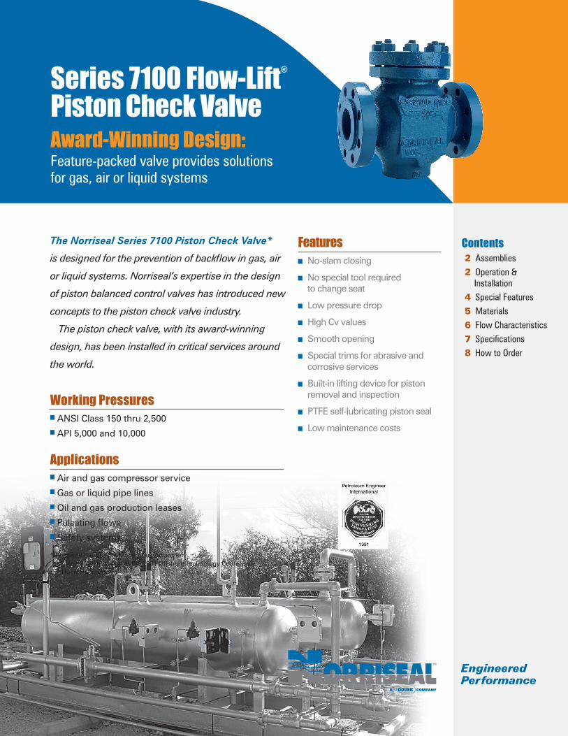
Valve Assembly
Valve Assembly
3
OperationNormal. Flow is directed under the valve piston and lifts it upward. When flow is stopped, the piston descends, closing the valve to prevent flow reversal.
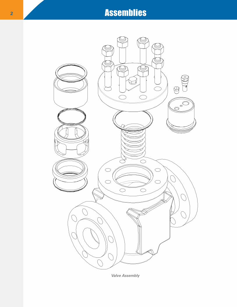
Stabilized/non-slam piston. Pulsating flow through the valve, if unrestricted, would cause the piston to follow the rapidly cycling line pressure, resulting in vibration, chattering and possibly slamming of the piston. The ball check and orifice plug built into the piston are to prevent this from happening. (Fig. 1)
As the piston rises, the pressure in the PTFE sealed cavity above the piston increases, forcing open the ball check. This reduces the cavity pres-sure and allows the piston to rise smoothly. As the pressure and flow decrease, the piston moves downward. The ball check closes, and descent of the piston is restricted by fluid flowing through the orifice plug. This equalizes the pressure in the cav-ity above and below the piston and gives stability to the valve.
InstallationValves 4.00” and smaller may be installed in a vertical position.
Warning: 6.00” and larger valves should NOT be installed in a vertical plane. If a vertical plane is required, please consult factory for special accessories.
ApplicationCompressible fluids. Valves come with ball-check and orifice plug in piston.
Non-compressible fluids. Valves furnished same as for compressible fluids; however, some applications where heavy, viscous liquids are present, the ball check should be removed so piston can stabilize quicker.
Operation & Installation
Figure 1
BALL CHECK
ORIFICE PLUG
4
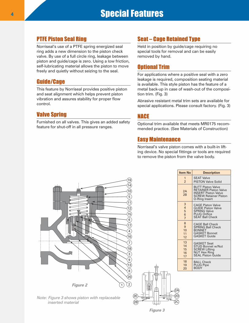
PTFE Piston Seal RingNorriseal’s use of a PTFE spring energized seal ring adds a new dimension to the piston check valve. By use of a full circle ring, leakage between piston and guide/cage is zero. Using a low friction, self-lubricating material allows the piston to move freely and quietly without seizing to the seal.
Guide/CageThis feature by Norriseal provides positive piston and seat alignment which helps prevent piston vibration and assures stability for proper flow control.
Valve SpringFurnished on all valves. This gives an added safety feature for shut-off in all pressure ranges.
Seat – Cage Retained TypeHeld in position by guide/cage requiring no special tools for removal and can be easily removed by hand.
Optional TrimFor applications where a positive seal with a zero leakage is required, composition seating material is available. This style piston has the feature of a metal back-up in case of wash-out of the composi-tion trim. (Fig. 3)
Abrasive resistant metal trim sets are available for special applications. Please consult factory. (Fig. 3)
NACEOptional trim available that meets MR0175 recom-mended practice. (See Materials of Construction)
Easy MaintenanceNorriseal’s valve piston comes with a built-in lift-ing device. No special fittings or tools are required to remove the piston from the valve body.
Special Features
Figure 3
2A
2D
2C2B
2E
1 2
20
8
13
9
3
18
7
16
4
17
6
15
12
11
5
10
14
19
Figure 2
Note: Figure 3 shows piston with replaceableinserted material
Item No Description
12
SEAT ValvePISTON Valve Solid
2A2B
BUTT Piston ValveRETAINER Piston ValveINSERT Piston ValveSCREW Retainer PistonO-Ring Insert
34567
CAGE Piston ValveGUIDE Piston ValveSPRING ValvePLUG OrificeSEAT Ball Check
89101112
CAGE Ball CheckSPRING Ball CheckBONNETGASKET BonnetGASKET Guide
1314151617
GASKET SeatSTUD Bonnet w/NutSCREW LiftingNUT Hex RingSEAL Piston Guide
181920
BALL CheckPLUG PipeBODY
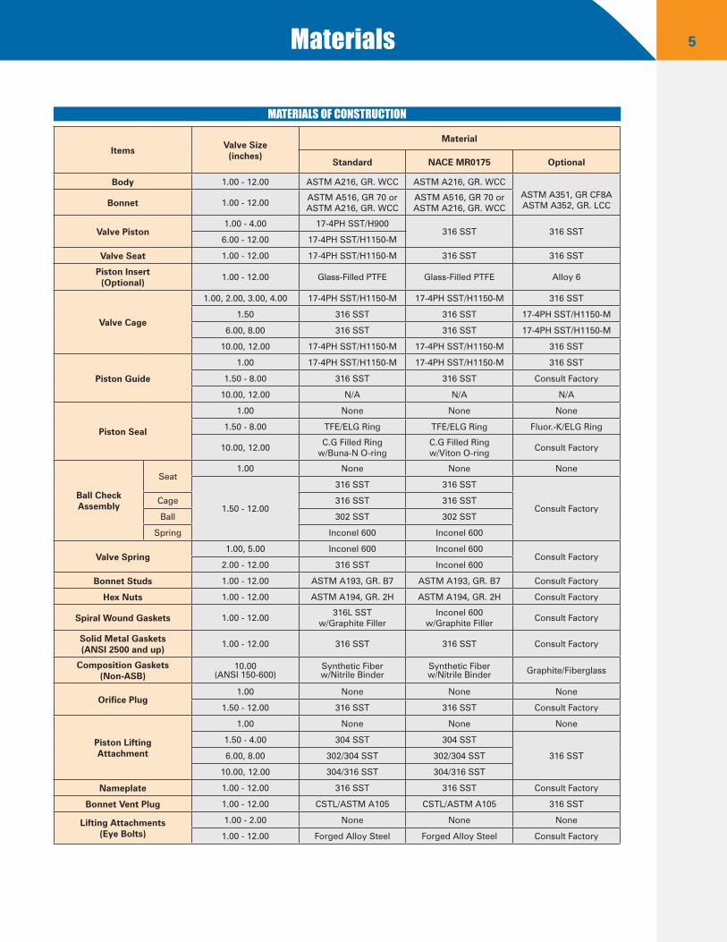
5Materials
Items Valve Size(inches)
Material
Standard NACE MR0175 Optional
Body 1.00 - 12.00 ASTM A216, GR. WCC ASTM A216, GR. WCCASTM A351, GR CF8AASTM A352, GR. LCCBonnet 1.00 - 12.00
ASTM A516, GR 70 or ASTM A216, GR. WCC
ASTM A516, GR 70 orASTM A216, GR. WCC
Valve Piston1.00 - 4.00 17-4PH SST/H900
316 SST 316 SST6.00 - 12.00 17-4PH SST/H1150-M
Valve Seat 1.00 - 12.00 17-4PH SST/H1150-M 316 SST 316 SST
Piston Insert(Optional)
1.00 - 12.00 Glass-Filled PTFE Glass-Filled PTFE Alloy 6
Valve Cage
1.00, 2.00, 3.00, 4.00 17-4PH SST/H1150-M 17-4PH SST/H1150-M 316 SST
1.50 316 SST 316 SST 17-4PH SST/H1150-M
6.00, 8.00 316 SST 316 SST 17-4PH SST/H1150-M
10.00, 12.00 17-4PH SST/H1150-M 17-4PH SST/H1150-M 316 SST
Piston Guide
1.00 17-4PH SST/H1150-M 17-4PH SST/H1150-M 316 SST
1.50 - 8.00 316 SST 316 SST Consult Factory
10.00, 12.00 N/A N/A N/A
Piston Seal
1.00 None None None
1.50 - 8.00 TFE/ELG Ring TFE/ELG Ring Fluor.-K/ELG Ring
10.00, 12.00C.G Filled Ring
w/Buna-N O-ringC.G Filled Ring w/Viton O-ring
Consult Factory
Ball CheckAssembly
Seat1.00 None None None
1.50 - 12.00
316 SST 316 SST
Consult FactoryCage 316 SST 316 SST
Ball 302 SST 302 SST
Spring Inconel 600 Inconel 600
Valve Spring1.00, 5.00 Inconel 600 Inconel 600
Consult Factory2.00 - 12.00 316 SST Inconel 600
Bonnet Studs 1.00 - 12.00 ASTM A193, GR. B7 ASTM A193, GR. B7 Consult Factory
Hex Nuts 1.00 - 12.00 ASTM A194, GR. 2H ASTM A194, GR. 2H Consult Factory
Spiral Wound Gaskets 1.00 - 12.00316L SST
w/Graphite FillerInconel 600
w/Graphite FillerConsult Factory
Solid Metal Gaskets(ANSI 2500 and up)
1.00 - 12.00 316 SST 316 SST Consult Factory
Composition Gaskets(Non-ASB)
10.00(ANSI 150-600)
Synthetic Fiberw/Nitrile Binder
Synthetic Fiberw/Nitrile Binder Graphite/Fiberglass
Orifice Plug1.00 None None None
1.50 - 12.00 316 SST 316 SST Consult Factory
Piston LiftingAttachment
1.00 None None None
1.50 - 4.00 304 SST 304 SST
316 SST6.00, 8.00 302/304 SST 302/304 SST
10.00, 12.00 304/316 SST 304/316 SST
Nameplate 1.00 - 12.00 316 SST 316 SST Consult Factory
Bonnet Vent Plug 1.00 - 12.00 CSTL/ASTM A105 CSTL/ASTM A105 316 SST
Lifting Attachments(Eye Bolts)
1.00 - 2.00 None None None
1.00 - 12.00 Forged Alloy Steel Forged Alloy Steel Consult Factory
MATERIALS OF CONSTRUCTION
6 Flow Characteristics
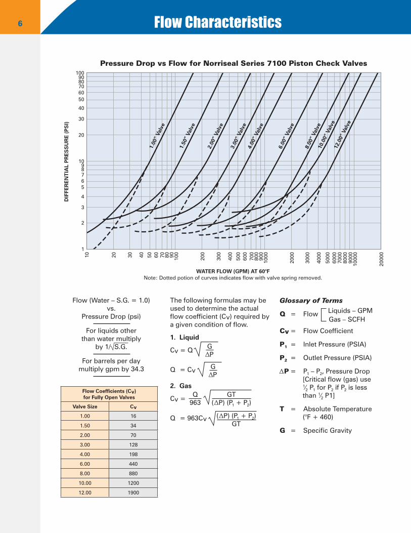
Pressure Drop vs Flow for Norriseal Series 7100 Piston Check ValvesD
IFFE
REN
TIA
L P
RES
SU
RE
(PS
I)
WATER FLOW (GPM) AT 60°FNote: Dotted potion of curves indicates flow with valve spring removed.
1.00
” Va
lve
1.50
” Va
lve
2.00
” Va
lve
3.00
” Va
lve
4.00
” Va
lve
6.00
” Va
lve
8.00
” Va
lve
10.0
0” V
alve
12.0
0” V
alve
10 20 30 40 50 60 70 80 90 100
200
300
400
500
600
700
800
900
1000
2000
3000
4000
5000
6000
7000
8000
9000
1000
0
2000
0
1009080706050
40
30
20
1098765
4
3
2
1
Flow (Water – S.G. = 1.0)vs.
Pressure Drop (psi)
For liquids otherthan water multiply
by 1/ S.G.
For barrels per daymultiply gpm by 34.3
The following formulas may be used to determine the actual flow coefficient (Cv) required by a given condition of flow.
1. Liquid
Cv = Q
Q = Cv
2. Gas
Cv =
Q = 963Cv
Glossary of Terms
Q = Flow Liquids – GPM Gas – SCFH
Cv = Flow Coefficient
P1 = Inlet Pressure (PSIA)
P2 = Outlet Pressure (PSIA)
P = P1 – P2, Pressure Drop[Critical flow (gas) use 1⁄2 P1 for P2 if P2 is less than 1⁄2 P1]
T = Absolute Temperature(°F + 460)
G = Specific Gravity
Flow Coefficients (Cv)for Fully Open Valves
Valve Size Cv
1.00 16
1.50 34
2.00 70
3.00 128
4.00 198
6.00 440
8.00 880
10.00 1200
12.00 1900
G P
G P
GT( P) (P1 + P2)
Q963
( P) (P1 + P2)GT
7Specifications
End Connection Type
BodySize NPT+ Butt-
Weld+Socket-weld+
ANSI Flanged
Flange Type 150 300 600 900 1500 2500
1.00 8.25 8.25 8.25RF 7.25 7.75 8.25 9.38 9.38 N/A
RTJ 7.75 8.25 8.25 9.38 9.38 N/A
1.50 13.00 13.00 13.00RF 8.75 9.25 9.88 12.25 12.25 N/A
RTJ 9.25 9.75 9.88 12.25 12.25 N/A
2.00 11.25 11.25 11.25RF 10.00 10.00 11.25 14.75 14.75 16.88
RTJ 10.50 11.12 11.38 14.88 14.88 17.00
3.00 CF CFRF 11.75 12.50 13.25 15.50 18.12 22.75
RTJ 12.25 13.12 13.38 15.62 18.25 23.00
4.00 CF CFRF 13.38 14.50 15.50 17.00 20.88 26.50
RTJ 14.38 15.12 15.62 17.12 21.00 26.88
6.00 CFRF 17.75 18.62 20.00 24.00 27.75 36.00
RTJ 18.25 19.25 20.12 24.12 28.00 36.50
8.00 CFRF 21.38 22.38 24.00 29.00 32.75 40.25
RTJ 21.88 23.00 24.12 29.12 33.12 40.88
10.00 CFRF 24.50 24.50 31.00 33.00 39.12 C/F
RTJ 25.00 25.12 31.12 33.12 39.38 C/F
12.00 CFRF 29.00 30.50 32.25 40.00 44.50 C/F
RTJ 29.38 31.00 32.38 40.12 45.12 C/F
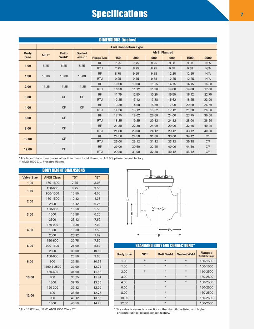
DIMENSIONS (inches)
Valve Size ANSI Class “D” “E”
1.00 150-1500 7.75 3.06
1.50150-600 9.75 3.50
900-1500 10.50 4.00
2.00150-1500 12.12 4.38
2500 15.12 5.25
3.00
150-900 13.50 5.50
1500 16.88 6.25
2500 23.12 7.62
4.00
150-900 18.38 7.00
1500 19.38 7.50
2500 23.12 7.62
6.00
150-600 20.75 7.50
900-1500 25.00 8.62
2500 30.00 10.50
8.00
150-600 26.50 9.00
900 27.88 10.38
1500 & 2500 39.00 12.75
10.00
150-600 34.00 11.63
900 36.25 11.94
1500 39.75 13.00
12.00
150-300 37.12 12.00
600 38.50 12.75
900 40.12 13.50
1500 43.59 14.75
BODY HEIGHT DIMENSIONS
Body Size NPT Butt Weld Socket Weld Flanged(ANSI Ratings)
1.00 * * * 150-1500
1.50 * * * 150-1500
2.00 * * * 150-2500
3.00 * * 150-2500
4.00 * * 150-2500
6.00 * 150-2500
8.00 * 150-2500
10.00 * 150-2500
12.00 * 150-2500
STANDARD BODY END CONNECTIONS**
* For face-to-face dimensions other than those listed above, ie. API 6D, please consult factory+ ANSI 1500 C.L. Pressure Rating
* For 10.00” and 12.0” ANSI 2500 Class C/F **For valve body end connections other than those listed and higher pressure ratings, please consult factory.
D
E
F
4
F/2
8 How to Order
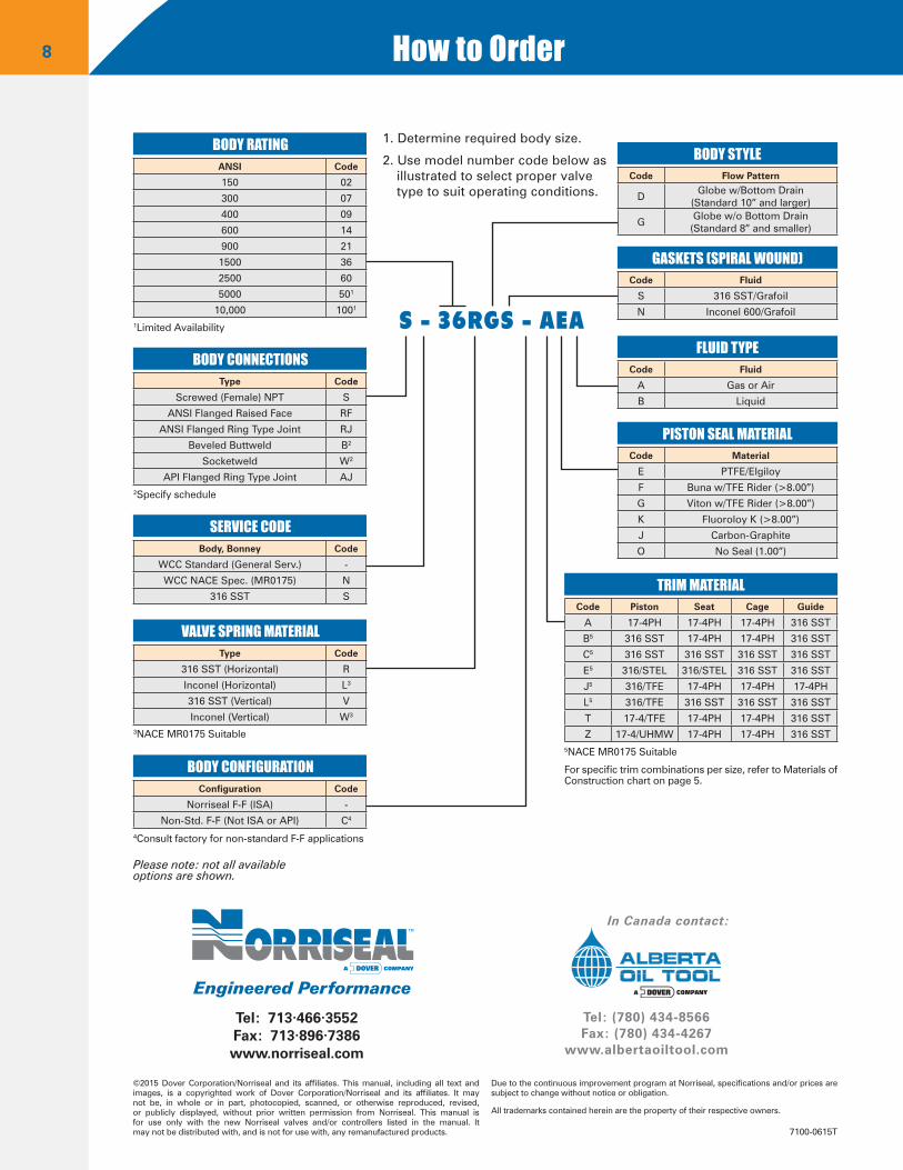
S - 36RGS - AEA
1. Determine required body size.
2. Use model number code below as illustrated to select proper valve type to suit operating conditions.
Please note: not all available options are shown.
1Limited Availability
2Specify schedule
3NACE MR0175 Suitable
4Consult factory for non-standard F-F applications
5NACE MR0175 Suitable
For specific trim combinations per size, refer to Materials of Construction chart on page 5.
BODY RATING
BODY CONNECTIONS
SERVICE CODE
BODY CONFIGURATION
VALVE SPRING MATERIAL
ANSI Code
150 02
300 07
400 09
600 14
900 21
1500 36
2500 60
5000 501
10,000 1001
Type Code
Screwed (Female) NPT S
ANSI Flanged Raised Face RF
ANSI Flanged Ring Type Joint RJ
Beveled Buttweld B2
Socketweld W2
API Flanged Ring Type Joint AJ
Body, Bonney Code
WCC Standard (General Serv.) -
WCC NACE Spec. (MR0175) N
316 SST S
Configuration Code
Norriseal F-F (ISA) -
Non-Std. F-F (Not ISA or API) C4
Type Code
316 SST (Horizontal) R
Inconel (Horizontal) L3
316 SST (Vertical) V
Inconel (Vertical) W3
BODY STYLE
GASKETS (SPIRAL WOUND)
FLUID TYPE
PISTON SEAL MATERIAL
TRIM MATERIAL
Code Flow Pattern
DGlobe w/Bottom Drain
(Standard 10” and larger)
GGlobe w/o Bottom Drain
(Standard 8” and smaller)
Code Fluid
S 316 SST/Grafoil
N Inconel 600/Grafoil
Code Fluid
A Gas or Air
B Liquid
Code Material
E PTFE/Elgiloy
F Buna w/TFE Rider (>8.00”)
G Viton w/TFE Rider (>8.00”)
K Fluoroloy K (>8.00”)
J Carbon-Graphite
O No Seal (1.00”)
Code Piston Seat Cage Guide
A 17-4PH 17-4PH 17-4PH 316 SST
B5 316 SST 17-4PH 17-4PH 316 SST
C5 316 SST 316 SST 316 SST 316 SST
E5 316/STEL 316/STEL 316 SST 316 SST
J5 316/TFE 17-4PH 17-4PH 17-4PH
L5 316/TFE 316 SST 316 SST 316 SST
T 17-4/TFE 17-4PH 17-4PH 316 SST
Z 17-4/UHMW 17-4PH 17-4PH 316 SST
Tel: 713·466·3552Fax: 713·896·7386www.norriseal.com
Tel: (780) 434-8566Fax: (780) 434-4267
www.albertaoiltool.com
Engineered Performance
©2015 Dover Corporation/Norriseal and its affiliates. This manual, including all text and images, is a copyrighted work of Dover Corporation/Norriseal and its affiliates. It may not be, in whole or in part, photocopied, scanned, or otherwise reproduced, revised, or publicly displayed, without prior written permission from Norriseal. This manual is for use only with the new Norriseal valves and/or controllers listed in the manual. It may not be distributed with, and is not for use with, any remanufactured products.
Due to the continuous improvement program at Norriseal, specifications and/or prices are subject to change without notice or obligation.
All trademarks contained herein are the property of their respective owners.
7100-0615T
In Canada contact: