Embed Size (px)
Citation preview

Analog Electronic vs. DDC Controls Comparison ...................................................................................3
Series 7000 Pressure Independent System.............................................................................................5
ComponentsPressure Independent Master Controller..........................................................................................7Heat / Fan Modules ..........................................................................................................................8Setback / Warm-Up Modules ...........................................................................................................9Flow Control Modules.....................................................................................................................10Field Devices
Analog Electronic Thermostat ...................................................................................................11Air Pressure Switch....................................................................................................................12Transformer ...............................................................................................................................12Duct Temperature Sensor ..........................................................................................................13Floating Point Control Direct Coupled Actuator ........................................................................13
Airflow Ranges .....................................................................................................................................13
Series 7000 Calibration Chart ...............................................................................................................14
Control SequencesSingle and Dual Duct Constant Volume and Static Pressure
Control Sequence Table .............................................................................................................15Series Flow Fan Powered (Continuous Fan)
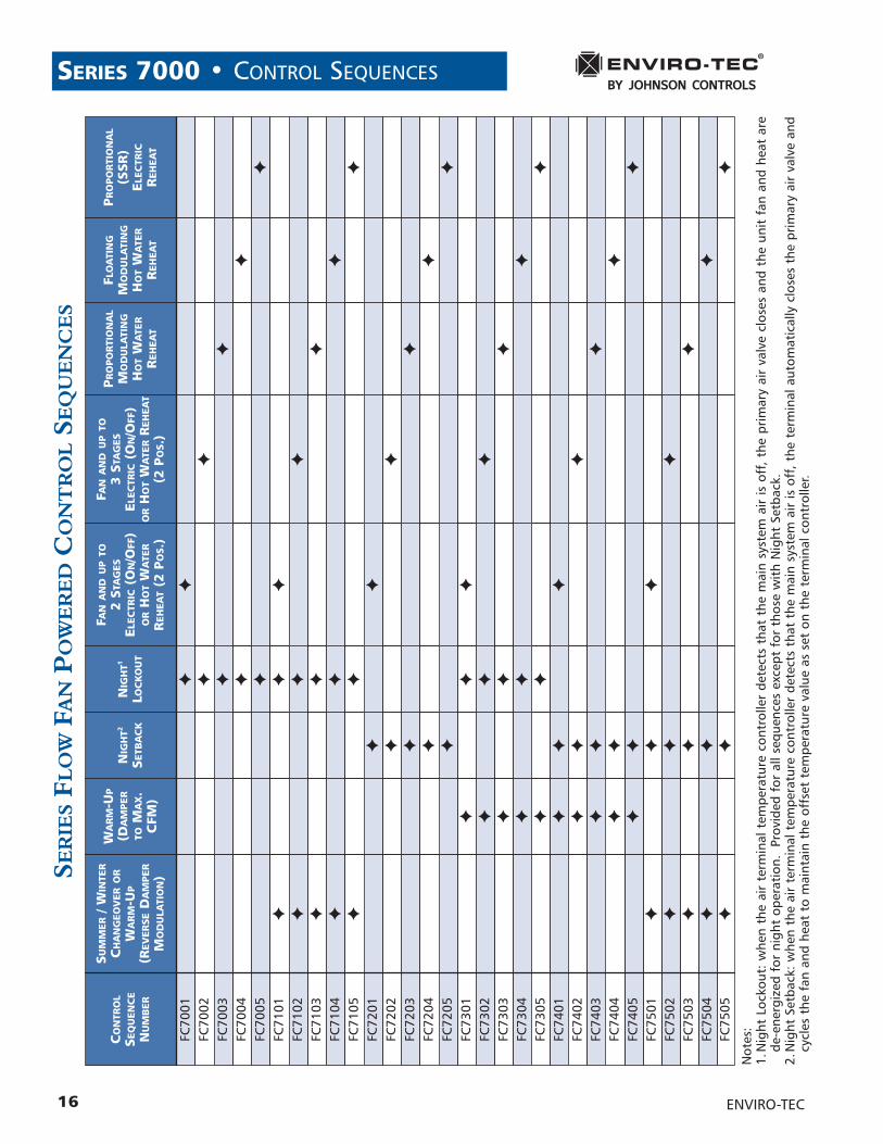
Control Sequence Table .............................................................................................................16Parallel Flow Fan Powered (Intermittent Fan)
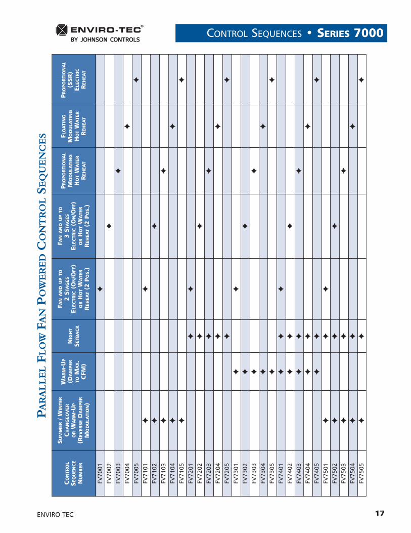
Control Sequence Table .............................................................................................................17
Special Applications............................................................................................................................18
Guide Specifications ...........................................................................................................................19
GENERAL NOTES• All data herein is subject to change without notice. Refer to www.enviro-tec.com for current catalog and
control sequence drawings.• Refer to IOM manual at www.enviro-tec.com.• Refer to Series 7000 Application Guide and sequence drawings at www.enviro-tec.com.• See Analog Electronic Controls drawings at www.enviro-tec.com for connections.
ENVIRO-TEC® • TABLE OF CONTENTS
2 ENVIRO-TEC
ELECTRONIC CONTROLS • SERIES 7000
3
Fierce competition motivates commercial office building ownersand real estate managers to provide comfortable office spacewhile minimizing air conditioningpower consumption and initialconstruction costs. Direct DigitalControls (DDC) are frequentlymounted on each variable air volume (VAV) terminal, permittingcommunication between theautomat ion system centra l monitor and each VAV unit. State-of-the-art Analog Electronic Controls(AEC) for VAV terminals provide aviable lower cost alternative toDDC control.
Both sophisticated, solid state Analog Electronic and DDC VAV controllers provide superior zonecomfort by minimizing room temperature deviation from setpoint. Both systems permit nightsetback and morning warm-upoperation. Both allow the user tofactory and/or field set minimumand maximum airflow settings.Both provide pressure indepen-dent control. Neither requiresannual calibration as do the proportional pneumatic controllers.
In view of the cost difference between Analog E lectronic controllers and DDC controllers(see tables at right), when shouldthe owner and HVAC system designer use DDC VAV control?
DDC control systems provide twoway communications between theVAV terminal controllers and the automation system front end. Abuilding manager, from his office,can view zone temperatures, VAV unit operating status, zone airflow rates, and zone heating andcooling setpoints. He can resetzone temperature setpoints and
ANALOG VARIABLE AIR VOLUME TERMINAL CONTROLSARE A COST EFFECTIVE ALTERNATIVE TO DDC CONTROLS
The VAV controller type significantly impacts the building cost. TheVAV controller contributes between $.21 and $1.44 per square footto the initial cost of a building. The first cost of a DDC VAV con-troller is more than the cost of the VAV single zone terminal. Theanalog VAV control is less than half the cost of the DDC control.
What is the First Cost Premium for DDC Communications Between VAV Terminals and the Building Automation Front End?
Analog Controls DDC Controls
Controller & Thermostat $152 $257
Wiring & Setup $40 $175
Total $192 $432
DDC VS. ANALOG CONTROL COSTS
Analog Controls DDC Controls
Average Zone Area 300 Sq. Ft. 900 Sq. Ft.300 Sq. Ft.900 Sq. Ft.
Cost per Square Foot $.64 $.48$1.44$.21
VAV CONTROLS COST PER SQUARE FOOT
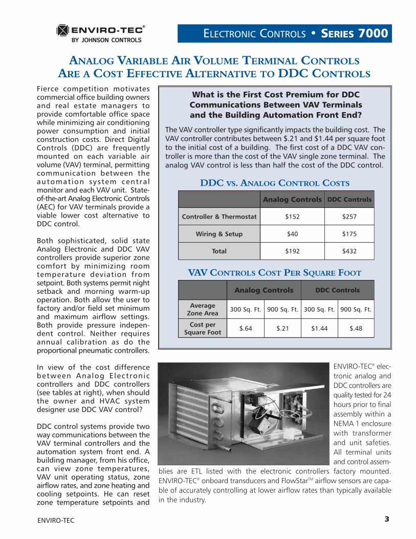
ENVIRO-TEC® elec-tronic analog andDDC controllers arequality tested for 24hours prior to finalassembly within aNEMA 1 enclosurewith transformerand unit safeties.All terminal unitsand control assem-
blies are ETL listed with the electronic controllers factory mounted.ENVIRO-TEC® onboard transducers and FlowStarTM airflow sensors are capa-ble of accurately controlling at lower airflow rates than typically availablein the industry.
ENVIRO-TEC
SERIES 7000 • ELECTRONIC CONTROLS
4
minimum and maximum airflowlimits. Zone controllers can sendan alarm to the central monitorwhen abnormal conditions arise.These are powerful tools whichmeet requirements for some own-ers and tenants.
However, for the typical officespace, the owner may find it morecost effective to limit DDC build-ing automation to large chillers,boilers, major air handling units,fire and life safety systems, andother critical applications.
For non-critical zones, VAV zone terminals may only require AnalogElectronic Controllers with systeminterlock controls. The VAV Analog Electronic Controls have thesame dependability and accuracyas DDC Controls. They also allowthe minimum and maximum CFMsetpoints to be adjusted from thelocal space thermostat for ease ofbalancing the airside of the HVACsystem. In addition, the Series7000 Analog Electronic Controlsincorporate a plug-in modulardesign for ease of adding featuressuch as morning warm-up, nightset back and additional stages of heat, without replacing the original master controller.
Communications wiring for DDCcontrollers may become prohibi-tive when great distances or remotebuildings are involved. In thosecases, stand-alone Analog ElectronicControls may be the only practi-cal choice.
Commissioning DDC VAV systemsrequires factory trained staff famil-iar with DDC hardware andsoftware, increasing the installedcosts of DDC systems. The operatingcost also increases because theowner has to employ highly trainedtechnicians to maintain the systemor pay for expensive yearly
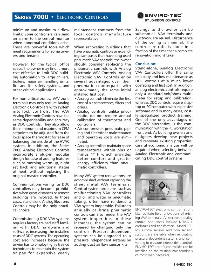
ENVIRO-TEC® electronic control retrofitkits facilitate field renovations of exist-ing VAV terminals. All electronic analogcontrol sequences include NEMA 1enclosures and transformers. Model RFT-MS airflow sensors and flow sensingstations are available when renovatingpressure dependent systems and con-verting to pressure independent control.ENVIRO-TEC® retrofit control kits can beinstalled on the existing VAV terminalsof most manufacturers.
maintenance contracts from thelocal controls manufacture representative.
When renovating buildings thathave pneumatic controls or expand-ing campuses that have long usedpneumatic VAV controls, the ownershould consider replacing thepneumatic controls with AnalogElectronic VAV Controls. AnalogElectronic VAV Controls enjoy several advantages over their pneumatic counterparts withapproximately the same initialinstalled first cost. • Analog controls eliminate the first
cost of air compressors, filters anddriers.
• Analog controls, unlike pneu-matic, do not require annualcalibration of thermostat and controllers.
• Air compressor, pneumatic pip-ing and filter/drier maintenanceand operating costs are elimi-nated.
• Analog controllers maintain spacetemperatures within plus orminus 1° F which provides better comfort and greater energy efficiency than pneu-matic controllers.
Many VAV system renovations areaccomplished without replacing thesheet metal VAV terminals. Control system problems, such asmalfunctioning VAV controllersand oil and water in pneumatic tubing, often have rendered aVAV system inoperable. Failure toannually calibrate pneumatic controls can also render the VAVsystem inoperable. In theseinstances, the system can berepaired by changing only thecontrols. Pressure dependent systems can be upgraded to a pressure independent systems byadding duct airflow sensor kits.
Savings to the owner can be substantial. VAV terminals andductwork are reused. Disturbanceof the ceiling is minimal. The controls retrofit is done in a fraction of the time that a completerenovation might take.
Conclusion:Stand-alone, Analog ElectronicVAV Controllers offer the same reliability and low maintenance asDDC controls at a much lower operating and first cost. In addition,analog electronic controls requireonly a standard volt/ohms multi-meter for setup and calibration,whereas DDC controls require a lap-top or PC computer with expensivesoftware and in many cases, cost-ly specialized product training.One of the only advantages ofthe DDC alternative, is the com-munication with the PC workstationfront end. As building owners anddesigners develop new projectsand renovate existing properties, careful economic analysis will berequired when selecting betweenAnalog Electronic and communi-cating DDC control systems.
ENVIRO-TEC
ELECTRONIC CONTROLS • SERIES 7000
5
The heart of the Series 7000 Con-trol System is the master controller.It incorporates a differential pres-sure transducer, airflow controland air valve modulation circuitry,and a DC power supply. With athermostat and actuator, it servesas a stand-alone cooling only, pres-sure independent VAV controlsystem. The master controller alsoincludes connectors to allow mod-ules to be added in the factory orfield to configure the system for various types of terminals: singleor dual duct, series flow or variablevolume fan. Other standard optionsare discussed below.
FLOW SENSING METHODA center averaging differentialpressure sensor (FlowStarTM) locat-ed in the inlet collar of the VAVterminal is piped to a hot wire differential pressure transducerlocated within the electronic controller. A small orifice in thetransducer creates a minute airflowwhich is proportional to the differential pressure. This flowpasses over a hot thermistor, causing an increase in dissipationand increasing its resistance. Sincecooler air would also have theeffect of increasing resistance, a second thermistor is incorporatedfor temperature compensation.The electronic circuitry causes a constant difference in resistance(temperature) between the twothermistors by increasing power tothe hot thermistor as flow increas-es, and decreasing power to the hotthermistor as flow decreases. Thepower required to maintain this constant difference is the parameterused for flow control.
AIR VALVE CONTROLThe electronic signal developedby the differential pressure trans-ducer is compared to a signaldeveloped from a rapid responsethermistor within the electronic thermostat. Setpoint correspondsto the minimum flow limit set atthe thermostat. The electroniccontroller modulates the air valveactuator from minimum flow tomaximum flow (also set at the thermostat) to provide cooling asnecessary to maintain space temperature. As the actual airflowapproaches airflow setpoint, theactuator control circuitry uses pulsewidth modulation (PWM) to slowthe rate of change of the airflow,thus preventing overshoot andhunting. A calibration curve of DCvoltage vs. CFM is provided sothat flow limits may be set with-out actual airflow being present.
HEAT / FAN CONTROLFour types of heat and two typesof fan control are available with theSeries 7000. Heat options includestaged electric or hot water, floating modulating hot water,proportional modulating hot wateror proportional modulating SSR electric heat. Either terminal and/orbaseboard heat may be controlled.
Both variable volume and series flow fan control strategies are available. For variable volumeapplications, the unit fan is ener-gized one degree below setpoint.A half degree of hysteresis preventsrapid cycling. For series flow appli-cations, the fan runs constantlyduring day mode.
Two methods of reverse fan rota-tion are provided on series flow fanterminals. If system air is failed, theprimary air valve is closed and thefan is de-energized to prevent re-application of air from spinning thefan wheel in reverse before the fanrestarts. On application of powerto the terminal, the primary air valveis closed for three to five minutesbefore the fan is started, in case primary air had spun the fan wheelin reverse before the fan terminalwas powered.
For staged heat applications, astage of electric or hot water heatis energized two degrees below setpoint. Up to two additionalstages may also be energized atthree and four degrees below setpoint. All stages are providedwith a half degree of hysteresis toprevent rapid cycling.
In floating modulating applica-tions, the valve actuator is pulsedin the open direction when thespace temperature reaches twodegrees below setpoint. If the temperature continues to fall, thevalve actuator is pulsed again in theopen direction. If the temperaturedoes not decrease, the valve actuator is not energized, thusremaining in position. On anincrease in space temperature, thevalve actuator is pulsed in theclosed direction. The length of thepulses is proportional to the temperature difference from twodegrees below setpoint.
SERIES 7000 MODULAR, PRESSURE INDEPENDENT VAV CONTROL SYSTEM
ENVIRO-TEC
6
SERIES 7000 • ELECTRONIC CONTROLS
6
An analog signal is used to posit ion a hot water valve actuator in proportional hot waterheat applications. When space temperature drops to two degreesbelow setpoint, the valve is positioned open slightly. If temperature continues to drop,the valve actuator is positioned further open. If temperature rises,the valve actuator is positioned inthe closed direction. The degreeof position change is dependent onthe temperature difference fromtwo degrees below setpoint.
Proportional electric heat applica-tions use an analog signal tocontrol a voltage to a pulse widthmodulation (PWM) circuit which inturn, time proportions the on andoff times of an SSR (solid state relay).When space temperature falls twodegrees below setpoint, very shortpulses of current provide a smallamount of heat. As space tem-perature continues to fall, thepulses become longer to providemore heat.
All types of heat applications forsingle duct VAV terminals featurean auxiliary (heating) minimum.When heat is energized in theseapplications, minimum airflow setpoint is increased to a fieldadjustable volume for optimal airflow with heat.
NIGHT SETBACKAn airflow switch senses whenthe main air handlers have beenshut down, initiating night setback.The controller causes the air valveactuator to close the valve. Whenspace temperature falls to an offset value set on a setback/
warm-up module, the fan is energized and heat is modulatedto maintain temperature. The setpoint temperature in this modeis the day setpoint minus the offset value.
MORNING WARMUP/AUTOMATIC CHANGEOVERAn electronic duct sensor signalsthe presence of warm supply air tothe terminal, which inhibits heat andfan operation and drives the air valveopen to the maximum airflow setpoint. When the thermostat issatisfied, the controller drives theair valve as necessary to maintainsetpoint. For applications such asgas-fired central heat requiringconstant airflow across the heater,a constant volume version of morning warm-up is available. Onsensing warm supply air, the airvalve is driven to maximum airflowsetpoint. This setpoint is maintaineduntil cool primary supply air issensed, when the air valve beginsmodulating in the day (cooling)mode.
PRESSURE CONTROLTwo control sequences provide ameans of controlling static pressurein applications utilizing a constantvolume air handler. The controlleris mounted in a sheet metal enclo-sure which incorporates an integralstatic pressure probe. This assem-bly is mounted on the main ductwith the probe inserted into theduct. As static pressure increases,the electronic controller sends a signal to open a pressure regulat-ing air valve which will bypass airto the return plenum. As static pressure decreases, the air valve isdriven closed, thus bypassing less
air and maintaining constant static pressure in the duct.
WARRANTYThe Series 7000 analog electroniccontrols are warranted for 18months from shipment or 12months from start-up, whichevercomes first.
ENVIRO-TEC
7
CONTROL COMPONENTS • SERIES 7000
7
SPECIFICATIONSSupply Voltage
• 24VAC - 10%, + 15%, 50/60Hz
Power Consumption• 10 VA max. (including actuator)
Flow Sensing Method• Center Averaging FlowStarTM Differential Pressure
Sensor and Hot Wire Differential Pressure Transducer
Range• 0.015" - 1.5" w.g.
Thermostat Outputs• +18 VDC (short circuit protected)
• DC Common
Thermostat Inputs• Flow Setpoint Voltage
Actuator Control Outputs• Pulse Width Modulated• Operates with a 3 wire floating point actuator
Sensor Inputs
• Differential Pressure Transducer (tubing)
Connections• Screw Type, Terminal Block (thermostat)• 1/4" Quick Connect (24VAC input and actuator
outputs)
• 0.025" 50 pin headers (modules)
Ambient Storage Temperature• -35°F to 150°F, 0 to 95% rH, non-condensing
Ambient Operating Temperature• 35°F to 120°F, 10 to 95% rH, non-condensing
Size• 2.25"W x 6.125"L
Enclosure (Bracket) Material Size• 4.375"W x 7.5"L x 2.625"D
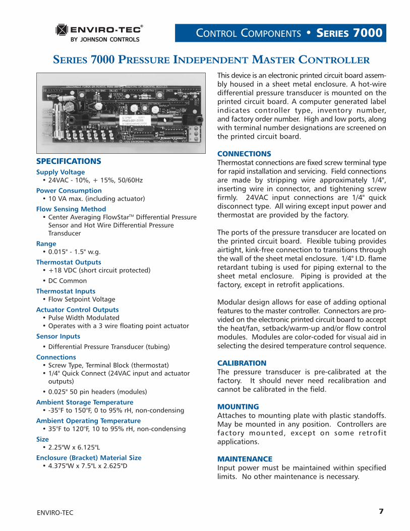
This device is an electronic printed circuit board assem-bly housed in a sheet metal enclosure. A hot-wiredifferential pressure transducer is mounted on theprinted circuit board. A computer generated labelindicates controller type, inventory number, and factory order number. High and low ports, alongwith terminal number designations are screened onthe printed circuit board.
CONNECTIONSThermostat connections are fixed screw terminal typefor rapid installation and servicing. Field connectionsare made by stripping wire approximately 1/4",inserting wire in connector, and tightening screw firmly. 24VAC input connections are 1/4" quick disconnect type. All wiring except input power andthermostat are provided by the factory.
The ports of the pressure transducer are located onthe printed circuit board. Flexible tubing providesairtight, kink-free connection to transitions throughthe wall of the sheet metal enclosure. 1/4" I.D. flameretardant tubing is used for piping external to thesheet metal enclosure. Piping is provided at the factory, except in retrofit applications.
Modular design allows for ease of adding optionalfeatures to the master controller. Connectors are pro-vided on the electronic printed circuit board to acceptthe heat/fan, setback/warm-up and/or flow controlmodules. Modules are color-coded for visual aid inselecting the desired temperature control sequence.
CALIBRATIONThe pressure transducer is pre-calibrated at the factory. It should never need recalibration and cannot be calibrated in the field.
MOUNTINGAttaches to mounting plate with plastic standoffs.May be mounted in any position. Controllers are factory mounted, except on some retrofit applications.
MAINTENANCEInput power must be maintained within specified limits. No other maintenance is necessary.
SERIES 7000 PRESSURE INDEPENDENT MASTER CONTROLLER
ENVIRO-TEC
SERIES 7000 • CONTROL COMPONENTS
8
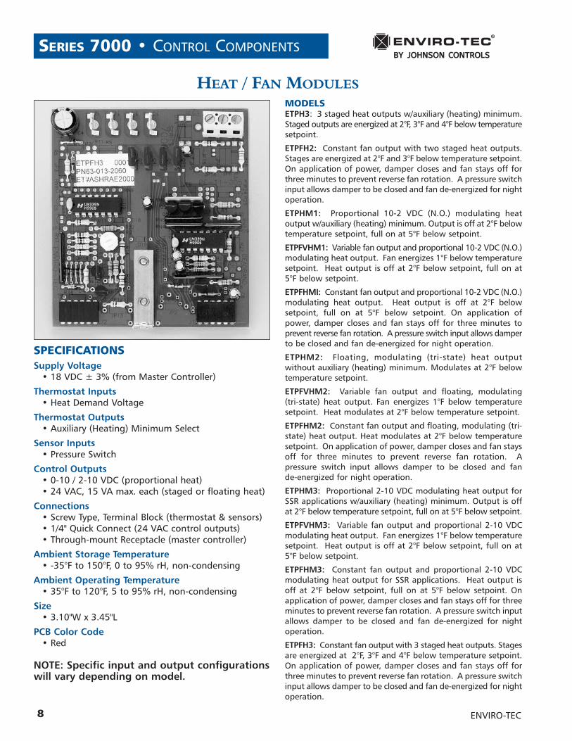
SPECIFICATIONSSupply Voltage
• 18 VDC ± 3% (from Master Controller)
Thermostat Inputs• Heat Demand Voltage
Thermostat Outputs• Auxiliary (Heating) Minimum Select
Sensor Inputs• Pressure Switch
Control Outputs• 0-10 / 2-10 VDC (proportional heat)• 24 VAC, 15 VA max. each (staged or floating heat)
Connections• Screw Type, Terminal Block (thermostat & sensors) • 1/4" Quick Connect (24 VAC control outputs)• Through-mount Receptacle (master controller)
Ambient Storage Temperature• -35°F to 150°F, 0 to 95% rH, non-condensing
Ambient Operating Temperature• 35°F to 120°F, 5 to 95% rH, non-condensing
Size• 3.10"W x 3.45"L
PCB Color Code• Red
NOTE: Specific input and output configurationswill vary depending on model.
HEAT / FAN MODULESMODELSETPH3: 3 staged heat outputs w/auxiliary (heating) minimum.Staged outputs are energized at 2°F, 3°F and 4°F below temperaturesetpoint.
ETPFH2: Constant fan output with two staged heat outputs.Stages are energized at 2°F and 3°F below temperature setpoint.On application of power, damper closes and fan stays off forthree minutes to prevent reverse fan rotation. A pressure switchinput allows damper to be closed and fan de-energized for nightoperation.
ETPHM1: Proportional 10-2 VDC (N.O.) modulating heat output w/auxiliary (heating) minimum. Output is off at 2°F below temperature setpoint, full on at 5°F below setpoint.
ETPFVHM1: Variable fan output and proportional 10-2 VDC (N.O.)modulating heat output. Fan energizes 1°F below temperaturesetpoint. Heat output is off at 2°F below setpoint, full on at5°F below setpoint.
ETPFHMI: Constant fan output and proportional 10-2 VDC (N.O.)modulating heat output. Heat output is off at 2°F below setpoint, full on at 5°F below setpoint. On application ofpower, damper closes and fan stays off for three minutes to prevent reverse fan rotation. A pressure switch input allows damperto be closed and fan de-energized for night operation.
ETPHM2: Floating, modulating (tri-state) heat output without auxiliary (heating) minimum. Modulates at 2°F belowtemperature setpoint.
ETPFVHM2: Variable fan output and floating, modulating (tri-state) heat output. Fan energizes 1°F below temperature setpoint. Heat modulates at 2°F below temperature setpoint.
ETPFHM2: Constant fan output and floating, modulating (tri-state) heat output. Heat modulates at 2°F below temperaturesetpoint. On application of power, damper closes and fan staysoff for three minutes to prevent reverse fan rotation. A pressure switch input allows damper to be closed and fan de-energized for night operation.
ETPHM3: Proportional 2-10 VDC modulating heat output forSSR applications w/auxiliary (heating) minimum. Output is offat 2°F below temperature setpoint, full on at 5°F below setpoint.
ETPFVHM3: Variable fan output and proportional 2-10 VDC modulating heat output. Fan energizes 1°F below temperaturesetpoint. Heat output is off at 2°F below setpoint, full on at5°F below setpoint.
ETPFHM3: Constant fan output and proportional 2-10 VDC modulating heat output for SSR applications. Heat output isoff at 2°F below setpoint, full on at 5°F below setpoint. On application of power, damper closes and fan stays off for threeminutes to prevent reverse fan rotation. A pressure switch inputallows damper to be closed and fan de-energized for night operation.
ETPFH3: Constant fan output with 3 staged heat outputs. Stagesare energized at 2°F, 3°F and 4°F below temperature setpoint.On application of power, damper closes and fan stays off forthree minutes to prevent reverse fan rotation. A pressure switchinput allows damper to be closed and fan de-energized for nightoperation.
ENVIRO-TEC
CONTROL COMPONENTS • SERIES 7000
9
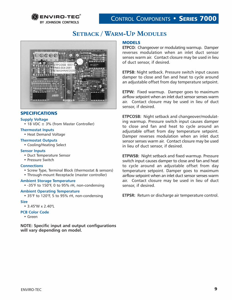
SPECIFICATIONSSupply Voltage
• 18 VDC ± 3% (from Master Controller)
Thermostat Inputs• Heat Demand Voltage
Thermostat Outputs• Cooling/Heating Select
Sensor Inputs• Duct Temperature Sensor• Pressure Switch
Connections• Screw Type, Terminal Block (thermostat & sensors) • Through-mount Receptacle (master controller)
Ambient Storage Temperature• -35°F to 150°F, 0 to 95% rH, non-condensing
Ambient Operating Temperature• 35°F to 120°F, 5 to 95% rH, non-condensing
Size• 3.45"W x 2.40"L
PCB Color Code• Green
NOTE: Specific input and output configurationswill vary depending on model.
SETBACK / WARM-UP MODULES
MODELSETPCO: Changeover or modulating warmup. Damperreverses modulation when an inlet duct sensor senses warm air. Contact closure may be used in lieuof duct sensor, if desired.
ETPSB: Night setback. Pressure switch input causesdamper to close and fan and heat to cycle aroundan adjustable offset from day temperature setpoint.
ETPW: Fixed warmup. Damper goes to maximumairflow setpoint when an inlet duct sensor senses warmair. Contact closure may be used in lieu of duct sensor, if desired.
ETPCOSB: Night setback and changeover/modulat-ing warmup. Pressure switch input causes damperto close and fan and heat to cycle around anadjustable offset from day temperature setpoint.Damper reverses modulation when an inlet duct sensor senses warm air. Contact closure may be usedin lieu of duct sensor, if desired.
ETPWSB: Night setback and fixed warmup. Pressureswitch input causes damper to close and fan and heatto cycle around an adjustable offset from day temperature setpoint. Damper goes to maximum airflow setpoint when an inlet duct sensor senses warmair. Contact closure may be used in lieu of duct sensor, if desired.
ETPSR: Return or discharge air temperature control.
ENVIRO-TEC
SERIES 7000 • CONTROL COMPONENTS
10
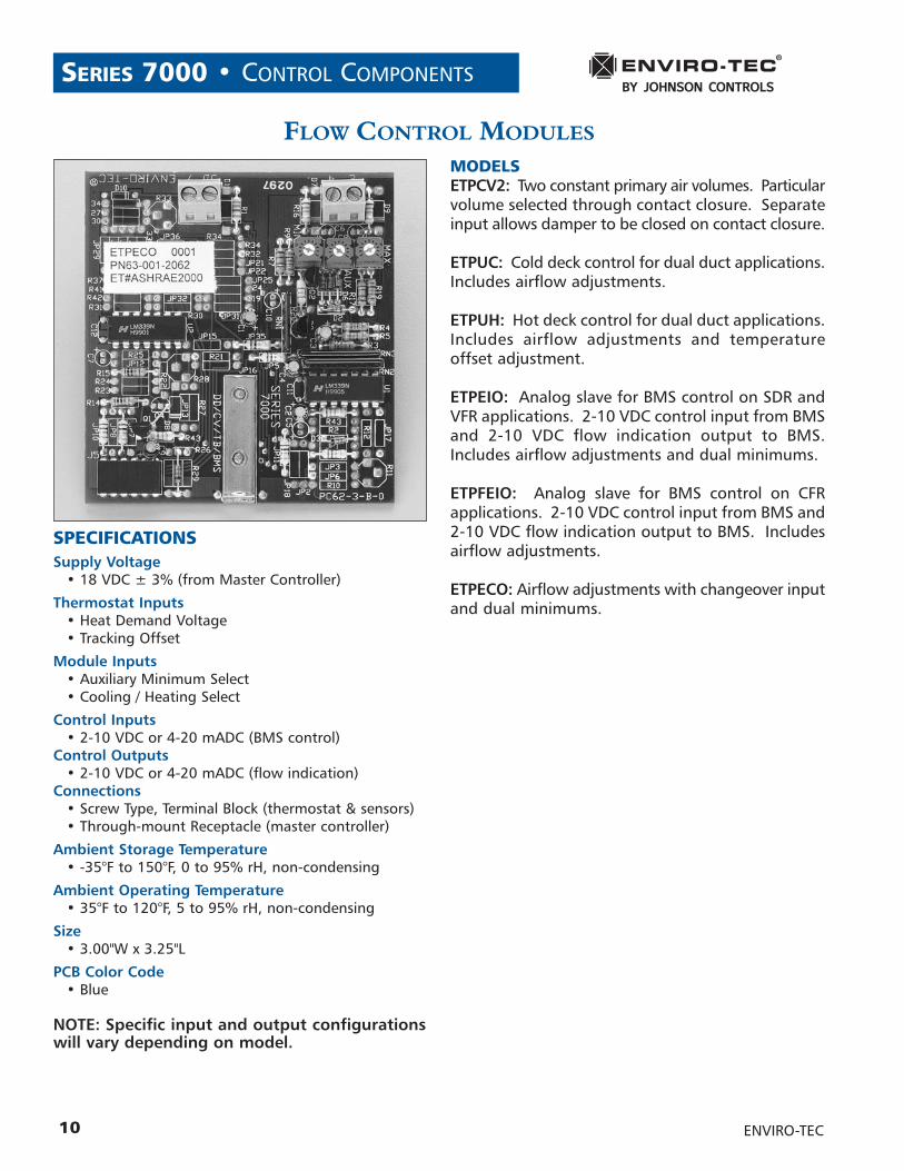
SPECIFICATIONSSupply Voltage
• 18 VDC ± 3% (from Master Controller)
Thermostat Inputs• Heat Demand Voltage• Tracking Offset
Module Inputs• Auxiliary Minimum Select• Cooling / Heating Select
Control Inputs• 2-10 VDC or 4-20 mADC (BMS control)
Control Outputs• 2-10 VDC or 4-20 mADC (flow indication)
Connections• Screw Type, Terminal Block (thermostat & sensors) • Through-mount Receptacle (master controller)
Ambient Storage Temperature• -35°F to 150°F, 0 to 95% rH, non-condensing
Ambient Operating Temperature• 35°F to 120°F, 5 to 95% rH, non-condensing
Size• 3.00"W x 3.25"L
PCB Color Code• Blue
NOTE: Specific input and output configurationswill vary depending on model.
FLOW CONTROL MODULES
MODELSETPCV2: Two constant primary air volumes. Particularvolume selected through contact closure. Separateinput allows damper to be closed on contact closure.
ETPUC: Cold deck control for dual duct applications.Includes airflow adjustments.
ETPUH: Hot deck control for dual duct applications.Includes airflow adjustments and temperature offset adjustment.
ETPEIO: Analog slave for BMS control on SDR andVFR applications. 2-10 VDC control input from BMSand 2-10 VDC flow indication output to BMS.Includes airflow adjustments and dual minimums.
ETPFEIO: Analog slave for BMS control on CFR applications. 2-10 VDC control input from BMS and2-10 VDC flow indication output to BMS. Includesairflow adjustments.
ETPECO: Airflow adjustments with changeover inputand dual minimums.
ENVIRO-TEC
CONTROL COMPONENTS • SERIES 7000
11
ANALOG ELECTRONIC THERMOSTAT
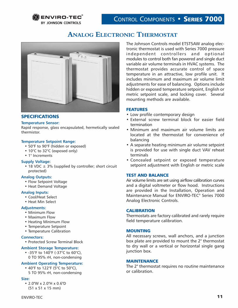
SPECIFICATIONSTemperature Sensor:Rapid response, glass encapsulated, hermetically sealed thermistor.
Temperature Setpoint Range: • 50°F to 90°F (hidden or exposed)• 10°C to 32°C (exposed only)• 1° Increments
Supply Voltage: • 18 VDC ± 3% (supplied by controller; short circuit
protected)
Analog Outputs:• Flow Setpoint Voltage• Heat Demand Voltage
Analog Inputs:• Cool/Heat Select• Heat Min Select
Adjustments:• Minimum Flow• Maximum Flow• Heating Minimum Flow• Temperature Setpoint• Temperature Calibration
Connectors:• Protected Screw Terminal Block
Ambient Storage Temperature:• -35°F to 140°F (-37°C to 60°C),
0 TO 95% rH, non-condensing
Ambient Operating Temperature:• 40°F to 122°F (5°C to 50°C),
5 TO 95% rH, non-condensing
Size:• 2.0"W x 2.0"H x 0.6"D
(51 x 51 x 15 mm)
The Johnson Controls model ETST5AW analog elec-tronic thermostat is used with Series 7000 pressureindependent contro l lers and opt ional modules to control both fan powered and single ductvariable air volume terminals in HVAC systems. Thethermostat provides accurate control of space temperature in an attractive, low profile unit. Itincludes minimum and maximum air volume limitadjustments for ease of balancing. Options includehidden or exposed temperature setpoint, English ormetric setpoint scale, and locking cover. Several mounting methods are available.
FEATURES• Low profile contemporary design• External screw terminal block for easier field
termination• Minimum and maximum air volume limits are
located at the thermostat for convenience of balancing
• A separate heating minimum air volume setpointis provided for use with single duct VAV reheatterminals
• Concealed setpoint or exposed temperature setpoint adjustment with English or metric scale
TEST AND BALANCEAir volume limits are set using airflow calibration curvesand a digital voltmeter or flow hood. Instructionsare provided in the Installation, Operation andMaintenance Manual for ENVIRO-TEC® Series 7000Analog Electronic Controls.
CALIBRATIONThermostats are factory calibrated and rarely requirefield temperature calibration.
MOUNTINGAll necessary screws, wall anchors, and a junctionbox plate are provided to mount the 2" thermostatto dry wall or a vertical or horizontal single gang junction box.
MAINTENANCEThe 2" thermostat requires no routine maintenanceor calibration.
ENVIRO-TEC
SERIES 7000 • CONTROL COMPONENTS
12
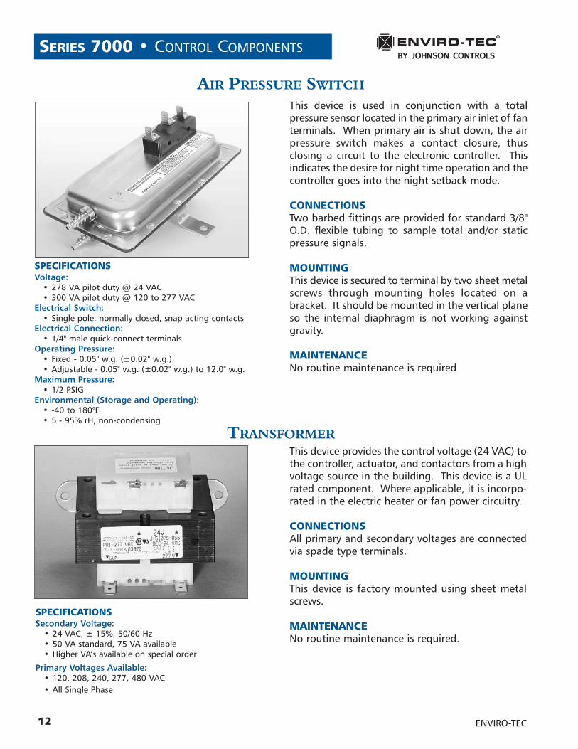
AIR PRESSURE SWITCH
SPECIFICATIONSVoltage:
• 278 VA pilot duty @ 24 VAC• 300 VA pilot duty @ 120 to 277 VAC
Electrical Switch:• Single pole, normally closed, snap acting contacts
Electrical Connection:• 1/4" male quick-connect terminals
Operating Pressure:• Fixed - 0.05" w.g. (±0.02" w.g.)• Adjustable - 0.05" w.g. (±0.02" w.g.) to 12.0" w.g.
Maximum Pressure:• 1/2 PSIG
Environmental (Storage and Operating):• -40 to 180°F• 5 - 95% rH, non-condensing
This device is used in conjunction with a total pressure sensor located in the primary air inlet of fanterminals. When primary air is shut down, the airpressure switch makes a contact closure, thus closing a circuit to the electronic controller. This indicates the desire for night time operation and thecontroller goes into the night setback mode.
CONNECTIONSTwo barbed fittings are provided for standard 3/8"O.D. flexible tubing to sample total and/or static pressure signals.
MOUNTINGThis device is secured to terminal by two sheet metalscrews through mounting holes located on a bracket. It should be mounted in the vertical planeso the internal diaphragm is not working against gravity.
MAINTENANCENo routine maintenance is required
SPECIFICATIONSSecondary Voltage:
• 24 VAC, ± 15%, 50/60 Hz• 50 VA standard, 75 VA available• Higher VA’s available on special order
Primary Voltages Available:• 120, 208, 240, 277, 480 VAC• All Single Phase
This device provides the control voltage (24 VAC) tothe controller, actuator, and contactors from a highvoltage source in the building. This device is a ULrated component. Where applicable, it is incorpo-rated in the electric heater or fan power circuitry.
CONNECTIONSAll primary and secondary voltages are connectedvia spade type terminals.
MOUNTINGThis device is factory mounted using sheet metalscrews.
MAINTENANCENo routine maintenance is required.
TRANSFORMER
ENVIRO-TEC
CONTROL COMPONENTS • SERIES 7000
13ENVIRO-TEC
SPECIFICATIONSResistance:
• 22.1 Kohm, ± 10% at 77°F, NCT
Ambient Storage Temperature:• -35 to 150°F, 0 to 95% rH, non-condensing
Ambient Operating Temperature:• 0 to 120°F, 10 to 95% rH, non-condensing
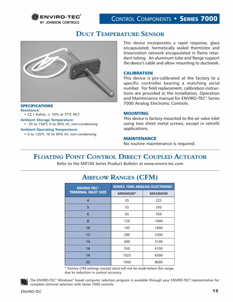
This device incorporates a rapid response, glass encapsulated, hermetically sealed thermistor and linearization network encapsulated in flame retar-dant tubing. An aluminum tube and flange supportthe device‘s cable and allow mounting to ductwork.
CALIBRATIONThis device is pre-calibrated at the factory to a specific controller bearing a matching serial number. For field replacement, calibration instruc-tions are provided in the Installation, Operationand Maintenance manual for ENVIRO-TEC® Series7000 Analog Electronic Controls.
MOUNTINGThis device is factory mounted to the air valve inletusing two sheet metal screws, except in retrofitapplications.
MAINTENANCENo routine maintenance is required.
ENVIRO-TEC®
TERMINAL INLET SIZE
SERIES 7000 ANALOG ELECTRONIC
MINIMUM* MAXIMUM
4 35 225
5 55 350
6 65 550
8 120 1000
10 195 1600
12 280 2300
14 400 3100
16 550 4100
19 1025 6500
22 1450 8000
The ENVIRO-TEC® Windows® based computer selection program is available through your ENVIRO-TEC® representative forcomplete terminal selection with Series 7000 controls.
* Factory CFM settings (except zero) will not be made below this range,due to reduction in control accuracy.
DUCT TEMPERATURE SENSOR
AIRFLOW RANGES (CFM)
FLOATING POINT CONTROL DIRECT COUPLED ACTUATORRefer to the M9104 Series Product Bulletin at www.enviro-tec.com
SERIES 7000 • CONTROL COMPONENTS
14
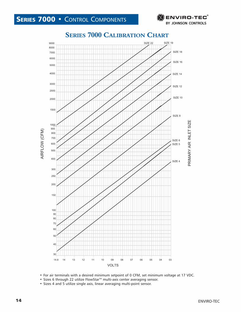
SERIES 7000 CALIBRATION CHART
• For air terminals with a desired minimum setpoint of 0 CFM, set minimum voltage at 17 VDC.• Sizes 6 through 22 utilize FlowStarTM multi-axis center averaging sensor. • Sizes 4 and 5 utilize single axis, linear averaging multi-point sensor.
ENVIRO-TEC
CONTROL SEQUENCES • SERIES 7000
15ENVIRO-TEC
SIN
GL
EA
ND
DU
AL
DU
CT
CO
NT
RO
LSE
QU
EN
CE
S
CO
NTR
OL
S EQ
UEN
CE
NU
MB
ER
S UM
MER
/W
INTE
RC
HA
NG
EOV
ERO
RW
AR
M-U
P(R
EVER
SED
AM
PER
MO
DU
LATI
ON)
WA
RM
-UP
(DA
MP
ERTO
MA
X.
CFM
)
DU
AL
MIN
IMU
MC
FMS E
TPO
INTS
CO
NST
AN
TV
OLU
ME2
S TA
TIC
PR
ESSU
RE
CO
NTR
OL
(0.1
-
1.0
" W
.C.)
S TA
TIC
PR
ESSU
RE
CO
NTR
OL
(0.5
-
2.5
" W
.C.)
NO
HEA
TO
PTI
ON
S(C
OO
LIN
GO
NLY
)
UP
TO3
S TA
GES
E LEC
TRIC
(ON/O
FF)
OR
HO
TW
ATE
RR
EHEA
T1
(2 P
OS.
)
PR
OP
OR
TIO
NA
LM
OD
ULA
TIN
GH
OT
WA
TER
REH
EAT1
F LO
ATI
NG
MO
DU
LATI
NG
HO
TW
ATE
RR
EHEA
T1
PR
OP
OR-
TIO
NA
L(S
SR)
E LEC
TRIC
REH
EAT1
SD70
00�
SD70
01�
�SD
7003
��
SD70
04�
�SD
7005
��
SD71
00�
SD71
01�
��
SD71
03�
��
SD71
04�
��
SD71
05�
��
SD73
00�
�SD
7301
��
�SD
7303
��
�SD
7304
��
�SD
7305
��
�SD
7600
�2
SD76
06�
SD76
07�
CO
NST
AN
TO
RV
AR
IALB
EV
OLU
ME
DIS
CH
AR
GE
CO
NTR
OL
VA
RIA
BLE
VO
LUM
EW
ITH
Z ER
OH
EATI
NG
MIN
IMU
M3
DT7
100
�D
D72
00�
SIN
GLE
DU
CT
DU
AL
DU
CT
Not
es:
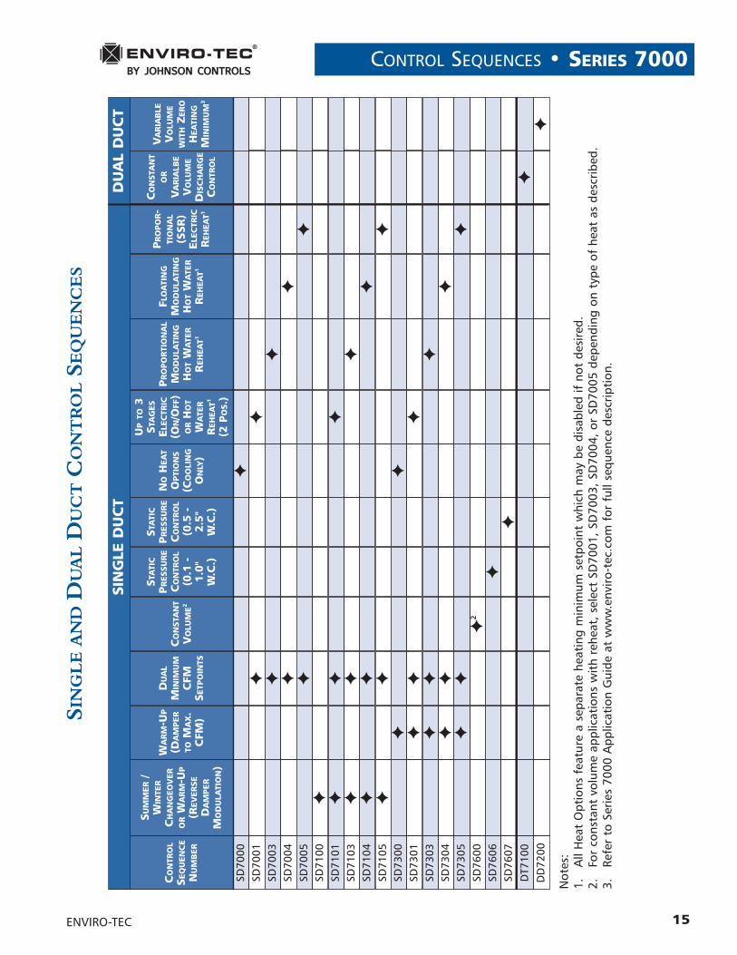
1.A
ll H
eat
Opt
ions
fea
ture
a s
epar
ate
heat
ing
min
imum
set
poin
t w
hich
may
be
disa
bled
if n
ot d
esir
ed.
2.Fo
r co
nsta
nt v
olum
e ap
plic
atio
ns w
ith
rehe
at, s
elec
t SD
7001
, SD
7003
, SD
7004
, or
SD70
05 d
epen
ding
on
type
of
heat
as
desc
ribe
d.3.
Refe
r to
Ser
ies
7000
App
licat
ion
Gui
de a
t w
ww
.env
iro-
tec.
com
for
ful
l seq
uenc
e de
scri
ptio
n.
SERIES 7000 • CONTROL SEQUENCES
16
SER
IES
FLO
WFA
NP
OW
ER
ED
CO
NT
RO
LSE
QU
EN
CE
S
CO
NTR
OL
SEQ
UEN
CE
NU
MB
ER
SUM
MER
/ W
INTE
RC
HA
NG
EOV
ERO
RW
AR
M-U
P(R
EVER
SED
AM
PER
MO
DU
LATI
ON)
WA
RM
-UP
(DA
MP
ERTO
MA
X.
CFM
)
NIG
HT2
SETB
AC
KN
IGH
T1
LOC
KO
UT
FAN
AN
DU
PTO
2 S
TAG
ESEL
ECTR
IC(O
N/O
FF)
OR
HO
TW
ATE
RR
EHEA
T(2
PO
S.)
FAN
AN
DU
PTO
3 S
TAG
ESEL
ECTR
IC(O
N/O
FF)
OR
HO
TW
ATE
RR
EHEA
T(2
PO
S.)
PR
OP
OR
TIO
NA
LM
OD
ULA
TIN
GH
OT
WA
TER
REH
EAT
F LO
ATI
NG
MO
DU
LATI
NG
HO
TW
ATE
RR
EHEA
T
PR
OP
OR
TIO
NA
L(S
SR)
E LEC
TRIC
REH
EAT
FC70
01�
�
FC70
02�
�
FC70
03�
�
FC70
04�
�
FC70
05�
�
FC71
01�
��
FC71
02�
��
FC71
03�
��
FC71
04�
��
FC71
05�
��
FC72
01�
�
FC72
02�
�
FC72
03�
�
FC72
04�
�
FC72
05�
�
FC73
01�
��
FC73
02�
��
FC75
05FC
7504
FC75
03FC
7502
FC75
01FC
7405
FC74
04FC
7403
FC74
02FC
7401
FC73
05FC
7304
FC73
03
�����
��������
����������
���
��
��
���
���
���
Not
es:
1.N
ight
Loc
kout
: w
hen
the
air
term
inal
tem
pera
ture
con
trol
ler
dete
cts
that
the
mai
n sy
stem
air
is o
ff,
the
prim
ary
air
valv
e cl
oses
and
the
uni
t fa
n an
d he
at a
rede
-ene
rgiz
ed f
or n
ight
ope
rati
on.
Prov
ided
for
all
sequ
ence
s ex
cept
for
tho
se w
ith
Nig
ht S
etba
ck.
2.N
ight
Set
back
: w
hen
the
air
term
inal
tem
pera
ture
con
trol
ler
dete
cts
that
the
mai
n sy
stem
air
is o
ff,
the
term
inal
aut
omat
ical
ly c
lose
s th
e pr
imar
y ai
r va
lve
and
cycl
es t
he f
an a
nd h
eat
to m
aint
ain
the
offs
et t
empe
ratu
re v
alue
as
set
on t
he t
erm
inal
con
trol
ler.
ENVIRO-TEC
CONTROL SEQUENCES • SERIES 7000
17ENVIRO-TEC
PA
RA
LL
EL
FLO
WFA
NP
OW
ER
ED
CO
NT
RO
LSE
QU
EN
CE
S
CO
NTR
OL
SEQ
UEN
CE
NU
MB
ER
SUM
MER
/ W
INTE
RC
HA
NG
EOV
ERO
RW
AR
M-U
P(R
EVER
SED
AM
PER
MO
DU
LATI
ON)
WA
RM
-UP
(DA
MP
ERTO
MA
X.
CFM
)
NIG
HT
S ETB
AC
K
FAN
AN
DU
PTO
2 S
TAG
ESEL
ECTR
IC(O
N/O
FF)
OR
HO
TW
ATE
RR
EHEA
T(2
PO
S.)
FAN
AN
DU
PTO
3 S
TAG
ESEL
ECTR
IC(O
N/O
FF)
OR
HO
TW
ATE
RR
EHEA
T(2
PO
S.)
PR
OP
OR
TIO
NA
LM
OD
ULA
TIN
GH
OT
WA
TER
REH
EAT
FLO
ATI
NG
MO
DU
LATI
NG
HO
TW
ATE
RR
EHEA
T
PR
OP
OR
TIO
NA
L(S
SR)
E LEC
TRIC
REH
EAT
FV70
01�
FV70
02�
FV70
03�
FV70
04�
FV70
05�
FV71
01�
�
FV71
02�
�
FV71
03�
�
FV71
04�
�
FV71
05�
�
FV72
01�
�
FV72
02�
�
FV72
03�
�
FV72
04�
�
FV72
05�
�
FV73
01�
�
FV73
02�
�
FV75
05FV
7504
FV75
03FV
7502
FV75
01FV
7405
FV74
04FV
7403
FV74
02FV
7401
FV73
05FV
7304
FV73
03
�����
��������
����������
��
��
���
���
���
GENERAL NOTESSince the actions below involve control signals, theymust be done with a dry contact closure (contact clo-sure cannot be paralleled from terminal to terminal):
CLOSE DAMPERTo close the air valve, open ETPM7 terminal 6 to ther-mostat terminal 5.
Sample Application: Could be used during smokesequences to isolate different areas.
OPEN DAMPERTo open the air valve fully, short ETPM7 terminal 6to ETPM7 terminal 7.
Sample Application: Could be used by airside testand balance to set CFM of the air handler.
OPEN AIR VALVE TO MAXIMUM CFM SETPOINTTo open the air valve to maximum CFM setpoint, dis-able heat and disable VFR fan (if applicable), shortETPH terminal 5 to ETPH terminal 7 (if present) or ETPM7terminal 7.
Sample Application: Could be used during airsidetest and balance.
DISABLE HEATTo disable heat and heating minimum (SD only), shortETPM7 terminal 4 to ETPM7 terminal 7.
Sample Application: Could be used if boiler is offand you don‘t want the VAV terminals to go into heat-ing mode.
CONNECTING MORE THAN ONE BOX TO A THERMOSTATTo operate up to four air terminals from one ther-mostat, wire first terminal to thermostat per sequencediagram. Parallel connector terminals 5 (if present),6 and 7 to other air terminals. Do not connect con-nector terminal 8‘s together as serious damage willresult. Since balancing is performed at the thermo-stat, all air terminals should be balanced with samevoltages. In addition, for best results, all air termi-nals connected for this application should be the samesize.
Sample Application: Could be used in open area whereone thermostat could sense general temperature andcontrol several air terminals in unison.
SERIES 7000 • SPECIAL APPLICATIONS
18 ENVIRO-TEC
SPECIAL APPLICATIONS • SERIES 7000
19
GUIDE SPECIFICATIONS • SERIES 7000
ENVIRO-TEC
GENERALFurnish and install an ENVIRO-TEC®
Series 7000 Pressure Independent Ana-log Electronic Control System whereindicated on the plans and in the spec-ifications. The complete system shall befully operational and include the fol-lowing:• Single duct, dual duct, and/or fan
powered terminal units• Pressure independent Series 7000 ana-
log electronic zone controllers withintegral differential pressure trans-ducer
• Analog electronic wall thermostat• Electronic air valve actuator• 24 VAC control transformers• Air pressure switches as required• Electronic duct temperature sensors as
required
TERMINAL UNITSProvide terminal units with multi-axis cen-ter averaging differential pressure sensoras specified in Section___, “Air TerminalUnits.”
ANALOG ELECTRONIC ZONE CONTROLLERThe fully standalone controller shallconsist of an electronic circuit board withintegral flow-compensated differentialpressure transducer. The circuit boardshall incorporate different type terminalsfor AC and DC connection to preventdamage caused by inadvertent fieldwiring errors. Thermostat, sensor andcontact closure terminations shall bethrough screw terminal connectors foreasy field termination. 24 VAC termi-nations shall be of the quick-connect type.The circuit board shall also incorporatean automotive-style, glass tube fusecircuit protector for ease of local replace-ment.
Modular design shall allow for ease ofadding optional features such as fan,stages of heat, morning warm-up, sum-mer/winter changeover, night setback andsmoke purge and shall be accomplishedby selecting the appropriate modular cardand plugging it into the existing mas-ter controller. Controllers that requirereplacement to change or update optionsare not acceptable. The use of sepa-rately wired modules to implementoptional features is not acceptable dueto the increased risk of control problemsfrom inadvertent field wiring errors andintermittent connections.
Series flow fan terminal controllers shallincorporate logic to prevent reverserotation of the unit fan on power inter-ruption or introduction of primary air.
REHEAT CONTROLThe plug-in Heat Modules, used with sin-gle duct or fan powered air terminalcontrollers, shall be capable of control-ling the following types of ductedreheat: 1) Control up to three stages ofElectric Duct Heat, 2) Provide 3-wire float-ing point control for Hot Water Reheat,3) Provide proportional modulating con-trol for Hot Water Reheat, 4) Provideproportional SSR control for ElectricDuct Heat.
ELECTRONIC DUCT TEMPERATURESENSORWhere required by the control sequence,each control package shall include a sup-ply air duct temperature sensor furnished,mounted and wired by the terminalunit manufacturer.
Summer/Winter Changeover: Whenthe supply air temperature increases toa field adjustable setpoint, between 50°and 90°F, the controller shall automati-cally reverse the control action of the airvalve and modulate the air valve to con-dition the space with warm air from theRTU or Air Handler.
Morning Warmup: When the supply airtemperature increases to a field adjustablesetpoint, between 50° and 90°F, thecontroller shall automatically drive the airvalve to the Maximum CFM position andallow for conditioning of the space withwarm air from the RTU or Air Handler.
DIFFERENTIAL PRESSURE TRANSDUCERThe flow-compensated differential pres-sure transducer shall be permanentlymounted on the analog electronic con-trol circuit board. The analog electroniccontrol shall drive the transducer insuch a way as to produce a voltage out-put proportional to flow. Transducerswith outputs proportional to differen-tial pressure are not acceptable. Thecontroller shall use the flow proportionalvoltage output to maintain desired air-flow within five percent of setpointregardless of changes in system staticpressure. Inlet mounted, single point hot-wire velocity transducers are notacceptable.
ANALOG ELECTRONIC WALL THERMOSTATThe analog electronic thermostat circuitboard shall incorporate a glass encap-sulated, hermetically sealed rapid responsethermistor, a hidden temperature setpointwith scale marked in one degree Fahren-heit increments, and maximum, coolingminimum and heating minimum airflow
limit adjustments. All thermostat sig-nals shall be low voltage, low current forshort circuit protected DC.
The thermostat shall be capable ofbeing installed directly to drywall, or toa horizontally or vertically mounted sin-gle-gang junction box with an adapterplate provided. The thermostat shall notprotrude further than 5/8" from thewall or adapter plate when installed.
Where required by the control sequence,each thermostat shall include both heat-ing and cooling minimum airflowadjustments. The control system shallallow both the heat and heating mini-mum to be disabled via a dry contactclosure provided by the Temperature Con-trols Contractor.
ELECTRONIC ACTUATORThe electronic actuator shall be a separate component from the control sys-tem. Due to the high cost of replacementparts after the warranty period, systemswith the actuator integral to the elec-tronic controller are not acceptable.
The electronic actuator shall be capableof stalling indefinitely at the terminal unit‘smechanical stops without damage eitherto the actuator or the terminal, and main-tain positive mechanical pressure againstthe unit‘s closed foam seal to preventexcessive airflow leakage. The use of endswitches to limit the damper‘s mechan-ical travel is not acceptable. DC currentto the actuator motor in the stall posi-tion shall be electronically limited toprevent damage to the motor due toexcessive power dissipation.
CONTROL TRANSFORMERProvide a 24 VAC control transformersized to match the power requirementsof the terminal and voltage available inthe building.
AIR PRESSURE SWITCHWhere required by the control sequence,each control package shall include an airpressure switch furnished, mountedand wired by the terminal unit manu-facturer. When the switch senses thatthe system static pressure has failed, thecontroller and unit shall automaticallyswitch to the night setback mode. Fanand heat shall be used to maintain theseparate night temperature offset.

Printed on recycled paper
Catalog: ET130.13-TD1 (1108) Supersedes: Nothing© 2008 Johnson Controls, Inc. P.O. Box 423, Milwaukee, WI 53201 Printed in USAwww.johnsoncontrols.com