Embed Size (px)
Citation preview
96
Series 61 16 mm 22.5 mm 21 x 21 mm 21 x 27 mm IP65 5 A 250 VAC
Choose one component from each of the coloured sections to assemble a complete switch. For other options or further information please contact your local sales office.
INDICATOR pushbuTTON e-sTOp keylOCk seleCTOR
Product Profile
The Series 61 is a high quality, modular switch range that includes pushbuttons, indicators, selector switches, keylock switches and Emergency-stops. Available in raised or flush mount.
Self cleaning snap-action and slow-make switching elements available.
Technical data see page 103
IP65 Protection •Switch Rating, 5 A, 250 VAC•Raised Mounting into 16 mm cut out•Flush Mounting into 22.5 mm, 21 x 21 mm and 21 x 27 mm cut out•Illumination using midget-grooved T13/4 lamps or single chip LED’s• All standard lenses are transparent with translucent diffuser available in •different coloursFor keylock switches 135 different keys are available•
Accessories
LED
Accessories
Accessories
Accessories
LED
Accessories
Accessories
Accessories
Accessories
Accessories
LED
Switching element
Switching element
Switching element
Switching element
Switching element
Indicator
Illuminated pushbutton
Keylock switch
Selector switch
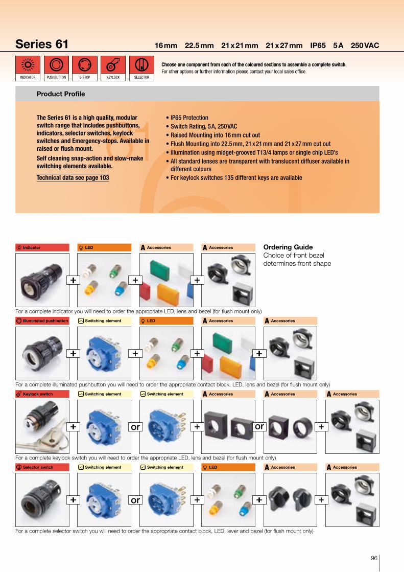
Ordering GuideChoice of front bezel determines front shape
For a complete indicator you will need to order the appropriate LED, lens and bezel (for flush mount only)
For a complete illuminated pushbutton you will need to order the appropriate contact block, LED, lens and bezel (for flush mount only)
For a complete keylock switch you will need to order the appropriate LED, lens and bezel (for flush mount only)
For a complete selector switch you will need to order the appropriate contact block, LED, lever and bezel (for flush mount only)
or
or
or
97
1 2 3 4 1 2 3 4
Series 6116 mm 22.5 mm 21 x 21 mm 21 x 27 mm IP65 5 A 250 VAC
eleMeNT leD ACCessORIes
Choose one component from each of the coloured sections to assemble a complete switch. For other options or further information please contact your local sales office.
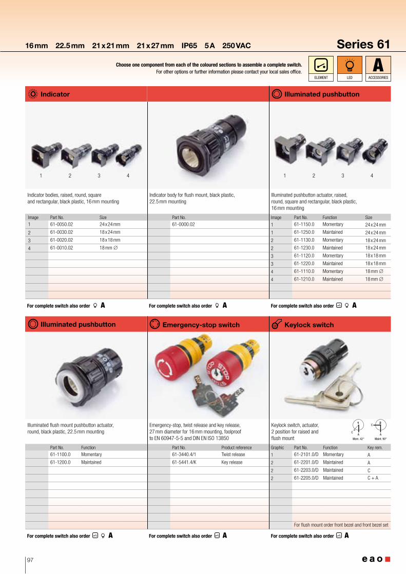
Indicator
Indicator bodies, raised, round, square and rectangular, black plastic, 16 mm mounting
Image Part No. Size
1 61-0050.02 24 x 24 mm
2 61-0030.02 18 x 24 mm
3 61-0020.02 18 x 18 mm
4 61-0010.02 18 mm ∅
For complete switch also order
Illuminated pushbutton
Illuminated pushbutton actuator, raised, round, square and rectangular, black plastic, 16 mm mounting
Image Part No. Function Size
1 61-1150.0 Momentary 24 x 24 mm
1 61-1250.0 Maintained 24 x 24 mm
2 61-1130.0 Momentary 18 x 24 mm
2 61-1230.0 Maintained 18 x 24 mm
3 61-1120.0 Momentary 18 x 18 mm
3 61-1220.0 Maintained 18 x 18 mm
4 61-1110.0 Momentary 18 mm ∅
4 61-1210.0 Maintained 18 mm ∅
For complete switch also order
Illuminated pushbutton
Illuminated flush mount pushbutton actuator, round, black plastic, 22.5 mm mounting
Part No. Function
61-1100.0 Momentary
61-1200.0 Maintained
For complete switch also order
Indicator body for flush mount, black plastic, 22.5 mm mounting
Part No.
61-0000.02
For complete switch also order
Emergency-stop switch
Emergency-stop, twist release and key release, 27 mm diameter for 16 mm mounting, foolproof to EN 60947-5-5 and DIN EN ISO 13850
Part No. Product reference
61-3440.4/1 Twist release
61-5441.4/K Key release
For complete switch also order
Keylock switch
Keylock switch, actuator, 2 position for raised and flush mount
Graphic Part No. Function Key rem.
1 61-2101.0/D Momentary A
2 61-2201.0/D Maintained A
2 61-2203.0/D Maintained C
2 61-2205.0/D Maintained C + A
For flush mount order front bezel and front bezel set
For complete switch also order
C
CA A
Mom. 42° Maint. 90°
1 2
98
1 2
Series 61 16 mm 22.5 mm 21 x 21 mm 21 x 27 mm IP65 5 A 250 VAC
Choose one component from each of the coloured sections to assemble a complete switch. For other options or further information please contact your local sales office.
INDICATOR pushbuTTON e-sTOp keylOCk seleCTOR
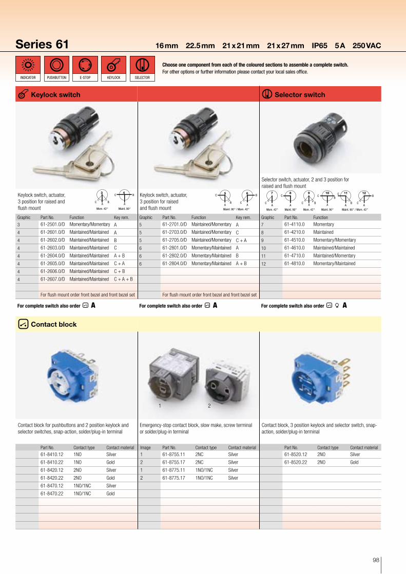
Contact block
Contact block for pushbuttons and 2 position keylock and selector switches, snap-action, solder/plug-in terminal
Part No. Contact type Contact material
61-8410.12 1NO Silver
61-8410.22 1NO Gold
61-8420.12 2NO Silver
61-8420.22 2NO Gold
61-8470.12 1NO/1NC Silver
61-8470.22 1NO/1NC Gold
Emergency-stop contact block, slow make, screw terminal or solder/plug-in terminal
Image Part No. Contact type Contact material
1 61-8755.11 2NC Silver
2 61-8755.17 2NC Silver
1 61-8775.11 1NO/1NC Silver
2 61-8775.17 1NO/1NC Silver
Contact block, 3 position keylock and selector switch, snap-action, solder/plug-in terminal
Part No. Contact type Contact material
61-8520.12 2NO Silver
61-8520.22 2NO Gold
Keylock switch, actuator, 3 position for raised and flush mount
Graphic Part No. Function Key rem.
3 61-2501.0/D Momentary/Momentary A
4 61-2601.0/D Maintained/Maintained A
4 61-2602.0/D Maintained/Maintained B
4 61-2603.0/D Maintained/Maintained C
4 61-2604.0/D Maintained/Maintained A + B
4 61-2605.0/D Maintained/Maintained C + A
4 61-2606.0/D Maintained/Maintained C + B
4 61-2607.0/D Maintained/Maintained C + A + B
For flush mount order front bezel and front bezel set
For complete switch also order
Keylock switch
C B
C BAA
Mom. 42° Maint. 90°
3 4 Keylock switch, actuator, 3 position for raised and flush mount
Graphic Part No. Function Key rem.
5 61-2701.0/D Maintained/Momentary A
5 61-2703.0/D Maintained/Momentary C
5 61-2705.0/D Maintained/Momentary C + A
6 61-2801.0/D Momentary/Maintained A
6 61-2802.0/D Momentary/Maintained B
6 61-2804.0/D Momentary/Maintained A + B
For flush mount order front bezel and front bezel set
For complete switch also order
AAB C
C B
Maint. 90° / Mom. 42°
5 6
Selector switch
Graphic Part No. Function
7 61-4110.0 Momentary
8 61-4210.0 Maintained
9 61-4510.0 Momentary/Momentary
10 61-4610.0 Maintained/Maintained
11 61-4710.0 Maintained/Momentary
12 61-4810.0 Momentary/Maintained
For complete switch also order
Selector switch, actuator, 2 and 3 position for raised and flush mount
AA
C
C BB CAA
BC
BC
CA A
Mom. 42° Maint. 90° Mom. 42° Maint. 90° Maint. 90° / Mom. 42°
7 8 9 10 11 12
99
Series 6116 mm 22.5 mm 21 x 21 mm 21 x 27 mm IP65 5 A 250 VAC
eleMeNT leD ACCessORIes
Choose one component from each of the coloured sections to assemble a complete switch. For other options or further information please contact your local sales office.
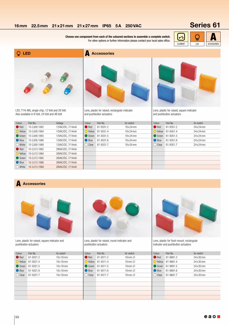
Lens, plastic for raised, square indicator and pushbutton actuators
Colour Part No. for switch
Red 61-9351.2 24 x 24 mm
Yellow 61-9351.4 24 x 24 mm
Green 61-9351.5 24 x 24 mm
Blue 61-9351.6 24 x 24 mm
Clear 61-9351.7 24 x 24 mm
Accessories
Lens, plastic for raised, rectangular indicator and pushbutton actuators
Colour Part No. for switch
Red 61-9331.2 18 x 24 mm
Yellow 61-9331.4 18 x 24 mm
Green 61-9331.5 18 x 24 mm
Blue 61-9331.6 18 x 24 mm
Clear 61-9331.7 18 x 24 mm
LED
LED, T1¾ MG, single chip, 12 Volt and 28 Volt. Also available in 6 Volt, 24 Volt and 48 Volt
Colour Part No. Voltage
Red 10-2J09.1062 12VAC/DC, 7/14mA
Yellow 10-2J09.1064 12VAC/DC, 7/14mA
Green 10-2J09.1065 12VAC/DC, 7/14mA
Blue 10-2J09.1066 12VAC/DC, 7/14mA
White 10-2J09.1069 12VAC/DC, 7/14mA
Red 10-2J13.1062 28VAC/DC, 7/14mA
Yellow 10-2J13.1064 28VAC/DC, 7/14mA
Green 10-2J13.1065 28VAC/DC, 7/14mA
Blue 10-2J13.1066 28VAC/DC, 7/14mA
White 10-2J13.1069 28VAC/DC, 7/14mA
Lens, plastic for raised, round indicator and pushbutton actuators
Colour Part No. for switch
Red 61-9311.2 18 mm ∅
Yellow 61-9311.4 18 mm ∅
Green 61-9311.5 18 mm ∅
Blue 61-9311.6 18 mm ∅
Clear 61-9311.7 18 mm ∅
Accessories
Lens, plastic for raised, square indicator and pushbutton actuators
Colour Part No. for switch
Red 61-9321.2 18 x 18 mm
Yellow 61-9321.4 18 x 18 mm
Green 61-9321.5 18 x 18 mm
Blue 61-9321.6 18 x 18 mm
Clear 61-9321.7 18 x 18 mm
Lens, plastic for flush mount, rectangular indicator and pushbutton actuators
Colour Part No. for switch
Red 61-9681.2 24 x 30 mm
Yellow 61-9681.4 24 x 30 mm
Green 61-9681.5 24 x 30 mm
Blue 61-9681.6 24 x 30 mm
Clear 61-9681.7 24 x 30 mm
100
1 2 3 41 2 3
1
2
3
4
Series 61 16 mm 22.5 mm 21 x 21 mm 21 x 27 mm IP65 5 A 250 VAC
Choose one component from each of the coloured sections to assemble a complete switch. For other options or further information please contact your local sales office.
INDICATOR pushbuTTON e-sTOp keylOCk seleCTOR
Lens, plastic for flush mount, square indicator and pushbutton actuators
Colour Part No. for switch
Red 61-9671.2 24 x 24 mm
Yellow 61-9671.4 24 x 24 mm
Green 61-9671.5 24 x 24 mm
Blue 61-9671.6 24 x 24 mm
Clear 61-9671.7 24 x 24 mm
Accessories
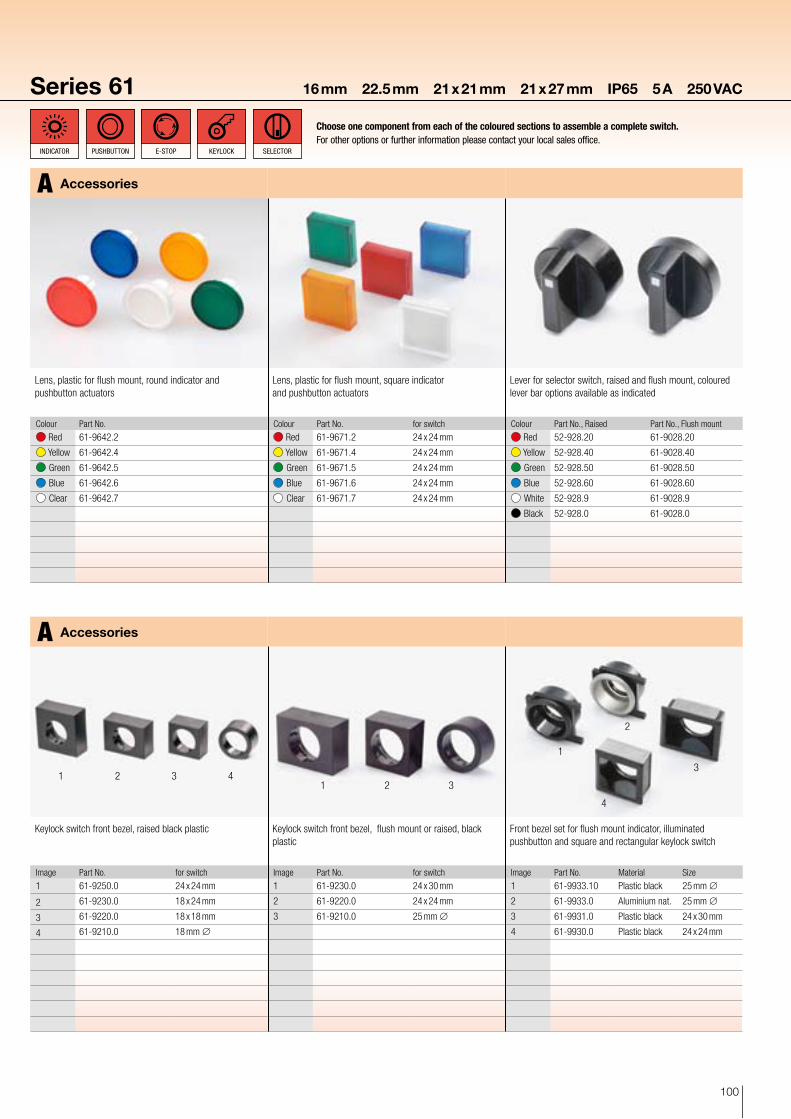
Lens, plastic for flush mount, round indicator and pushbutton actuators
Colour Part No.
Red 61-9642.2
Yellow 61-9642.4
Green 61-9642.5
Blue 61-9642.6
Clear 61-9642.7
Lever for selector switch, raised and flush mount, coloured lever bar options available as indicated
Colour Part No., Raised Part No., Flush mount
Red 52-928.20 61-9028.20
Yellow 52-928.40 61-9028.40
Green 52-928.50 61-9028.50
Blue 52-928.60 61-9028.60
White 52-928.9 61-9028.9
Black 52-928.0 61-9028.0
Accessories
Keylock switch front bezel, raised black plastic
Image Part No. for switch
1 61-9250.0 24 x 24 mm
2 61-9230.0 18 x 24 mm
3 61-9220.0 18 x 18 mm
4 61-9210.0 18 mm ∅
Keylock switch front bezel, flush mount or raised, black plastic
Image Part No. for switch
1 61-9230.0 24 x 30 mm
2 61-9220.0 24 x 24 mm
3 61-9210.0 25 mm ∅
Front bezel set for flush mount indicator, illuminated pushbutton and square and rectangular keylock switch
Image Part No. Material Size
1 61-9933.10 Plastic black 25 mm ∅
2 61-9933.0 Aluminium nat. 25 mm ∅
3 61-9931.0 Plastic black 24 x 30 mm
4 61-9930.0 Plastic black 24 x 24 mm
101
1 2 3
4 56
4 5 6
12 3
1
2
3
1 2
Series 6116 mm 22.5 mm 21 x 21 mm 21 x 27 mm IP65 5 A 250 VAC
eleMeNT leD ACCessORIes
Choose one component from each of the coloured sections to assemble a complete switch. For other options or further information please contact your local sales office.
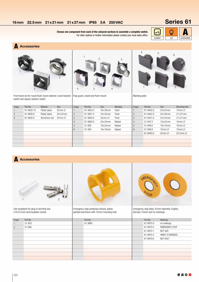
Flap guard, raised and flush mount
Image Part No. Size Mounting
1 61-9922.0 24 x 30 mm Flush
2 61-9921.0 24 x 24 mm Flush
3 61-9924.0 25 mm ∅ Flush
4 61-9920.0 24 x 24 mm Raised
5 51-925 18 x 24 mm Raised
6 51-920 18 x 18 mm Raised
Blanking plate
Image Part No. Size Mounting hole
1 61-9450.0 24 x 24 mm 16 mm ∅
2 61-9452.0 24 x 30 mm 21 x 27 mm
3 61-9451.0 24 x 24 mm 21 x 21 mm
4 51-947.0 18 x 24 mm 16 mm ∅
5 51-948.0 18 x 18 mm 16 mm ∅
6 51-949.0 18 mm ∅ 16 mm ∅
61-9453.0 25 mm ∅ 22.5 mm ∅
Front bezel set for round flush mount selector, round keylock switch and square selector switch
Image Part No. Material Size
1 61-9932.10 Plastic black 25 mm ∅
2 61-9936.0 Plastic black 24 x 24 mm
3 61-9932.0 Aluminium nat. 25 mm ∅
Accessories
Accessories
Flat receptacle for plug-in terminal size 2.8 x 0.5 mm and insulation socket
Image Part No.
1 31-929
2 31-946
Emergency-stop protective shroud, yellow painted aluminium with 16 mm mounting hole
Part No.
61-9965
Emergency-stop label, 43 mm diameter, English, German, French and no markings
Part No. Markings
61-9970.0 no markings
61-9970.2 EMERGENCY STOP
61-9970.1 NOT AUS
61-9970.3 ARRET D’URGENCE
61-9970.6 NOT-HALT
102
1 2 132
1 2
3 4
5
Series 61 16 mm 22.5 mm 21 x 21 mm 21 x 27 mm IP65 5 A 250 VAC
Choose one component from each of the coloured sections to assemble a complete switch. For other options or further information please contact your local sales office.
INDICATOR pushbuTTON e-sTOp keylOCk seleCTOR
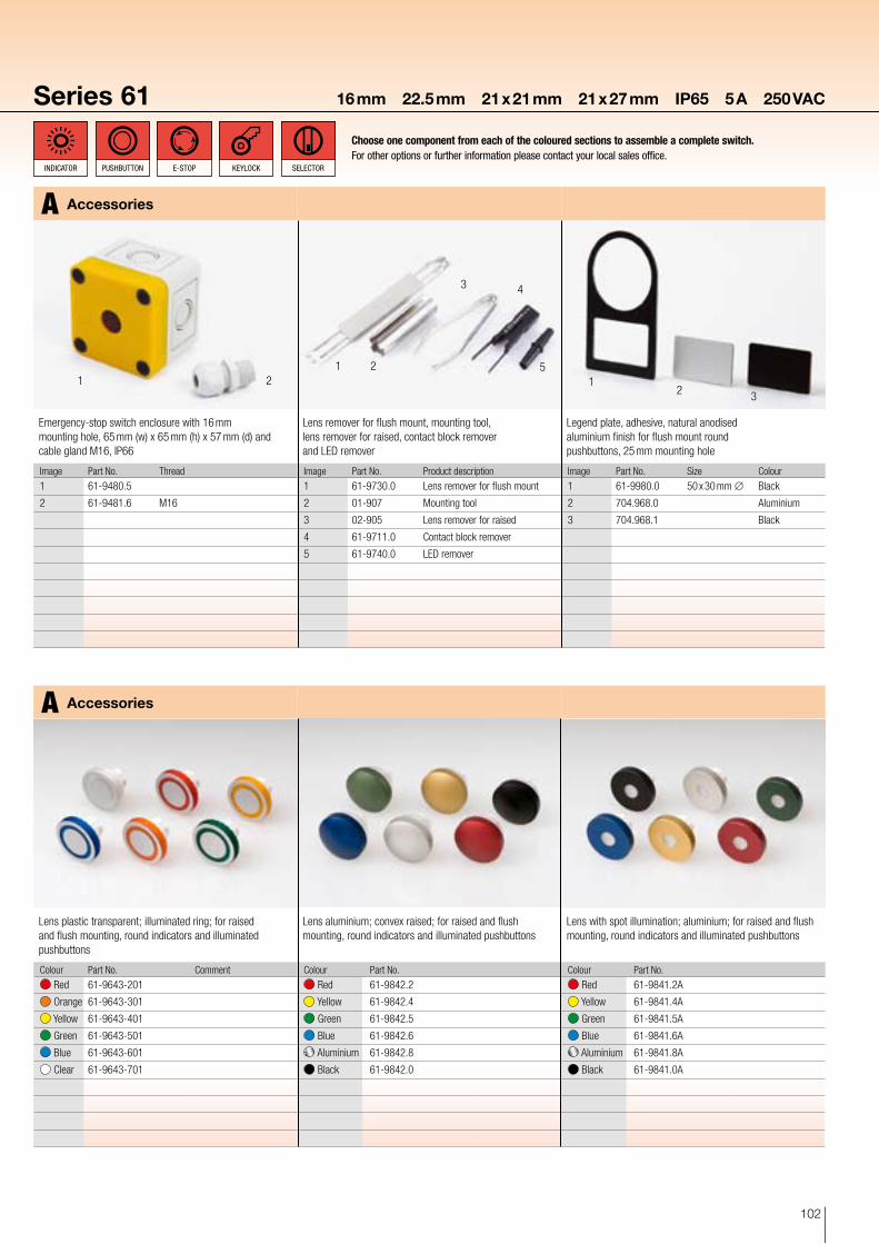
Lens remover for flush mount, mounting tool, lens remover for raised, contact block remover and LED remover
Image Part No. Product description
1 61-9730.0 Lens remover for flush mount
2 01-907 Mounting tool
3 02-905 Lens remover for raised
4 61-9711.0 Contact block remover
5 61-9740.0 LED remover
Legend plate, adhesive, natural anodised aluminium finish for flush mount round pushbuttons, 25 mm mounting hole
Image Part No. Size Colour
1 61-9980.0 50 x 30 mm ∅ Black
2 704.968.0 Aluminium
3 704.968.1 Black
Emergency-stop switch enclosure with 16 mm mounting hole, 65 mm (w) x 65 mm (h) x 57 mm (d) and cable gland M16, IP66
Image Part No. Thread
1 61-9480.5
2 61-9481.6 M16
Accessories
Accessories
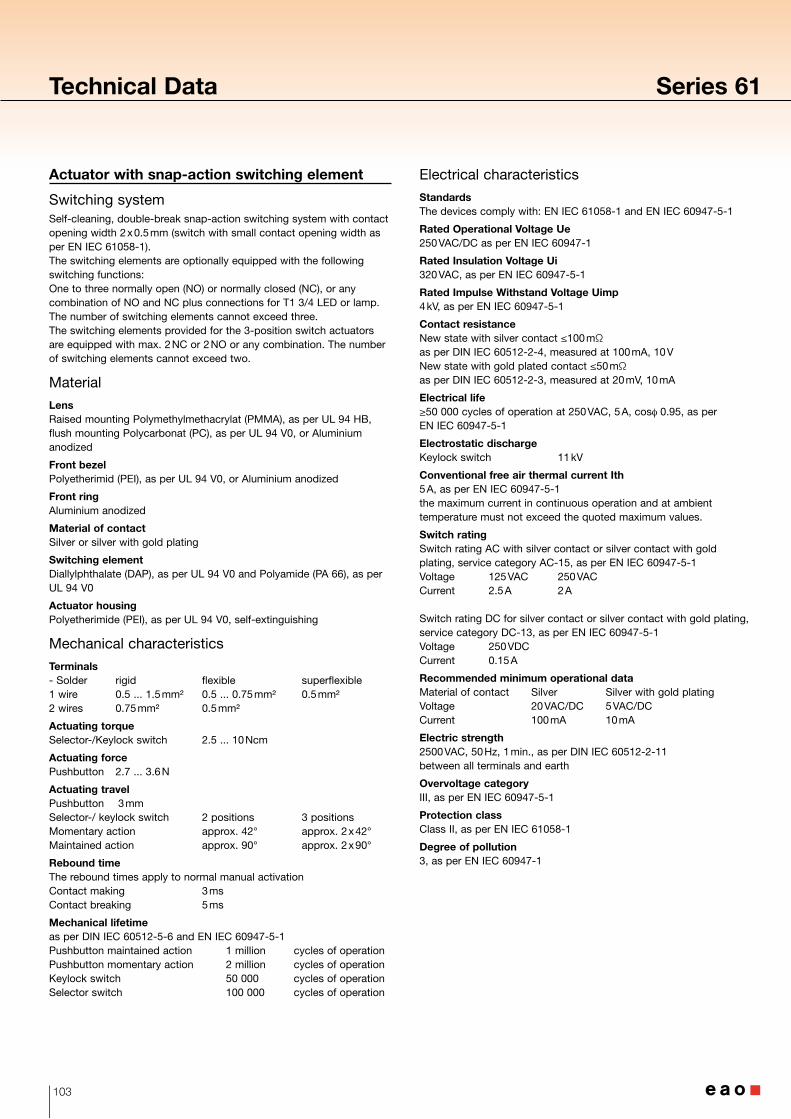
Lens plastic transparent; illuminated ring; for raised and flush mounting, round indicators and illuminated pushbuttons
Colour Part No. Comment
Red 61-9643-201
Orange 61-9643-301
Yellow 61-9643-401
Green 61-9643-501
Blue 61-9643-601
Clear 61-9643-701
Lens aluminium; convex raised; for raised and flush mounting, round indicators and illuminated pushbuttons
Colour Part No.
Red 61-9842.2
Yellow 61-9842.4
Green 61-9842.5
Blue 61-9842.6
Aluminium 61-9842.8
Black 61-9842.0
Lens with spot illumination; aluminium; for raised and flush mounting, round indicators and illuminated pushbuttons
Colour Part No.
Red 61-9841.2A
Yellow 61-9841.4A
Green 61-9841.5A
Blue 61-9841.6A
Aluminium 61-9841.8A
Black 61-9841.0A
103
Technical Data Series 61
Actuator with snap-action switching element
Switching systemSelf-cleaning, double-break snap-action switching system with contact opening width 2 x 0.5 mm (switch with small contact opening width as per EN IEC 61058-1). The switching elements are optionally equipped with the following switching functions:One to three normally open (NO) or normally closed (NC), or any combination of NO and NC plus connections for T1 3/4 LED or lamp. The number of switching elements cannot exceed three.The switching elements provided for the 3-position switch actuators are equipped with max. 2 NC or 2 NO or any combination. The number of switching elements cannot exceed two.
Material
LensRaised mounting Polymethylmethacrylat (PMMA), as per UL 94 HB, flush mounting Polycarbonat (PC), as per UL 94 V0, or Aluminium anodized
Front bezelPolyetherimid (PEI), as per UL 94 V0, or Aluminium anodized
Front ringAluminium anodized
Material of contactSilver or silver with gold plating
Switching elementDiallylphthalate (DAP), as per UL 94 V0 and Polyamide (PA 66), as per UL 94 V0
Actuator housingPolyetherimide (PEI), as per UL 94 V0, self-extinguishing
Mechanical characteristics
Terminals- Solder rigid flexible superflexible1 wire 0.5 ... 1.5 mm² 0.5 ... 0.75 mm² 0.5 mm²2 wires 0.75 mm² 0.5 mm²
Actuating torqueSelector-/Keylock switch 2.5 ... 10 Ncm
Actuating forcePushbutton 2.7 ... 3.6 N
Actuating travelPushbutton 3 mmSelector-/ keylock switch 2 positions 3 positionsMomentary action approx. 42° approx. 2 x 42°Maintained action approx. 90° approx. 2 x 90°
Rebound timeThe rebound times apply to normal manual activationContact making 3 msContact breaking 5 ms
Mechanical lifetimeas per DIN IEC 60512-5-6 and EN IEC 60947-5-1Pushbutton maintained action 1 million cycles of operationPushbutton momentary action 2 million cycles of operationKeylock switch 50 000 cycles of operationSelector switch 100 000 cycles of operation
Electrical characteristics
StandardsThe devices comply with: EN IEC 61058-1 and EN IEC 60947-5-1
Rated Operational Voltage Ue250 VAC/DC as per EN IEC 60947-1
Rated Insulation Voltage Ui320 VAC, as per EN IEC 60947-5-1
Rated Impulse Withstand Voltage Uimp4 kV, as per EN IEC 60947-5-1
Contact resistanceNew state with silver contact ≤100 mΩ as per DIN IEC 60512-2-4, measured at 100 mA, 10 V New state with gold plated contact ≤50 mΩ as per DIN IEC 60512-2-3, measured at 20 mV, 10 mA
Electrical life≥50 000 cycles of operation at 250 VAC, 5 A, cosφ 0.95, as per EN IEC 60947-5-1
Electrostatic dischargeKeylock switch 11 kV
Conventional free air thermal current Ith5 A, as per EN IEC 60947-5-1 the maximum current in continuous operation and at ambient temperature must not exceed the quoted maximum values.
Switch ratingSwitch rating AC with silver contact or silver contact with gold plating, service category AC-15, as per EN IEC 60947-5-1Voltage 125 VAC 250 VACCurrent 2.5 A 2 A Switch rating DC for silver contact or silver contact with gold plating, service category DC-13, as per EN IEC 60947-5-1Voltage 250 VDCCurrent 0.15 A
Recommended minimum operational dataMaterial of contact Silver Silver with gold platingVoltage 20 VAC/DC 5 VAC/DCCurrent 100 mA 10 mA
Electric strength2500 VAC, 50 Hz, 1 min., as per DIN IEC 60512-2-11 between all terminals and earth
Overvoltage categoryIII, as per EN IEC 60947-5-1
Protection classClass II, as per EN IEC 61058-1
Degree of pollution3, as per EN IEC 60947-1
104
Series 61 Technical Data
Environmental conditions
Storage temperature−40 °C ... +85 °C
Operating temperature−25 °C ... +55 °C
Protection degreeas per EN IEC 60529Frontside IP65 | rear side IP40
Shock resistance(semi-sinusoidal) max. 100 m/s², pulse width 11 ms, 3-axis, as per EN IEC 60068-2-27
Vibration resistance(sinusoidal) max. 100 m/s² at 10 Hz ... 500 Hz, as per EN IEC 60068-2-6
Climate resistanceDamp heat, cyclic 96 hours, +25 °C / 97%, +55 °C / 93% relative humidity, as per EN IEC 60068-2-30
Damp heat, state 56 days, +40 °C / 93% relative humidity, as per EN IEC 60068-2-78
Rapid change of temperature 100 cycles, −40 °C ... +80 °C, as per EN IEC 60068-2-14
Approvals
ApprobationsCB (IEC 60947)CB (IEC 61058)CSAENEC (EN 61058)Germanischer LloydGOSTULVDE
Declaration of conformityCE
Actuator with slow-make switching element
Switching systemDouble-break slow-make system, contact opening width 2 x 1.5 mm, with 2 x 2 contact points per switching element. NC-contact elements in the slow-make elements fulfill requirements of switches with forced opening as per EN IEC 60947-5-1 2.17The slow-make elements are optionally obtainable with the following switching functions: 1 NO or 2 NO, 1 NC or 2 NC, 1 NO + 1 NC.
Material
LensRaised mounting Polymethylmethacrylat (PMMA), as per UL 94 HB, flush mounting Polycarbonat (PC), as per UL 94 V0, or Aluminium anodized
Front bezelPolyetherimid (PEI), as per UL 94 V0, or Aluminium anodized
Front ringAluminium anodized
Material of contactSilver or gold (specified for operation for low level switching)
Switching elementDiallylphthalate (DAP), as per UL 94 V0 and Polyamide (PA 66), as per UL 94 V0
Actuator housingPolyetherimide (PEI), as per UL 94 V0, self-extinguishing
Mechanical characteristics
Terminals- Solder rigid flexible superflexible1 wire 0.5 ... 1.5 mm² 0.5 ... 0.75 mm² 0.5 mm²2 wires 0.75 mm² 0.5 mm²
- Screw 1 wire 0.5 ... 1.5 mm² 0.5 ... 0.75 mm² 0.5 mm²2 wires 0.75 mm² 0.5 mm² 0.5 mm²
Actuating torqueSelector-/ Keylock switch 4 ... 16 Ncm
Actuating forcePushbutton 3.5 ... 11 NEmergency-stop switch max. 65 N
Actuating travelPushbutton 3 mmEmergency-stop switch 10 mm
Selector-/ keylock switch 2 positions 3 positionsMomentary action approx. 42° approx. 2 x 42°Maintained action approx. 90° approx. 2 x 90°
Rebound time2 ms, contact making and contact breakingthe rebound times apply to normal manual activation
Mechanical lifetimeas per DIN IEC 60512-5-6 and EN IEC 60947-5-1Pushbutton maintained action 1 million cycles of operationPushbutton momentary action 2 million cycles of operationEmergency-stop pushbutton 6 050 cycles of operationKeylock switch 50 000 cycles of operationSelector switch 100 000 cycles of operation
105
Technical Data Series 61
Electrical characteristics
StandardsThe devices comply with: EN IEC 61058-1 and EN IEC 60947-5-1, EN IEC 60947-5-5 (Emergency-stop)
Electrical life≥50 000 cycles of operation at 250 VAC, 5 A, cosφ 0.95, as per EN IEC 60947-5-1Switching Element of Emergency-stop 6050 cycles of operation, as per EN IEC 60947-5-5
Electrostatic dischargeKeylock switch 11 kV
Electric strength4000 VAC, 50 Hz, 1 min., as per DIN IEC 60512-2 between all terminals and earth
Overvoltage categoryIII, as per EN IEC 60947-5-1
Protection classClass II, as per EN IEC 61058-1
Degree of pollution3, as per EN IEC 60947-1
Electrical characteristics for silver contacts
Rated Operational Voltage Ue250 VAC/DC as per EN IEC 60947-1
Rated Insulation Voltage Ui320 VAC, as per EN IEC 60947-5-1
Rated Impulse Withstand Voltage Uimp4 kV, as per EN IEC 60947-5-1
Contact resistanceNew state ≤50 mΩ, as per DIN IEC 60512-2-4, measured at 100 mA, 10 V
Conventional free air thermal current Ith5 A, as per EN IEC 60947-5-1 the maximum current in continuous operation and at ambient temperature must not exceed the quoted maximum values.
Switch ratingSwitch rating AC with silver contact and srew terminal, service category AC-15, as per EN IEC 60947-5-1Voltage 125 VAC 250 VACCurrent 3 A 2 A
Switch rating with silver contact and screw terminal, service category DC-13, as per EN IEC 60947-5-1Voltage 250 VDCCurrent 0.2 A
Recommended minimum operational data20 VAC/DC, 100 mA
106
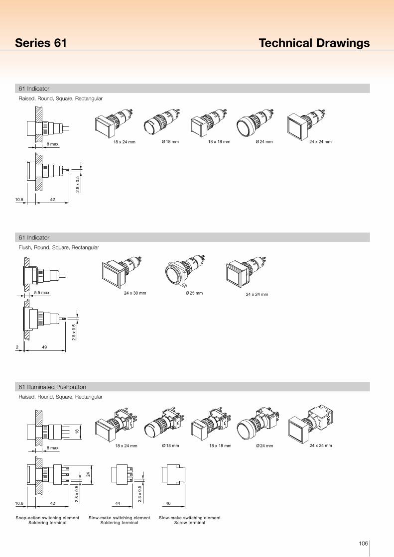
Ø 24 mm 24 x 24 mmØ 18 mm 18 x 18 mm18 x 24 mm
2.8
x 0.
5
8 max.
10.6 42
Ø 25 mm 24 x 24 mm24 x 30 mm5.5 max.
2 49
2.8
x 0.
5
Series 61 Technical Drawings
Raised, Round, Square, Rectangular
Flush, Round, Square, Rectangular
Raised, Round, Square, Rectangular
61 Indicator
61 Indicator
61 Illuminated Pushbutton
Snap-action switching elementSoldering terminal
Slow-make switching elementScrew terminal
Slow-make switching elementSoldering terminal
Ø 24 mm 24 x 24 mmØ 18 mm 18 x 18 mm18 x 24 mm
10.6 42 4644 2.8
x 0.
5
2.8
x 0.
5
24
8 max.
18
107
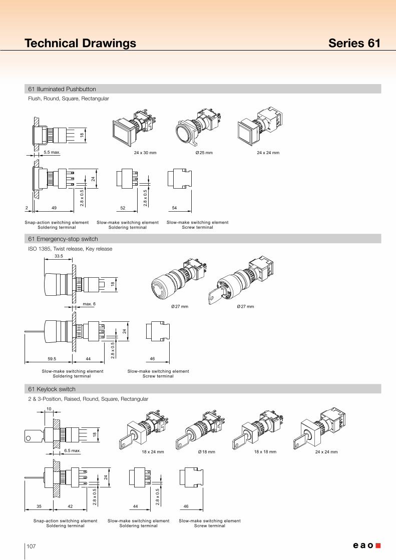
Technical Drawings Series 61
ISO 1385, Twist release, Key release
Flush, Round, Square, Rectangular
2 & 3-Position, Raised, Round, Square, Rectangular
61 Emergency-stop switch
61 Illuminated Pushbutton
61 Keylock switch
Snap-action switching elementSoldering terminal
Slow-make switching elementScrew terminal
Slow-make switching elementSoldering terminal
5.5 max.
2 49 54
2.8
x 0.
5
2.8
x 0.
5
24
18
52
Ø 25 mm 24 x 24 mm24 x 30 mm
Ø 27 mm Ø 27 mm
Slow-make switching elementSoldering terminal
Slow-make switching elementScrew terminal
59.5 44 462.8
x 0.
5
24
33.5
18
max. 6
Snap-action switching elementSoldering terminal
Slow-make switching elementScrew terminal
Slow-make switching elementSoldering terminal
35 42 4644 2.8
x 0.
5
2.8
x 0.
5
24
6.5 max.
18
24 x 24 mmØ 18 mm 18 x 18 mm18 x 24 mm
10
108
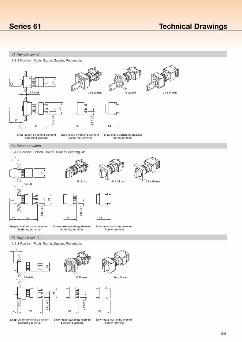
Series 61 Technical Drawings
2 & 3-Position, Flush, Round, Square, Rectangular
2 & 3-Position, Raised, Round, Square, Rectangular
2 & 3-Position, Flush, Round, Square, Rectangular
61 Keylock switch
61 Selector switch
61 Keylock switch
Snap-action switching elementSoldering terminal
Slow-make switching elementScrew terminal
Slow-make switching elementSoldering terminal
Ø 25 mm 24 x 24 mm24 x 30 mm
49
27
2 2.8
x 0.
5
2.8
x 0.
5
24
5.5 max.
18
5452
Snap-action switching elementSoldering terminal
Slow-make switching elementSoldering terminal
Slow-make switching elementScrew terminal
Ø 18 mm 26 x 26 mm24 x 24 mm
44 464214
2.8
x 0.
5
2.8
x 0.
5
24
max. 8
18
7
Snap-action switching elementSoldering terminal
Slow-make switching elementScrew terminal
Slow-make switching elementSoldering terminal
Ø 25 mm 24 x 24 mm5.5 max.
2 49 54
24
18
51
7
2.8
x 0.
5
2.8
x 0.
5
109
16+0.2 0
1.7 0
-0
.1
Ø32 = 35 min.Ø27 = 45 min.
Ø32
= 3
2 m
in.
Ø27
= 4
5 m
in.
15+0.05 0
Ø 27 mm
Ø 32 mm
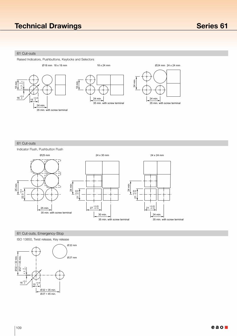
Technical Drawings Series 61
Raised Indicators, Pushbuttons, Keylocks and Selectors
Indicator Flush, Pushbutton Flush
ISO 13850, Twist release, Key release
61 Cut-outs
61 Cut-outs
61 Cut-outs, Emergency-Stop
Ø18 mm 18 x 18 mm Ø24 mm18 x 24 mm 24 x 24 mm
15+0.05 0
24 min.
35 min. with screw terminal
35 min. with screw terminal 35 min. with screw terminal
18 m
in.
18 m
in.
24 m
in.
24 min.24 min.16+0.2 0
1.7 0
-0
.1
25 min.
30 min.
24 m
in.
25 m
in.
Ø25 mm
22.3
+0.4
0
27+0.25 -0.15
21+0
.25
-0
.15
24 min.
24 m
in.
24 x 30 mm 24 x 24 mm
21+0.25 -0.15
21+0
.25
-0
.15
35 min. with screw terminal
35 min. with screw terminal 35 min. with screw terminal