Embed Size (px)
Citation preview

SERIES 35-150SOLUTION TANK SYSTEMBOOK NO. IM 350.150AA UA ISSUE A

IM 350.150AA UA (A/4-02)
SERIES 35-150 SOLUTION TANK SYSTEM
EQUIPMENT SERIAL NO. _________________
DATE OF START-UP _____________________
START-UP BY ___________________________
Prompt service available from nationwide authorized service contractors.
ORDERING INFORMATION
In order for us to fill your order immediately and correctly, please order material by description and part number, as shown inthis book. Also, please specify the serial number of the equipment on which the parts will be installed.
WARRANTY
Seller warrants for a period of one year after shipment that the equipment or material of its manufacture is free from defectsin workmanship and materials. Corrosion or other decomposition by chemical action is specifically excluded as a defectcovered hereunder, except this exclusion shall not apply to chlorination equipment. Seller does not warrant (a) damagecaused by use of the items for purposes other than those for which they were designed, (b) damage caused by unauthorizedattachments or modifications, (c) products subject to any abuse, misuse, negligence or accident, (d) products where partsnot made, supplied, or approved by Seller are used and in the sole judgement of the Seller such use affects the products’performance, stability or reliability, and (e) products that have been altered or repaired in a manner in which, in the solejudgement of Seller, affects the products’ performance, stability or reliability. SELLER MAKES NO OTHER WARRANTY OFANY KIND, AND THE FOREGOING WARRANTY IS IN LIEU OF ALL OTHER WARRANTIES, EXPRESS OR IMPLIED,INCLUDING ANY WARRANTY OF MERCHANTABILITY OR OF FITNESS OF THE MATERIAL OR EQUIPMENT FORANY PARTICULAR PURPOSE EVEN IF THAT PURPOSE IS KNOWN TO SELLER. If Buyer discovers a defect in materialor workmanship, it must promptly notify Seller in writing; Seller reserves the right to require the return of such defective partsto Seller, transportation charges prepaid, to verify such defect before this warranty is applicable. In no event shall suchnotification be received by Seller later than 13 months after the date of shipment. No action for breach of warranty shall bebrought more than 15 months after the date of shipment of the equipment or material.
LIMITATION OF BUYER’S REMEDIES. The EXCLUSIVE REMEDY for any breach of warranty is the replacement f.o.b.shipping point of the defective part or parts of the material or equipment. Any equipment or material repaired or replacedunder warranty shall carry the balance of the original warranty period, or a minimum of three months. Seller shall not be liablefor any liquidated, special, incidental or consequential damages, including without limitation, loss of profits, loss of savings orrevenue, loss of use of the material or equipment or any associated material or equipment, the cost of substitute material orequipment, claims of third parties, damage to property, or goodwill, whether based upon breach of warranty, breach ofcontract, negligence, strict tort, or any other legal theory; provided, however, that such limitation shall not apply to claims forpersonal injury.
Statements and instructions set forth herein are based upon the best information and practices known to U.S. Filter/Wallace& Tiernan, Inc., but it should not be assumed that every acceptable safety procedure is contained herein. Of necessity thiscompany cannot guarantee that actions in accordance with such statements and instructions will result in the completeelimination of hazards and it assumes no liability for accidents that may occur.
1.010-42D
WALLACE & TIERNAN PRODUCTS1901 West Garden Road, Vineland, NJ 08360
IM 350.150AA UA (A/4-02)
SERIES 35-150 SOLUTION TANK SYSTEM
Introd.
!
INTRODUCTION
The USFilter’s Wallace & Tiernan Products (USF/W&T) Series 35-150Solution Tank Systems described in this Instruction Book have beendesigned for automatically and accurately feeding dry chemicals to pre-pare chemical solutions for water and waste treatment applications.
The USF/W&T Series 32-055 Feeder (which is a part of this system) isdescribed in a separate Instruction Book provided with the equipment.Disregard the feeder wiring instructions covered in the feeder book sincethe complete tank system wiring is described in this system book.
This Instruction Book consists of Technical Data, Installation, Operation,Service, and Parts information for all other components of the system.Although it is as specific as possible, there may be some details that do notapply to the equipment supplied.
WARNING: TO AVOID POSSIBLE SEVERE PERSONAL INJURYOR DAMAGE TO EQUIPMENT, THIS EQUIPMENT SHOULDBE INSTALLED, OPERATED, AND SERVICED ONLY BYTRAINED, QUALIFIED PERSONNEL WHO ARE THOR-OUGHLY FAMILIAR WITH THE ENTIRE CONTENTS OF THISINSTRUCTION BOOK.
NOTE: When ordering material always specify model and serial num-ber of apparatus
TABLE OF CONTENTS
Very Important Safety Precautions .......................... SP-1, -2Regional Offices ....................................................... 1.010-1Technical Data .......................................................... Section 1Installation ................................................................ Section 2Operation .................................................................. Section 3Service ...................................................................... Section 4Illustrations ............................................................... Section 5Spare Parts List ......................................................... Section 6Vendor Literature ..................................................... Section 7
Torit Dust Collector ............................................... CAB-01M
IM 350.150AA UA (A/4-02)
SERIES 35-150 SOLUTION TANK SYSTEM
SP-1
VERY IMPORTANT SAFETY PRECAUTIONS
This page provides, in brief, information of urgent importance relative to safety in the installation,operation, and maintenance of this equipment.
WARNING
TO AVOID POSSIBLE SEVERE PERSONAL INJURY, OBSERVE THE FOLLOWING PRECAU-TIONS:
DO NOT USE ELECTRIC VIBRATOR IN HAZARDOUS LOCATIONS.
TO AVOID CONTACT WITH HAZARDOUS MATERIAL, WHEN WORKING WITH HAZARD-OUS MATERIAL, IT IS THE RESPONSIBILITY OF THE EQUIPMENT USER TO OBTAIN ANDOBSERVE ALL SAFETY PRECAUTIONS OF THE MATERIAL MANUFACTURER/SUPPLIER.
FOR OVERHEAD FLOOR SUPPORTED HOPPERING, THE TOTAL WEIGHT OF HOPPERS,BAG LOADER, OR DUST COLLECTOR AND CHEMICAL MUST NOT EXCEED THE MAXI-MUM ALLOWABLE FLOOR LOADING. FOR STAND SUPPORTED HOPPERING, THE TOTALWEIGHT OF HOPPERING BAG LOADER OR DUST COLLECTOR AND CHEMICAL MUST NOTEXCEED 3000 LBS. FOR FEEDER SUPPORTED HOPPERING, THE TOTAL WEIGHT OF HOP-PERS AND CHEMICAL MUST NOT EXCEED 1000 LBS. INSTALL ADEQUATE STABILIZINGSTRUCTURES WHEN HOPPERS ARE FREE STANDING.
DO NOT OPERATE WITHOUT SHAFT GUARD IN PLACE.
TO AVOID POSSIBLE ELECTRICAL SHOCK, TURN POWER OFF BEFORE SERVICING.
TO ENSURE PROPER AND SAFE OPERATION OF THIS EQUIPMENT, USE ONLY USF/W&TLISTED PARTS EXCEPT COMMERCIALLY AVAILABLE PARTS AS IDENTIFIED BY COM-PLETE DESCRIPTION ON PARTS LIST. THE USE OF UNLISTED PARTS CAN RESULT INEQUIPMENT MALFUNCTIONS CAUSING POSSIBLE SEVERE PERSONAL INJURY.
DO NOT DISCARD THIS INSTRUCTION BOOK UPON COMPLETION OF INSTALLATION.INFORMATION PROVIDED IS ESSENTIAL TO PROPER AND SAFE OPERATION AND MAIN-TENANCE.
ADDITIONAL OR REPLACEMENT COPIES OF THIS INSTRUCTION BOOK ARE AVAILABLEFROM:
USFILTER’S WALLACE & TIERNAN PRODUCTS1901 WEST GARDEN ROADVINELAND, NJ 08360PHONE: (856) 507-9000FAX: (856) 507-4125
IM 350.150AA UA (A/4-02)
SERIES 35-150 SOLUTION TANK SYSTEM
SP-2
VERY IMPORTANT SAFETY PRECAUTIONS (CONT’D)
NOTE
Minor part number changes may be incorporated into USF/W&T products from time to time that are notimmediately reflected in the Instruction Book. If such a change apparently has been made in yourequipment and does not appear to be reflected in your instruction book, contact your local USF/W&Tsales office for information.
Please include the equipment serial number in all correspondence. It is essential for effective commu-nication and proper equipment identification.
IM 350.150AA UA (A/4-02)
SERIES 35-150 SOLUTION TANK SYSTEM
REGIONAL OFFICES
INSTALLATION, OPERATION, MAINTENANCE, AND SERVICE INFORMATION
Direct any questions concerning this equipment that are not answered in the instruction book to theReseller from whom the equipment was purchased. If the equipment was purchased directly fromUSFilter's Wallace & Tiernan Products (USF/W&T), contact the office indicated below.
UNITED STATES
1901 West Garden RoadVineland, NJ 08360TEL: (856) 507-9000FAX: (856) 507-4125
CANADA
If the equipment was purchased directly from USF/W&T Canada, contact the nearest office indicatedbelow.
ONTARIO QUEBEC
250 Royal Crest Court 243 Blvd. BrienMarkham, Ontario Bureau 210L3R3S1 Repentigny, Quebec(905) 944-2800 (514) 582-4266
MEXICO
If the equipment was purchased directly from USF/W&T de Mexico, contact the office indicated be-low.
Via Jose Lopez Portillo 321Col. Sta. Maria CuautepecTultitlan, Edo. de Mexico54900 MexicoTEL: 525 879 0260FAX: 525 875 2171
1.010-1D
1IM 350.150AA UA (A/4-02)
SERIES 35-150 SOLUTION TANK SYSTEM
SECTION 1 - TECHNICAL DATA
List Of Contents
PARA./DWG. NO.
Technical Data .......................................................... 1.1Illustrations
Performance ........................................................... 320.120.190.011Performance ........................................................... 350.100.190.010Performance ........................................................... 350.100.190.020
2IM 350.150AA UA (A/4-02)
SERIES 35-150 SOLUTION TANK SYSTEM
1.1 Technical Data
stnemeriuqeRrewoPlenaPlortnoC
dradnatSlanoitpO
srotoMrotatigAdradnatSlanoitpO
suodrazaHroF:noitacoL
redeeF
erepma51esahp-elgniszH06caV511esahp-3zH06caV064/032
esahp-1zH06caV032/511noitcudnipH4/1esahp-3zH06caV044/022noitcudnipH4/1
)GdnaFpuorG1.viDIIssalC(esahp-1zH06caV032/511noitcudnipH4/1esahp-3zH06caV064/032noitcudnipH4/1esahp-3zH06caV083/022noitcudnipH4/1
.redeeF550-23seireSrofkoobnoitcurtsnieeS
spmA.L.F6.2/2.555./1.1
6.2/2.555./1.157./3.1
lenaPlortnoC erusolcne21AMEN
xoBnoitcnuJredeeF GdnaFpuorG1.viD,IIssalClanoitporodradnats-21AMEN
srotarbiVcirtcelE
.tf.uc8-yticapaC,02VnortnySsnot2/1-3-yticapaC,15VnortnyS
snot5-yticapaC,05VnortnyScitamuenP
.tf.uc52-yticapaC,0511ledoMsnot02-01-yticapaC,0031ledoMsnot05-02-yticapaC,0531ledoM
zH06caV511
.sserPriAisp06isp06isp06
spmA0.20.70.7
noitpmusnoCriAmfc7mfc51mfc32
sttaW04001001
.qerFmpc0084mpc0003mpc0032
-noisolpxeeerhtdnadradnatseerhT:srotarbivcitamuenpehtrofsevlavdionelosxiseraerehT.G,F,EspuorG1.viD,IIssalCroffoorp
rotarbiVroF0511ledoM0031ledoM0531ledoM
rof.d'qeRrewoPevlaVdioneloS
)W5.01(zH06caV011)W5.01(zH06caV011
)W6(zH06caV011
noitcennoCTPN4/1TPN8/3TPN2/1
.sserPgnitarepO.xaMisp001isp001isp002
3IM 350.150AA UA (A/4-02)
SERIES 35-150 SOLUTION TANK SYSTEM
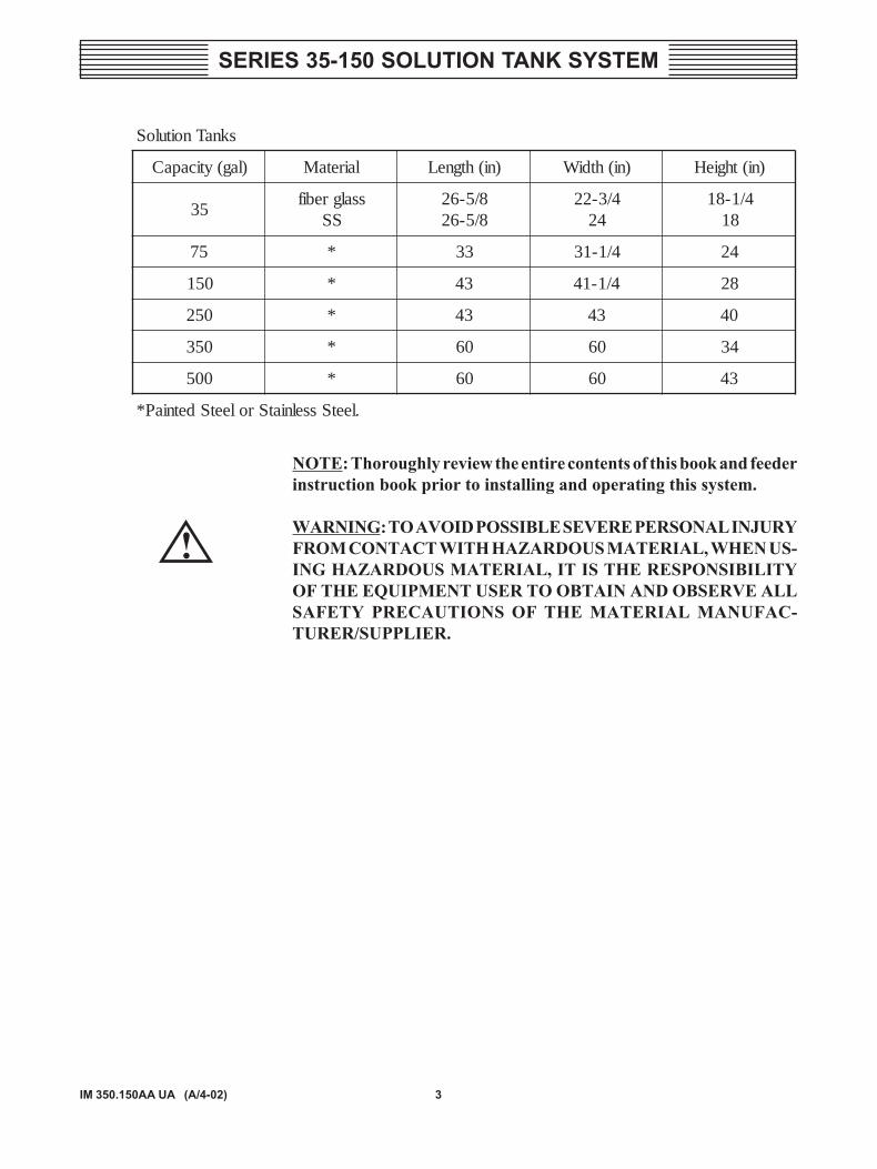
NOTE: Thoroughly review the entire contents of this book and feederinstruction book prior to installing and operating this system.
WARNING: TO AVOID POSSIBLE SEVERE PERSONAL INJURYFROM CONTACT WITH HAZARDOUS MATERIAL, WHEN US-ING HAZARDOUS MATERIAL, IT IS THE RESPONSIBILITYOF THE EQUIPMENT USER TO OBTAIN AND OBSERVE ALLSAFETY PRECAUTIONS OF THE MATERIAL MANUFAC-TURER/SUPPLIER.
sknaTnoituloS
)lag(yticapaC lairetaM )ni(htgneL )ni(htdiW )ni(thgieH
53ssalgrebif
SS8/5-628/5-62
4/3-2242
4/1-8181
57 * 33 4/1-13 42
051 * 34 4/1-14 82
052 * 34 34 04
053 * 06 06 43
005 * 06 06 34
.leetSsselniatSroleetSdetniaP*
!
4IM 350.150AA UA (A/4-02)
SERIES 35-150 SOLUTION TANK SYSTEM
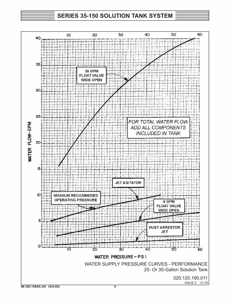
WATER SUPPLY PRESSURE CURVES - PERFORMANCE25- Or 35-Gallon Solution Tank
320.120.190.011ISSUE 2 12-78
5IM 350.150AA UA (A/4-02)
SERIES 35-150 SOLUTION TANK SYSTEM
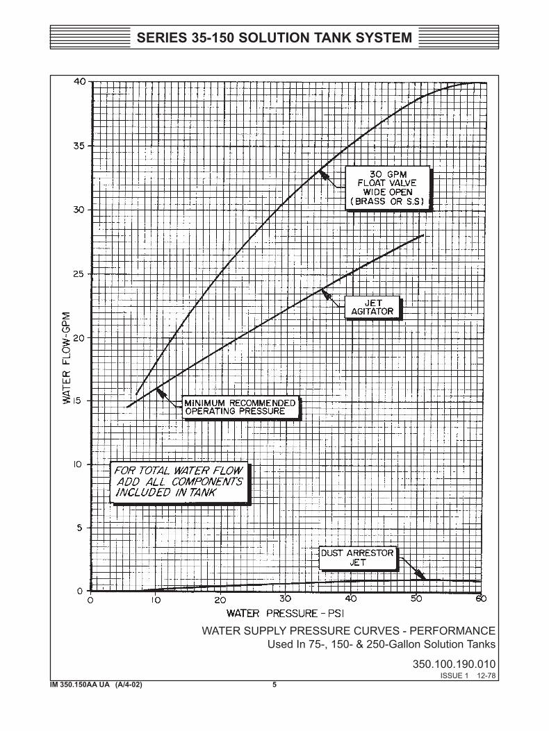
WATER SUPPLY PRESSURE CURVES - PERFORMANCEUsed In 75-, 150- & 250-Gallon Solution Tanks
350.100.190.010ISSUE 1 12-78
6IM 350.150AA UA (A/4-02)
SERIES 35-150 SOLUTION TANK SYSTEM
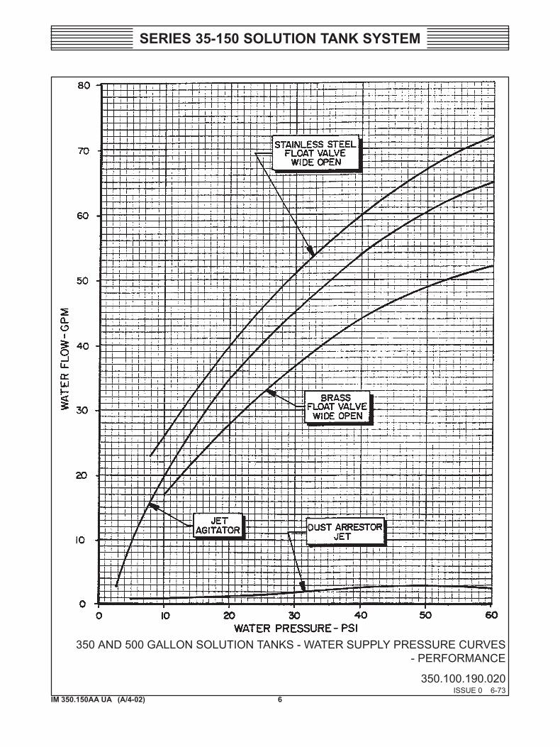
350 AND 500 GALLON SOLUTION TANKS - WATER SUPPLY PRESSURE CURVES - PERFORMANCE
350.100.190.020ISSUE 0 6-73
7IM 350.150AA UA (A/4-02)
SERIES 35-150 SOLUTION TANK SYSTEM
SECTION 2 - INSTALLATION
List Of Contents
PARA./DWG. NO.
General ..................................................................... 2.1Location and Basic Installation ................................ 2.2
Feeder on Solution Tank ....................................... 2.2.1Feeder on Stand Alongside Solution Tank ............ 2.2.2Flexible Connection and Shut-Off Gate ................ 2.2.3Hoppers .................................................................. 2.2.4Vibrators ................................................................ 2.2.5Connections ........................................................... 2.2.6
IllustrationsTypical Installation ................................................ 350.150.110.010Typical Installation ................................................ 350.150.110.040Typical Installation ................................................ 350.150.110.050Typical Installation ................................................ 350.150.110.060Installation Piping .................................................. 350.150.120.010
8IM 350.150AA UA (A/4-02)
SERIES 35-150 SOLUTION TANK SYSTEM
2.1 General
There are two general types of systems: feeder mounted directly on top ofsolution tank and feeder mounted on floor-supported stand.
The tank-mounted feeder system is completely assembled and prewired.Any hoppers to be mounted above the feeder are packaged separately andmust be field installed. See Dwg. 350.150.110.010 for typical systems.
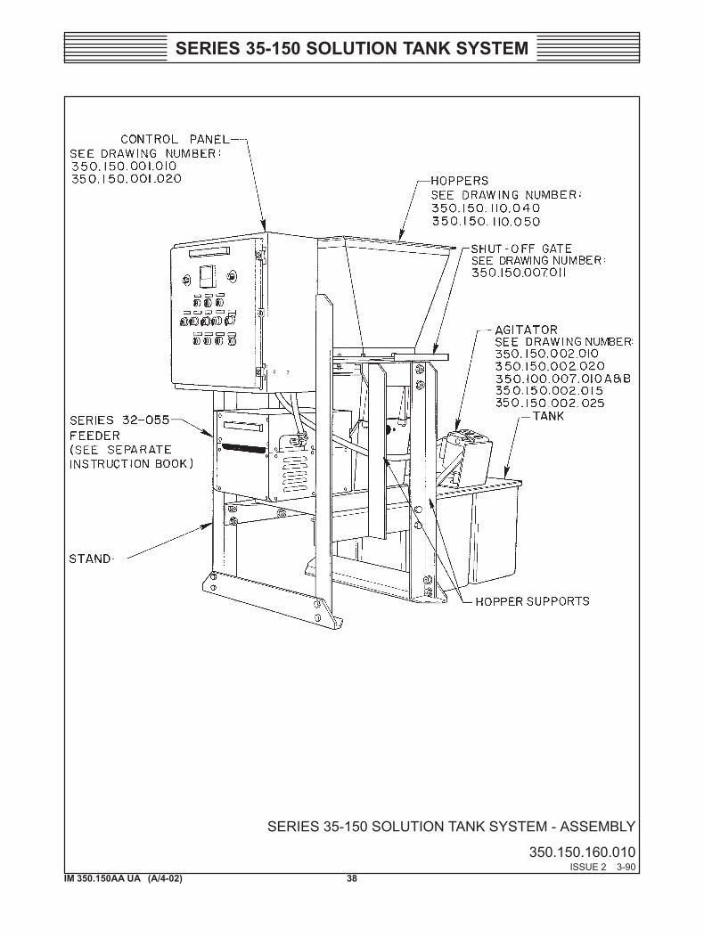
In floor-supported feeder system the solution tank is along side the feeder.This system uses only the 35-gallon solution tank. See Dwg.350.150.160.010 for typical system. In this arrangement the system isprewired except for the mixer motor wiring which must be connected inthe field. Hoppers above the feeder hopper must be field installed.
2.2 Location and Basic Installation
Select a location for the solution tank system that has sufficient space topermit access for inspection and service. Ensure that the site has suitabledrainage facilities, a source of electrical power and water supply. Providemeans of venting the cleaned air from the dust removal system as detailedin paragraph 3.5, Theory of Operation.
2.2.1 Feeder on Solution Tank
a. Mount the solution tank on a strong, rigid floor, preferably a con-crete pad as shown in Dwg. 350.150.110.010.
b. Prior to placing the tank in position, coat the tank area of the floorand the underside of the tank liberally with the plastic roof cementsupplied (U13353). This will prevent the accumulation of water un-der the tank and together with normal maintenance painting will en-sure a satisfactory service life for the tank.
2.2.2 Feeder on Stand Alongside Solution Tank (See Dwg. 350.150.110.010)
When the feeder is mounted on a stand instead of directly on the solutiontank, bolt the stand to the floor or concrete pad with 1/2-inch lag screwsor bolts.
2.2.3 Flexible Connection and Shut-Off Gate
When the feeder is mounted on the floor supported 3000-lb. capacitystand, (Dwg. 350.150.110.050) or when the overhead hoppering is sup-ported by the floor above as shown in Dwg. 350.150.110.040 the flexible
9IM 350.150AA UA (A/4-02)
SERIES 35-150 SOLUTION TANK SYSTEM
connection between the overhead hoppers and the feeder hopper must beused. The shut-off gate installed above the flexible connection will greatlysimplify servicing the feeder. By shutting the gate and detaching theflexible connection from the feeder, the complete feeder can be removedfrom under the hoppers while they remain in place with the chemicalinside. See Dwg. 350.150.007.011 for installation of flexible connectionand shut-off gate.
With feeder supported hoppering arrangements (Dwg. 350.150.110.050)a flexible connection is not used. In this case all hoppers must be removedfrom the feeder before servicing can be performed.
2.2.4 Hoppers
a. Install overhead hoppers using hardware supplied.
b. Apply joint sealant E295 to hopper joints.
WARNING: FOR OVERHEAD FLOOR SUPPORTEDHOPPERING, THE TOTAL WEIGHT OF HOPPERS, BAGLOADER OR DUST COLLECTOR AND CHEMICAL MUST NOTEXCEED THE MAXIMUM ALLOWABLE FLOOR LOADING.FOR STAND SUPPORTED HOPPERING, THE TOTAL WEIGHTOF HOPPERING BAG LOADER OR DUST COLLECTOR ANDCHEMICAL MUST NOT EXCEED 3000 LBS. FOR FEEDER SUP-PORTED HOPPERING, THE TOTAL WEIGHT OF HOPPERSAND CHEMICAL MUST NOT EXCEED 1000 LBS. INSTALLADEQUATE STABILIZING STRUCTURES WHEN HOPPERSARE FREE STANDING.
2.2.5 Vibrators
Attach vibrator(s) (electric or pneumatic) to hoppers as shown in Dwg.350.150.110.060.
2.2.6 Connections
• Water Supply and Drain
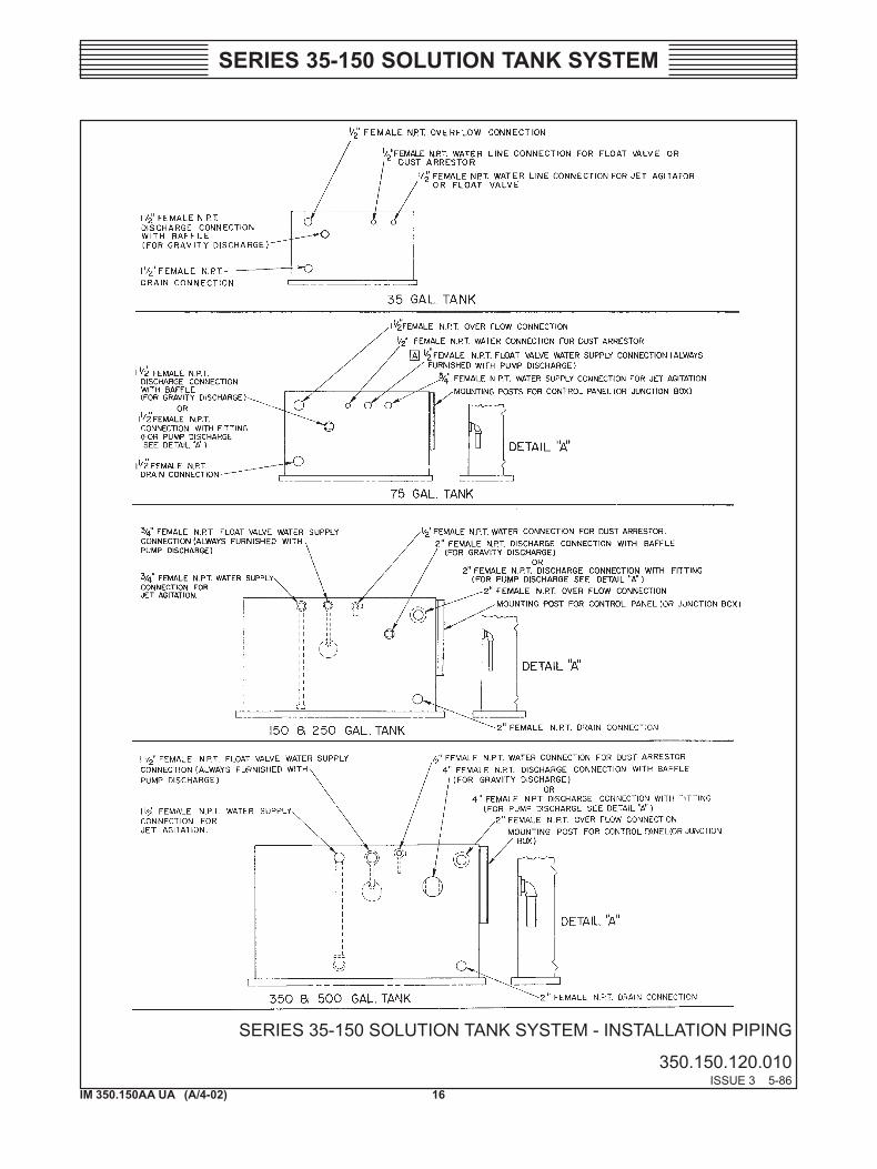
a. Connect water supply to tank fittings for jet agitator, dust arres-tor, and float valve when supplied (see Dwg. 350.150.120.010).
NOTE: Float valve ball and rod have been secured for safe shipment.Remove tie-down.
!
10IM 350.150AA UA (A/4-02)
SERIES 35-150 SOLUTION TANK SYSTEM
b. Install necessary valves in water supply lines.
c. Install suitable drain valve and piping from tank drain connec-tion.
NOTE: Connect a tee to the tank overflow fitting with one line goingto a suitable drain, the other line to vent (outside the building).
• Electrical
NOTE: Field wiring must be in accordance with the applicable USF/W&T wiring drawing and must conform to local electrical codes.When the system control panel is installed at a remote location, fieldwiring includes wiring between the control panel and the junctionbox located on the solution tank or feeder stand. Disregard the wiringinstructions in the separate feeder instruction book.
CAUTION: Read instruction book before operating, servicing orconnecting this equipment to a power source.
Electrical supply must be 115 Vac 60 Hz 1-phase or 230/460 Vac 60Hz 3-phase. If supply is not 115 Vac, the control panel must have astep-down transformer as shown in Dwg. 350.150.140.020.
a. Control Panel (see Dwgs. 350.150.140.010 and .020). Before con-necting power supply as shown in drawings, remove main fuseFU1. Check all electrical plug-in components in panel, such asrelays, SCR components and fuse FU2 to be certain they are se-curely in place. Connect main power supply to the control panel.
NOTE: If the feeder system has been supplied for operation in ahazardous area, the electrical control panel is separate from the restof the system and must be installed in a non-hazardous remote loca-tion.
b. Optional Remote Equipment (not supplied by USF/W&T). Con-nect optional remote equipment such as alarm contact (AC), flowcontacts (NFC) flow proportional contacts (FP) and mA flowsignal device.
c. Vibrators
WARNING: DO NOT USE ELECTRIC VIBRATOR IN HAZARD-OUS LOCATIONS.!
!
11IM 350.150AA UA (A/4-02)
SERIES 35-150 SOLUTION TANK SYSTEM
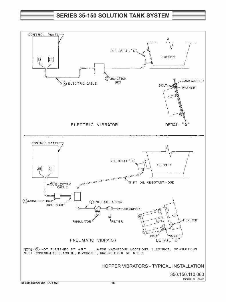
If electric vibrator has been attached to hopper as directed above,connect vibrator wires to panel terminals 23 and 24.
NOTE: Connect vibrator ground wire to terminal G in control panel.
If pneumatic vibrator is used, connect solenoid valve to terminals23 and L2.
NOTE: For hazardous locations, solenoid valves have been suppliedwhich are approved for Class II, Div. 1, Groups F and G.
d. Agitator motor
If feeder is stand-mounted, connect the free end of the agitatormotor cables (other end is attached to control panel) to agitatormotors as shown on the inside of motor terminal cover. Agitatormotor rotation must be counterclockwise when viewed from theend opposite the propeller shaft.

12IM 350.150AA UA (A/4-02)
SERIES 35-150 SOLUTION TANK SYSTEM
SERIES 35-150 SOLUTION TANK SYSTEM - TYPICAL INSTALLATION
350.150.110.010ISSUE 1 9-79
NOTE: X NOT FURNISHED BY USF/W&T. A ACCESSORY ITEM FURNISHED ONLY IF SPECIFICALLY LISTED IN QUOTA-TION.
ALL PIPING TO BE SUITABLY SUPPORTED TO AVOID STRAIN ON SOLUTION TANK CONNECTIONS.
13IM 350.150AA UA (A/4-02)
SERIES 35-150 SOLUTION TANK SYSTEM
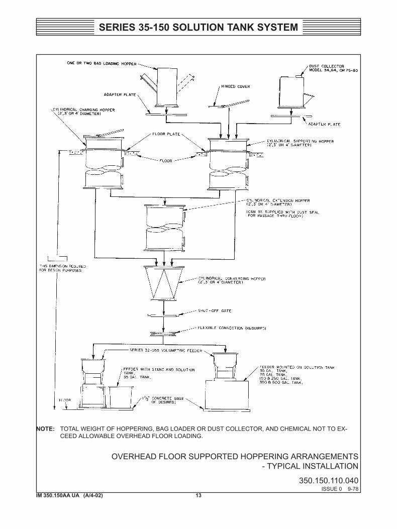
OVERHEAD FLOOR SUPPORTED HOPPERING ARRANGEMENTS - TYPICAL INSTALLATION
350.150.110.040ISSUE 0 9-78
NOTE: TOTAL WEIGHT OF HOPPERING, BAG LOADER OR DUST COLLECTOR, AND CHEMICAL NOT TO EX-CEED ALLOWABLE OVERHEAD FLOOR LOADING.
14IM 350.150AA UA (A/4-02)
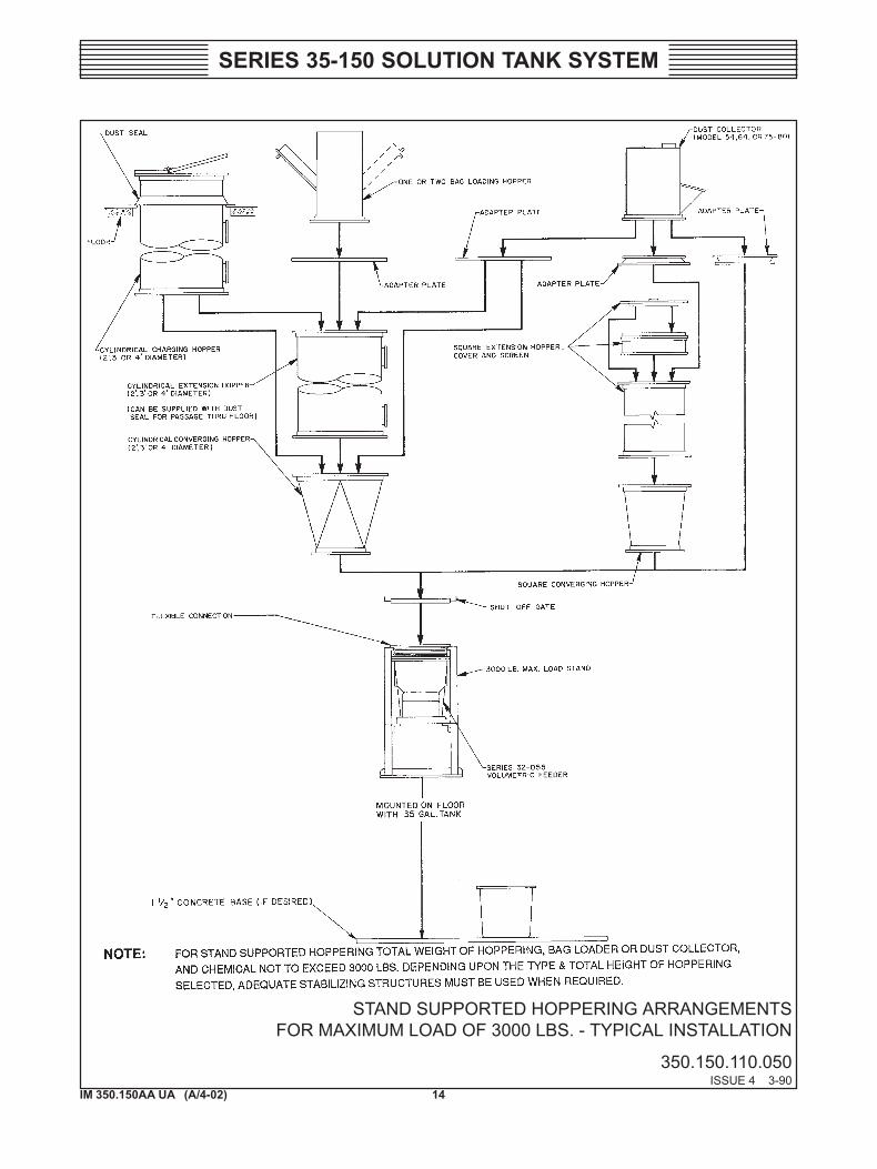
SERIES 35-150 SOLUTION TANK SYSTEM
STAND SUPPORTED HOPPERING ARRANGEMENTSFOR MAXIMUM LOAD OF 3000 LBS. - TYPICAL INSTALLATION
350.150.110.050ISSUE 4 3-90
15IM 350.150AA UA (A/4-02)
SERIES 35-150 SOLUTION TANK SYSTEM
HOPPER VIBRATORS - TYPICAL INSTALLATION
350.150.110.060ISSUE 0 9-78
16IM 350.150AA UA (A/4-02)
SERIES 35-150 SOLUTION TANK SYSTEM
SERIES 35-150 SOLUTION TANK SYSTEM - INSTALLATION PIPING
350.150.120.010ISSUE 3 5-86
17IM 350.150AA UA (A/4-02)
SERIES 35-150 SOLUTION TANK SYSTEM
SECTION 3 - OPERATION
List Of Contents
PARA./DWG. NO.
Operating Arrangements .......................................... 3.1Local Manual Start/Stop Operation ....................... 3.1.1Local Manual and Remote (Manual or Automatic)
Start/Stop Operation ........................................... 3.1.2Local Manual and Remote (Manual or Automatic)
Start/Stop with Automatic mA Feed RateControl ................................................................ 3.1.3
Preparation for Initial Starting .................................. 3.2Chemical Supply ................................................... 3.2.1Control Panel ......................................................... 3.2.2Water Supply ......................................................... 3.2.3
Operation .................................................................. 3.3Vibrator .................................................................. 3.3.1Agitator .................................................................. 3.3.2Switches ................................................................. 3.3.3
Stopping the System ................................................. 3.4Theory of Operation ................................................. 3.5Illustrations
Service - Baffle Ring ............................................. 350.150.150.010
18IM 350.150AA UA (A/4-02)
SERIES 35-150 SOLUTION TANK SYSTEM
WARNING: TO AVOID POSSIBLE SEVERE PERSONAL INJURYDO NOT OPERATE WITHOUT SHAFT GUARD IN PLACE.
3.1 Operating Arrangements
3.1.1 Local Manual Start/Stop Operation (See Dwgs. 350.150.140.010, .020)
In this arrangement one feeder switch (SS2) marked FEEDER START/STOP has two positions; RUN and STOP. Manual feed rate control isprovided by the Speed Control Potentiometer (SC1).
3.1.2 Local Manual and Remote (Manual Or Automatic) Start/Stop Operation (SeeDwg. 350.150.140.030).
One feeder switch (SS6) marked FEEDER START/STOP with three po-sitions: LOCAL, STOP and REMOTE is provided. With switch in LO-CAL position feeder will run. In REMOTE position feeder will either runor stop depending upon the position of the remote start/stop contacts (FP).Manual feed rate control (if provided) by Speed Control Potentiometer(SC1).
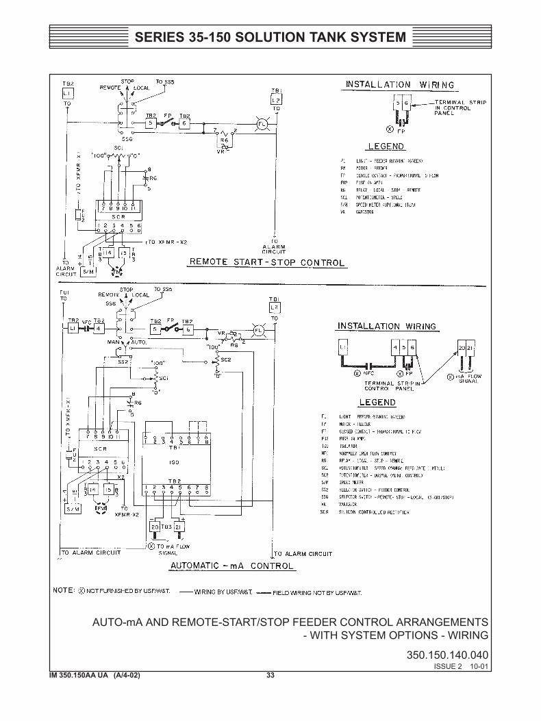
3.1.3 Local Manual and Remote (Manual or Automatic) Start/Stop With AutomaticmA Feed Rate Control (See Dwg. 350.150.140.030)
Two feeder switches are provided. FEEDER START/STOP switch (SS6)has three positions; LOCAL, STOP and REMOTE and FEEDER CON-TROL switch (SS2) has two positions, MAN and AUTO.
With SS6 in either LOCAL or REMOTE and SS2 in MANUAL, feed ratecontrol is manually set on SC1 and operation is the same as in arrangement1.2 above. With SS2 in AUTO position, the feed rate is automaticallyvaried by a signal from the customer-provided 1-5, 4-20 or 10-50 mAdevice.
The dosage control potentiometer (SC2) is manually set to the desiredlevel. The manual feed rate control potentiometer (SC1) is disabled in thisAUTO mode.
3.2 Preparation for Initial Starting
NOTE: Consult separate instruction book for Series 32-055 feeder.
!
19IM 350.150AA UA (A/4-02)
SERIES 35-150 SOLUTION TANK SYSTEM
3.2.1 Chemical Supply
Fill hoppers with chemical. When filling the hopper for the first time, pourmaterial in slowly to prevent it passing out the feed spout.
3.2.2 Control Panel (See Dwg. 350.150.001.010)
WARNING: TO AVOID POSSIBLE SEVERE PERSONAL INJURYFROM ELECTRICAL SHOCK, THE MAIN POWER SWITCH(NOT SUPPLIED BY USF/W&T) MUST BE OFF.
a. Reinstall fuse FU1.
b. Close and secure panel door.
c. Set hopper vibrator and agitator switch to OFF position.
d. Set FEEDER START/STOP switch to STOP.
e. Set FEEDER CONTROL switch to MAN.
f. Set manual speed control potentiometer (SC1) and dosage controlpotentiometer (SC2) to zero.
g. Close main power switch.
3.2.3 Water Supply
a. Turn on supply water to all solution tank connections (see Dwg.350.100.190.010) to determine the maximum inlet flow with avail-able water pressure.
b. Remove tank access covers. Fill tank to normal operating level.
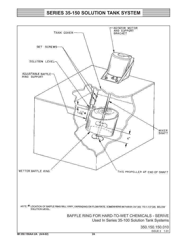
c. If system is being used for feeding hard-to-wet materials such ascarbon, adjust wetter baffle as follows (see Dwg. 350.150.150.010).
(1) Turn agitator switch to ON position and observe agitator mixingaction. A definite, deep vortex should occur within the bafflering. Loosen set screw and adjust depth of ring to obtain maxi-mum vortex. Tighten the two set screws.
(2) Turn agitator switch to OFF.
(3) Replace access cover(s).
!
20IM 350.150AA UA (A/4-02)
SERIES 35-150 SOLUTION TANK SYSTEM
NOTE: Feeder is now ready for operation.
3.3 Operation
3.3.1 Vibrator
If optional vibrator is part of system, turn vibrator switch to ON.
NOTE: The vibrator switch is interlocked so that it cannot operateunless the feeder is running. The vibrator timer has a 30 second cycleand may be adjusted for a maximum on-time of 13 seconds per cycle.
3.3.2 Agitator
With tank water at operating level, turn agitator switch(es) ON.
21IM 350.150AA UA (A/4-02)
SERIES 35-150 SOLUTION TANK SYSTEM
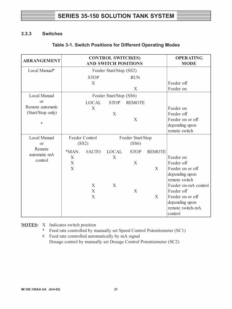
3.3.3 Switches
Table 3-1. Switch Positions for Different Operating Modes
TNEMEGNARRA )SE(HCTIWSLORTNOCSNOITISOPHCTIWSDNA
GNITAREPOEDOM
*launaMlacoL )2SS(potS/tratSredeeFPOTS
XNUR
XfforedeeF
noredeeFlaunaMlacoL
rocitamotuaetomeR)ylnopotS/tratS(
*
)6SS(potS/tratSredeeFLACOL
XPOTS
X
ETOMER
X
noredeeFfforedeeF
fforonoredeeFnopugnidneped
hctiwsetomerlaunaMlacoL
roetomeR
Amcitamotualortnoc
lortnoCredeeF)2SS(
potS/tratSredeeF)6SS(
.NAM*XXX
OTUA#
XXX
LACOLX
X
POTS
X
X
ETOMER
X
X
noredeeFfforedeeF
fforonoredeeFnopugnidneped
hctiwsetomerlortnocAm-noredeeF
fforedeeFfforonoredeeF
nopugnidnepedAm-hctiwsetomer
lortnoc
NOTES: X Indicates switch position* Feed rate controlled by manually set Speed Control Potentiometer (SC1)# Feed rate controlled automatically by mA signal
Dosage control by manually set Dosage Control Potentiometer (SC2)
22IM 350.150AA UA (A/4-02)
SERIES 35-150 SOLUTION TANK SYSTEM
a. Set feeder switch(es) as indicated in the table for local-run mode.Use manual speed control potentiometer SC1 to calibrate the feederas described in feeder instruction book.
b. Use the calibrated curve to determine the proper speed setting of thefeeder motor for the desired chemical feed rate in pounds per minute.
c. In the automatic mode (1.3) the manual dosage control potentiom-eter (SC2) setting in addition to the mA input signal determines thefeed rate (or speed).
NOTE: Refer to the table for various switch positions for differentoperating modes.
d. ALARM ACKNOWLEDGEMENT button (when supplied) is a pushbutton switch which silences the alarm bell and/or deactivates theauxiliary alarm light (A-3) and remote alarms.
3.4 Stopping the System
a. Turn feeder switch to STOP.
b. Turn vibrator switch to OFF.
c. Turn off water supplies to the tank to prevent dilution of the solution.
d. Leave agitator(s) running to keep the solution thoroughly mixed.
NOTE: Keep the tank covers and feeder covers closed except whennecessary to open for observation purposes. Downspout cover is readilyremovable for observation of chemical flow.
3.5 Theory of Operation
Dry chemical flows by gravity from the hoppers to the feed screw via thefeeder hopper. Positive action oscillating diaphragm agitators in the hop-per prevent caking or arching. With certain free-flowing materials, agita-tors are not required. The single-ended-delivery feed screw meters chemicalinto the solution tank through a stainless steel (or TFE for polyelectrolyte)discharge spout. For both tank-mounted and stand-mounted feeders chemi-cal is delivered into the tank through a downspout. In the tank, thoroughmixing is accomplished by a submerged triple jet mixer and one or twomechanical agitators (motor driven three- or four-inch propellers) de-pending on tank size.
23IM 350.150AA UA (A/4-02)
SERIES 35-150 SOLUTION TANK SYSTEM
The dust and vapor removal system consists of water spraying into athree-inch diameter PVC pipe creating a flow of air through the pipe.Holes along the bottom of the pipe allow the water to drop back into thetank while the cleansed air flows through the pipe to a fitting in the wallof the tank. This fitting also serves as the overflow connection. With a teeconnected to this fitting one end is vented to atmosphere discharging theclean air while the other end is connected to a suitable drain.
The discharge from the tank is normally by gravity through a two-inchpipe connector protected by a baffle. The baffle prevents material onwater surface from leaving the tank. For the optional pump suction ar-rangement the baffle is replaced by a pipe that extends well below thesolution level. A float valve maintains the constant solution level.
The feeder, agitators and hopper vibrators are stopped, started, controlledand monitored from the control panel.
24IM 350.150AA UA (A/4-02)
SERIES 35-150 SOLUTION TANK SYSTEM
BAFFLE RING FOR HARD-TO-WET CHEMICALS - SERIVEUsed In Series 35-100 Solution Tank Systems
350.150.150.010ISSUE 2 1-91
25IM 350.150AA UA (A/4-02)
SERIES 35-150 SOLUTION TANK SYSTEM
SECTION 4 - SERVICE
List Of Contents
PARA./DWG. NO.
General ..................................................................... 4.1Cleaning ................................................................. 4.1.1Inspection .............................................................. 4.1.2Troubleshooting ..................................................... 4.1.3
Warning Summary Page ........................................... 1 PageIllustrations
Wiring .................................................................... 350.150.140.010Wiring .................................................................... 350.150.140.020Wiring .................................................................... 350.150.140.030Wiring .................................................................... 350.150.140.040Wiring .................................................................... 350.150.140.050Wiring .................................................................... 350.150.140.060
26IM 350.150AA UA (A/4-02)
SERIES 35-150 SOLUTION TANK SYSTEM
4.1 General
WARNING: TO AVOID POSSIBLE SEVERE PERSONAL INJURYFROM ELECTRICAL SHOCK, TURN OFF POWER BEFORESERVICING.
Maintenance of the Series 35-150 Solution Tank System consists prima-rily of servicing the Feeder, Series 32-055. For maintenance of this com-ponent refer to the Feeder Instruction Book.
Refer to paragraph 2.2.4, Hoppers, for removal of feeder with overheadhoppers and chemical load in place.
4.1.1 Cleaning
• Normally, the rest of this system only requires occasional cleaning.Frequency of cleaning depends upon the material being fed and theenvironment.
• Occasionally (every two to three days), remove the downspout capto be certain the chemical is not caking and sticking to the inside ofthe downspout. Remove accumulated chemical if required.
• Periodically (every week), remove solution tank access covers andinspect float valve ball, dust arrestor and inside of tank. Clean asrequired.
4.1.2 Inspection
Periodically (every two to three months), inspect the agitator motor shaftseal (8, Dwg. 350.100.007.011) or (19, Dwg. 350.150.002.020) for wear.
WARNING: TO AVOID POSSIBLE SEVERE PERSONAL INJURYFROM CONTACT WITH MOVING PARTS, DO NOT OPERATEWITHOUT SHAFT GUARD IN PLACE.
4.1.3 Troubleshooting
The following troubleshooting guide has been provided to assist in reduc-ing equipment down-time.
!
!

27IM 350.150AA UA (A/4-02)
SERIES 35-150 SOLUTION TANK SYSTEMTa
ble
4-1.
Tro
uble
shoo
ting
MOTP
MYSES
NOPSE
RT
NEMPI
UQE
ESU
AC
ELB
AB
ORP
YDE
MER
LLIW
REDEEF
NIETA
REPO
TO
NET
OME
R,LA
COL
OTU
AR
O.SE
DO
M
orezsahrete
mdeepsredeeF
deeftonlliwredeef
dnatuptuo.laci
mehc.n
wolb)2UF(
esuF
.noitcennocesoolro
gniriw
ytluaF
.hctiws
potS/tratSredeefytluaF
lortnocdeepslauna
MFF
Oni)1
CS(retemoitnetop.noitisop
.6-Ryaler
ytluaF*
retemoitnetoplortnoc
egasoD*
.noitisopFF
Oni)2
CS(
)CF
N(stcatnoc
etomer
ytluaF*.)PF(ro/dna
nin
wohssa
snoitisophcti
wskceh
C.4
noitceSni
elbat
.esufecalpeR
.gniriwtcennocerro
ecalpeR
.ecalperroriapeR
.gnittesrehgihot
bonkteS
.yalerecalpeR
.gnittesrehgihot
bonkteS
.tnempiuqe
ytluafecalperroriapeR
LLIW
REDEEF
ETAREP
OT
ON
tubtuptuosahrete
mdeepsredeeF
.lacimehc
deeftonlliwredeef
.ytpmereppo
H
.eruliaflacinahceM
.ylppushsinelpeR
.koobnoitcurtsniredeef
eeS.sedo
motu
Adna
potS/tratSeto
mernI
*
28IM 350.150AA UA (A/4-02)
SERIES 35-150 SOLUTION TANK SYSTEMTa
ble
4-1.
Tro
uble
shoo
ting
(Con
t'd)
MO
TPM
YSES
NOPS
ER
TN
EMPI
UQ
EES
UA
CE
LB
AB
ORP
YD
EM
ER
LLI
WR
OT
AR
BIV
ET
AR
EPO
TO
NR
OCI
RT
CE
LE(
.)CI
TA
MU
ENP
hctiws
rotarbivhti
wesnopser
oN
.N
O.P
OT
Sni
hctiws
potS/trat
Sredee
F
.)5S
S(hcti
wsrotarbiv
ytluaF
ninoitcennoc
esoolro
gniriw
ytluaF
.lenaplortnoc
.evitareponiroto
mre
mitrotarbi
V
.evitareponistcatnoc
rotarbiV
.noitisopN
UR
othcti
wsevo
M
.ecalperro
riapeR
.gniriwtcennocer
roecalpe
R
.ecalperro
riapeR
.ecalperro
riapeR
CIR
TC
EL
E.YL
NO
RO
TA
RBI
Vdna
rotarbivnee
wtebelbac
ytluaF
.lenaplortnoc
.rellortnocrotarbiv
ytluaF
.ecalpeR
.ecalperro
riapeR
CIT
AM
UE
NP.YL
NO
RO
TA
RBI
V.erusserp
wolro
ylppusria
oN
.evlavdionelos
ytluaF
.isp001.ni
mylppu
S
.ecalperro
riapeR
LLI
WR
OT
ATIG
A.
ET
AR
EPO
TO
N.noitcennoc
esoolro
ytluaF
rotom
citengam,hcti
wsytlua
F.retrats
.gniriwtcennocer
roecalpe
R
.tnempiuqe
ytluafecalper
roriape
R
29IM 350.150AA UA (A/4-02)
SERIES 35-150 SOLUTION TANK SYSTEM
WARNING LABELS AND TAGS
The following warning labels and tags are attached to the equipment.--------------------------------------------------------------------------------------L2077: TO AVOID POSSIBLE PERSONAL INJURY FROM
CONTACT WITH MOVING PARTS OPERATE ONLYWITH GUARD IN PLACE.
--------------------------------------------------------------------------------------L2022: TO AVOID POSSIBLE SEVERE PERSONAL INJURY
FROM ELECTRICAL SHOCK, TURN POWER OFF BE-FORE SERVICING.
--------------------------------------------------------------------------------------
30IM 350.150AA UA (A/4-02)
SERIES 35-150 SOLUTION TANK SYSTEM
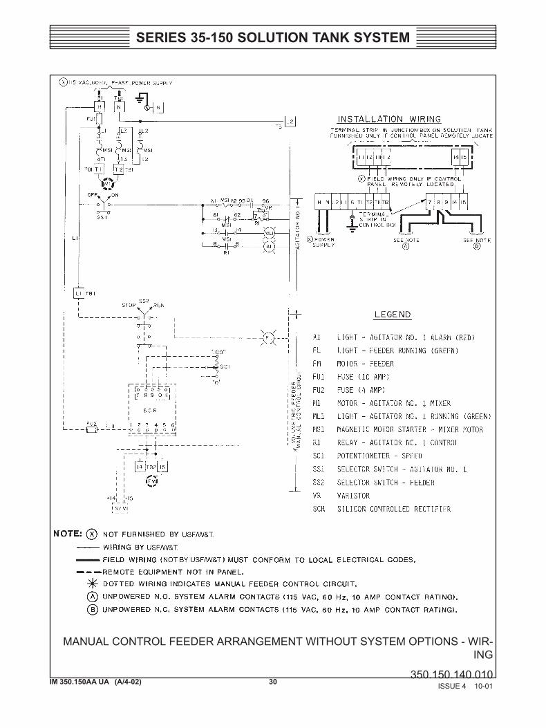
MANUAL CONTROL FEEDER ARRANGEMENT WITHOUT SYSTEM OPTIONS - WIR-ING
350.150.140.010ISSUE 4 10-01
31IM 350.150AA UA (A/4-02)
SERIES 35-150 SOLUTION TANK SYSTEM
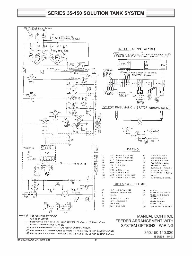
MANUAL CONTROLFEEDER ARRANGEMENT WITH
SYSTEM OPTIONS - WIRING
350.150.140.020ISSUE 4 10-01
32IM 350.150AA UA (A/4-02)
SERIES 35-150 SOLUTION TANK SYSTEM
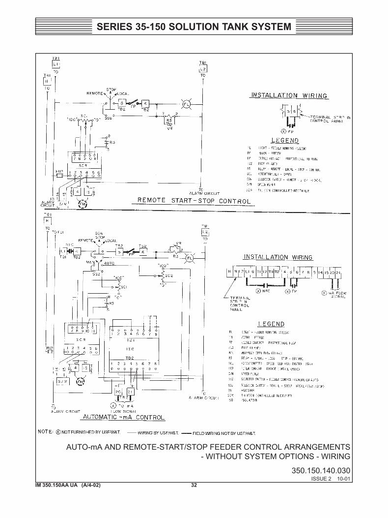
AUTO-mA AND REMOTE-START/STOP FEEDER CONTROL ARRANGEMENTS - WITHOUT SYSTEM OPTIONS - WIRING
350.150.140.030ISSUE 2 10-01
33IM 350.150AA UA (A/4-02)
SERIES 35-150 SOLUTION TANK SYSTEM
AUTO-mA AND REMOTE-START/STOP FEEDER CONTROL ARRANGEMENTS - WITH SYSTEM OPTIONS - WIRING
350.150.140.040ISSUE 2 10-01
34IM 350.150AA UA (A/4-02)
SERIES 35-150 SOLUTION TANK SYSTEM
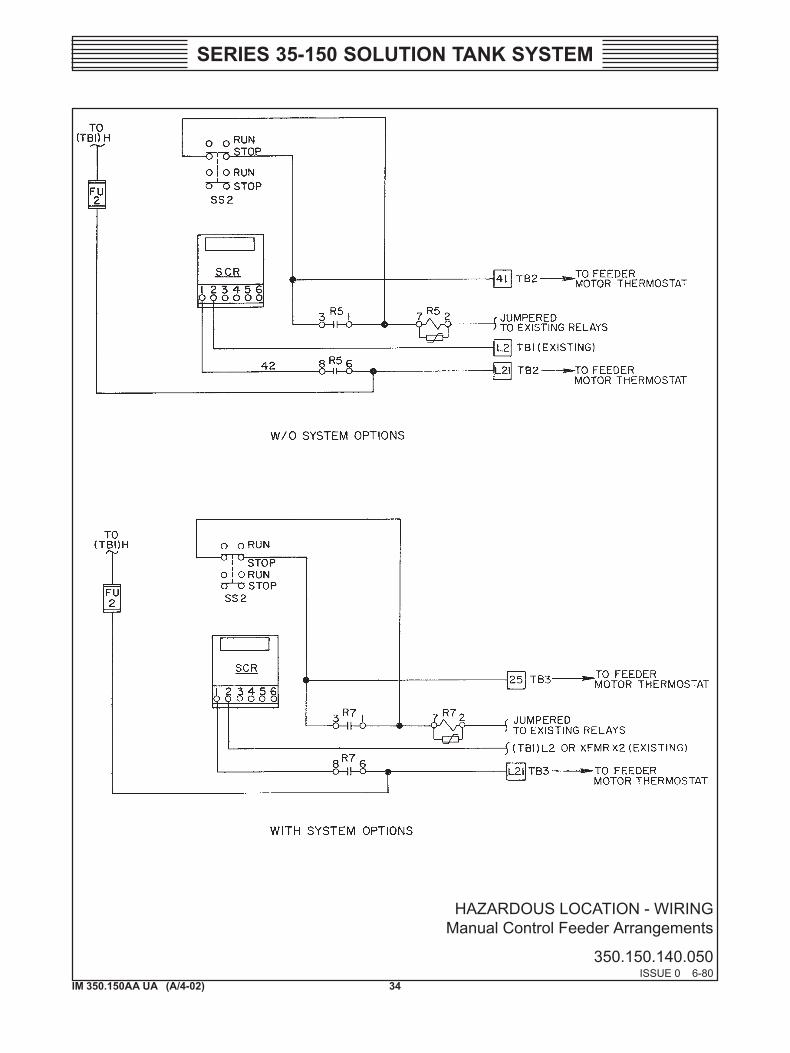
HAZARDOUS LOCATION - WIRINGManual Control Feeder Arrangements
350.150.140.050ISSUE 0 6-80
35IM 350.150AA UA (A/4-02)
SERIES 35-150 SOLUTION TANK SYSTEM
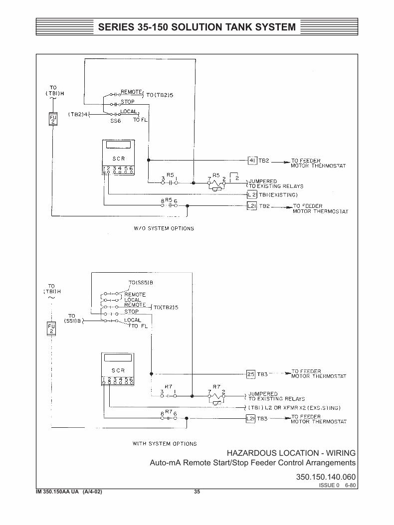
HAZARDOUS LOCATION - WIRINGAuto-mA Remote Start/Stop Feeder Control Arrangements
350.150.140.060ISSUE 0 6-80

36IM 350.150AA UA (A/4-02)
SERIES 35-150 SOLUTION TANK SYSTEM
37IM 350.150AA UA (A/4-02)
SERIES 35-150 SOLUTION TANK SYSTEM
SECTION 5 - ILLUSTRATIONS
List Of Contents
DWG. NO.
Assembly - Solution Tank System ..................... 350.150.160.010Parts
U25531 Control Panel ..................................... 350.150.001.010A-CU24527 Control Panel ..................................... 350.150.001.020A-CControl Panel Options ..................................... 350.150.001.030A-CG1336 Agitator (35-gallon) ............................. 350.150.002.010G1229 Agitator (35-gallon) Hard-To-Wet
Material ......................................................... 350.150.002.015G818 Agitator .................................................. 350.150.002.020G1312 Agitator (75-gallon) Hard-To-Wet
Material ......................................................... 350.150.002.025G520 Agitator .................................................. 350.100.007.010A&BU24444 Float Valve ........................................ 350.150.003.010U24445 Float Valve ........................................ 350.150.003.020U24232 Plastic Float Valve ............................. 350.150.003.030U24514 Float Valve ........................................ 350.150.003.04030 GPM Float Valve Unit ................................ 311.000.30.034Float Valve ...................................................... 350.150.003.050U22274 Dust Arrestor ..................................... 350.150.004.010U17327 Dust Arrestor ..................................... 350.150.004.020UXA17508 Dust Arrestor Water Line............. 311.000.30.093U19676 Solution Tank and Inlet Water Line .. 350.150.005.010A&BU24511 Inlet Water Line ................................. 350.150.005.020U23278 Inlet Water Line ................................. 350.100.008.010G530 Inlet Water Line ..................................... 350.100.009.010A&BDischarge Pipes and Baffle-75 Gal ................. 350.150.006.020Discharge Pipes and Baffle-150/250 Gal ........ 350.150.006.030Discharge Pipes and Baffle-350/500 Gal ........ 350.150.006.040U26880 Shut-Off Gate..................................... 350.150.007.011
38IM 350.150AA UA (A/4-02)
SERIES 35-150 SOLUTION TANK SYSTEM
SERIES 35-150 SOLUTION TANK SYSTEM - ASSEMBLY
350.150.160.010ISSUE 2 3-90
39IM 350.150AA UA (A/4-02)
SERIES 35-150 SOLUTION TANK SYSTEM
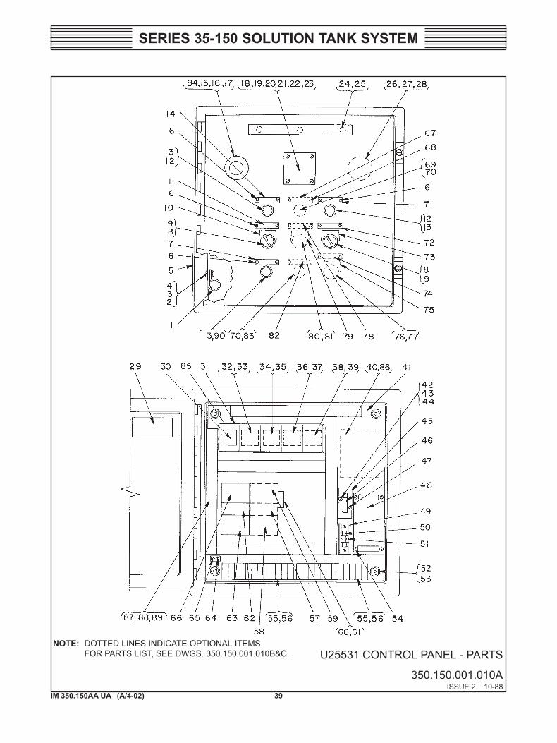
U25531 CONTROL PANEL - PARTS
350.150.001.010AISSUE 2 10-88
NOTE: DOTTED LINES INDICATE OPTIONAL ITEMS.FOR PARTS LIST, SEE DWGS. 350.150.001.010B&C.
40IM 350.150AA UA (A/4-02)
SERIES 35-150 SOLUTION TANK SYSTEM
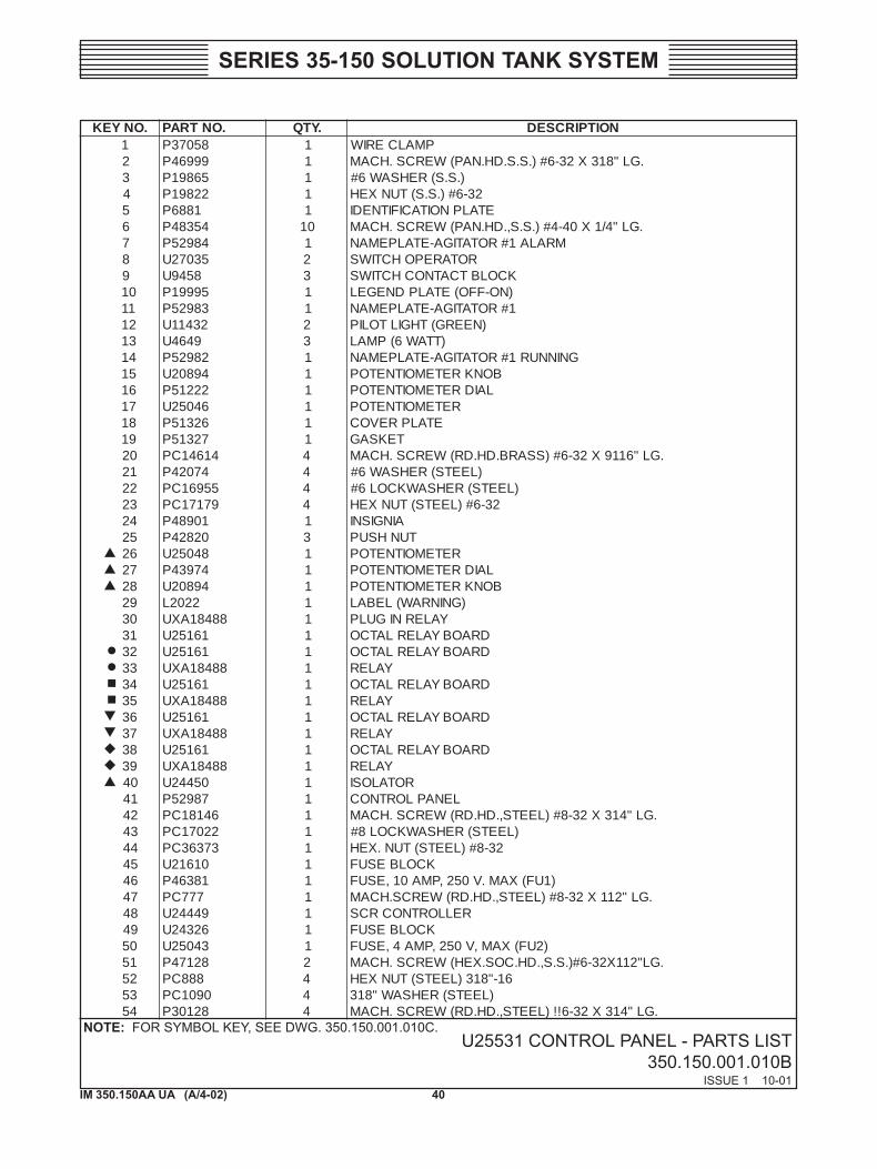
U25531 CONTROL PANEL - PARTS LIST350.150.001.010B
ISSUE 1 10-01
.ONYEK .ONTRAP .YTQ NOITPIRCSED1 85073P 1 PMALCERIW2 99964P 1 .GL"813X23-6#).S.S.DH.NAP(WERCS.HCAM3 56891P 1 ).S.S(REHSAW6#4 22891P 1 23-6#).S.S(TUNXEH5 1886P 1 ETALPNOITACIFITNEDI6 45384P 01 .GL"4/1X04-4#).S.S,.DH.NAP(WERCS.HCAM7 48925P 1 MRALA1#ROTATIGA-ETALPEMAN8 53072U 2 ROTAREPOHCTIWS9 8549U 3 KCOLBTCATNOCHCTIWS01 59991P 1 )NO-FFO(ETALPDNEGEL11 38925P 1 1#ROTATIGA-ETALPEMAN21 23411U 2 )NEERG(THGILTOLIP31 9464U 3 )TTAW6(PMAL41 28925P 1 GNINNUR1#ROTATIGA-ETALPEMAN51 49802U 1 BONKRETEMOITNETOP61 22215P 1 LAIDRETEMOITNETOP71 64052U 1 RETEMOITNETOP81 62315P 1 ETALPREVOC91 72315P 1 TEKSAG02 41641CP 4 .GL"6119X23-6#)SSARB.DH.DR(WERCS.HCAM12 47024P 4 )LEETS(REHSAW6#22 55961CP 4 )LEETS(REHSAWKCOL6#32 97171CP 4 23-6#)LEETS(TUNXEH42 10984P 1 AINGISNI52 02824P 3 TUNHSUP62 84052U 1 RETEMOITNETOP72 47934P 1 LAIDRETEMOITNETOP82 49802U 1 BONKRETEMOITNETOP92 2202L 1 )GNINRAW(LEBAL03 88481AXU 1 YALERNIGULP13 16152U 1 DRAOBYALERLATCO23 16152U 1 DRAOBYALERLATCO33 88481AXU 1 YALER43 16152U 1 DRAOBYALERLATCO53 88481AXU 1 YALER63 16152U 1 DRAOBYALERLATCO73 88481AXU 1 YALER83 16152U 1 DRAOBYALERLATCO93 88481AXU 1 YALER04 05442U 1 ROTALOSI14 78925P 1 LENAPLORTNOC24 64181CP 1 .GL"413X23-8#)LEETS,.DH.DR(WERCS.HCAM34 22071CP 1 )LEETS(REHSAWKCOL8#44 37363CP 1 23-8#)LEETS(TUN.XEH54 01612U 1 KCOLBESUF64 18364P 1 )1UF(XAM.V052,PMA01,ESUF74 777CP 1 .GL"211X23-8#)LEETS,.DH.DR(WERCS.HCAM84 94442U 1 RELLORTNOCRCS94 62342U 1 KCOLBESUF05 34052U 1 )2UF(XAM,V052,PMA4,ESUF15 82174P 2 .GL"211X23-6#).S.S,.DH.COS.XEH(WERCS.HCAM25 888CP 4 61-"813)LEETS(TUNXEH35 0901CP 4 )LEETS(REHSAW"81345 82103P 4 .GL"413X23-6!!)LEETS,.DH.DR(WERCS.HCAM
NOTE: FOR SYMBOL KEY, SEE DWG. 350.150.001.010C.
41IM 350.150AA UA (A/4-02)
SERIES 35-150 SOLUTION TANK SYSTEM
U25531 CONTROL PANEL- PARTS LIST
350.150.001.010CISSUE 3 10-01
NOTE: NOT PART OF U 25531.PART OF G 842.PART OF G 845.PART OF G 883.PART OF G 514.PART OF G 1296.
.ONYEK .ONTRAP .YTQ NOITPIRCSED55 62612U 2 ).TP21(PIRTSLANIMRET65 9617CP 4 .GL"1x23-8#)SSARB,.DH.DR(WERCS.HCAM75 42882U 1 TCATNOCYRAILIXUA85 ----- 1 )WOLEBTRAHCEES(YALERDAOLREVO95 25972U 1 ROTCATNOCROTOM06 16182U "5 LIARGNITNUOM16 137P 2 .GL"8/3x23-01#).LTS,.DH.DR(WERCS.HCAM26 42882U 1 TCATNOCYRAILIXUA36 ----- 1 )WOLEBTRAHCEES(YALERDAOLREVO46 05405P 1 GULDNUORG56 9852CP 1 .GL"8/3x02-"4/1).LTS,.DH.DR(WERCS.HCAM66 25972U 1 ROTCATNOCROTOM76 04035P 1 GNINNUR2#ROTATIGA-ETALPEMAN86 45384P 6 .GL"4/1x04-4#)SS,.DH.NAP(WERCS.HCAM96 23411U 1 )NEERG(THGILTOLIP07 9464U 2 TTAW6,PMAL17 58925P 1 GNINNURREDEEF-ETALPEMAN27 68925P 1 POTSTRATSREDEEF-ETALPEMAN37 95264P 1 NURPOTS-ETALPDNEGEL47 88925P 1 LORTNOCREDEEF-ETALPEMAN57 99415P 1 NUR-POTS-LACOL-ETALPDNEGEL67 8549U 1 KCOLBTCATNOC
RO82552U 1 KCOLBTCATNOC
DNA92552U 1 KCOLBTCATNOC
77 63072U 1 ROTAREPOHCTIWSRO
03552U 1 ROTAREPOHCTIWS87 83035P 1 2#ROTATIGA-ETALPEMAN97 59991P 1 NO-FFO-ETALPDNEGEL08 8549U 1 KCOLBTCATNOC18 53072U 1 ROTAREPOHCTIWS28 93035P 1 MRALA2#ROTATIGA-ETALPEMAN38 13411U 1 DER-THGILTOLIP48 57325P 1 ROTALUSNI58 80422U "8/1-01 KCARTYALER68 82103P 4 .GL"4/3x23-6#).LTS,.DH.DR(WERCS.HCAM78 70823R '5 TCUDGNIRIW88 80823R '5 REVOCTCUD98 54475P 81 TEVIR09 13411U 1 DER-THGILTOLIP
SYALERDAOLREVO.ONTRAP TNERRUCDAOLLLUF35972BXU SPMA6.0-4.035972CXU SPMA0.1-6.035972DXU SPMA2.1-8.035972EXU SPMA6.1-0.135972FXU SPMA3.2-5.135972GXU SPMA0.3-0.235972HXU SPMA2.4-8.235972JXU SPMA0.6-0.435972KXU SPMA0.8-5.535972LXU SPMA0.01-0.635972MXU SPMA0.61-0.01
WHEN ORDERING MATERIAL ALWAYS SPECIFY MODEL AND SERIAL NUMBER OF APPARATUS
42IM 350.150AA UA (A/4-02)
SERIES 35-150 SOLUTION TANK SYSTEM
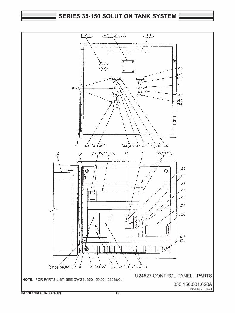
U24527 CONTROL PANEL - PARTS
350.150.001.020AISSUE 2 6-94
NOTE: FOR PARTS LIST, SEE DWGS. 350.150.001.020B&C.
43IM 350.150AA UA (A/4-02)
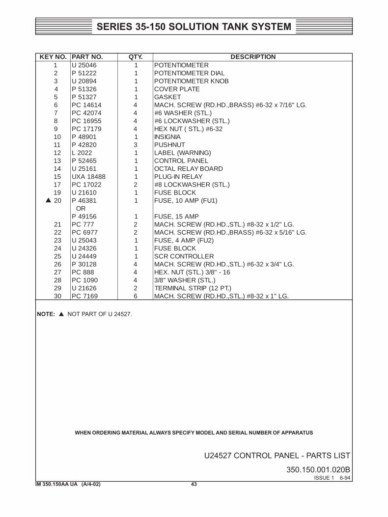
SERIES 35-150 SOLUTION TANK SYSTEM
U24527 CONTROL PANEL - PARTS LIST
350.150.001.020BISSUE 1 6-94
.ONYEK .ONTRAP .YTQ NOITPIRCSED1 64052U 1 RETEMOITNETOP2 22215P 1 LAIDRETEMOITNETOP3 49802U 1 BONKRETEMOITNETOP4 62315P 1 ETALPREVOC5 72315P 1 TEKSAG6 41641CP 4 .GL"61/7x23-6#)SSARB,.DH.DR(WERCS.HCAM7 47024CP 4 ).LTS(REHSAW6#8 55961CP 4 ).LTS(REHSAWKCOL6#9 97171CP 4 23-6#).LTS(TUNXEH01 10984P 1 AINGISNI11 02824P 3 TUNHSUP21 2202L 1 )GNINRAW(LEBAL31 56425P 1 LENAPLORTNOC41 16152U 1 DRAOBYALERLATCO51 88481AXU 1 YALERNI-GULP71 22071CP 2 ).LTS(REHSAWKCOL8#91 01612U 1 KCOLBESUF02 18364P 1 )1UF(PMA01,ESUF
RO65194P 1 PMA51,ESUF
12 777CP 2 .GL"2/1x23-8#).LTS,.DH.DR(WERCS.HCAM22 7796CP 2 .GL"61/5x23-6#)SSARB,.DH.DR(WERCS.HCAM32 34052U 1 )2UF(PMA4,ESUF42 62342U 1 KCOLBESUF52 94442U 1 RELLORTNOCRCS62 82103P 4 .GL"4/3x23-6#).LTS,.DH.DR(WERCS.HCAM72 888CP 4 61-"8/3).LTS(TUN.XEH82 0901CP 4 ).LTS(REHSAW"8/392 62612U 2 ).TP21(PIRTSLANIMRET03 9617CP 6 .GL"1x23-8#).LTS,.DH.DR(WERCS.HCAM
WHEN ORDERING MATERIAL ALWAYS SPECIFY MODEL AND SERIAL NUMBER OF APPARATUS
NOTE: NOT PART OF U 24527.
44IM 350.150AA UA (A/4-02)
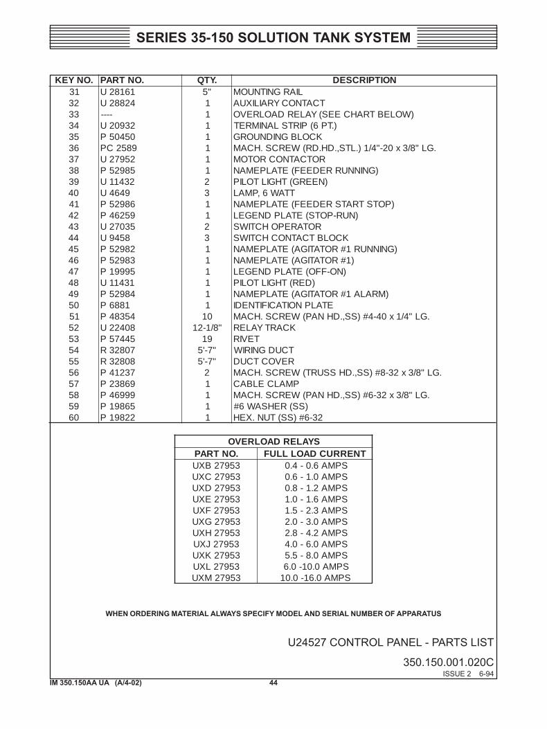
SERIES 35-150 SOLUTION TANK SYSTEM
U24527 CONTROL PANEL - PARTS LIST
350.150.001.020CISSUE 2 6-94
.ONYEK .ONTRAP .YTQ NOITPIRCSED13 16182U "5 LIARGNITNUOM23 42882U 1 TCATNOCYRAILIXUA33 ---- 1 )WOLEBTRAHCEES(YALERDAOLREVO43 23902U 1 ).TP6(PIRTSLANIMRET53 05405P 1 KCOLBGNIDNUORG63 9852CP 1 .GL"8/3x02-"4/1).LTS,.DH.DR(WERCS.HCAM73 25972U 1 ROTCATNOCROTOM83 58925P 1 )GNINNURREDEEF(ETALPEMAN93 23411U 2 )NEERG(THGILTOLIP04 9464U 3 TTAW6,PMAL14 68925P 1 )POTSTRATSREDEEF(ETALPEMAN24 95264P 1 )NUR-POTS(ETALPDNEGEL34 53072U 2 ROTAREPOHCTIWS44 8549U 3 KCOLBTCATNOCHCTIWS54 28925P 1 )GNINNUR1#ROTATIGA(ETALPEMAN64 38925P 1 )1#ROTATIGA(ETALPEMAN74 59991P 1 )NO-FFO(ETALPDNEGEL84 13411U 1 )DER(THGILTOLIP94 48925P 1 )MRALA1#ROTATIGA(ETALPEMAN05 1886P 1 ETALPNOITACIFITNEDI15 45384P 01 .GL"4/1x04-4#)SS,.DHNAP(WERCS.HCAM25 80422U "8/1-21 KCARTYALER35 54475P 91 TEVIR45 70823R "7-'5 TCUDGNIRIW55 80823R "7-'5 REVOCTCUD65 73214P 2 .GL"8/3x23-8#)SS,.DHSSURT(WERCS.HCAM75 96832P 1 PMALCELBAC85 99964P 1 .GL"8/3x23-6#)SS,.DHNAP(WERCS.HCAM95 56891P 1 )SS(REHSAW6#06 22891P 1 23-6#)SS(TUN.XEH
SYALERDAOLREVO.ONTRAP TNERRUCDAOLLLUF35972BXU SPMA6.0-4.035972CXU SPMA0.1-6.035972DXU SPMA2.1-8.035972EXU SPMA6.1-0.135972FXU SPMA3.2-5.135972GXU SPMA0.3-0.235972HXU SPMA2.4-8.235972JXU SPMA0.6-0.435972KXU SPMA0.8-5.535972LXU SPMA0.01-0.635972MXU SPMA0.61-0.01
WHEN ORDERING MATERIAL ALWAYS SPECIFY MODEL AND SERIAL NUMBER OF APPARATUS
45IM 350.150AA UA (A/4-02)
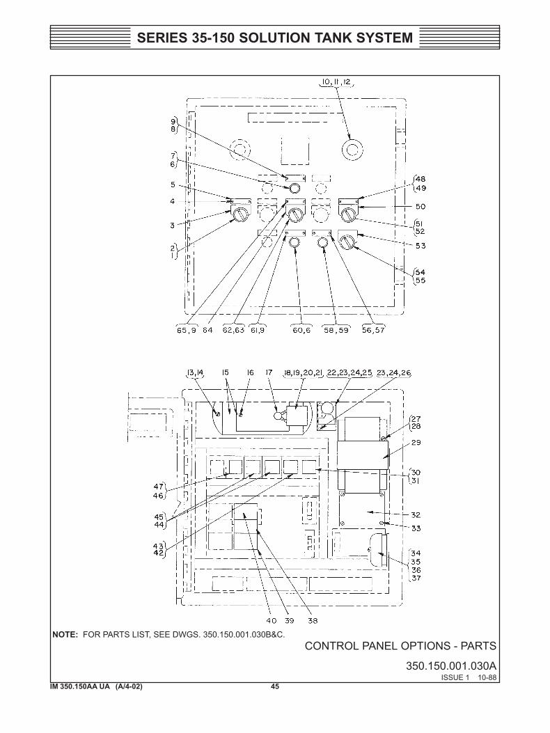
SERIES 35-150 SOLUTION TANK SYSTEM
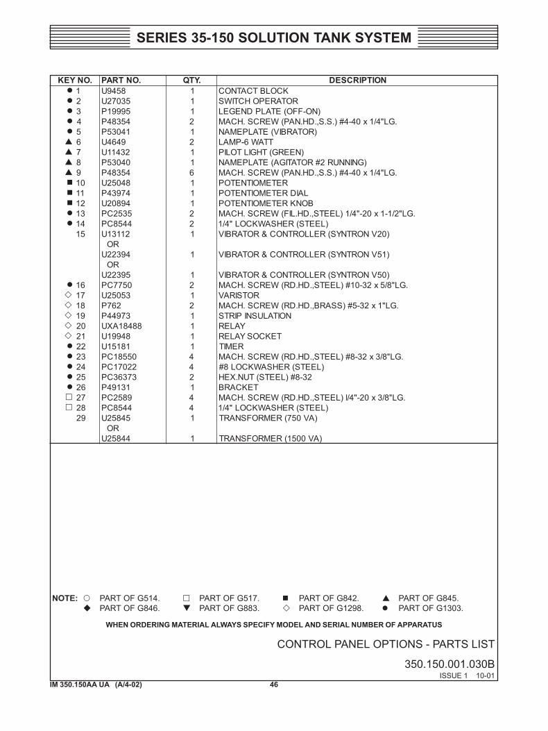
CONTROL PANEL OPTIONS - PARTS
350.150.001.030AISSUE 1 10-88
NOTE: FOR PARTS LIST, SEE DWGS. 350.150.001.030B&C.
46IM 350.150AA UA (A/4-02)
SERIES 35-150 SOLUTION TANK SYSTEM
CONTROL PANEL OPTIONS - PARTS LIST
350.150.001.030BISSUE 1 10-01
.ONYEK .ONTRAP .YTQ NOITPIRCSED1 8549U 1 KCOLBTCATNOC2 53072U 1 ROTAREPOHCTIWS3 59991P 1 )NO-FFO(ETALPDNEGEL4 45384P 2 .GL"4/1x04-4#).S.S,.DH.NAP(WERCS.HCAM5 14035P 1 )ROTARBIV(ETALPEMAN6 9464U 2 TTAW6-PMAL7 23411U 1 )NEERG(THGILTOLIP8 04035P 1 )GNINNUR2#ROTATIGA(ETALPEMAN9 45384P 6 .GL"4/1x04-4#).S.S,.DH.NAP(WERCS.HCAM01 84052U 1 RETEMOITNETOP11 47934P 1 LAIDRETEMOITNETOP21 49802U 1 BONKRETEMOITNETOP31 5352CP 2 .GL"2/1-1x02-"4/1)LEETS,.DH.LIF(WERCS.HCAM41 4458CP 2 )LEETS(REHSAWKCOL"4/151 21131U 1 )02VNORTNYS(RELLORTNOC&ROTARBIV
RO49322U 1 )15VNORTNYS(RELLORTNOC&ROTARBIV
RO59322U 1 )05VNORTNYS(RELLORTNOC&ROTARBIV
61 0577CP 2 .GL"8/5x23-01#)LEETS,.DH.DR(WERCS.HCAM71 35052U 1 ROTSIRAV81 267P 2 .GL"1x23-5#)SSARB,.DH.DR(WERCS.HCAM91 37944P 1 NOITALUSNIPIRTS02 88481AXU 1 YALER12 84991U 1 TEKCOSYALER22 18151U 1 REMIT32 05581CP 4 .GL"8/3x23-8#)LEETS,.DH.DR(WERCS.HCAM42 22071CP 4 )LEETS(REHSAWKCOL8#52 37363CP 2 23-8#)LEETS(TUN.XEH62 13194P 1 TEKCARB72 9852CP 4 .GL"8/3x02-"4/l)LEETS,.DH.DR(WERCS.HCAM82 4458CP 4 )LEETS(REHSAWKCOL"4/192 54852U 1 )AV057(REMROFSNART
RO44852U 1 )AV0051(REMROFSNART
WHEN ORDERING MATERIAL ALWAYS SPECIFY MODEL AND SERIAL NUMBER OF APPARATUS
NOTE: PART OF G514. PART OF G517. PART OF G842. PART OF G845.PART OF G846. PART OF G883. PART OF G1298. PART OF G1303.
47IM 350.150AA UA (A/4-02)
SERIES 35-150 SOLUTION TANK SYSTEM
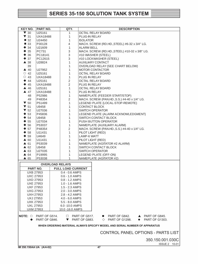
CONTROL PANEL OPTIONS - PARTS LIST
350.150.001.030CISSUE 2 10-01
.ONYEK .ONTRAP .YTQ NOITPIRCSED03 16152U 1 DRAOBYALERLATCO13 88481AXU 1 YALERNI-GULP23 05442U 1 ROTALOSI33 82103P 4 .GL"4/3x23-6#)LEETS,.DH.DR(WERCS.HCAM43 90612U 1 LLEBMRALA53 137CP 3 .GL"8/3x23-01#)LEETS,.DH.DR(WERCS.HCAM63 14181CP 3 )LEETS(REHSAW01#73 51621CP 3 )LEETS(REHSAWKCOL01#83 42882U 1 TCATNOCYRAILIXUA93 1 )WOLEBTRAHCEES(YALERDAOLREVO04 25972U 1 ROTCATNOCROTOM24 16152U 1 DRAOBYALERLATCO34 88481AXU 1 YALERNIGULP44 16152U 2 DRAOBYALERLATCO54 88481AXU 2 YALERNIGULP64 16152U 1 DRAOBYALERLATCO74 88481AXU 1 YALERNIGULP84 68925P 1 )POTS/TRATSREDEEF(ETALPEMAN94 45384P 2 .GL"4/1x04-4#).S.S,.DH.NAP(WERCS.HCAM05 99415P 1 )ETOMER-POTS-LACOL(ETALPDNEGEL15 8549U 1 KCOLBTCATNOC25 63072U 1 ROTAREPOHCTIWS35 63854P 1 )TNEMGDELWONKCAMRALA(ETALPDNEGEL45 8549U 1 KCOLBTCATNOCHCTIWS55 43072U 1 ROTAREPONOTTUBHSUP65 73035P 1 )MRALAYRAILIXUA(ETALPEMAN75 45384P 2 .GL"4/1x04-4#).S.S,.DH.NAP(WERCS.HCAM85 13411U 1 )DER(THGILTOLIP95 9464U 1 TTAW6-PMAL06 13411U 1 )DER(THGILTOLIP16 93035P 1 )MRALA2#ROTATIGA(ETALPEMAN26 8549U 1 KCOLBTCATNOCHCTIWS36 53072U 1 ROTAREPOHCTIWS46 59991P 1 )NO-FFO(ETALPDNEGEL56 83035P 1 )2#ROTATIGA(ETALPEMAN
SYALERDAOLREVO.ONTRAP TNERRUCDAOLLLUF35972BXU SPMA6.0-4.035972CXU SPMA0.1-6.035972DXU SPMA2.1-8.035972EXU SPMA6.1-0.135972FXU SPMA3.2-5.135972GXU SPMA0.3-0.235972HXU SPMA2.4-8.235972JXU SPMA0.6-0.435972KXU SPMA0.8-5.535972LXU SPMA0.01-0.635972MXU SPMA0.61-0.01
WHEN ORDERING MATERIAL ALWAYS SPECIFY MODEL AND SERIAL NUMBER OF APPARATUS
NOTE: PART OF G514. PART OF G517. PART OF G842. PART OF G845.PART OF G846. PART OF G883. PART OF G1298. PART OF G1303.
48IM 350.150AA UA (A/4-02)
SERIES 35-150 SOLUTION TANK SYSTEM
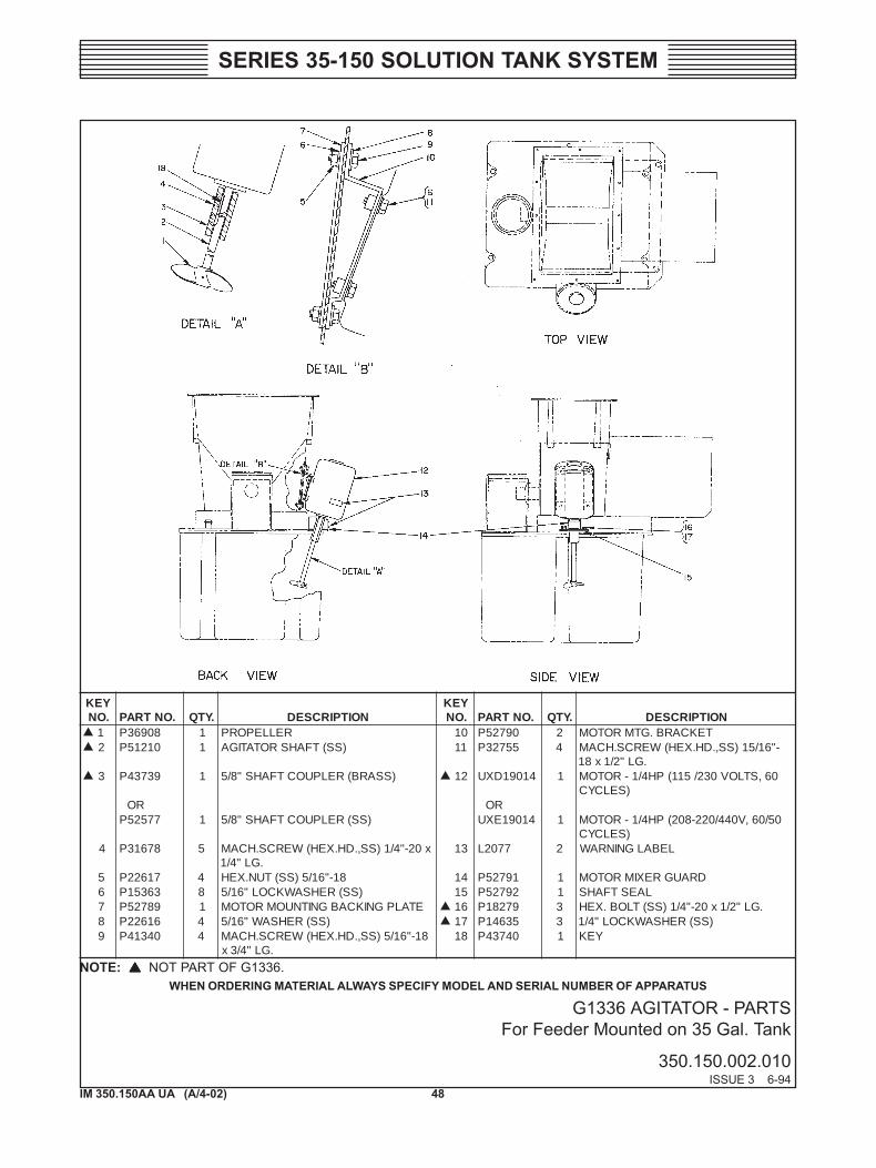
G1336 AGITATOR - PARTSFor Feeder Mounted on 35 Gal. Tank
350.150.002.010ISSUE 3 6-94
YEK.ON .ONTRAP .YTQ NOITPIRCSED
YEK.ON .ONTRAP .YTQ NOITPIRCSED
1 80963P 1 RELLEPORP 01 09725P 2 TEKCARB.GTMROTOM2 01215P 1 )SS(TFAHSROTATIGA 11 55723P 4 -"61/51)SS,.DH.XEH(WERCS.HCAM
.GL"2/1x813 93734P 1 )SSARB(RELPUOCTFAHS"8/5 21 41091DXU 1 06,STLOV032/511(PH4/1-ROTOM
)SELCYCRO RO
77525P 1 )SS(RELPUOCTFAHS"8/5 41091EXU 1 05/06,V044/022-802(PH4/1-ROTOM)SELCYC
4 87613P 5 x02-"4/1)SS,.DH.XEH(WERCS.HCAM.GL"4/1
31 7702L 2 LEBALGNINRAW
5 71622P 4 81-"61/5)SS(TUN.XEH 41 19725P 1 DRAUGREXIMROTOM6 36351P 8 )SS(REHSAWKCOL"61/5 51 29725P 1 LAESTFAHS7 98725P 1 ETALPGNIKCABGNITNUOMROTOM 61 97281P 3 .GL"2/1x02-"4/1)SS(TLOB.XEH8 61622P 4 )SS(REHSAW"61/5 71 53641P 3 )SS(REHSAWKCOL"4/19 04314P 4 81-"61/5)SS,.DH.XEH(WERCS.HCAM
.GL"4/3x81 04734P 1 YEK
WHEN ORDERING MATERIAL ALWAYS SPECIFY MODEL AND SERIAL NUMBER OF APPARATUSNOTE: NOT PART OF G1336.
49IM 350.150AA UA (A/4-02)
SERIES 35-150 SOLUTION TANK SYSTEM
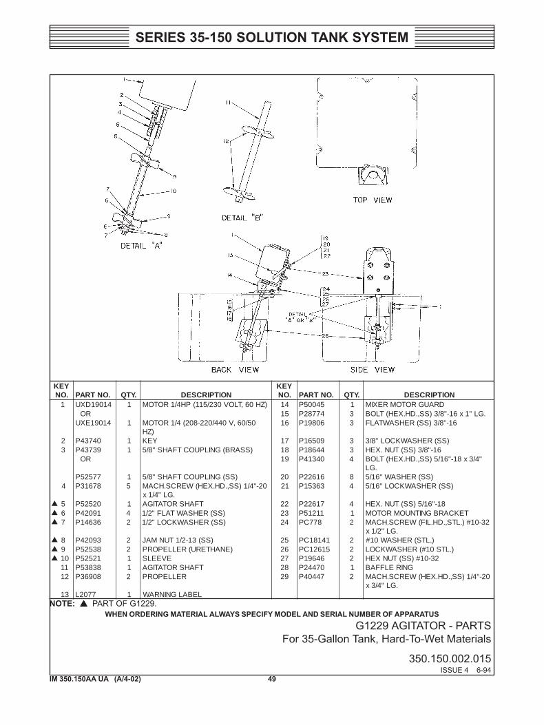
G1229 AGITATOR - PARTSFor 35-Gallon Tank, Hard-To-Wet Materials
350.150.002.015ISSUE 4 6-94
YEK.ON .ONTRAP .YTQ NOITPIRCSED
YEK.ON .ONTRAP .YTQ NOITPIRCSED
1 41091DXU 1 )ZH06,TLOV032/511(PH4/1ROTOM 41 54005P 1 DRAUGROTOMREXIMRO 51 47782P 3 .GL"1x61-"8/3)SS,.DH.XEH(TLOB
41091EXU 1 05/06,V044/022-802(4/1ROTOM)ZH
61 60891P 3 61-"8/3)SS(REHSAWTALF
2 04734P 1 YEK 71 90561P 3 )SS(REHSAWKCOL"8/33 93734P 1 )SSARB(GNILPUOCTFAHS"8/5 81 44681P 3 61-"8/3)SS(TUN.XEH
RO 91 04314P 4 "4/3x81-"61/5)SS,.DH.XEH(TLOB.GL
77525P 1 )SS(GNILPUOCTFAHS"8/5 02 61622P 8 )SS(REHSAW"61/54 87613P 5 02-"4/1)SS,.DH.XEH(WERCS.HCAM
.GL"4/1x12 36351P 4 )SS(REHSAWKCOL"61/5
5 02525P 1 TFAHSROTATIGA 22 71622P 4 81-"61/5)SS(TUN.XEH6 19024P 4 )SS(REHSAWTALF"2/1 32 11215P 1 TEKCARBGNITNUOMROTOM7 63641P 2 )SS(REHSAWKCOL"2/1 42 877CP 2 23-01#).LTS,.DH.LIF(WERCS.HCAM
.GL"2/1x8 39024P 2 )SS(31-2/1TUNMAJ 52 14181CP 2 ).LTS(REHSAW01#9 83525P 2 )ENAHTERU(RELLEPORP 62 51621CP 2 ).LTS01#(REHSAWKCOL01 12525P 1 EVEELS 72 64691P 2 23-01#)SS(TUNXEH11 83835P 1 TFAHSROTATIGA 82 07442P 1 GNIRELFFAB21 80963P 2 RELLEPORP 92 74404P 2 02-"4/1)SS,.DH.XEH(WERCS.HCAM
.GL"4/3x31 7702L 1 LEBALGNINRAW
WHEN ORDERING MATERIAL ALWAYS SPECIFY MODEL AND SERIAL NUMBER OF APPARATUSNOTE: PART OF G1229.
50IM 350.150AA UA (A/4-02)
SERIES 35-150 SOLUTION TANK SYSTEM
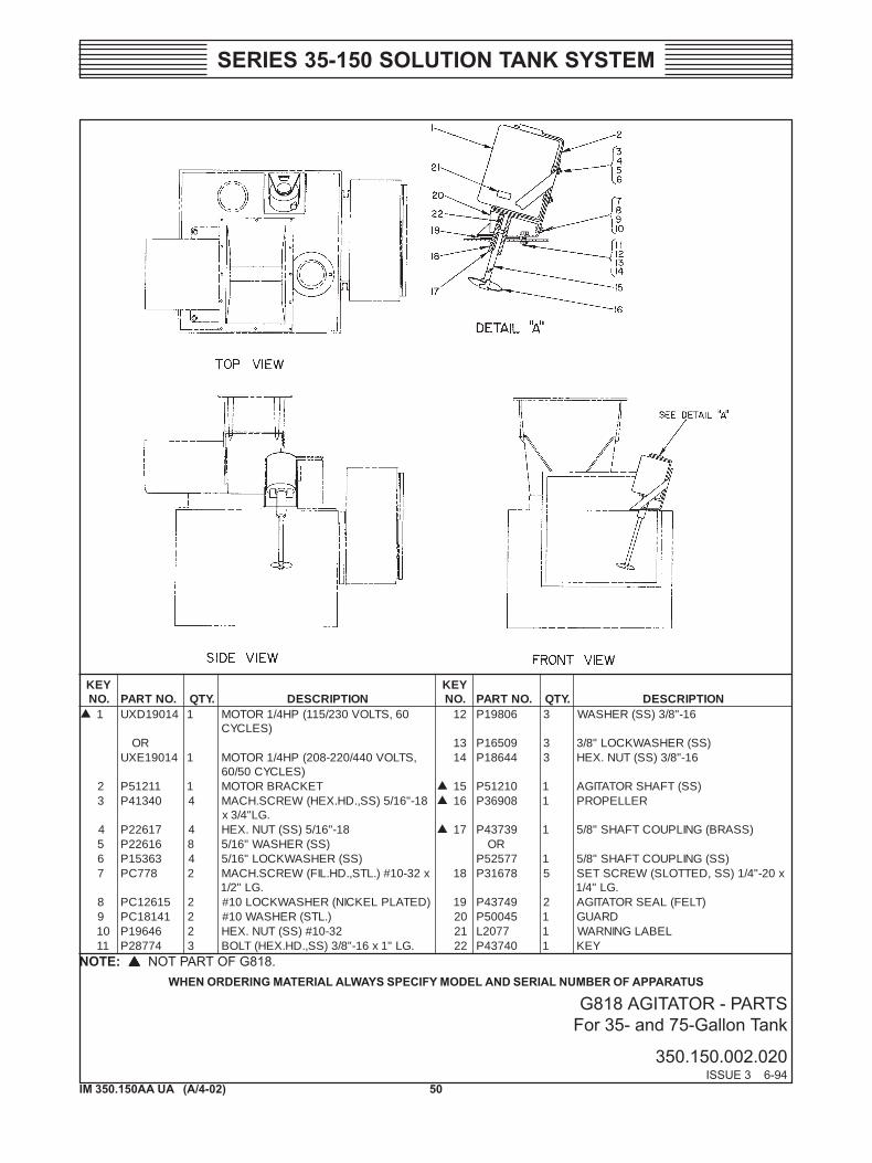
G818 AGITATOR - PARTSFor 35- and 75-Gallon Tank
350.150.002.020ISSUE 3 6-94
YEK.ON .ONTRAP .YTQ NOITPIRCSED
YEK.ON .ONTRAP .YTQ NOITPIRCSED
1 41091DXU 1 06,STLOV032/511(PH4/1ROTOM)SELCYC
21 60891P 3 61-"8/3)SS(REHSAW
RO 31 90561P 3 )SS(REHSAWKCOL"8/341091EXU 1 ,STLOV044/022-802(PH4/1ROTOM
)SELCYC05/0641 44681P 3 61-"8/3)SS(TUN.XEH
2 11215P 1 TEKCARBROTOM 51 01215P 1 )SS(TFAHSROTATIGA3 04314P 4 81-"61/5)SS,.DH.XEH(WERCS.HCAM
.GL"4/3x61 80963P 1 RELLEPORP
4 71622P 4 81-"61/5)SS(TUN.XEH 71 93734P 1 )SSARB(GNILPUOCTFAHS"8/55 61622P 8 )SS(REHSAW"61/5 RO6 36351P 4 )SS(REHSAWKCOL"61/5 77525P 1 )SS(GNILPUOCTFAHS"8/57 877CP 2 x23-01#).LTS,.DH.LIF(WERCS.HCAM
.GL"2/181 87613P 5 x02-"4/1)SS,DETTOLS(WERCSTES
.GL"4/18 51621CP 2 )DETALPLEKCIN(REHSAWKCOL01# 91 94734P 2 )TLEF(LAESROTATIGA9 14181CP 2 ).LTS(REHSAW01# 02 54005P 1 DRAUG01 64691P 2 23-01#)SS(TUN.XEH 12 7702L 1 LEBALGNINRAW11 47782P 3 .GL"1x61-"8/3)SS,.DH.XEH(TLOB 22 04734P 1 YEK
WHEN ORDERING MATERIAL ALWAYS SPECIFY MODEL AND SERIAL NUMBER OF APPARATUSNOTE: NOT PART OF G818.
51IM 350.150AA UA (A/4-02)
SERIES 35-150 SOLUTION TANK SYSTEM
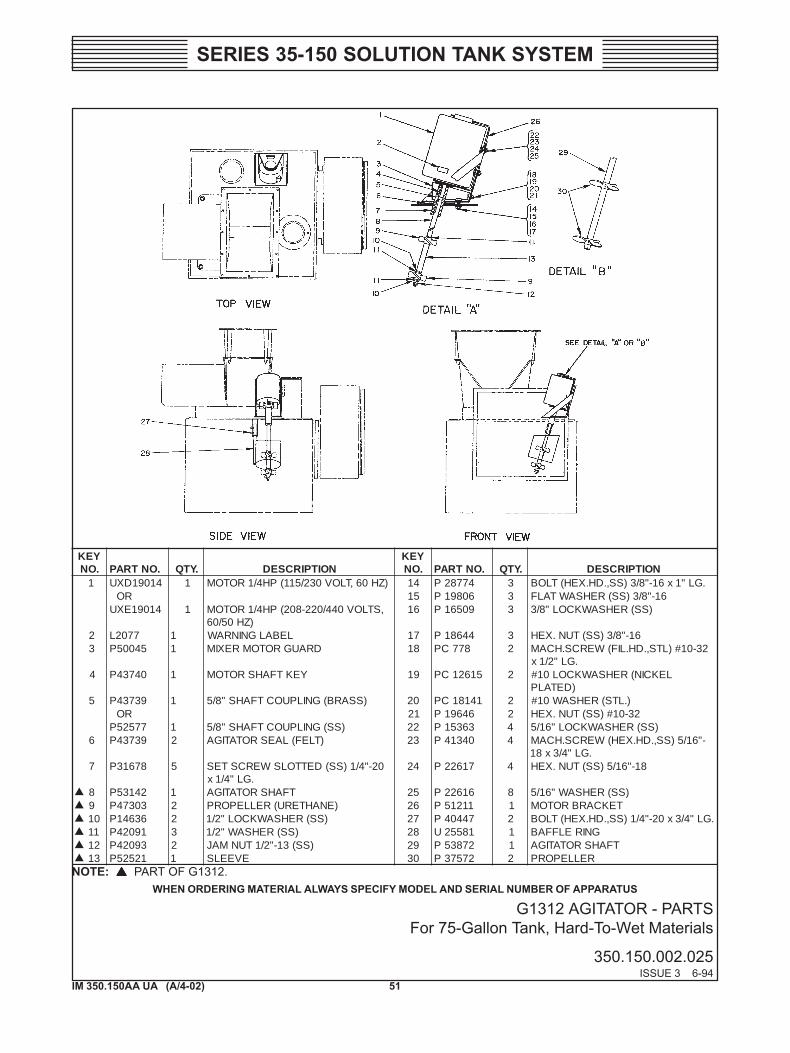
G1312 AGITATOR - PARTSFor 75-Gallon Tank, Hard-To-Wet Materials
350.150.002.025ISSUE 3 6-94
YEK.ON .ONTRAP .YTQ NOITPIRCSED
YEK.ON .ONTRAP .YTQ NOITPIRCSED
1 41091DXU 1 )ZH06,TLOV032/511(PH4/1ROTOM 41 47782P 3 .GL"1x61-"8/3)SS,.DH.XEH(TLOBRO 51 60891P 3 61-"8/3)SS(REHSAWTALF
41091EXU 1 ,STLOV044/022-802(PH4/1ROTOM)ZH05/06
61 90561P 3 )SS(REHSAWKCOL"8/3
2 7702L 1 LEBALGNINRAW 71 44681P 3 61-"8/3)SS(TUN.XEH3 54005P 1 DRAUGROTOMREXIM 81 877CP 2 23-01#)LTS,.DH.LIF(WERCS.HCAM
.GL"2/1x4 04734P 1 YEKTFAHSROTOM 91 51621CP 2 LEKCIN(REHSAWKCOL01#
)DETALP5 93734P 1 )SSARB(GNILPUOCTFAHS"8/5 02 14181CP 2 ).LTS(REHSAW01#
RO 12 64691P 2 23-01#)SS(TUN.XEH77525P 1 )SS(GNILPUOCTFAHS"8/5 22 36351P 4 )SS(REHSAWKCOL"61/5
6 93734P 2 )TLEF(LAESROTATIGA 32 04314P 4 -"61/5)SS,.DH.XEH(WERCS.HCAM.GL"4/3x81
7 87613P 5 02-"4/1)SS(DETTOLSWERCSTES.GL"4/1x
42 71622P 4 81-"61/5)SS(TUN.XEH
8 24135P 1 TFAHSROTATIGA 52 61622P 8 )SS(REHSAW"61/59 30374P 2 )ENAHTERU(RELLEPORP 62 11215P 1 TEKCARBROTOM01 63641P 2 )SS(REHSAWKCOL"2/1 72 74404P 2 .GL"4/3x02-"4/1)SS,.DH.XEH(TLOB11 19024P 3 )SS(REHSAW"2/1 82 18552U 1 GNIRELFFAB21 39024P 2 )SS(31-"2/1TUNMAJ 92 27835P 1 TFAHSROTATIGA31 12525P 1 EVEELS 03 27573P 2 RELLEPORP
WHEN ORDERING MATERIAL ALWAYS SPECIFY MODEL AND SERIAL NUMBER OF APPARATUSNOTE: PART OF G1312.
52IM 350.150AA UA (A/4-02)
SERIES 35-150 SOLUTION TANK SYSTEM
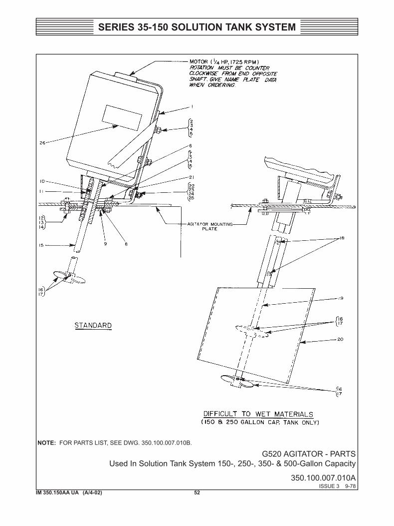
G520 AGITATOR - PARTSUsed In Solution Tank System 150-, 250-, 350- & 500-Gallon Capacity
350.100.007.010AISSUE 3 9-78
NOTE: FOR PARTS LIST, SEE DWG. 350.100.007.010B.
53IM 350.150AA UA (A/4-02)
SERIES 35-150 SOLUTION TANK SYSTEM
SERIES 35-100 SOLUTION TANK SYSTEM - G420 AGITATOR FOR 150, 250, 350 & 500GALLON SOLUTION TANKS - PARTS LIST
350.100.007.010BISSUE 7 1-97
.ONYEK .ONTRAP .YTQ NOITPIRCSED1 11215P 1 TEKCARBROTOM2 04314P 4 .GL"4/3x81-"61/5)SS,.DH.XEH(WERCSPAC3 61622P 21 )SS(REHSAW"61/54 36351P 8 )SS(REHSAWKCOL"61/55 71622P 8 81-"61/5)SS(TUN.XEH6 93734P 1 GNILPUOC7 59504P 4 .GL"1x81-"61/5)SS,.DH.XEH(WERCSPAC8 94734P 2 LAESTLEF9 37704P 1 RENIATERTLEF01 04734P 1 YEKTFAHSROTOM11 87613P 5 .GL"4/1x02-"4/1)SS,.DH.KCOS(WERCSTES21 07792P 4 .GL"1x02-"4/1)SS,.DH.XEH(WERCSPAC31 31792P 4 )4171.ONFOORPEKAHS(REHSAWKCOL41 53891P 4 02-"4/1)SS(TUN.XEH51 30144P 1 )NOLLAG051(TFAHS
RO50144P 1 )NOLLAG052(TFAHS
RO40144P 1 )NOLLAG053(TFAHS
RO24594P 1 )NOLLAG005(TFAHS
61 27573P 1 )71METISEDULCNI(RELLEPORP71 86323P 2 .GL"4/1x42-01#)SS,.DH.KCOS(WERCSTES81 97281P 2 .GL"2/1x02-"4/1)SS,.DH.XEH(WERCSPAC91 45194P 1 )SLAIRETAMTEWOTTLUCIFFID(TFAHS02 78232U 1 )SLAIRETAMTEWOTTLUCIFFID(GNIRELFFAB12 54005P 1 DRAUG22 877CP 2 .GL"2/1x23-01#)LEETS,.DH.LIF(WERCS.HCAM32 51621CP 2 )LEETS(REHSAWKCOL01#42 14181CP 2 )LEETS(REHSAW01#52 64691P 2 23-01#)SS(TUN.XEH62 7702L 1 LEBALGNINRAW
WHEN ORDERING MATERIAL, ALWAYS SPECIFY MODEL AND SERIAL NUMBER OF APPARATUS.
NOTES: NOT PART OF G520.FOR HARD-TO-WET MATERIALS, (2) REQ’D. OF KEY NO. 16 & (4) REQ’D. OF KEY NO. 17.
54IM 350.150AA UA (A/4-02)
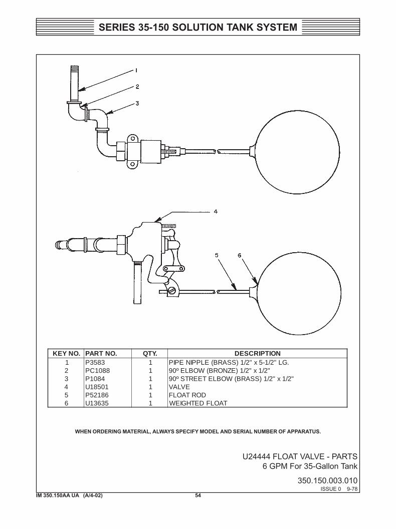
SERIES 35-150 SOLUTION TANK SYSTEM
U24444 FLOAT VALVE - PARTS6 GPM For 35-Gallon Tank
350.150.003.010ISSUE 0 9-78
.ONYEK .ONTRAP .YTQ NOITPIRCSED1 3853P 1 .GL"2/1-5x"2/1)SSARB(ELPPINEPIP2 8801CP 1 "2/1x"2/1)EZNORB(WOBLEº093 4801P 1 "2/1x"2/1)SSARB(WOBLETEERTSº094 10581U 1 EVLAV5 68125P 1 DORTAOLF6 53631U 1 TAOLFDETHGIEW
WHEN ORDERING MATERIAL, ALWAYS SPECIFY MODEL AND SERIAL NUMBER OF APPARATUS.
55IM 350.150AA UA (A/4-02)
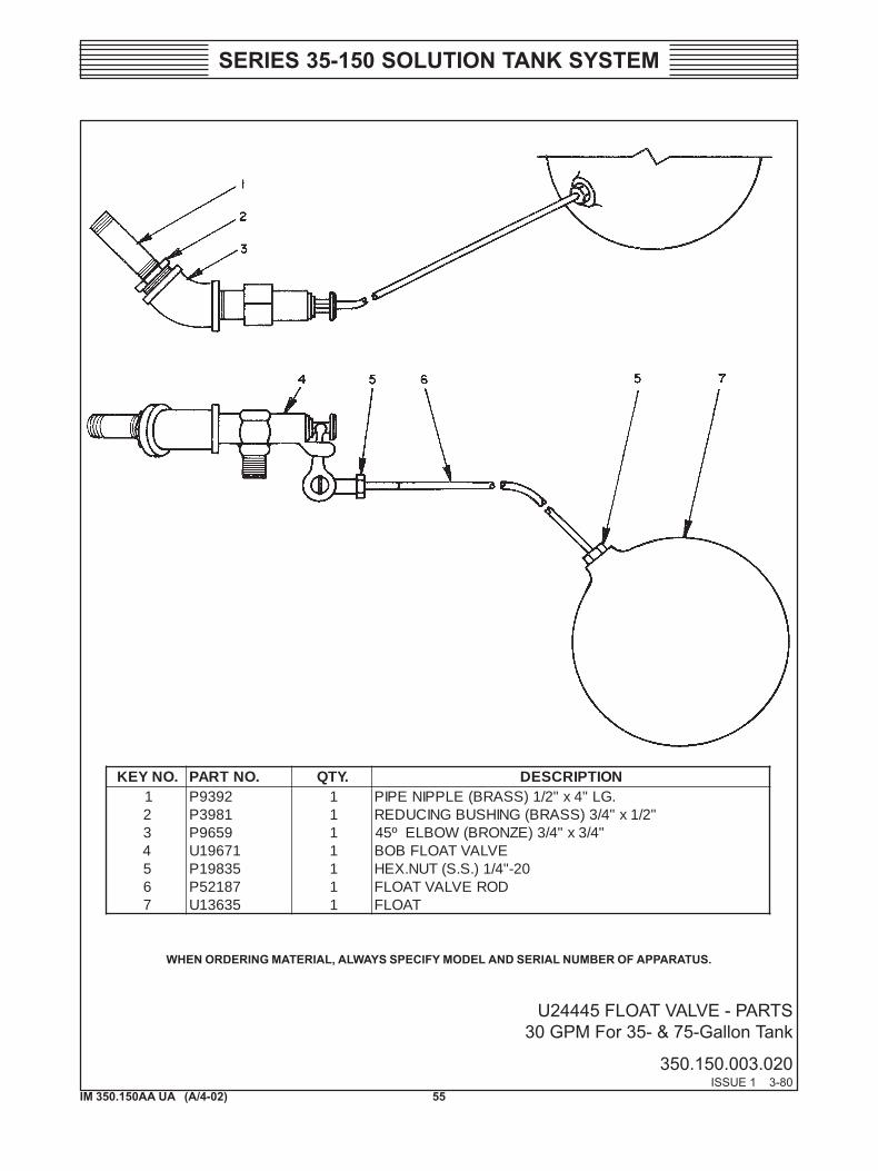
SERIES 35-150 SOLUTION TANK SYSTEM
U24445 FLOAT VALVE - PARTS30 GPM For 35- & 75-Gallon Tank
350.150.003.020ISSUE 1 3-80
WHEN ORDERING MATERIAL, ALWAYS SPECIFY MODEL AND SERIAL NUMBER OF APPARATUS.
.ONYEK .ONTRAP .YTQ NOITPIRCSED1 2939P 1 .GL"4x"2/1)SSARB(ELPPINEPIP2 1893P 1 "2/1x"4/3)SSARB(GNIHSUBGNICUDER3 9569P 1 "4/3x"4/3)EZNORB(WOBLEº544 17691U 1 EVLAVTAOLFBOB5 53891P 1 02-"4/1).S.S(TUN.XEH6 78125P 1 DOREVLAVTAOLF7 53631U 1 TAOLF
56IM 350.150AA UA (A/4-02)
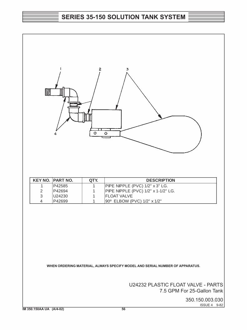
SERIES 35-150 SOLUTION TANK SYSTEM
U24232 PLASTIC FLOAT VALVE - PARTS7.5 GPM For 25-Gallon Tank
350.150.003.030ISSUE 4 9-82
.ONYEK .ONTRAP .YTQ NOITPIRCSED1 58524P 1 .GL"3x"2/1)CVP(ELPPINEPIP2 49624P 1 .GL"2/1-1x"2/1)CVP(ELPPINEPIP3 03242U 1 EVLAVTAOLF4 99624P 1 "2/1x"2/1)CVP(WOBLEº09
WHEN ORDERING MATERIAL, ALWAYS SPECIFY MODEL AND SERIAL NUMBER OF APPARATUS.
57IM 350.150AA UA (A/4-02)
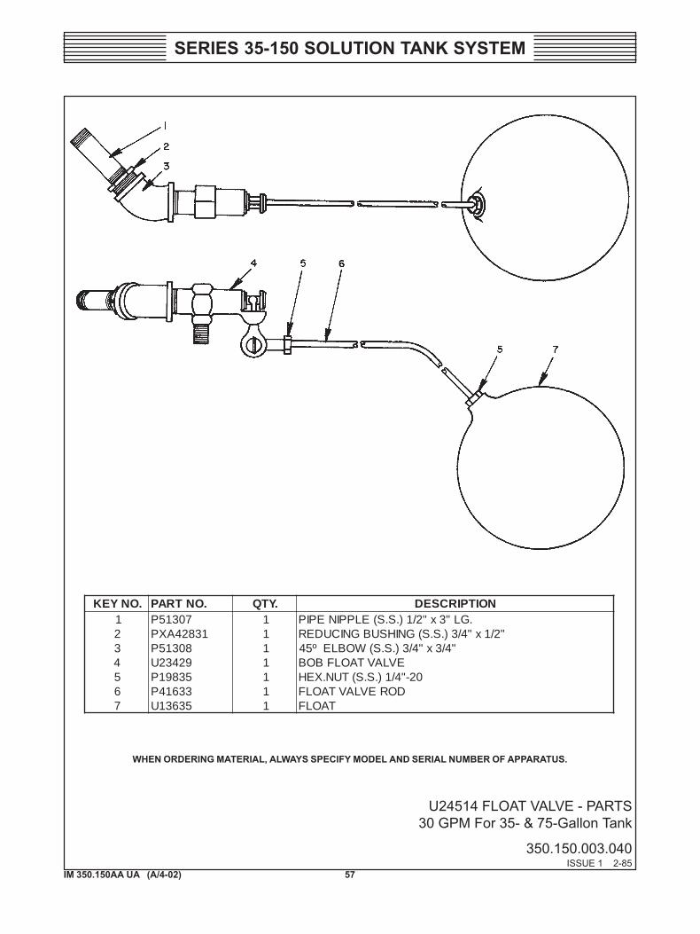
SERIES 35-150 SOLUTION TANK SYSTEM
U24514 FLOAT VALVE - PARTS30 GPM For 35- & 75-Gallon Tank
350.150.003.040ISSUE 1 2-85
.ONYEK .ONTRAP .YTQ NOITPIRCSED1 70315P 1 .GL"3x"2/1).S.S(ELPPINEPIP2 13824AXP 1 "2/1x"4/3).S.S(GNIHSUBGNICUDER3 80315P 1 "4/3x"4/3).S.S(WOBLEº544 92432U 1 EVLAVTAOLFBOB5 53891P 1 02-"4/1).S.S(TUN.XEH6 33614P 1 DOREVLAVTAOLF7 53631U 1 TAOLF
WHEN ORDERING MATERIAL, ALWAYS SPECIFY MODEL AND SERIAL NUMBER OF APPARATUS.

58IM 350.150AA UA (A/4-02)
SERIES 35-150 SOLUTION TANK SYSTEM
YEK.ON .ONTRAP .YTQ NOITPIRCSED
27691U)SSARB(
03432U).S.S(
1 53891P 4 02-"4/1).S.S(TUNXEH2 88891P 6 ).S.S(REHSAW"4/13 85614P 1 TEKSAG4 56904P 1 KCOLB5 76904P 4 .GL"4/3-1x02-"4/1).S.S,.DH.LIF(WERCS.HCAM6 17691U 1 EVLAVTAOLF
92432U 1 EVLAVTAOLF7 33614P 1 DORTAOLF8 53631U 1 TAOLF
SERIES 35-100 SOLUTION TANK SYSTEM - 30 GPM FLOAT VALVE UNIT FOR 150 & 250 GALLON SOLUTION TANKS - PARTS
311.000.30.034ISSUE 6 1-97
WHEN ORDERING MATERIAL, ALWAYS SPECIFY MODEL AND SERIAL NUMBER OF APPARATUS.
NOTE: FURNISHED NOT FURNISHED
59IM 350.150AA UA (A/4-02)
SERIES 35-150 SOLUTION TANK SYSTEM
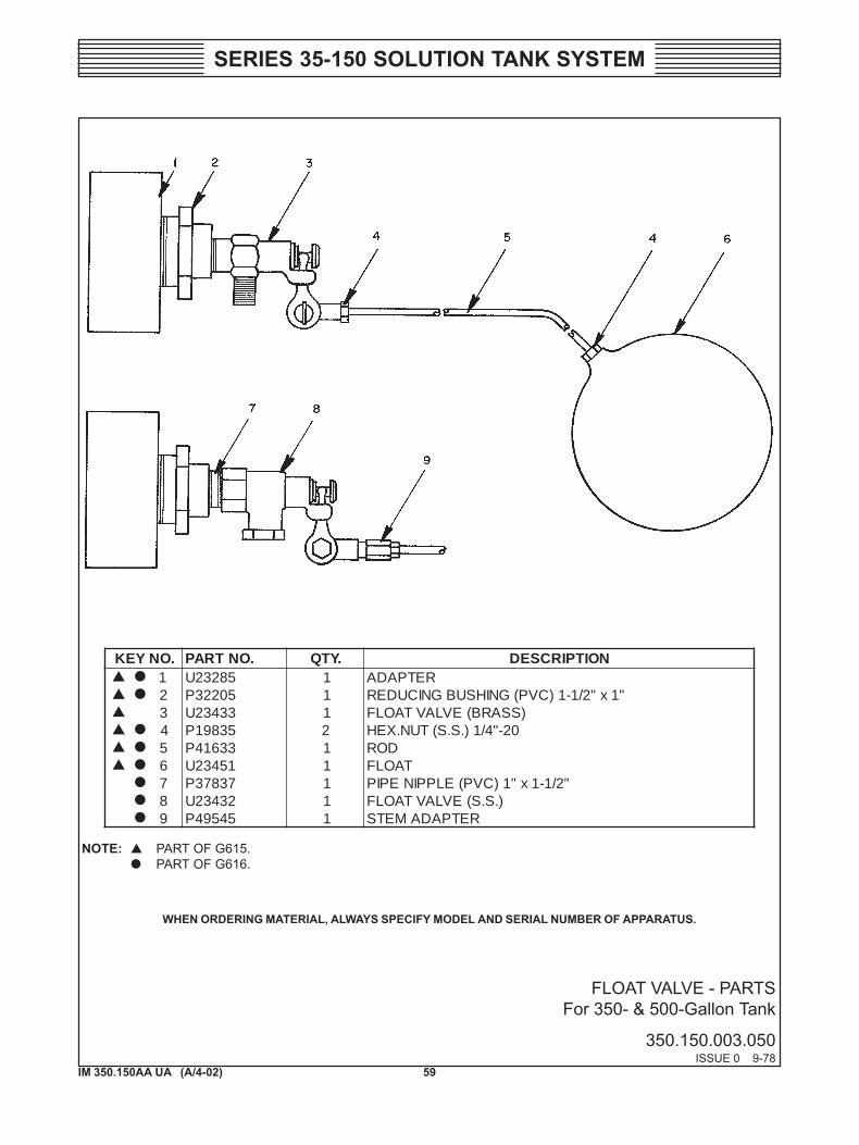
FLOAT VALVE - PARTSFor 350- & 500-Gallon Tank
350.150.003.050ISSUE 0 9-78
.ONYEK .ONTRAP .YTQ NOITPIRCSED1 58232U 1 RETPADA2 50223P 1 "1x"2/1-1)CVP(GNIHSUBGNICUDER3 33432U 1 )SSARB(EVLAVTAOLF4 53891P 2 02-"4/1).S.S(TUN.XEH5 33614P 1 DOR6 15432U 1 TAOLF7 73873P 1 "2/1-1x"1)CVP(ELPPINEPIP8 23432U 1 ).S.S(EVLAVTAOLF9 54594P 1 RETPADAMETS
WHEN ORDERING MATERIAL, ALWAYS SPECIFY MODEL AND SERIAL NUMBER OF APPARATUS.
NOTE: PART OF G615.PART OF G616.
60IM 350.150AA UA (A/4-02)
SERIES 35-150 SOLUTION TANK SYSTEM
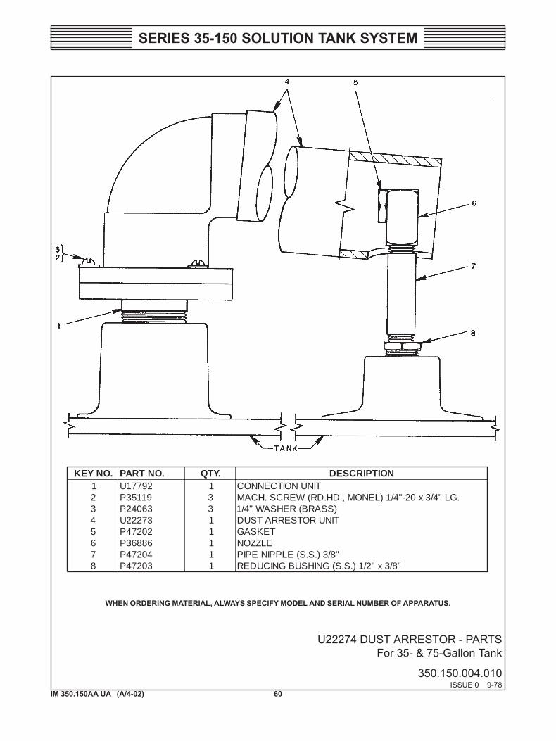
U22274 DUST ARRESTOR - PARTSFor 35- & 75-Gallon Tank
350.150.004.010ISSUE 0 9-78
.ONYEK .ONTRAP .YTQ NOITPIRCSED1 29771U 1 TINUNOITCENNOC2 91153P 3 .GL"4/3x02-"4/1)LENOM,.DH.DR(WERCS.HCAM3 36042P 3 )SSARB(REHSAW"4/14 37222U 1 TINUROTSERRATSUD5 20274P 1 TEKSAG6 68863P 1 ELZZON7 40274P 1 "8/3).S.S(ELPPINEPIP8 30274P 1 "8/3x"2/1).S.S(GNIHSUBGNICUDER
WHEN ORDERING MATERIAL, ALWAYS SPECIFY MODEL AND SERIAL NUMBER OF APPARATUS.
61IM 350.150AA UA (A/4-02)
SERIES 35-150 SOLUTION TANK SYSTEM
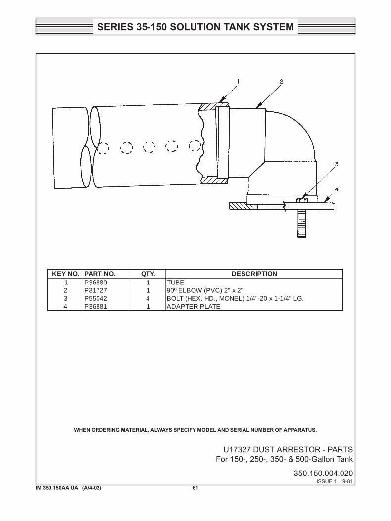
U17327 DUST ARRESTOR - PARTSFor 150-, 250-, 350- & 500-Gallon Tank
350.150.004.020ISSUE 1 9-81
.ONYEK .ONTRAP .YTQ NOITPIRCSED1 08863P 1 EBUT2 72713P 1 "2x"2)CVP(WOBLEº093 24055P 4 .GL"4/1-1x02-"4/1)LENOM,.DH.XEH(TLOB4 18863P 1 ETALPRETPADA
WHEN ORDERING MATERIAL, ALWAYS SPECIFY MODEL AND SERIAL NUMBER OF APPARATUS.
62IM 350.150AA UA (A/4-02)
SERIES 35-150 SOLUTION TANK SYSTEM
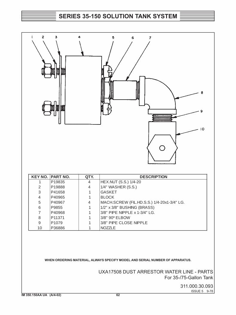
UXA17508 DUST ARRESTOR WATER LINE - PARTSFor 35-/75-Gallon Tank
311.000.30.093ISSUE 5 9-78
WHEN ORDERING MATERIAL, ALWAYS SPECIFY MODEL AND SERIAL NUMBER OF APPARATUS.
.ONYEK .ONTRAP .YTQ NOITPIRCSED1 53891P 4 02-4/1).S.S(TUN.XEH2 88891P 4 ).S.S(REHSAW"4/13 85614P 1 TEKSAG4 56904P 1 KCOLB5 76904P 4 .GL"4/3-1x02-4/1).S.S.DH.LIF(WERCS.HCAM6 5589P 1 )SSARB(GNIHSUB"8/3x"2/17 86904P 1 .GL"4/3-1xELPPINEPIP"8/38 17311P 1 WOBLEº09"8/39 9701P 1 ELPPINESOLCEPIP"8/301 68863P 1 ELZZON
63IM 350.150AA UA (A/4-02)
SERIES 35-150 SOLUTION TANK SYSTEM
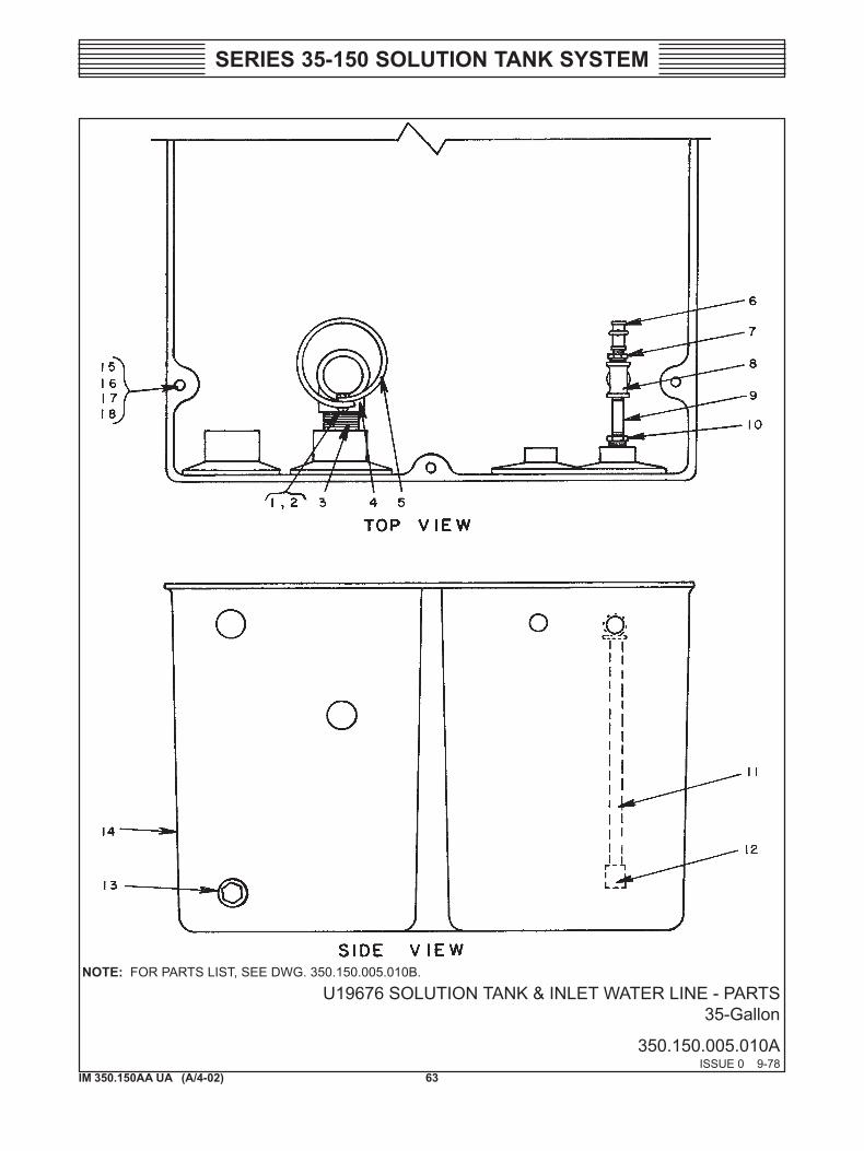
U19676 SOLUTION TANK & INLET WATER LINE - PARTS35-Gallon
350.150.005.010AISSUE 0 9-78
NOTE: FOR PARTS LIST, SEE DWG. 350.150.005.010B.
64IM 350.150AA UA (A/4-02)
SERIES 35-150 SOLUTION TANK SYSTEM
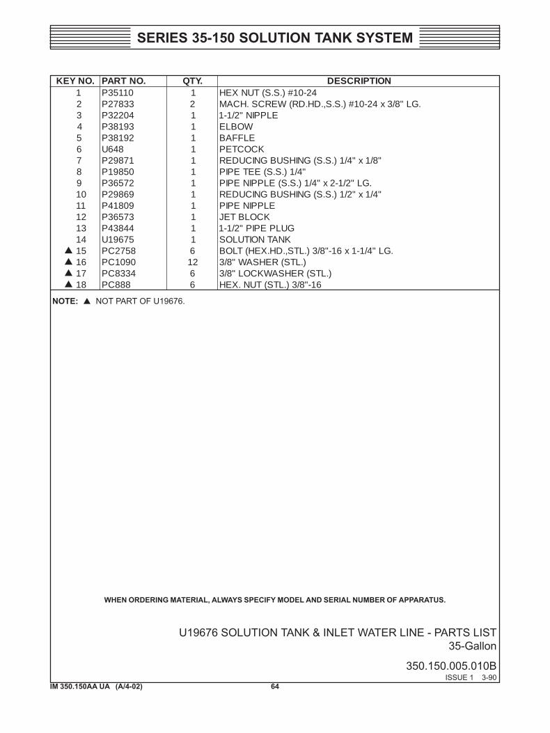
U19676 SOLUTION TANK & INLET WATER LINE - PARTS LIST35-Gallon
350.150.005.010BISSUE 1 3-90
.ONYEK .ONTRAP .YTQ NOITPIRCSED1 01153P 1 42-01#).S.S(TUNXEH2 33872P 2 .GL"8/3x42-01#).S.S,.DH.DR(WERCS.HCAM3 40223P 1 ELPPIN"2/1-14 39183P 1 WOBLE5 29183P 1 ELFFAB6 846U 1 KCOCTEP7 17892P 1 "8/1x"4/1).S.S(GNIHSUBGNICUDER8 05891P 1 "4/1).S.S(EETEPIP9 27563P 1 .GL"2/1-2x"4/1).S.S(ELPPINEPIP01 96892P 1 "4/1x"2/1).S.S(GNIHSUBGNICUDER11 90814P 1 ELPPINEPIP21 37563P 1 KCOLBTEJ31 44834P 1 GULPEPIP"2/1-141 57691U 1 KNATNOITULOS51 8572CP 6 .GL"4/1-1x61-"8/3).LTS,.DH.XEH(TLOB61 0901CP 21 ).LTS(REHSAW"8/371 4338CP 6 ).LTS(REHSAWKCOL"8/381 888CP 6 61-"8/3).LTS(TUN.XEH
WHEN ORDERING MATERIAL, ALWAYS SPECIFY MODEL AND SERIAL NUMBER OF APPARATUS.
NOTE: NOT PART OF U19676.
65IM 350.150AA UA (A/4-02)
SERIES 35-150 SOLUTION TANK SYSTEM
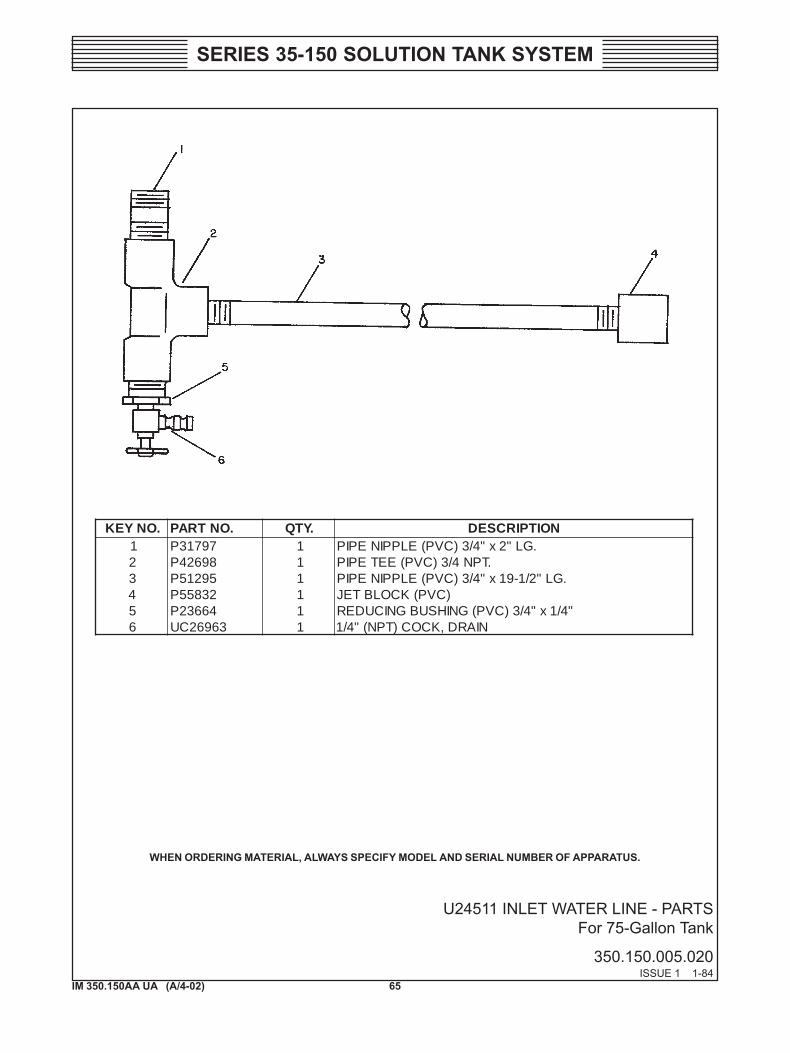
U24511 INLET WATER LINE - PARTS For 75-Gallon Tank
350.150.005.020ISSUE 1 1-84
.ONYEK .ONTRAP .YTQ NOITPIRCSED1 79713P 1 .GL"2x"4/3)CVP(ELPPINEPIP2 89624P 1 .TPN4/3)CVP(EETEPIP3 59215P 1 .GL"2/1-91x"4/3)CVP(ELPPINEPIP4 23855P 1 )CVP(KCOLBTEJ5 46632P 1 "4/1x"4/3)CVP(GNIHSUBGNICUDER6 36962CU 1 NIARD,KCOC)TPN("4/1
WHEN ORDERING MATERIAL, ALWAYS SPECIFY MODEL AND SERIAL NUMBER OF APPARATUS.
66IM 350.150AA UA (A/4-02)
SERIES 35-150 SOLUTION TANK SYSTEM
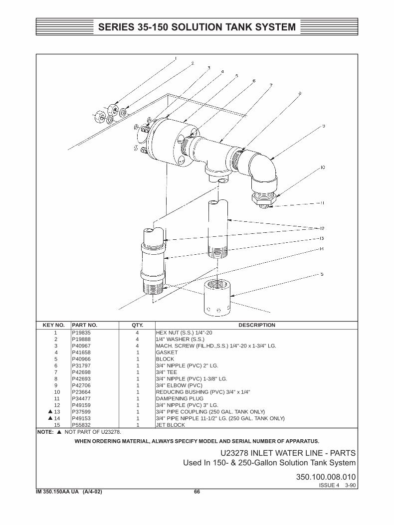
U23278 INLET WATER LINE - PARTS Used In 150- & 250-Gallon Solution Tank System
350.100.008.010ISSUE 4 3-90
WHEN ORDERING MATERIAL, ALWAYS SPECIFY MODEL AND SERIAL NUMBER OF APPARATUS. NOTE: NOT PART OF U23278.
.ONYEK .ONTRAP .YTQ NOITPIRCSED1 53891P 4 02-"4/1).S.S(TUNXEH2 88891P 4 ).S.S(REHSAW"4/13 76904P 4 .GL"4/3-1x02-"4/1).S.S,.DH.LIF(WERCS.HCAM4 85614P 1 TEKSAG5 66904P 1 KCOLB6 79713P 1 .GL"2)CVP(ELPPIN"4/37 89624P 1 EET"4/38 39624P 1 .GL"8/3-1)CVP(ELPPIN"4/39 60724P 1 )CVP(WOBLE"4/301 46632P 1 "4/1x"4/3)CVP(GNIHSUBGNICUDER11 77443P 1 GULPGNINEPMAD21 95194P 1 .GL"3)CVP(ELPPIN"4/331 99573P 1 )YLNOKNAT.LAG052(GNILPUOCEPIP"4/341 35194P 1 )YLNOKNAT.LAG052(.GL"2/1-11ELPPINEPIP"4/351 23855P 1 KCOLBTEJ
67IM 350.150AA UA (A/4-02)
SERIES 35-150 SOLUTION TANK SYSTEM
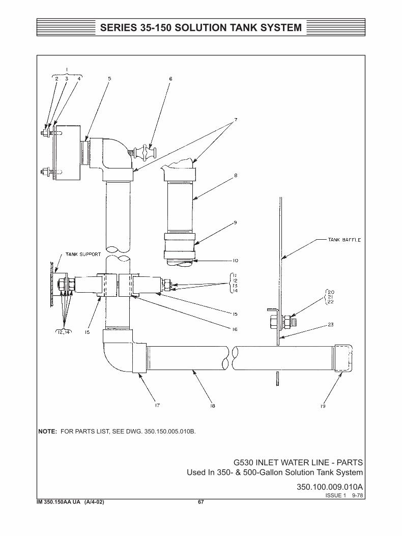
G530 INLET WATER LINE - PARTS Used In 350- & 500-Gallon Solution Tank System
350.100.009.010AISSUE 1 9-78
NOTE: FOR PARTS LIST, SEE DWG. 350.150.005.010B.
68IM 350.150AA UA (A/4-02)
SERIES 35-150 SOLUTION TANK SYSTEM
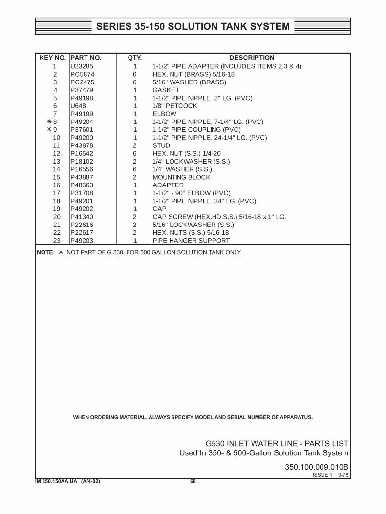
G530 INLET WATER LINE - PARTS LIST Used In 350- & 500-Gallon Solution Tank System
350.100.009.010BISSUE 1 9-78
.ONYEK .ONTRAP .YTQ NOITPIRCSED1 58232U 1 )4&3,2SMETISEDULCNI(RETPADAEPIP"2/1-12 4785CP 6 81-61/5)SSARB(TUN.XEH3 5742CP 6 )SSARB(REHSAW"61/54 97473P 1 TEKSAG5 89194P 1 )CVP(.GL"2,ELPPINEPIP"2/1-16 846U 1 KCOCTEP"8/17 99194P 1 WOBLE8 40294P 1 )CVP(.GL"4/1-7,ELPPINEPIP"2/1-19 10673P 1 )CVP(GNILPUOCEPIP"2/1-101 00294P 1 )CVP(.GL"4/1-42,ELPPINEPIP"2/1-111 87834P 2 DUTS21 24561P 6 02-4/1).S.S(TUN.XEH31 20181P 2 ).S.S(REHSAWKCOL"4/141 65561P 6 ).S.S(REHSAW"4/151 78834P 2 KCOLBGNITNUOM61 36584P 1 RETPADA71 80713P 1 )CVP(WOBLE°09-"2/1-181 10294P 1 )CVP(.GL"43,ELPPINEPIP"2/1-191 20294P 1 PAC02 04314P 2 .GL"1x81-61/5).S.S.DH.XEH(WERCSPAC12 61622P 2 ).S.S(REHSAWKCOL"61/522 71622P 2 81-61/5).S.S(STUN.XEH32 30294P 1 TROPPUSREGNAHEPIP
NOTE: NOT PART OF G 530. FOR 500 GALLON SOLUTION TANK ONLY.
WHEN ORDERING MATERIAL, ALWAYS SPECIFY MODEL AND SERIAL NUMBER OF APPARATUS.
69IM 350.150AA UA (A/4-02)
SERIES 35-150 SOLUTION TANK SYSTEM
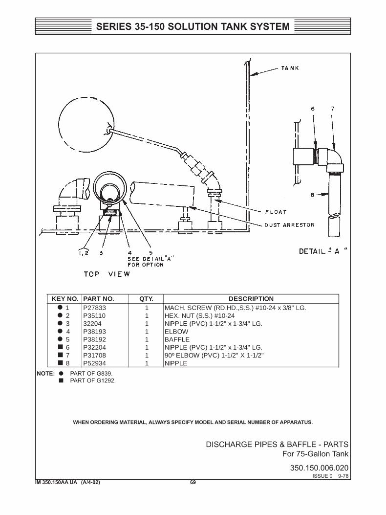
DISCHARGE PIPES & BAFFLE - PARTS For 75-Gallon Tank
350.150.006.020ISSUE 0 9-78
.ONYEK .ONTRAP .YTQ NOITPIRCSED1 33872P 1 .GL"8/3x42-01#).S.S,.DH.DR(WERCS.HCAM2 01153P 1 42-01#).S.S(TUN.XEH3 40223 1 .GL"4/3-1x"2/1-1)CVP(ELPPIN4 39183P 1 WOBLE5 29183P 1 ELFFAB6 40223P 1 .GL"4/3-1x"2/1-1)CVP(ELPPIN7 80713P 1 "2/1-1X"2/1-1)CVP(WOBLEº098 43925P 1 ELPPIN
NOTE: PART OF G839.PART OF G1292.
WHEN ORDERING MATERIAL, ALWAYS SPECIFY MODEL AND SERIAL NUMBER OF APPARATUS.
70IM 350.150AA UA (A/4-02)
SERIES 35-150 SOLUTION TANK SYSTEM
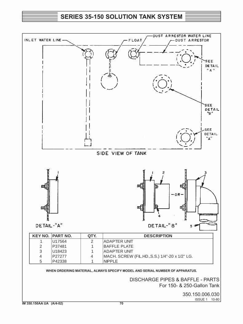
DISCHARGE PIPES & BAFFLE - PARTS For 150- & 250-Gallon Tank
350.150.006.030ISSUE 1 10-80
.ONYEK .ONTRAP .YTQ NOITPIRCSED1 46571U 2 TINURETPADA2 18473P 1 ETALPELFFAB3 32481U 1 TINURETPADA4 77272P 4 .GL"2/1x02-"4/1).S.S,.DH.LIF(WERCS.HCAM5 83324P 1 ELPPIN
WHEN ORDERING MATERIAL, ALWAYS SPECIFY MODEL AND SERIAL NUMBER OF APPARATUS.
71IM 350.150AA UA (A/4-02)
SERIES 35-150 SOLUTION TANK SYSTEM
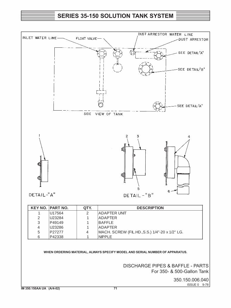
DISCHARGE PIPES & BAFFLE - PARTS For 350- & 500-Gallon Tank
350.150.006.040ISSUE 0 9-78
.ONYEK .ONTRAP .YTQ NOITPIRCSED1 46571U 2 TINURETPADA2 48232U 1 RETPADA3 94194P 1 ELFFAB4 68232U 1 RETPADA5 77272P 4 .GL"2/1x02-"4/1).S.S,.DH.LIF(WERCS.HCAM6 83324P 1 ELPPIN
WHEN ORDERING MATERIAL, ALWAYS SPECIFY MODEL AND SERIAL NUMBER OF APPARATUS.
72IM 350.150AA UA (A/4-02)
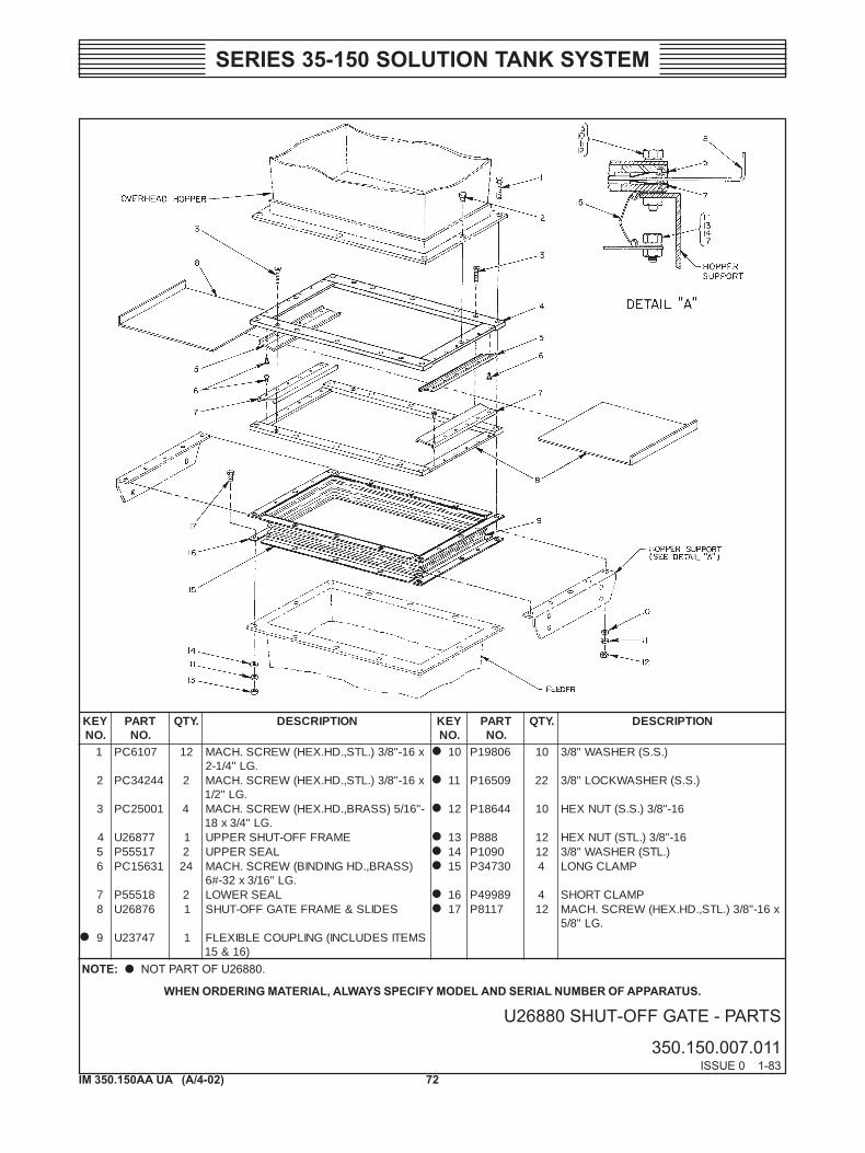
SERIES 35-150 SOLUTION TANK SYSTEM
U26880 SHUT-OFF GATE - PARTS
350.150.007.011ISSUE 0 1-83
YEK.ON
TRAP.ON
.YTQ NOITPIRCSED YEK.ON
TRAP.ON
.YTQ NOITPIRCSED
1 7016CP 21 x61-"8/3).LTS,.DH.XEH(WERCS.HCAM.GL"4/1-2
01 60891P 01 ).S.S(REHSAW"8/3
2 44243CP 2 x61-"8/3).LTS,.DH.XEH(WERCS.HCAM.GL"2/1
11 90561P 22 ).S.S(REHSAWKCOL"8/3
3 10052CP 4 -"61/5)SSARB,.DH.XEH(WERCS.HCAM.GL"4/3x81
21 44681P 01 61-"8/3).S.S(TUNXEH
4 77862U 1 EMARFFFO-TUHSREPPU 31 888P 21 61-"8/3).LTS(TUNXEH5 71555P 2 LAESREPPU 41 0901P 21 ).LTS(REHSAW"8/36 13651CP 42 )SSARB,.DHGNIDNIB(WERCS.HCAM
.GL"61/3x23-#651 03743P 4 PMALCGNOL
7 81555P 2 LAESREWOL 61 98994P 4 PMALCTROHS8 67862U 1 SEDILS&EMARFETAGFFO-TUHS 71 7118P 21 x61-"8/3).LTS,.DH.XEH(WERCS.HCAM
.GL"8/59 74732U 1 SMETISEDULCNI(GNILPUOCELBIXELF
)61&51
WHEN ORDERING MATERIAL, ALWAYS SPECIFY MODEL AND SERIAL NUMBER OF APPARATUS.
NOTE: NOT PART OF U26880.
73IM 350.150AA UA (A/4-02)
SERIES 35-150 SOLUTION TANK SYSTEM
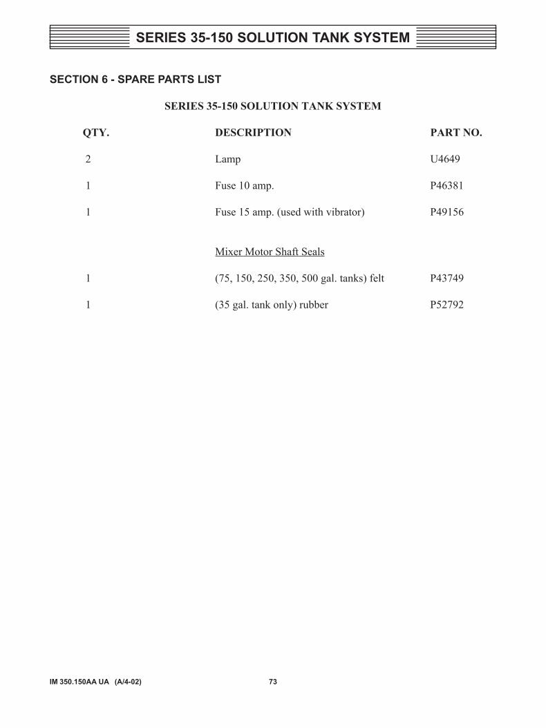
SECTION 6 - SPARE PARTS LIST
SERIES 35-150 SOLUTION TANK SYSTEM
QTY. DESCRIPTION PART NO.
2 Lamp U4649
1 Fuse 10 amp. P46381
1 Fuse 15 amp. (used with vibrator) P49156
Mixer Motor Shaft Seals
1 (75, 150, 250, 350, 500 gal. tanks) felt P43749
1 (35 gal. tank only) rubber P52792

74IM 350.150AA UA (A/4-02)
SERIES 35-150 SOLUTION TANK SYSTEM


![[XLS]dep.ky.govdep.ky.gov/formslibrary/Documents/TankSpreadsheetv6a.xls · Web viewHints Glossary Tank#10 Tank#9 Tank#8 Tank#7 Tank#6 Tank#5 Tank#4 Tank#3 Tank#2 Tank#1 Summary Instructions](https://img.pdfslide.us/doc/110x75/5ab43ede7f8b9a1a048ba1de/xlsdepky-viewhints-glossary-tank10-tank9-tank8-tank7-tank6-tank5-tank4.jpg)