Embed Size (px)
Citation preview
Pro
du
ct
Ca
talo
gu
e
Se
rie
s 3
00
Va
lve
s
Series 3
00 V
alv
es
Cata
logue
Edi
tion
05/2
015
Series 300 Valves

Series 300 Valves
Edition 05/2015
Dorot’s Areas Of Activity
We invite you to join our family of business partners, together we can provide the best control solutions for the world’s most valuable natural resource.
With a diversified product portfolio of advanced hydraulic control valves, air release valves and a wide range of complimentary products, Dorot offers solutions for applications in:
• Agricultural and Landscape Irrigation • Waterworks Distribution • Firefighting • Other Industrial Applications such as Mining, Wastewater, Marine…
Dorot Control Valves is a world leader in the development and supply of sustainable technologies and products for control and optimization of water systems. Established in 1946, Dorot has a long tradition of providing innovative products and solutions for numerous applications in water and other �uid systems.
Our experienced team of technical experts will support you all the way to achieve your perfect control solution.
Series 300 Valves
Edition 05/2015
Contents
General Information 4
Overview 4
Features 4
Engineering Data 5
Technical Specifications 5
Materials 5
Basic Valve Operating Modes 6
Typical Pressure Reducing Performance Chart 10
Cavitation Data 11
Dimensions & Weights - Models 30/31 12
Headloss Charts - Models 30/31 13
Dimensions & Weights - Model 32 14
Headloss Chart - Model 32 15
Components 16
Waterworks Control Application 17
Electronic and Remote control 17
Pressure Regulating 17
Rate of Flow Regulating 17
Water Level Control 18
Pumping Systems Control and Water Hammer / Surge Protection 19
Fire Fighting Applications 20
Pilots and Accessories 21
Other Dorot Products 23
Series 300 Valves
Edition 05/2015
4
General Information
• The capability to regulate near zero flow, as standard on all sizes, eleminates the need for a special low flow (throttling plug) or valve, while ensuring very low head loss in “fully open” position.
• The flange (face-to-face) dimensions suit ISO Standards.
• The valve has an internal floating shaft, allowing for frictionless operation. The unique design of the shaft provides for easy field maintenance.
• The valve has a resilient seal disc, guided by a frictionless centering device.
• The valve’s body is made of Ductile Iron, withstanding both high hydraulic and mechanical stresses.
• The standard single - chamber valve provides smooth operation in sensitive regulation
conditions. When required, conversion from a single to a double chambered valve is easily accomplished through the insertion of Dorot’s innovative separation disc, without the need to remove the valve from the pipeline during the conversion.
• The valve is supplied with a replaceable Stainless Steel seat, which maintains excellent durability against erosion and ensures a drip-tight seal.
• During valve closure the rate slows, preventing potential damage from water hammer or surges.
• The 300 Series includes an optional valve position indicator, attached by a floating connection (ball & socket), resulting in smooth movement, with no wear or tear on the indicator seal.
Features of the 300 Series
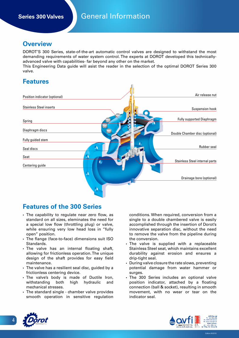
Position indicator (optional)
Stainless Steel inserts
Spring
Diaphragm discs
Fully guided stem
Seal discs
Seat
Centering guide
Air release nut
Suspension hook
Fully supported Diaphragm
Double Chamber disc (optional)
Rubber seal
Stainless Steel internal parts
Drainage bore (optional)
Overview DOROT’S 300 Series, state-of-the-art automatic control valves are designed to withstand the most demanding requirements of water system control. The experts at DOROT developed this technically-advanced valve with capabilities- far beyond any other on the market.This Engineering Data guide will asist the reader in the selection of the optimal DOROT Series 300 valve.
Features

Series 300 Valves
Edition 05/2015
5
Engineering Data
Technical SpecificationsParameter Standard Optional
Connections • Flanged ISO 7005 or ANSI B16• Threaded BSP or NPT
• Flanged AS10, JIS B22, ABNT and others
Pressure range
• Model 30: 0.5 – 16 bar 7 – 250 psi
• Models 31, 32: 0.5 – 25 bar 7 – 360 psi
• 0 min. press. with N.O spring assisted opening.
• 0.2 bar / 3 psi min. pressure without a spring
Note: both options require usage of external higher closing pressure
Max. Water Temperature • 80ºC / 180ºF • 95ºC / 200ºF
MaterialsPart Standard Optional
Body & Cover Ductile Iron GGG50 (ASTM A-536)
Cast Steel A-216 WCBCast Bronze or Marine BronzeCast SST CF8M (316)Ni Aluminum BronzeOthers
Main Valve Internals SST, Bronze and Coated Steel SST 316, HASTELLOY, SMO, DUPLEX
Spring SST 302 SST 316, INCONNEL
Diaphragm Nylon fabric reinforced EPDM (WRAS and NSF approved) NBR
Seals EPDM Viton
Coating Polyester RAL 5010
FBE RAL 5010Polyester RAL3000 (fire red)UV protected FBE RAL3000Rilsan (Nylon)Halar
Control Trim: Fittings and control devices Brass SST 304SST 316
Control Trim: Tubes Reinforced, heavy-duty Nylon, Polypropylene
CopperSST 316
Note: The Dorot S-300 valves in all sizes, meet the USA amendment for reducing lead in drinking water marked as S.3874 dated 01.05.2010.
Series 300 Valves
Edition 05/2015
6
Engineering Data
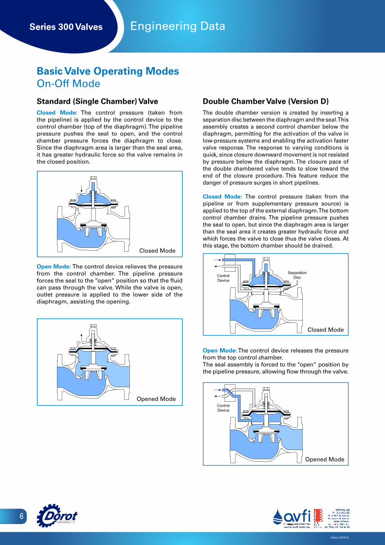
Standard (Single Chamber) ValveClosed Mode: The control pressure (taken from the pipeline) is applied by the control device to the control chamber (top of the diaphragm). The pipeline pressure pushes the seal to open, and the control chamber pressure forces the diaphragm to close. Since the diaphragm area is larger than the seal area, it has greater hydraulic force so the valve remains in the closed position.
Open Mode: The control device relieves the pressure from the control chamber. The pipeline pressure forces the seal to the “open” position so that the fluid can pass through the valve. While the valve is open, outlet pressure is applied to the lower side of the diaphragm, assisting the opening.
Double Chamber Valve (Version D)The double chamber version is created by inserting a separation disc between the diaphragm and the seal. This assembly creates a second control chamber below the diaphragm, permitting for the activation of the valve in low-pressure systems and enabling the activation faster valve response. The response to varying conditions is quick, since closure downward movement is not resisted by pressure below the diaphragm. The closure pace of the double chambered valve tends to slow toward the end of the closure procedure. This feature reduce the danger of pressure surges in short pipelines.
Closed Mode: The control pressure (taken from the pipeline or from supplementary pressure source) is applied to the top of the external diaphragm. The bottom control chamber drains. The pipeline pressure pushes the seal to open, but since the diaphragm area is larger than the seal area it creates greater hydraulic force and which forces the valve to close thus the valve closes. At this stage, the bottom chamber should be drained.
Open Mode: The control device releases the pressure from the top control chamber.The seal assembly is forced to the “open” position by the pipeline pressure, allowing flow through the valve.
Closed Mode
Opened Mode
Closed Mode
Opened Mode
Basic Valve Operating Modes On-Off Mode
Closed Mode
Open Mode
Closed Mode
Open Mode
D chamber - Closed Mode
D chamber - Open Mode
ControlDevice
SeparationDisc
ControlDevice
D chamber - Closed Mode
D chamber - Open Mode
ControlDevice
SeparationDisc
ControlDevice

Series 300 Valves
Edition 05/2015
7
Engineering Data
Modulating ModeGeneralPositioning the seal a short distance (less than 1/4 of the seat diameter) from the seat, creates friction and turbulence, causing energy loss in the fluid passing through the valve. The results are: - Reduction of pressure and flow rate.- Increase of inlet pressure.The position of the seal assembly is dictated by the volume of control fluid in the top control chamber, which is determined by the control device. The control device is operated by hand (manual control), by electric current (solenoid valve), or by hydraulic pressure (pilot valves, hydraulic relays). All can be used in standard (single chamber) valves as well as in double chamber valves.
Modulating mode in standard (single chamber) valves
Regulation at high pressures differenceThe S-300 has exceptional resistance to damages, caused by cavitation conditions. This feature was certified by extensive tests, carried by an independent laboratories in US and Europe. The operation limits, as found in these tests, can be calculated for any specific location- using a simple computer program (supplied on request). For operation conditions that exceed the safe limit- a special Cavitation-Free valve can be supplied. This version, marked by the suffix “F” (example 30F-3 is a cavitation-free, 80mm / 3” valve), can operate at any pressure differential without being ruined by it. The internal structure includes a Stainless Steel, perforated cylinder, that is connected below the standard seal disc and moving freely inside the seat. The valve is assembled to generate “over the seat” flow, so the water stream enters the cylinder from its external side and emerges through the internal side. The energy is dissipated by the high-velocity, turbulent flow through the exposed holes above the seat (due to varying trim position). The pressure recovery, that is the cause of cavitation damage, happens now inside the cylinder and not adjacent to the body wall. As the SST material is highly- resistant to cavitation- it is not damaged.
Pg .G3-b 3/3/02 11:38 Page 1
Composite
C M Y CM MY CY CMY K
Fully Open
Power-Opening ModeDouble Chamber ValveThis operating mode is selected when the control pressureis taken from an external source ( a water system withhigher pressure, compressed air, etc...) rather than fromthe pipeline. This mode is usually selected when pipelinepressure is extremely low. The control system is able topressurize one chamber while simultaneously draining theother one.
Closed Mode: The control device applies pressure tothe top chamber while draining the bottom chamber. Thediaphragm is forced down, causing the seal to close thewater passage.
2002G3-b
Open Mode: The control device releases the pressurefrom the top control chamber and applies pressure to thebottom control chamber. The seal assembly is forced to the"open" position, allowing flow through the valve.
Closed Mode
SeparationDisc
Open Mode
ControlDevice
ControlDevice
Closed
Regulating
Modulating Mode
GeneralPositioning the seal a short distance (less than 1/4 of theseat diameter) from the seat, creates friction and turbulence,causing energy loss in the fluid passing through the valve.The results are:-Reduction of pressure and flow rate.-Increase of inlet pressure.The position of the seal assembly is dictated by the volumeof control fluid in the top control chamber which is determinedby the control device.The control device is operated by hand (manual control), byelectric current (solenoid valve), or by hydraulic pressure(pilot valves, hydraulic relays). All can be used in standard(single chamber) valves as well as in double chamber valves.
Modulating mode in standard (single chamber) valves.
Closed
Fully Open
Regulating
Closed Valve
Fully-opened Valve
Cavitation energy dissipation area

Series 300 Valves
Edition 05/2015
8
Engineering Data
2-Way Control DeviceThe 2-way control device is assembled on a control circuit, connecting upstream to downstream through the control chamber.There are two restrictors assembled in this circuit:(a) A nozzle or a needle valve, at a fixed opening.(b) A modulating device (pilot), whose passage may vary from complete closure (b=o) to a fully open size (when b>a).The volume of the control media in the chamber is determined by the relative passages (a) and (b), or, in fact, by the opening of (b), as (a) is fixed.
Closed Mode: Pilot (b) senses a downstream pressure higher than the set-point and closes passage (b). Through passage (a) the upstream water flows directly into the upper part of the control chamber, forcing the diaphragm to close the valve.
Open Mode: Pilot (b) senses a downstream pressure lower than the set-point, and fully opens passage (b), larger than (a). All the water from the upstream flows through (a) and (b), directly to the downstream, allowing water from the upper part of the control chamber to partially drain until the pressure in the chamber equals the downstream pressure.Pressure in the upper part of the control chamber is decreased and the upstream water pressure forces the seal disc to rise (opening the valve).
Regulating Mode: The pilot is set to the required downstream pressure. The pilot senses when the downstream pressure reaches the required value causing passage (b) to equal passage (a) b=a. Now, water that flows through the control loop passes from (a) through (b) and into the downstream. The control media in the upper part of the control chamber is now steady, keeping the diaphragm and seal in a fixed position. Any change in the downstream pressure will change the b=a balance. This change adds or drains water from the control chamber, thus opening or closing the main valve until it reaches the balanced regulating position b=a once again.
The 2-way control device provides sensitive, accurate, and constant modulating, control of the main valve. The main valve does not fully open, as the control device prevents total draining of the control chamber.The 2-way control device is standard in most pressureregulating valves.
Closed Valve
Opened Valve
Closed Valve
Regulating Valve
Regulating Valve
Closed Mode
Open Mode
Closed Mode
Open Mode

Series 300 Valves
Edition 05/2015
9
Engineering Data
3-Way Control DeviceThe 3-way control device is a small selector valve which:1. Permits passage of the control media into the
main valve control chamber (initiating the “closing” procedure), or
2. Permits drainage of the control media from the control chamber to the atmosphere (initiating the “opening” procedure).
Some of the 3-way control devices have a third mode as well, which prevents inflow or outflow from the control chamber, so that the main valve remains fixed when the device is in this mode.The 3-way mode is used in on-off valves or when the regulating valve is fully open, in order to obtain specific operating conditions. Once in position, there is no water flow through the control chamber.The 3-way control circuit may open the main valve entirely, creating minimum head loss.The 3-way control device must be used when external media (not pipeline water) is used to control the valve, or when the control media is dirty or abrasive.
Proportional Pressure ReducerThe proportional pressure reducer is a valve that has a control chamber permanently connected to the downstream.This valve must be a double chamber [D] type.The balance of hydraulic forces created between the high pressure on the small seal area, and the lower downstream pressure on the larger diaphragm area, causes a fixed ratio of inlet/outlet pressure of approximately 3:1.No other control device is needed.
Closed Valve
Opened Valve
Pg .G3-d 3/3/02 11:50 Page 1
Composite
C M Y CM MY CY CMY K
2002G3-d
Non-Return (Check Valve) ModeDouble Chamber ValveFlow in the normal direction forces the seal to the "open"position, allowing for free flow. When downstream pressureexceeds upstream pressure, return flow may occur, causingthe seal disc to instantly close as a result of both hydraulicforce and the spring's force.
Proportional Pressure ReducerThe proportional pressure reducer is a valve that has a controlchamber permanently connected to the downstream.This valve must be a double chamber [D] type.The balance of hydraulic forces created between the highpressure on the small seal area, and the lower downstreampressure on the larger diaphragm area, causes a fixed ratioof inlet/outlet pressure of approximately 3:1.
No other control device is needed.
Regular Flow
Return Flow
Closed Valve
Open Valve
3-Way Control DeviceThe 3-way control device is a small selector valve which:1.Permits passage of the control media into the main valvecontrol chamber (initiating the "closing" procedure),or2. Permits drainage of the control media from the controlchamber to the atmosphere (initiating the "opening" procedure).
Some of the 3-way control devices have a third mode aswell, which prevents inflow or outflow from the controlchamber, so that the main valve remains fixed when thedevice is in this mode.This mode is used in on-off valves or when the regulatingvalve is fully open, in order to obtain specific operatingconditions. Once in position, there is no water flow throughthe control chamber.The 3-way control device may open the main valve entirely,creating minimum head loss.The 3-way control device must be used when external media(not pipeline water) is used to control the valve, or whenthe control media is abrasive.
Separation Disc
Closed Mode
Open Mode
Closed Mode
Open Mode
Series 300 Valves
10
Edition 05/2015
0
10
20
30
40
50
60
70
80
90
100
0 0.1 0.2 0.3 0.4 0.5 0.6 0.7KnKv
SERIES 300 CHARACTERISTIC CURVECOMPARISON WITH COMPETITIVE DESIGNS
*
10
20
30
40
50
60
70
80
0
1
2
3
4
5
6
7
8
9
0
Day 1 Day 2 Day 3 Day 4 Day 5 Day 6 Day 7 Day 8
0.8 0.9 1.0
Engineering Data
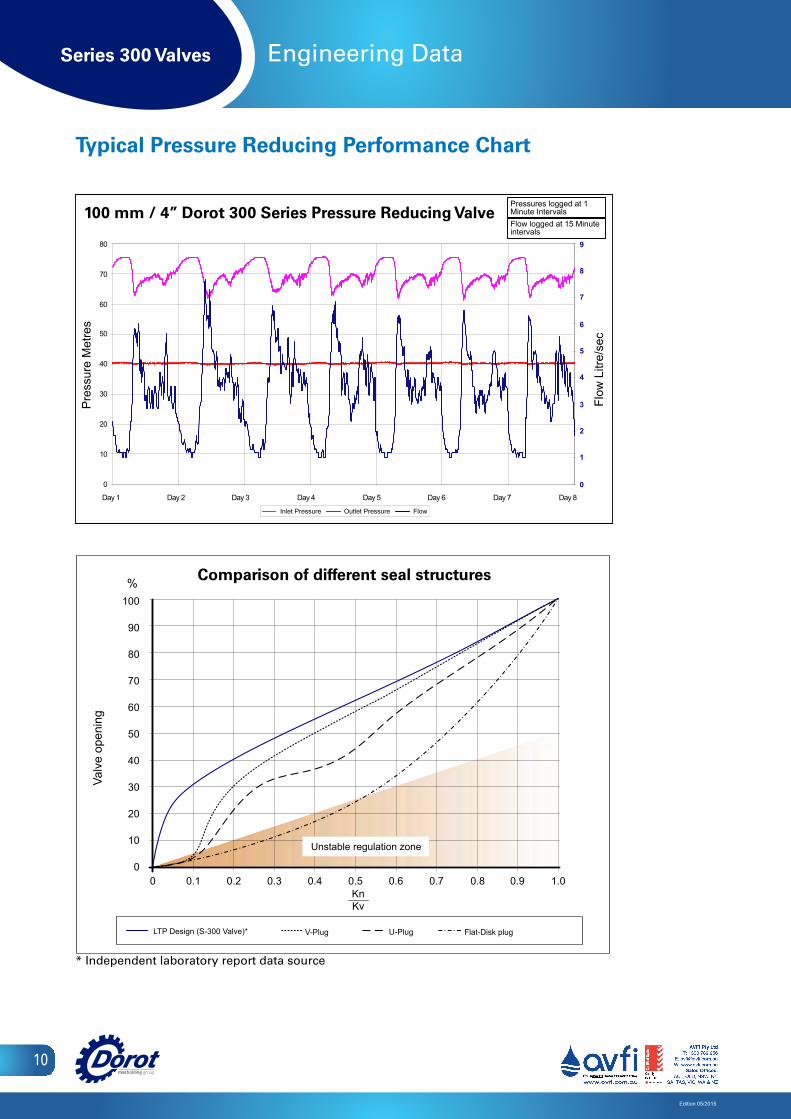
Typical Pressure Reducing Performance Chart
Valv
e op
enin
g
Comparison of different seal structures
100 mm / 4” Dorot 300 Series Pressure Reducing Valve
Flat-Disk plug
%
U-PlugV-PlugLTP Design (S-300 Valve)*
Unstable regulation zone
Pre
ssur
e M
etre
s
Outlet Pressure
Flow
Litr
e/se
c
* Independent laboratory report data source
Pressures logged at 1 Minute IntervalsFlow logged at 15 Minute intervals
FlowInlet Pressure

Series 300 Valves
Edition 05/2015
11
Engineering Data
Cavitation Data
10 20 30 40 50 60 70 80 mwc
Outlet pressure
10 30 50 60 70 90 100 110 psi 80 40 20
0
10
20
30
40
50
60
70
80
90
100
110
120
130
140
150
160
170
180
190
200
210
220
230
240
250
20
40
60
80
100
120
140
160
180
200
220
240
260
280
300
320
340
360 mwc psi
Inlet pressure
Case- III
Case- II
Case- I
Destructive Cavitation
Noisy Operating
Safe Operating conditions
Cavitation Chart Limits of operating conditionsThe chart above sets the safe limits for valves that are supposed to operate at a considerable pressure differential.Such conditions generate noise and possible cavitation damages to the valve body.How to use the chart:i. Determine the maximal dynamic pressure that may be applied in the inlet of the valve.ii. Draw an horizontal line from the pressure scale at the left side of the chartiii. Find the requested outlet pressure in the pressure scale at the bottom of the chart.iv. Draw an upward line at this point.v. The intersection of the two lines defines the cavitation characteristics of the valve operation.
- In the case that it falls in the RED zone (case I)- the valve may be damaged in a fairly short time.- In the case that it falls in the YELLOW zone (case II)- the valve may generate a noise that exceeds 80db.- In the case that the intersection is within the GREEN zone (case III)- the valve will perform safely and quietly
General remark: The cavitation and noise data are based on tests done by the Utah State University, US, and Delft Hydraulic Laboratories, Holland.
Inlet pressure
Outlet pressure
Destructive Cavitation
NoisyOperating
Case 1
Case 2
Case 3
Safe OperatingConditions
Series 300 Valves
Edition 05/2015
12
Engineering Data
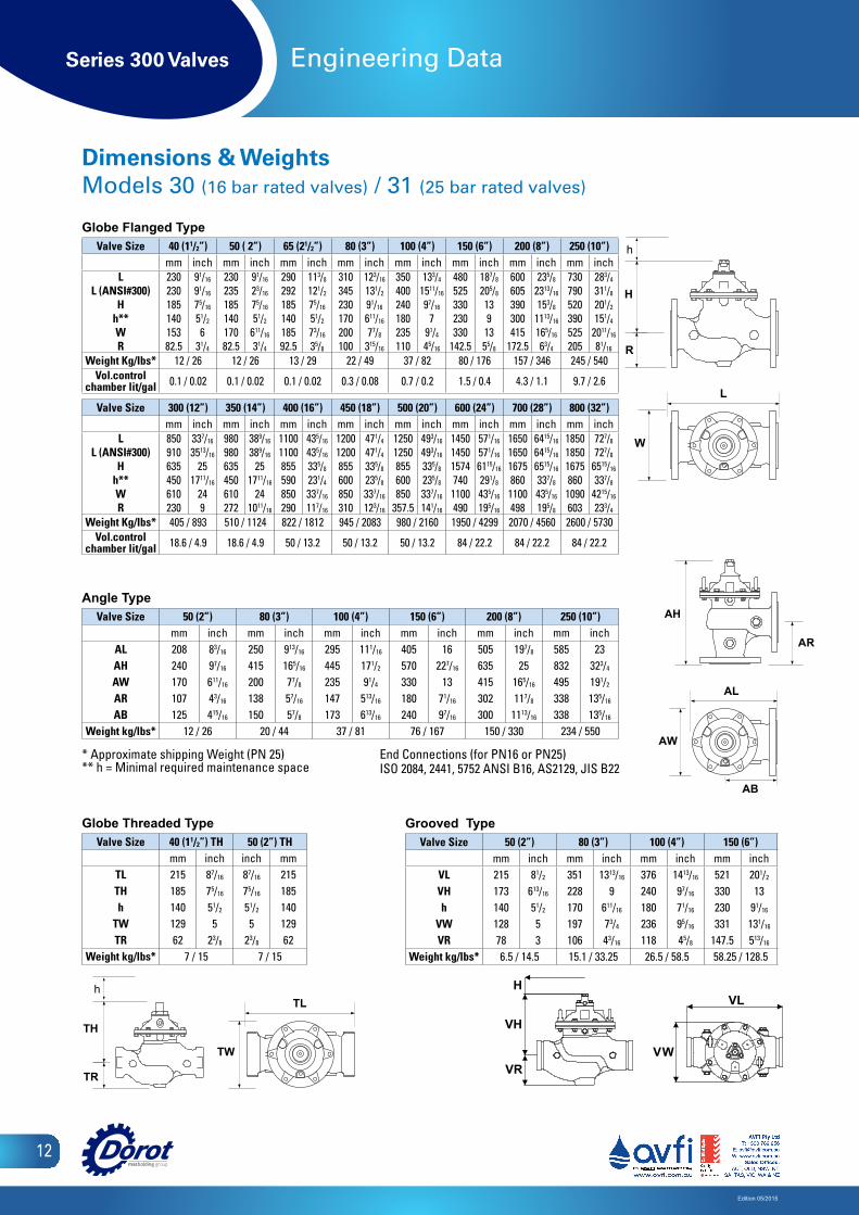
Dimensions & WeightsModels 30 (16 bar rated valves) / 31 (25 bar rated valves)
H
L
W
AH
AR
AL
TH
TR
TL
R
TW
AB
h h
AW
H
L
W
AH
AR
AL
TH
TR
TL
R
TW
AB
h h
AW
Globe Flanged Type Valve Size 40 (11/2”) 50 ( 2”) 65 (21/2”) 80 (3”) 100 (4”) 150 (6”) 200 (8”) 250 (10”)
mm inch mm inch mm inch mm inch mm inch mm inch mm inch mm inchL
L (ANSI#300)H
h**WR
23023018514015382.5
91/16
91/16
75/16
51/2
631/4
23023518514017082.5
91/16
23/16
75/16
51/2
611/16
31/4
29029218514018592.5
113/8
121/2
75/16
51/2
73/16
35/8
310345230170200100
123/16
131/2
91/16
611/16
77/8
315/16
350400240180235110
133/4
1511/16
97/16
791/4
45/16
480525330230330
142.5
187/8
205/8
1391355/8
600605390300415
172.5
235/8
2313/16
153/8
1113/16
165/16
63/4
730790520390525205
283/4
311/8
201/2
151/4
2011/16
81/16
Weight Kg/Ibs* 12 / 26 12 / 26 13 / 29 22 / 49 37 / 82 80 / 176 157 / 346 245 / 540Vol.control
chamber lit/gal 0.1 / 0.02 0.1 / 0.02 0.1 / 0.02 0.3 / 0.08 0.7 / 0.2 1.5 / 0.4 4.3 / 1.1 9.7 / 2.6
Valve Size 300 (12”) 350 (14”) 400 (16”) 450 (18”) 500 (20”) 600 (24”) 700 (28”) 800 (32”)mm inch mm inch mm inch mm inch mm inch mm inch mm inch mm inch
LL (ANSI#300)
Hh**WR
850910635450610230
337/16
3513/16
251711/16
249
980980635450610272
389/16
389/16
251711/16
241011/16
11001100855590850290
435/16
435/16
335/8
231/4
337/16
117/16
12001200855600850310
471/4
471/4
335/8
235/8
337/16
123/16
12501250855600850
357.5
493/16
493/16
335/8
235/8
337/16
141/16
1450145015747401100490
571/16
571/16
6115/16
291/8
435/16
195/16
1650165016758601100498
6415/16
6415/16
6515/16
337/8
435/16
195/8
1850185016758601090603
727/8
727/8
6515/16
337/8
4215/16
233/4
Weight Kg/Ibs* 405 / 893 510 / 1124 822 / 1812 945 / 2083 980 / 2160 1950 / 4299 2070 / 4560 2600 / 5730Vol.control
chamber lit/gal 18.6 / 4.9 18.6 / 4.9 50 / 13.2 50 / 13.2 50 / 13.2 84 / 22.2 84 / 22.2 84 / 22.2
Globe Threaded TypeValve Size 40 (11/2”) TH 50 (2”) TH
mm inch inch mmTL 215 87/16 87/16 215TH 185 75/16 75/16 185h 140 51/2 51/2 140
TW 129 5 5 129TR 62 23/8 23/8 62
Weight kg/lbs* 7 / 15 7 / 15
* Approximate shipping Weight (PN 25) ** h = Minimal required maintenance space
End Connections (for PN16 or PN25)ISO 2084, 2441, 5752 ANSI B16, AS2129, JIS B22
H
L
W
AH
AR
AL
TH
TR
TL
R
TW
AB
h h
AW
H
L
W
AH
AR
AL
TH
TR
TL
R
TW
AB
h h
AW
Angle TypeValve Size 50 (2”) 80 (3”) 100 (4”) 150 (6”) 200 (8”) 250 (10”)
mm inch mm inch mm inch mm inch mm inch mm inchAL 208 83/16 250 913/16 295 111/16 405 16 505 197/8 585 23AH 240 97/16 415 165/16 445 171/2 570 227/16 635 25 832 323/4
AW 170 611/16 200 77/8 235 91/4 330 13 415 165/16 495 191/2
AR 107 43/16 138 57/16 147 513/16 180 71/16 302 117/8 338 135/16
AB 125 415/16 150 57/8 173 613/16 240 97/16 300 1113/16 338 135/16
Weight kg/lbs* 12 / 26 20 / 44 37 / 81 76 / 167 150 / 330 234 / 550
H
L
W
AH
AR
AL
TH
TR
TL
R
TW
AB
h h
AW
H
L
W
AH
AR
AL
TH
TR
TL
R
TW
AB
h h
AW
Grooved TypeValve Size 50 (2”) 80 (3”) 100 (4”) 150 (6”)
mm inch mm inch mm inch mm inchVL 215 81/2 351 1313/16 376 1413/16 521 201/2
VH 173 613/16 228 9 240 97/16 330 13 h 140 51/2 170 611/16 180 71/16 230 91/16
VW 128 5 197 73/4 236 95/16 331 131/16
VR 78 3 106 43/16 118 45/8 147.5 513/16
Weight kg/lbs* 6.5 / 14.5 15.1 / 33.25 26.5 / 58.5 58.25 / 128.5VH
H
VRVH
H
VRVW
VL
VW
VL
Series 300 Valves
Edition 05/2015
13
Engineering Data
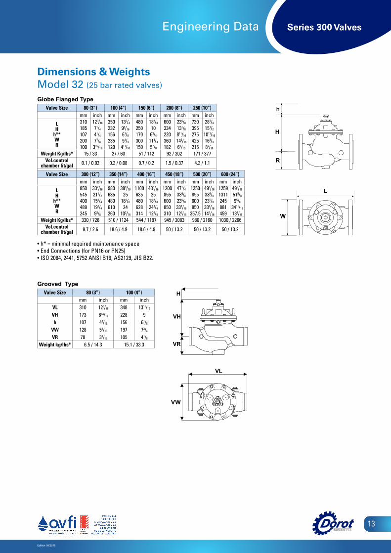
Dimensions & WeightsModel 32 (25 bar rated valves)
Globe Flanged TypeValve Size 80 (3”) 100 (4”) 150 (6”) 200 (8”) 250 (10”)
mm inch mm inch mm inch mm inch mm inch
LH
h**WR
310185107200100
123/16
71/4
41/4
77/8
315/16
350232156235120
133/4
93/16
61/8
91/4
411/16
480250170300150
187/8
10 63/4
113/4
57/8
600334220360182
235/8
131/8
811/16
143/16
63/16
730395275425215
283/4
151/2
1013/16
163/4
87/16
Weight Kg/Ibs* 15 / 33 27 / 60 51 / 112 92 / 202 171 / 377Vol.control
chamber lit/gal 0.1 / 0.02 0.3 / 0.08 0.7 / 0.2 1.5 / 0.37 4.3 / 1.1
Valve Size 300 (12”) 350 (14”) 400 (16”) 450 (18”) 500 (20”) 600 (24”)mm inch mm inch mm inch mm inch mm inch mm inch
LH
h**WR
850545400489245
337/16
211/2
153/4
191/4
93/8
980635480610260
389/16
25187/8
24103/16
1100635480628314
435/16
25187/8
243/4
123/8
1200855600850310
471/4
335/8
235/8
337/16
123/16
1250855600850
357.5
493/16
335/8
235/8
337/16
141/16
12591311245881459
499/16
515/8
95/8
3411/16
181/16
Weight Kg/Ibs* 330 / 726 510 / 1124 544 / 1197 945 / 2083 980 / 2160 1030 / 2266Vol.control
chamber lit/gal 9.7 / 2.6 18.6 / 4.9 18.6 / 4.9 50 / 13.2 50 / 13.2 50 / 13.2
• h* = minimal required maintenance space• End Connections (for PN16 or PN25) • ISO 2084, 2441, 5752 ANSI B16, AS2129, JIS B22.
Grooved TypeValve Size 80 (3”) 100 (4”)
mm inch mm inchVL 310 123/16 348 1311/16
VH 173 613/16 228 9 h 107 43/16 156 61/8
VW 128 51/16 197 73/4
VR 78 31/16 105 41/8
Weight kg/lbs* 6.5 / 14.3 15.1 / 33.3
H
L
W
AH
AR
AL
TH
TR
TL
R
TW
AB
h h
AW
H
L
W
AH
AR
AL
TH
TR
TL
R
TW
AB
h h
AW
VH
H
VRVH
H
VRVW
VL
VW
VL
Series 300 Valves
Edition 05/2015
14
Engineering Data
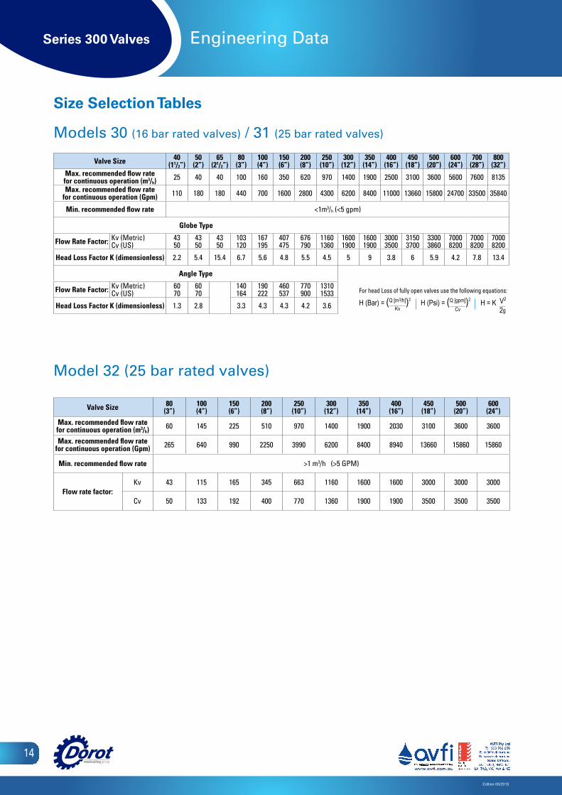
Model 32 (25 bar rated valves)
Valve Size 80(3”)
100(4”)
150(6”)
200(8”)
250(10”)
300(12”)
350(14”)
400(16”)
450(18”)
500(20”)
600(24”)
Max. recommended flow rate for continuous operation (m3/h) 60 145 225 510 970 1400 1900 2030 3100 3600 3600
Max. recommended flow rate for continuous operation (Gpm) 265 640 990 2250 3990 6200 8400 8940 13660 15860 15860
Min. recommended flow rate >1 m3/h (>5 GPM)
Flow rate factor:Kv 43 115 165 345 663 1160 1600 1600 3000 3000 3000
Cv 50 133 192 400 770 1360 1900 1900 3500 3500 3500
Size Selection Tables
Models 30 (16 bar rated valves) / 31 (25 bar rated valves)
Valve Size 40 (11/2”)
50 (2”)
65 (21/2”)
80 (3”)
100 (4”)
150 (6”)
200 (8”)
250 (10”)
300 (12”)
350 (14”)
400 (16”)
450 (18”)
500 (20”)
600 (24”)
700 (28”)
800 (32”)
Max. recommended flow rate for continuous operation (m3/h) 25 40 40 100 160 350 620 970 1400 1900 2500 3100 3600 5600 7600 8135
Max. recommended flow rate for continuous operation (Gpm) 110 180 180 440 700 1600 2800 4300 6200 8400 11000 13660 15800 24700 33500 35840
Min. recommended flow rate <1m3/h (<5 gpm)
Globe Type
Flow Rate Factor: Kv (Metric)Cv (US)
4350
4350
4350
103120
167195
407475
676790
11601360
16001900
16001900
30003500
31503700
33003860
70008200
70008200
70008200
Head Loss Factor K (dimensionless) 2.2 5.4 15.4 6.7 5.6 4.8 5.5 4.5 5 9 3.8 6 5.9 4.2 7.8 13.4
Angle Type
Flow Rate Factor: Kv (Metric)Cv (US)
6070
6070
140164
190222
460537
770900
13101533
Head Loss Factor K (dimensionless) 1.3 2.8 3.3 4.3 4.3 4.2 3.6
For head Loss of fully open valves use the following equations:
H (Bar) = (Q [m3/h])2 H (Psi) = (Q [gpm])2 H = K V2 Kv Cv 2g
Series 300 Valves
Edition 05/2015
15
Engineering Data
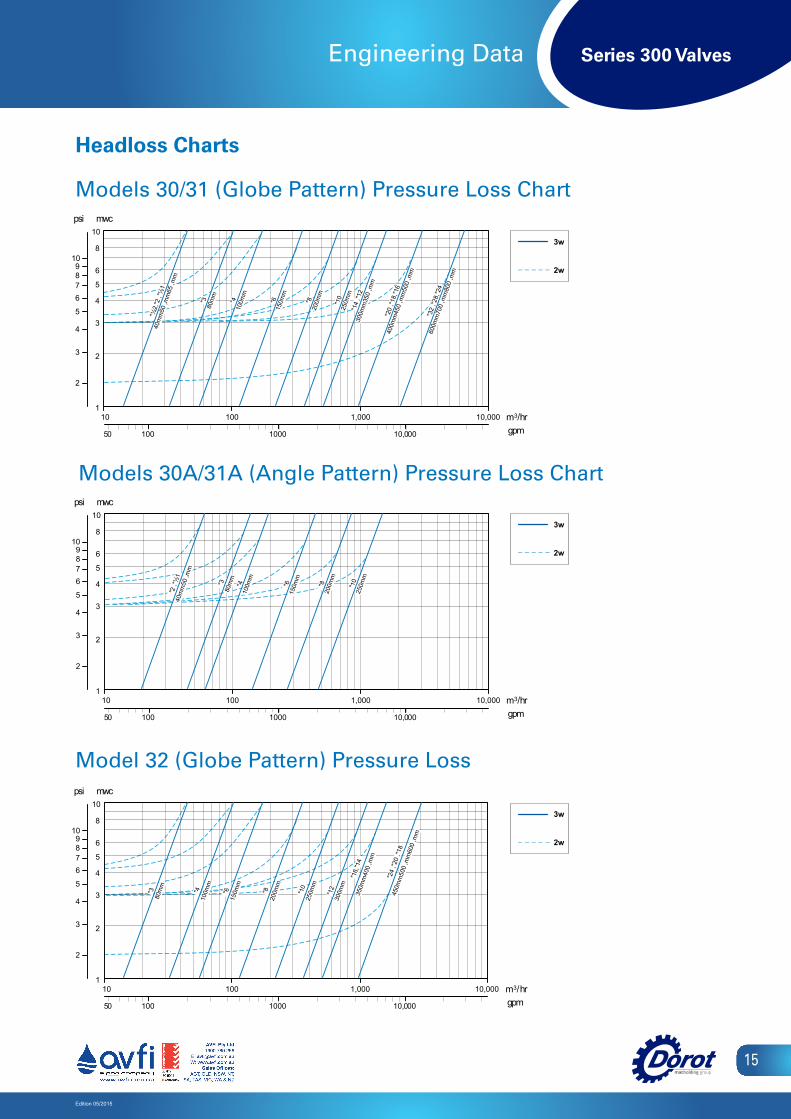
Headloss Charts
100 1000 10,000 gpm50
3w 2w
1
10
10 1,000
2
3
4
5
6
8
100 10,000 m3/hr
mwc
2
3
4
5
678
109
psi
3"80
mm 4"
100m
m
6"15
0mm
8"20
0mm
10"25
0mm
18", 20",
24"45
0mm
, 50
0m
m,
600
mm
MODEL 32 (GLOBE PATTERN) PRESSURE LOSS CHART
12"30
0mm
14",16"
350m
m,
400
mm
w 3 w 2
1
0 1
0 0 0 , 1 0 1
2
3
4
5
6
8
0 0 1
001
0 0 0 , 0 1 m 3 r h / m p g
c w m
2
3
4
5 6 7 8
0 1 9
i s p
3 "
8 0 m
m
4 "
1 0 0 m
m
6 "
1 5 0 m
m
8 "
2 0 0 m
m
1 0 "
2 5 0 m
m 1 8
" , 2 0
" , 2 4
" 4 5
0 m m
, 5 0 0
m m
, 6 0 0
m m
T R A H C S S O L E R U S S E R P ) N R E T T A P E B O L G ( 2 3 L E D O M
1 2 "
3 0 0 m
m 1 4
" , 1 6 "
3 5
0 m m
, 4 0 0
m m
000,1 000,01
Model 32 (Globe Pattern) Pressure Loss
Models 30/31 (Globe Pattern) Pressure Loss Chart
Models 30A/31A (Angle Pattern) Pressure Loss Chart
w 3 w 2
1
0 1
0 0 0 , 1 0 1
2
3
4
5
6
8
0 0 1
001
0 0 0 , 0 1 m 3 r h / m p g
c w m
2
3
4
5 6 7 8
0 1 9
i s p
3 "
8 0 m
m
4 "
1 0 0 m
m
6 "
1 5 0 m
m
8 "
2 0 0 m
m
1 0 "
2 5 0 m
m 1 8
" , 2 0
" , 2 4
" 4 5
0 m m
, 5 0 0
m m
, 6 0 0
m m
T R A H C S S O L E R U S S E R P ) N R E T T A P E B O L G ( 2 3 L E D O M
1 2 "
3 0 0 m
m 1 4
" , 1 6 "
3 5
0 m m
, 4 0 0
m m
000,1 000,01
100 1000 10,000 gpm50
1
10
10 1,000
2
3
4
5
6
8
100 10,000 m3/hr
mwc
2
3
4
5
678
109
psi
1½", 2",2
½"40
mm
, 50
mm
, 65
mm
3"80
mm 4"
100m
m
6"15
0mm
8"20
0mm
10"25
0mm 12",
14"30
0mm
, 35
0m
m
16",18",
20"40
0mm
, 45
0m
m,
500
mm
24",28",
32"60
0mm
, 70
0m
m,
800
mm
MODELS 30 \ 31 (GLOBE PATTERN) PRESSURE LOSS CHART
3w 2w
1
10
10 1,000
2
3
4
5
6
8
100 10,000 m3/hr
mwc
2
3
4
5
678
109
psi
1½", 2"
40m
m,
50m
m
3"80
mm 4"
100m
m
6"15
0mm
8"20
0mm
MODELS 30A \ 31A (ANGLE PATTERN) PRESSURE LOSS CHART
10"25
0mm
3w 2w
100 1000 10,000 gpm50
w 3 w 2
1
0 1
0 0 0 , 1 0 1
2
3
4
5
6
8
0 0 1
001
0 0 0 , 0 1 m 3 r h / m p g
c w m
2
3
4
5 6 7 8
0 1 9
i s p
3 "
8 0 m
m
4 "
1 0 0 m
m
6 "
1 5 0 m
m
8 "
2 0 0 m
m
1 0 "
2 5 0 m
m 1 8
" , 2 0
" , 2 4
" 4 5
0 m m
, 5 0 0
m m
, 6 0 0
m m
T R A H C S S O L E R U S S E R P ) N R E T T A P E B O L G ( 2 3 L E D O M
1 2 "
3 0 0 m
m 1 4
" , 1 6 "
3 5
0 m m
, 4 0 0
m m
000,1 000,01

Series 300 Valves
Edition 05/2015
16
Engineering Data
Components
DiaphragmAssembly
Bonnet Assembly
Body Assembly
Bolts & NutsLifting Ring
Spring
Position Ind. Kit
Double-ChamberConversion Kit
‘F’ VersionConversion Kit
Series 300 Valves
Edition 05/2015
17
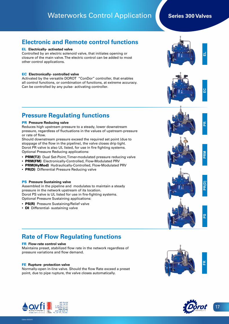
Waterworks Control Application
Electronic and Remote control functions EL Electrically- activated valve Controlled by an electric solenoid valve, that initiates opening or closure of the main valve. The electric control can be added to most other control applications.
EC Electronically- controlled valveActivated by the versatile DOROT “ConDor” controller, that enables all control functions, or combination of functions, at extreme accuracy. Can be controlled by any pulse- activating controller.
Pressure Regulating functions PR Pressure Reducing valve Reduces high upstream pressure to a steady, lower downstream pressure, regardless of fluctuations in the values of upstream-pressure or rate of flow. Should downstream pressure exceed the required set point (due to stoppage of the flow in the pipeline), the valve closes drip tight. Dorot PR valve is also UL listed, for use in fire fighting systems. Optional Pressure Reducing applications:
• PRM(T2) Dual Set-Point, Timer-modulated pressure reducing valve • PRM(FM) Electronically-Controlled, Flow-Modulated PRV• PRM(HyMod) Hydraulically-Controlled, Flow-Modulated PRV• PR(D) Differential Pressure Reducing valve
PS Pressure Sustaining valveAssembled in the pipeline and modulates to maintain a steady pressure in the network upstream of its location.Dorot PS valve is UL listed for use in fire-fighting systems. Optional Pressure Sustaining applications:
• PS(R) Pressure Sustaining/Relief valve • DI Differential- sustaining valve
Rate of Flow Regulating functions FR Flow-rate control valve Maintains preset, stabilized flow rate in the network regardless of pressure variations and flow demand.
FE Rupture- protection valve Normally-open in-line valve. Should the flow Rate exceed a preset point, due to pipe rupture, the valve closes automatically.
ELPR
PSFR
ECPR
MPR
(D)

Series 300 Valves
Edition 05/2015
18
Waterworks Control Application
Water Level Control
FL Water-level control valve- modulating type Mounted on the tank / reservoir inlet, below or above the water level. Closes when the water level rises to the float location, preventing overflow, and opens when the water level drops.
FLDI1 and FLDI2 Water-level control valve- differential type Mounted on the tank / reservoir inlet, below or above the water level.It closes when the water rises to the requested maximal level, and opens when the water level drops to a preset minimal point. The levels difference is adjustable.
AL Altitude control valve Mounted on the inlet of the tank / reservoir, below the water level .The valve is activated by the hydrostatic pressure of the water level. It closes when the water rise to the requested maximal level, and opens fully when the water level drops to the preset minimal point. The differential between the water levels is adjustable.
FLEL Electrically-activated level control valveMounted on the tank / reservoir inlet, below or above the requested water level.Activated by An Electric Float pilot located in the tank / reservoir. It closes when the water rise to the requested maximal level, and opens fully when the water level drops to the preset minimal point. The differential between the water levels is adjustable.
AL / PR, FLDI1 / PR, FLDI2 / PR Combination of water level and flow rate controlMounted on the tank / reservoir inlet. It limits the flow into the tank, and maintain the preset maximal and minimal water levels.
AL / PS, FLDI1 / PS, FLDI2 / PS Combination of water level and back-pressure controlMounted on the tank / reservoir inlet. It maintains the pressure in the supply network and the preset maximal and minimal water levels.
FLFL
DI
AL
FLEL
Series 300 Valves
Edition 05/2015
19
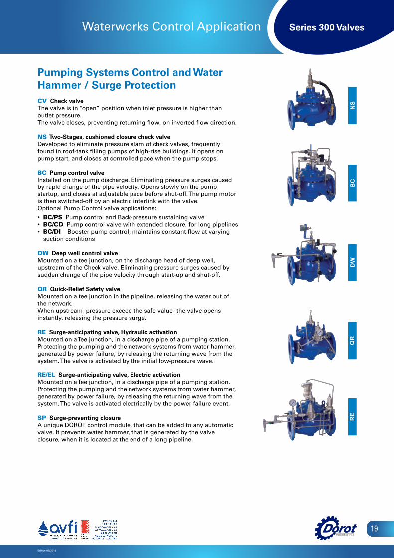
Waterworks Control Application
Pumping Systems Control and Water Hammer / Surge Protection CV Check valve The valve is in “open” position when inlet pressure is higher than outlet pressure.The valve closes, preventing returning flow, on inverted flow direction.
NS Two-Stages, cushioned closure check valveDeveloped to eliminate pressure slam of check valves, frequently found in roof-tank filling pumps of high-rise buildings. It opens on pump start, and closes at controlled pace when the pump stops.
BC Pump control valveInstalled on the pump discharge. Eliminating pressure surges caused by rapid change of the pipe velocity. Opens slowly on the pump startup, and closes at adjustable pace before shut-off. The pump motor is then switched-off by an electric interlink with the valve.Optional Pump Control valve applications:
• BC/PS Pump control and Back-pressure sustaining valve• BC/CD Pump control valve with extended closure, for long pipelines• BC/DI Booster pump control, maintains constant flow at varying
suction conditions
DW Deep well control valveMounted on a tee junction, on the discharge head of deep well, upstream of the Check valve. Eliminating pressure surges caused by sudden change of the pipe velocity through start-up and shut-off.
QR Quick-Relief Safety valveMounted on a tee junction in the pipeline, releasing the water out of the network.When upstream pressure exceed the safe value- the valve opens instantly, releasing the pressure surge.
RE Surge-anticipating valve, Hydraulic activationMounted on a Tee junction, in a discharge pipe of a pumping station. Protecting the pumping and the network systems from water hammer, generated by power failure, by releasing the returning wave from the system. The valve is activated by the initial low-pressure wave.
RE/EL Surge-anticipating valve, Electric activationMounted on a Tee junction, in a discharge pipe of a pumping station. Protecting the pumping and the network systems from water hammer, generated by power failure, by releasing the returning wave from the system. The valve is activated electrically by the power failure event.
SP Surge-preventing closureA unique DOROT control module, that can be added to any automatic valve. It prevents water hammer, that is generated by the valve closure, when it is located at the end of a long pipeline.
QR
DW
BC
RE
NS
Series 300 Valves
Edition 05/2015
20
Fire Fighting Applications
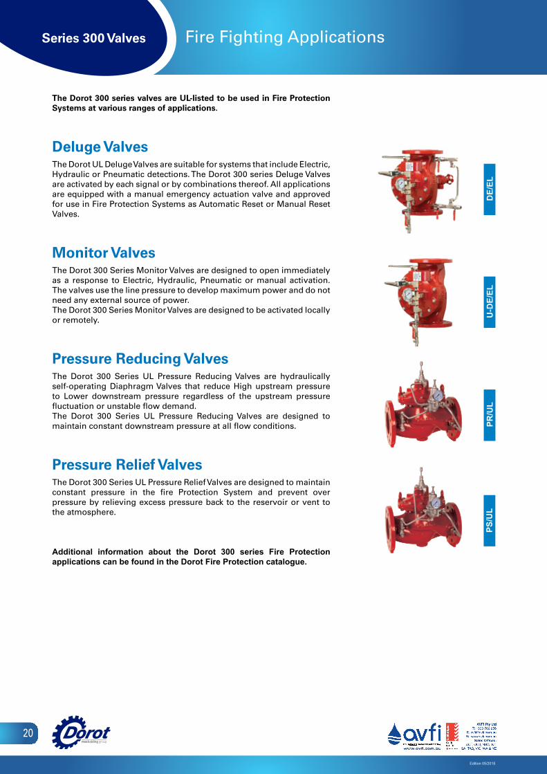
The Dorot 300 series valves are UL-listed to be used in Fire Protection Systems at various ranges of applications.
Deluge Valves The Dorot UL Deluge Valves are suitable for systems that include Electric, Hydraulic or Pneumatic detections. The Dorot 300 series Deluge Valves are activated by each signal or by combinations thereof. All applications are equipped with a manual emergency actuation valve and approved for use in Fire Protection Systems as Automatic Reset or Manual Reset Valves.
Monitor Valves The Dorot 300 Series Monitor Valves are designed to open immediately as a response to Electric, Hydraulic, Pneumatic or manual activation. The valves use the line pressure to develop maximum power and do not need any external source of power. The Dorot 300 Series Monitor Valves are designed to be activated locally or remotely.
Pressure Reducing Valves The Dorot 300 Series UL Pressure Reducing Valves are hydraulically self-operating Diaphragm Valves that reduce High upstream pressure to Lower downstream pressure regardless of the upstream pressure fluctuation or unstable flow demand.The Dorot 300 Series UL Pressure Reducing Valves are designed to maintain constant downstream pressure at all flow conditions.
Pressure Relief Valves The Dorot 300 Series UL Pressure Relief Valves are designed to maintain constant pressure in the fire Protection System and prevent over pressure by relieving excess pressure back to the reservoir or vent to the atmosphere.
Additional information about the Dorot 300 series Fire Protection applications can be found in the Dorot Fire Protection catalogue.
DE/
ELU
-DE/
ELPR
/UL
PS/U
L
Series 300 Valves
Edition 05/2015
21
Pilots and Accessories
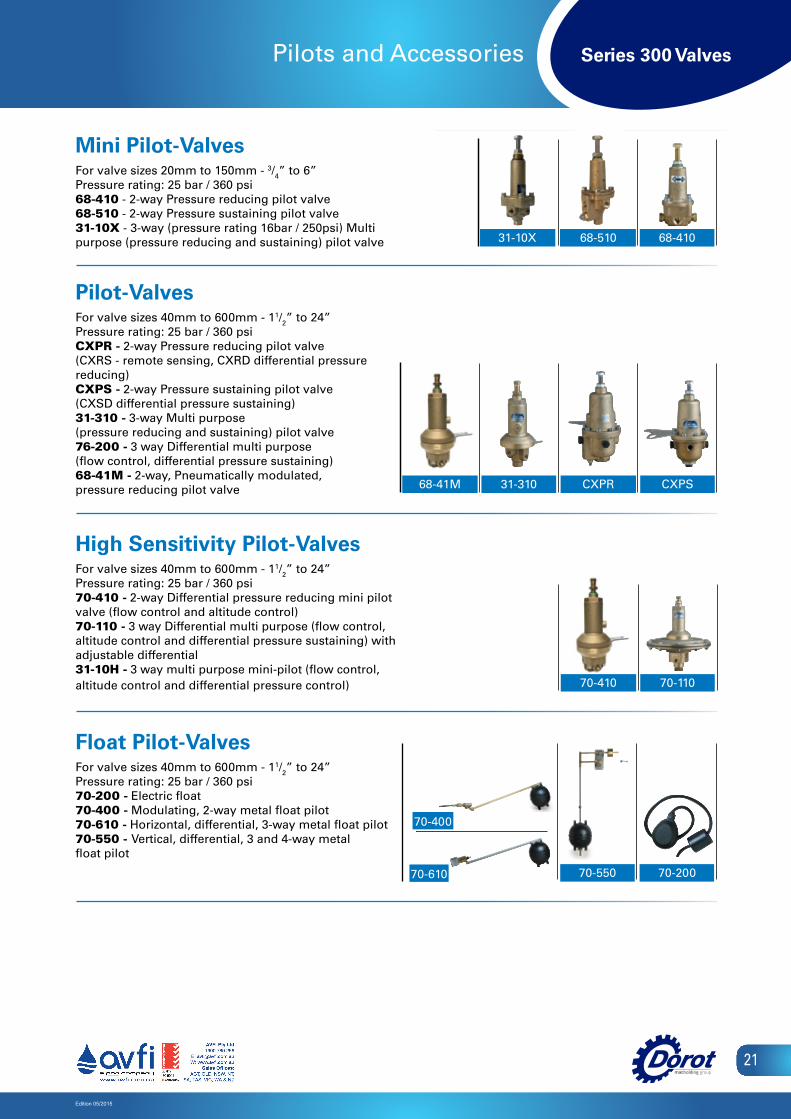
Mini Pilot-ValvesFor valve sizes 20mm to 150mm - 3/4” to 6”Pressure rating: 25 bar / 360 psi68-410 - 2-way Pressure reducing pilot valve68-510 - 2-way Pressure sustaining pilot valve31-10X - 3-way (pressure rating 16bar / 250psi) Multi purpose (pressure reducing and sustaining) pilot valve
Pilot-ValvesFor valve sizes 40mm to 600mm - 11/2” to 24”Pressure rating: 25 bar / 360 psiCXPR - 2-way Pressure reducing pilot valve (CXRS - remote sensing, CXRD differential pressure reducing)CXPS - 2-way Pressure sustaining pilot valve(CXSD differential pressure sustaining)31-310 - 3-way Multi purpose (pressure reducing and sustaining) pilot valve76-200 - 3 way Differential multi purpose(flow control, differential pressure sustaining)68-41M - 2-way, Pneumatically modulated, pressure reducing pilot valve
High Sensitivity Pilot-ValvesFor valve sizes 40mm to 600mm - 11/2” to 24”Pressure rating: 25 bar / 360 psi70-410 - 2-way Differential pressure reducing mini pilot valve (flow control and altitude control)70-110 - 3 way Differential multi purpose (flow control, altitude control and differential pressure sustaining) with adjustable differential31-10H - 3 way multi purpose mini-pilot (flow control, altitude control and differential pressure control)
Float Pilot-ValvesFor valve sizes 40mm to 600mm - 11/2” to 24”Pressure rating: 25 bar / 360 psi70-200 - Electric float70-400 - Modulating, 2-way metal float pilot70-610 - Horizontal, differential, 3-way metal float pilot70-550 - Vertical, differential, 3 and 4-way metal float pilot
32
Plastic Mini PilotsFor valve sizes 20mm to 100mm - 3/4" to 4"Pressure rating: 10 bar / 145 psi29-100 - 3-way pressure reducing pilot valve29-200 - 3-way multi purpose (pressure reducing and sustaining) pilot valve29-300 - 3 way differential multi purpose
(flow control, differential pressure sustaining)29-410 - 2-way pressure reducing pilot valve
Metal Mini PilotsFor valve sizes 20mm to 150mm - 3/4" to 6"Pressure rating: 25 bar / 360 psi68-410 - 2-way pressure reducing pilot valve68-500 - 2-way pressure sustaining pilot valve29-110 - 3-way (pressure rating 16bar / 230psi) pressure reducing pilot valve
Metal PilotsFor valve sizes 40mm to 600mm - 11/2" to 24"Pressure rating: 25 bar / 360 psiCXPR - 2-way pressure reducing pilot valve
(CXRS - remote sensing, CXRD differential pressure reducing)CXPS - 2-way pressure sustaining pilot valve
(CXSD differential pressure sustaining)31-310 - 3-way multi purpose (pressure reducing and sustaining) pilot valve76-200 - 3 way differential multi purpose
(flow control, differential pressure sustaining)68-600 - 2-way pressure reducing pilot valve68-700 - 2-way pressure sustaining pilot valve
High Sensitivity Metal PilotsFor valve sizes 40mm to 600mm - 11/2" to 24"Pressure rating: 25 bar / 360 psi70-410 - 2-way differential pressure reducing mini pilot valve (flow control and altitude control)76-600 - 2-way differential pressure reducing pilot valve (flow control and altitude control)70-110 - 3 way differential multi purpose (flow control, altitude control and differential pressure
sustaining) with adjustable differential
Float PilotsFor valve sizes 40mm to 600mm - 1 1/2" to 24"Pressure rating: 25 bar / 360 psi70-200 - Electric float70-300 - Modulating, 2-way plastic float pilot for irrigation use
(pressure rating: 8 bar / 115 psi)70-400 - Modulating, 2-way metal float pilot70-610 - Horizontal, differential, 3-way metal float pilot70-550 - Vertical, differential, 3 and 4-way metal float pilot
CONTROL VALVESDorot E V E R Y T H I N G I S U N D E R C O N T R O L
Pilots and Accessories
29-410 29-100 29-300 29-200
Series 100
76-61070-410 70-110
68-500 68-410
68-600/68-700 31-310 CXPR CXPS
70-400
70-300
70-61070-550 70-200
31-10X
68-41M
68-510 68-410
31-310 CXPR CXPS
70-410 70-110
70-20070-550
70-400
70-610

Series 300 Valves
Edition 05/2015
22
Pilots And Accessories
Relay-ValvesFor valve sizes 40mm to 600mm - 11/2” to 24”Pressure rating: 25 bar / 360 psi66-210 3-way / 2 positions NO (66-213: NC) hydraulic relay66-310 3-way adjustable hydraulic relay28-200 2-way / 2 positions hydraulic relay28-300 3-way / 2 positions NO/NC hydraulic relay
Heavy-duty Solenoid ValvesFor valve sizes 20mm to 600mm - 3/4” to 24”Pressure rating: According to the selected orifice and solenoid typeOperating Voltage (others available upon request):AC: 24V, 110V or 220VDC: 12V or 24VLatch 9V, 12V, 24VB2 2-way NC or NO solenoid valveB3 3-way NC or NO solenoid valve
Control FiltersSelf-Flushing, Inline Stainless steel screen filter located within the main valve, and rinsed continuously by the streamSizes: 1/4”,
1/2”, 1External, “Y” type Stainless steel screen installed in a “Y”shaped body on the pressure source.Sizes: 3/8”,
1/2”External, large - A large volume external filter
33CONTROL VALVESDorot E V E R Y T H I N G I S U N D E R C O N T R O L
Pilots and Accessories
Plastic RelaysFor valve sizes 20mm to 150mm - 3/4" to 6"Pressure rating: 10 bar / 145 psi25-300 3-way / 2 positions NO w. 3/8" ports hydraulic relay‘Galit’ 3-way / 2 positions NC or NO, small hydraulic relay
Metal RelaysFor valve sizes 40mm to 600mm - 11/2" to 24"Pressure rating: 25 bar / 360 psi66-210 3-way / 2 positions NO (66-213: NC) hydraulic relay66-300 3-way adjustable hydraulic relay28-200 2-way / 2 positions hydraulic relay
Mini SolenoidsFor irrigation valve sizes 20mm to 150mm - 3/4" to 6"Pressure rating: 10 bar / 145 psiOperating Voltage:AC: 24VDC: 12V or 24VLatch 6-40VD2 2-way NC solenoid valveD3 3-way NC or NO solenoid valve
Heavy-duty SolenoidsFor valve sizes 20mm to 600mm - 3/4" to 24"Pressure rating: According to the selected orifice and solenoid typeOperating Voltage (others available upon request):AC: 24V, 110V or 220VDC: 12V or 24VLatch 9V, 12V, 24VB2 2-way NC or NO solenoid valveB3 3-way NC or NO solenoid valve
Control FiltersSelf-Flushing, Inline � Stainless steel screen filter, located within themain valve, and rinsed continuously by the streamSizes: 1/4", 1/2"External, "Y" type - Stainless steel screen installed in a "Y"shaped body on the pressure source.Sizes: 3/8", 1/2"External, large - A large volume external filter
66-210 66-310 28-200
B2 B3
“Y Filter” Self Flushing Filter
‘GALIT’ 25-300
D2 D3
Series 100
28-300 66-210 66-310 28-200
B2 B3
Filtro en "Y" Filtro autolimpiante
Series 300 Valves
Edition 05/2015
23
Other Dorot Products
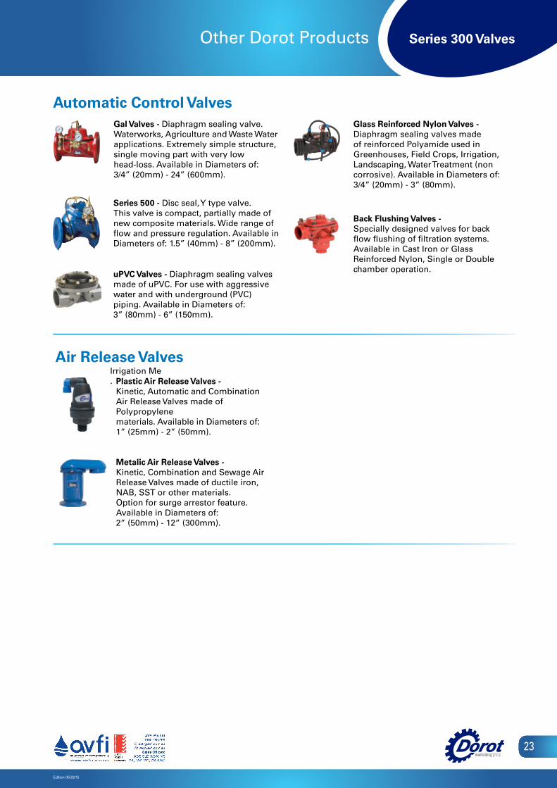
Automatic Control Valves
Plastic Air Release Valves -Kinetic, Automatic and CombinationAir Release Valves made of Polypropylenematerials. Available in Diameters of:1” (25mm) - 2” (50mm).
Metalic Air Release Valves - Kinetic, Combination and Sewage Air Release Valves made of ductile iron, NAB, SST or other materials. Option for surge arrestor feature. Available in Diameters of: 2” (50mm) - 12” (300mm).
Air Release ValvesIrrigation Me.
Series 500 - Disc seal, Y type valve.This valve is compact, partially made ofnew composite materials. Wide range offlow and pressure regulation. Available in Diameters of: 1.5” (40mm) - 8” (200mm).
uPVC Valves - Diaphragm sealing valvesmade of uPVC. For use with aggressivewater and with underground (PVC)piping. Available in Diameters of:3” (80mm) - 6” (150mm).
Glass Reinforced Nylon Valves -Diaphragm sealing valves made of reinforced Polyamide used in Greenhouses, Field Crops, Irrigation, Landscaping, Water Treatment (non corrosive). Available in Diameters of: 3/4” (20mm) - 3” (80mm).
Back Flushing Valves -Specially designed valves for back flow flushing of filtration systems. Available in Cast Iron or Glass Reinforced Nylon, Single or Double chamber operation.
Gal Valves - Diaphragm sealing valve.Waterworks, Agriculture and Waste Waterapplications. Extremely simple structure, single moving part with very low head-loss. Available in Diameters of: 3/4” (20mm) - 24” (600mm).

ReliabilityReliability
Innovation
ExpertiseInnovation
Expertise
Hundreds of companies in the industrial, civil engineering, municipal and agricultural sectors around the world have chosen DOROT’s innovative and field-proven technologies. Since its establishment in 1946, DOROT leads the valves market with continued innovation, uncompromising excellence and firm commitment to its customers, consulting and supporting them through all stages of a project and overcoming challenges in R&D, design, implementation, and maintenance.
China
Australia
Italy
SpainIsrael
Argentina
USA
Mexico