Embed Size (px)
Citation preview
Information Sheet T 8000-4 EN
Edition January 2017Information Sheet for control valves T 8000-1Information Sheet for materials T 8000-2Information Sheet for flow coefficients T 8000-3
Series 240 · 250 · 280Pneumatic Control ValvesInformation Sheet Part 4Permissible differential pressures for valves Type 3241 · Type 3251 · Type 3254 · Type 3256 Type 3281 · Type 3284 · Type 3286
2 T 8000-4 EN
T 8000-4 EN 3
Inhalt
Notes concerning selection 4Instrumentation 4Electric control valves 4Note concerning ANSI versions 5
Valve versions according to DIN EN standards 6
Permissible differential pressures for Type 3241 Globe Valve up to DN 150 6
Metal seal · Leakage class IV according to IEC 60534‑4 · Unbalanced 6Soft seal · Leakage class VI according to IEC 60534‑4 · Unbalanced 8Metal seal · Leakage class IV according to IEC 60534‑4 · Unbalanced · 19 mm operating travel 10Soft seal · Leakage class VI according to IEC 60534‑4 · Unbalanced · 19 mm operating travel 10Note concerning other versions 11
Permissible differential pressures for Type 325x and Type 328x Globe Valves as well as Type 3256 and Type 3286 Angle Valves up to DN 150 12
Metal seal · Leakage class IV according to IEC 60534‑4 · With correction value for bellows seal 12Soft seal · Leakage class VI according to IEC 60534‑4 · With correction value for bellows seal 14Note concerning other versions 15
Permissible differential pressures for Type 3241, Type 325x and Type 328x Globe Valves as well as Type 3256 and Type 3286 Angle Valves in DN 200 and larger 16
Metal seal · Leakage class IV according to IEC 60534‑4 · With correction value for bellows seal 16Soft seal · Leakage class VI according to IEC 60534‑4 · With correction value for bellows seal 17Note concerning other versions 17
Valve versions according to ANSI/ASTM standards 18
Permissible differential pressures for Type 3241 Globe Valve up to NPS 6 18
Metal seal · Leakage class IV according to ANSI/FCI 70‑2 · Unbalanced 18Soft seal · Leakage class VI according to ANSI/FCI 70‑2 · Unbalanced 20Metal seal · Leakage class IV according to ANSI/FCI 70‑2 · Unbalanced 19 mm operating travel 22Soft seal · Leakage class VI according to ANSI/FCI 70‑2 · Unbalanced 19 mm operating travel 22Note concerning other versions 23
Permissible differential pressures for Type 325x and Type 328x Globe Valves as well as Type 3256 and Type 3286 Angle Valves up to NPS 6 24
Metal seal · Leakage class IV according to ANSI/FCI 70‑2 · With correction value for bellows seal 24Soft seal · Leakage class VI according to ANSI/FCI 70‑2 · With correction value for bellows seal 26Note concerning other versions 27
Permissible differential pressures for Type 3241, Type 325x and Type 328x Globe Valves as well as Type 3256 and Type 3286 Angle Valves in NPS 8 and larger 28
Metal seal · Leakage class IV according to ANSI/FCI 70‑2 · With correction value for bellows seal 28Soft seal · Leakage class VI according to ANSI/FCI 70‑2 · With correction value for bellows seal 29Note concerning other versions 29
4 T 8000-4 EN
Notes concerning selection1. The specified differential pressures are based on the oper‑
ating range.2. The differential pressure specifications apply to adjustable
and self‑adjusting packings made of PTFE or graphite.3. The specified differential pressures are based on the stan‑
dard plug (parabolic and V‑port plugs). The SAMSON Valve Sizing software must be used to determine the dif‑ferential pressures of versions with perforated plug or AC trim.
4. The flow‑to‑open direction always applies.5. For versions with bellows seal (Tables 2.x, 3.x, 5.x, 6.x)
the permissible differential pressure of the closed valve is reduced by the correction value for the bellows seal.Example taken from Table 2.1:
Valve: DN 50 to 100KVS 100700 cm² actuator areaOperating range 2.1 to 3.3 bar
Table values: Δp = 24.5 barBellows correction value = –0.9 bar
Corrected permissible differential pressure
24.5 bar – 0.9 bar = 23.6 bar
NOTICEThe specified differential pressures provide an over-view for various valve versions and were calculated taking into account the above listed parameters. This Information Sheet and the data specified in it do not replace the exact calculation of the differential pres-sures using the SAMSON Valve Sizing software for each individual case.
InstrumentationFor accessories (e.g. quick exhaust valves) with a minimum supply pressure, make sure that the lower operating range value is higher than the minimum supply pressure for throttling service.
Electric control valvesDifferential pressures for the electric control valves are listed in the data sheets of the corresponding electric actuators.
T 8000-4 EN 5
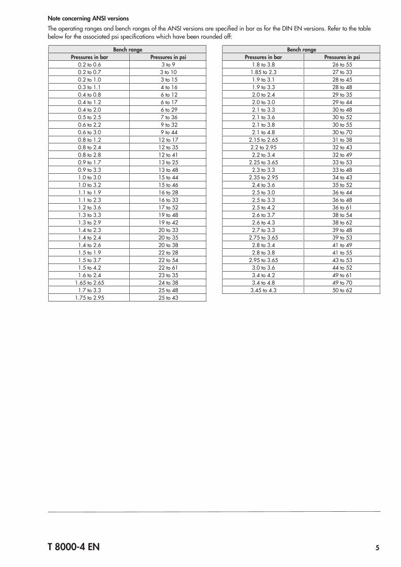
Note concerning ANSI versionsThe operating ranges and bench ranges of the ANSI versions are specified in bar as for the DIN EN versions. Refer to the table below for the associated psi specifications which have been rounded off:
Bench rangePressures in bar Pressures in psi
0.2 to 0.6 3 to 90.2 to 0.7 3 to 100.2 to 1.0 3 to 150.3 to 1.1 4 to 160.4 to 0.8 6 to 120.4 to 1.2 6 to 170.4 to 2.0 6 to 290.5 to 2.5 7 to 360.6 to 2.2 9 to 320.6 to 3.0 9 to 440.8 to 1.2 12 to 170.8 to 2.4 12 to 350.8 to 2.8 12 to 410.9 to 1.7 13 to 250.9 to 3.3 13 to 481.0 to 3.0 15 to 441.0 to 3.2 15 to 461.1 to 1.9 16 to 281.1 to 2.3 16 to 331.2 to 3.6 17 to 521.3 to 3.3 19 to 481.3 to 2.9 19 to 421.4 to 2.3 20 to 331.4 to 2.4 20 to 351.4 to 2.6 20 to 381.5 to 1.9 22 to 281.5 to 3.7 22 to 541.5 to 4.2 22 to 611.6 to 2.4 23 to 35
1.65 to 2.65 24 to 381.7 to 3.3 25 to 48
1.75 to 2.95 25 to 43
Bench rangePressures in bar Pressures in psi
1.8 to 3.8 26 to 551.85 to 2.3 27 to 331.9 to 3.1 28 to 451.9 to 3.3 28 to 482.0 to 2.4 29 to 352.0 to 3.0 29 to 442.1 to 3.3 30 to 482.1 to 3.6 30 to 522.1 to 3.8 30 to 552.1 to 4.8 30 to 70
2.15 to 2.65 31 to 382.2 to 2.95 32 to 432.2 to 3.4 32 to 49
2.25 to 3.65 33 to 532.3 to 3.3 33 to 48
2.35 to 2.95 34 to 432.4 to 3.6 35 to 522.5 to 3.0 36 to 442.5 to 3.3 36 to 482.5 to 4.2 36 to 612.6 to 3.7 38 to 542.6 to 4.3 38 to 622.7 to 3.3 39 to 48
2.75 to 3.65 39 to 532.8 to 3.4 41 to 492.8 to 3.8 41 to 55
2.95 to 3.65 43 to 533.0 to 3.6 44 to 523.4 to 4.2 49 to 613.4 to 4.8 49 to 703.45 to 4.3 50 to 62
6 T 8000-4 EN
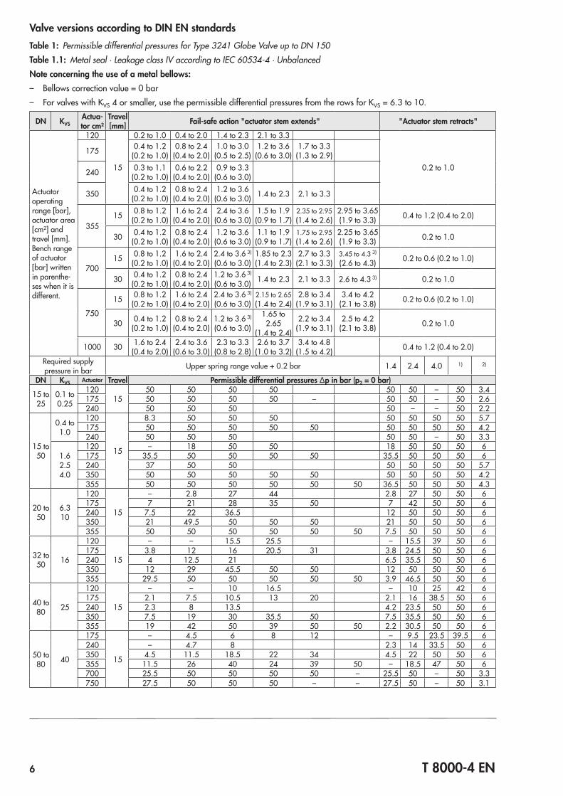
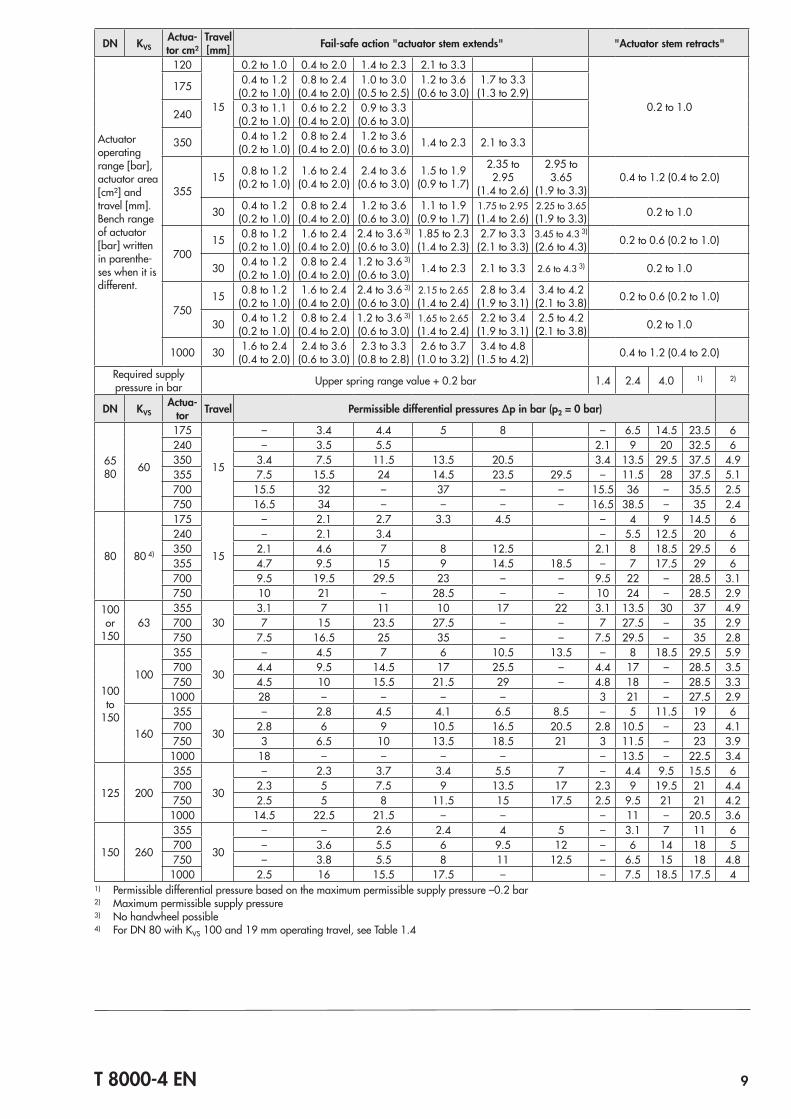
Valve versions according to DIN EN standardsTable 1: Permissible differential pressures for Type 3241 Globe Valve up to DN 150Table 1.1: Metal seal · Leakage class IV according to IEC 60534‑4 · UnbalancedNote concerning the use of a metal bellows: – Bellows correction value = 0 bar – For valves with KVS 4 or smaller, use the permissible differential pressures from the rows for KVS = 6.3 to 10.
DN KVSActua-tor cm²
Travel [mm] Fail-safe action "actuator stem extends" "Actuator stem retracts"
Actuator operating range [bar], actuator area [cm²] and travel [mm].Bench range of actuator [bar] written in parenthe‑ses when it is different.
120
15
0.2 to 1.0 0.4 to 2.0 1.4 to 2.3 2.1 to 3.3
0.2 to 1.0
175 0.4 to 1.2(0.2 to 1.0)
0.8 to 2.4(0.4 to 2.0)
1.0 to 3.0(0.5 to 2.5)
1.2 to 3.6(0.6 to 3.0)
1.7 to 3.3(1.3 to 2.9)
240 0.3 to 1.1(0.2 to 1.0)
0.6 to 2.2(0.4 to 2.0)
0.9 to 3.3(0.6 to 3.0)
350 0.4 to 1.2(0.2 to 1.0)
0.8 to 2.4(0.4 to 2.0)
1.2 to 3.6(0.6 to 3.0) 1.4 to 2.3 2.1 to 3.3
35515 0.8 to 1.2
(0.2 to 1.0)1.6 to 2.4
(0.4 to 2.0)2.4 to 3.6
(0.6 to 3.0)1.5 to 1.9
(0.9 to 1.7)2.35 to 2.95(1.4 to 2.6)
2.95 to 3.65(1.9 to 3.3) 0.4 to 1.2 (0.4 to 2.0)
30 0.4 to 1.2(0.2 to 1.0)
0.8 to 2.4(0.4 to 2.0)
1.2 to 3.6(0.6 to 3.0)
1.1 to 1.9(0.9 to 1.7)
1.75 to 2.95(1.4 to 2.6)
2.25 to 3.65(1.9 to 3.3) 0.2 to 1.0
70015 0.8 to 1.2
(0.2 to 1.0)1.6 to 2.4
(0.4 to 2.0)2.4 to 3.6 3)
(0.6 to 3.0)1.85 to 2.3(1.4 to 2.3)
2.7 to 3.3(2.1 to 3.3)
3.45 to 4.3 3)
(2.6 to 4.3) 0.2 to 0.6 (0.2 to 1.0)
30 0.4 to 1.2(0.2 to 1.0)
0.8 to 2.4(0.4 to 2.0)
1.2 to 3.6 3)
(0.6 to 3.0) 1.4 to 2.3 2.1 to 3.3 2.6 to 4.3 3) 0.2 to 1.0
750
15 0.8 to 1.2(0.2 to 1.0)
1.6 to 2.4(0.4 to 2.0)
2.4 to 3.6 3)
(0.6 to 3.0)2.15 to 2.65(1.4 to 2.4)
2.8 to 3.4(1.9 to 3.1)
3.4 to 4.2(2.1 to 3.8) 0.2 to 0.6 (0.2 to 1.0)
30 0.4 to 1.2(0.2 to 1.0)
0.8 to 2.4(0.4 to 2.0)
1.2 to 3.6 3)
(0.6 to 3.0)
1.65 to 2.65
(1.4 to 2.4)
2.2 to 3.4(1.9 to 3.1)
2.5 to 4.2(2.1 to 3.8) 0.2 to 1.0
1000 30 1.6 to 2.4(0.4 to 2.0)
2.4 to 3.6(0.6 to 3.0)
2.3 to 3.3(0.8 to 2.8)
2.6 to 3.7(1.0 to 3.2)
3.4 to 4.8(1.5 to 4.2) 0.4 to 1.2 (0.4 to 2.0)
Required supply pressure in bar Upper spring range value + 0.2 bar 1.4 2.4 4.0 1) 2)
DN KVS Actuator Travel Permissible differential pressures Δp in bar (p2 = 0 bar)
15 to 25
0.1 to 0.25
12015
50 50 50 50 50 50 – 50 3.4175 50 50 50 50 – 50 50 – 50 2.6240 50 50 50 50 – – 50 2.2
15 to 50
0.4 to 1.0
120
15
8.3 50 50 50 50 50 50 50 5.7175 50 50 50 50 50 50 50 50 50 4.2240 50 50 50 50 50 – 50 3.3
1.62.54.0
120 – 18 50 50 18 50 50 50 6175 35.5 50 50 50 50 35.5 50 50 50 6240 37 50 50 50 50 50 50 5.7350 50 50 50 50 50 50 50 50 50 4.2355 50 50 50 50 50 50 36.5 50 50 50 4.3
20 to 50
6.310
120
15
– 2.8 27 44 2.8 27 50 50 6175 7 21 28 35 50 7 42 50 50 6240 7.5 22 36.5 12 50 50 50 6350 21 49.5 50 50 50 21 50 50 50 6355 50 50 50 50 50 50 7.5 50 50 50 6
32 to 50 16
120
15
– – 15.5 25.5 – 15.5 39 50 6175 3.8 12 16 20.5 31 3.8 24.5 50 50 6240 4 12.5 21 6.5 35.5 50 50 6350 12 29 45.5 50 50 12 50 50 50 6355 29.5 50 50 50 50 50 3.9 46.5 50 50 6
40 to 80 25
120
15
– – 10 16.5 – 10 25 42 6175 2.1 7.5 10.5 13 20 2.1 16 38.5 50 6240 2.3 8 13.5 4.2 23.5 50 50 6350 7.5 19 30 35.5 50 7.5 35.5 50 50 6355 19 42 50 39 50 50 2.2 30.5 50 50 6
50 to 80 40
175
15
– 4.5 6 8 12 – 9.5 23.5 39.5 6240 – 4.7 8 2.3 14 33.5 50 6350 4.5 11.5 18.5 22 34 4.5 22 50 50 6355 11.5 26 40 24 39 50 – 18.5 47 50 6700 25.5 50 50 50 50 – 25.5 50 – 50 3.3750 27.5 50 50 50 – – 27.5 50 – 50 3.1
T 8000-4 EN 7
DN KVSActua-tor cm²
Travel [mm] Fail-safe action "actuator stem extends" "Actuator stem retracts"
Actuator operating range [bar], actuator area [cm²] and travel [mm].Bench range of actuator [bar] written in parenthe‑ses when it is different.
120
15
0.2 to 1.0 0.4 to 2.0 1.4 to 2.3 2.1 to 3.3
0.2 to 1.0
175 0.4 to 1.2(0.2 to 1.0)
0.8 to 2.4(0.4 to 2.0)
1.0 to 3.0(0.5 to 2.5)
1.2 to 3.6(0.6 to 3.0)
1.7 to 3.3(1.3 to 2.9)
240 0.3 to 1.1(0.2 to 1.0)
0.6 to 2.2(0.4 to 2.0)
0.9 to 3.3(0.6 to 3.0)
350 0.4 to 1.2(0.2 to 1.0)
0.8 to 2.4(0.4 to 2.0)
1.2 to 3.6(0.6 to 3.0) 1.4 to 2.3 2.1 to 3.3
35515 0.8 to 1.2
(0.2 to 1.0)1.6 to 2.4
(0.4 to 2.0)2.4 to 3.6
(0.6 to 3.0)1.5 to 1.9
(0.9 to 1.7)2.35 to 2.95(1.4 to 2.6)
2.95 to 3.65(1.9 to 3.3) 0.4 to 1.2 (0.4 to 2.0)
30 0.4 to 1.2(0.2 to 1.0)
0.8 to 2.4(0.4 to 2.0)
1.2 to 3.6(0.6 to 3.0)
1.1 to 1.9(0.9 to 1.7)
1.75 to 2.95(1.4 to 2.6)
2.25 to 3.65(1.9 to 3.3) 0.2 to 1.0
70015 0.8 to 1.2
(0.2 to 1.0)1.6 to 2.4
(0.4 to 2.0)2.4 to 3.6 3)
(0.6 to 3.0)1.85 to 2.3(1.4 to 2.3)
2.7 to 3.3(2.1 to 3.3)
3.45 to 4.3 3)
(2.6 to 4.3) 0.2 to 0.6 (0.2 to 1.0)
30 0.4 to 1.2(0.2 to 1.0)
0.8 to 2.4(0.4 to 2.0)
1.2 to 3.6 3)
(0.6 to 3.0) 1.4 to 2.3 2.1 to 3.3 2.6 to 4.3 3) 0.2 to 1.0
750
15 0.8 to 1.2(0.2 to 1.0)
1.6 to 2.4(0.4 to 2.0)
2.4 to 3.6 3)
(0.6 to 3.0)2.15 to 2.65(1.4 to 2.4)
2.8 to 3.4(1.9 to 3.1)
3.4 to 4.2(2.1 to 3.8) 0.2 to 0.6 (0.2 to 1.0)
30 0.4 to 1.2(0.2 to 1.0)
0.8 to 2.4(0.4 to 2.0)
1.2 to 3.6 3)
(0.6 to 3.0)
1.65 to 2.65
(1.4 to 2.4)
2.2 to 3.4(1.9 to 3.1)
2.5 to 4.2(2.1 to 3.8) 0.2 to 1.0
1000 30 1.6 to 2.4(0.4 to 2.0)
2.4 to 3.6(0.6 to 3.0)
2.3 to 3.3(0.8 to 2.8)
2.6 to 3.7(1.0 to 3.2)
3.4 to 4.8(1.5 to 4.2) 0.4 to 1.2 (0.4 to 2.0)
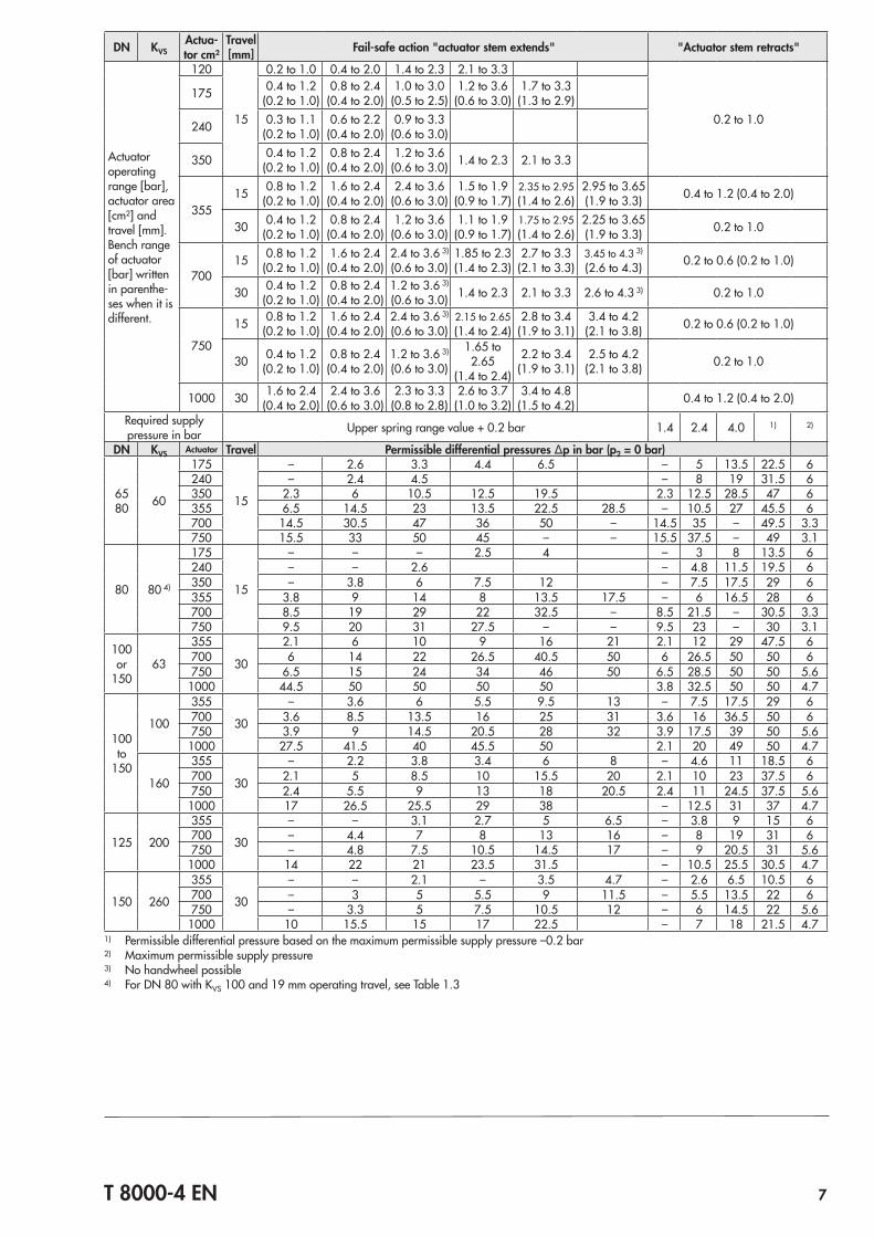
Required supply pressure in bar Upper spring range value + 0.2 bar 1.4 2.4 4.0 1) 2)
DN KVS Actuator Travel Permissible differential pressures Δp in bar (p2 = 0 bar)
6580 60
175
15
– 2.6 3.3 4.4 6.5 – 5 13.5 22.5 6240 – 2.4 4.5 – 8 19 31.5 6350 2.3 6 10.5 12.5 19.5 2.3 12.5 28.5 47 6355 6.5 14.5 23 13.5 22.5 28.5 – 10.5 27 45.5 6700 14.5 30.5 47 36 50 – 14.5 35 – 49.5 3.3750 15.5 33 50 45 – – 15.5 37.5 – 49 3.1
80 80 4)
175
15
– – – 2.5 4 – 3 8 13.5 6240 – – 2.6 – 4.8 11.5 19.5 6350 – 3.8 6 7.5 12 – 7.5 17.5 29 6355 3.8 9 14 8 13.5 17.5 – 6 16.5 28 6700 8.5 19 29 22 32.5 – 8.5 21.5 – 30.5 3.3750 9.5 20 31 27.5 – – 9.5 23 – 30 3.1
100 or
15063
355
30
2.1 6 10 9 16 21 2.1 12 29 47.5 6700 6 14 22 26.5 40.5 50 6 26.5 50 50 6750 6.5 15 24 34 46 50 6.5 28.5 50 50 5.6
1000 44.5 50 50 50 50 3.8 32.5 50 50 4.7
100 to
150
100
355
30
– 3.6 6 5.5 9.5 13 – 7.5 17.5 29 6700 3.6 8.5 13.5 16 25 31 3.6 16 36.5 50 6750 3.9 9 14.5 20.5 28 32 3.9 17.5 39 50 5.6
1000 27.5 41.5 40 45.5 50 2.1 20 49 50 4.7
160
355
30
– 2.2 3.8 3.4 6 8 – 4.6 11 18.5 6700 2.1 5 8.5 10 15.5 20 2.1 10 23 37.5 6750 2.4 5.5 9 13 18 20.5 2.4 11 24.5 37.5 5.61000 17 26.5 25.5 29 38 – 12.5 31 37 4.7
125 200
355
30
– – 3.1 2.7 5 6.5 – 3.8 9 15 6700 – 4.4 7 8 13 16 – 8 19 31 6750 – 4.8 7.5 10.5 14.5 17 – 9 20.5 31 5.6
1000 14 22 21 23.5 31.5 – 10.5 25.5 30.5 4.7
150 260
355
30
– – 2.1 – 3.5 4.7 – 2.6 6.5 10.5 6700 – 3 5 5.5 9 11.5 – 5.5 13.5 22 6750 – 3.3 5 7.5 10.5 12 – 6 14.5 22 5.6
1000 10 15.5 15 17 22.5 – 7 18 21.5 4.71) Permissible differential pressure based on the maximum permissible supply pressure –0.2 bar2) Maximum permissible supply pressure3) No handwheel possible4) For DN 80 with KVS 100 and 19 mm operating travel, see Table 1.3
8 T 8000-4 EN
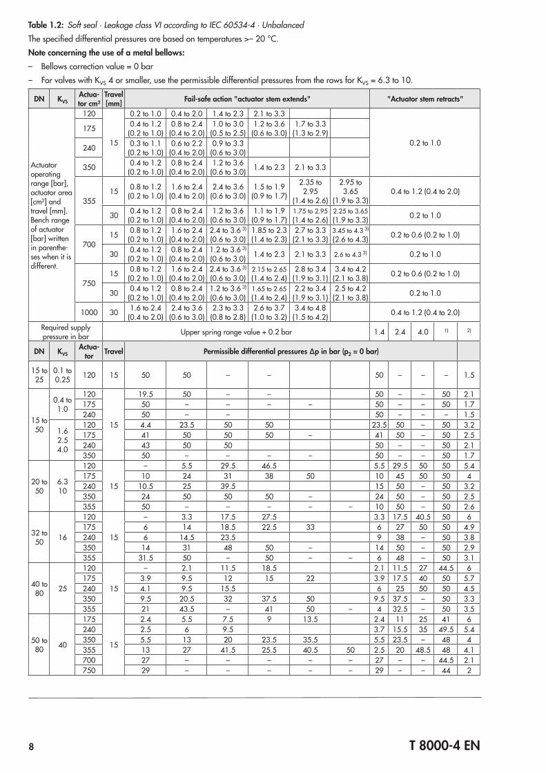
Table 1.2: Soft seal · Leakage class VI according to IEC 60534‑4 · UnbalancedThe specified differential pressures are based on temperatures >– 20 °C.Note concerning the use of a metal bellows: – Bellows correction value = 0 bar – For valves with KVS 4 or smaller, use the permissible differential pressures from the rows for KVS = 6.3 to 10.
DN KVSActua-tor cm²
Travel [mm] Fail-safe action "actuator stem extends" "Actuator stem retracts"
Actuator operating range [bar], actuator area [cm²] and travel [mm].Bench range of actuator [bar] written in parenthe‑ses when it is different.
120
15
0.2 to 1.0 0.4 to 2.0 1.4 to 2.3 2.1 to 3.3
0.2 to 1.0
175 0.4 to 1.2(0.2 to 1.0)
0.8 to 2.4(0.4 to 2.0)
1.0 to 3.0(0.5 to 2.5)
1.2 to 3.6(0.6 to 3.0)
1.7 to 3.3(1.3 to 2.9)
240 0.3 to 1.1(0.2 to 1.0)
0.6 to 2.2(0.4 to 2.0)
0.9 to 3.3(0.6 to 3.0)
350 0.4 to 1.2(0.2 to 1.0)
0.8 to 2.4(0.4 to 2.0)
1.2 to 3.6(0.6 to 3.0) 1.4 to 2.3 2.1 to 3.3
35515 0.8 to 1.2
(0.2 to 1.0)1.6 to 2.4
(0.4 to 2.0)2.4 to 3.6
(0.6 to 3.0)1.5 to 1.9
(0.9 to 1.7)
2.35 to 2.95
(1.4 to 2.6)
2.95 to 3.65
(1.9 to 3.3)0.4 to 1.2 (0.4 to 2.0)
30 0.4 to 1.2(0.2 to 1.0)
0.8 to 2.4(0.4 to 2.0)
1.2 to 3.6(0.6 to 3.0)
1.1 to 1.9(0.9 to 1.7)
1.75 to 2.95(1.4 to 2.6)
2.25 to 3.65(1.9 to 3.3) 0.2 to 1.0
70015 0.8 to 1.2
(0.2 to 1.0)1.6 to 2.4
(0.4 to 2.0)2.4 to 3.6 3)
(0.6 to 3.0)1.85 to 2.3(1.4 to 2.3)
2.7 to 3.3(2.1 to 3.3)
3.45 to 4.3 3)
(2.6 to 4.3) 0.2 to 0.6 (0.2 to 1.0)
30 0.4 to 1.2(0.2 to 1.0)
0.8 to 2.4(0.4 to 2.0)
1.2 to 3.6 3)
(0.6 to 3.0) 1.4 to 2.3 2.1 to 3.3 2.6 to 4.3 3) 0.2 to 1.0
75015 0.8 to 1.2
(0.2 to 1.0)1.6 to 2.4
(0.4 to 2.0)2.4 to 3.6 3)
(0.6 to 3.0)2.15 to 2.65(1.4 to 2.4)
2.8 to 3.4(1.9 to 3.1)
3.4 to 4.2(2.1 to 3.8) 0.2 to 0.6 (0.2 to 1.0)
30 0.4 to 1.2(0.2 to 1.0)
0.8 to 2.4(0.4 to 2.0)
1.2 to 3.6 3)
(0.6 to 3.0)1.65 to 2.65(1.4 to 2.4)
2.2 to 3.4(1.9 to 3.1)
2.5 to 4.2(2.1 to 3.8) 0.2 to 1.0
1000 30 1.6 to 2.4(0.4 to 2.0)
2.4 to 3.6(0.6 to 3.0)
2.3 to 3.3(0.8 to 2.8)
2.6 to 3.7(1.0 to 3.2)
3.4 to 4.8(1.5 to 4.2) 0.4 to 1.2 (0.4 to 2.0)
Required supply pressure in bar Upper spring range value + 0.2 bar 1.4 2.4 4.0 1) 2)
DN KVSActua-
tor Travel Permissible differential pressures Δp in bar (p2 = 0 bar)
15 to 25
0.1 to 0.25 120 15 50 50 – – 50 – – – 1.5
15 to 50
0.4 to 1.0
120
15
19.5 50 – – 50 – – 50 2.1175 50 – – – – 50 – – 50 1.7240 50 – – 50 – – – 1.5
1.6 2.5 4.0
120 4.4 23.5 50 50 23.5 50 – 50 3.2175 41 50 50 50 – 41 50 – 50 2.5240 43 50 50 50 – – 50 2.1350 50 – – – – 50 – – 50 1.7
20 to 50
6.310
120
15
– 5.5 29.5 46.5 5.5 29.5 50 50 5.4175 10 24 31 38 50 10 45 50 50 4240 10.5 25 39.5 15 50 – 50 3.2350 24 50 50 50 – 24 50 – 50 2.5355 50 – – – – – 10 50 – 50 2.6
32 to 50 16
120
15
– 3.3 17.5 27.5 3.3 17.5 40.5 50 6175 6 14 18.5 22.5 33 6 27 50 50 4.9240 6 14.5 23.5 9 38 – 50 3.8350 14 31 48 50 – 14 50 – 50 2.9355 31.5 50 – 50 – – 6 48 – 50 3.1
40 to 80 25
120
15
– 2.1 11.5 18.5 2.1 11.5 27 44.5 6175 3.9 9.5 12 15 22 3.9 17.5 40 50 5.7240 4.1 9.5 15.5 6 25 50 50 4.5350 9.5 20.5 32 37.5 50 9.5 37.5 – 50 3.3355 21 43.5 – 41 50 – 4 32.5 – 50 3.5
50 to 80 40
175
15
2.4 5.5 7.5 9 13.5 2.4 11 25 41 6240 2.5 6 9.5 3.7 15.5 35 49.5 5.4350 5.5 13 20 23.5 35.5 5.5 23.5 – 48 4355 13 27 41.5 25.5 40.5 50 2.5 20 48.5 48 4.1700 27 – – – – – 27 – – 44.5 2.1750 29 – – – – – 29 – – 44 2
T 8000-4 EN 9
DN KVSActua-tor cm²
Travel [mm] Fail-safe action "actuator stem extends" "Actuator stem retracts"
Actuator operating range [bar], actuator area [cm²] and travel [mm].Bench range of actuator [bar] written in parenthe‑ses when it is different.
120
15
0.2 to 1.0 0.4 to 2.0 1.4 to 2.3 2.1 to 3.3
0.2 to 1.0
175 0.4 to 1.2(0.2 to 1.0)
0.8 to 2.4(0.4 to 2.0)
1.0 to 3.0(0.5 to 2.5)
1.2 to 3.6(0.6 to 3.0)
1.7 to 3.3(1.3 to 2.9)
240 0.3 to 1.1(0.2 to 1.0)
0.6 to 2.2(0.4 to 2.0)
0.9 to 3.3(0.6 to 3.0)
350 0.4 to 1.2(0.2 to 1.0)
0.8 to 2.4(0.4 to 2.0)
1.2 to 3.6(0.6 to 3.0) 1.4 to 2.3 2.1 to 3.3
35515 0.8 to 1.2
(0.2 to 1.0)1.6 to 2.4
(0.4 to 2.0)2.4 to 3.6
(0.6 to 3.0)1.5 to 1.9
(0.9 to 1.7)
2.35 to 2.95
(1.4 to 2.6)
2.95 to 3.65
(1.9 to 3.3)0.4 to 1.2 (0.4 to 2.0)
30 0.4 to 1.2(0.2 to 1.0)
0.8 to 2.4(0.4 to 2.0)
1.2 to 3.6(0.6 to 3.0)
1.1 to 1.9(0.9 to 1.7)
1.75 to 2.95(1.4 to 2.6)
2.25 to 3.65(1.9 to 3.3) 0.2 to 1.0
70015 0.8 to 1.2
(0.2 to 1.0)1.6 to 2.4
(0.4 to 2.0)2.4 to 3.6 3)
(0.6 to 3.0)1.85 to 2.3(1.4 to 2.3)
2.7 to 3.3(2.1 to 3.3)
3.45 to 4.3 3)
(2.6 to 4.3) 0.2 to 0.6 (0.2 to 1.0)
30 0.4 to 1.2(0.2 to 1.0)
0.8 to 2.4(0.4 to 2.0)
1.2 to 3.6 3)
(0.6 to 3.0) 1.4 to 2.3 2.1 to 3.3 2.6 to 4.3 3) 0.2 to 1.0
75015 0.8 to 1.2
(0.2 to 1.0)1.6 to 2.4
(0.4 to 2.0)2.4 to 3.6 3)
(0.6 to 3.0)2.15 to 2.65(1.4 to 2.4)
2.8 to 3.4(1.9 to 3.1)
3.4 to 4.2(2.1 to 3.8) 0.2 to 0.6 (0.2 to 1.0)
30 0.4 to 1.2(0.2 to 1.0)
0.8 to 2.4(0.4 to 2.0)
1.2 to 3.6 3)
(0.6 to 3.0)1.65 to 2.65(1.4 to 2.4)
2.2 to 3.4(1.9 to 3.1)
2.5 to 4.2(2.1 to 3.8) 0.2 to 1.0
1000 30 1.6 to 2.4(0.4 to 2.0)
2.4 to 3.6(0.6 to 3.0)
2.3 to 3.3(0.8 to 2.8)
2.6 to 3.7(1.0 to 3.2)
3.4 to 4.8(1.5 to 4.2) 0.4 to 1.2 (0.4 to 2.0)
Required supply pressure in bar Upper spring range value + 0.2 bar 1.4 2.4 4.0 1) 2)
DN KVSActua-
tor Travel Permissible differential pressures Δp in bar (p2 = 0 bar)
65 80 60
175
15
– 3.4 4.4 5 8 – 6.5 14.5 23.5 6240 – 3.5 5.5 2.1 9 20 32.5 6350 3.4 7.5 11.5 13.5 20.5 3.4 13.5 29.5 37.5 4.9355 7.5 15.5 24 14.5 23.5 29.5 – 11.5 28 37.5 5.1700 15.5 32 – 37 – – 15.5 36 – 35.5 2.5750 16.5 34 – – – – 16.5 38.5 – 35 2.4
80 80 4)
175
15
– 2.1 2.7 3.3 4.5 – 4 9 14.5 6240 – 2.1 3.4 – 5.5 12.5 20 6350 2.1 4.6 7 8 12.5 2.1 8 18.5 29.5 6355 4.7 9.5 15 9 14.5 18.5 – 7 17.5 29 6700 9.5 19.5 29.5 23 – – 9.5 22 – 28.5 3.1750 10 21 – 28.5 – – 10 24 – 28.5 2.9
100 or
15063
35530
3.1 7 11 10 17 22 3.1 13.5 30 37 4.9700 7 15 23.5 27.5 – – 7 27.5 – 35 2.9750 7.5 16.5 25 35 – – 7.5 29.5 – 35 2.8
100 to
150
100
355
30
– 4.5 7 6 10.5 13.5 – 8 18.5 29.5 5.9700 4.4 9.5 14.5 17 25.5 – 4.4 17 – 28.5 3.5750 4.5 10 15.5 21.5 29 – 4.8 18 – 28.5 3.3
1000 28 – – – – 3 21 – 27.5 2.9
160
355
30
– 2.8 4.5 4.1 6.5 8.5 – 5 11.5 19 6700 2.8 6 9 10.5 16.5 20.5 2.8 10.5 – 23 4.1750 3 6.5 10 13.5 18.5 21 3 11.5 – 23 3.9
1000 18 – – – – – 13.5 – 22.5 3.4
125 200
355
30
– 2.3 3.7 3.4 5.5 7 – 4.4 9.5 15.5 6700 2.3 5 7.5 9 13.5 17 2.3 9 19.5 21 4.4750 2.5 5 8 11.5 15 17.5 2.5 9.5 21 21 4.2
1000 14.5 22.5 21.5 – – – 11 – 20.5 3.6
150 260
355
30
– – 2.6 2.4 4 5 – 3.1 7 11 6700 – 3.6 5.5 6 9.5 12 – 6 14 18 5750 – 3.8 5.5 8 11 12.5 – 6.5 15 18 4.8
1000 2.5 16 15.5 17.5 – – 7.5 18.5 17.5 41) Permissible differential pressure based on the maximum permissible supply pressure –0.2 bar2) Maximum permissible supply pressure3) No handwheel possible4) For DN 80 with KVS 100 and 19 mm operating travel, see Table 1.4
10 T 8000-4 EN
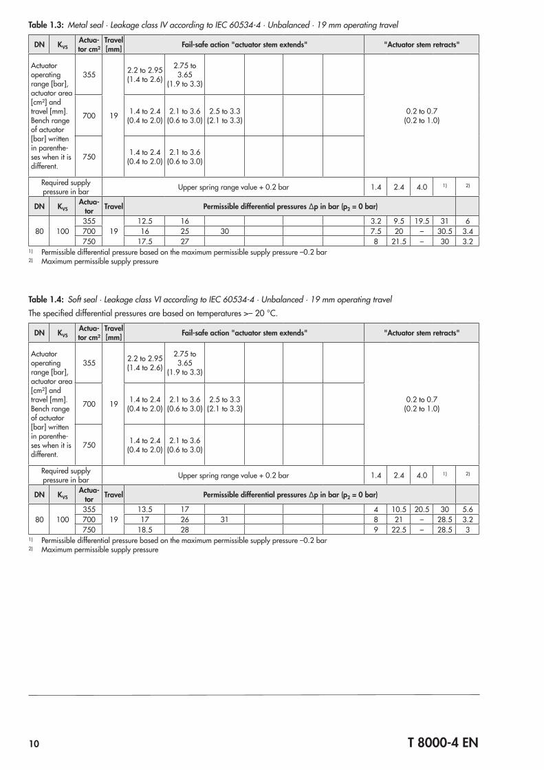
Table 1.3: Metal seal · Leakage class IV according to IEC 60534‑4 · Unbalanced · 19 mm operating travel
DN KVSActua-tor cm²
Travel [mm] Fail-safe action "actuator stem extends" "Actuator stem retracts"
Actuator operating range [bar], actuator area [cm²] and travel [mm].Bench range of actuator [bar] written in parenthe‑ses when it is different.
355
19
2.2 to 2.95(1.4 to 2.6)
2.75 to 3.65
(1.9 to 3.3)
0.2 to 0.7(0.2 to 1.0)700 1.4 to 2.4
(0.4 to 2.0)2.1 to 3.6
(0.6 to 3.0)2.5 to 3.3
(2.1 to 3.3)
750 1.4 to 2.4(0.4 to 2.0)
2.1 to 3.6(0.6 to 3.0)
Required supply pressure in bar Upper spring range value + 0.2 bar 1.4 2.4 4.0 1) 2)
DN KVSActua-
tor Travel Permissible differential pressures Δp in bar (p2 = 0 bar)
80 100355
1912.5 16 3.2 9.5 19.5 31 6
700 16 25 30 7.5 20 – 30.5 3.4750 17.5 27 8 21.5 – 30 3.2
1) Permissible differential pressure based on the maximum permissible supply pressure –0.2 bar2) Maximum permissible supply pressure
Table 1.4: Soft seal · Leakage class VI according to IEC 60534‑4 · Unbalanced · 19 mm operating travelThe specified differential pressures are based on temperatures >– 20 °C.
DN KVSActua-tor cm²
Travel [mm] Fail-safe action "actuator stem extends" "Actuator stem retracts"
Actuator operating range [bar], actuator area [cm²] and travel [mm].Bench range of actuator [bar] written in parenthe‑ses when it is different.
355
19
2.2 to 2.95(1.4 to 2.6)
2.75 to 3.65
(1.9 to 3.3)
0.2 to 0.7(0.2 to 1.0)700 1.4 to 2.4
(0.4 to 2.0)2.1 to 3.6
(0.6 to 3.0)2.5 to 3.3
(2.1 to 3.3)
750 1.4 to 2.4(0.4 to 2.0)
2.1 to 3.6(0.6 to 3.0)
Required supply pressure in bar Upper spring range value + 0.2 bar 1.4 2.4 4.0 1) 2)
DN KVSActua-
tor Travel Permissible differential pressures Δp in bar (p2 = 0 bar)
80 100355
1913.5 17 4 10.5 20.5 30 5.6
700 17 26 31 8 21 – 28.5 3.2750 18.5 28 9 22.5 – 28.5 3
1) Permissible differential pressure based on the maximum permissible supply pressure –0.2 bar2) Maximum permissible supply pressure
T 8000-4 EN 11
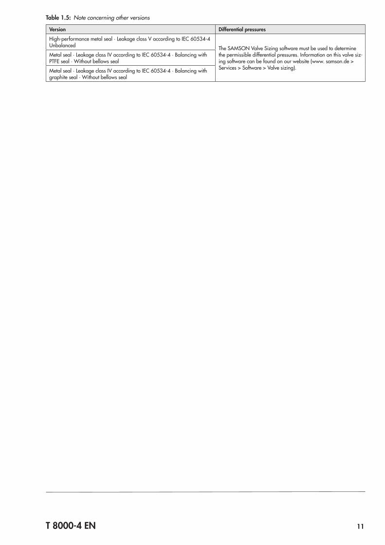
Table 1.5: Note concerning other versions
Version Differential pressures
High‑performance metal seal · Leakage class V according to IEC 60534‑4 Unbalanced The SAMSON Valve Sizing software must be used to determine
the permissible differential pressures. Information on this valve siz‑ing software can be found on our website (www. samson.de > Services > Software > Valve sizing).
Metal seal · Leakage class IV according to IEC 60534‑4 · Balancing with PTFE seal · Without bellows seal
Metal seal · Leakage class IV according to IEC 60534‑4 · Balancing with graphite seal · Without bellows seal
12 T 8000-4 EN
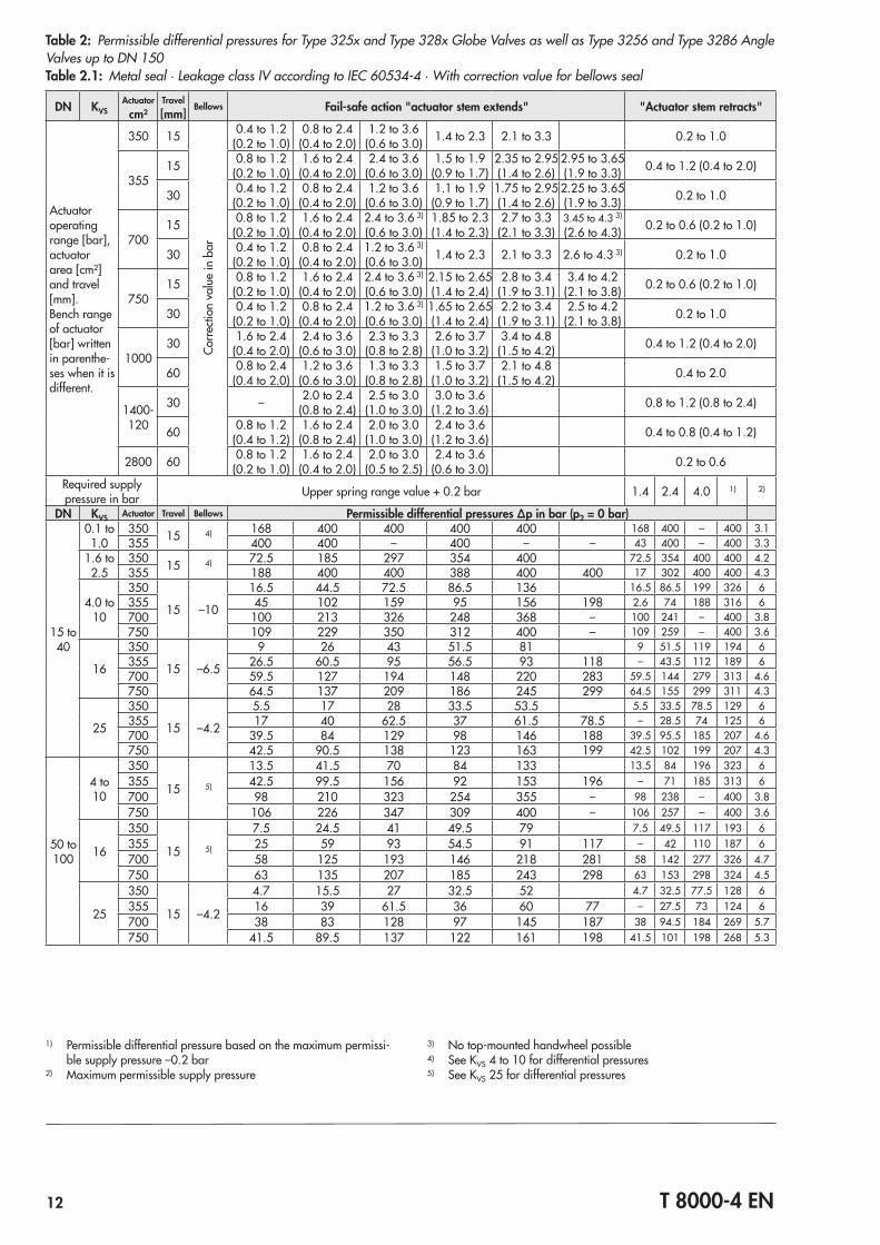
Table 2: Permissible differential pressures for Type 325x and Type 328x Globe Valves as well as Type 3256 and Type 3286 Angle Valves up to DN 150Table 2.1: Metal seal · Leakage class IV according to IEC 60534‑4 · With correction value for bellows seal
DN KVSActuator
cm²Travel [mm]
Bellows Fail-safe action "actuator stem extends" "Actuator stem retracts"
Actuator operating range [bar], actuator area [cm²] and travel [mm].Bench range of actuator [bar] written in parenthe‑ses when it is different.
350 15
Corre
ction
val
ue in
bar
0.4 to 1.2(0.2 to 1.0)
0.8 to 2.4(0.4 to 2.0)
1.2 to 3.6(0.6 to 3.0) 1.4 to 2.3 2.1 to 3.3 0.2 to 1.0
35515 0.8 to 1.2
(0.2 to 1.0)1.6 to 2.4
(0.4 to 2.0)2.4 to 3.6
(0.6 to 3.0)1.5 to 1.9
(0.9 to 1.7)2.35 to 2.95(1.4 to 2.6)
2.95 to 3.65(1.9 to 3.3) 0.4 to 1.2 (0.4 to 2.0)
30 0.4 to 1.2(0.2 to 1.0)
0.8 to 2.4(0.4 to 2.0)
1.2 to 3.6(0.6 to 3.0)
1.1 to 1.9(0.9 to 1.7)
1.75 to 2.95(1.4 to 2.6)
2.25 to 3.65(1.9 to 3.3) 0.2 to 1.0
70015 0.8 to 1.2
(0.2 to 1.0)1.6 to 2.4
(0.4 to 2.0)2.4 to 3.6 3)
(0.6 to 3.0)1.85 to 2.3(1.4 to 2.3)
2.7 to 3.3(2.1 to 3.3)
3.45 to 4.3 3)
(2.6 to 4.3) 0.2 to 0.6 (0.2 to 1.0)
30 0.4 to 1.2(0.2 to 1.0)
0.8 to 2.4(0.4 to 2.0)
1.2 to 3.6 3)
(0.6 to 3.0) 1.4 to 2.3 2.1 to 3.3 2.6 to 4.3 3) 0.2 to 1.0
75015 0.8 to 1.2
(0.2 to 1.0)1.6 to 2.4
(0.4 to 2.0)2.4 to 3.6 3)
(0.6 to 3.0)2.15 to 2.65(1.4 to 2.4)
2.8 to 3.4(1.9 to 3.1)
3.4 to 4.2(2.1 to 3.8) 0.2 to 0.6 (0.2 to 1.0)
30 0.4 to 1.2(0.2 to 1.0)
0.8 to 2.4(0.4 to 2.0)
1.2 to 3.6 3)
(0.6 to 3.0)1.65 to 2.65(1.4 to 2.4)
2.2 to 3.4(1.9 to 3.1)
2.5 to 4.2(2.1 to 3.8) 0.2 to 1.0
100030 1.6 to 2.4
(0.4 to 2.0)2.4 to 3.6
(0.6 to 3.0)2.3 to 3.3
(0.8 to 2.8)2.6 to 3.7
(1.0 to 3.2)3.4 to 4.8
(1.5 to 4.2) 0.4 to 1.2 (0.4 to 2.0)
60 0.8 to 2.4(0.4 to 2.0)
1.2 to 3.6(0.6 to 3.0)
1.3 to 3.3(0.8 to 2.8)
1.5 to 3.7(1.0 to 3.2)
2.1 to 4.8(1.5 to 4.2) 0.4 to 2.0
1400‑120
30 – 2.0 to 2.4(0.8 to 2.4)
2.5 to 3.0(1.0 to 3.0)
3.0 to 3.6(1.2 to 3.6) 0.8 to 1.2 (0.8 to 2.4)
60 0.8 to 1.2(0.4 to 1.2)
1.6 to 2.4 (0.8 to 2.4)
2.0 to 3.0(1.0 to 3.0)
2.4 to 3.6(1.2 to 3.6) 0.4 to 0.8 (0.4 to 1.2)
2800 60 0.8 to 1.2 (0.2 to 1.0)
1.6 to 2.4 (0.4 to 2.0)
2.0 to 3.0(0.5 to 2.5)
2.4 to 3.6(0.6 to 3.0) 0.2 to 0.6
Required supply pressure in bar Upper spring range value + 0.2 bar 1.4 2.4 4.0 1) 2)
DN KVS Actuator Travel Bellows Permissible differential pressures Δp in bar (p2 = 0 bar)
15 to 40
0.1 to 1.0
350 15 4) 168 400 400 400 400 168 400 – 400 3.1355 400 400 – 400 – – 43 400 – 400 3.3
1.6 to 2.5
350 15 4) 72.5 185 297 354 400 72.5 354 400 400 4.2355 188 400 400 388 400 400 17 302 400 400 4.3
4.0 to 10
350
15 –10
16.5 44.5 72.5 86.5 136 16.5 86.5 199 326 6355 45 102 159 95 156 198 2.6 74 188 316 6700 100 213 326 248 368 – 100 241 – 400 3.8750 109 229 350 312 400 – 109 259 – 400 3.6
16
350
15 –6.5
9 26 43 51.5 81 9 51.5 119 194 6355 26.5 60.5 95 56.5 93 118 – 43.5 112 189 6700 59.5 127 194 148 220 283 59.5 144 279 313 4.6750 64.5 137 209 186 245 299 64.5 155 299 311 4.3
25
350
15 –4.2
5.5 17 28 33.5 53.5 5.5 33.5 78.5 129 6355 17 40 62.5 37 61.5 78.5 – 28.5 74 125 6700 39.5 84 129 98 146 188 39.5 95.5 185 207 4.6750 42.5 90.5 138 123 163 199 42.5 102 199 207 4.3
50 to 100
4 to 10
350
15 5)
13.5 41.5 70 84 133 13.5 84 196 323 6355 42.5 99.5 156 92 153 196 – 71 185 313 6700 98 210 323 254 355 – 98 238 – 400 3.8750 106 226 347 309 400 – 106 257 – 400 3.6
16
350
15 5)
7.5 24.5 41 49.5 79 7.5 49.5 117 193 6355 25 59 93 54.5 91 117 – 42 110 187 6700 58 125 193 146 218 281 58 142 277 326 4.7750 63 135 207 185 243 298 63 153 298 324 4.5
25
350
15 –4.2
4.7 15.5 27 32.5 52 4.7 32.5 77.5 128 6355 16 39 61.5 36 60 77 – 27.5 73 124 6700 38 83 128 97 145 187 38 94.5 184 269 5.7750 41.5 89.5 137 122 161 198 41.5 101 198 268 5.3
1) Permissible differential pressure based on the maximum permissi‑ble supply pressure –0.2 bar
2) Maximum permissible supply pressure
3) No top‑mounted handwheel possible4) See KVS 4 to 10 for differential pressures5) See KVS 25 for differential pressures
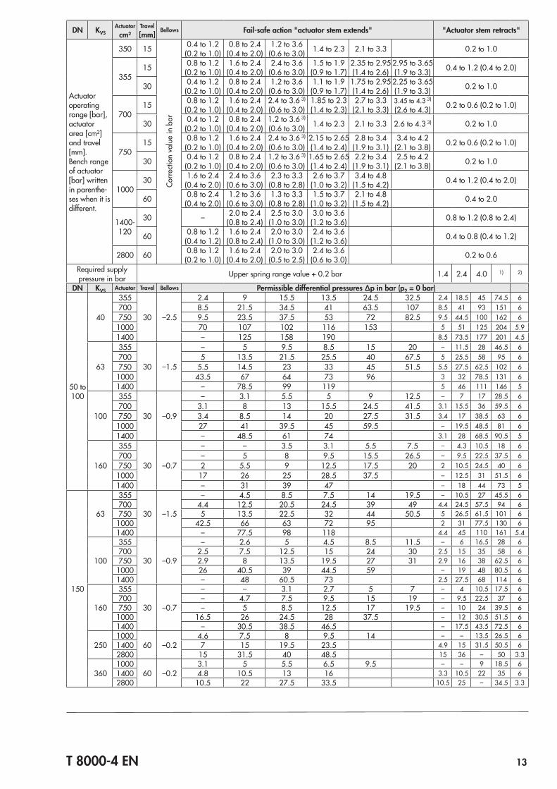
T 8000-4 EN 13
DN KVSActuator
cm²Travel [mm]
Bellows Fail-safe action "actuator stem extends" "Actuator stem retracts"
Actuator operating range [bar], actuator area [cm²] and travel [mm].Bench range of actuator [bar] written in parenthe‑ses when it is different.
350 15
Corre
ction
val
ue in
bar
0.4 to 1.2(0.2 to 1.0)
0.8 to 2.4(0.4 to 2.0)
1.2 to 3.6(0.6 to 3.0) 1.4 to 2.3 2.1 to 3.3 0.2 to 1.0
35515 0.8 to 1.2
(0.2 to 1.0)1.6 to 2.4
(0.4 to 2.0)2.4 to 3.6
(0.6 to 3.0)1.5 to 1.9
(0.9 to 1.7)2.35 to 2.95(1.4 to 2.6)
2.95 to 3.65(1.9 to 3.3) 0.4 to 1.2 (0.4 to 2.0)
30 0.4 to 1.2(0.2 to 1.0)
0.8 to 2.4(0.4 to 2.0)
1.2 to 3.6(0.6 to 3.0)
1.1 to 1.9(0.9 to 1.7)
1.75 to 2.95(1.4 to 2.6)
2.25 to 3.65(1.9 to 3.3) 0.2 to 1.0
70015 0.8 to 1.2
(0.2 to 1.0)1.6 to 2.4
(0.4 to 2.0)2.4 to 3.6 3)
(0.6 to 3.0)1.85 to 2.3(1.4 to 2.3)
2.7 to 3.3(2.1 to 3.3)
3.45 to 4.3 3)
(2.6 to 4.3) 0.2 to 0.6 (0.2 to 1.0)
30 0.4 to 1.2(0.2 to 1.0)
0.8 to 2.4(0.4 to 2.0)
1.2 to 3.6 3)
(0.6 to 3.0) 1.4 to 2.3 2.1 to 3.3 2.6 to 4.3 3) 0.2 to 1.0
75015 0.8 to 1.2
(0.2 to 1.0)1.6 to 2.4
(0.4 to 2.0)2.4 to 3.6 3)
(0.6 to 3.0)2.15 to 2.65(1.4 to 2.4)
2.8 to 3.4(1.9 to 3.1)
3.4 to 4.2(2.1 to 3.8) 0.2 to 0.6 (0.2 to 1.0)
30 0.4 to 1.2(0.2 to 1.0)
0.8 to 2.4(0.4 to 2.0)
1.2 to 3.6 3)
(0.6 to 3.0)1.65 to 2.65(1.4 to 2.4)
2.2 to 3.4(1.9 to 3.1)
2.5 to 4.2(2.1 to 3.8) 0.2 to 1.0
100030 1.6 to 2.4
(0.4 to 2.0)2.4 to 3.6
(0.6 to 3.0)2.3 to 3.3
(0.8 to 2.8)2.6 to 3.7
(1.0 to 3.2)3.4 to 4.8
(1.5 to 4.2) 0.4 to 1.2 (0.4 to 2.0)
60 0.8 to 2.4(0.4 to 2.0)
1.2 to 3.6(0.6 to 3.0)
1.3 to 3.3(0.8 to 2.8)
1.5 to 3.7(1.0 to 3.2)
2.1 to 4.8(1.5 to 4.2) 0.4 to 2.0
1400‑120
30 – 2.0 to 2.4(0.8 to 2.4)
2.5 to 3.0(1.0 to 3.0)
3.0 to 3.6(1.2 to 3.6) 0.8 to 1.2 (0.8 to 2.4)
60 0.8 to 1.2(0.4 to 1.2)
1.6 to 2.4 (0.8 to 2.4)
2.0 to 3.0(1.0 to 3.0)
2.4 to 3.6(1.2 to 3.6) 0.4 to 0.8 (0.4 to 1.2)
2800 60 0.8 to 1.2 (0.2 to 1.0)
1.6 to 2.4 (0.4 to 2.0)
2.0 to 3.0(0.5 to 2.5)
2.4 to 3.6(0.6 to 3.0) 0.2 to 0.6
Required supply pressure in bar Upper spring range value + 0.2 bar 1.4 2.4 4.0 1) 2)
DN KVS Actuator Travel Bellows Permissible differential pressures Δp in bar (p2 = 0 bar)
50 to 100
40
355
30 –2.5
2.4 9 15.5 13.5 24.5 32.5 2.4 18.5 45 74.5 6700 8.5 21.5 34.5 41 63.5 107 8.5 41 93 151 6750 9.5 23.5 37.5 53 72 82.5 9.5 44.5 100 162 6
1000 70 107 102 116 153 5 51 125 204 5.91400 – 125 158 190 8.5 73.5 177 201 4.5
63
355
30 –1.5
– 5 9.5 8.5 15 20 – 11.5 28 46.5 6700 5 13.5 21.5 25.5 40 67.5 5 25.5 58 95 6750 5.5 14.5 23 33 45 51.5 5.5 27.5 62.5 102 6
1000 43.5 67 64 73 96 3 32 78.5 131 61400 – 78.5 99 119 5 46 111 146 5
100
355
30 –0.9
– 3.1 5.5 5 9 12.5 – 7 17 28.5 6700 3.1 8 13 15.5 24.5 41.5 3.1 15.5 36 59.5 6750 3.4 8.5 14 20 27.5 31.5 3.4 17 38.5 63 6
1000 27 41 39.5 45 59.5 – 19.5 48.5 81 61400 – 48.5 61 74 3.1 28 68.5 90.5 5
160
355
30 –0.7
– – 3.5 3.1 5.5 7.5 – 4.3 10.5 18 6700 – 5 8 9.5 15.5 26.5 – 9.5 22.5 37.5 6750 2 5.5 9 12.5 17.5 20 2 10.5 24.5 40 6
1000 17 26 25 28.5 37.5 – 12.5 31 51.5 61400 – 31 39 47 – 18 44 73 5
150
63
355
30 –1.5
– 4.5 8.5 7.5 14 19.5 – 10.5 27 45.5 6700 4.4 12.5 20.5 24.5 39 49 4.4 24.5 57.5 94 6750 5 13.5 22.5 32 44 50.5 5 26.5 61.5 101 6
1000 42.5 66 63 72 95 2 31 77.5 130 61400 – 77.5 98 118 4.4 45 110 161 5.4
100
355
30 –0.9
– 2.6 5 4.5 8.5 11.5 – 6 16.5 28 6700 2.5 7.5 12.5 15 24 30 2.5 15 35 58 6750 2.9 8 13.5 19.5 27 31 2.9 16 38 62.5 6
1000 26 40.5 39 44.5 59 – 19 48 80.5 61400 – 48 60.5 73 2.5 27.5 68 114 6
160
355
30 –0.7
– – 3.1 2.7 5 7 – 4 10.5 17.5 6700 – 4.7 7.5 9.5 15 19 – 9.5 22.5 37 6750 – 5 8.5 12.5 17 19.5 – 10 24 39.5 6
1000 16.5 26 24.5 28 37.5 – 12 30.5 51.5 61400 – 30.5 38.5 46.5 – 17.5 43.5 72.5 6
2501000
60 –0.24.6 7.5 8 9.5 14 – – 13.5 26.5 6
1400 7 15 19.5 23.5 4.9 15 31.5 50.5 62800 15 31.5 40 48.5 15 36 – 50 3.3
3601000
60 –0.23.1 5 5.5 6.5 9.5 – – 9 18.5 6
1400 4.8 10.5 13 16 3.3 10.5 22 35 62800 10.5 22 27.5 33.5 10.5 25 – 34.5 3.3
14 T 8000-4 EN
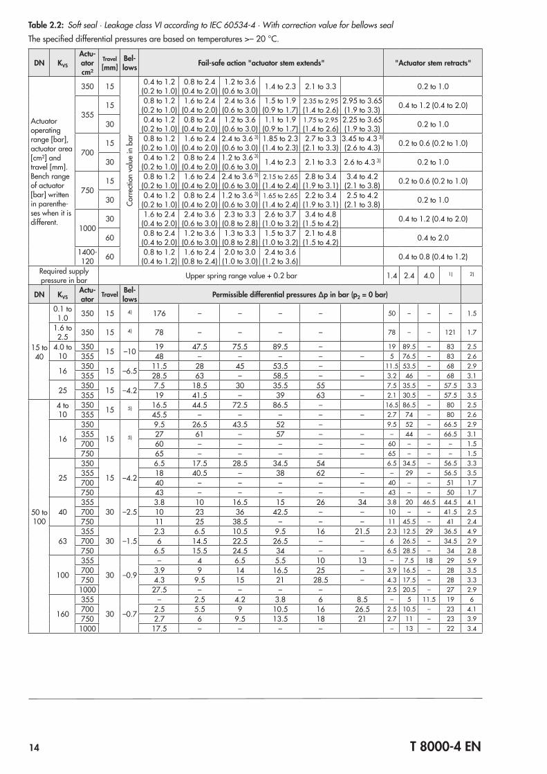
Table 2.2: Soft seal · Leakage class VI according to IEC 60534‑4 · With correction value for bellows sealThe specified differential pressures are based on temperatures >– 20 °C.
DN KVS
Actu-ator cm²
Travel [mm]
Bel-lows Fail-safe action "actuator stem extends" "Actuator stem retracts"
Actuator operating range [bar], actuator area [cm²] and travel [mm].Bench range of actuator [bar] written in parenthe‑ses when it is different.
350 15
Corre
ction
val
ue in
bar
0.4 to 1.2(0.2 to 1.0)
0.8 to 2.4(0.4 to 2.0)
1.2 to 3.6(0.6 to 3.0) 1.4 to 2.3 2.1 to 3.3 0.2 to 1.0
35515 0.8 to 1.2
(0.2 to 1.0)1.6 to 2.4
(0.4 to 2.0)2.4 to 3.6
(0.6 to 3.0)1.5 to 1.9
(0.9 to 1.7)2.35 to 2.95(1.4 to 2.6)
2.95 to 3.65(1.9 to 3.3) 0.4 to 1.2 (0.4 to 2.0)
30 0.4 to 1.2(0.2 to 1.0)
0.8 to 2.4(0.4 to 2.0)
1.2 to 3.6(0.6 to 3.0)
1.1 to 1.9(0.9 to 1.7)
1.75 to 2.95(1.4 to 2.6)
2.25 to 3.65(1.9 to 3.3) 0.2 to 1.0
70015 0.8 to 1.2
(0.2 to 1.0)1.6 to 2.4
(0.4 to 2.0)2.4 to 3.6 3)
(0.6 to 3.0)1.85 to 2.3(1.4 to 2.3)
2.7 to 3.3(2.1 to 3.3)
3.45 to 4.3 3)
(2.6 to 4.3) 0.2 to 0.6 (0.2 to 1.0)
30 0.4 to 1.2(0.2 to 1.0)
0.8 to 2.4(0.4 to 2.0)
1.2 to 3.6 3)
(0.6 to 3.0) 1.4 to 2.3 2.1 to 3.3 2.6 to 4.3 3) 0.2 to 1.0
75015 0.8 to 1.2
(0.2 to 1.0)1.6 to 2.4
(0.4 to 2.0)2.4 to 3.6 3)
(0.6 to 3.0)2.15 to 2.65(1.4 to 2.4)
2.8 to 3.4(1.9 to 3.1)
3.4 to 4.2(2.1 to 3.8) 0.2 to 0.6 (0.2 to 1.0)
30 0.4 to 1.2(0.2 to 1.0)
0.8 to 2.4(0.4 to 2.0)
1.2 to 3.6 3)
(0.6 to 3.0)1.65 to 2.65(1.4 to 2.4)
2.2 to 3.4(1.9 to 3.1)
2.5 to 4.2(2.1 to 3.8) 0.2 to 1.0
100030 1.6 to 2.4
(0.4 to 2.0)2.4 to 3.6
(0.6 to 3.0)2.3 to 3.3
(0.8 to 2.8)2.6 to 3.7
(1.0 to 3.2)3.4 to 4.8
(1.5 to 4.2) 0.4 to 1.2 (0.4 to 2.0)
60 0.8 to 2.4(0.4 to 2.0)
1.2 to 3.6(0.6 to 3.0)
1.3 to 3.3(0.8 to 2.8)
1.5 to 3.7(1.0 to 3.2)
2.1 to 4.8(1.5 to 4.2) 0.4 to 2.0
1400‑120 60 0.8 to 1.2
(0.4 to 1.2)1.6 to 2.4
(0.8 to 2.4)2.0 to 3.0
(1.0 to 3.0)2.4 to 3.6
(1.2 to 3.6) 0.4 to 0.8 (0.4 to 1.2)
Required supply pressure in bar Upper spring range value + 0.2 bar 1.4 2.4 4.0 1) 2)
DN KVSActu-ator Travel Bel-
lows Permissible differential pressures Δp in bar (p2 = 0 bar)
15 to 40
0.1 to 1.0 350 15 4) 176 – – – – 50 – – – 1.5
1.6 to 2.5 350 15 4) 78 – – – – 78 – – 121 1.7
4.0 to 10
350 15 –10 19 47.5 75.5 89.5 – 19 89.5 – 83 2.5355 48 – – – – – 5 76.5 – 83 2.6
16 350 15 –6.5 11.5 28 45 53.5 – 11.5 53.5 – 68 2.9355 28.5 63 – 58.5 – – 3.2 46 – 68 3.1
25 350 15 –4.2 7.5 18.5 30 35.5 55 7.5 35.5 – 57.5 3.3355 19 41.5 – 39 63 – 2.1 30.5 – 57.5 3.5
50 to 100
4 to 10
350 15 5) 16.5 44.5 72.5 86.5 – 16.5 86.5 – 80 2.5355 45.5 – – – – – 2.7 74 – 80 2.6
16
350
15 5)
9.5 26.5 43.5 52 – 9.5 52 – 66.5 2.9355 27 61 – 57 – – – 44 – 66.5 3.1700 60 – – – – – 60 – – – 1.5750 65 – – – – – 65 – – – 1.5
25
350
15 –4.2
6.5 17.5 28.5 34.5 54 6.5 34.5 – 56.5 3.3355 18 40.5 – 38 62 – – 29 – 56.5 3.5700 40 – – – – – 40 – – 51 1.7750 43 – – – – – 43 – – 50 1.7
40355
30 –2.53.8 10 16.5 15 26 34 3.8 20 46.5 44.5 4.1
700 10 23 36 42.5 – – 10 – – 41.5 2.5750 11 25 38.5 – – – 11 45.5 – 41 2.4
63355
30 –1.52.3 6.5 10.5 9.5 16 21.5 2.3 12.5 29 36.5 4.9
700 6 14.5 22.5 26.5 – – 6 26.5 – 34.5 2.9750 6.5 15.5 24.5 34 – – 6.5 28.5 – 34 2.8
100
355
30 –0.9
– 4 6.5 5.5 10 13 – 7.5 18 29 5.9700 3.9 9 14 16.5 25 – 3.9 16.5 – 28 3.5750 4.3 9.5 15 21 28.5 – 4.3 17.5 – 28 3.31000 27.5 – – – – 2.5 20.5 – 27 2.9
160
355
30 –0.7
– 2.5 4.2 3.8 6 8.5 – 5 11.5 19 6700 2.5 5.5 9 10.5 16 26.5 2.5 10.5 – 23 4.1750 2.7 6 9.5 13.5 18 21 2.7 11 – 23 3.91000 17.5 – – – – – 13 – 22 3.4
T 8000-4 EN 15
DN KVS
Actu-ator cm²
Travel [mm]
Bel-lows Fail-safe action "actuator stem extends" "Actuator stem retracts"
Actuator operating range [bar], actuator area [cm²] and travel [mm].Bench range of actuator [bar] written in parenthe‑ses when it is different.
350 15
Corre
ction
val
ue in
bar
0.4 to 1.2(0.2 to 1.0)
0.8 to 2.4(0.4 to 2.0)
1.2 to 3.6(0.6 to 3.0) 1.4 to 2.3 2.1 to 3.3 0.2 to 1.0
35515 0.8 to 1.2
(0.2 to 1.0)1.6 to 2.4
(0.4 to 2.0)2.4 to 3.6
(0.6 to 3.0)1.5 to 1.9
(0.9 to 1.7)2.35 to 2.95(1.4 to 2.6)
2.95 to 3.65(1.9 to 3.3) 0.4 to 1.2 (0.4 to 2.0)
30 0.4 to 1.2(0.2 to 1.0)
0.8 to 2.4(0.4 to 2.0)
1.2 to 3.6(0.6 to 3.0)
1.1 to 1.9(0.9 to 1.7)
1.75 to 2.95(1.4 to 2.6)
2.25 to 3.65(1.9 to 3.3) 0.2 to 1.0
70015 0.8 to 1.2
(0.2 to 1.0)1.6 to 2.4
(0.4 to 2.0)2.4 to 3.6 3)
(0.6 to 3.0)1.85 to 2.3(1.4 to 2.3)
2.7 to 3.3(2.1 to 3.3)
3.45 to 4.3 3)
(2.6 to 4.3) 0.2 to 0.6 (0.2 to 1.0)
30 0.4 to 1.2(0.2 to 1.0)
0.8 to 2.4(0.4 to 2.0)
1.2 to 3.6 3)
(0.6 to 3.0) 1.4 to 2.3 2.1 to 3.3 2.6 to 4.3 3) 0.2 to 1.0
75015 0.8 to 1.2
(0.2 to 1.0)1.6 to 2.4
(0.4 to 2.0)2.4 to 3.6 3)
(0.6 to 3.0)2.15 to 2.65(1.4 to 2.4)
2.8 to 3.4(1.9 to 3.1)
3.4 to 4.2(2.1 to 3.8) 0.2 to 0.6 (0.2 to 1.0)
30 0.4 to 1.2(0.2 to 1.0)
0.8 to 2.4(0.4 to 2.0)
1.2 to 3.6 3)
(0.6 to 3.0)1.65 to 2.65(1.4 to 2.4)
2.2 to 3.4(1.9 to 3.1)
2.5 to 4.2(2.1 to 3.8) 0.2 to 1.0
100030 1.6 to 2.4
(0.4 to 2.0)2.4 to 3.6
(0.6 to 3.0)2.3 to 3.3
(0.8 to 2.8)2.6 to 3.7
(1.0 to 3.2)3.4 to 4.8
(1.5 to 4.2) 0.4 to 1.2 (0.4 to 2.0)
60 0.8 to 2.4(0.4 to 2.0)
1.2 to 3.6(0.6 to 3.0)
1.3 to 3.3(0.8 to 2.8)
1.5 to 3.7(1.0 to 3.2)
2.1 to 4.8(1.5 to 4.2) 0.4 to 2.0
1400‑120 60 0.8 to 1.2
(0.4 to 1.2)1.6 to 2.4
(0.8 to 2.4)2.0 to 3.0
(1.0 to 3.0)2.4 to 3.6
(1.2 to 3.6) 0.4 to 0.8 (0.4 to 1.2)
Required supply pressure in bar Upper spring range value + 0.2 bar 1.4 2.4 4.0 1) 2)
DN KVSActu-ator Travel Bel-
lows Permissible differential pressures Δp in bar (p2 = 0 bar)
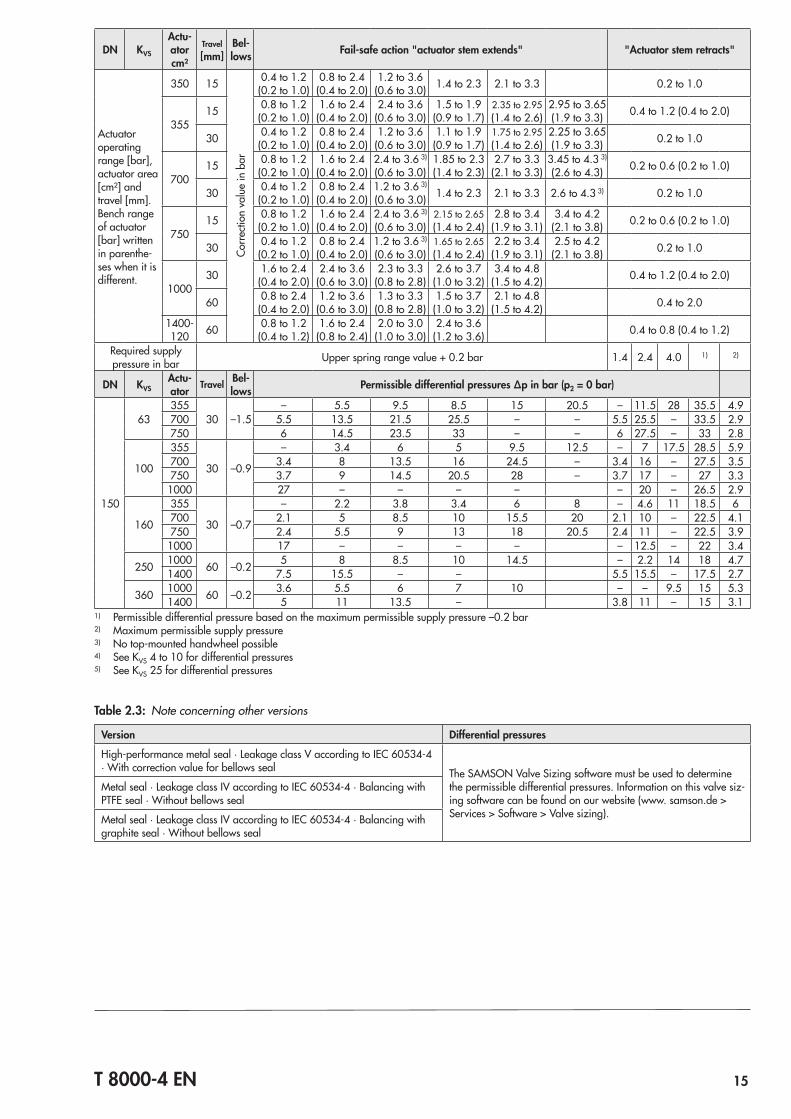
150
63355
30 –1.5– 5.5 9.5 8.5 15 20.5 – 11.5 28 35.5 4.9
700 5.5 13.5 21.5 25.5 – – 5.5 25.5 – 33.5 2.9750 6 14.5 23.5 33 – – 6 27.5 – 33 2.8
100
355
30 –0.9
– 3.4 6 5 9.5 12.5 – 7 17.5 28.5 5.9700 3.4 8 13.5 16 24.5 – 3.4 16 – 27.5 3.5750 3.7 9 14.5 20.5 28 – 3.7 17 – 27 3.3
1000 27 – – – – – 20 – 26.5 2.9
160
355
30 –0.7
– 2.2 3.8 3.4 6 8 – 4.6 11 18.5 6700 2.1 5 8.5 10 15.5 20 2.1 10 – 22.5 4.1750 2.4 5.5 9 13 18 20.5 2.4 11 – 22.5 3.9
1000 17 – – – – – 12.5 – 22 3.4
250 1000 60 –0.2 5 8 8.5 10 14.5 – 2.2 14 18 4.71400 7.5 15.5 – – 5.5 15.5 – 17.5 2.7
360 1000 60 –0.2 3.6 5.5 6 7 10 – – 9.5 15 5.31400 5 11 13.5 – 3.8 11 – 15 3.1
1) Permissible differential pressure based on the maximum permissible supply pressure –0.2 bar2) Maximum permissible supply pressure3) No top‑mounted handwheel possible4) See KVS 4 to 10 for differential pressures5) See KVS 25 for differential pressures
Table 2.3: Note concerning other versions
Version Differential pressures
High‑performance metal seal · Leakage class V according to IEC 60534‑4 · With correction value for bellows seal The SAMSON Valve Sizing software must be used to determine
the permissible differential pressures. Information on this valve siz‑ing software can be found on our website (www. samson.de > Services > Software > Valve sizing).
Metal seal · Leakage class IV according to IEC 60534‑4 · Balancing with PTFE seal · Without bellows seal
Metal seal · Leakage class IV according to IEC 60534‑4 · Balancing with graphite seal · Without bellows seal
16 T 8000-4 EN
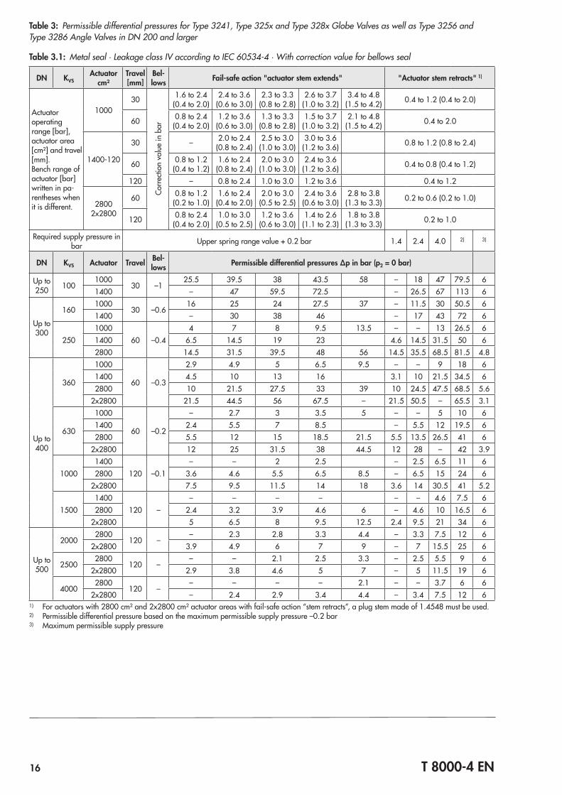
Table 3: Permissible differential pressures for Type 3241, Type 325x and Type 328x Globe Valves as well as Type 3256 and Type 3286 Angle Valves in DN 200 and larger
Table 3.1: Metal seal · Leakage class IV according to IEC 60534‑4 · With correction value for bellows seal
DN KVSActuator
cm²Travel [mm]
Bel-lows Fail-safe action "actuator stem extends" "Actuator stem retracts" 1)
Actuator operating range [bar], actuator area [cm²] and travel [mm].Bench range of actuator [bar] written in pa‑rentheses when it is different.
100030
Corre
ction
val
ue in
bar
1.6 to 2.4(0.4 to 2.0)
2.4 to 3.6(0.6 to 3.0)
2.3 to 3.3(0.8 to 2.8)
2.6 to 3.7(1.0 to 3.2)
3.4 to 4.8(1.5 to 4.2) 0.4 to 1.2 (0.4 to 2.0)
60 0.8 to 2.4(0.4 to 2.0)
1.2 to 3.6(0.6 to 3.0)
1.3 to 3.3(0.8 to 2.8)
1.5 to 3.7(1.0 to 3.2)
2.1 to 4.8(1.5 to 4.2) 0.4 to 2.0
1400‑120
30 – 2.0 to 2.4(0.8 to 2.4)
2.5 to 3.0(1.0 to 3.0)
3.0 to 3.6(1.2 to 3.6) 0.8 to 1.2 (0.8 to 2.4)
60 0.8 to 1.2(0.4 to 1.2)
1.6 to 2.4(0.8 to 2.4)
2.0 to 3.0(1.0 to 3.0)
2.4 to 3.6(1.2 to 3.6) 0.4 to 0.8 (0.4 to 1.2)
120 – 0.8 to 2.4 1.0 to 3.0 1.2 to 3.6 0.4 to 1.2
28002x2800
60 0.8 to 1.2(0.2 to 1.0)
1.6 to 2.4(0.4 to 2.0)
2.0 to 3.0(0.5 to 2.5)
2.4 to 3.6(0.6 to 3.0)
2.8 to 3.8(1.3 to 3.3) 0.2 to 0.6 (0.2 to 1.0)
120 0.8 to 2.4(0.4 to 2.0)
1.0 to 3.0(0.5 to 2.5)
1.2 to 3.6(0.6 to 3.0)
1.4 to 2.6(1.1 to 2.3)
1.8 to 3.8(1.3 to 3.3) 0.2 to 1.0
Required supply pressure in bar Upper spring range value + 0.2 bar 1.4 2.4 4.0 2) 3)
DN KVS Actuator Travel Bel-lows Permissible differential pressures Δp in bar (p2 = 0 bar)
Up to 250 100
100030 –1
25.5 39.5 38 43.5 58 – 18 47 79.5 61400 – 47 59.5 72.5 – 26.5 67 113 6
Up to 300
1601000
30 –0.616 25 24 27.5 37 – 11.5 30 50.5 6
1400 – 30 38 46 – 17 43 72 6
2501000
60 –0.44 7 8 9.5 13.5 – – 13 26.5 6
1400 6.5 14.5 19 23 4.6 14.5 31.5 50 62800 14.5 31.5 39.5 48 56 14.5 35.5 68.5 81.5 4.8
Up to 400
360
1000
60 –0.3
2.9 4.9 5 6.5 9.5 – – 9 18 61400 4.5 10 13 16 3.1 10 21.5 34.5 62800 10 21.5 27.5 33 39 10 24.5 47.5 68.5 5.6
2x2800 21.5 44.5 56 67.5 – 21.5 50.5 – 65.5 3.1
630
1000
60 –0.2
– 2.7 3 3.5 5 – – 5 10 61400 2.4 5.5 7 8.5 – 5.5 12 19.5 62800 5.5 12 15 18.5 21.5 5.5 13.5 26.5 41 6
2x2800 12 25 31.5 38 44.5 12 28 – 42 3.9
10001400
120 –0.1– – 2 2.5 – 2.5 6.5 11 6
2800 3.6 4.6 5.5 6.5 8.5 – 6.5 15 24 62x2800 7.5 9.5 11.5 14 18 3.6 14 30.5 41 5.2
15001400
120 –– – – – – – 4.6 7.5 6
2800 2.4 3.2 3.9 4.6 6 – 4.6 10 16.5 62x2800 5 6.5 8 9.5 12.5 2.4 9.5 21 34 6
Up to 500
20002800
120 –– 2.3 2.8 3.3 4.4 – 3.3 7.5 12 6
2x2800 3.9 4.9 6 7 9 – 7 15.5 25 6
25002800
120 –– – 2.1 2.5 3.3 – 2.5 5.5 9 6
2x2800 2.9 3.8 4.6 5 7 – 5 11.5 19 6
40002800
120 –– – – – 2.1 – – 3.7 6 6
2x2800 – 2.4 2.9 3.4 4.4 – 3.4 7.5 12 61) For actuators with 2800 cm² and 2x2800 cm² actuator areas with fail‑safe action “stem retracts”, a plug stem made of 1.4548 must be used.2) Permissible differential pressure based on the maximum permissible supply pressure –0.2 bar3) Maximum permissible supply pressure
T 8000-4 EN 17
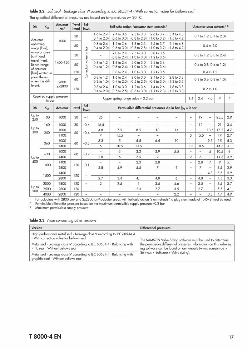
Table 3.2: Soft seal · Leakage class VI according to IEC 60534‑4 · With correction value for bellows sealThe specified differential pressures are based on temperatures >– 20 °C.
DN KVSActuator
cm²Travel [mm]
Bel-lows Fail-safe action "actuator stem extends" "Actuator stem retracts" 1)
Actuator operating range [bar], actuator area [cm²] and travel [mm].Bench range of actuator [bar] written in parentheses when it is dif‑ferent.
100030
Corre
ction
val
ue in
bar
1.6 to 2.4(0.4 to 2.0)
2.4 to 3.6(0.6 to 3.0)
2.3 to 3.3(0.8 to 2.8)
2.6 to 3.7(1.0 to 3.2)
3.4 to 4.8(1.5 to 4.2) 0.4 to 1.2 (0.4 to 2.0)
60 0.8 to 2.4(0.4 to 2.0)
1.2 to 3.6(0.6 to 3.0)
1.3 to 3.3(0.8 to 2.8)
1.5 to 3.7(1.0 to 3.2)
2.1 to 4.8(1.5 to 4.2) 0.4 to 2.0
1400‑120
30 – 2.0 to 2.4(0.8 to 2.4)
2.5 to 3.0(1.0 to 3.0)
3.0 to 3.6(1.2 to 3.6) 0.8 to 1.2 (0.8 to 2.4)
60 0.8 to 1.2(0.4 to 1.2)
1.6 to 2.4(0.8 to 2.4)
2.0 to 3.0(1.0 to 3.0)
2.4 to 3.6(1.2 to 3.6) 0.4 to 0.8 (0.4 to 1.2)
120 – 0.8 to 2.4 1.0 to 3.0 1.2 to 3.6 0.4 to 1.2
28002x2800
60 0.8 to 1.2(0.2 to 1.0)
1.6 to 2.4(0.4 to 2.0)
2.0 to 3.0(0.5 to 2.5)
2.4 to 3.6(0.6 to 3.0)
2.8 to 3.8(1.3 to 3.3) 0.2 to 0.6 (0.2 to 1.0)
120 0.8 to 2.4(0.4 to 2.0)
1.0 to 3.0(0.5 to 2.5)
1.2 to 3.6(0.6 to 3.0)
1.4 to 2.6(1.1 to 2.3)
1.8 to 3.8(1.3 to 3.3) 0.2 to 1.0
Required supply pressure in bar Upper spring range value + 0.2 bar 1.4 2.4 4.0 2) 3)
DN KVS Actuator Travel Bel-lows Permissible differential pressures Δp in bar (p2 = 0 bar)
Up to 250 100 1000 30 –1 26 – – – – – 19 – 25.5 2.9
Up to 300
160 1000 30 –0.6 16.5 – – – – – 12 – 21 3.4
2501000
60 –0.44.8 7.5 8.5 10 14 – – 13.5 17.5 4.7
1400 7 15.5 – – 5 15.5 – 17 2.7
Up to 400
3601000
60 –0.33.3 5 5.5 6.5 10 – – 9.5 15 5.3
1400 5 10.5 13.5 – 3.5 10.5 – 14.5 3.1
6301000
60 –0.2– 3 3.3 3.9 5.5 – – 5 10.5 6
1400 2.8 6 7.5 9 2 6 – 11.5 3.9
10001400
120 –0.1– – 2.3 2.8 – 2.8 7 9 5.1
2800 3.8 4.9 5.5 7 9 – 7 – 8.5 2.9
15001400
120 –– – – – – – 4.8 7.5 5.9
2800 2.7 3.4 4.1 4.8 6 – 4.8 – 7.5 3.3
Up to 500
2000 2800 120 – 2 2.5 3 3.5 4.6 – 3.5 – 6.5 3.72500 2800 120 – – – 2.3 2.7 3.5 – 2.7 – 5.5 4.14000 2800 120 – – – – – 2.2 – – 3.8 4.7 4.9
1) For actuators with 2800 cm² and 2x2800 cm² actuator areas with fail‑safe action “stem retracts”, a plug stem made of 1.4548 must be used.2) Permissible differential pressure based on the maximum permissible supply pressure –0.2 bar3) Maximum permissible supply pressure
Table 3.3: Note concerning other versions
Version Differential pressures
High‑performance metal seal · Leakage class V according to IEC 60534‑4 · With correction value for bellows seal The SAMSON Valve Sizing software must be used to determine
the permissible differential pressures. Information on this valve siz‑ing software can be found on our website (www. samson.de > Services > Software > Valve sizing).
Metal seal · Leakage class IV according to IEC 60534‑4 · Balancing with PTFE seal · Without bellows seal
Metal seal · Leakage class IV according to IEC 60534‑4 · Balancing with graphite seal · Without bellows seal
18 T 8000-4 EN
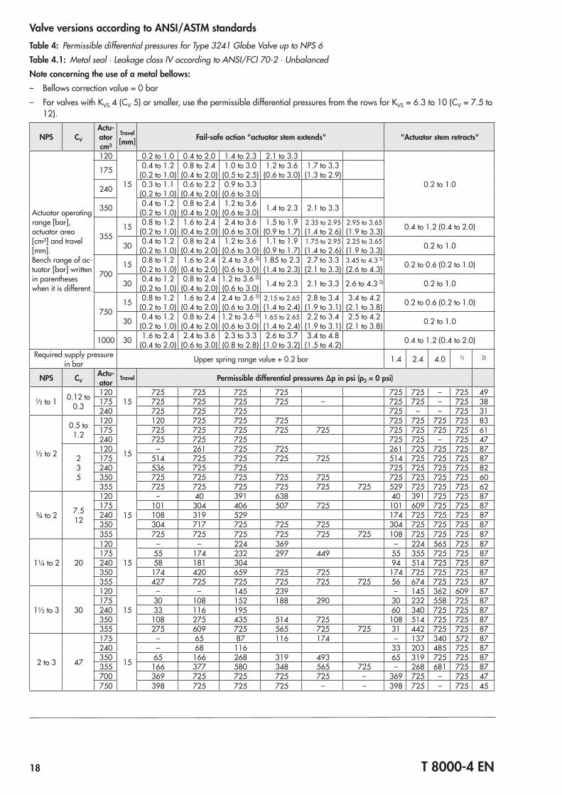
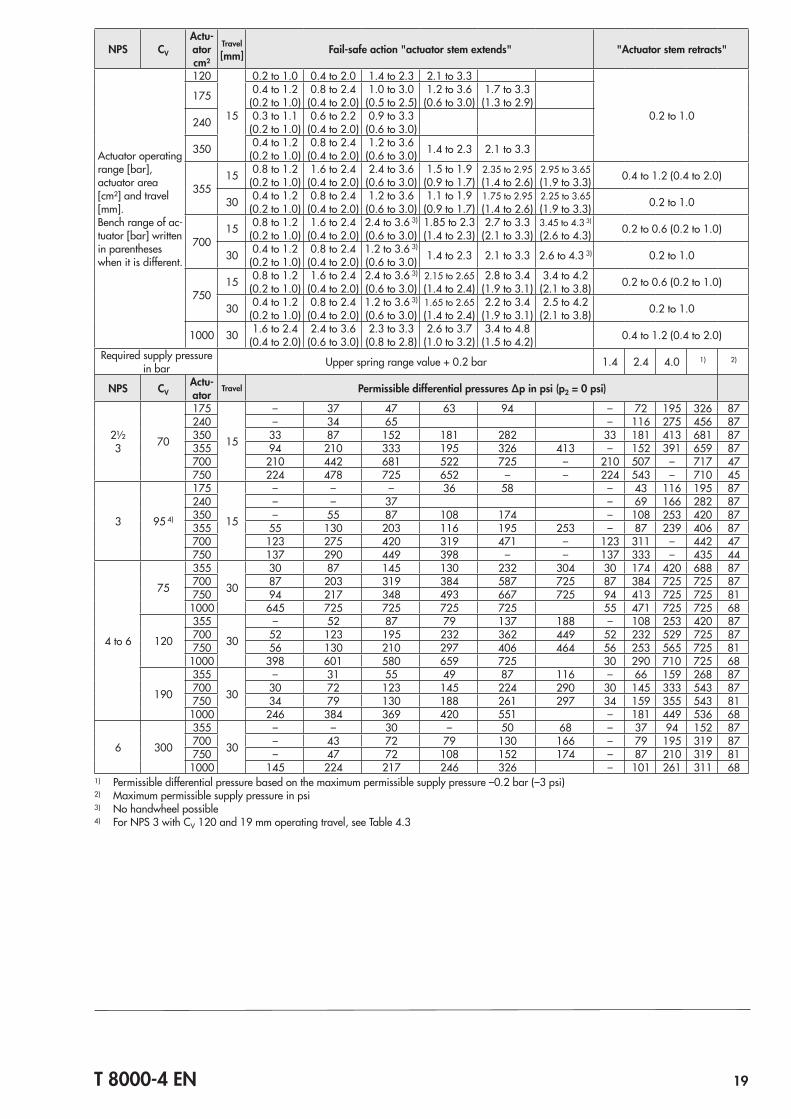
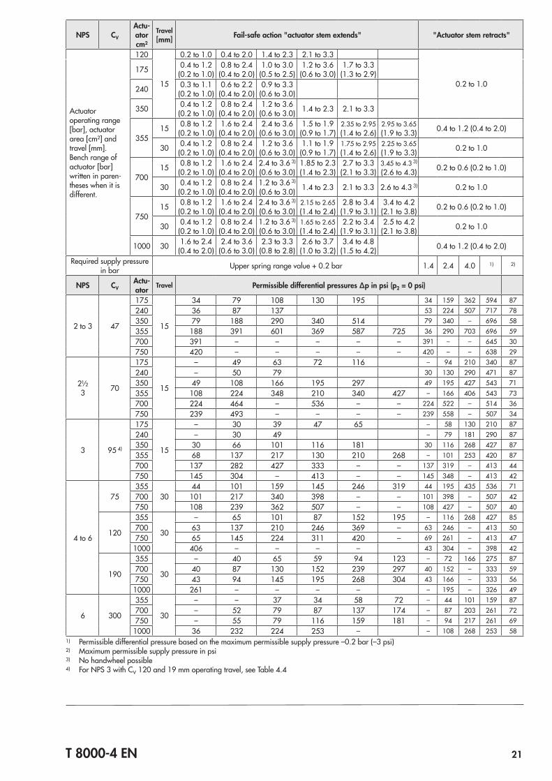
Valve versions according to ANSI/ASTM standardsTable 4: Permissible differential pressures for Type 3241 Globe Valve up to NPS 6Table 4.1: Metal seal · Leakage class IV according to ANSI/FCI 70‑2 · UnbalancedNote concerning the use of a metal bellows: – Bellows correction value = 0 bar – For valves with KVS 4 (CV 5) or smaller, use the permissible differential pressures from the rows for KVS = 6.3 to 10 (CV = 7.5 to
12).
NPS CV
Actu-ator cm²
Travel [mm] Fail-safe action "actuator stem extends" "Actuator stem retracts"
Actuator operating range [bar], actuator area [cm²] and travel [mm].Bench range of ac‑tuator [bar] written in parentheses when it is different.
120
15
0.2 to 1.0 0.4 to 2.0 1.4 to 2.3 2.1 to 3.3
0.2 to 1.0
175 0.4 to 1.2(0.2 to 1.0)
0.8 to 2.4(0.4 to 2.0)
1.0 to 3.0(0.5 to 2.5)
1.2 to 3.6(0.6 to 3.0)
1.7 to 3.3(1.3 to 2.9)
240 0.3 to 1.1(0.2 to 1.0)
0.6 to 2.2(0.4 to 2.0)
0.9 to 3.3(0.6 to 3.0)
350 0.4 to 1.2(0.2 to 1.0)
0.8 to 2.4(0.4 to 2.0)
1.2 to 3.6(0.6 to 3.0) 1.4 to 2.3 2.1 to 3.3
35515 0.8 to 1.2
(0.2 to 1.0)1.6 to 2.4
(0.4 to 2.0)2.4 to 3.6
(0.6 to 3.0)1.5 to 1.9
(0.9 to 1.7)2.35 to 2.95(1.4 to 2.6)
2.95 to 3.65(1.9 to 3.3) 0.4 to 1.2 (0.4 to 2.0)
30 0.4 to 1.2(0.2 to 1.0)
0.8 to 2.4(0.4 to 2.0)
1.2 to 3.6(0.6 to 3.0)
1.1 to 1.9(0.9 to 1.7)
1.75 to 2.95(1.4 to 2.6)
2.25 to 3.65(1.9 to 3.3) 0.2 to 1.0
70015 0.8 to 1.2
(0.2 to 1.0)1.6 to 2.4
(0.4 to 2.0)2.4 to 3.6 3)
(0.6 to 3.0)1.85 to 2.3(1.4 to 2.3)
2.7 to 3.3(2.1 to 3.3)
3.45 to 4.3 3)
(2.6 to 4.3) 0.2 to 0.6 (0.2 to 1.0)
30 0.4 to 1.2(0.2 to 1.0)
0.8 to 2.4(0.4 to 2.0)
1.2 to 3.6 3)
(0.6 to 3.0) 1.4 to 2.3 2.1 to 3.3 2.6 to 4.3 3) 0.2 to 1.0
75015 0.8 to 1.2
(0.2 to 1.0)1.6 to 2.4
(0.4 to 2.0)2.4 to 3.6 3)
(0.6 to 3.0)2.15 to 2.65(1.4 to 2.4)
2.8 to 3.4(1.9 to 3.1)
3.4 to 4.2(2.1 to 3.8) 0.2 to 0.6 (0.2 to 1.0)
30 0.4 to 1.2(0.2 to 1.0)
0.8 to 2.4(0.4 to 2.0)
1.2 to 3.6 3)
(0.6 to 3.0)1.65 to 2.65(1.4 to 2.4)
2.2 to 3.4(1.9 to 3.1)
2.5 to 4.2(2.1 to 3.8) 0.2 to 1.0
1000 30 1.6 to 2.4(0.4 to 2.0)
2.4 to 3.6(0.6 to 3.0)
2.3 to 3.3(0.8 to 2.8)
2.6 to 3.7(1.0 to 3.2)
3.4 to 4.8(1.5 to 4.2) 0.4 to 1.2 (0.4 to 2.0)
Required supply pressure in bar Upper spring range value + 0.2 bar 1.4 2.4 4.0 1) 2)
NPS CVActu-ator
Travel Permissible differential pressures Δp in psi (p2 = 0 psi)
½ to 1 0.12 to 0.3
12015
725 725 725 725 725 725 – 725 49175 725 725 725 725 – 725 725 – 725 38240 725 725 725 725 – – 725 31
½ to 2
0.5 to 1.2
120
15
120 725 725 725 725 725 725 725 83175 725 725 725 725 725 725 725 725 725 61240 725 725 725 725 725 – 725 47
235
120 – 261 725 725 261 725 725 725 87175 514 725 725 725 725 514 725 725 725 87240 536 725 725 725 725 725 725 82350 725 725 725 725 725 725 725 725 725 60355 725 725 725 725 725 725 529 725 725 725 62
¾ to 2 7.512
120
15
– 40 391 638 40 391 725 725 87175 101 304 406 507 725 101 609 725 725 87240 108 319 529 174 725 725 725 87350 304 717 725 725 725 304 725 725 725 87355 725 725 725 725 725 725 108 725 725 725 87
1¼ to 2 20
120
15
– – 224 369 – 224 565 725 87175 55 174 232 297 449 55 355 725 725 87240 58 181 304 94 514 725 725 87350 174 420 659 725 725 174 725 725 725 87355 427 725 725 725 725 725 56 674 725 725 87
1½ to 3 30
120
15
– – 145 239 – 145 362 609 87175 30 108 152 188 290 30 232 558 725 87240 33 116 195 60 340 725 725 87350 108 275 435 514 725 108 514 725 725 87355 275 609 725 565 725 725 31 442 725 725 87
2 to 3 47
175
15
– 65 87 116 174 – 137 340 572 87240 – 68 116 33 203 485 725 87350 65 166 268 319 493 65 319 725 725 87355 166 377 580 348 565 725 – 268 681 725 87700 369 725 725 725 725 – 369 725 – 725 47750 398 725 725 725 – – 398 725 – 725 45
T 8000-4 EN 19
NPS CV
Actu-ator cm²
Travel [mm] Fail-safe action "actuator stem extends" "Actuator stem retracts"
Actuator operating range [bar], actuator area [cm²] and travel [mm].Bench range of ac‑tuator [bar] written in parentheses when it is different.
120
15
0.2 to 1.0 0.4 to 2.0 1.4 to 2.3 2.1 to 3.3
0.2 to 1.0
175 0.4 to 1.2(0.2 to 1.0)
0.8 to 2.4(0.4 to 2.0)
1.0 to 3.0(0.5 to 2.5)
1.2 to 3.6(0.6 to 3.0)
1.7 to 3.3(1.3 to 2.9)
240 0.3 to 1.1(0.2 to 1.0)
0.6 to 2.2(0.4 to 2.0)
0.9 to 3.3(0.6 to 3.0)
350 0.4 to 1.2(0.2 to 1.0)
0.8 to 2.4(0.4 to 2.0)
1.2 to 3.6(0.6 to 3.0) 1.4 to 2.3 2.1 to 3.3
35515 0.8 to 1.2
(0.2 to 1.0)1.6 to 2.4
(0.4 to 2.0)2.4 to 3.6
(0.6 to 3.0)1.5 to 1.9
(0.9 to 1.7)2.35 to 2.95(1.4 to 2.6)
2.95 to 3.65(1.9 to 3.3) 0.4 to 1.2 (0.4 to 2.0)
30 0.4 to 1.2(0.2 to 1.0)
0.8 to 2.4(0.4 to 2.0)
1.2 to 3.6(0.6 to 3.0)
1.1 to 1.9(0.9 to 1.7)
1.75 to 2.95(1.4 to 2.6)
2.25 to 3.65(1.9 to 3.3) 0.2 to 1.0
70015 0.8 to 1.2
(0.2 to 1.0)1.6 to 2.4
(0.4 to 2.0)2.4 to 3.6 3)
(0.6 to 3.0)1.85 to 2.3(1.4 to 2.3)
2.7 to 3.3(2.1 to 3.3)
3.45 to 4.3 3)
(2.6 to 4.3) 0.2 to 0.6 (0.2 to 1.0)
30 0.4 to 1.2(0.2 to 1.0)
0.8 to 2.4(0.4 to 2.0)
1.2 to 3.6 3)
(0.6 to 3.0) 1.4 to 2.3 2.1 to 3.3 2.6 to 4.3 3) 0.2 to 1.0
75015 0.8 to 1.2
(0.2 to 1.0)1.6 to 2.4
(0.4 to 2.0)2.4 to 3.6 3)
(0.6 to 3.0)2.15 to 2.65(1.4 to 2.4)
2.8 to 3.4(1.9 to 3.1)
3.4 to 4.2(2.1 to 3.8) 0.2 to 0.6 (0.2 to 1.0)
30 0.4 to 1.2(0.2 to 1.0)
0.8 to 2.4(0.4 to 2.0)
1.2 to 3.6 3)
(0.6 to 3.0)1.65 to 2.65(1.4 to 2.4)
2.2 to 3.4(1.9 to 3.1)
2.5 to 4.2(2.1 to 3.8) 0.2 to 1.0
1000 30 1.6 to 2.4(0.4 to 2.0)
2.4 to 3.6(0.6 to 3.0)
2.3 to 3.3(0.8 to 2.8)
2.6 to 3.7(1.0 to 3.2)
3.4 to 4.8(1.5 to 4.2) 0.4 to 1.2 (0.4 to 2.0)
Required supply pressure in bar Upper spring range value + 0.2 bar 1.4 2.4 4.0 1) 2)
NPS CVActu-ator
Travel Permissible differential pressures Δp in psi (p2 = 0 psi)
2½3 70
175
15
– 37 47 63 94 – 72 195 326 87240 – 34 65 – 116 275 456 87350 33 87 152 181 282 33 181 413 681 87355 94 210 333 195 326 413 – 152 391 659 87700 210 442 681 522 725 – 210 507 – 717 47750 224 478 725 652 – – 224 543 – 710 45
3 95 4)
175
15
– – – 36 58 – 43 116 195 87240 – – 37 – 69 166 282 87350 – 55 87 108 174 – 108 253 420 87355 55 130 203 116 195 253 – 87 239 406 87700 123 275 420 319 471 – 123 311 – 442 47750 137 290 449 398 – – 137 333 – 435 44
4 to 6
75
355
30
30 87 145 130 232 304 30 174 420 688 87700 87 203 319 384 587 725 87 384 725 725 87750 94 217 348 493 667 725 94 413 725 725 811000 645 725 725 725 725 55 471 725 725 68
120
355
30
– 52 87 79 137 188 – 108 253 420 87700 52 123 195 232 362 449 52 232 529 725 87750 56 130 210 297 406 464 56 253 565 725 81
1000 398 601 580 659 725 30 290 710 725 68
190
355
30
– 31 55 49 87 116 – 66 159 268 87700 30 72 123 145 224 290 30 145 333 543 87750 34 79 130 188 261 297 34 159 355 543 811000 246 384 369 420 551 – 181 449 536 68
6 300
355
30
– – 30 – 50 68 – 37 94 152 87700 – 43 72 79 130 166 – 79 195 319 87750 – 47 72 108 152 174 – 87 210 319 811000 145 224 217 246 326 – 101 261 311 68
1) Permissible differential pressure based on the maximum permissible supply pressure –0.2 bar (–3 psi)2) Maximum permissible supply pressure in psi3) No handwheel possible4) For NPS 3 with CV 120 and 19 mm operating travel, see Table 4.3
20 T 8000-4 EN
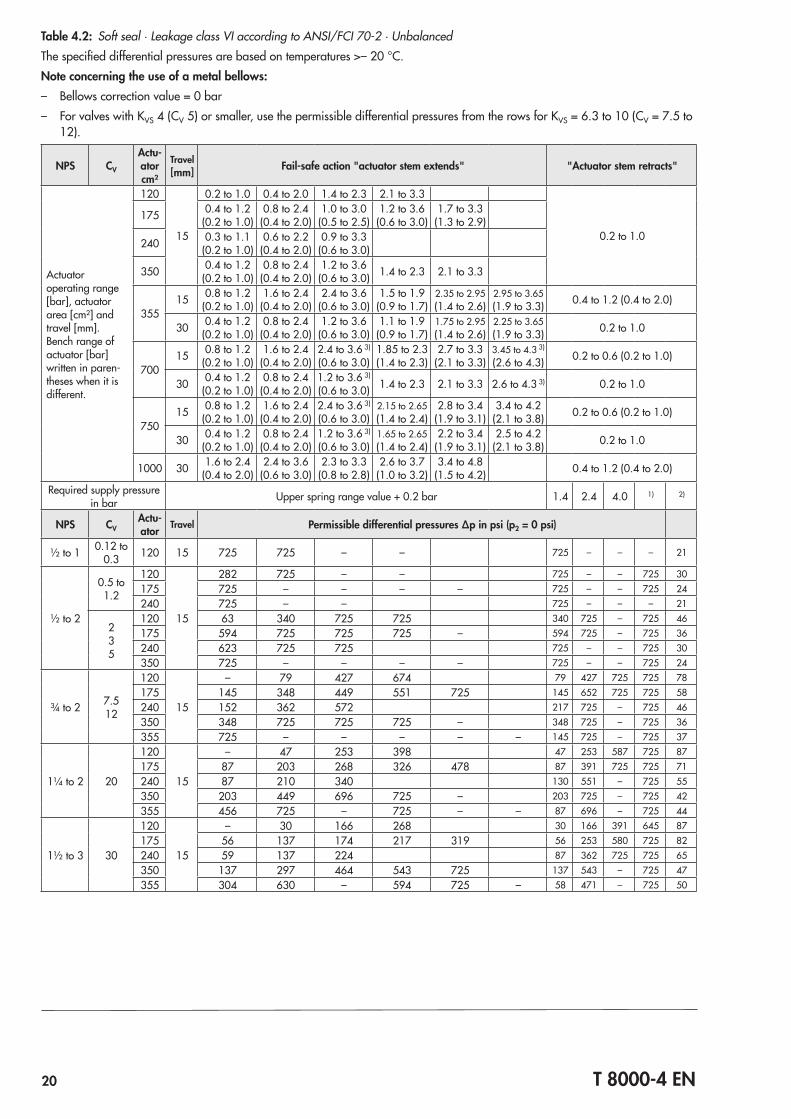
Table 4.2: Soft seal · Leakage class VI according to ANSI/FCI 70‑2 · UnbalancedThe specified differential pressures are based on temperatures >– 20 °C.Note concerning the use of a metal bellows: – Bellows correction value = 0 bar – For valves with KVS 4 (CV 5) or smaller, use the permissible differential pressures from the rows for KVS = 6.3 to 10 (CV = 7.5 to
12).
NPS CV
Actu-ator cm²
Travel [mm] Fail-safe action "actuator stem extends" "Actuator stem retracts"
Actuator operating range [bar], actuator area [cm²] and travel [mm].Bench range of actuator [bar] written in paren‑theses when it is different.
120
15
0.2 to 1.0 0.4 to 2.0 1.4 to 2.3 2.1 to 3.3
0.2 to 1.0
175 0.4 to 1.2(0.2 to 1.0)
0.8 to 2.4(0.4 to 2.0)
1.0 to 3.0(0.5 to 2.5)
1.2 to 3.6(0.6 to 3.0)
1.7 to 3.3(1.3 to 2.9)
240 0.3 to 1.1(0.2 to 1.0)
0.6 to 2.2(0.4 to 2.0)
0.9 to 3.3(0.6 to 3.0)
350 0.4 to 1.2(0.2 to 1.0)
0.8 to 2.4(0.4 to 2.0)
1.2 to 3.6(0.6 to 3.0) 1.4 to 2.3 2.1 to 3.3
35515 0.8 to 1.2
(0.2 to 1.0)1.6 to 2.4
(0.4 to 2.0)2.4 to 3.6
(0.6 to 3.0)1.5 to 1.9
(0.9 to 1.7)2.35 to 2.95(1.4 to 2.6)
2.95 to 3.65(1.9 to 3.3) 0.4 to 1.2 (0.4 to 2.0)
30 0.4 to 1.2(0.2 to 1.0)
0.8 to 2.4(0.4 to 2.0)
1.2 to 3.6(0.6 to 3.0)
1.1 to 1.9(0.9 to 1.7)
1.75 to 2.95(1.4 to 2.6)
2.25 to 3.65(1.9 to 3.3) 0.2 to 1.0
70015 0.8 to 1.2
(0.2 to 1.0)1.6 to 2.4
(0.4 to 2.0)2.4 to 3.6 3)
(0.6 to 3.0)1.85 to 2.3(1.4 to 2.3)
2.7 to 3.3(2.1 to 3.3)
3.45 to 4.3 3)
(2.6 to 4.3) 0.2 to 0.6 (0.2 to 1.0)
30 0.4 to 1.2(0.2 to 1.0)
0.8 to 2.4(0.4 to 2.0)
1.2 to 3.6 3)
(0.6 to 3.0) 1.4 to 2.3 2.1 to 3.3 2.6 to 4.3 3) 0.2 to 1.0
75015 0.8 to 1.2
(0.2 to 1.0)1.6 to 2.4
(0.4 to 2.0)2.4 to 3.6 3)
(0.6 to 3.0)2.15 to 2.65(1.4 to 2.4)
2.8 to 3.4(1.9 to 3.1)
3.4 to 4.2(2.1 to 3.8) 0.2 to 0.6 (0.2 to 1.0)
30 0.4 to 1.2(0.2 to 1.0)
0.8 to 2.4(0.4 to 2.0)
1.2 to 3.6 3)
(0.6 to 3.0)1.65 to 2.65(1.4 to 2.4)
2.2 to 3.4(1.9 to 3.1)
2.5 to 4.2(2.1 to 3.8) 0.2 to 1.0
1000 30 1.6 to 2.4(0.4 to 2.0)
2.4 to 3.6(0.6 to 3.0)
2.3 to 3.3(0.8 to 2.8)
2.6 to 3.7(1.0 to 3.2)
3.4 to 4.8(1.5 to 4.2) 0.4 to 1.2 (0.4 to 2.0)
Required supply pressure in bar Upper spring range value + 0.2 bar 1.4 2.4 4.0 1) 2)
NPS CVActu-ator Travel Permissible differential pressures Δp in psi (p2 = 0 psi)
½ to 1 0.12 to 0.3 120 15 725 725 – – 725 – – – 21
½ to 2
0.5 to 1.2
120
15
282 725 – – 725 – – 725 30175 725 – – – – 725 – – 725 24240 725 – – 725 – – – 21
235
120 63 340 725 725 340 725 – 725 46175 594 725 725 725 – 594 725 – 725 36240 623 725 725 725 – – 725 30350 725 – – – – 725 – – 725 24
¾ to 2 7.512
120
15
– 79 427 674 79 427 725 725 78175 145 348 449 551 725 145 652 725 725 58240 152 362 572 217 725 – 725 46350 348 725 725 725 – 348 725 – 725 36355 725 – – – – – 145 725 – 725 37
1¼ to 2 20
120
15
– 47 253 398 47 253 587 725 87175 87 203 268 326 478 87 391 725 725 71240 87 210 340 130 551 – 725 55350 203 449 696 725 – 203 725 – 725 42355 456 725 – 725 – – 87 696 – 725 44
1½ to 3 30
120
15
– 30 166 268 30 166 391 645 87175 56 137 174 217 319 56 253 580 725 82240 59 137 224 87 362 725 725 65350 137 297 464 543 725 137 543 – 725 47355 304 630 – 594 725 – 58 471 – 725 50
T 8000-4 EN 21
NPS CV
Actu-ator cm²
Travel [mm] Fail-safe action "actuator stem extends" "Actuator stem retracts"
Actuator operating range [bar], actuator area [cm²] and travel [mm].Bench range of actuator [bar] written in paren‑theses when it is different.
120
15
0.2 to 1.0 0.4 to 2.0 1.4 to 2.3 2.1 to 3.3
0.2 to 1.0
175 0.4 to 1.2(0.2 to 1.0)
0.8 to 2.4(0.4 to 2.0)
1.0 to 3.0(0.5 to 2.5)
1.2 to 3.6(0.6 to 3.0)
1.7 to 3.3(1.3 to 2.9)
240 0.3 to 1.1(0.2 to 1.0)
0.6 to 2.2(0.4 to 2.0)
0.9 to 3.3(0.6 to 3.0)
350 0.4 to 1.2(0.2 to 1.0)
0.8 to 2.4(0.4 to 2.0)
1.2 to 3.6(0.6 to 3.0) 1.4 to 2.3 2.1 to 3.3
35515 0.8 to 1.2
(0.2 to 1.0)1.6 to 2.4
(0.4 to 2.0)2.4 to 3.6
(0.6 to 3.0)1.5 to 1.9
(0.9 to 1.7)2.35 to 2.95(1.4 to 2.6)
2.95 to 3.65(1.9 to 3.3) 0.4 to 1.2 (0.4 to 2.0)
30 0.4 to 1.2(0.2 to 1.0)
0.8 to 2.4(0.4 to 2.0)
1.2 to 3.6(0.6 to 3.0)
1.1 to 1.9(0.9 to 1.7)
1.75 to 2.95(1.4 to 2.6)
2.25 to 3.65(1.9 to 3.3) 0.2 to 1.0
70015 0.8 to 1.2
(0.2 to 1.0)1.6 to 2.4
(0.4 to 2.0)2.4 to 3.6 3)
(0.6 to 3.0)1.85 to 2.3(1.4 to 2.3)
2.7 to 3.3(2.1 to 3.3)
3.45 to 4.3 3)
(2.6 to 4.3) 0.2 to 0.6 (0.2 to 1.0)
30 0.4 to 1.2(0.2 to 1.0)
0.8 to 2.4(0.4 to 2.0)
1.2 to 3.6 3)
(0.6 to 3.0) 1.4 to 2.3 2.1 to 3.3 2.6 to 4.3 3) 0.2 to 1.0
75015 0.8 to 1.2
(0.2 to 1.0)1.6 to 2.4
(0.4 to 2.0)2.4 to 3.6 3)
(0.6 to 3.0)2.15 to 2.65(1.4 to 2.4)
2.8 to 3.4(1.9 to 3.1)
3.4 to 4.2(2.1 to 3.8) 0.2 to 0.6 (0.2 to 1.0)
30 0.4 to 1.2(0.2 to 1.0)
0.8 to 2.4(0.4 to 2.0)
1.2 to 3.6 3)
(0.6 to 3.0)1.65 to 2.65(1.4 to 2.4)
2.2 to 3.4(1.9 to 3.1)
2.5 to 4.2(2.1 to 3.8) 0.2 to 1.0
1000 30 1.6 to 2.4(0.4 to 2.0)
2.4 to 3.6(0.6 to 3.0)
2.3 to 3.3(0.8 to 2.8)
2.6 to 3.7(1.0 to 3.2)
3.4 to 4.8(1.5 to 4.2) 0.4 to 1.2 (0.4 to 2.0)
Required supply pressure in bar Upper spring range value + 0.2 bar 1.4 2.4 4.0 1) 2)
NPS CVActu-ator Travel Permissible differential pressures Δp in psi (p2 = 0 psi)
2 to 3 47
175
15
34 79 108 130 195 34 159 362 594 87240 36 87 137 53 224 507 717 78350 79 188 290 340 514 79 340 – 696 58355 188 391 601 369 587 725 36 290 703 696 59700 391 – – – – – 391 – – 645 30750 420 – – – – – 420 – – 638 29
2½3 70
175
15
– 49 63 72 116 – 94 210 340 87240 – 50 79 30 130 290 471 87350 49 108 166 195 297 49 195 427 543 71355 108 224 348 210 340 427 – 166 406 543 73700 224 464 – 536 – – 224 522 – 514 36750 239 493 – – – – 239 558 – 507 34
3 95 4)
175
15
– 30 39 47 65 – 58 130 210 87240 – 30 49 – 79 181 290 87350 30 66 101 116 181 30 116 268 427 87355 68 137 217 130 210 268 – 101 253 420 87700 137 282 427 333 – – 137 319 – 413 44750 145 304 – 413 – – 145 348 – 413 42
4 to 6
75355
3044 101 159 145 246 319 44 195 435 536 71
700 101 217 340 398 – – 101 398 – 507 42750 108 239 362 507 – – 108 427 – 507 40
120
355
30
– 65 101 87 152 195 – 116 268 427 85700 63 137 210 246 369 – 63 246 – 413 50750 65 145 224 311 420 – 69 261 – 413 47
1000 406 – – – – 43 304 – 398 42
190
355
30
– 40 65 59 94 123 – 72 166 275 87700 40 87 130 152 239 297 40 152 – 333 59750 43 94 145 195 268 304 43 166 – 333 56
1000 261 – – – – – 195 – 326 49
6 300
355
30
– – 37 34 58 72 – 44 101 159 87700 – 52 79 87 137 174 – 87 203 261 72750 – 55 79 116 159 181 – 94 217 261 69
1000 36 232 224 253 – – 108 268 253 581) Permissible differential pressure based on the maximum permissible supply pressure –0.2 bar (–3 psi)2) Maximum permissible supply pressure in psi3) No handwheel possible4) For NPS 3 with CV 120 and 19 mm operating travel, see Table 4.4
22 T 8000-4 EN
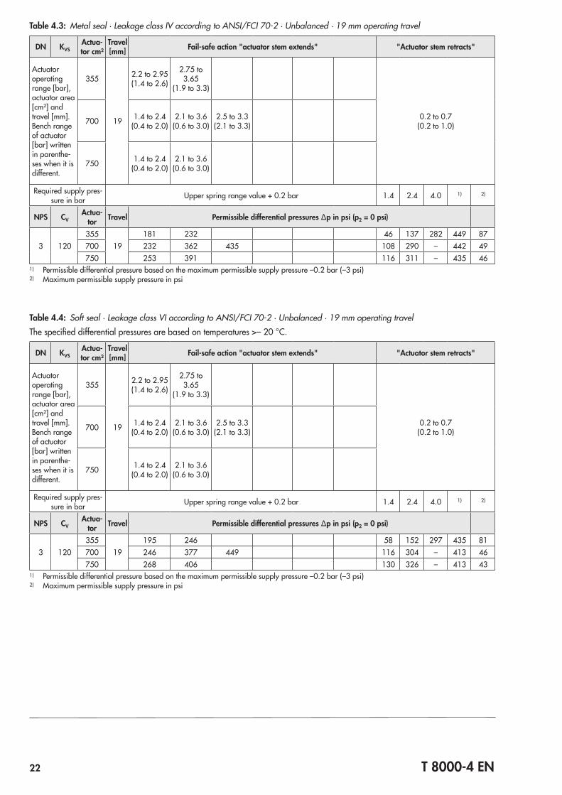
Table 4.3: Metal seal · Leakage class IV according to ANSI/FCI 70‑2 · Unbalanced · 19 mm operating travel
DN KVSActua-tor cm²
Travel [mm] Fail-safe action "actuator stem extends" "Actuator stem retracts"
Actuator operating range [bar], actuator area [cm²] and travel [mm].Bench range of actuator [bar] written in parenthe‑ses when it is different.
355
19
2.2 to 2.95(1.4 to 2.6)
2.75 to 3.65
(1.9 to 3.3)
0.2 to 0.7(0.2 to 1.0)700 1.4 to 2.4
(0.4 to 2.0)2.1 to 3.6
(0.6 to 3.0)2.5 to 3.3
(2.1 to 3.3)
750 1.4 to 2.4(0.4 to 2.0)
2.1 to 3.6(0.6 to 3.0)
Required supply pres‑sure in bar Upper spring range value + 0.2 bar 1.4 2.4 4.0 1) 2)
NPS CVActua-
tor Travel Permissible differential pressures Δp in psi (p2 = 0 psi)
3 120355
19181 232 46 137 282 449 87
700 232 362 435 108 290 – 442 49750 253 391 116 311 – 435 46
1) Permissible differential pressure based on the maximum permissible supply pressure –0.2 bar (–3 psi)2) Maximum permissible supply pressure in psi
Table 4.4: Soft seal · Leakage class VI according to ANSI/FCI 70‑2 · Unbalanced · 19 mm operating travelThe specified differential pressures are based on temperatures >– 20 °C.
DN KVSActua-tor cm²
Travel [mm] Fail-safe action "actuator stem extends" "Actuator stem retracts"
Actuator operating range [bar], actuator area [cm²] and travel [mm].Bench range of actuator [bar] written in parenthe‑ses when it is different.
355
19
2.2 to 2.95(1.4 to 2.6)
2.75 to 3.65
(1.9 to 3.3)
0.2 to 0.7(0.2 to 1.0)700 1.4 to 2.4
(0.4 to 2.0)2.1 to 3.6
(0.6 to 3.0)2.5 to 3.3
(2.1 to 3.3)
750 1.4 to 2.4(0.4 to 2.0)
2.1 to 3.6(0.6 to 3.0)
Required supply pres‑sure in bar Upper spring range value + 0.2 bar 1.4 2.4 4.0 1) 2)
NPS CVActua-
tor Travel Permissible differential pressures Δp in psi (p2 = 0 psi)
3 120355
19195 246 58 152 297 435 81
700 246 377 449 116 304 – 413 46750 268 406 130 326 – 413 43
1) Permissible differential pressure based on the maximum permissible supply pressure –0.2 bar (–3 psi)2) Maximum permissible supply pressure in psi
T 8000-4 EN 23
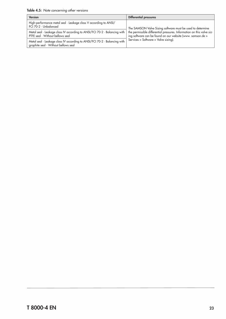
Table 4.5: Note concerning other versions
Version Differential pressures
High‑performance metal seal · Leakage class V according to ANSI/FCI 70‑2 · Unbalanced The SAMSON Valve Sizing software must be used to determine
the permissible differential pressures. Information on this valve siz‑ing software can be found on our website (www. samson.de > Services > Software > Valve sizing).
Metal seal · Leakage class IV according to ANSI/FCI 70‑2 · Balancing with PTFE seal · Without bellows seal
Metal seal · Leakage class IV according to ANSI/FCI 70‑2 · Balancing with graphite seal · Without bellows seal
24 T 8000-4 EN
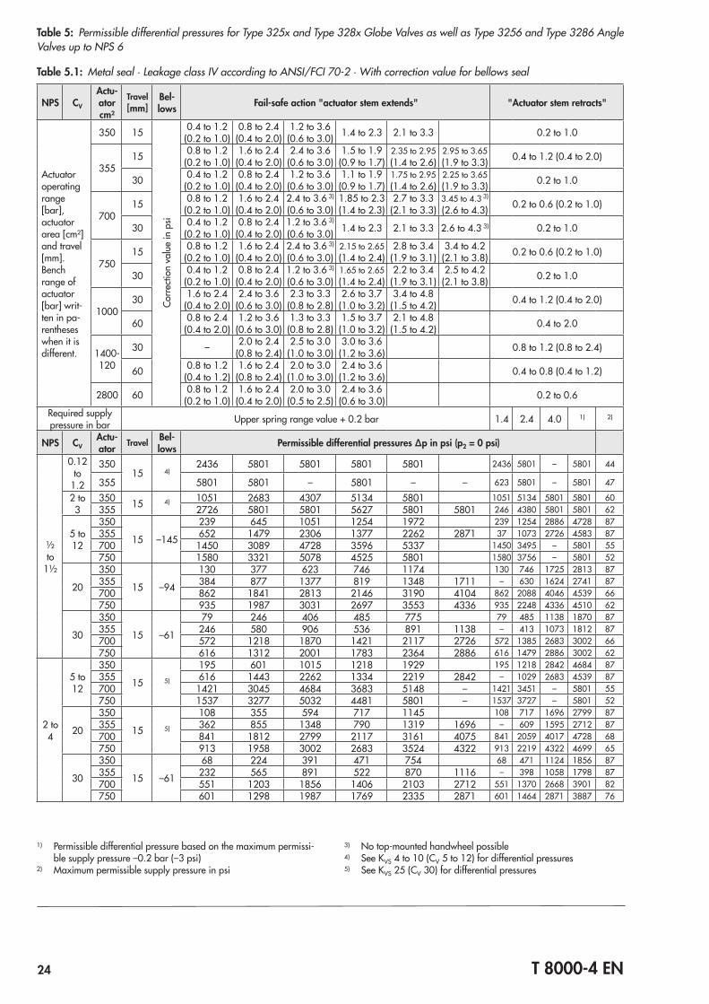
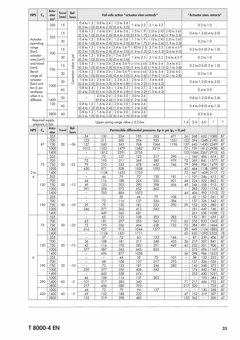
Table 5: Permissible differential pressures for Type 325x and Type 328x Globe Valves as well as Type 3256 and Type 3286 Angle Valves up to NPS 6
Table 5.1: Metal seal · Leakage class IV according to ANSI/FCI 70‑2 · With correction value for bellows seal
NPS CV
Actu-ator cm²
Travel [mm]
Bel-lows Fail-safe action "actuator stem extends" "Actuator stem retracts"
Actuator operating range [bar], actuator area [cm²] and travel [mm].Bench range of actuator [bar] writ‑ten in pa‑rentheses when it is different.
350 15
Corre
ction
val
ue in
psi
0.4 to 1.2(0.2 to 1.0)
0.8 to 2.4(0.4 to 2.0)
1.2 to 3.6(0.6 to 3.0) 1.4 to 2.3 2.1 to 3.3 0.2 to 1.0
35515 0.8 to 1.2
(0.2 to 1.0)1.6 to 2.4
(0.4 to 2.0)2.4 to 3.6
(0.6 to 3.0)1.5 to 1.9
(0.9 to 1.7)2.35 to 2.95(1.4 to 2.6)
2.95 to 3.65(1.9 to 3.3) 0.4 to 1.2 (0.4 to 2.0)
30 0.4 to 1.2(0.2 to 1.0)
0.8 to 2.4(0.4 to 2.0)
1.2 to 3.6(0.6 to 3.0)
1.1 to 1.9(0.9 to 1.7)
1.75 to 2.95(1.4 to 2.6)
2.25 to 3.65(1.9 to 3.3) 0.2 to 1.0
70015 0.8 to 1.2
(0.2 to 1.0)1.6 to 2.4
(0.4 to 2.0)2.4 to 3.6 3)
(0.6 to 3.0)1.85 to 2.3(1.4 to 2.3)
2.7 to 3.3(2.1 to 3.3)
3.45 to 4.3 3)
(2.6 to 4.3) 0.2 to 0.6 (0.2 to 1.0)
30 0.4 to 1.2(0.2 to 1.0)
0.8 to 2.4(0.4 to 2.0)
1.2 to 3.6 3)
(0.6 to 3.0) 1.4 to 2.3 2.1 to 3.3 2.6 to 4.3 3) 0.2 to 1.0
75015 0.8 to 1.2
(0.2 to 1.0)1.6 to 2.4
(0.4 to 2.0)2.4 to 3.6 3)
(0.6 to 3.0)2.15 to 2.65(1.4 to 2.4)
2.8 to 3.4(1.9 to 3.1)
3.4 to 4.2(2.1 to 3.8) 0.2 to 0.6 (0.2 to 1.0)
30 0.4 to 1.2(0.2 to 1.0)
0.8 to 2.4(0.4 to 2.0)
1.2 to 3.6 3)
(0.6 to 3.0)1.65 to 2.65(1.4 to 2.4)
2.2 to 3.4(1.9 to 3.1)
2.5 to 4.2(2.1 to 3.8) 0.2 to 1.0
100030 1.6 to 2.4
(0.4 to 2.0)2.4 to 3.6
(0.6 to 3.0)2.3 to 3.3
(0.8 to 2.8)2.6 to 3.7
(1.0 to 3.2)3.4 to 4.8
(1.5 to 4.2) 0.4 to 1.2 (0.4 to 2.0)
60 0.8 to 2.4(0.4 to 2.0)
1.2 to 3.6(0.6 to 3.0)
1.3 to 3.3(0.8 to 2.8)
1.5 to 3.7(1.0 to 3.2)
2.1 to 4.8(1.5 to 4.2) 0.4 to 2.0
1400‑120
30 – 2.0 to 2.4(0.8 to 2.4)
2.5 to 3.0(1.0 to 3.0)
3.0 to 3.6(1.2 to 3.6) 0.8 to 1.2 (0.8 to 2.4)
60 0.8 to 1.2(0.4 to 1.2)
1.6 to 2.4 (0.8 to 2.4)
2.0 to 3.0(1.0 to 3.0)
2.4 to 3.6(1.2 to 3.6) 0.4 to 0.8 (0.4 to 1.2)
2800 60 0.8 to 1.2 (0.2 to 1.0)
1.6 to 2.4 (0.4 to 2.0)
2.0 to 3.0(0.5 to 2.5)
2.4 to 3.6(0.6 to 3.0) 0.2 to 0.6
Required supply pressure in bar Upper spring range value + 0.2 bar 1.4 2.4 4.0 1) 2)
NPS CVActu-ator Travel Bel-
lows Permissible differential pressures Δp in psi (p2 = 0 psi)
½ to
1½
0.12 to
1.2
35015 4)
2436 5801 5801 5801 5801 2436 5801 – 5801 44
355 5801 5801 – 5801 – – 623 5801 – 5801 47
2 to 3
350 15 4) 1051 2683 4307 5134 5801 1051 5134 5801 5801 60355 2726 5801 5801 5627 5801 5801 246 4380 5801 5801 62
5 to 12
350
15 –145
239 645 1051 1254 1972 239 1254 2886 4728 87355 652 1479 2306 1377 2262 2871 37 1073 2726 4583 87700 1450 3089 4728 3596 5337 1450 3495 – 5801 55750 1580 3321 5078 4525 5801 1580 3756 – 5801 52
20
350
15 –94
130 377 623 746 1174 130 746 1725 2813 87355 384 877 1377 819 1348 1711 – 630 1624 2741 87700 862 1841 2813 2146 3190 4104 862 2088 4046 4539 66750 935 1987 3031 2697 3553 4336 935 2248 4336 4510 62
30
350
15 –61
79 246 406 485 775 79 485 1138 1870 87355 246 580 906 536 891 1138 – 413 1073 1812 87700 572 1218 1870 1421 2117 2726 572 1385 2683 3002 66750 616 1312 2001 1783 2364 2886 616 1479 2886 3002 62
2 to 4
5 to 12
350
15 5)
195 601 1015 1218 1929 195 1218 2842 4684 87355 616 1443 2262 1334 2219 2842 – 1029 2683 4539 87700 1421 3045 4684 3683 5148 – 1421 3451 – 5801 55750 1537 3277 5032 4481 5801 – 1537 3727 – 5801 52
20
350
15 5)
108 355 594 717 1145 108 717 1696 2799 87355 362 855 1348 790 1319 1696 – 609 1595 2712 87700 841 1812 2799 2117 3161 4075 841 2059 4017 4728 68750 913 1958 3002 2683 3524 4322 913 2219 4322 4699 65
30
350
15 –61
68 224 391 471 754 68 471 1124 1856 87355 232 565 891 522 870 1116 – 398 1058 1798 87700 551 1203 1856 1406 2103 2712 551 1370 2668 3901 82750 601 1298 1987 1769 2335 2871 601 1464 2871 3887 76
1) Permissible differential pressure based on the maximum permissi‑ble supply pressure –0.2 bar (–3 psi)
2) Maximum permissible supply pressure in psi
3) No top‑mounted handwheel possible4) See KVS 4 to 10 (CV 5 to 12) for differential pressures5) See KVS 25 (CV 30) for differential pressures
T 8000-4 EN 25
NPS CV
Actu-ator cm²
Travel [mm]
Bel-lows Fail-safe action "actuator stem extends" "Actuator stem retracts"
Actuator operating range [bar], actuator area [cm²] and travel [mm].Bench range of actuator [bar] writ‑ten in pa‑rentheses when it is different.
350 15
Corre
ction
val
ue in
psi
0.4 to 1.2(0.2 to 1.0)
0.8 to 2.4(0.4 to 2.0)
1.2 to 3.6(0.6 to 3.0) 1.4 to 2.3 2.1 to 3.3 0.2 to 1.0
35515 0.8 to 1.2
(0.2 to 1.0)1.6 to 2.4
(0.4 to 2.0)2.4 to 3.6
(0.6 to 3.0)1.5 to 1.9
(0.9 to 1.7)2.35 to 2.95(1.4 to 2.6)
2.95 to 3.65(1.9 to 3.3) 0.4 to 1.2 (0.4 to 2.0)
30 0.4 to 1.2(0.2 to 1.0)
0.8 to 2.4(0.4 to 2.0)
1.2 to 3.6(0.6 to 3.0)
1.1 to 1.9(0.9 to 1.7)
1.75 to 2.95(1.4 to 2.6)
2.25 to 3.65(1.9 to 3.3) 0.2 to 1.0
70015 0.8 to 1.2
(0.2 to 1.0)1.6 to 2.4
(0.4 to 2.0)2.4 to 3.6 3)
(0.6 to 3.0)1.85 to 2.3(1.4 to 2.3)
2.7 to 3.3(2.1 to 3.3)
3.45 to 4.3 3)
(2.6 to 4.3) 0.2 to 0.6 (0.2 to 1.0)
30 0.4 to 1.2(0.2 to 1.0)
0.8 to 2.4(0.4 to 2.0)
1.2 to 3.6 3)
(0.6 to 3.0) 1.4 to 2.3 2.1 to 3.3 2.6 to 4.3 3) 0.2 to 1.0
75015 0.8 to 1.2
(0.2 to 1.0)1.6 to 2.4
(0.4 to 2.0)2.4 to 3.6 3)
(0.6 to 3.0)2.15 to 2.65(1.4 to 2.4)
2.8 to 3.4(1.9 to 3.1)
3.4 to 4.2(2.1 to 3.8) 0.2 to 0.6 (0.2 to 1.0)
30 0.4 to 1.2(0.2 to 1.0)
0.8 to 2.4(0.4 to 2.0)
1.2 to 3.6 3)
(0.6 to 3.0)1.65 to 2.65(1.4 to 2.4)
2.2 to 3.4(1.9 to 3.1)
2.5 to 4.2(2.1 to 3.8) 0.2 to 1.0
100030 1.6 to 2.4
(0.4 to 2.0)2.4 to 3.6
(0.6 to 3.0)2.3 to 3.3
(0.8 to 2.8)2.6 to 3.7
(1.0 to 3.2)3.4 to 4.8
(1.5 to 4.2) 0.4 to 1.2 (0.4 to 2.0)
60 0.8 to 2.4(0.4 to 2.0)
1.2 to 3.6(0.6 to 3.0)
1.3 to 3.3(0.8 to 2.8)
1.5 to 3.7(1.0 to 3.2)
2.1 to 4.8(1.5 to 4.2) 0.4 to 2.0
1400‑120
30 – 2.0 to 2.4(0.8 to 2.4)
2.5 to 3.0(1.0 to 3.0)
3.0 to 3.6(1.2 to 3.6) 0.8 to 1.2 (0.8 to 2.4)
60 0.8 to 1.2(0.4 to 1.2)
1.6 to 2.4 (0.8 to 2.4)
2.0 to 3.0(1.0 to 3.0)
2.4 to 3.6(1.2 to 3.6) 0.4 to 0.8 (0.4 to 1.2)
2800 60 0.8 to 1.2 (0.2 to 1.0)
1.6 to 2.4 (0.4 to 2.0)
2.0 to 3.0(0.5 to 2.5)
2.4 to 3.6(0.6 to 3.0) 0.2 to 0.6
Required supply pressure in bar Upper spring range value + 0.2 bar 1.4 2.4 4.0 1) 2)
NPS CVActu-ator Travel Bel-
lows Permissible differential pressures Δp in psi (p2 = 0 psi)
2 to 4
47
355
30 –36
34 130 224 195 355 471 34 268 652 1080 87700 123 311 500 594 920 1551 123 594 1348 2190 87750 137 340 543 768 1044 1196 137 645 1450 2349 871000 1015 1551 1479 1682 2219 72 739 1812 2958 851400 – 1812 2291 2755 123 1066 2567 2915 65
75
355
30 –22
– 72 137 123 217 290 – 166 406 674 87700 72 195 311 369 580 979 72 369 841 1377 87750 79 210 333 478 652 746 79 398 906 1479 871000 630 971 928 1058 1392 43 464 1138 1899 871400 – 1138 1435 1725 72 667 1609 2117 72
120
355
30 –13
– 44 79 72 130 181 – 101 246 413 87700 44 116 188 224 355 601 44 224 522 862 87750 49 123 203 290 398 456 49 246 558 913 871000 391 594 572 652 862 – 282 703 1174 871400 – 703 884 1073 44 406 993 1312 72
190
355
30 –10
– – 50 44 79 108 – 62 152 261 87700 – 72 116 137 224 384 – 137 326 543 87750 29 79 130 181 253 290 29 152 355 580 871000 246 377 362 413 543 – 181 449 746 871400 – 449 565 681 – 261 638 1058 72
6
75
355
30 –22
– 65 123 108 203 282 – 152 391 659 87700 63 181 297 355 565 710 63 355 833 1363 87750 72 195 326 464 638 732 72 384 891 1464 871000 616 957 913 1044 1377 29 449 1124 1885 871400 – 1124 1421 1711 63 652 1595 2335 78
120
355
30 –13
– 37 72 65 123 166 – 87 239 406 87700 36 108 181 217 348 435 36 217 507 841 87750 42 116 195 282 391 449 42 232 551 906 871000 377 587 565 645 855 – 275 696 1167 871400 – 696 877 1058 36 398 986 1653 87
190
355
30 –10
– – 44 39 72 101 – 58 152 253 87700 – 68 108 137 217 275 – 137 326 536 87750 – 72 123 181 246 282 – 145 348 572 871000 239 377 355 406 543 – 174 442 746 871400 – 442 558 674 – 253 630 1051 87
2901000
60 –366 108 116 137 203 – – 195 384 87
1400 101 217 282 340 71 217 456 732 872800 217 456 580 703 217 522 – 725 47
4201000
60 –344 72 79 94 137 – – 130 268 87
1400 69 152 188 232 47 152 319 507 872800 152 319 398 485 152 362 – 500 47
26 T 8000-4 EN
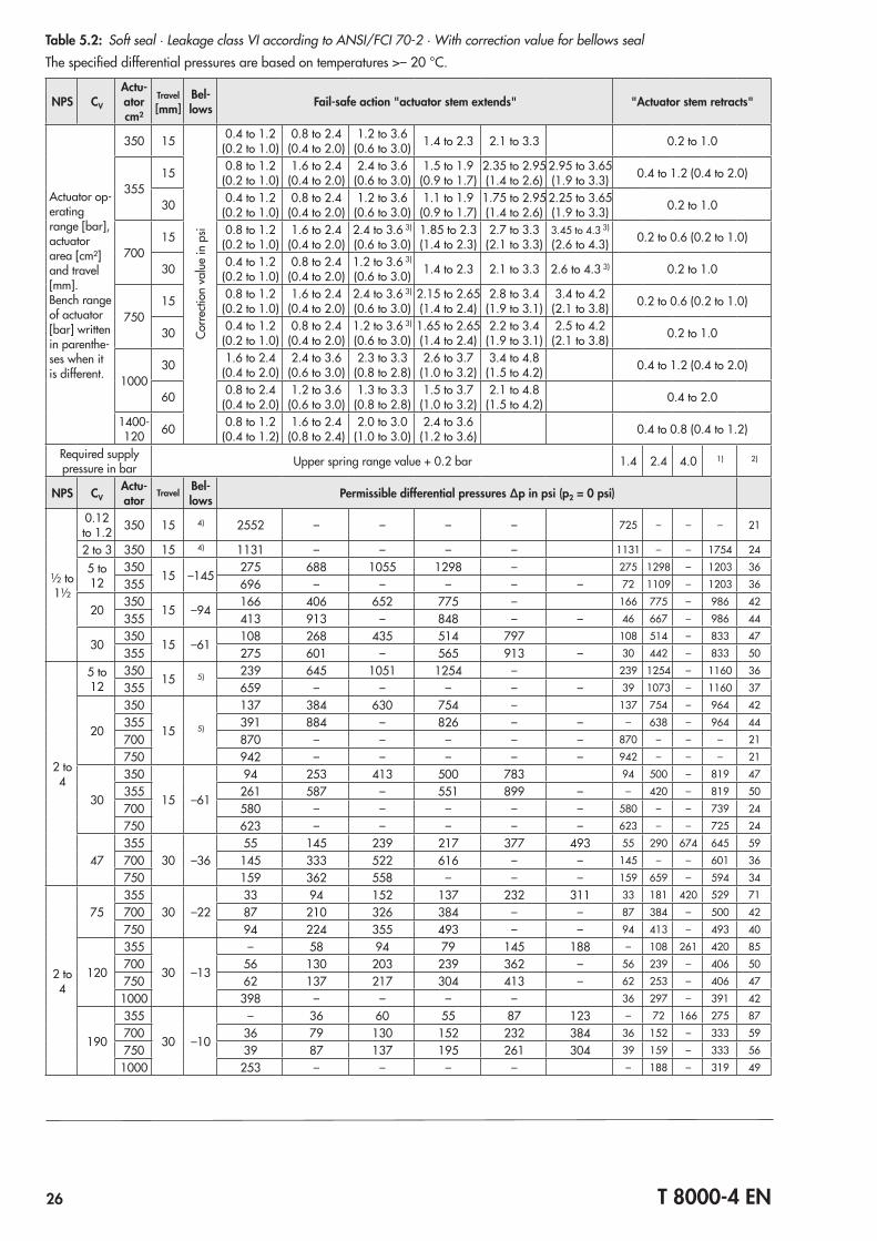
Table 5.2: Soft seal · Leakage class VI according to ANSI/FCI 70‑2 · With correction value for bellows sealThe specified differential pressures are based on temperatures >– 20 °C.
NPS CV
Actu-ator cm²
Travel [mm]
Bel-lows Fail-safe action "actuator stem extends" "Actuator stem retracts"
Actuator op‑erating range [bar], actuator area [cm²] and travel [mm].Bench range of actuator [bar] written in parenthe‑ses when it is different.
350 15
Corre
ction
val
ue in
psi
0.4 to 1.2(0.2 to 1.0)
0.8 to 2.4(0.4 to 2.0)
1.2 to 3.6(0.6 to 3.0) 1.4 to 2.3 2.1 to 3.3 0.2 to 1.0
35515 0.8 to 1.2
(0.2 to 1.0)1.6 to 2.4
(0.4 to 2.0)2.4 to 3.6
(0.6 to 3.0)1.5 to 1.9
(0.9 to 1.7)2.35 to 2.95(1.4 to 2.6)
2.95 to 3.65(1.9 to 3.3) 0.4 to 1.2 (0.4 to 2.0)
30 0.4 to 1.2(0.2 to 1.0)
0.8 to 2.4(0.4 to 2.0)
1.2 to 3.6(0.6 to 3.0)
1.1 to 1.9(0.9 to 1.7)
1.75 to 2.95(1.4 to 2.6)
2.25 to 3.65(1.9 to 3.3) 0.2 to 1.0
70015 0.8 to 1.2
(0.2 to 1.0)1.6 to 2.4
(0.4 to 2.0)2.4 to 3.6 3)
(0.6 to 3.0)1.85 to 2.3(1.4 to 2.3)
2.7 to 3.3(2.1 to 3.3)
3.45 to 4.3 3)
(2.6 to 4.3) 0.2 to 0.6 (0.2 to 1.0)
30 0.4 to 1.2(0.2 to 1.0)
0.8 to 2.4(0.4 to 2.0)
1.2 to 3.6 3)
(0.6 to 3.0) 1.4 to 2.3 2.1 to 3.3 2.6 to 4.3 3) 0.2 to 1.0
75015 0.8 to 1.2
(0.2 to 1.0)1.6 to 2.4
(0.4 to 2.0)2.4 to 3.6 3)
(0.6 to 3.0)2.15 to 2.65(1.4 to 2.4)
2.8 to 3.4(1.9 to 3.1)
3.4 to 4.2(2.1 to 3.8) 0.2 to 0.6 (0.2 to 1.0)
30 0.4 to 1.2(0.2 to 1.0)
0.8 to 2.4(0.4 to 2.0)
1.2 to 3.6 3)
(0.6 to 3.0)1.65 to 2.65(1.4 to 2.4)
2.2 to 3.4(1.9 to 3.1)
2.5 to 4.2(2.1 to 3.8) 0.2 to 1.0
100030 1.6 to 2.4
(0.4 to 2.0)2.4 to 3.6
(0.6 to 3.0)2.3 to 3.3
(0.8 to 2.8)2.6 to 3.7
(1.0 to 3.2)3.4 to 4.8
(1.5 to 4.2) 0.4 to 1.2 (0.4 to 2.0)
60 0.8 to 2.4(0.4 to 2.0)
1.2 to 3.6(0.6 to 3.0)
1.3 to 3.3(0.8 to 2.8)
1.5 to 3.7(1.0 to 3.2)
2.1 to 4.8(1.5 to 4.2) 0.4 to 2.0
1400‑120 60 0.8 to 1.2
(0.4 to 1.2)1.6 to 2.4
(0.8 to 2.4)2.0 to 3.0
(1.0 to 3.0)2.4 to 3.6
(1.2 to 3.6) 0.4 to 0.8 (0.4 to 1.2)
Required supply pressure in bar Upper spring range value + 0.2 bar 1.4 2.4 4.0 1) 2)
NPS CVActu-ator
Travel Bel-lows Permissible differential pressures Δp in psi (p2 = 0 psi)
½ to 1½
0.12 to 1.2 350 15 4) 2552 – – – – 725 – – – 21
2 to 3 350 15 4) 1131 – – – – 1131 – – 1754 24
5 to 12
35015 –145
275 688 1055 1298 – 275 1298 – 1203 36355 696 – – – – – 72 1109 – 1203 36
20350
15 –94166 406 652 775 – 166 775 – 986 42
355 413 913 – 848 – – 46 667 – 986 44
30350
15 –61108 268 435 514 797 108 514 – 833 47
355 275 601 – 565 913 – 30 442 – 833 50
2 to 4
5 to 12
35015 5) 239 645 1051 1254 – 239 1254 – 1160 36
355 659 – – – – – 39 1073 – 1160 37
20
350
15 5)
137 384 630 754 – 137 754 – 964 42355 391 884 – 826 – – – 638 – 964 44700 870 – – – – – 870 – – – 21750 942 – – – – – 942 – – – 21
30
350
15 –61
94 253 413 500 783 94 500 – 819 47355 261 587 – 551 899 – – 420 – 819 50700 580 – – – – – 580 – – 739 24750 623 – – – – – 623 – – 725 24
47355
30 –3655 145 239 217 377 493 55 290 674 645 59
700 145 333 522 616 – – 145 – – 601 36750 159 362 558 – – – 159 659 – 594 34
2 to 4
75355
30 –2233 94 152 137 232 311 33 181 420 529 71
700 87 210 326 384 – – 87 384 – 500 42750 94 224 355 493 – – 94 413 – 493 40
120
355
30 –13
– 58 94 79 145 188 – 108 261 420 85700 56 130 203 239 362 – 56 239 – 406 50750 62 137 217 304 413 – 62 253 – 406 47
1000 398 – – – – 36 297 – 391 42
190
355
30 –10
– 36 60 55 87 123 – 72 166 275 87700 36 79 130 152 232 384 36 152 – 333 59750 39 87 137 195 261 304 39 159 – 333 56
1000 253 – – – – – 188 – 319 49
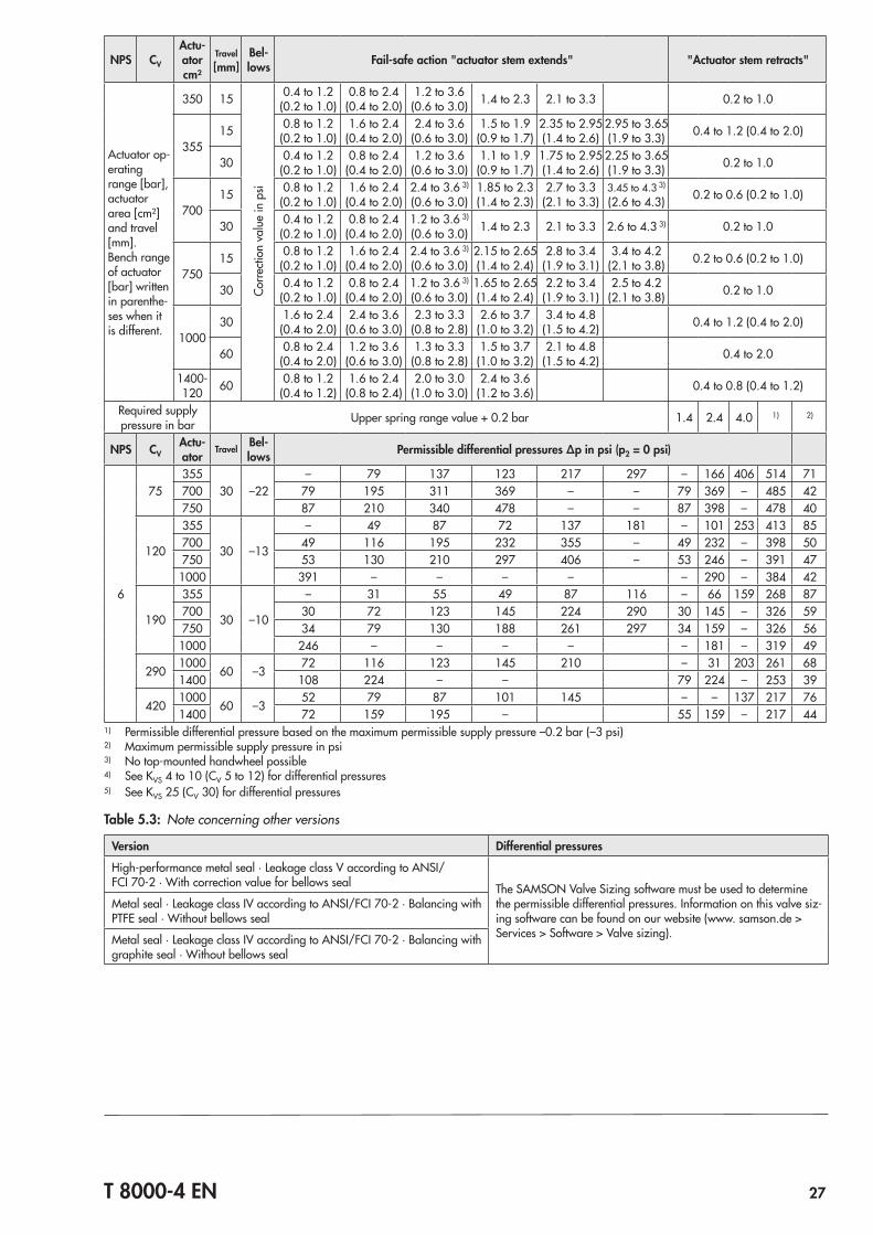
T 8000-4 EN 27
NPS CV
Actu-ator cm²
Travel [mm]
Bel-lows Fail-safe action "actuator stem extends" "Actuator stem retracts"
Actuator op‑erating range [bar], actuator area [cm²] and travel [mm].Bench range of actuator [bar] written in parenthe‑ses when it is different.
350 15
Corre
ction
val
ue in
psi
0.4 to 1.2(0.2 to 1.0)
0.8 to 2.4(0.4 to 2.0)
1.2 to 3.6(0.6 to 3.0) 1.4 to 2.3 2.1 to 3.3 0.2 to 1.0
35515 0.8 to 1.2
(0.2 to 1.0)1.6 to 2.4
(0.4 to 2.0)2.4 to 3.6
(0.6 to 3.0)1.5 to 1.9
(0.9 to 1.7)2.35 to 2.95(1.4 to 2.6)
2.95 to 3.65(1.9 to 3.3) 0.4 to 1.2 (0.4 to 2.0)
30 0.4 to 1.2(0.2 to 1.0)
0.8 to 2.4(0.4 to 2.0)
1.2 to 3.6(0.6 to 3.0)
1.1 to 1.9(0.9 to 1.7)
1.75 to 2.95(1.4 to 2.6)
2.25 to 3.65(1.9 to 3.3) 0.2 to 1.0
70015 0.8 to 1.2
(0.2 to 1.0)1.6 to 2.4
(0.4 to 2.0)2.4 to 3.6 3)
(0.6 to 3.0)1.85 to 2.3(1.4 to 2.3)
2.7 to 3.3(2.1 to 3.3)
3.45 to 4.3 3)
(2.6 to 4.3) 0.2 to 0.6 (0.2 to 1.0)
30 0.4 to 1.2(0.2 to 1.0)
0.8 to 2.4(0.4 to 2.0)
1.2 to 3.6 3)
(0.6 to 3.0) 1.4 to 2.3 2.1 to 3.3 2.6 to 4.3 3) 0.2 to 1.0
75015 0.8 to 1.2
(0.2 to 1.0)1.6 to 2.4
(0.4 to 2.0)2.4 to 3.6 3)
(0.6 to 3.0)2.15 to 2.65(1.4 to 2.4)
2.8 to 3.4(1.9 to 3.1)
3.4 to 4.2(2.1 to 3.8) 0.2 to 0.6 (0.2 to 1.0)
30 0.4 to 1.2(0.2 to 1.0)
0.8 to 2.4(0.4 to 2.0)
1.2 to 3.6 3)
(0.6 to 3.0)1.65 to 2.65(1.4 to 2.4)
2.2 to 3.4(1.9 to 3.1)
2.5 to 4.2(2.1 to 3.8) 0.2 to 1.0
100030 1.6 to 2.4
(0.4 to 2.0)2.4 to 3.6
(0.6 to 3.0)2.3 to 3.3
(0.8 to 2.8)2.6 to 3.7
(1.0 to 3.2)3.4 to 4.8
(1.5 to 4.2) 0.4 to 1.2 (0.4 to 2.0)
60 0.8 to 2.4(0.4 to 2.0)
1.2 to 3.6(0.6 to 3.0)
1.3 to 3.3(0.8 to 2.8)
1.5 to 3.7(1.0 to 3.2)
2.1 to 4.8(1.5 to 4.2) 0.4 to 2.0
1400‑120 60 0.8 to 1.2
(0.4 to 1.2)1.6 to 2.4
(0.8 to 2.4)2.0 to 3.0
(1.0 to 3.0)2.4 to 3.6
(1.2 to 3.6) 0.4 to 0.8 (0.4 to 1.2)
Required supply pressure in bar Upper spring range value + 0.2 bar 1.4 2.4 4.0 1) 2)
NPS CVActu-ator
Travel Bel-lows Permissible differential pressures Δp in psi (p2 = 0 psi)
6
75355
30 –22– 79 137 123 217 297 – 166 406 514 71
700 79 195 311 369 – – 79 369 – 485 42750 87 210 340 478 – – 87 398 – 478 40
120
355
30 –13
– 49 87 72 137 181 – 101 253 413 85700 49 116 195 232 355 – 49 232 – 398 50750 53 130 210 297 406 – 53 246 – 391 471000 391 – – – – – 290 – 384 42
190
355
30 –10
– 31 55 49 87 116 – 66 159 268 87700 30 72 123 145 224 290 30 145 – 326 59750 34 79 130 188 261 297 34 159 – 326 561000 246 – – – – – 181 – 319 49
2901000
60 –372 116 123 145 210 – 31 203 261 68
1400 108 224 – – 79 224 – 253 39
4201000
60 –352 79 87 101 145 – – 137 217 76
1400 72 159 195 – 55 159 – 217 441) Permissible differential pressure based on the maximum permissible supply pressure –0.2 bar (–3 psi)2) Maximum permissible supply pressure in psi3) No top‑mounted handwheel possible4) See KVS 4 to 10 (CV 5 to 12) for differential pressures5) See KVS 25 (CV 30) for differential pressures
Table 5.3: Note concerning other versions
Version Differential pressures
High‑performance metal seal · Leakage class V according to ANSI/FCI 70‑2 · With correction value for bellows seal The SAMSON Valve Sizing software must be used to determine
the permissible differential pressures. Information on this valve siz‑ing software can be found on our website (www. samson.de > Services > Software > Valve sizing).
Metal seal · Leakage class IV according to ANSI/FCI 70‑2 · Balancing with PTFE seal · Without bellows seal
Metal seal · Leakage class IV according to ANSI/FCI 70‑2 · Balancing with graphite seal · Without bellows seal
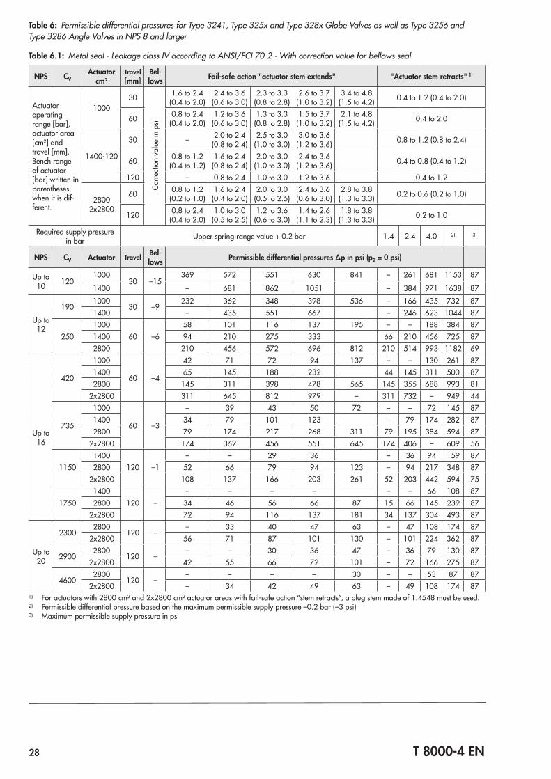
28 T 8000-4 EN
Table 6: Permissible differential pressures for Type 3241, Type 325x and Type 328x Globe Valves as well as Type 3256 and Type 3286 Angle Valves in NPS 8 and larger
Table 6.1: Metal seal · Leakage class IV according to ANSI/FCI 70‑2 · With correction value for bellows seal
NPS CVActuator
cm²Travel [mm]
Bel-lows Fail-safe action "actuator stem extends" "Actuator stem retracts" 1)
Actuator operating range [bar], actuator area [cm²] and travel [mm].Bench range of actuator [bar] written in parentheses when it is dif‑ferent.
100030
Corre
ction
val
ue in
psi
1.6 to 2.4(0.4 to 2.0)
2.4 to 3.6(0.6 to 3.0)
2.3 to 3.3(0.8 to 2.8)
2.6 to 3.7(1.0 to 3.2)
3.4 to 4.8(1.5 to 4.2) 0.4 to 1.2 (0.4 to 2.0)
60 0.8 to 2.4(0.4 to 2.0)
1.2 to 3.6(0.6 to 3.0)
1.3 to 3.3(0.8 to 2.8)
1.5 to 3.7(1.0 to 3.2)
2.1 to 4.8(1.5 to 4.2) 0.4 to 2.0
1400‑120
30 – 2.0 to 2.4(0.8 to 2.4)
2.5 to 3.0(1.0 to 3.0)
3.0 to 3.6(1.2 to 3.6) 0.8 to 1.2 (0.8 to 2.4)
60 0.8 to 1.2(0.4 to 1.2)
1.6 to 2.4(0.8 to 2.4)
2.0 to 3.0(1.0 to 3.0)
2.4 to 3.6(1.2 to 3.6) 0.4 to 0.8 (0.4 to 1.2)
120 – 0.8 to 2.4 1.0 to 3.0 1.2 to 3.6 0.4 to 1.2
28002x2800
60 0.8 to 1.2(0.2 to 1.0)
1.6 to 2.4(0.4 to 2.0)
2.0 to 3.0(0.5 to 2.5)
2.4 to 3.6(0.6 to 3.0)
2.8 to 3.8(1.3 to 3.3) 0.2 to 0.6 (0.2 to 1.0)
120 0.8 to 2.4(0.4 to 2.0)
1.0 to 3.0(0.5 to 2.5)
1.2 to 3.6(0.6 to 3.0)
1.4 to 2.6(1.1 to 2.3)
1.8 to 3.8(1.3 to 3.3) 0.2 to 1.0
Required supply pressure in bar Upper spring range value + 0.2 bar 1.4 2.4 4.0 2) 3)
NPS CV Actuator Travel Bel-lows Permissible differential pressures Δp in psi (p2 = 0 psi)
Up to 10 120
100030 –15
369 572 551 630 841 – 261 681 1153 87
1400 – 681 862 1051 – 384 971 1638 87
Up to 12
1901000
30 –9232 362 348 398 536 – 166 435 732 87
1400 – 435 551 667 – 246 623 1044 87
2501000
60 –658 101 116 137 195 – – 188 384 87
1400 94 210 275 333 66 210 456 725 872800 210 456 572 696 812 210 514 993 1182 69
Up to 16
420
1000
60 –4
42 71 72 94 137 – – 130 261 871400 65 145 188 232 44 145 311 500 872800 145 311 398 478 565 145 355 688 993 81
2x2800 311 645 812 979 – 311 732 – 949 44
735
1000
60 –3
– 39 43 50 72 – – 72 145 871400 34 79 101 123 – 79 174 282 872800 79 174 217 268 311 79 195 384 594 87
2x2800 174 362 456 551 645 174 406 – 609 56
11501400
120 –1– – 29 36 – 36 94 159 87
2800 52 66 79 94 123 – 94 217 348 872x2800 108 137 166 203 261 52 203 442 594 75
17501400
120 –– – – – – – 66 108 87
2800 34 46 56 66 87 15 66 145 239 872x2800 72 94 116 137 181 34 137 304 493 87
Up to 20
23002800
120 –– 33 40 47 63 – 47 108 174 87
2x2800 56 71 87 101 130 – 101 224 362 87
29002800
120 –– – 30 36 47 – 36 79 130 87
2x2800 42 55 66 72 101 – 72 166 275 87
46002800
120 –– – – – 30 – – 53 87 87
2x2800 – 34 42 49 63 – 49 108 174 871) For actuators with 2800 cm² and 2x2800 cm² actuator areas with fail‑safe action “stem retracts”, a plug stem made of 1.4548 must be used.2) Permissible differential pressure based on the maximum permissible supply pressure –0.2 bar (–3 psi)3) Maximum permissible supply pressure in psi
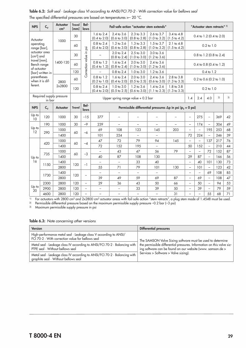
T 8000-4 EN 29
Table 6.2: Soft seal · Leakage class VI according to ANSI/FCI 70‑2 · With correction value for bellows sealThe specified differential pressures are based on temperatures >– 20 °C.
NPS CVActuator
cm²Travel [mm]
Bel-lows Fail-safe action "actuator stem extends" "Actuator stem retracts" 1)
Actuator operating range [bar], actuator area [cm²] and travel [mm].Bench range of actuator [bar] written in parentheses when it is dif‑ferent.
100030
Corre
ction
val
ue in
psi
1.6 to 2.4(0.4 to 2.0)
2.4 to 3.6(0.6 to 3.0)
2.3 to 3.3(0.8 to 2.8)
2.6 to 3.7(1.0 to 3.2)
3.4 to 4.8(1.5 to 4.2) 0.4 to 1.2 (0.4 to 2.0)
60 0.8 to 2.4(0.4 to 2.0)
1.2 to 3.6(0.6 to 3.0)
1.3 to 3.3(0.8 to 2.8)
1.5 to 3.7(1.0 to 3.2)
2.1 to 4.8(1.5 to 4.2) 0.2 to 1.0
1400‑120
30 – 2.0 to 2.4(0.8 to 2.4)
2.5 to 3.0(1.0 to 3.0)
3.0 to 3.6(1.2 to 3.6) 0.8 to 1.2 (0.8 to 2.4)
60 0.8 to 1.2(0.4 to 1.2)
1.6 to 2.4(0.8 to 2.4)
2.0 to 3.0(1.0 to 3.0)
2.4 to 3.6(1.2 to 3.6) 0.4 to 0.8 (0.4 to 1.2)
120 – 0.8 to 2.4 1.0 to 3.0 1.2 to 3.6 0.4 to 1.2
28002x2800
60 0.8 to 1.2(0.2 to 1.0)
1.6 to 2.4(0.4 to 2.0)
2.0 to 3.0(0.5 to 2.5)
2.4 to 3.6(0.6 to 3.0)
2.8 to 3.8(1.3 to 3.3) 0.2 to 0.6 (0.2 to 1.0)
120 0.8 to 2.4(0.4 to 2.0)
1.0 to 3.0(0.5 to 2.5)
1.2 to 3.6(0.6 to 3.0)
1.4 to 2.6(1.1 to 2.3)
1.8 to 3.8(1.3 to 3.3) 0.2 to 1.0
Required supply pressure in bar Upper spring range value + 0.2 bar 1.4 2.4 4.0 2) 3)
NPS CV Actuator Travel Bel-lows Permissible differential pressures Δp in psi (p2 = 0 psi)
Up to 10 120 1000 30 –15 377 – – – – – 275 – 369 42
Up to 12
190 1000 30 –9 239 – – – – – 174 – 304 49
2901000
60 –669 108 123 145 203 – – 195 253 68
1400 101 224 – – 72 224 – 246 39
Up to 16
4201000
60 –447 72 79 94 145 – – 137 217 76
1400 72 152 195 – 50 152 – 210 44
7351000
60 –3– 43 47 56 79 – – 72 152 87
1400 40 87 108 130 29 87 – 166 56
11501400
120 –1– – 33 40 – 40 101 130 73
2800 55 71 79 101 130 – 101 – 123 42
17301400
120 –– – – – – – 69 108 85
2800 39 49 59 69 87 – 69 – 108 47
Up to 20
2300 2800 120 – 29 36 43 50 66 – 50 – 94 532900 2800 120 – – – 33 39 50 – 39 – 79 594600 2800 120 – – – – – 31 – – 55 68 71
1) For actuators with 2800 cm² and 2x2800 cm² actuator areas with fail‑safe action “stem retracts”, a plug stem made of 1.4548 must be used.2) Permissible differential pressure based on the maximum permissible supply pressure –0.2 bar (–3 psi)3) Maximum permissible supply pressure in psi
Table 6.3: Note concerning other versions
Version Differential pressures
High‑performance metal seal · Leakage class V according to ANSI/FCI 70‑2 · With correction value for bellows seal The SAMSON Valve Sizing software must be used to determine
the permissible differential pressures. Information on this valve siz‑ing software can be found on our website (www. samson.de > Services > Software > Valve sizing).
Metal seal · Leakage class IV according to ANSI/FCI 70‑2 · Balancing with PTFE seal · Without bellows seal
Metal seal · Leakage class IV according to ANSI/FCI 70‑2 · Balancing with graphite seal · Without bellows seal
Specifications subject to change without notice
SAMSON AG · MESS- UND REGELTECHNIK Weismüllerstraße 3 · 60314 Frankfurt am Main, Germany Phone: +49 69 4009-0 · Fax: +49 69 4009-1507 [email protected] · www.samson.de T 8000-4 EN 20
17‑0
1‑26
· En
glish