Embed Size (px)
Citation preview
IndustrialHydraulics
Electric Drivesand Controls
Linear Motion andAssembly Technologies Pneumatics
ServiceAutomation
MobileHydraulics
Features– Robust design meeting specifications for mobile applications
– High electromagnetic compatibility (EMC)
– Inputs and outputs with fault detection
– Safety features such as redundant inputs and central safetycut-off for all outputs
– Pulse-width-modulated (PWM) solenoid currents forminimum hysteresis
– Closed-loop control of solenoid currents, i.e. not dependenton voltage and temperature
– Sturdy, sealed aluminum housing
– Watertight with suitable mating connector
Main components
– Powerful 16-bit microcontroller module
– Protected watchdog for program run monitoring
– Serial data interface for diagnostics, parameterization anddisplay of process variables
– CAN bus interface
– Power supply and ground connections for potentiometersand sensors
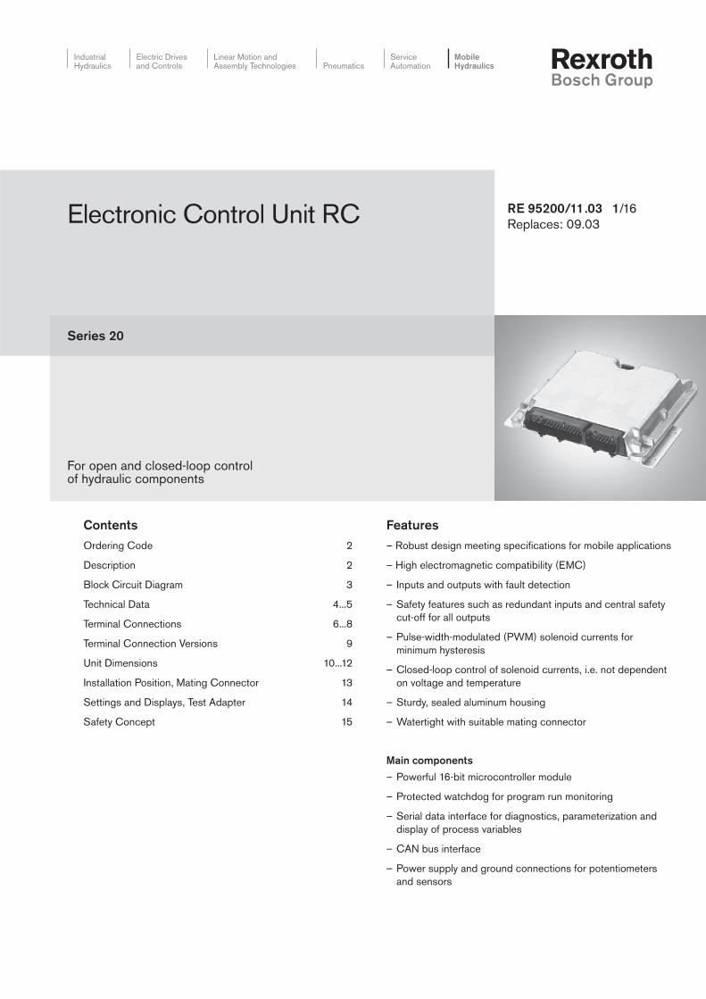
RE 95200/11.03 1/16Replaces: 09.03Electronic Control Unit RC
Series 20
For open and closed-loop controlof hydraulic components
ContentsOrdering Code 2
Description 2
Block Circuit Diagram 3
Technical Data 4...5
Terminal Connections 6...8
Terminal Connection Versions 9
Unit Dimensions 10...12
Installation Position, Mating Connector 13
Settings and Displays, Test Adapter 14
Safety Concept 15
2/16 Bosch Rexroth AG | Mobile Hydraulics RC | RE 95 200/11.03
DescriptionThe RC electronic control units are used for the programmablecontrol of proportional solenoids and additional switchingfunctions. They can therefore be used for both simple andcomplex open and closed-loop control, e.g. for hydrostatictravel drives, work hydraulics or transmission control in mobilemachinery.
RC electronic control units were specially developed for use inmobile machinery, and satisfy the relevant safety requirementswith regard to ambient temperature, tightness, resistance toshock and vibration, as well as electromagnetic compatibility(EMC).
Internally, RC electronic control units comprise a powerful 16-bit microcontroller and all input and output circuitry on a singlecircuit board.
Analog voltages in the range 0...5 V, currents from 0...20 mA,frequencies from 0 Hz...10 kHz and switching information areprocessed as input signals. The inputs are protected againstovervoltage and electrical interference. The voltage inputs canbe monitored to detect any broken wires or short circuits.
The proportional solenoid outputs are pulse-width-modulated(PWM) and optimally adapted for proportional electrical controlof axial piston units and valves to ensure high accuracy andminimum hysteresis.
Ordering Code
Note:
The electronic control units cannot operate without software.Standard software and programs for specific applications are available from Rexroth.
The switch outputs are designed for the direct switching ofrelays, lamps and switch solenoids. The serial interface RS232permits the connection either of the BB-3 control panel(RE 29 798 and RE 95 080) or a laptop with BODEMsoftware for personal computers (RE 95 085) for servicefunctions such as diagnostics, parameterization or display ofprocess variables.
CAN bus interfaces are available with all RC electronic controlunits for exchanging data with other bus users or electronicsystems (e.g. MC or RC electronic control units, joysticks,diesel engine injection, display). The CAN bus interfaces caneach be run with different protocols.
Standard programs are available for the electronic control unitsoftware.If more extensive functions are required, special programpackages for specific applications can also be compiled usinga program library and adapted to the application in questionwith the aid of service tools. Programming with BODAS(RE 95 110) is also possible.
Combined with pumps, motors, valves, sensors, transducersand actuators from Rexroth, RC electronic control units andcorresponding software can be used to create completesystem solutions.
RC / 2 0
Type
Electronic control unit RC
Design
1. digit = no. of proportional outputs 2-2
2. digit = no. of switch outputs 4-4
6-9
Series
2
Index
0
RE 95 200/11.03 | RC Mobile Hydraulics | Bosch Rexroth AG 3/16
+
+-
+-
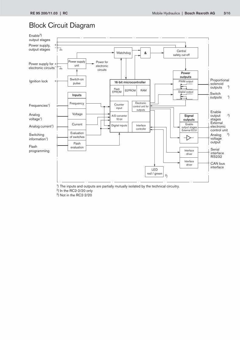
Block Circuit Diagram
1) The inputs and outputs are partially mutually isolated by the technical circuitry.2) In the RC2-2/20 only3) Not in the RC2-2/20
Centralsafety cut-off
Counterinput
PWM output
Enable3)output stages
Frequencies1)
Watchdog
FlashEPROM
Interfacedriver
Switchoutputs
SerialinterfaceRS232
CAN businterface
16-bit microcontroller
Switchinginformation1)
Flashprogramming
Power forelectronic
circuits
Inputs
Frequency
Evaluationof switches
Flashevaluation
LEDred / green
EEPROM RAM
Electroniccontrol unit for
outputs
A/D converter10-bit
Digital inputs Interfacecontroller
&
Poweroutputs
Current
VoltageAnalogvoltage1)
Power supply,output stages
Ignition lock Switch-onpulse
Interfacedriver
Proportionalsolenoidoutputs
Digital output
Power supplyunit
Enableoutput stagesExternal ECU
Signaloutputs
Analogvoltageoutput
Power supply forelectronic circuits
Analog current1)
2)
EnableoutputstagesExternalelectroniccontrol unit
3)
3)
1)
1)
4/16 Bosch Rexroth AG | Mobile Hydraulics RC | RE 95 200/11.03
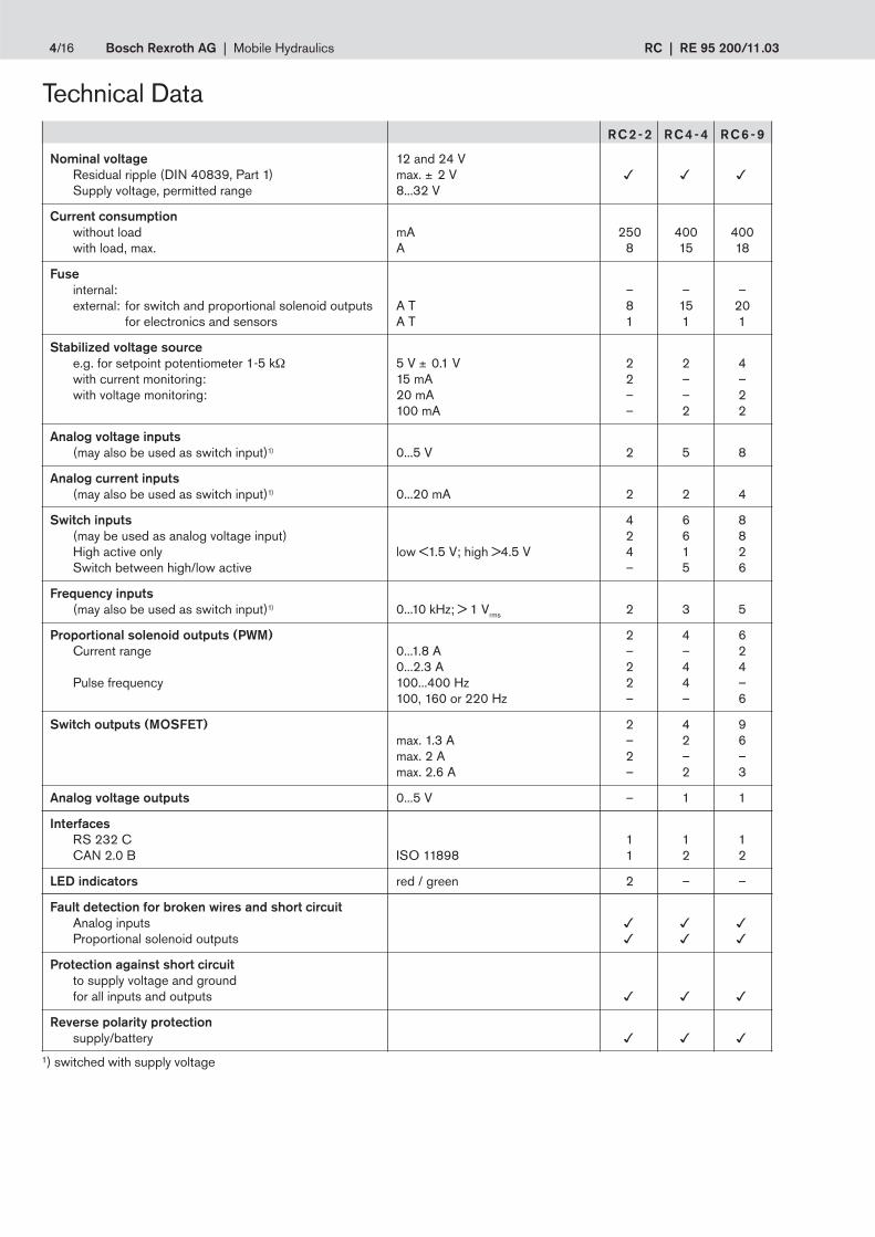
Technical DataRC2-2 RC4-4 RC6-9
Nominal voltage 12 and 24 VResidual ripple (DIN 40839, Part 1) max. ± 2 V
Supply voltage, permitted range 8...32 V
Current consumptionwithout load mA 250 400 400with load, max. A 8 15 18
Fuseinternal: – – –external: for switch and proportional solenoid outputs A T 8 15 20
for electronics and sensors A T 1 1 1
Stabilized voltage sourcee.g. for setpoint potentiometer 1-5 kΩ 5 V ± 0.1 V 2 2 4with current monitoring: 15 mA 2 – –with voltage monitoring: 20 mA – – 2
100 mA – 2 2
Analog voltage inputs(may also be used as switch input)1) 0...5 V 2 5 8
Analog current inputs(may also be used as switch input)1) 0...20 mA 2 2 4
Switch inputs 4 6 8(may be used as analog voltage input) 2 6 8High active only low <1.5 V; high >4.5 V 4 1 2Switch between high/low active – 5 6
Frequency inputs(may also be used as switch input)1) 0...10 kHz; > 1 Vrms 2 3 5
Proportional solenoid outputs (PWM) 2 4 6Current range 0...1.8 A – – 2
0...2.3 A 2 4 4Pulse frequency 100...400 Hz 2 4 –
100, 160 or 220 Hz – – 6
Switch outputs (MOSFET) 2 4 9max. 1.3 A – 2 6max. 2 A 2 – –max. 2.6 A – 2 3
Analog voltage outputs 0...5 V – 1 1
InterfacesRS 232 C 1 1 1CAN 2.0 B ISO 11898 1 2 2
LED indicators red / green 2 – –
Fault detection for broken wires and short circuitAnalog inputs
Proportional solenoid outputs
Protection against short circuitto supply voltage and groundfor all inputs and outputs
Reverse polarity protectionsupply/battery
1) switched with supply voltage
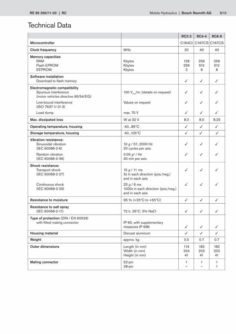
RE 95 200/11.03 | RC Mobile Hydraulics | Bosch Rexroth AG 5/16
RC2-2 RC4-4 RC6-9
Microcontroller C164CI C167CS C167CS
Clock frequency MHz 20 40 40
Memory capacitiesRAM Kbytes 128 256 256Flash EPROM Kbytes 256 512 512EEPROM Kbytes 2 8 8
Software installationDownload to flash memory
Electromagnetic compatibilitySpurious interference 100 Vrms/m; (details on request)
(motor vehicles directive 95/54/EG)
Line-bound interference Values on request
(ISO 7637-1/-2/-3)
Load dump max. 70 V
Max. dissipated loss W at 32 V 8.0 8.0 8.25
Operating temperature, housing -40...85°C
Storage temperature, housing -40...105°C
Vibration resistance:Sinusoidal vibration 10 g / 57...2000 Hz
(IEC 60086-2-6) 20 cycles per axis
Random vibration 0.05 g2 / Hz
(IEC 60086-2-36) 30 min per axis
Shock resistance:Transport shock 15 g / 11 ms
(IEC 60068-2-27) 3x in each direction (pos./neg.)and in each axis
Continuous shock 25 g / 6 ms
(IEC 60068-2-29) 1000x in each direction (pos./neg.)and in each axis
Resistance to moisture 95 % (+25°C to +55°C)
Resistance to salt spray(IEC 60068-2-11) 72 h, 35°C, 5% NaCl
Type of protection (DIN / EN 60529)with fitted mating connector IP 65, with supplementary
measures IP 69K
Housing material Diecast aluminum
Weight approx. kg 0.5 0.7 0.7
Outer dimensions Length (in mm) 114 182 182Width (in mm) 204 202 202Height (in mm) 41 41 41
Mating connector 52-pin 1 1 128-pin – – 1
Technical Data
6/16 Bosch Rexroth AG | Mobile Hydraulics RC | RE 95 200/11.03
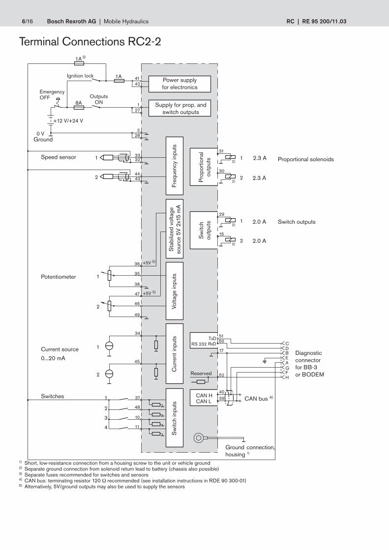
Terminal Connections RC2-2
1) Short, low-resistance connection from a housing screw to the unit or vehicle ground2) Separate ground connection from solenoid return lead to battery (chassis also possible)3) Separate fuses recommended for switches and sensors4) CAN bus: terminating resistor 120 Ω recommended (see installation instructions in RDE 90 300-01)5) Alternatively, 5V/ground outputs may also be used to supply the sensors
8A
1A 3)
27
4241
3332
37
48
10
11
2
1
28
+12 V/+24 V
0 V
30
5150
17
40
52
39
TxDRxD
CAN H
RS 232
CAN L
CDBEAGFH
44
1
1
2
2
1
2
1
2
3
4
1
2
1
2
36
35
38
47
45
46
49
2)
31
34
15
29
1A
+5V 5)
+5V 5)
432)
2)
2)
Supply for prop. andswitch outputs
Power supplyfor electronics
Ground
Switches
Switch outputs
Proportional solenoids
Diagnosticconnectorfor BB-3or BODEM
CAN bus 4)
EmergencyOFF Outputs
ON
Speed sensor
Volta
ge in
puts
Current source
0...20 mA
Potentiometer
Pro
port
iona
lou
tput
sS
witc
hou
tput
s
Ground connection,housing 1)
Ignition lock
Reserved
Freq
uenc
y in
puts
Cur
rent
inpu
tsS
witc
h in
puts
Sta
biliz
ed v
olta
geso
urce
5V
2x1
5 m
A
2.3 A
2.3 A
2.0 A
2.0 A
RE 95 200/11.03 | RC Mobile Hydraulics | Bosch Rexroth AG 7/16
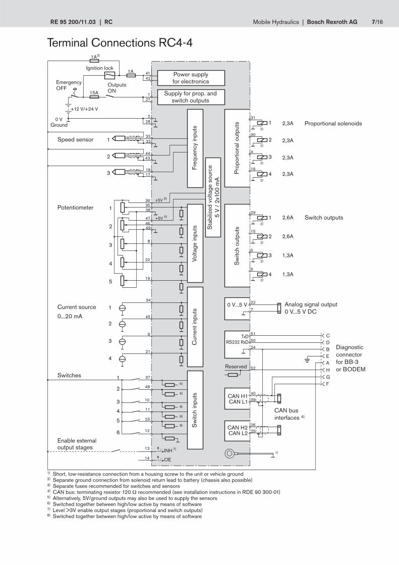
Terminal Connections RC4-4
22
7
51
50
24
40
39
2625
TxDRS232 RxD
0 V...5 V
CAN H1CAN L1
CAN H2CAN L2
CDBEA
1
2
3
6)
15A
1A3)
27
4241
2
1
28
+12 V/+24 V
0 V
1A
37
48
10
11
23
13
14
12
3332
4443
1817
H52
GF
1
2
3
4
2,3A
2,3A
2,3A
2,3A
31
30
4
16
1
2
3
4
2,6A
2,6A
1,3A
1,3A
29
15
5
6
INH
OE
1
2
3
4
5
35 36
38
474649
8
20
19
+5V 5)
+5V 5)
1
245
34
39
421
1
2
3
4
5
6
6)
8)
8)
8)
7)1)
2)
2)
2)
2)
2)
2)
2)
2)
Ground
Switch outputs
Proportional solenoids
Volta
ge in
puts
Freq
uenc
y in
puts
Diagnosticconnectorfor BB-3or BODEM
CAN businterfaces 4)
EmergencyOFF
Ignition lock
Potentiometer
Switches
Analog signal output0 V...5 V DC
Cur
rent
inpu
tsS
witc
h in
puts
Power supplyfor electronics
Supply for prop. andswitch outputs
Sta
biliz
ed v
olta
ge s
ourc
e5
V /
2x1
00 m
A
Current source
0...20 mA
Enable externaloutput stages
Reserved
OutputsON
Speed sensor
1) Short, low-resistance connection from a housing screw to the unit or vehicle ground2) Separate ground connection from solenoid return lead to battery (chassis also possible)3) Separate fuses recommended for switches and sensors4) CAN bus: terminating resistor 120 Ω recommended (see installation instructions in RDE 90 300-01)5) Alternatively, 5V/ground outputs may also be used to supply the sensors6) Switched together between high/low active by means of software7) Level >3V enable output stages (proportional and switch outputs)8) Switched together between high/low active by means of software
Pro
port
iona
l out
puts
Sw
itch
outp
uts
8/16 Bosch Rexroth AG | Mobile Hydraulics RC | RE 95 200/11.03
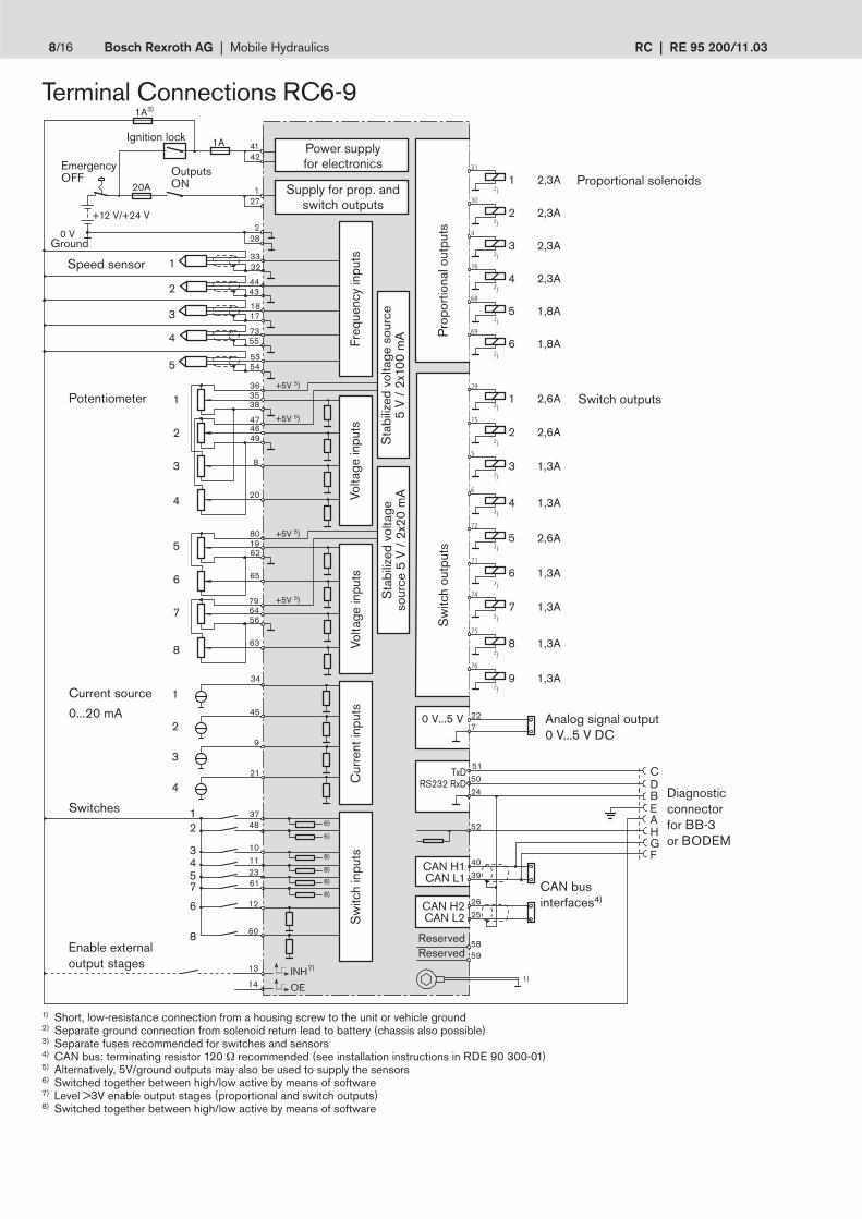
Terminal Connections RC6-9
1) Short, low-resistance connection from a housing screw to the unit or vehicle ground2) Separate ground connection from solenoid return lead to battery (chassis also possible)3) Separate fuses recommended for switches and sensors4) CAN bus: terminating resistor 120 Ω recommended (see installation instructions in RDE 90 300-01)5) Alternatively, 5V/ground outputs may also be used to supply the sensors6) Switched together between high/low active by means of software7) Level >3V enable output stages (proportional and switch outputs)8) Switched together between high/low active by means of software
5
515024
40
39
2625
TxDRS232 RxD
CAN H1CAN L1
CAN H2CAN L2
CDBEA
1
2
228
3748
101123
13
14
61
3332
4443
H52
GF
INH
OE
5859
2)
27
4241
1
1A
20A
1A3)
+12 V/+24 V
0 V
2)
8
31817
47355
55354
5
6
7
801962
65
56
63
6479
1
2
3
363538
46
20
8
49
4
47
12
60
1
2
3
4
2,3A
2,3A
2,3A
2,3A
31
30
4
16
2)
2)
2)
2)
5
6
1,8A
1,8A
68
69
2)
1
2
3
4
2,6A
2,6A
1,3A
1,3A
29
15
5
6
2)
2)
2)
2)
5
6
7
8
2,6A
1,3A
1,3A
1,3A
72
71
74
75
2)
2)
2)
2)
9 1,3A76
227
0 V...5 V
1
245
34
39
421
+5V 5)
+5V 5)
+5V 5)
+5V 5)
7)
6)12
34
7
6)
8)
8)
8)
6
8
8)
1)
Ground
Switch outputs
Proportional solenoids
Volta
ge in
puts
Freq
uenc
y in
puts
Diagnosticconnectorfor BB-3or BODEM
CAN businterfaces4)
EmergencyOFF
Ignition lock
Potentiometer
Switches
Analog signal output0 V...5 V DC
Cur
rent
inpu
tsS
witc
h in
puts
Power supplyfor electronics
Supply for prop. andswitch outputs
Sta
biliz
ed v
olta
ge s
ourc
e5
V /
2x1
00 m
A
Volta
ge in
puts
Sta
biliz
ed v
olta
geso
urce
5 V
/ 2
x20
mA
Current source
0...20 mA
Enable externaloutput stages
ReservedReserved
OutputsON
Pro
port
iona
l out
puts
Sw
itch
outp
uts
Speed sensor
RE 95 200/11.03 | RC Mobile Hydraulics | Bosch Rexroth AG 9/16
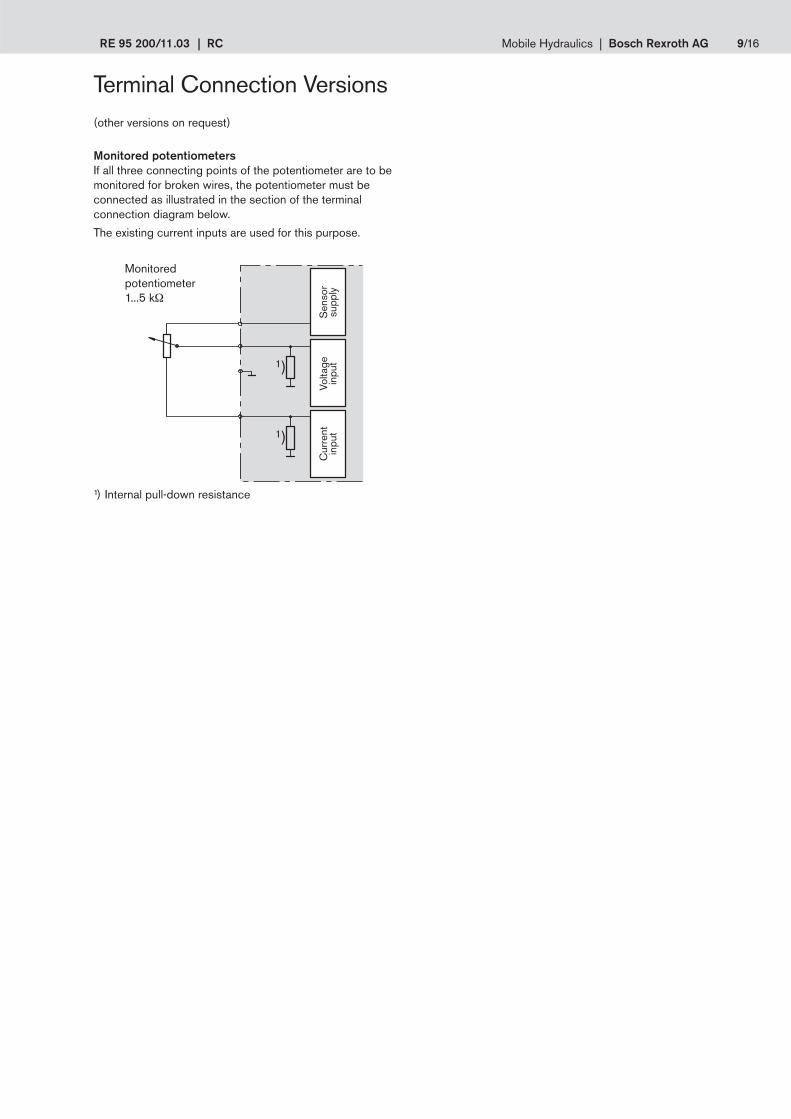
Monitored potentiometersIf all three connecting points of the potentiometer are to bemonitored for broken wires, the potentiometer must beconnected as illustrated in the section of the terminalconnection diagram below.
The existing current inputs are used for this purpose.
1) Internal pull-down resistance
Terminal Connection Versions(other versions on request)
1)
1)
Monitoredpotentiometer1...5 kΩ
Sen
sor
supp
lyVo
ltage
inpu
tC
urre
ntin
put
10/16 Bosch Rexroth AG | Mobile Hydraulics RC | RE 95 200/11.03
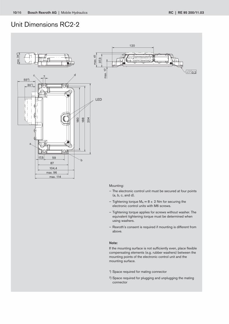
Unit Dimensions RC2-2
Mounting:
– The electronic control unit must be secured at four points(a, b, c, and d).
– Tightening torque MA = 8 ± 2 Nm for securing theelectronic control units with M6 screws.
– Tightening torque applies for screws without washer. Theequivalent tightening torque must be determined whenusing washers.
– Rexroth’s consent is required if mounting is different fromabove.
Note:
If the mounting surface is not sufficiently even, place flexiblecompensating elements (e.g. rubber washers) between themounting points of the electronic control unit and themounting surface.
1) Space required for mating connector
2) Space required for plugging and unplugging the matingconnector
120
7
5917,5
87
104,4max. 96
max. 114
552)
301)
0,2
max
. 41
max
. 341 )
max
. 17
37,3
180
188
204
dc
a
b
LED
RE 95 200/11.03 | RC Mobile Hydraulics | Bosch Rexroth AG 11/16
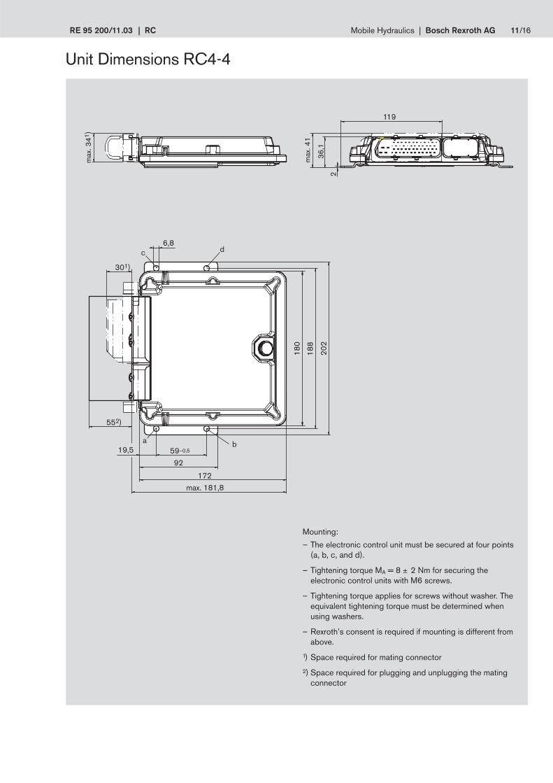
Unit Dimensions RC4-4
119
max
. 41
36,1
2
max
. 341
)
180
6,8
188
202
301)
dc
59–0,5ba
552)
92
19,5
172max. 181,8
Mounting:
– The electronic control unit must be secured at four points(a, b, c, and d).
– Tightening torque MA = 8 ± 2 Nm for securing theelectronic control units with M6 screws.
– Tightening torque applies for screws without washer. Theequivalent tightening torque must be determined whenusing washers.
– Rexroth’s consent is required if mounting is different fromabove.
1) Space required for mating connector
2) Space required for plugging and unplugging the matingconnector
12/16 Bosch Rexroth AG | Mobile Hydraulics RC | RE 95 200/11.03
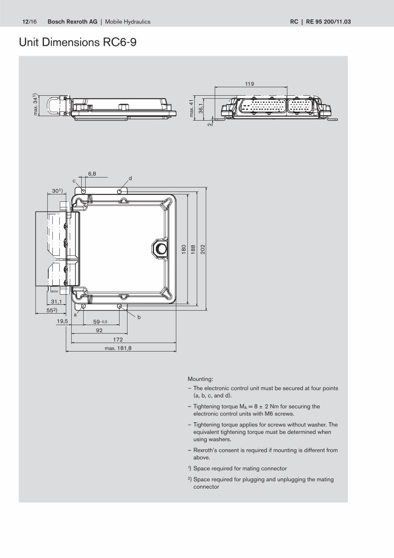
Unit Dimensions RC6-9
19,5
301)
119
max
. 41
36,1
2
max
. 341
)
180
6,8
188
202
dc
31,1
59–0,5ba
552)
92
172max. 181,8
Mounting:
– The electronic control unit must be secured at four points(a, b, c, and d).
– Tightening torque MA = 8 ± 2 Nm for securing theelectronic control units with M6 screws.
– Tightening torque applies for screws without washer. Theequivalent tightening torque must be determined whenusing washers.
– Rexroth’s consent is required if mounting is different fromabove.
1) Space required for mating connector
2) Space required for plugging and unplugging the matingconnector
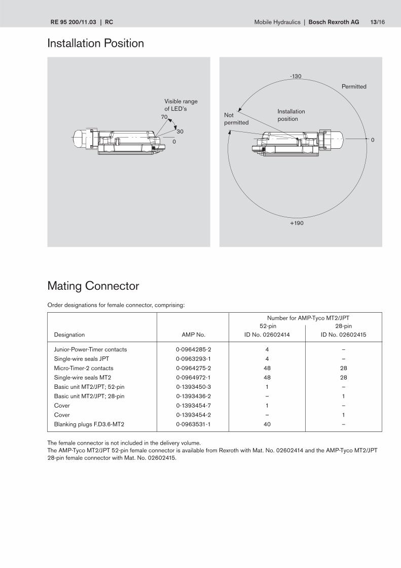
RE 95 200/11.03 | RC Mobile Hydraulics | Bosch Rexroth AG 13/16
Installation Position
70
30
0 0
-130
+190
Visible rangeof LED’s Installation
position
Permitted
Notpermitted
Mating ConnectorOrder designations for female connector, comprising:
Number for AMP-Tyco MT2/JPT 52-pin 28-pin
Designation AMP No. ID No. 02602414 ID No. 02602415
Junior-Power-Timer contacts 0-0964285-2 4 –
Single-wire seals JPT 0-0963293-1 4 –
Micro-Timer-2 contacts 0-0964275-2 48 28
Single-wire seals MT2 0-0964972-1 48 28
Basic unit MT2/JPT; 52-pin 0-1393450-3 1 –
Basic unit MT2/JPT; 28-pin 0-1393436-2 – 1
Cover 0-1393454-7 1 –
Cover 0-1393454-2 – 1
Blanking plugs F.D3.6-MT2 0-0963531-1 40 –
The female connector is not included in the delivery volume.The AMP-Tyco MT2/JPT 52-pin female connector is available from Rexroth with Mat. No. 02602414 and the AMP-Tyco MT2/JPT28-pin female connector with Mat. No. 02602415.

14/16 Bosch Rexroth AG | Mobile Hydraulics RC | RE 95 200/11.03
Test AdapterThe MA test adapter (RE 95090) is used to measure all electrical signals at the inputs, outputs and interfaces of the electroniccontrol unit. It is connected in series between the electronic control unit and the vehicle or unit wiring.
The BB-3 control panel, BODEM software and MA test adapter are all available from Rexroth.
Settings and DisplaysAll settings and the display of functions, faults and system variables are performed using the BB-3 control panel (RE 29798 andRE 95080) or a PC with BODEM software (RE 95085) via the serial interface.

RE 95 200/11.03 | RC Mobile Hydraulics | Bosch Rexroth AG 15/16
Safety ConceptSafety features in the electronic control unit
– The input circuits for speed and analog signals partially feature circuits that are mutually electrically isolated. The switch signalsare electrically separated into mutually independent groups (see block circuit diagram). The microcontroller can detect faults bymeans of duplicate (redundant) input function assignments.
– Broken wires or short circuits at potentiometers can be detected by circuit logic.(See circuit version: Monitored potentiometers)
– Faults in the power supply are detected by internal monitoring.
– All output signals can be monitored by the microcontroller with the appropriate software.
– The power outputs are supplied by separate connections independently of the electronics.For service purposes, the electronic control units can be operated with all power outputs de-energized.
– The internal watchdog module centrally cuts off all proportional and switch outputs in the event of disturbances to the programexecution.
Safety measures during use of the electronic control unit
(See also safety instructions in RDE 90 301-01)
– Faults can be detected and specially programmed safety functions activated by means of duplicated input variable assignments(e.g. connection of the drive pedal signal to two independent analog inputs).
– Special safety functions can be initiated if the plausibility check reveals discrepancies between the setpoints and the values readback by the microcontroller.
Note:
– The suggested circuits do not imply any technical liability of Rexroth for the system.
– The safety instructions contained in RDE 90 301-01 must be observed.
– To switch off the system in emergencies, the power supply to the electronics must be disconnected by an emergency stopswitch. The emergency stop switch must be installed in an easily accessible position for the operator.Safe braking must be ensured when the emergency stop function is activated.
– Cables to speed sensors must be shielded. The shield must be connected to the electronics on one side or to the machine orvehicle ground via a low-resistance connection.
– Cables to the electronics must not be routed close to other power-conducting cables in the machine or vehicle.
– A sufficiently large distance to radio systems must be maintained.
– All connectors must be unplugged from the electronics during electrical welding operations.
– The electronics may only be tested with the proportional solenoids connected.
– The proportional solenoids must not be connected to spark suppression diodes.Switching solenoids at the outputs of the RC electronics need not be connected to spark suppression diodes.Other inductive loads that are in the system but not connected to the RC must be connected to spark suppression diodes.
– In order to preserve the warranty, any installation or replacement of the software (flash EPROM) must be performed bypersonnel from Rexroth.
– Cables/wires must be sealed individually to prevent water from entering the unit.

16/16 Bosch Rexroth AG | Mobile Hydraulics RC | RE 95 200/11.03
Bosch Rexroth AGMobile HydraulicsProduct Unit Mobile ElectronicsElchingen PlantGlockeraustrasse 289275 Elchingen, GermanyTelephone +49 (0) 73 08 82-0Facsimile +49 (0) 73 08 72 [email protected]/mobile-electronics
© 2003 by Bosch Rexroth AG, Mobile Hydraulics, 89275 ElchingenAll rights reserved. Neither this document nor any part of it may be reproduced orstored, processed, duplicated of circulated e. g. by using electronic systems inany form or by any means without the prior authorisation of Bosch Rexroth AG. Incase of infringements the infringing party will be obliged to compensate for alldamages incurred.The data specified in this brochure (data sheet) is intended to describe theproducts. No warranty or statement, whether express or implied with regard tofitness for particular purposes or merchantability may be derived from ourinformation (data sheet). The information provided in this brochure (data sheet)does not release the user from any of its obligations of own judgement andverification for the specific purposes. Please note that our products are subjectto a natural process of wear and tear and aging.


![Hydraulics and Pneumatics [302045]](https://img.pdfslide.us/doc/110x75/61dfe841a282414a66328d09/hydraulics-and-pneumatics-302045.jpg)