Embed Size (px)
Citation preview
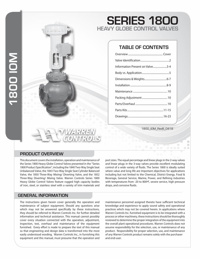
This document covers the installation, operation and maintenance of the Series 1800 Heavy Globe Control Valves presented in the “Series 1800 Product Specification”, including the 1840 Two-Way Single Seat Unbalanced Valve, the 1843 Two-Way Single Seat Cylinder Balanced Valve, the 1850 Three-Way Mixing/ Diverting Valve, and the 1852 Three-Way Diverting/ Mixing Valve. Warren Controls Series 1800 Heavy Globe Control Valves feature rugged high capacity bodies of iron, steel, or stainless steel with a variety of trim materials and
port sizes. The equal percentage and linear plugs in the 2-way valves and linear plugs in the 3-way valves provide excellent modulating control of a wide variety of fluids. The Series 1800 is ideally suited where value and long life are important objectives for applications including but not limited to the Chemical, District Energy, Food & Beverage, General Service, Marine, Power, and Refining industries with temperatures from -20 to 800ºF, severe service, high pressure drops, and corrosive fluids.
The instructions given herein cover generally the operation and maintenance of subject equipment. Should any questions arise which may not be answered specifically by these instructions, they should be referred to Warren Controls Inc. for further detailed information and technical assistance. This manual cannot possibly cover every situation connected with the operation, adjustment, inspection, test, overhaul and maintenance of the equipment furnished. Every effort is made to prepare the text of this manual so that engineering and design data is transformed into the most easily understood wording. Warren Controls Inc., in furnishing this equipment and this manual, must presume that the operation and
maintenance personnel assigned thereto have sufficient technical knowledge and experience to apply sound safety and operational practices which may not be covered herein. In applications where Warren Controls Inc. furnished equipment is to be integrated with a process or other machinery, these instructions should be thoroughly reviewed to determine the proper integration of the equipment into the overall plant operational procedures. Warren Controls does not assume responsibility for the selection, use, or maintenance of any product. Responsibility for proper selection, use, and maintenance of any Warren Controls product remains solely with the purchaserand end-user.
SERIES 18OOHEAVY GLOBE CONTROL VALVES
TABLE OF CONTENTSOverview ..................................................... Cover
Valve Identification ............................................2
Information Present on Valve .....................3-4
Body vs. Application ..........................................5
Dimensions & Weights ..................................6-7
Installation ........................................................8-9
Maintenance ..................................................... 10
Packing Adjustment ....................................... 10
Parts/Overhaul ................................................. 10
Parts Kits .......................................................11-15
Drawings.......................................................16-23
GENERAL INFORMATION
18
00
IOM
1800_IOM_RevB_0418
PRODUCT OVERVIEW

2 2600 Emrick Blvd • Bethlehem, PA 18020 • USA • 800-922-0085 • www.warrencontrols.com 1800_IOM_RevB_0418
0 None
A Type 300,
0-30 PSI
B Type 300,
0-60 PSI
C Type 300,
0-120 PSI
D Type
350SS,
0-100 PSI
Series 1800 Heavy Globe Control Valves are available with a variety of actuators and accessories. These actuators and accessories have separate instructions. For complete control valve installation,
operation, and maintenance instructions see also the instructions for the actuator and accessories in use.
To use these instructions it is necessary to identify the configuration of the valve. Factory assembled control valves have a nameplate mounted on the actuator. The valve’s part number (P/N) is present on the plate. The part number represents the configuration of the control valve. To identify the valve’s type, size, actuator, accessories, and other characteristics decode the part number using configuration
table. If the information is incomplete, incorrect, or not present contact the factory with the valve serial number listed on the plate. (See Information Present on Control Valves section for location of part number, serial number, and other important information on valve.)
Valve Type
Size Body Material
End Connection
TrimStyle
Trim Material
Trim Cv
40 2-Way,
Single
Seat
43 2-Way
Cage
Balanced
50 3-Way
Mixing
52 3-Way
Diverting
050 1/2 inch
075 3/4 inch
100 1 inch
150 1-1/2
inch
200 2 inch
250 2-1/2
inch
300 3 inch
400 4 inch
600 6 inch
800 8 inch
010 10 inch
012 12 inch
F 125/150lb.
Flanged
G 250/300 lb.
Flanged
Model Packing TypeT Teflon
G Graphite
S 316 SS
6 Alloy 6
Wrapped
BonnetConstruction
S 450 Tmax
G Copper Based
Graphalloy Bearings
w/ Ext Bonnet
L Nickel Based
Graphalloy Bearings
w/Ext Bonnet
7 Oxidation Resistant
Graphalloy Bearings
w/Ext Bonnet
Bearings
VALVE BODY
Actuator Series
Action Spring Range
Handwheel Positioners, I/P’s & Limit Switches Air FilterRegulators
SpecialOptions
ASCOSolenoids
0 None
R Reverse
Stem
Fail DownD Direct
Stem
Fail Up
00 None DIAPHRAGMS: 84 DL84 (84 Sq.In.)
8X DL84XR
15 DL115
(115 Sq.In.)
5X DL115XR
CYLINDERS: C2 6” Spring Fail
(for 18H)
C3 8” Spring Fail
(for 18H)
C4 8” Spring Fail
(for 18J)
C5 12” Spring Fail
(for 18J)
0 None or
Cylinder
L Low
3-9psi R/D
F Full
3-15psi R/D
H High
9-15 psi R/D X Xtra-High
DL115XR
0 None
R Reverse
D Direct
0 None
S Special Opts
or Set-up
T SS Tubing
G SS Tagging
B SS Tubing
and Tagging
ACCESSORIES
0 None120 VAC COILS
A 8320G184
3-Way Brass
B 8320G202
3-Way SS
J 8342G1
4-Way Brass
K 8342G701
4-Way SS
L EF8320G184
3-Way EXP Br.
MF8320G202
3-Way EXPSS
V EF8342G1
4-Way EXPBr.
WEF8342G701
4-Way EXPSS 24 Vdc COILS
Z 8320G184
3-Way Brass
0 No Additions L w/Mech. Lmt Swtch’s F w/4-20 Feedback B w/Swtch’s & FeedbackNOTE: L,F,B not available
4th digit spec.
F Full Range Signal, 3-15 PSI or 4-20mA L Low of Split Range, 3-9 PSI or 4-12mA H High of Split Range, 9-15 PSI or 12-20mA
x digit spec.
ACTUATOR
ACTUATORS AND ACCESSORIES
VALVE IDENTIFICATION
FAILURE MODES:
MODE VALVE TYPE
ACTUATOR ACTION
Closed 40/43 ReverseOpen 40/43 DirectUpper Closed* 50/52 DirectUpper Open 50/52 Reverse
*Standard
18H 2” - 4” Bodies
Diaphragm:
84” or 115”
Cylinder: 6” or 8”
18J 6” - 12” Bodies
Diaphragm: 115”
Cylinder: 8” or 12”
18K 1/2” - 1 1/2” Bodies
Diaphragm: 84”
W WCB
F CF8M
R Cast Iron
only avail on
6” - 10” 40,
6” - 12” 43,
8” - 12” 50,
8” - 12” 52
E Equal %
L Linear
Types 50/52
Linear only
F Full Port
1 1st Port Reduction
2 2nd Port
Reduction
3 3rd Port
Reduction
Port reductions only
available to Type 40,
43 & 50. Check factory
for availability of
reductions.
0000 None POSITIONERS:
2xP_ BLX Pneumatic
2xE_ BLX ElectroPneumatic
2xI_ BLX ElectroPneu. Intrn. Safe
2xX_ BLX ElectroPneu. Exp. Proof
2xF_ BLX ElectroPneu. Fail Freeze‡
76P_ Moore760 Pneumatic *
76E_ Moore760 Electro-Pneumatic *TOZO ABB TZIDC 4-20mA. *THN_ ABB TZIDC 4-20mA w/HART Intrn. Safe & Non-Incend *TPN_ ABB TZIDC PROFIBUS PA Intrn. Safe & Non-Incend. TFN_ ABB TZIDC FOUNDATION Fieldbus Intrn. Safe & Non-Incend.THX_ ABB TZIDC 4-20mA w/HART Exp. Proof *TPX_ ABB TZIDC PROFIBUS PA Exp. ProofTFX_ ABB TZIDC FOUNDATION Fieldbus Exp. Proof PROXIMITY SWITCHES:
PX11 Mark 1 Series - 2 ea. SPDT
PX12 Mark 1 Series - 2 ea. SPDT w/2k Pot.
PX13 Mark 1 Series - 2 ea. SPDT w/4-20 Feedback
PX14 Mark 1 Series - 4 ea. SPDT
PX15 Mark 1 Series - 6 ea. SPDT I/P’s Use with Diaphragm Only
MAP1 Type 500X I/P , 3-9 PSI
MAP2 Type 500X I/P, 9-15 PSI
MAP3 Type 500X I/P, 3-15 PSI
MAP4 Type 500X I/P, 1-17 PSI
MAP5 Type 500X I/P, 6-30 PSI
MAP6 Type 550X I/P, 0-30 PSI
MAP7 Type 550X I/P, 0-60 PSI For 15 or 5X only
MAP9 Type 950X I/P, 3-15 EXP

3Series 1800 1800_IOM_RevB_0418
INFORMATION PRESENT ON CONTROL VALVESThere is a great deal of information present on each control valve ranging in importance from the part number and serial number to the color of the paint and casting numbers. This information is important for identifying the valve, installing it correctly, and obtaining parts. Examples of the current factory nameplates and flow arrow plates used on Series 1800 control valves are shown here.
The accompanying table identifies the information present and where to find it on the control valve. There may also be other casting numbers and foundry marks present that do not provide useful information. Customer specific tagging may also present. The plates used, and information present, on Warren Controls other product lines or older valves may be different, contact the factory for details.
ACTUATOR NAMEPLATES
DL84 DL115 & CL
INFORMATION PRESENT ON CONTROL VALVE
PART NUMBER & SERIAL NUMBERInformation Symbol(s) Location NotesPart number(Configuration) P/N On actuator • On Actuator Nameplate attached to leg(s) of actuator.
Serial number S/N On actuatorand valve body
• On Actuator Nameplate attached to leg(s) of actuator. • Sales order number only stamped on top of valve body bonnet.** Number stamped using approximately 1/8 inch tall characters
FLOW DIRECTION(S)Information Symbol(s) Location NotesFlow directionthrough valve On valve body • On Flow Arrow Plate attached to valve body bottom port flange (1800 3-way) between the end connections.
• Arrow cast on valve body between the end connections (1800 2-way).
Port locationsfor 3-way valves
U upper port,L lower port,C common port
On valve body • On Flow Arrow Plate attached to valve body bottom port flange (1800 3-way) between the end connections.
INPUT SIGNAL & SUPPLYInformation Symbol(s) Location NotesInput signal SIG On actuator • On Actuator Nameplate attached to leg(s) of actuator.
Supply pressure SUP or SUPPLY On actuator • On Actuator Nameplate attached to leg(s) of actuator.
VALVE ATTRIBUTES
Information Symbol(s) Location NotesMax temp. rating of valve body
TMAX orTmax
On actuatorand valve body
• On Actuator Nameplate attached to leg(s) of actuator. • On Industrial VBA Nameplate attached to valve body bonnet flange between the end connections on side opposite flow arrow plate.
Trim Cv(Flow coefficient) Cv On valve body • On Industrial VBA Nameplate attached to valve body bonnet flange between the end connections on side op-
posite flow arrow plate.
Trim style(Characteristic) CHAR On valve body • On Industrial VBA Nameplate attached to valve body bonnet flange between the end connections on side op-
posite flow arrow plate.
Trim material TRIM MATL On valve body • On Industrial VBA Nameplate attached to valve body bonnet flange between the end connections on side op-posite flow arrow plate.
Valve bodymaterial On valve body • If the factory applied paint is black the valve body material is iron. If WCB is cast on the valve, and or the factory applied
paint is gray, the valve body material is steel. If CF8M is cast on the valve the valve body material is 316 stainless steel.
FLOW ARROW PLATES
2-WAY FLOW
3-WAY MIXING 3-WAY DIVERTING
3-WAY MIXING AS DIVERTING
3-WAY DIVERTING AS MIXING
VBA NAMEPLATES
INDUSTRIAL VBA

4 2600 Emrick Blvd • Bethlehem, PA 18020 • USA • 800-922-0085 • www.warrencontrols.com 1800_IOM_RevB_0418
1840 2-Way Single Seat Unbalanced Valve The most commonly applied solution with ANSI Class IV shut-off.
Sizes: 6, 8, 10, 12 inch (See 5840 for smaller sizes)Body: ANSI B16.1 Iron 125LB Flange or 250LB Flange (6
thru 10) WCB Steel or CF8M Stainless Steel 150LB Flange or 300LB Flange (6 thru 12)
Trim: EQ% or Linear, 316 Stainless Steel or Alloy 6Packing: TFE V-Ring, Spring Loaded (+32 to 450°F)
Adjustable Graphite (+32 to 500°F) Adjustable Graphite w/Extension Bonnet (+32 to 800°F)
Temperature: +32 to 350°F (125 FLG) +32 to 400°F (250 FLG) +32 to 800°F (150 or 300 FLG)
Rangeability: 50:1
Flow direction is reversed when used with Cylinder Actuator Fail Closed.
1850 3-Way Mixing ValveThis valve has two inlets and one outlet, and is the simplest solution for mixing or bypass applications with ANSI Class IVshut-off. In normal applications the inlet pressures are near equal and control is possible from 5% to 95% of travel with inlet pressures up to 300 PSI. In the 1/2 through 2 inch sizes, the flow can be reversed for diverting if this port configuration is desirable.
Sizes: 1/2, 3/4, 1, 1-1/2, 2, 2-1/2, 3, 4, 6, 8, 10, 12 inchBody: ANSI B16.1 Iron 125LB Flange or 250LB Flange (8
thru 12) WCB Steel or CF8M Stainless Steel 150LB Flange or 300LB Flange (1/2 thru 12)
Trim: Linear, 316 Stainless Steel Packing: TFE V-Ring, Spring Loaded (+32 to 450°F) Adjustable Graphite (+32 to 500°F)
Adjustable Graphite w/Extension Bonnet (+32 to 800°F)
Temperature: +32 to 350°F (125 FLG) +32 to 400°F (250 FLG)
+32 to 800°F (150 or 300 FLG)Rangeability: 30:1 (sizes 1/2 thru 2) 50:1 (sizes 2-1/2 thru 12)
1852 3-Way Diverting/Mixing ValveDesigned as a diverting valve with one inlet and two outlets with ANSI Class II shut-off. However, flow can be reversed for mixing if this port configuration is desirable. The difference between the upper port and lower port pressure must not exceed 50PSID.
Sizes: 2-1/2, 3, 4, 6, 8, 10, 12 inchBody: ANSI B16.1 Iron 125LB Flange or 250LB Flange (8 thru 12)
WCB Steel or CF8M Stainless Steel 150LB Flange or 300LB Flange (2-1/2 thru 12)Trim: Linear, 316 Stainless Steel or Alloy 6Packing: TFE V-Ring, Spring Loaded (+32 to 450°F)
Adjustable Graphite (+32 to 500°F)O-Ring: Fluoraz 797 (2-1/2 thru 4)
EPR (6 thru 12)Temperature: +32 to 150°F (125 or 250 FLG, 8 thru 12)
+32 to 500°F (150 or 300 FLG, 2-1/2 thru 4) +32 to 150°F (150 or 300 FLG, 6 thru 12)
Rangeability: 50:1
2-WAY VALVES (Control of Liquids, Gases, and Steam)
3-WAY VALVES (Control of Liquids)
Stem Down
The upper port opensand the lower port closes
Upper Port Lower Port
Common Port
Flow Flow
Stem Up
The upper port closesand the lower port opens
Upper Port Lower Port
Common PortFlow
Stem Down
The valve closes
Stem Up
The valve opens
Stem Down
The upper port opensand the lower port closes
Upper Port Common Port
Lower PortFlow
Flow Flow
Stem Up
The upper port closesand the lower port opens
Upper Port Common Port
Lower PortFlow
Flow Flow
Stem Down
The valve closes
Stem Up
The valve opens
Flow Flow
Stem Down
The valve closes
Stem Up
The valve opens
Stem Down
The upper port opensand the lower port closes
Upper Port Lower Port
Common Port
Flow Flow
Stem Up
The upper port closesand the lower port opens
Upper Port Lower Port
Common PortFlow
Stem Down
The valve closes
Stem Up
The valve opens
Stem Down
The upper port opensand the lower port closes
Upper Port Common Port
Lower PortFlow
Flow Flow
Stem Up
The upper port closesand the lower port opens
Upper Port Common Port
Lower PortFlow
Flow Flow
Stem Down
The valve closes
Stem Up
The valve opens
Flow Flow
Stem Down
The valve closes
Stem Up
The valve opens
1843 2-Way Single Seat Cylinder Balanced ValveA balanced valve that is an effective solution for higher pressures. It requires less force to operate than unbalanced valves so smaller actuators can be used. Its single seat o-ring seal design facilitates ANSI Class IV shut-off. It is limited to cleaner fluids.
Sizes: 6, 8, 10, 12 inch (See 5843 for smaller sizes)Body: ANSI B16.1 Iron 125LB Flange or 250LB Flange WCB Steel or CF8M Stainless Steel 150LB Flange or
300LB Flange Trim: EQ% or Linear, 316 Stainless Steel or Alloy 6Packing: TFE V-Ring, Spring Loaded (+32 to 450°F) Adjustable Graphite (+32 to 500°F)O-Ring: Fluoraz 797Temperature: +32 to 350°F (125 FLG)
+32 to 400°F (250 FLG) +32 to 500°F (150 or 300 FLG)
Rangeability: 50:1
Flow direction is reversed when used with Cylinder Actuator Fail Closed.
INFORMATION PRESENT ON MONITROL CONTROL VALVES BODY STYLE VERSUS APPLICATION

5Series 1800 1800_IOM_RevB_0418
NOTE: -20ºF T MIN temperature limit is for indoor applications with low humidity where ice will not form on the stem.
FLUID TEMPERATURE LIMITS
Valve Type
BodyMaterial & Code
EndConnection&& Code
PackingTypeCode
BonnetConstruction & Code
T MAX T MIN
40 2-Way Single Seat
WCB W, CF8M F 150 lb F, 300 lb G Teflon T Standard S 450ºF 60ºFWCB W, CF8M F 150 lb F, 300 lb G Graphite G Standard S 500ºF -20ºFWCB W, CF8M F 150 lb F, 300 lb G Graphite G Ext. Bonnet X 800ºF -20ºFCast Iron R 125 lb F Teflon T Standard S 350ºF 60ºFCast Iron R 125 lb F Graphite G Standard S 350ºF -20ºFCast Iron R 250 lb G Teflon T Standard S 400ºF 60ºFCast Iron R 250 lb G Graphite G Standard S 400ºF -20ºF
43 2-Way Cage-Balanced w/Fluoraz 797 O-Ring
WCB W, CF8M F 150 lb F, 300 lb G Teflon T Standard S 450ºF 60ºFWCB W, CF8M F 150 lb F, 300 lb G Graphite G Standard S 450ºF 23ºFCast Iron R 125 lb F Teflon T Standard S 350ºF 60ºFCast Iron R 125 lb F Graphite G Standard S 350ºF 23ºFCast Iron R 250 lb G Teflon T Standard S 400ºF 60ºFCast Iron R 250 lb G Graphite G Standard S 400ºF 23ºF
50 3-Way Mixing
WCB W, CF8M F 150 lb F, 300 lb G Teflon T Standard S 450ºF 60ºFWCB W, CF8M F 150 lb F, 300 lb G Graphite G Standard S 500ºF -20ºFWCB W, CF8M F 150 lb F, 300 lb G Graphite G Ext. Bonnet X 800ºF -20ºFCast Iron R 125 lb F Teflon T Standard S 350ºF 60ºFCast Iron R 125 lb F Graphite G Standard S 350ºF -20ºFCast Iron R 250 lb G Teflon T Standard S 400ºF 60ºFCast Iron R 250 lb G Graphite G Standard S 400ºF -20ºF
52 3-Way Divet. (2-1/2” - 4”) w/Flz. 797 O-Ring Seal
WCB W, CF8M F 150 lb F, 300 lb G Teflon T Standard S 450ºF 60ºF
WCB W, CF8M F 150 lb F, 300 lb G Graphite G Standard S 450ºF 23ºF
52 3-Way Divet. (6” - 12”) w/EPR OCT O-Ring
WCB W, CF8M F 150 lb F, 300 lb G Teflon T Standard S 150ºF 60ºFWCB W, CF8M F 150 lb F, 300 lb G Graphite G Standard S 150ºF -20ºFCast Iron R 125 lb F, 250 lb G Teflon T Standard S 150ºF 60ºFCast Iron R 125 lb F, 250 lb G Graphite G Standard S 150ºF -20ºF
PERFORMANCE/LIMITS
Pressure ratings are PSIG For applications below 32º consult factory
BODY PRESSURE-TEMPERATURE RATINGS:
Temp. (F)
125 FLGIron
250 FLGIron
150 FLGSteel
300 FLGSteel
150 FLGSt Steel
300 FLGSt Steel
+32° To 100° 175 400 285 740 275 720150° 175 400 272 710 255 670175° 170 385 266 695 245 645200° 165 370 260 680 235 620225° 155 355 252 673 230 605250° 150 340 245 667 225 590275° 145 325 237 661 220 575300° 140 310 230 655 215 560325° 130 295 222 650 210 548350° 125 280 215 645 205 537375° - 265 207 640 200 526400° - 250 200 635 195 515450° - - 185 620 182 497500° - - 170 605 170 480550° - - 155 587 155 465600° - - 140 570 140 450650° - - 125 550 125 440700° - - 110 530 110 435750° - - 95 505 95 425800° - - 80 410 80 420
TRIM MATERIALS
FLOWINGDIFFERENTIALPRESSURE LIMIT
316 Stainless Steel 100 PSIDAlloy 6 300 PSID

6 2600 Emrick Blvd • Bethlehem, PA 18020 • USA • 800-922-0085 • www.warrencontrols.com 1800_IOM_RevB_0418
DIMENSIONS & WEIGHTS
2-WAY 3-WAY
Valves shown with DL84 Actuator as typical.
For additional actuator information see Series 1800 Product Specification and the Installation Operation and Maintenance Instructions for the actuator in use.

7Series 1800 1800_IOM_RevB_0418
DIMENSIONS & WEIGHTS
Face to face dimensions conform to ANSI/ISA S75.03
CF = Consult factory
Actual Shipping Weights May Vary
Face to face dimensions conform to ANSI/ISA S75.03
CF = Consult factory
Actual Shipping Weights May Vary
DIMENSION (IN) 1840 VALVE SIZE (IN)
6 8 10 12
A 125 or 150FLG 17-3/4 21-3/8 26-1/2 29 250 or 300FLG 18-5/8 22-3/8 27-7/8 30-1/2
B 11-7/8 13-3/4 15-1/4 15-1/4
C Standard 13-7/8 15-1/4 16-1/8 17Extension Bonnet 17-5/8 CF CF CF
Weight (LB) Standard 390 650 1160 CFExtension Bonnet 400 CF CF CF
DIMENSION (IN) 1843 VALVE SIZE (IN)
6 8 10 12
A 125 or 150FLG 17-3/4 21-3/8 26-1/2 29250 or 300FLG 18-5/8 22-3/8 27-7/8 30-1/2
B 11-7/8 13-3/4 15-1/4 15-1/4C 14-1/2 15-7/8 16-3/4 17-3/4Weight (LB) 455 760 1360 CF
DIMENSION (IN) 1850 VALVE SIZE (IN)
1/2 3/4 1 1-1/2 2 2-1/2 3 4 6 8 10 12
A 125 or 150FLG 7-1/4 7-1/4 7-1/4 8-3/4 10 10-7/8 11-3/4 13-7/8 17-3/4 21-3/8 26-1/2 29250 or 300FLG 7-1/2 7-5/8 7-3/4 9-1/4 10-1/2 11-1/2 12-1/2 14-1/2 18-5/8 22-3/8 27-7/8 30-1/2
B 125 or 150FLG 6-1/2 6-1/2 6-1/2 6-1/4 10 10-1/4 11-1/4 13-7/8 15-7/8 17-3/4 21-1/8 20-3/8250 or 300FLG 6-5/8 6-3/4 6-3/4 6-1/2 10-1/4 10-5/8 11-5/8 14-1/8 16-1/4 18-1/4 21-3/4 21-1/8
C Standard 5-1/2 5-1/2 5-1/2 6-1/8 8-1/8 8-7/8 9-5/8 10-3/8 13-7/8 15-1/4 16-1/8 17Extension Bonnet CF CF CF CF CF CF 14-5/8 CF 17-5/8 CF CF CF
Weight (LB) Standard CF CF CF CF CF 140 210 390 545 900 1600 CFExtension Bonnet CF CF CF CF CF CF 215 CF 555 CF CF CF
DIMENSION (IN) 1852 VALVE SIZE (IN)
2-1/2 3 4 6 8 10 12
A 125 or 150FLG 10-7/8 11-3/4 13-7/8 17-3/4 21-3/8 26-1/2 29250 or 300FLG 11-1/2 12-1/2 14-1/2 18-5/8 22-3/8 27-7/8 30-1/2
B 125 or 150FLG 10-1/4 11-1/4 13-7/8 15-7/8 17-3/4 21-1/8 20-3/8250 or 300FLG 10-5/8 11-5/8 14-1/8 16-1/4 18-1/4 21-3/4 21-1/8
C 9-1/2 10-1/4 11 14-1/2 15-7/8 16-3/4 17-3/4Weight (LB) 140 210 390 545 900 1600 CF
1840 2-way
1843 2-way
1850 3-way
1852 3-way

8 2600 Emrick Blvd • Bethlehem, PA 18020 • USA • 800-922-0085 • www.warrencontrols.com 1800_IOM_RevB_0418
See also separate actuator and accessory instructions for additional installation guidelines.
• Be sure that the flow medium, ambient temperature and the selected location will not exceed the maximum temperature of the valve, actuator, or accessories. Infor-mation can be found in the product specifications and on the nameplate(s) regard-ing these limits (See Information Present on Control Valves section for location of important information on valve).
• Follow good piping practices. Install a bypass around the valve. Install stop valves in inlet and outlet piping to provide means to isolate valve.
• A straight run of pipe is recommended for 10 pipe diameters upstream of the valve and 20 pipe diameters downstream of the valve.
• Protect valve and downstream equipment with a self-cleaning strainer.
• Provide proper inlet and outlet drainage in steam service to prevent water hammer or possible erosion in equipment.
• Install gauges in inlet and outlet piping to provide means for checking adjustment and operation.
• For maximum efficiency and minimum wear install valve in vertical position with the stem pointing upward.
VERTICAL ABOVE PIPING IS CORRECT MOUNTING POSITION.All other positions reduce service life of equipment.
NEXT BEST POSITION45º from vertical above piping on either side. Valve must have an 8 Bolt Flange.
WORST POSITION (Horizontal on either side).
VERTICAL BELOW PIPING
Position is suitable for gases, but NOT for liquids or steam.
A non-vertical mounting position may be necessary to protect actuator in high temperature applications, but may reduce packing life.
OPTION B: L’s with U-BOLTS
Actuators mounted in any position other than vertical MUST be supported independent of the valve.
OPTION A: Hanger Cable
!INSTALLATION
Check valve for any damage due to improper storage or transpertation. Immediately notify your sales organization of any damaged goods upon receipt. Do not attempt to move or distrub the valve further so photos may be taken. If the shipping container is noticeably damaged refuse receipt, as the shipping company should be held liable until a shipping represenative is available to take photos.

9Series 1800 1800_IOM_RevB_0418
• Close inlet and outlet stop
valves.
• Check that valve responds through rated travel in relation to changes in input signal. Rated travel is shown by position of travel indicator on valve stem relative to travel indicator on yoke.
• For valves fitted with a handwheel, manually operate valve with no air applied, using handwheel through rated travel to check freedom of movement. Return handwheeel to its standby position.
• Place valve in operation.
• Actuators mounted in any position other than vertical must be supported in-dependent of the valve.
• Be sure to leave clearance to allow for actuator removal (See Dimensions & Weights section for actuator removal clearance).
• Before installing, be sure valve and piping are clean inside and free of scale, chips, welding spatter, and foreign material. Thoroughly blow out or flush pipe lines.
• The valve must be installed with the fluid flowing in the correct direction(s). For proper operation in all applications, control valves must be piped accord-ing to the corresponding flow arrows, inlet markings, and port markings pres-ent on each valve (See Information Present on Control Valves section for location of important information on valve).
• Pipes must be aligned squarely with the valve at each connection.
• If the valve has screwed ends, do not apply pipe dope to the threads of the valve body or to the first two threads of the pipe.
• If the valve has flanged ends, tighten flange bolts evenly to prevent excessive stress and the possibility of cracking.
• If the valve has welded ends, prevent plug and cage distortion by keeping excess heat from the body.
• The valve, actuator, and accessories (if so equipped) are assembled, tested, and calibrated at the factory. The actuator nameplate specifies set-up parameters used (See Information Present on Control Valves section for location of important information on valve). Do not exceed the supply pressure listed on the actuator nameplate or you will damage the valve and void the warranty.
• Supply air, instrument signal, and accessories should be connected to ports or terminals as indicated on the control valve.
• Final tuning may be required under actual operating conditions.
• On critical or dangerous equipment, provide suitable safety and emergency systems to protect personnel and property from injury due to a valve malfunction. If the valve handles flammable, toxic, corrosive or explosive fluids, provide for safety in the event of valve leakage or malfunction.
• Do not obscure flow arrow plates or nameplates with paint. If flow arrow plates or nameplates will be covered with insulation, it is recommended the information on the plates be transcribed on the outside of the insulation in the same location as the plate.
OPERATION
For proper operationin all applications,
control valves mustbe piped properly.
If you need detailedinformation, please
refer to the "HeatExchanger Bypass
Piping Applications"document.
INSTALLATION
10 2600 Emrick Blvd • Bethlehem, PA 18020 • USA • 800-922-0085 • www.warrencontrols.com 1800_IOM_RevB_0418
MAINTENANCE
PACKING ADJUSTMENT
PARTS/OVERHAUL
Series 1800 Heavy Globe Control Valves have adjustable packing. If a packing leak is observed, tighten the hex nuts above the packing flange ¼ turn and observe. If the leak continues tighten the hex nuts
another ¼ turn and observe. Repeat as necessary. If the leak continues and the hex nuts cannot be tightened further with reasonable force replace the packing and if necessary the stem and plug assembly.
Damaged or worn parts can decrease performance and shorten valve life.
Damaged or worn packing parts including the packing, bearings, spring, and other bonnet parts can cause a packing leak resulting in damage to the actuator, accessories, and surrounding equipment. Damaged or worn packing parts can also cause increased hysteresis resulting in poor control.
Damaged or worn trim parts including the plug, stem, seat ring, piston, piston guide, piston seal, and o-ring can cause increased hysteresis, poor control, excessive internal leakage, and poor shut-off. Damaged or worn trim parts can also cause damage to the packing parts resulting in a packing leak.
Damaged or worn body gaskets or o-ring seals can cause external leakage resulting in damage to the actuator, accessories, and surrounding equipment.
Should parts become worn or damaged, parts kits are available. Repack Kits are available to replace the packing. Repack/Inspection Kits are available to allow the valve to be opened for inspection of its internal parts. Rebuild/Repack Kits are available to completely rebuild/ overhaul the valve. Parts kits come with complete step-by-step instructions. Each kit has its own part number. Please provide the valve’s serial number to ensure getting the correct kit part number and correct parts.
Series 1800 Heavy Globe Control Valves are for the most part maintenance free when properly selected and installed. Rebuilding of these valves should not be necessary under normal operating conditions. For best operation follow installation guidelines (See Installation section); maintain the fluid pressure, temperature, flow, flowing differential pressure, and shut-off differential pressure within the limits of the valve (See Series 1800 Product Specification for details). In installations where high vibration exists, pneumatic and/or electrical connections should periodically be checked for integrity. In water or water and glycol applications, good water quality must be maintained or the service life of the valve may be reduced (See Water Quality Guidelines). The valve stem must be kept free of debris, deposits, dirt, dust, and scratches or the packing parts may be damaged resulting in a packing leak. Control valve hunting will
cause excessive stroking of the valve stem and result in premature failure of the packing seal. The system must be stabilized to prevent hunting to ensure reasonable packing life and optimal control performance. Oversizing of a control valve will result in an unstable condition, which can cause noise, vibration, and premature trim and packing seal failure. The use of Warren Controls ValveWorks sizing program will facilitate the selection of the optimum valve.
!CAUTION
DO NOT attempt to service a Series 1800 valve without having a Repack/Inspection Kit & Supplemental instructions on hand.

11Series 1800 1800_IOM_RevB_0418
PARTS KITS
REPACK KITFOR PACKING TYPE & BONNET CONSTRUCTION TS TEFLON 450 TMAXSIZE 050 thru 150 (1/2 thru 1-1/2 inch)SEE DWG C3762003
ITEM QTY DESCRIPTION ITEM QTY DESCRIPTION2 2 HEX NUT 8 1 SPRING3 1 PACKING FLANGE 9 1 SLEVE BEARING 1/4 LG4 1 PACKING FOLLOWER 10 1 STEM WIPER5 1 SLEVE BEARING 1/2 LG 11 1 PACKING BOX RING6 1 V-RING PACKING SET 12 1 WIPER RETAINER7 1 PACKING LOAD WASHER 14 1 TUBE STEM LUBE
REPACK KITFOR PACKING TYPE & BONNET CONSTRUCTION TS TEFLON 450 TMAXSIZE 200 thru 400 (2 thru 4 inch)SEE DWG C3761307
ITEM QTY DESCRIPTION ITEM QTY DESCRIPTION2 2 HEX NUT 8 1 SPRING3 1 PACKING FLANGE 9 1 SLEVE BEARING 3/8 LG4 1 PACKING FOLLOWER 10 1 PACKING BOX RING5 1 SLEVE BEARING 3/4 LG 11 1 STEM WIPER6 1 V-RING PACKING SET 12 1 WIPER RETAINER7 1 PACKING LOAD WASHER 14 1 TUBE STEM LUBE
REPACK KITFOR PACKING TYPE & BONNET CONSTRUCTION TS TEFLON 450 TMAXSIZE 600 thru 012 (6 thru 12 inch)SEE DWG C3762003
ITEM QTY DESCRIPTION ITEM QTY DESCRIPTION2 2 HEX NUT 8 1 SPRING3 1 O-RING 9 1 PACKING BOX RING4 1 PACKING FLANGE 10 1 STEM WIPER5 1 SPACKING FOLLOWER 11 1 PWIPER RETAINER6 1 V-RING PACKING SET 13 1 TUBE STEM LUBE7 1 PACKING LOAD WASHER
12 2600 Emrick Blvd • Bethlehem, PA 18020 • USA • 800-922-0085 • www.warrencontrols.com 1800_IOM_RevB_0418
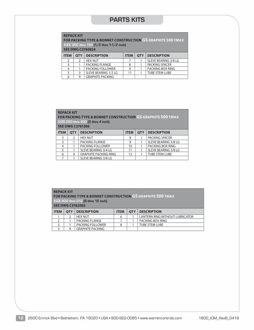
REPACK KITFOR PACKING TYPE & BONNET CONSTRUCTION GS GRAPHITE 500 TMAXSIZE 050 thru 150 (1/2 thru 1-1/2 inch)SEE DWG C3760824
ITEM QTY DESCRIPTION ITEM QTY DESCRIPTION2 2 HEX NUT 7 1 SLEVE BEARING 3/8 LG3 1 PACKING FLANGE 8 1 PACKING SPACER4 1 PACKING FOLLOWER 9 1 PACKING BOX RING5 3 SLEVE BEARING 1/2 LG 11 1 TUBE STEM LUBE6 9 GRAPHITE PACKING
REPACK KITFOR PACKING TYPE & BONNET CONSTRUCTION GS GRAPHITE 500 TMAXSIZE 200 thru 400 (2 thru 4 inch)SEE DWG C3761306
ITEM QTY DESCRIPTION ITEM QTY DESCRIPTION2 2 HEX NUT 8 1 PACKING SPACER3 1 PACKING FLANGE 9 1 SLEVE BEARING 3/8 LG4 1 PACKING FOLLOWER 10 1 PACKING BOX RING5 1 SLEVE BEARING 3/4 LG 11 1 SLEVE BEARING 5/8 LG6 9 GRAPHITE PACKING RING 13 1 TUBE STEM LUBE7 1 SLEVE BEARING 3/8 LG
REPACK KITFOR PACKING TYPE & BONNET CONSTRUCTION GS GRAPHITE 500 TMAXSIZE 600 thru 012 (6 thru 12 inch)SEE DWG C3762002
ITEM QTY DESCRIPTION ITEM QTY DESCRIPTION1 2 HEX NUT 6 1 LANTERN RING WITHOUT LUBRICATOR2 1 PACKING FLANGE 7 1 PACKING BOX RING3 1 PACKING FOLLOWER 8 1 TUBE STEM LUBE5 9 GRAPHITE PACKING
PARTS KITS

13Series 1800 1800_IOM_RevB_0418
REBUILD/REPACK KITFOR MODEL 18J VALVE TYPE 40SEE DWG D3241932
ITEM QTY DESCRIPTION ITEM QTY DESCRIPTION
1 1 VALVE STEM 11 2 GASKET
6 1 GROOVE PIN 13 1 TUBE THREAD SEALANT
7 1 PLUG 1 TUBE ANTI-SEIZE LUBE
9 1 SEAT RING 1 REPACK KIT
REPACK/INSPECTION KITFOR MODEL 18J VALVE TYPE 40SEE DWG D3241932
ITEM QTY DESCRIPTION
11 2 GASKET
1 TUBE ANTI-SEIZE LUBE
1 REPACK KIT
REPACK/INSPECTION KITFOR MODEL 18J VALVE TYPE 43SEE DWG D3241930
ITEM QTY DESCRIPTION
15 3 GASKET19 1 TUBE THREAD SEALANT20 1 TUBE O-RING LUBE23 1 TUBE ANTI-SEIZE LUBE
1 REPACK KIT
REPACK KITFOR PACKING TYPE & BONNET CONSTRUCTION GG, GL, G7 GRAPHITE WITH EXTENSIONBONNET 800F TMAXSIZE 050 thru 150 (1/2 thru 1-1/2 inch)SEE DWG C3760834
CALL FACTORY
REPACK KITFOR PACKING TYPE & BONNET CONSTRUCTION GG, GL, G7 GRAPHITE WITH EXTENSIONBONNET 800F TMAXSIZE 600 thru 012 (6 thru 12 inch)SEE DWG C3762004
CALL FACTORY
REPACK KITFOR PACKING TYPE & BONNET CONSTRUCTION GG, GL, G7 GRAPHITE WITH EXTENSIONBONNET 800F TMAXSIZE 200 thru 400 (2 thru 4 inch)SEE DWG C3761324
CALL FACTORY
PARTS KITS

14 2600 Emrick Blvd • Bethlehem, PA 18020 • USA • 800-922-0085 • www.warrencontrols.com 1800_IOM_RevB_0418
PARTS KITS
REPACK/INSPECTION KITFOR MODEL 18K VALVE TYPE 50SIZE 050 thru 200 (1/2 thru 2 inch)SEE DWG D3260831
ITEM QTY DESCRIPTION ITEM QTY DESCRIPTION7 2 GASKET 1 REPACK KIT
1 TUBE ANTI-SEIZE LUBE
REBUILD/REPACK KITFOR MODEL 18J VALVE TYPE 43SEE DWG D3241930
ITEM QTY DESCRIPTION ITEM QTY DESCRIPTION1 1 VALVE STEM 15 3 GASKET6 1 GROOVE PIN 19 1 TUBE THREAD SEALANT8 1 BACK UP RING (Valve size 2-1/2 & 3 inch) 20 1 TUBE O-RING LUBE9 1 O-RING 23 1 TUBE ANTI-SEIZE LUBE
11 1 PLUG 1 REPACK KIT12 1 SEAT RING
REBUILD/REPACK KITFOR MODEL 18H & 18J VALVE TYPE 50SIZE 250 thru 600 (2-1/2 thru 6 inch)SEE DWG D3261531
ITEM QTY DESCRIPTION ITEM QTY DESCRIPTION1 1 VALVE STEM 15 1 TUBE THREAD SEALANT
5 1 GROOVE PIN (Valve size 3 thru 6 inch) 18 1STEM & PLUG ASSEMBLY(Valve size 2-1/2
8 1 PLUG 1 TUBE ANTI-SEIZE LUBE9 2 SEAT RING 1 REPACK KIT
12 2 GASKET
REBUILD/REPACK KITFOR MODEL 18K VALVE TYPE 50SIZE 050 thru 200 (1/2 thru 2 inch) SEE DWG D3260831
ITEM QTY DESCRIPTION ITEM QTY DESCRIPTION1 1 VALVE STEM 16 1 TUBE THREAD SEALANT7 2 GASKET 21 1 SELF LOCKING NUT (As Required)9 2 SEAT RING 1 TUBE ANTI-SEIZE LUBE
10 1 GROOVE PIN (As Required) 1 REPACK KIT11 1 PLUG
REPACK/INSPECTION KITFOR MODEL 18H & 18J VALVE TYPE 50SIZE 250 thru 600 (2-1/2 thru 6 inch)SEE DWG D3261531
ITEM QTY DESCRIPTION ITEM QTY DESCRIPTION12 2 GASKET 1 REPACK KIT
1 TUBE ANTI-SEIZE LUBE

15Series 1800 1800_IOM_RevB_0418
PARTS KITS
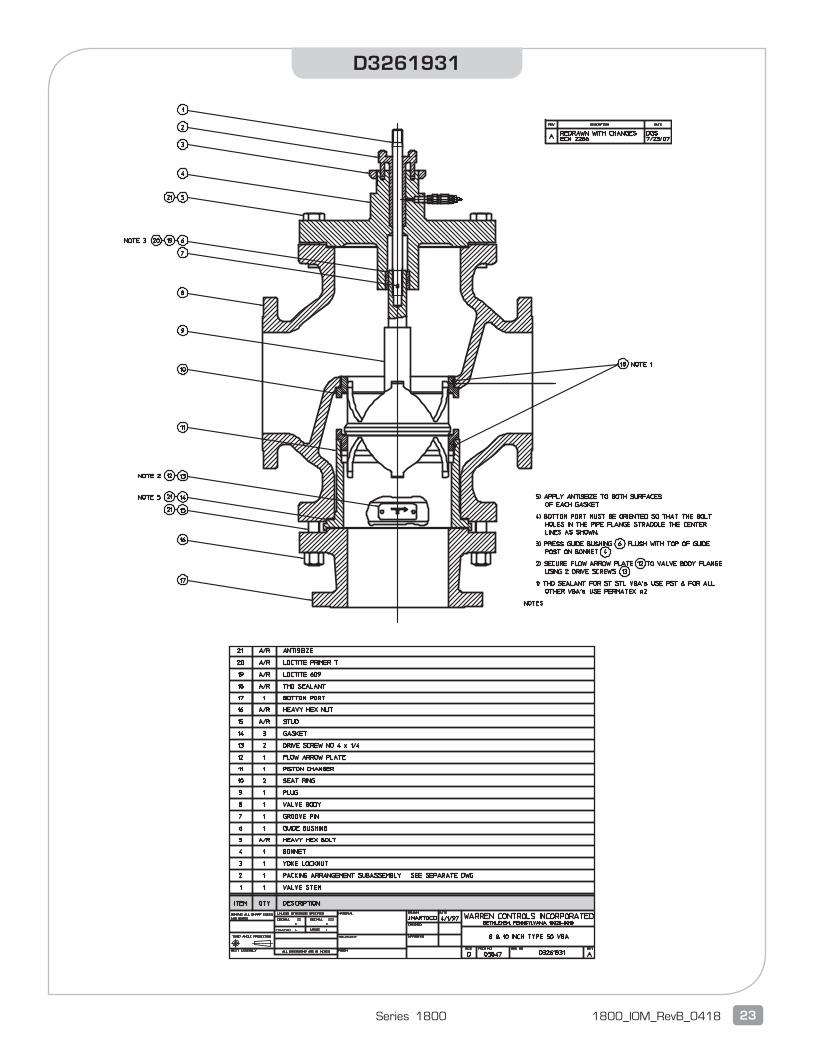
REPACK/INSPECTION KITFOR MODEL 18J VALVE TYPE 50 SIZE 800 & 010 (8 & 10 inch)SEE DWG D3261931
ITEM QTY DESCRIPTION ITEM OTY DESCRIPTION14 3 GASKET 1 REPACK KIT
1 TUBE ANTI-SEIZE LUBE
REBUILD/REPACK KITFOR MODEL 18J VALVE TYPE 50 SIZE 800 & 010 (8 & 10 inch)SEE DWG D3261931
ITEM QTY DESCRIPTION ITEM OTY DESCRIPTION1 1 VALVE STEM 14 3 GASKET7 1 GROOVE PIN 18 1 TUBE THREAD SEALANT9 1 PLUG 1 TUBE ANTI-SEIZE LUBE
10 2 SEAT RING 1 REPACK KIT
REPACK/INSPECTION KITFOR MODEL 18H VALVE TYPE 52 SIZE 300 & 400 (3 & 4 inch)SEE DWG D3261532
ITEM QTY DESCRIPTION ITEM OTY DESCRIPTION16 3 GASKET 1 REPACK KIT
1 TUBE ANTI-SEIZE LUBE
REBUILD/REPACK KITFOR MODEL 18H VALVE TYPE 52 SIZE 300 & 400 (3 & 4 inch)SEE DWG D3261532
ITEM QTY DESCRIPTION ITEM OTY DESCRIPTION1 1 VALVE STEM 12 2 SEAT RING7 2 COTTER PIN 16 3 GASKET8 2 HEX THICK SLOTTED NUT 18 1 TUBE O-RING LUBE9 1 PISTON 19 1 TUBE THREAD SEALANT
10 1 O-RING 1 TUBE ANTI-SEIZE LUBE11 1 PISTON GUIDE 1 REPACK KIT
REPACK/INSPECTION KITFOR MODEL 18J VALVE TYPE 52 SIZE 800 & 010 (8 & 10 inch)SEE DWG D3261930
ITEM QTY DESCRIPTION ITEM OTY DESCRIPTION1 4 GASKET 1 REPACK KIT
1 TUBE ANTI-SEIZE LUBE
REBUILD/REPACK KITFOR MODEL 18J VALVE TYPE 52 SIZE 800 & 010 (8 & 10 inch)SEE DWG D3261930
ITEM QTY DESCRIPTION ITEM OTY DESCRIPTION1 1 VALVE STEM 13 2 SEAT RING6 2 COTTER PIN 17 4 GASKET8 2 HEX THICK SLOTTED NUT 21 1 TUBE THREAD SEALANT9 1 PISTON 22 1 TUBE O-RING LUBE
10 2 O-RING 1 TUBE ANTI-SEIZE LUBE11 2 PISTON SEAL 1 REPACK KIT12 1 PISTON GUIDE

16 2600 Emrick Blvd • Bethlehem, PA 18020 • USA • 800-922-0085 • www.warrencontrols.com 1800_IOM_RevB_0418
C3762002

17Series 1800 1800_IOM_RevB_0418
C3762003

18 2600 Emrick Blvd • Bethlehem, PA 18020 • USA • 800-922-0085 • www.warrencontrols.com 1800_IOM_RevB_0418
D3241930

19Series 1800 1800_IOM_RevB_0418
D3241932

20 2600 Emrick Blvd • Bethlehem, PA 18020 • USA • 800-922-0085 • www.warrencontrols.com 1800_IOM_RevB_0418
D3260831

21Series 1800 1800_IOM_RevB_0418
D3261531

22 2600 Emrick Blvd • Bethlehem, PA 18020 • USA • 800-922-0085 • www.warrencontrols.com 1800_IOM_RevB_0418
D3261930
23Series 1800 1800_IOM_RevB_0418
D3261931

2600 EMRICK BLVD • BETHLEHEM, PA 18020 • USA •800-922-0085 • WWW.WARRENCONTROLS.COMDEPENDABLE, RUGGED, PRECISION CONTROL VALVES AND ACCESSORIES
1800_IOM_RevB_0418