Embed Size (px)
Citation preview

Note: The Following Manual contains an Addendum for all Series 1 and Series 1 Pro 3D Printers sold after June 2015.The Addendum applies to the following machines:
- All Series 1 Pro 3D Printers (Serial No. 10000+)- Series 1 3D Printers (Serial No. 2000+)
Before reading the addendum, please read the Quick Start Guide that came with your machine. If you need another copy of the Quick Start Guide, you can download it from our website:
http://www.typeamachines.com/pages/downloads/

SERIES 1USER MANUALTYPE A MACHINES
Type A Machines Inc.
©2014 Type A Machines Inc.This document is licenced by Creative Commons
Attribution-NonCommercial-ShareAlike (CC BY-NC-SA)
Users are free to remix, tweak, and build upon this work for non-commercial
use, as long as users credit Type A Machines Inc. and license their new
creations under the identical terms.
Every effort has been made to ensure that the information contained in this
manual is accurate. Type A Machines is not responsible for printing or clerical
errors.
Type A Machines926 Howard St.San Francisco, CA 94103www.typeamachines.com
Products in this manual may be covered by US and International Patents.
Type A Machines is a registered trademark of Type A Machines Inc. Any
products names mentioned in this manual are the property of their respective
parties.
V1.1
08.02.14
2014 Series 1 User Manual | Version 1.2
2014 Series 1 3D Printer
User Manual
Welcome to the Type A Machines family of creators. We’re excited about helping professionals, educators and individuals like yourself create amazing things that support your success. This user manual will help you get up and running quickly. You will also find resources online to dive in more deeply, applications to build and print your own 3D models, and models to download. Enabling you to go from idea to physical object is our goal. We encourage you to share your creations and give us input online at:
http://forum.typeamachines.com/ We can’t wait to see what you create. Happy printing! Espen Sivertsen, CEO
Type A Machines
typeamachines.com 0

2014 Series 1 User Manual | Version 1.2
Contents
1 Box Contents .................................................................................................................................. 2
2 About Your Series 1 ....................................................................................................................... 3
3 Getting Started ............................................................................................................................... 4
3.1 Unpacking Your Printer ........................................................................................................ 4
3.2 Attach the Side Panels, Spool Holder, and Build Platform .............................................. 4
3.3 Connect to Ethernet and Power On ................................................................................... 8
3.4 Load Filament ........................................................................................................................ 7
3.5 Connect to the Web Interface ............................................................................................. 8
3.6 Verifying and Calibrating the Z Height ............................................................................... 9
3.7 Verifying Build Platform Alignment .................................................................................. 11
3.8 Apply the Build Surface Treatment ................................................................................... 11
3.9 Time to Test Print! ............................................................................................................... 11
4 Wi-Fi Set Up .................................................................................................................................. 13
5 Software Setup ............................................................................................................................. 13
5.1 Slicing software.................................................................................................................... 14
5.2 Loading a GCode File .......................................................................................................... 14
6 Removing a Printed Object from the Print Surface ................................................................ 15
7 Prepare for Your Next Print ....................................................................................................... 15
8 File Type Basics: .STL and GCode .............................................................................................. 15
9 Customer Support ....................................................................................................................... 16
typeamachines.com 1
2014 Series 1 User Manual | Version 1.2
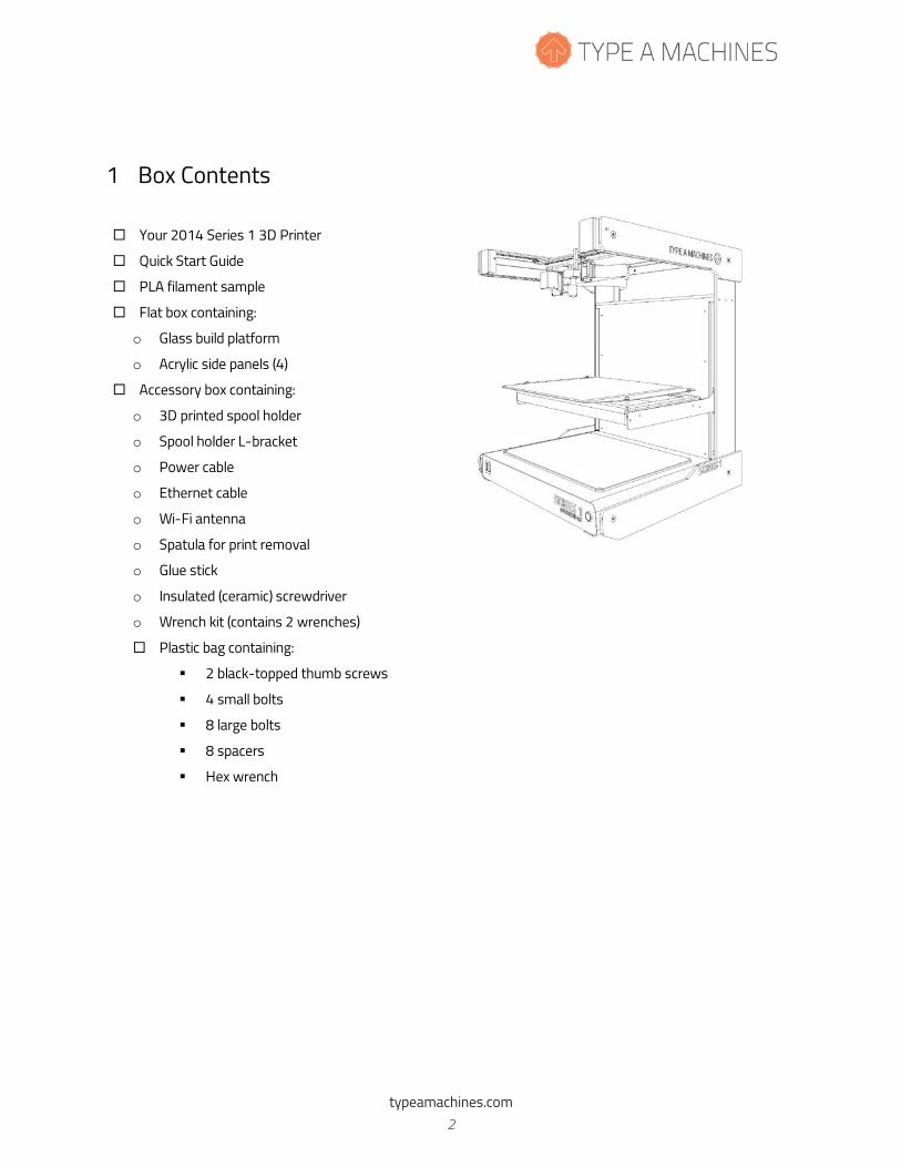
1 Box Contents
� Your 2014 Series 1 3D Printer
� Quick Start Guide
� PLA filament sample
� Flat box containing:
o Glass build platform
o Acrylic side panels (4)
� Accessory box containing:
o 3D printed spool holder
o Spool holder L-bracket
o Power cable
o Ethernet cable
o Wi-Fi antenna
o Spatula for print removal
o Glue stick
o Insulated (ceramic) screwdriver
o Wrench kit (contains 2 wrenches)
� Plastic bag containing:
� 2 black-topped thumb screws
� 4 small bolts
� 8 large bolts
� 8 spacers
� Hex wrench
typeamachines.com 2
2014 Series 1 User Manual | Version 1.2
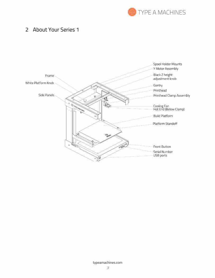
2 About Your Series 1
typeamachines.com 3
2014 Series 1 User Manual | Version 1.2
3 Getting Started
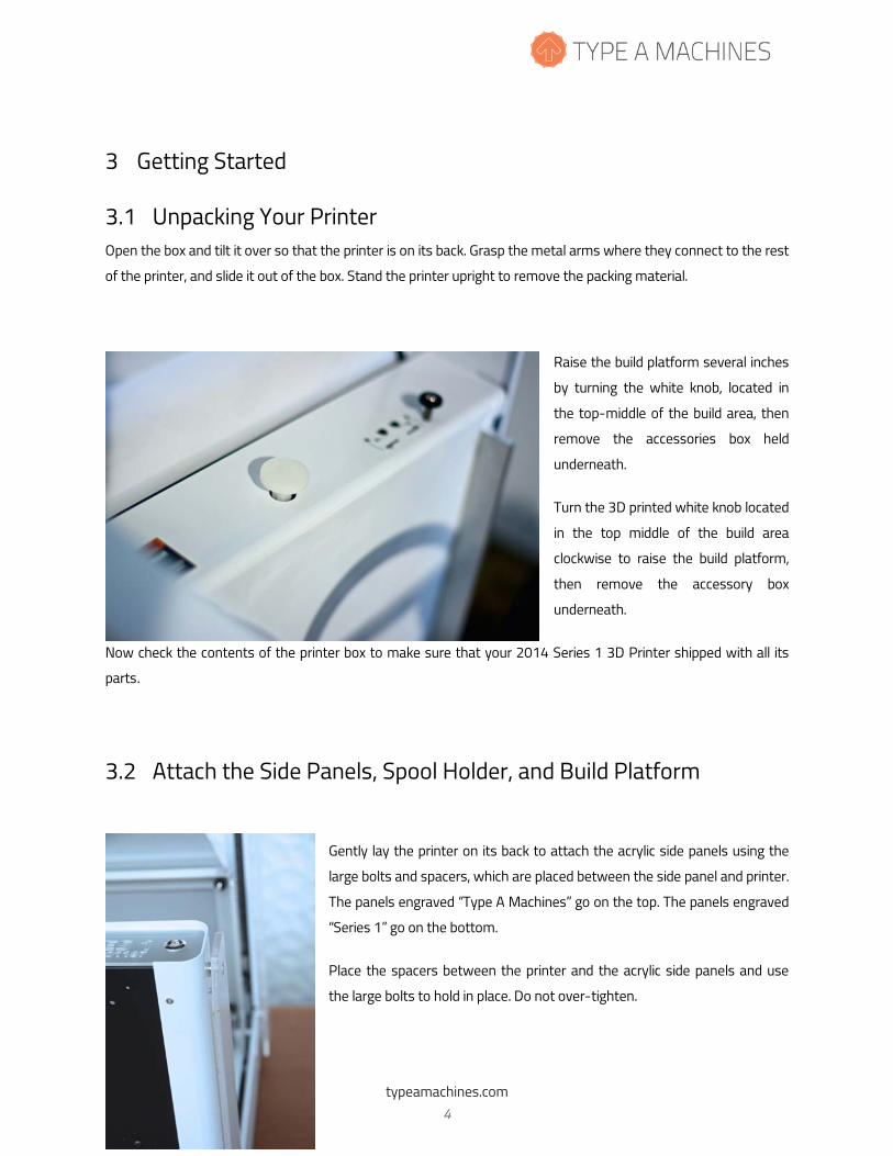
3.1 Unpacking Your Printer Open the box and tilt it over so that the printer is on its back. Grasp the metal arms where they connect to the rest
of the printer, and slide it out of the box. Stand the printer upright to remove the packing material.
Raise the build platform several inches
by turning the white knob, located in
the top-middle of the build area, then
remove the accessories box held
underneath.
Turn the 3D printed white knob located
in the top middle of the build area
clockwise to raise the build platform,
then remove the accessory box
underneath.
Now check the contents of the printer box to make sure that your 2014 Series 1 3D Printer shipped with all its
parts.
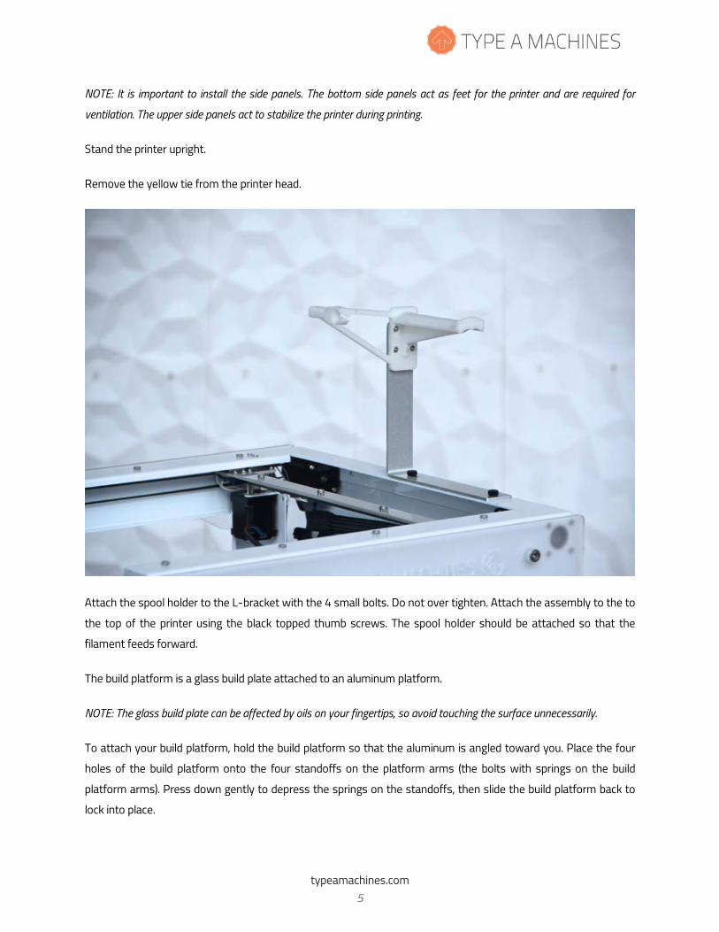
3.2 Attach the Side Panels, Spool Holder, and Build Platform
Gently lay the printer on its back to attach the acrylic side panels using the
large bolts and spacers, which are placed between the side panel and printer.
The panels engraved “Type A Machines” go on the top. The panels engraved
“Series 1” go on the bottom.
Place the spacers between the printer and the acrylic side panels and use
the large bolts to hold in place. Do not over-tighten.
typeamachines.com 4
2014 Series 1 User Manual | Version 1.2
NOTE: It is important to install the side panels. The bottom side panels act as feet for the printer and are required for
ventilation. The upper side panels act to stabilize the printer during printing.
Stand the printer upright.
Remove the yellow tie from the printer head.
Attach the spool holder to the L-bracket with the 4 small bolts. Do not over tighten. Attach the assembly to the to
the top of the printer using the black topped thumb screws. The spool holder should be attached so that the
filament feeds forward.
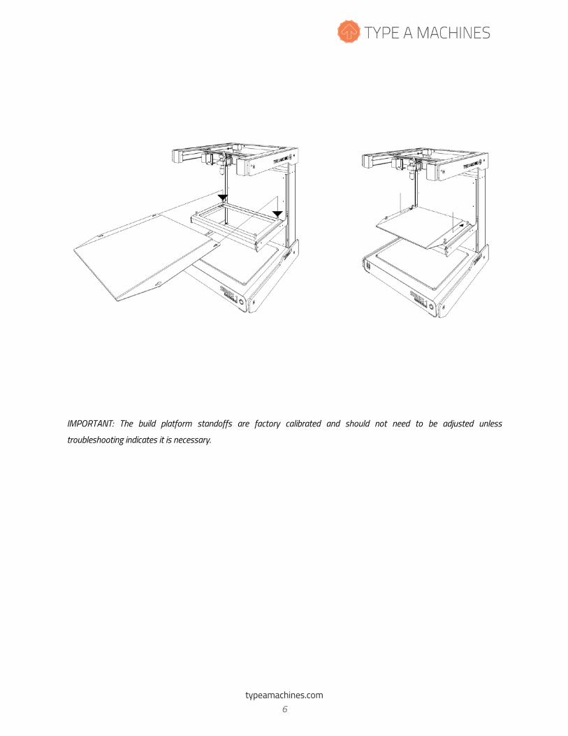
The build platform is a glass build plate attached to an aluminum platform.
NOTE: The glass build plate can be affected by oils on your fingertips, so avoid touching the surface unnecessarily.
To attach your build platform, hold the build platform so that the aluminum is angled toward you. Place the four
holes of the build platform onto the four standoffs on the platform arms (the bolts with springs on the build
platform arms). Press down gently to depress the springs on the standoffs, then slide the build platform back to
lock into place.
typeamachines.com 5
2014 Series 1 User Manual | Version 1.2
IMPORTANT: The build platform standoffs are factory calibrated and should not need to be adjusted unless
troubleshooting indicates it is necessary.
typeamachines.com 6
2014 Series 1 User Manual | Version 1.2
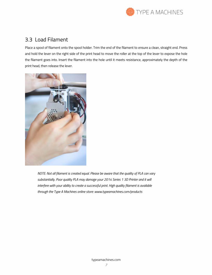
3.3 Load Filament Place a spool of filament onto the spool holder. Trim the end of the filament to ensure a clean, straight end. Press
and hold the lever on the right side of the print head to move the roller at the top of the lever to expose the hole
the filament goes into. Insert the filament into the hole until it meets resistance, approximately the depth of the
print head, then release the lever.
NOTE: Not all filament is created equal. Please be aware that the quality of PLA can vary
substantially. Poor quality PLA may damage your 2014 Series 1 3D Printer and it will
interfere with your ability to create a successful print. High quality filament is available
through the Type A Machines online store: www.typeamachines.com/products
typeamachines.com 7
2014 Series 1 User Manual | Version 1.2
3.4 Connect to Ethernet and Power On Your printer comes with two methods of connection: Ethernet (connecting to a router or base station) and wireless (Wi-Fi) networking. For initial set up you must use an Ethernet connection.
Attach the power cord and Wi-Fi antenna, then connect the printer via Ethernet cable to your router or Wi-Fi base
station. Ensure that the button on the front panel is not depressed, then turn on the power using the power
switch on the back of the printer. Before powering on your new printer, the Ethernet cable must be connected to
the printer and either a router or Wi-Fi base station in order for the printer to configure its network.
IMPORTANT: To stop all printer activity immediately, depress the lit button on the front panel of your Series 1 printer. To
begin using your printer again, press the button again to return it to its normal state. Then click the Connect button in your
printer’s web interface (read more below) to resume using your printer.
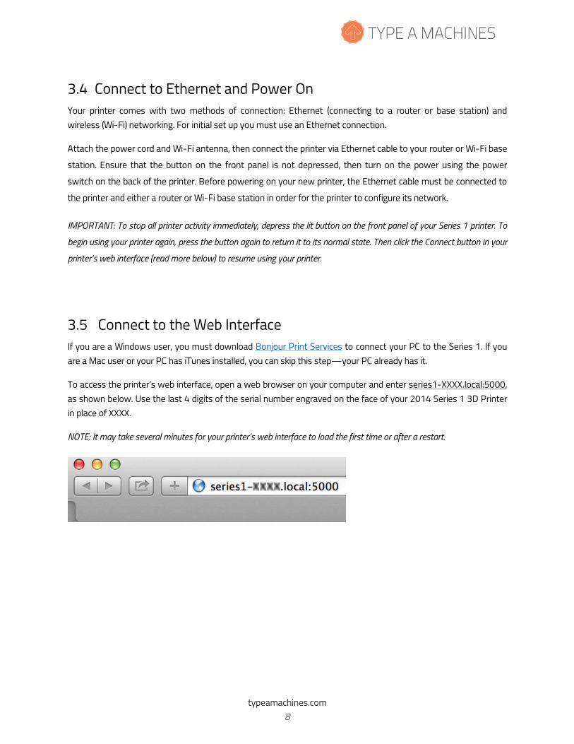
3.5 Connect to the Web Interface If you are a Windows user, you must download Bonjour Print Services to connect your PC to the Series 1. If you are a Mac user or your PC has iTunes installed, you can skip this step—your PC already has it.
To access the printer’s web interface, open a web browser on your computer and enter series1-XXXX.local:5000, as shown below. Use the last 4 digits of the serial number engraved on the face of your 2014 Series 1 3D Printer in place of XXXX.
NOTE: It may take several minutes for your printer’s web interface to load the first time or after a restart.
typeamachines.com 8
2014 Series 1 User Manual | Version 1.2
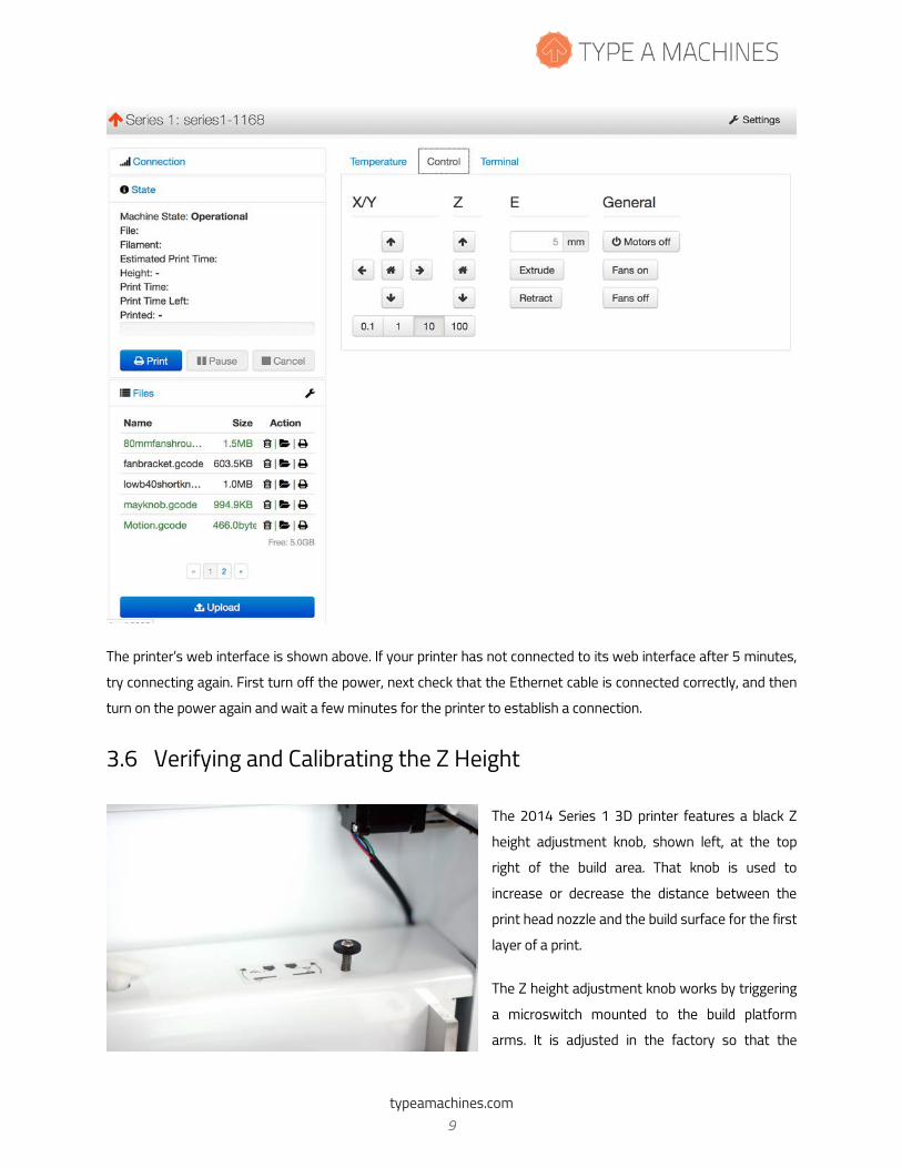
The printer’s web interface is shown above. If your printer has not connected to its web interface after 5 minutes,
try connecting again. First turn off the power, next check that the Ethernet cable is connected correctly, and then
turn on the power again and wait a few minutes for the printer to establish a connection.
3.6 Verifying and Calibrating the Z Height
The 2014 Series 1 3D printer features a black Z
height adjustment knob, shown left, at the top
right of the build area. That knob is used to
increase or decrease the distance between the
print head nozzle and the build surface for the first
layer of a print.
The Z height adjustment knob works by triggering
a microswitch mounted to the build platform
arms. It is adjusted in the factory so that the
typeamachines.com 9
2014 Series 1 User Manual | Version 1.2
switch is triggered when the build surface is just below the tip of the print head nozzle.
CAUTION: Before checking the Z height, make sure the print head is cool. Failure to ensure the print head is cool may
result in damage to the machine.
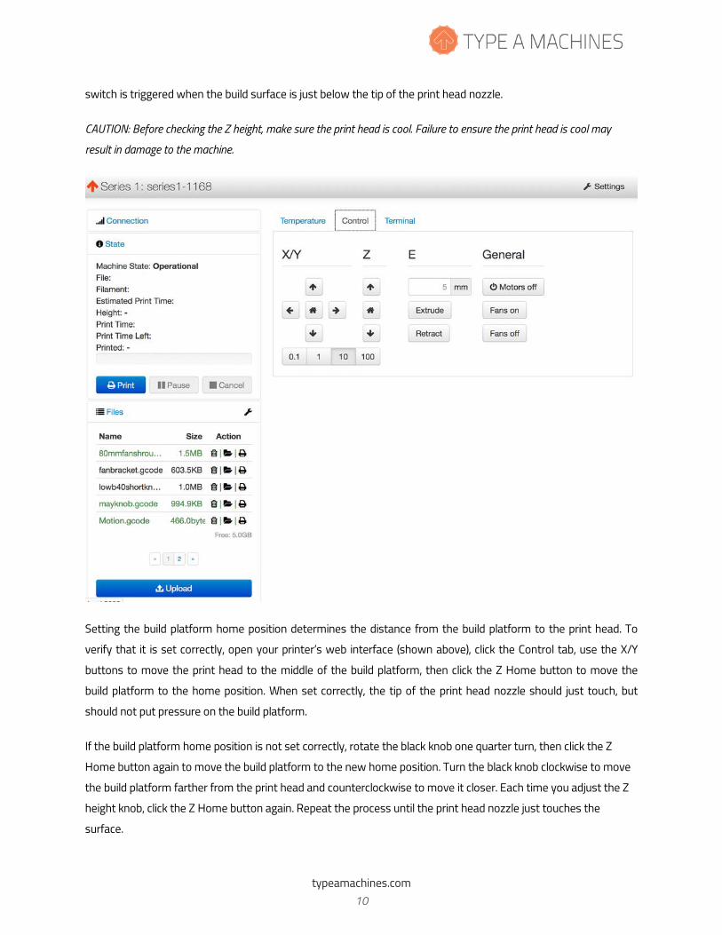
Setting the build platform home position determines the distance from the build platform to the print head. To
verify that it is set correctly, open your printer’s web interface (shown above), click the Control tab, use the X/Y
buttons to move the print head to the middle of the build platform, then click the Z Home button to move the
build platform to the home position. When set correctly, the tip of the print head nozzle should just touch, but
should not put pressure on the build platform.
If the build platform home position is not set correctly, rotate the black knob one quarter turn, then click the Z
Home button again to move the build platform to the new home position. Turn the black knob clockwise to move
the build platform farther from the print head and counterclockwise to move it closer. Each time you adjust the Z
height knob, click the Z Home button again. Repeat the process until the print head nozzle just touches the
surface.
typeamachines.com 10
2014 Series 1 User Manual | Version 1.2
3.7 Verifying Build Platform Alignment The build platform is calibrated to be parallel to the print head during manufacturing, but shifting may occur during shipping.
Use the X and Y buttons on the Control tab of the web interface to move the print head to each corner of the build surface to verify your build platform is aligned with the print head. If not, see “Aligning the Build Platform” in the Troubleshooting section of the Type A Machines web page.
3.8 Apply the Build Surface Treatment The glass square is your build surface. In order to prepare the surface for printing, open the included glue stick and
apply a thin layer across the platform. Allow the glue to dry to the touch before printing.
You may be able to print several times before replacing the build surface treatment. At some point, however,
portions of the printed object will no longer stick to the surface. When this happens, rinse the dried glue from the
build surface, let it dry, and reapply the glue using the included glue stick.
You may wish to vary your level of adhesion based on your print type. For general use the included glue stick
works well. For more delicate prints, stronger adhesion, or easier removal, try 3M 2093-EL 2” wide blue painter’s
tape.
To use blue painter’s tape, cut a length of tape about 12 inches long, align it with the bottom of the glass build
surface. Place each subsequent length of tape edge to the edge along side the tape already placed on the build
surface. Do not overlap the tape. Repeat this process until the glass build surface is covered with tape. Use the
print removal spatula to ensure there are no bubbles or voids. Avoid touching the tape where you will be printing
as the oils from your fingers may affect adhesion.
3.9 Time to Test Print! Choose the file “FirstPrint.gcode” from the files at the bottom left of the printer’s web interface. All files listed
there are included with your printer. Click the Print icon to the right of the file you select.
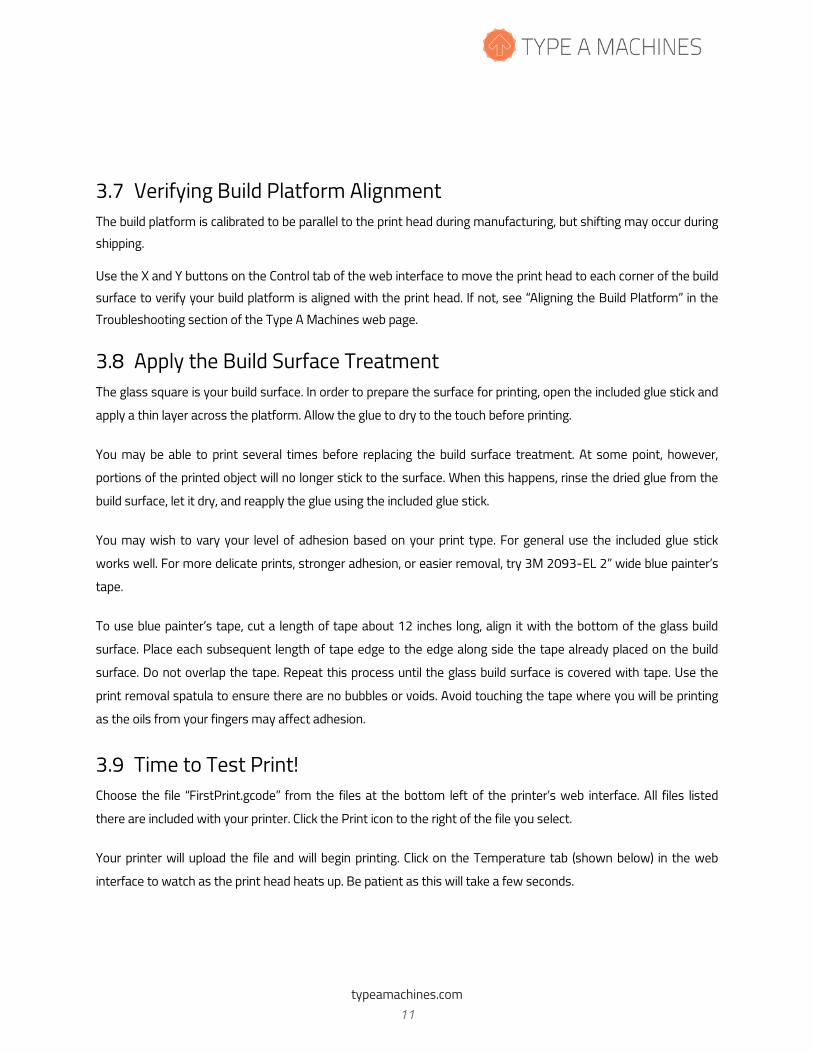
Your printer will upload the file and will begin printing. Click on the Temperature tab (shown below) in the web
interface to watch as the print head heats up. Be patient as this will take a few seconds.
typeamachines.com 11
2014 Series 1 User Manual | Version 1.2
CAUTION: The print head is hot and you may burn yourself if you touch it or newly extruded filament.
If your GCode is set to extrude filament prior to starting the print, you can manually remove this extra filament
with the print removal spatula, or allow it to be wiped off on the build surface. The print head will then begin
creating your print.
The front fan will remain off while printing the first few layers. The fan should turn on later to help solidify the
printed part. The rear fan is always on when the print head is above 50˚ Celsius.
typeamachines.com 12
2014 Series 1 User Manual | Version 1.2
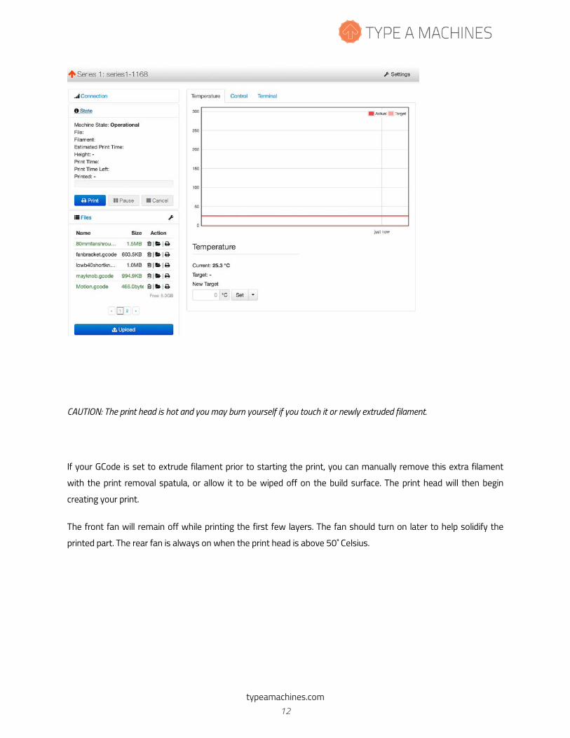
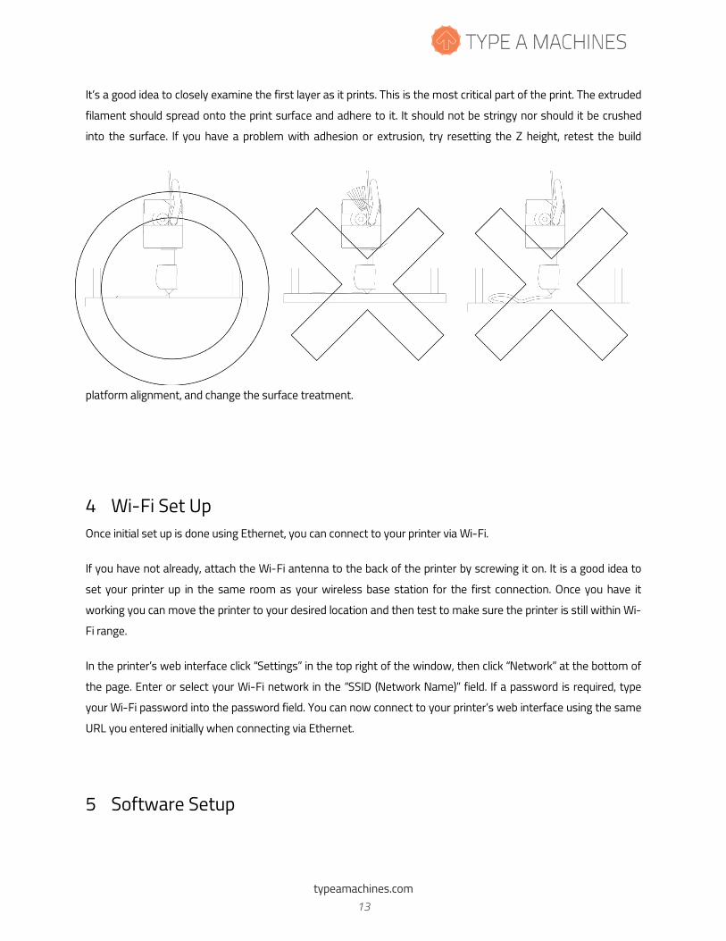
It’s a good idea to closely examine the first layer as it prints. This is the most critical part of the print. The extruded
filament should spread onto the print surface and adhere to it. It should not be stringy nor should it be crushed
into the surface. If you have a problem with adhesion or extrusion, try resetting the Z height, retest the build
platform alignment, and change the surface treatment.
4 Wi-Fi Set Up Once initial set up is done using Ethernet, you can connect to your printer via Wi-Fi.
If you have not already, attach the Wi-Fi antenna to the back of the printer by screwing it on. It is a good idea to
set your printer up in the same room as your wireless base station for the first connection. Once you have it
working you can move the printer to your desired location and then test to make sure the printer is still within Wi-
Fi range.
In the printer’s web interface click “Settings” in the top right of the window, then click “Network” at the bottom of
the page. Enter or select your Wi-Fi network in the “SSID (Network Name)” field. If a password is required, type
your Wi-Fi password into the password field. You can now connect to your printer’s web interface using the same
URL you entered initially when connecting via Ethernet.
5 Software Setup
typeamachines.com 13
2014 Series 1 User Manual | Version 1.2
5.1 Slicing software To begin printing your own designs to your 2014 Series 1 3D Printer you will need to install a slicing engine. This is
the program that takes the model information from your CAD program and converts it into machine readable code
(also known as GCode) to tell the printer what to do.
There is a slicer software installation package with settings for your 2014 Series 1 3D Printer embedded and
additional test models that are available for download on our website. Select the link for the Operating System
you are running and download.
Go to typeamachines.cm/download to get your installer package.
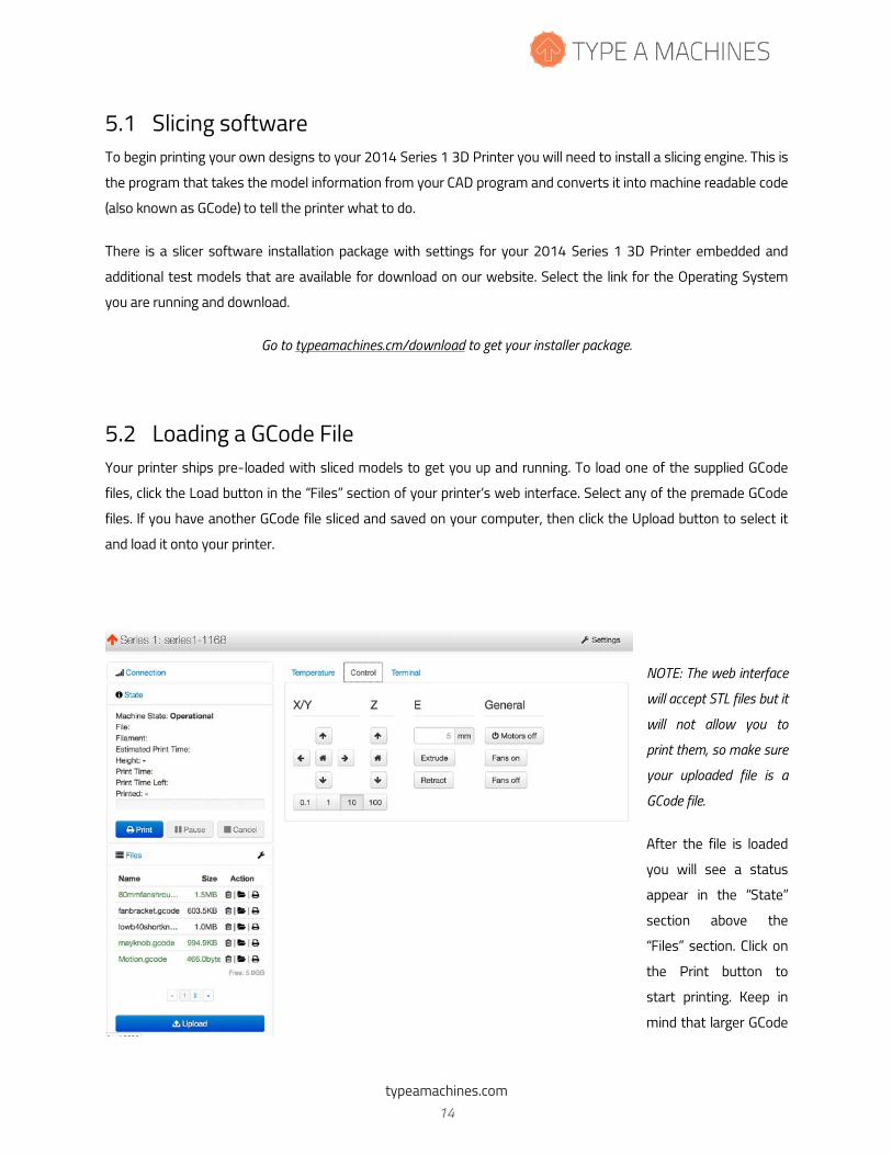
5.2 Loading a GCode File Your printer ships pre-loaded with sliced models to get you up and running. To load one of the supplied GCode
files, click the Load button in the “Files” section of your printer’s web interface. Select any of the premade GCode
files. If you have another GCode file sliced and saved on your computer, then click the Upload button to select it
and load it onto your printer.
NOTE: The web interface
will accept STL files but it
will not allow you to
print them, so make sure
your uploaded file is a
GCode file.
After the file is loaded
you will see a status
appear in the “State”
section above the
“Files” section. Click on
the Print button to
start printing. Keep in
mind that larger GCode
typeamachines.com 14
2014 Series 1 User Manual | Version 1.2
files will take longer to upload.
6 Removing a Printed Object from the Print Surface When your 3D print completes, the print head will move to the back of the machine. Most of the time you will be
able to gently pry your print off the surface using the included print removal spatula. If your finished part does not
come off easily, after the machine has cooled you can quickly and easily take out the build platform to remove the
printed object. This is particularly useful for prints with a large footprint.
To do this, first grasp the sides of the build platform. Press down gently to depress the standoff springs, then
gently slide the build platform towards you to detach it from the bolts.
Once the build platform has been removed from the machine, it is easier to work the print removal spatula all the
way around the printed object in order to separate it from the build platform.
If your printed object will not separate from the build platform, take it to a sink and run warm water around the
print to loosen the glue. Use the print removal spatula to work warm water under the print. Once your print is
loose, you should be able to gently pull the rest of it off of the print surface.
NOTE: This water method of print removal should be used instead of applying force, which may crack the glass on the
build platform. Be patient and let the warm water work. If you crack the glass a replacement can be ordered from the
accessories area of the typeamachines.com web store.
7 Prepare for Your Next Print You may be able to print multiple times before your surface treatment will need to be replaced. In order to
promote good adhesion of the initial print layer, avoid touching the build surface with your fingers so as not to
transfer oils to the build surface. If subsequent prints do not attach to the print surface well, replace the build
surface treatment.
8 File Type Basics: .STL and GCode The first step in the process from your 3D model to making a 3D print is to export your 3D model from your
modeling program as an .STL file. STL is an industry standard for 3D printing files. Your model must be a closed,
typeamachines.com 15
2014 Series 1 User Manual | Version 1.2
water-tight mesh. This is critical to producing a quality print. There are many software modeling tools and mesh
repair utilities you can use for this.
We have included a few premade GCode files on your printer and also in the slicer download package so you can
get printing right out of the gate.
The 2014 Series 1 3D Printer reads instructions about how to move the print head and build platform and when
to extrude filament from a file called a GCode file. GCode is produced by “slicing” software. GCode files end in
“.gcode” or “.gco.” GCode files are specific for each type of printer. When you slice a 3D file, you need to make sure
that your slicer software is using settings specifically for the 2014 Series 1 3D Printer. Otherwise the resulting
GCode will not communicate correctly to your printer.
9 Customer Support If you’re having trouble getting a print to run smoothly, or you haven’t been able to find answers to your questions
in this manual, the next place to look is at the videos and knowledge base articles found in our product support
area at www.support.typeamachines.com/hc/en-us.
If you do not find what you need there, please visit our community forum at www.forum.typeamachines.com.
Type A Machines is privileged to have an active, well informed, and helpful community on our forums. The forum is
also one of our favorite places to announce product giveaways, betas, and competitions. Finally, it’s also a great
place for you to show off your awesome prints and machine modifications.
Enjoy your new printer and welcome to the Type A Machines community!
typeamachines.com 16
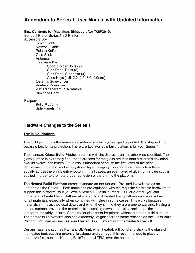
Box Contents for Machines Shipped after 7/25/2015: Series 1 Pro or Series 1 3D Printer Accessory Box Power Cable Network Cable Palette Knife Glue Stick Antenna Hardware Bag Spool Holder Bolts (2) Side Panel Bolts (8) Side Panel Standoffs (8) Allen Keys (1.5, 2.0, 2.5, 3.0, 4.0mm) Ceramic Screwdriver Printer’s Wrenches 20ft Transparent PLA Sample Business Card
Flatpack Build Platform Side Panels (4)
Addendum to Series 1 User Manual with Updated Information
Hardware Changes to the Series 1
The Build Platform
The build platform is the removable surface on which your object is printed. It is shipped in a separate box for its protection. There are two available build platforms for your Series 1.
The standard Glass Build Platform comes with the Series 1, unless otherwise specified. The glass surface is extremely flat - the tolerances for the glass are less than a micron’s deviation over its twelve inch length. Flat glass is important because the first layer of the print (sometimes thought of as the “keystone” layer to signify its importance) needs to adhere equally across the print’s entire footprint. In all cases, an even layer of glue from a glue stick is applied in order to promote proper adhesion of the print to the platform.
The Heated Build Platform comes standard on the Series 1 Pro, and is available as an upgrade on the Series 1. Both machines are equipped with the requisite electronic hardware to support this platform, so if you own a Series 1, (Serial number 2000 or greater) you can upgrade to a heated build platform at a later date. A heated build platform improves adhesion for all materials, especially when combined with glue in some cases. This works because materials shrink as they cool down, and when they shrink, they are prone to warping. Having a heated surface prevents the materials from cooling down too quickly, and keeps the temperatures fairly uniform. Some materials cannot be printed without a heated build platform. The heated build platform also has extremely flat glass for the same reasons as the Glass Build Platform. You can always use your Heated Build Platform with the heater turned off.
Certain materials such as PET and BluPrint, when heated, will bond and stick to the glass of the heated bed, causing potential breakage and damage. It is recommended to place a protective film, such as Kapton, BuildTak, or ULTEM, over the heated bed.
Indicator LEDs
The Series 1’s toolhead status can be easily ascertained by looking at the lights on the print head. The blue light indicates that the machine is powered on, and that there is power going to the print head. The green light is part of the fan circuit, and will only be on when the front cooling fan is also on. The read light is part of the thermal circuit is only on when there is electricity running through the heater. You will notice that during your print, the red light will alternate between being on and off in no particular pattern. This is normal. The hot end is kept hot by sending pulses of energy to maintain a requested temperature. If the heater was always on, then the hot end would continue to get warmer until a failure occurred. The same mathematical principals used here are also used by thermostats.
Universal Spool Holder
This version of the Series 1 comes with a new spool holder and a guide tube that goes between the spool holder and the toolhead. It is unique in that it can accommodate almost any sized spool. Refer to the Quick Start Guide which came with your Series 1, and which is also available online for download, for installation instructions.
Other Hardware Changes
WhisperDrive. We have upgraded the electronics to a much newer stepper driver system. The newer stepper drivers are, as the name suggests, are nearly silent. In informal tests done in our lab, where there was standard office conversation nearby, the Series 1 equipped with WhisperDrive did not register on our acoustic equipment. In addition, the new electronics have interpolated 1/256th microstepping. This means that the size of the artifacts that appear on some prints, especially ones optimized for speed over quality, are automatically 16 times less noticeable.
Upgraded Networking Systems. The machine now has a networking device that is capable of generating its own wireless networks in lieu of connecting to one. If you power on your Series 1, and it is unable to connect to any known Wi-Fi network, it will automatically generate its own access point. From there you can connect your computer to it, and if you choose, using the web interface, configure your Series 1’s Wi-Fi connection just as you would on your computer.
Heavy Duty Power and Signal Transmission Systems On-Board. The Series 1 is equipped with cabling systems that are tested to over one million cycles. In scientifically defined torture tests in our lab, we have been unable to cause a failure under above-normal operating circumstances. If your cables do break, they are both under warranty, and easily replaceable.
Stiffer Frame. Since this manual was originally published, stiffeners have been upgraded and added to the machines X and Z axes to make the machine stiffer and more robust. The most dramatic improvement comes to the X axis, which is now stiffer by multiple orders of magnitude.
Heated Bed Ready. Even if your Series 1 did not come with a heated bed, all machines sold after July 2015, or with serial numbers 2000 (Series 1) or 10000 (Series 1 Pro) and above, include the internal power distribution hardware to support a heated bed. Please note that if your bed heats up when you first turn on your machine or under any circumstance where it has been commanded to be off, turn off your machine and contact technical support.
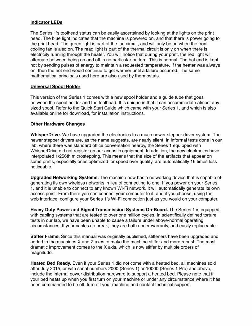
Status Indicators Print status, errors, and progress
Visualizer Live cam view (if equipped) or 3D
model render
Wi-Fi Settings Wi-Fi network selection, Access
Point mode
Settings General printer settings
Tabs Files: File upload and
management, Cone file
Temperature: Print Head, heated
bed controls
Control: Direct Print Head control,
HomeTerminal: Command-line
interface
A
B
C
D
E
The Series 1 Web Interface
A
D
E
C
B
What else can you expect from the Series 1 Interface?
Status at a GlanceUsing the redesigned onboard control software, you can get a complete readout of your machine's status, from the filename and progress of your print, to the temperature of the hot end and optional heated build platform.
Wi-Fi Access Point ModeThe Series 1, when powered on, will automatically connect to a familiar Wi-Fi network with no configuration required. But unlike other Wi-Fi enabled devices, if it cannot connect automatically, it will generate it's own access point which you can use to start prints and control the machine. Because the web interface includes a Wi-Fi configuration wizard, connecting the Series 1 to a wireless network is as easy as doing so on your computer.
Monitor and Examine Your Prints From AnywhereThe Series 1 features an optional webcam that allows you to record your print's progress as a timelapse or monitor its progress through the web interface.
Stay Up-To-Date. Automatically.The onboard software interface receives OTA updates, allowing you to have the latest and greatest software as soon as it becomes available.
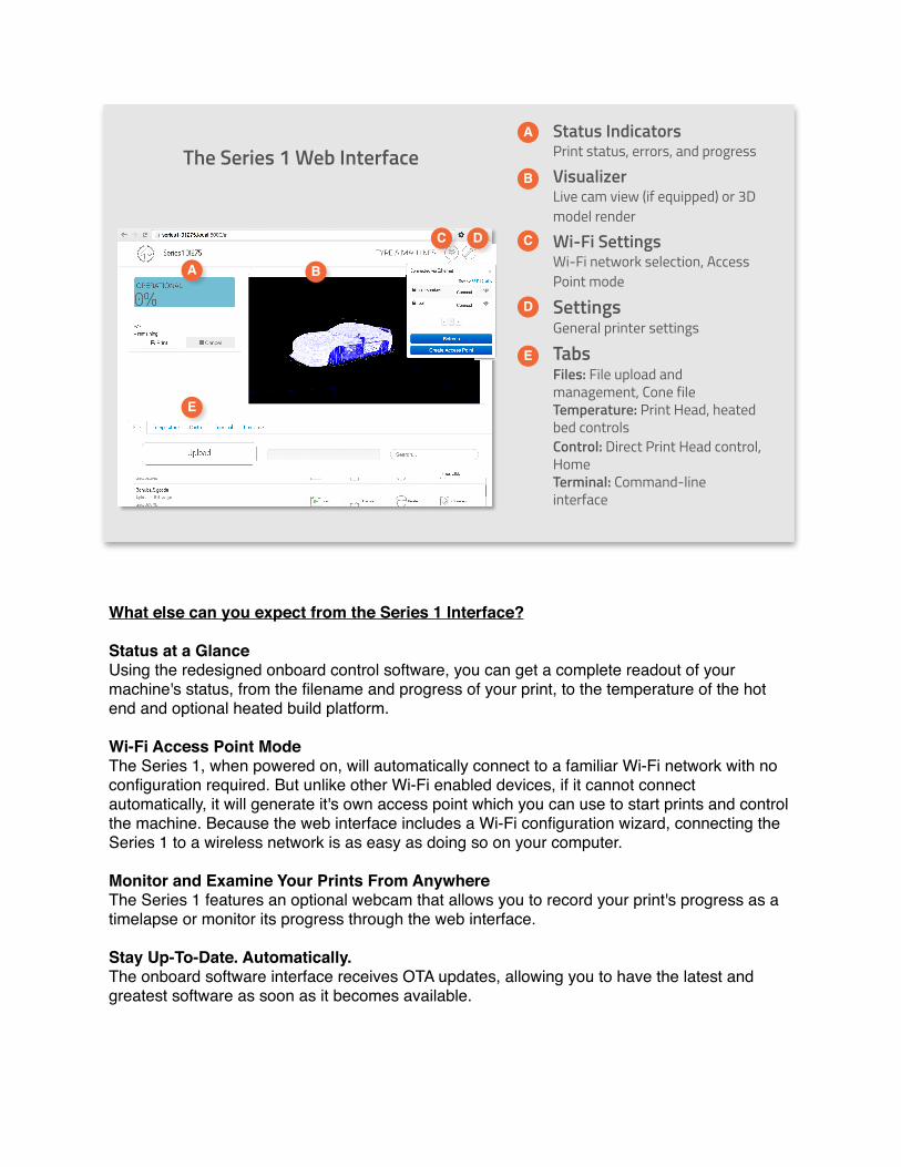
Real-Time Monitoring
One of the most exciting new features for the Series 1 Pro is the real-time monitoring and timelapse recording that is available. The webcam can be activated for real-time monitoring, simply by clicking on the webcam icon as depicted below. It may take a moment to load.
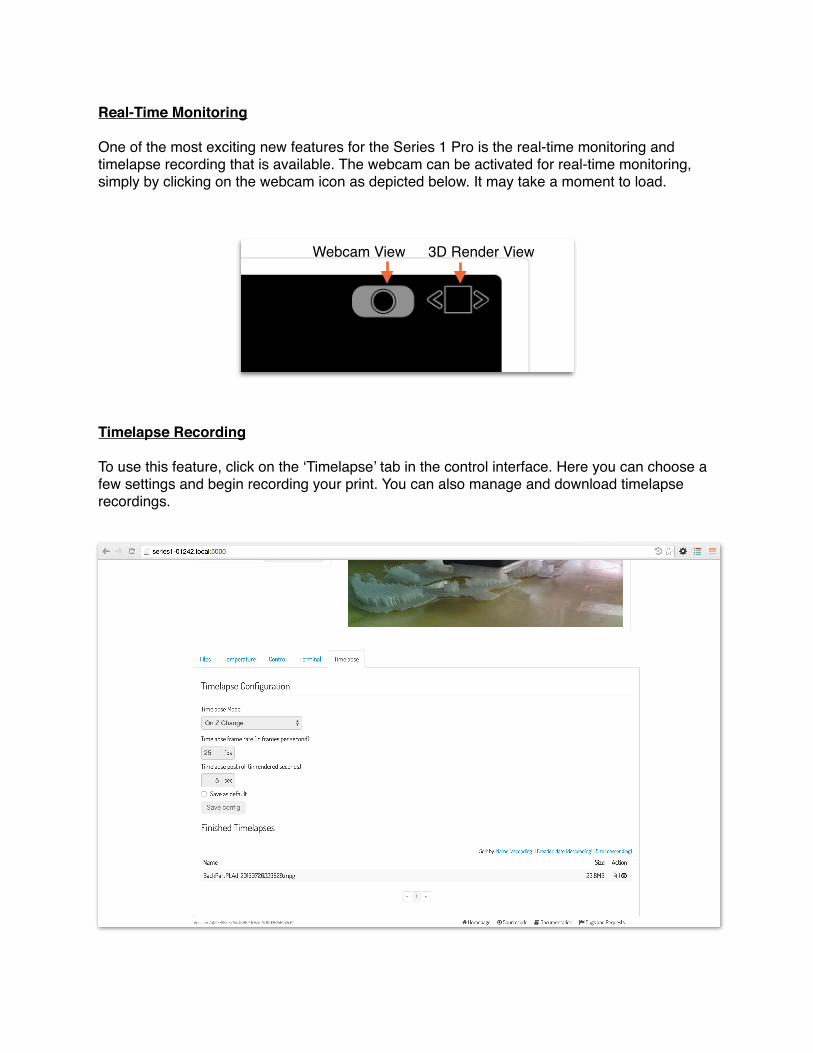
Timelapse Recording
To use this feature, click on the ‘Timelapse’ tab in the control interface. Here you can choose a few settings and begin recording your print. You can also manage and download timelapse recordings.
Webcam View 3D Render View
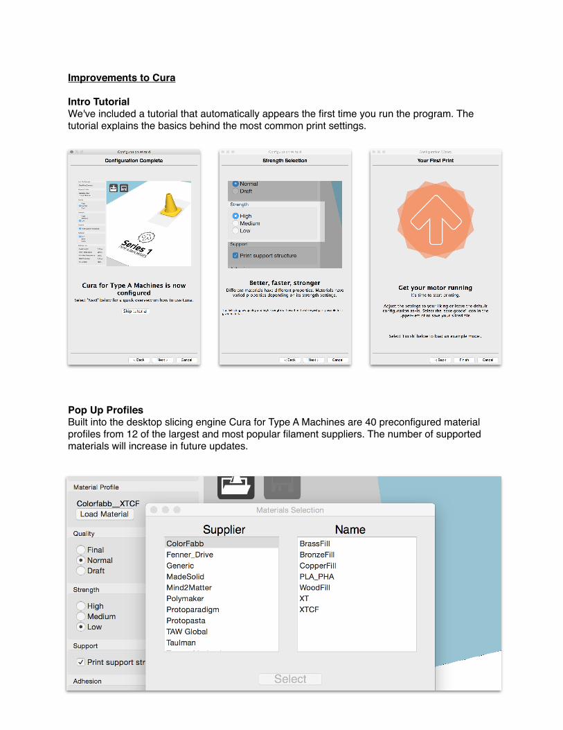
Improvements to Cura
Intro TutorialWe've included a tutorial that automatically appears the first time you run the program. The tutorial explains the basics behind the most common print settings.
Pop Up ProfilesBuilt into the desktop slicing engine Cura for Type A Machines are 40 preconfigured material profiles from 12 of the largest and most popular filament suppliers. The number of supported materials will increase in future updates.