Embed Size (px)
Citation preview
Agilent E5100A/B Network Analyzer
HP Instrument BASIC Users
Handbook Supplement
SERIAL NUMBERS
This manual applies directly to instruments with serial
number pre�x JP1KC,JP2KC,JP3KC,JP4KC,JP5KC,MY405.
For additional important information about serial numbers,
read \Serial Number" in Appendix A of this Manual.
Agilent Part No. E5100-90025Printed in JAPAN July 2001
Fourth Edition
Notice
The information contained in this document is subject to change without notice.
This document contains proprietary information that is protected by copyright. All rights are
reserved. No part of this document may be photocopied, reproduced, or translated to another
language without the prior written consent of the Agilent Technologies.
Agilent Technologies Japan, Ltd.
Component Test PGU-Kobe
1-3-2, Murotani, Nishi-ku, Kobe-shi,
Hyogo, 651-2241 Japan
c Copyright 1995, 1996, 2000, 2001 Agilent Technologies Japan, Ltd.
Manual Printing History
The manual printing date and part number indicate its current edition. The printing date
changes when a new edition is printed. (Minor corrections and updates that are incorporated
at reprint do not cause the date to change.) The manual part number changes when extensive
technical changes are incorporated.
November, 1995 : : : : : : : : : : : : : : : : : : : : : : : : : : : : : : : : : : : : : First Edition (part number: E5100-90005)
March, 1996 : : : : : : : : : : : : : : : : : : : : : : : : : : : : : : : : : : : : : : :Second Edition (part number: E5100-90015)
March 2000 : : : : : : : : : : : : : : : : : : : : : : : : : : : : : : : : : : : : : : : : : Third Edition (part number: E5100-90015)
July 2001 : : : : : : : : : : : : : : : : : : : : : : : : : : : : : : : : : : : : : : : : : : Fourth Edition (part number: E5100-90025)
iii
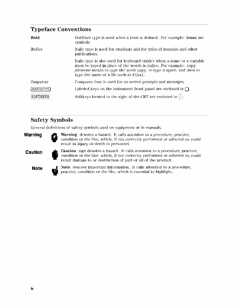
Typeface Conventions
Bold Boldface type is used when a term is de�ned. For example: icons aresymbols.
Italics Italic type is used for emphasis and for titles of manuals and other
publications.
Italic type is also used for keyboard entries when a name or a variable
must be typed in place of the words in italics. For example: copy
�lename means to type the word copy, to type a space, and then to
type the name of a �le such as file1.
Computer Computer font is used for on-screen prompts and messages.
�HARDKEYS� Labeled keys on the instrument front panel are enclosed in � �.NNNNNNNNNNNNNNNNNNNNNNNNNNSOFTKEYS Softkeys located to the right of the CRT are enclosed in
NNNNN.
Safety Symbols
General de�nitions of safety symbols used on equipment or in manuals.
Warning denotes a hazard. It calls attention to a procedure, practice,
condition or the like, which, if not correctly performed or adhered to, could
result in injury or death to personnel.
Caution sign denotes a hazard. It calls attention to a procedure, practice,
condition or the like, which, if not correctly performed or adhered to, could
result damage to or destruction of part or all of the product.
Note denotes important information. It calls attention to a procedure,
practice, condition or the like, which is essential to highlight.
iv
Contents
1. IntroductionBrief Description of HP Instrument BASIC . . . . . . . . . . . . . . . . . . . 1-1
Using This Manual . . . . . . . . . . . . . . . . . . . . . . . . . . . . . . 1-2
2. Quick StartUsing HP Instrument BASIC . . . . . . . . . . . . . . . . . . . . . . . . . 2-1
Connecting the Keyboard . . . . . . . . . . . . . . . . . . . . . . . . . 2-1
Allocating Screen Area for HP Instrument BASIC . . . . . . . . . . . . . . 2-1
Editing a Program . . . . . . . . . . . . . . . . . . . . . . . . . . . . . 2-2
Running the Program . . . . . . . . . . . . . . . . . . . . . . . . . . . 2-2
Listing the Program . . . . . . . . . . . . . . . . . . . . . . . . . . . . 2-3
Saving Programs . . . . . . . . . . . . . . . . . . . . . . . . . . . . . . 2-3
Listing File Names . . . . . . . . . . . . . . . . . . . . . . . . . . . . . 2-3
Getting Programs . . . . . . . . . . . . . . . . . . . . . . . . . . . . . 2-4
For More Information . . . . . . . . . . . . . . . . . . . . . . . . . . . . 2-4
3. Analyzer Speci�c HP Instrument BASIC FeaturesPower On Auto-start Program . . . . . . . . . . . . . . . . . . . . . . . . . 3-1
Display Allocation . . . . . . . . . . . . . . . . . . . . . . . . . . . . . . 3-1
Run Light Indications . . . . . . . . . . . . . . . . . . . . . . . . . . . 3-2
Mass Storage . . . . . . . . . . . . . . . . . . . . . . . . . . . . . . . . 3-3
Storage Unit . . . . . . . . . . . . . . . . . . . . . . . . . . . . . . . . 3-3
Storage Format . . . . . . . . . . . . . . . . . . . . . . . . . . . . . . 3-3
Initialize . . . . . . . . . . . . . . . . . . . . . . . . . . . . . . . . 3-3
Graphics . . . . . . . . . . . . . . . . . . . . . . . . . . . . . . . . . . 3-4
HP Instrument BASIC Graphics Commands . . . . . . . . . . . . . . . . . 3-4
Initial settings . . . . . . . . . . . . . . . . . . . . . . . . . . . . . . . 3-5
External RUN/CONT Connector . . . . . . . . . . . . . . . . . . . . . . . . 3-5
I/O Interfaces and Select Codes . . . . . . . . . . . . . . . . . . . . . . . . 3-5
4. Analyzer Speci�c HP Instrument BASIC CommandsBASIC Commands Not Implemented . . . . . . . . . . . . . . . . . . . . . . 4-1
BASIC Commands Speci�c to E5100A/B . . . . . . . . . . . . . . . . . . . . 4-1
DATE . . . . . . . . . . . . . . . . . . . . . . . . . . . . . . . . . . . . 4-2
DATE$ . . . . . . . . . . . . . . . . . . . . . . . . . . . . . . . . . . . 4-4
READIO . . . . . . . . . . . . . . . . . . . . . . . . . . . . . . . . . . . 4-5
SET TIME . . . . . . . . . . . . . . . . . . . . . . . . . . . . . . . . . . 4-6
SET TIMEDATE . . . . . . . . . . . . . . . . . . . . . . . . . . . . . . . 4-7
TIME . . . . . . . . . . . . . . . . . . . . . . . . . . . . . . . . . . . . 4-8
TIME$ . . . . . . . . . . . . . . . . . . . . . . . . . . . . . . . . . . . 4-9
WRITEIO . . . . . . . . . . . . . . . . . . . . . . . . . . . . . . . . . . 4-10
Contents-1
A. Manual ChangesIntroduction . . . . . . . . . . . . . . . . . . . . . . . . . . . . . . . . . A-1
Manual Changes . . . . . . . . . . . . . . . . . . . . . . . . . . . . . . . A-1
Instruments Covered by This Manual . . . . . . . . . . . . . . . . . . . . . A-2
B. KeyboardCharacter Entry Keys . . . . . . . . . . . . . . . . . . . . . . . . . . . . B-1
Cursor-Control and Display-Control Keys . . . . . . . . . . . . . . . . . . . B-2
Numeric Keypad . . . . . . . . . . . . . . . . . . . . . . . . . . . . . . . B-2
Editing Keys . . . . . . . . . . . . . . . . . . . . . . . . . . . . . . . . B-2
Softkeys . . . . . . . . . . . . . . . . . . . . . . . . . . . . . . . . . . B-2
Index
Contents-2
Figures
1-1. HP Instrument BASIC System . . . . . . . . . . . . . . . . . . . . . . . . 1-1
2-1. Connecting a Keyboard . . . . . . . . . . . . . . . . . . . . . . . . . . 2-1
3-1. Display Allocation . . . . . . . . . . . . . . . . . . . . . . . . . . . . . 3-2
3-2. Screen Structure . . . . . . . . . . . . . . . . . . . . . . . . . . . . . . 3-4
3-3. RUN/CONT Trigger Signal . . . . . . . . . . . . . . . . . . . . . . . . . 3-5
A-1. Serial Number Plate (Sample) . . . . . . . . . . . . . . . . . . . . . . . . A-2
B-1. Softkey Menus for HP Instrument BASIC . . . . . . . . . . . . . . . . . . B-3
Tables
A-1. Manual Changes by Serial Number . . . . . . . . . . . . . . . . . . . . . A-1
A-2. Manual Changes by Firmware Version . . . . . . . . . . . . . . . . . . . . A-1
Contents-3

1
Introduction
This supplement provides a brief description of HP Instrument BASIC and an introduction to its
use.
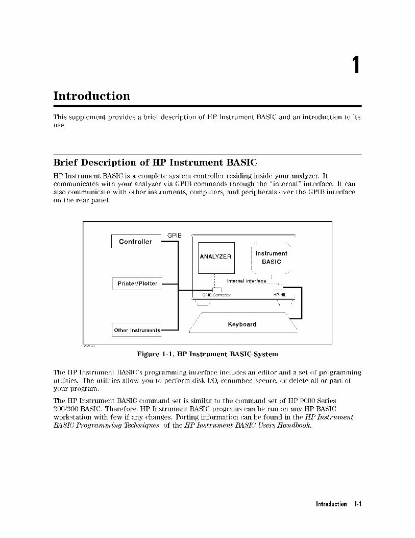
Brief Description of HP Instrument BASIC
HP Instrument BASIC is a complete system controller residing inside your analyzer. It
communicates with your analyzer via GPIB commands through the \internal" interface. It can
also communicate with other instruments, computers, and peripherals over the GPIB interface
on the rear panel.
Figure 1-1. HP Instrument BASIC System
The HP Instrument BASIC's programming interface includes an editor and a set of programming
utilities. The utilities allow you to perform disk I/O, renumber, secure, or delete all or part of
your program.
The HP Instrument BASIC command set is similar to the command set of HP 9000 Series
200/300 BASIC. Therefore, HP Instrument BASIC programs can be run on any HP BASIC
workstation with few if any changes. Porting information can be found in the HP Instrument
BASIC Programming Techniques of the HP Instrument BASIC Users Handbook.
Introduction 1-1
Using This Manual
This supplement is not intended to teach you the HP Instrument BASIC programming language
nor to learn how to operate the E5100A/B. You should became familiar with the operation of
the analyzer and the BASIC programming language before attempting to control the analyzer
using HP Instrument BASIC. If you are not familiar with HP Instrument BASIC, see chapters 1
and 2 and appendix B before trying to use it.
The organization of this supplement is described below.
Chapter 1. Introduction
This chapter provides a brief description of HP Instrument BASIC and how to use this
manual.
Chapter 2. Quick Start
This chapter provides information on how to edit, run, save, and load the program on HP
Instrument BASIC. This chapter is useful if you are new user of HP Instrument BASIC.
Chapter 3. Analyzer Speci�c HP Instrument BASIC Features
This chapter summarizes the unique features speci�ed for the analyzer.
Chapter 4. Analyzer Speci�c HP Instrument BASIC Commands
This chapter provides de�nitions for BASIC commands speci�c to the analyzer's HP
Instrument BASIC.
Appendix A. Manual Changes
This appendix contains the information required to adapt this manual to earlier versions or
con�gurations of the analyzer than the current printing date of this manual.
Appendix B. External Keyboard
This appendix provides a reference guide to the analyzer's HP Instrument BASIC's key
de�nitions for the keyboard.
1-2 Introduction
2
Quick Start
This chapter provides a quick start guide for using HP Instrument BASIC. A new user can
become familiar with HP Instrument BASIC by performing these procedures.
Using HP Instrument BASIC
The following pages show how to use HP Instrument BASIC by writing, executing, listing,
saving, and getting programs.
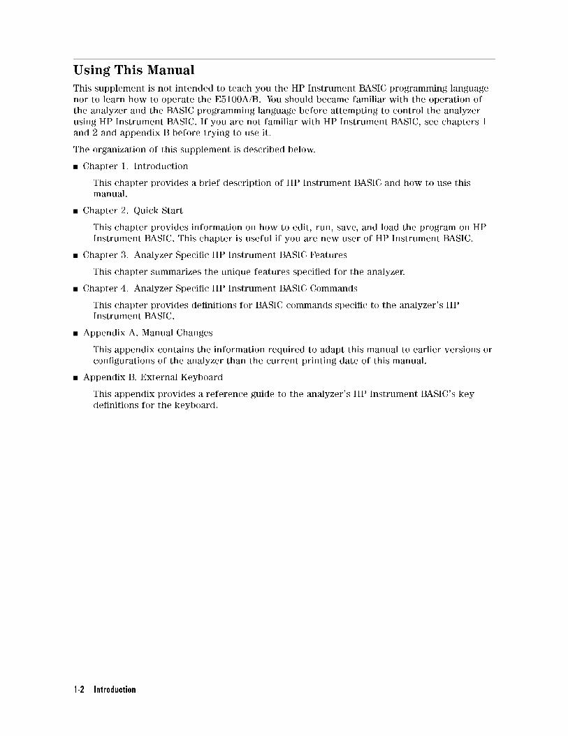
Connecting the Keyboard
Connect the furnished keyboard to the keyboard connector on the rear panel as shown in
Figure 2-1.
Figure 2-1. Connecting a Keyboard
Allocating Screen Area for HP Instrument BASIC
Because all of the analyzer's screen is allocated for analyzer operation after power ON, you
must allocate screen area for HP Instrument BASIC when you want to use it.
1. Press �Display�NNNNNNNNNNNNNNNNNNNNNNNNNNNNNNNNNNNNNNNNNNNNNNNNNNNNNNNNDISPLAY ALLOCATION .
2. Verify theNNNNNNNNNNNNNNNNNNNNNNNNNNNNNNNNNNNNNNNNNNNNALL INSTRUMENT is underlined.
3. Select your required softkey in the following keys.NNNNNNNNNNNNNNNNNNNNNNNNNNNNNNNNNNNNNNNNNNNNNNNNNNNNNNNNNNNNNNNNNHALF INSTR HALF BASIC Two half-screens with one graticule display above the HP
Instrument BASIC display.
Quick Start 2-1
NNNNNNNNNNNNNNNNNNNNNNNNNNNNNALL BASIC The full screen is allocated for the HP Instrument BASIC
Display.NNNNNNNNNNNNNNNNNNNNNNNNNNNNNNNNNNNNNNBASIC STATUS A full screen graticule with three status lines for HP
Instrument BASIC under the graticule.
Editing a Program
When you edit a program, you must be in the EDIT mode.
1. Enter the EDIT mode.
From keyboard
Type EDIT �Enter�
From front panel
Press �System�NNNNNNNNNNNNNNNNNNNNIBASIC
NNNNNNNNNNNNNNEdit
2. Verify that the cursor appears at line number 10.
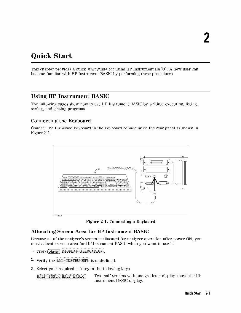
3. Type the program. For example:
d a
10 ASSIGN @Hpe5100 TO 800
20 CLEAR @Hpe5100
30 OUTPUT @Hpe5100;"INST CH2"
40 OUTPUT@Hpe5100;"INST:STAT ON"
50 END
This program makes the channel 2 activate.
4. Exit the EDIT mode.
From keyboard
Press �Esc� or �Pause�
From front panel
Press �System�NNNNNNNNNNNNNNNNNNNNIBASIC
NNNNNNNNNNNNNNNNNNNNNNNNNNEND EDIT
Running the Program
After writing the program, run the program as follows:
From keyboard
Type RUN �Enter� or �F10�
From front panel
Press �System�NNNNNNNNNNNNNNNNNNNNIBASIC
NNNNNNNNNNNRun
2-2 Quick Start
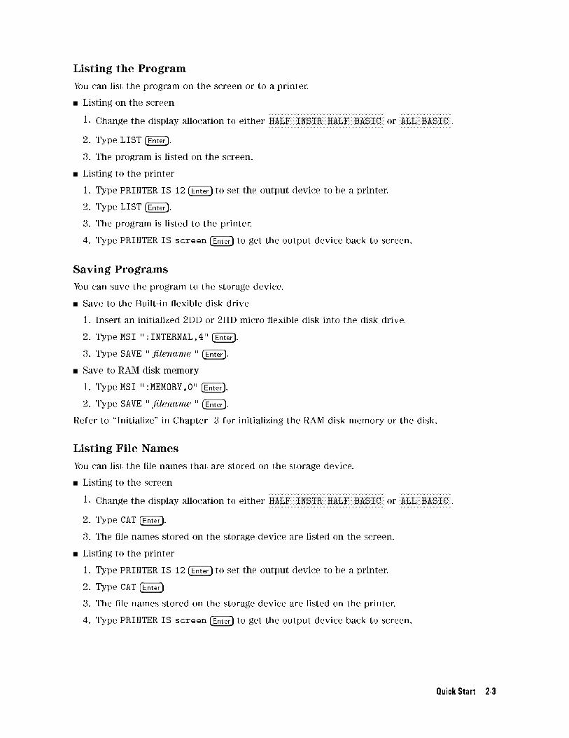
Listing the Program
You can list the program on the screen or to a printer.
Listing on the screen
1. Change the display allocation to eitherNNNNNNNNNNNNNNNNNNNNNNNNNNNNNNNNNNNNNNNNNNNNNNNNNNNNNNNNNNNNNNNNNHALF INSTR HALF BASIC or
NNNNNNNNNNNNNNNNNNNNNNNNNNNNNALL BASIC .
2. Type LIST �Enter�.
3. The program is listed on the screen.
Listing to the printer
1. Type PRINTER IS 12 �Enter� to set the output device to be a printer.
2. Type LIST �Enter�.
3. The program is listed to the printer.
4. Type PRINTER IS screen �Enter� to get the output device back to screen.
Saving Programs
You can save the program to the storage device.
Save to the Built-in exible disk drive
1. Insert an initialized 2DD or 2HD micro exible disk into the disk drive.
2. Type MSI ":INTERNAL,4" �Enter�.
3. Type SAVE " �lename " �Enter�.
Save to RAM disk memory
1. Type MSI ":MEMORY,0" �Enter�.
2. Type SAVE " �lename " �Enter�.
Refer to \Initialize" in Chapter 3 for initializing the RAM disk memory or the disk.
Listing File Names
You can list the �le names that are stored on the storage device.
Listing to the screen
1. Change the display allocation to eitherNNNNNNNNNNNNNNNNNNNNNNNNNNNNNNNNNNNNNNNNNNNNNNNNNNNNNNNNNNNNNNNNNHALF INSTR HALF BASIC or
NNNNNNNNNNNNNNNNNNNNNNNNNNNNNALL BASIC .
2. Type CAT �Enter�.
3. The �le names stored on the storage device are listed on the screen.
Listing to the printer
1. Type PRINTER IS 12 �Enter� to set the output device to be a printer.
2. Type CAT �Enter�
3. The �le names stored on the storage device are listed on the printer.
4. Type PRINTER IS screen �Enter� to get the output device back to screen.
Quick Start 2-3
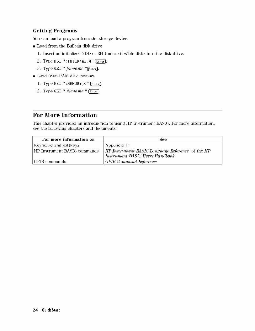
Getting Programs
You can load a program from the storage device.
Load from the Built-in disk drive
1. Insert an initialized 2DD or 2HD micro exible disks into the disk drive.
2. Type MSI ":INTERNAL,4" �Enter�.
3. Type GET " �lename "�Enter�.
Load from RAM disk memory
1. Type MSI ":MEMORY,0" �Enter�.
2. Type GET " �lename " �Enter�.
For More Information
This chapter provided an introduction to using HP Instrument BASIC. For more information,
see the following chapters and documents:
For more information on See
Keyboard and softkeys Appendix B
HP Instrument BASIC commands HP Instrument BASIC Language Reference of the HP
Instrument BASIC Users Handbook
GPIB commands GPIB Command Reference
2-4 Quick Start
3
Analyzer Speci�c HP Instrument BASIC Features
This chapter summarizes the following HP Instrument BASIC features that are speci�c to the
analyzer:
Power On Auto-start Program
Display Allocation
Mass Storage
Graphics
External RUN/CONT Connector
I/O Interface and Select Codes
Power On Auto-start Program
HP Instrument BASIC allows you to automatically load and execute a program �le named
AUTOST during power-up.
The disk on which you stored AUTOST must be inserted in the disk drive before the analyzer is
turned ON.
Display Allocation
Display allocation softkeys allocate the screen area for HP Instrument BASIC (see Figure 3-1).NNNNNNNNNNNNNNNNNNNNNNNNNNNNNNNNNNNNNNNNNNNNALL INSTRUMENT Selects a full screen single screen or two half-screen graticules.
NNNNNNNNNNNNNNNNNNNNNNNNNNNNNNNNNNNNNNNNNNNNNNNNNNNNNNNNNNNNNNNNNHALF INSTR HALF BASIC Selects two half-screens, one graticule display above the HP
Instrument BASIC display.NNNNNNNNNNNNNNNNNNNNNNNNNNNNNALL BASIC Selects a full screen single HP Instrument BASIC display.
NNNNNNNNNNNNNNNNNNNNNNNNNNNNNNNNNNNNNNBASIC STATUS Selects a full screen graticule and three status lines for HP
Instrument BASIC under the graticule.
Analyzer Speci�c HP Instrument BASIC Features 3-1
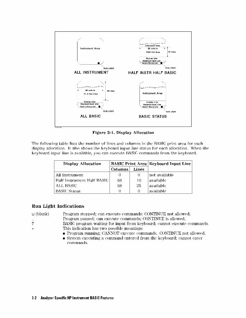
Figure 3-1. Display Allocation
The following table lists the number of lines and columns in the BASIC print area for each
display allocation. It also shows the keyboard input line status for each allocation. When the
keyboard input line is available, you can execute BASIC commands from the keyboard.
Display Allocation BASIC Print Area Keyboard Input Line
Columns Lines
All Instrument 0 0 not available
Half Instrument Half BASIC 68 10 available
ALL BASIC 68 25 available
BASIC Status 0 0 available
Run Light Indications
t (blank) Program stopped; can execute commands; CONTINUE not allowed.
Program paused; can execute commands; CONTINUE is allowed.
? BASIC program waiting for input from keyboard; cannot execute commands.
� This indication has two possible meanings:
Program running; CANNOT execute commands. CONTINUE not allowed.
System executing a command entered from the keyboard; cannot enter
commands.
3-2 Analyzer Speci�c HP Instrument BASIC Features
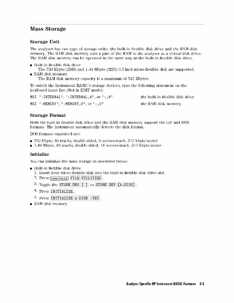
Mass Storage
Storage Unit
The analyzer has two type of storage units: the built-in exible disk drive and the RAM disk
memory. The RAM disk memory uses a part of the RAM in the analyzer as a virtual disk drive.
The RAM disk memory can be operated in the same way as the built-in exible disk drive.
Built-in exible disk drive
The 720 Kbyte (2DD) and 1.44 Mbyte (2HD) 3.5 inch micro- exible disk are supported.
RAM disk memory
The RAM disk memory capacity is a maximum of 512 Kbytes.
To switch the Instrument BASIC's storage devices, type the following statement on the
keyboard input line (Not in EDIT mode):
MSI ":INTERNAL", ":INTERNAL,4", or ":,4" the built-in exible disk drive
MSI ":MEMORY", ":MEMORY,0", or ":,0" the RAM disk memory
Storage Format
Both the built-in exible disk drive and the RAM disk memory support the LIF and DOS
formats. The instrument automatically detects the disk format.
DOS formats supported are:
720 Kbyte, 80 tracks, double-sided, 9 sectors/track, 512 kbyte/sector
1.44 Mbyte, 80 tracks, double-sided, 18 sectors/track, 512 kbyte/sector
Initialize
You can initialize the mass storage as described below:
Built-in exible disk drive
1. Insert your micro- exible disk into the built-in exible disk drive slot.
2. Press �Save/Recall�NNNNNNNNNNNNNNNNNNNNNNNNNNNNNNNNNNNNNNNNNNNNFILE UTILITIES .
3. Toggle theNNNNNNNNNNNNNNNNNNNNNNNNNNNNNNNNNNNNNNNNNSTORE DEV [ ] to
NNNNNNNNNNNNNNNNNNNNNNNNNNNNNNNNNNNNNNNNNNNNNNNNNNNNNNNNSTORE DEV [A:DISK] .
4. PressNNNNNNNNNNNNNNNNNNNNNNNNNNNNNNNNINITIALIZE .
5. PressNNNNNNNNNNNNNNNNNNNNNNNNNNNNNNNNNNNNNNNNNNNNNNNNNNNNNNNNNNNNNNNNNNNNINITIALIZE A:DISK :YES .
RAM disk memory
Analyzer Speci�c HP Instrument BASIC Features 3-3
Graphics
HP Instrument BASIC adds graphics capability to the analyzer. You can draw pictures on the
CRT display independent of the grids and traces.
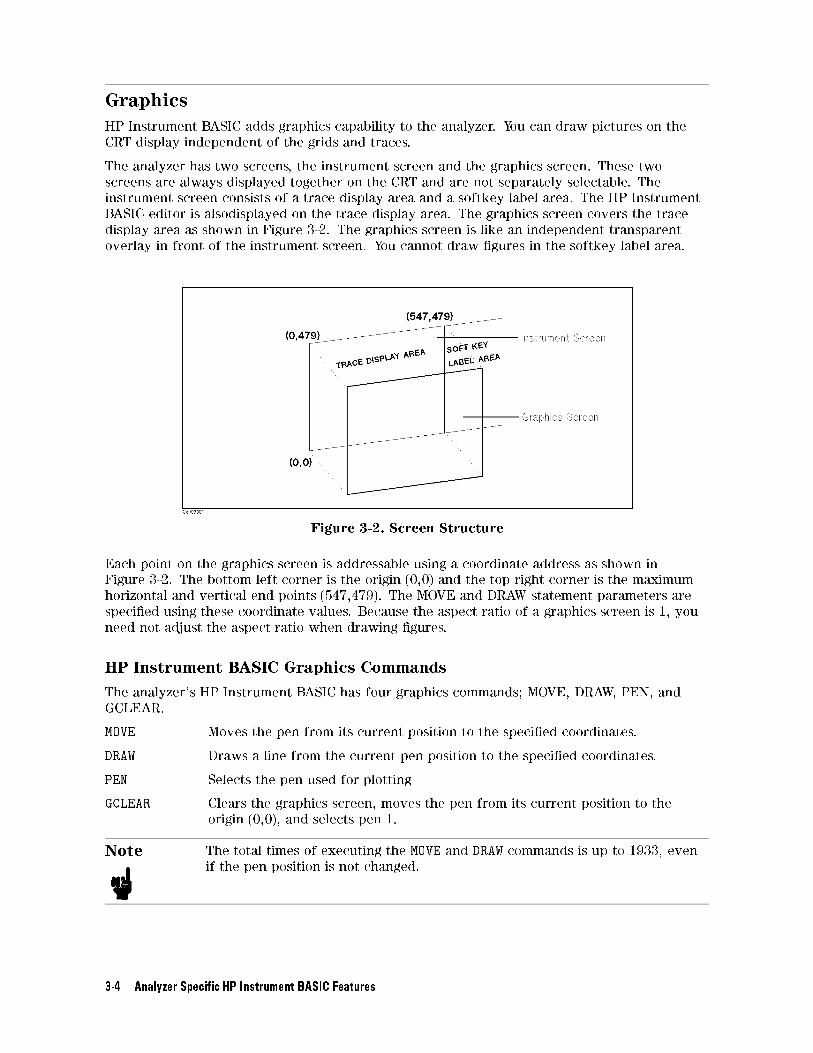
The analyzer has two screens, the instrument screen and the graphics screen. These two
screens are always displayed together on the CRT and are not separately selectable. The
instrument screen consists of a trace display area and a softkey label area. The HP Instrument
BASIC editor is alsodisplayed on the trace display area. The graphics screen covers the trace
display area as shown in Figure 3-2. The graphics screen is like an independent transparent
overlay in front of the instrument screen. You cannot draw �gures in the softkey label area.
Figure 3-2. Screen Structure
Each point on the graphics screen is addressable using a coordinate address as shown in
Figure 3-2. The bottom left corner is the origin (0,0) and the top right corner is the maximum
horizontal and vertical end points (547,479). The MOVE and DRAW statement parameters are
speci�ed using these coordinate values. Because the aspect ratio of a graphics screen is 1, you
need not adjust the aspect ratio when drawing �gures.
HP Instrument BASIC Graphics Commands
The analyzer's HP Instrument BASIC has four graphics commands; MOVE, DRAW, PEN, and
GCLEAR.
MOVE Moves the pen from its current position to the speci�ed coordinates.
DRAW Draws a line from the current pen position to the speci�ed coordinates.
PEN Selects the pen used for plotting
GCLEAR Clears the graphics screen, moves the pen from its current position to the
origin (0,0), and selects pen 1.
Note The total times of executing the MOVE and DRAW commands is up to 1933, even
if the pen position is not changed.
3-4 Analyzer Speci�c HP Instrument BASIC Features
Initial settings
When power is turned ON, the default settings are as follows:
MOVE 0,0
PEN 1
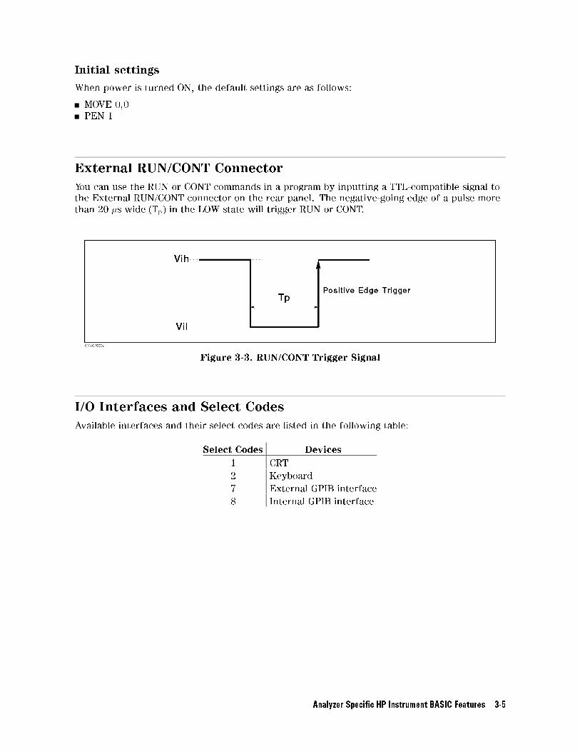
External RUN/CONT Connector
You can use the RUN or CONT commands in a program by inputting a TTL-compatible signal to
the External RUN/CONT connector on the rear panel. The negative-going edge of a pulse more
than 20 �s wide (Tp) in the LOW state will trigger RUN or CONT.
Figure 3-3. RUN/CONT Trigger Signal
I/O Interfaces and Select Codes
Available interfaces and their select codes are listed in the following table:
Select Codes Devices
1 CRT
2 Keyboard
7 External GPIB interface
8 Internal GPIB interface
Analyzer Speci�c HP Instrument BASIC Features 3-5

4Analyzer Speci�c HP Instrument BASIC
Commands
BASIC Commands Not Implemented
The following commands are listed in the HP Instrument BASIC Language Reference of the HP
Instrument Users Handbook , but not implemented in the analyzer's HP Instrument BASIC.
OFF CYCLE
ON CYCLE
Note GCLEAR and ON TIMEOUT commands are available, but the following
supplementary items are added.
GCLEAR
Move the pen to (0,0) and select pen 1.
OFF TIMEOUT and ON TIMEOUT
The interface select code is 7 only.
BASIC Commands Speci�c to E5100A/B
The following commands are not listed in the HP Instrument BASIC Language Reference of
the HP Instrument BASIC Users Handbook , but are available in the analyzer's HP Instrument
BASIC.
DATE
DATE$
READIO
SET TIME
SET TIMEDATE
TIME
TIME$
WRITEIO
Analyzer Speci�c HP Instrument BASIC Commands 4-1
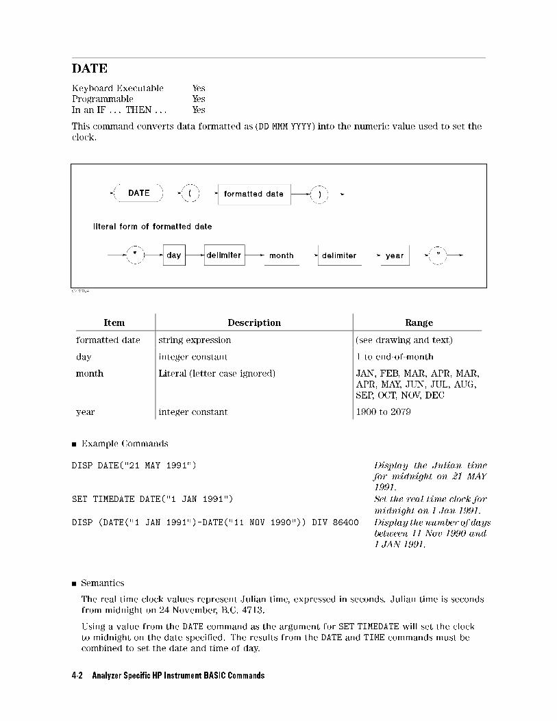
DATE
Keyboard Executable Yes
Programmable Yes
In an IF . . . THEN . . . Yes
This command converts data formatted as (DD MMM YYYY) into the numeric value used to set the
clock.
Item Description Range
formatted date string expression (see drawing and text)
day integer constant 1 to end-of-month
month Literal (letter case ignored) JAN, FEB, MAR, APR, MAR,
APR, MAY, JUN, JUL, AUG,
SEP, OCT, NOV, DEC
year integer constant 1900 to 2079
Example Commands
DISP DATE("21 MAY 1991") Display the Julian time
for midnight on 21 MAY
1991.
SET TIMEDATE DATE("1 JAN 1991") Set the real time clock for
midnight on 1 Jan 1991.
DISP (DATE("1 JAN 1991")-DATE("11 NOV 1990")) DIV 86400 Display the number of days
between 11 Nov 1990 and
1 JAN 1991.
Semantics
The real time clock values represent Julian time, expressed in seconds. Julian time is seconds
from midnight on 24 November, B.C. 4713.
Using a value from the DATE command as the argument for SET TIMEDATE will set the clock
to midnight on the date speci�ed. The results from the DATE and TIME commands must be
combined to set the date and time of day.
4-2 Analyzer Speci�c HP Instrument BASIC Commands

If the DATE command is used as an argument for SET TIMEDATE to set the clock, the date
must be in the range: 1 Mar 1900 to 4 Aug 2079.
Specifying invalid date, such as the thirty-�rst of February, will cause an error.
Leading blanks or non-numeric characters are ignored. ASCII spaces are recommended as
delimiters between the day, month and year. However, any non-alphanumeric character,
except the negative sign (�), may be used as the delimiter.
Analyzer Speci�c HP Instrument BASIC Commands 4-3
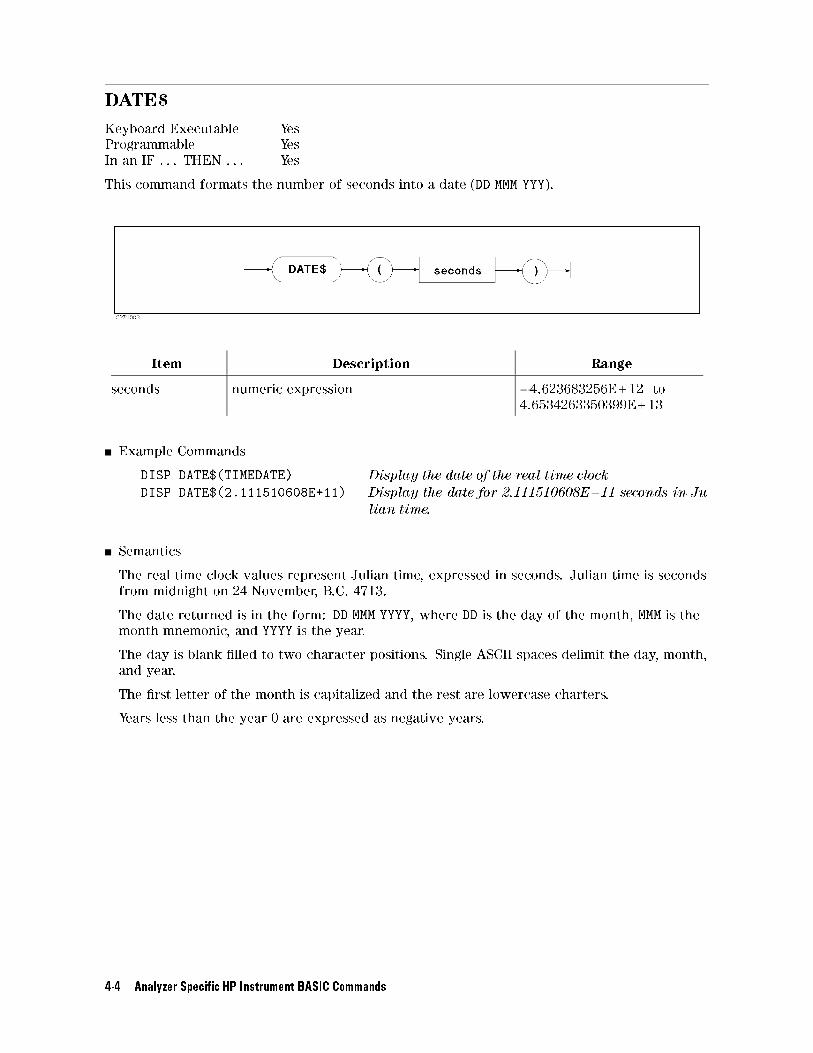
DATE$
Keyboard Executable Yes
Programmable Yes
In an IF . . . THEN . . . Yes
This command formats the number of seconds into a date (DD MMM YYY).
Item Description Range
seconds numeric expression �4.623683256E+12 to
4.6534263350399E+13
Example Commands
DISP DATE$(TIMEDATE) Display the date of the real time clock
DISP DATE$(2.111510608E+11) Display the date for 2.111510608E+11 seconds in Ju-
lian time.
Semantics
The real time clock values represent Julian time, expressed in seconds. Julian time is seconds
from midnight on 24 November, B.C. 4713.
The date returned is in the form: DD MMM YYYY, where DD is the day of the month, MMM is the
month mnemonic, and YYYY is the year.
The day is blank �lled to two character positions. Single ASCII spaces delimit the day, month,
and year.
The �rst letter of the month is capitalized and the rest are lowercase charters.
Years less than the year 0 are expressed as negative years.
4-4 Analyzer Speci�c HP Instrument BASIC Commands
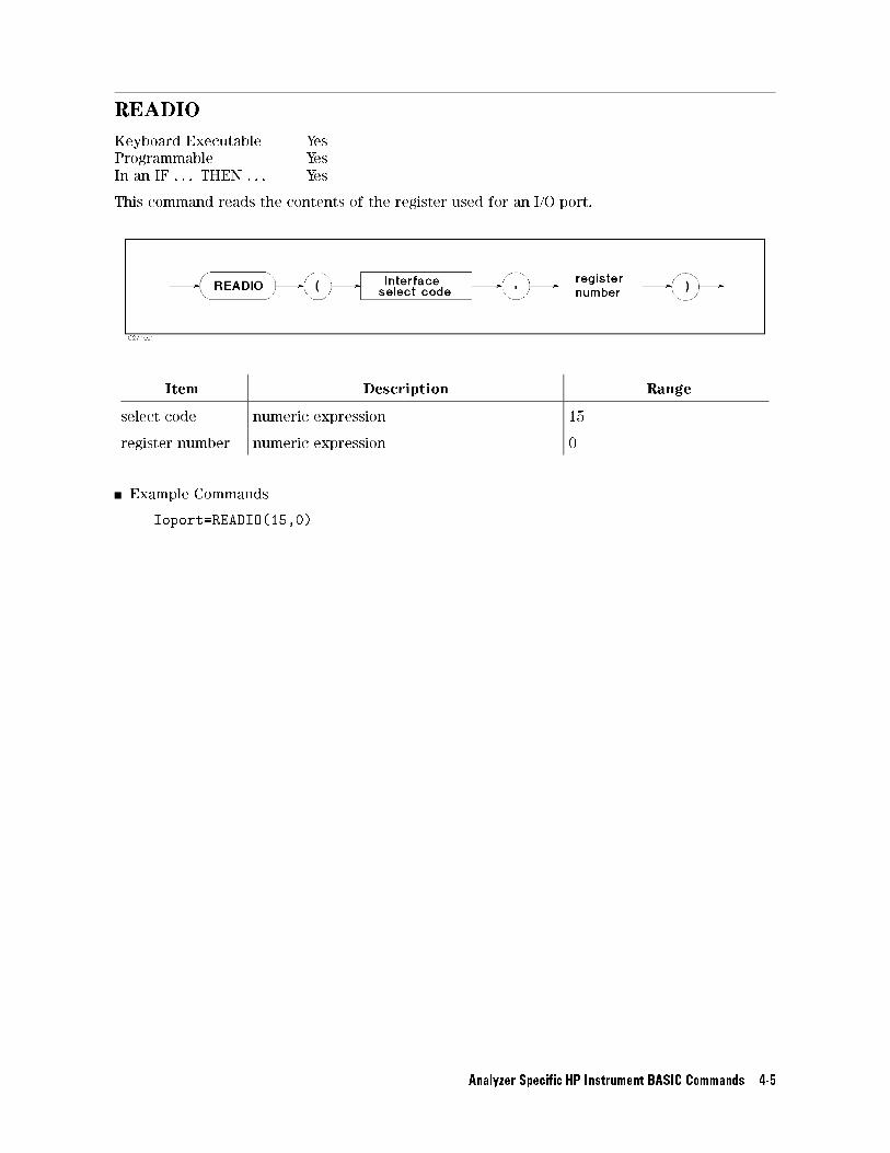
READIO
Keyboard Executable Yes
Programmable Yes
In an IF . . . THEN . . . Yes
This command reads the contents of the register used for an I/O port.
Item Description Range
select code numeric expression 15
register number numeric expression 0
Example Commands
Ioport=READIO(15,0)
Analyzer Speci�c HP Instrument BASIC Commands 4-5
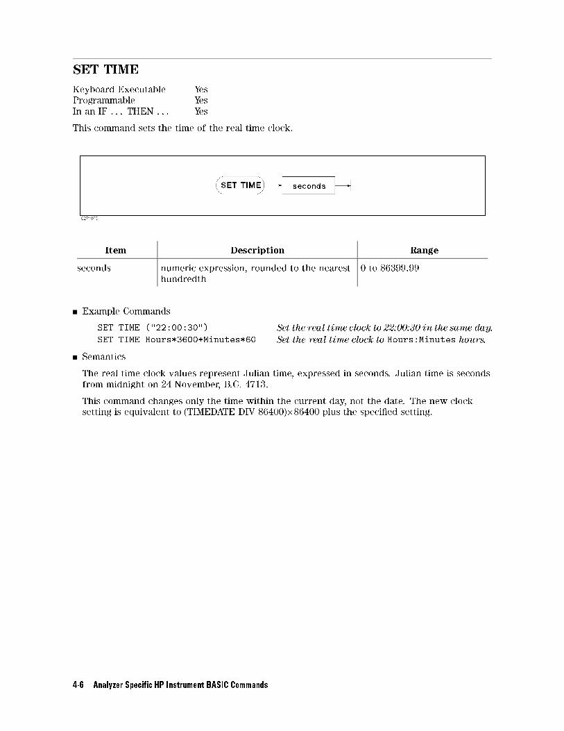
SET TIME
Keyboard Executable Yes
Programmable Yes
In an IF . . . THEN . . . Yes
This command sets the time of the real time clock.
Item Description Range
seconds numeric expression, rounded to the nearest
hundredth
0 to 86399.99
Example Commands
SET TIME ("22:00:30") Set the real time clock to 22:00:30 in the same day.
SET TIME Hours*3600+Minutes*60 Set the real time clock to Hours:Minutes hours.
Semantics
The real time clock values represent Julian time, expressed in seconds. Julian time is seconds
from midnight on 24 November, B.C. 4713.
This command changes only the time within the current day, not the date. The new clock
setting is equivalent to (TIMEDATE DIV 86400)�86400 plus the speci�ed setting.
4-6 Analyzer Speci�c HP Instrument BASIC Commands
SET TIMEDATE
Keyboard Executable Yes
Programmable Yes
In an IF . . . THEN . . . Yes
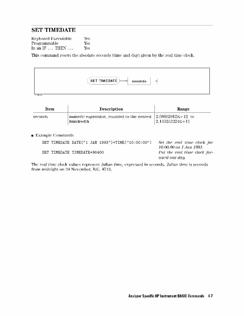
This command resets the absolute seconds (time and day) given by the real time clock.
Item Description Range
seconds numeric expression, rounded to the nearest
hundredth
2.08662912E+12 to
2.143252224E+11
Example Commands
SET TIMEDATE DATE("1 JAN 1993")+TIME("10:00:00") Set the real time clock for
10:00:00 on 1 Jan 1993.
SET TIMEDATE TIMEDATE+86400 Put the real time clock for-
ward one day.
The real time clock values represent Julian time, expressed in seconds. Julian time is seconds
from midnight on 24 November, B.C. 4713.
Analyzer Speci�c HP Instrument BASIC Commands 4-7
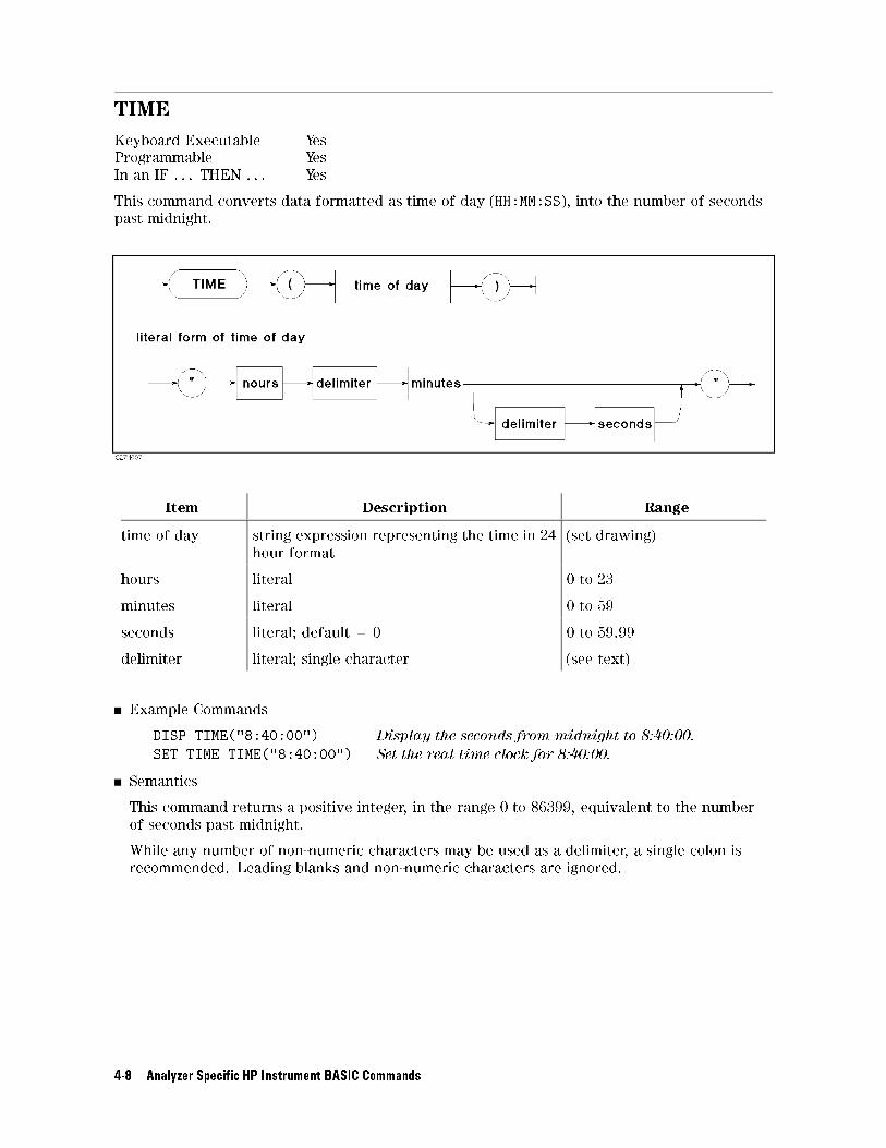
TIME
Keyboard Executable Yes
Programmable Yes
In an IF . . . THEN . . . Yes
This command converts data formatted as time of day (HH:MM:SS), into the number of seconds
past midnight.
Item Description Range
time of day string expression representing the time in 24
hour format
(set drawing)
hours literal 0 to 23
minutes literal 0 to 59
seconds literal; default = 0 0 to 59.99
delimiter literal; single character (see text)
Example Commands
DISP TIME("8:40:00") Display the seconds from midnight to 8:40:00.
SET TIME TIME("8:40:00") Set the real time clock for 8:40:00.
Semantics
This command returns a positive integer, in the range 0 to 86399, equivalent to the number
of seconds past midnight.
While any number of non-numeric characters may be used as a delimiter, a single colon is
recommended. Leading blanks and non-numeric characters are ignored.
4-8 Analyzer Speci�c HP Instrument BASIC Commands
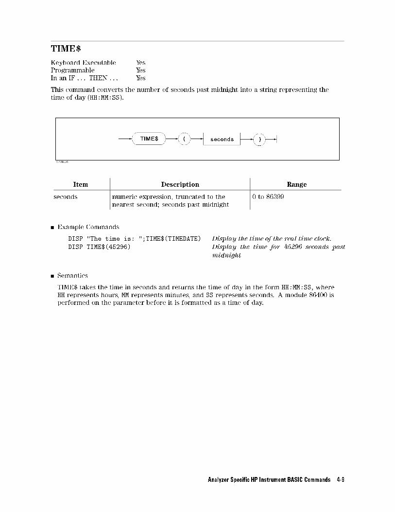
TIME$
Keyboard Executable Yes
Programmable Yes
In an IF . . . THEN . . . Yes
This command converts the number of seconds past midnight into a string representing the
time of day (HH:MM:SS).
Item Description Range
seconds numeric expression, truncated to the
nearest second; seconds past midnight
0 to 86399
Example Commands
DISP "The time is: ";TIME$(TIMEDATE) Display the time of the real time clock.
DISP TIME$(45296) Display the time for 45296 seconds past
midnight
Semantics
TIME$ takes the time in seconds and returns the time of day in the form HH:MM:SS, where
HH represents hours, MM represents minutes, and SS represents seconds. A module 86400 is
performed on the parameter before it is formatted as a time of day.
Analyzer Speci�c HP Instrument BASIC Commands 4-9
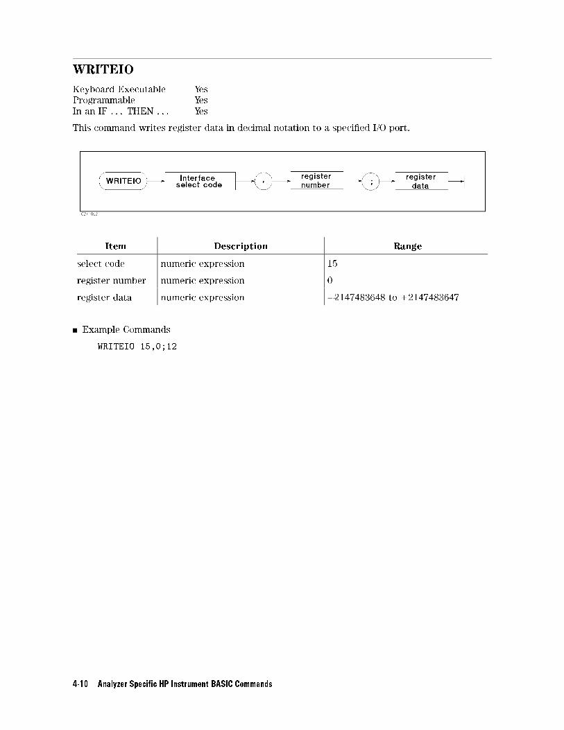
WRITEIO
Keyboard Executable Yes
Programmable Yes
In an IF . . . THEN . . . Yes
This command writes register data in decimal notation to a speci�ed I/O port.
Item Description Range
select code numeric expression 15
register number numeric expression 0
register data numeric expression �2147483648 to +2147483647
Example Commands
WRITEIO 15,0;12
4-10 Analyzer Speci�c HP Instrument BASIC Commands
A
Manual Changes
Introduction
This appendix contains the information required to adapt this manual to earlier versions or
con�gurations of the analyzer than the current printing date of this manual. The information
in this manual applies directly to the E5100A/B Network Analyzer serial number pre�x listed
on the title page of this manual.
Manual Changes
To adapt this manual to your E5100A/B, see Table A-1 and Table A-2, and make all the manual
changes listed opposite your instrument's serial number and �rmware version.
Instruments manufactured after the printing of this manual may be di�erent from those
documented in this manual. Later instrument versions will be documented in a manual
changes supplement that will accompany the manual shipped with that instrument. If your
instrument's serial number is not listed on the title page of this manual or in Table A-1, it may
be documented in a yellow MANUAL CHANGES supplement.
In additions to change information, the supplement may contain information for correcting
errors (Errata) in the manual. To keep this manual as current and accurate as possible,
Agilent Technologies recommends that you periodically request the latest MANUAL CHANGES
supplement.
For information concerning serial number pre�xes not listed on the title page or in the
MANUAL CHANGES supplement, contact the nearest Agilent Technologies o�ce.
Turn on the line switch or execute the *IDN? command by GPIB to con�rm the �rmware
version. See the GPIB Command Reference manual for information on the *IDN? command.
Table A-1. Manual Changes by Serial Number
Serial Pre�x or Number Make Manual Changes
Table A-2. Manual Changes by Firmware Version
Version Make Manual Changes
Manual Changes A-1
Instruments Covered by This Manual
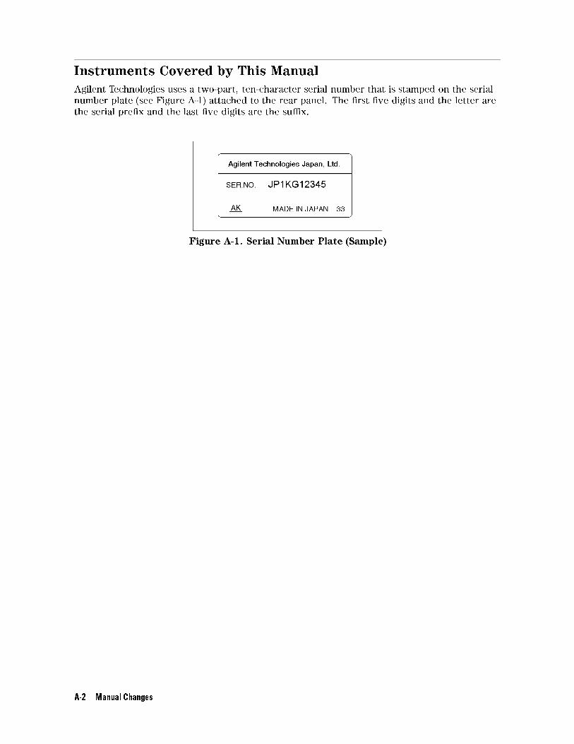
Agilent Technologies uses a two-part, ten-character serial number that is stamped on the serial
number plate (see Figure A-1) attached to the rear panel. The �rst �ve digits and the letter are
the serial pre�x and the last �ve digits are the su�x.
Figure A-1. Serial Number Plate (Sample)
A-2 Manual Changes
B
Keyboard
The keyboard keys are arranged into the following functional groups:
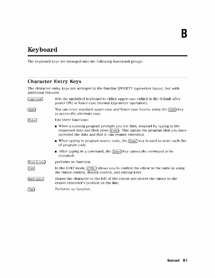
Character Entry Keys
The character entry keys are arranged in the familiar QWERTY typewriter layout, but with
additional features.
�Caps Lock� Sets the unshifted keyboard to either upper-case (which is the default after
power ON) or lower-case (normal typewriter operation).
�Shift� You can enter standard upper-case and lower-case letters, using the �Shift� keyto access the alternate case.
�Enter� Has three functions:
When a running program prompts you for data, respond by typing in the
requested data and then press �Enter�. This signals the program that you have
provided the data and that it can resume execution.
When typing in program source code, the �Enter� key is used to store each line
of program code.
After typing in a command, the �Enter� key causes the command to be
executed.
�Print Screen� performs no function.
�Ctrl� In the EDIT mode, �CTRL� allows you to control the editor in the same as using
the cursor-control, display-control, and editing keys.
�Back space� Erases the character to the left of the cursor and moves the cursor to the
erased character's position on the line.
�Tab� Performs no function.
Keyboard B-1
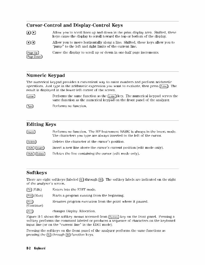
Cursor-Control and Display-Control Keys
��� �� Allow you to scroll lines up and down in the print display area. Shifted, these
keys cause the display to scroll toward the top or bottom of the display.
��� ��� Allow you to move horizontally along a line. Shifted, these keys allow you to
\jump" to the left and right limits of the current line.
�Page Up��Page Down�
Cause the display to scroll up or down in one-half page increments.
Numeric Keypad
The numerical keypad provides a convenient way to enter numbers and perform arithmetic
operations. Just type in the arithmetic expression you want to evaluate, then press �Enter�. Theresult is displayed in the lower-left corner of the screen.
�Enter� Performs the same function as the �Enter� key. The numerical keypad serves the
same function as the numerical keypad on the front panel of the analyzer.
�Tab� Performs no function.
Editing Keys
�Insert� Performs no function. The HP Instrument BASIC is always in the insert mode.
The characters you type are always inserted to the left of the cursor.
�Delete� Deletes the character at the cursor's position.
�Shift� �Insert� Insert a new line above the cursor's current position (edit mode only).
�Shift� �Delete� Deletes the line containing the cursor (edit mode only).
Softkeys
There are eight softkeys (labeled �f1� through �f8�. The softkey labels are indicated on the right
of the analyzer's screen.
�F9� (Edit) Enters into the EDIT mode.
�F10� (Run) Starts a program running from the beginning.
�F11�(Continue)
Resumes program execution from the point where it paused.
�F12� changes Display Allocation.
Figure B-1 shows the softkey menus accessed from �System� key on the front panel. Pressing a
softkey performs the command labeled or produces a sequence of characters on the keyboard
input line (or on the \current line" in the EDIT mode).
Pressing the softkeys on the front panel of the analyzer performs the same functions as
pressing the �f1� through �f8� function keys.
B-2 Keyboard
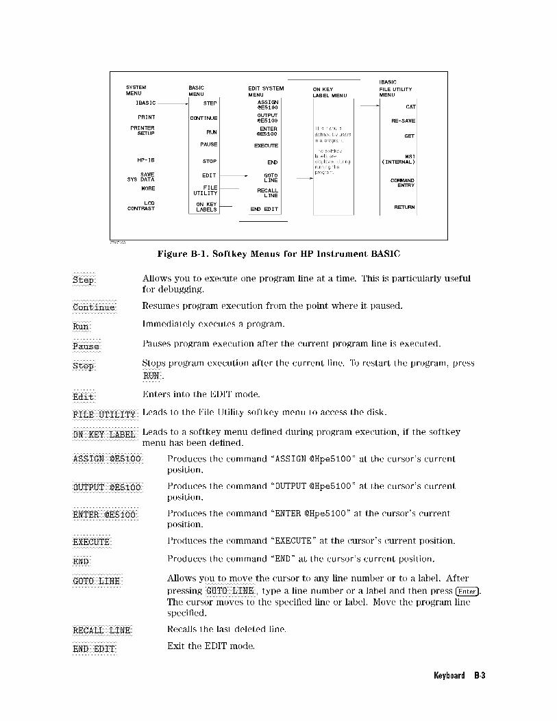
Figure B-1. Softkey Menus for HP Instrument BASIC
NNNNNNNNNNNNNNStep Allows you to execute one program line at a time. This is particularly useful
for debugging.NNNNNNNNNNNNNNNNNNNNNNNNNNContinue Resumes program execution from the point where it paused.
NNNNNNNNNNNRun Immediately executes a program.
NNNNNNNNNNNNNNNNNPause Pauses program execution after the current program line is executed.
NNNNNNNNNNNNNNStop Stops program execution after the current line. To restart the program, pressNNNNNNNNNNN
RUN .
NNNNNNNNNNNNNNEdit Enters into the EDIT mode.
NNNNNNNNNNNNNNNNNNNNNNNNNNNNNNNNNNNNNNFILE UTILITY Leads to the File Utility softkey menu to access the disk.
NNNNNNNNNNNNNNNNNNNNNNNNNNNNNNNNNNNNNNON KEY LABEL Leads to a softkey menu de�ned during program execution, if the softkey
menu has been de�ned.NNNNNNNNNNNNNNNNNNNNNNNNNNNNNNNNNNNNNNNNNASSIGN @E5100 Produces the command \ASSIGN @Hpe5100" at the cursor's current
position.NNNNNNNNNNNNNNNNNNNNNNNNNNNNNNNNNNNNNNNNNOUTPUT @E5100 Produces the command \OUTPUT @Hpe5100" at the cursor's current
position.NNNNNNNNNNNNNNNNNNNNNNNNNNNNNNNNNNNNNNENTER @E5100 Produces the command \ENTER @Hpe5100" at the cursor's current
position.NNNNNNNNNNNNNNNNNNNNNNNEXECUTE Produces the command \EXECUTE" at the cursor's current position.
NNNNNNNNNNNEND Produces the command \END" at the cursor's current position.
NNNNNNNNNNNNNNNNNNNNNNNNNNNNNGOTO LINE Allows you to move the cursor to any line number or to a label. After
pressingNNNNNNNNNNNNNNNNNNNNNNNNNNNNNGOTO LINE , type a line number or a label and then press �Enter�.
The cursor moves to the speci�ed line or label. Move the program line
speci�ed.NNNNNNNNNNNNNNNNNNNNNNNNNNNNNNNNNNNRECALL LINE Recalls the last deleted line.
NNNNNNNNNNNNNNNNNNNNNNNNNNEND EDIT Exit the EDIT mode.
Keyboard B-3

NNNNNNNNNNNCAT Produces the command \CAT". CAT lists the contents of a mass storage
directory.NNNNNNNNNNNNNNNNNNNNNNNRE-SAVE Produces the command \RE-SAVE""". RE-SAVE creates a speci�ed ASCII �le
if it does not exist; otherwise, it rewrites a speci�ed ASCII �le by copying
program lines as strings into that �le.NNNNNNNNNNNGET Produces the command \GET""". GET reads the speci�ed ASCII �le and
attempts to store the strings into memory as program lines.NNNNNNNNNNNNNNNNNNNNNNNMSI [ ] Change the mass storage devise.
B-4 Keyboard
Index
A
arrow key
��, B-2���, B-2���, B-2���, B-2
AUTOST , 3-1
auto start program , 3-1
B
�Backspace�, B-1built-in disk drive , 3-3
C
�Caps Lock�, B-1character entry key, B-1
�Ctrl�, B-1
D
DATE, 4-2
DATE$, 4-4
�Delete�, B-2disk drive , 3-3
display allocation , 3-1
E
�Enter�, B-1, B-2external RUN/CONT connector, 3-5
trigger signal , 3-5
G
graphics, 3-4
H
HP Instrument BASIC, 1-1
I
IBASIC, 1-1
initialize
storage , 3-3
�Insert�, B-2I/O interfaces, 3-5
K
keyboard, B-1
Keyboard
connection , 2-1
M
manual changes, A-1
mass storage , 3-3
O
OFF CYCLE, 4-1
ON CYCLE, 4-1
P
�Page Down�, B-2�Page Up�, B-2�Print Screen�, B-1program
editing , 2-2
listing , 2-3
loading , 2-4
saving , 2-3
R
ram disk memory , 3-3
READIO, 4-5
RUN/CONT connector, 3-5
trigger signal , 3-5
run light indication , 3-2
S
select code, 3-5
serial number, A-2
SET TIME, 4-6
SET TIMEDATE, 4-7
�Shift�, B-1storage
format , 3-3
initialize , 3-3
unit , 3-3
T
�Tab�, B-1, B-2TIME, 4-8
TIME$, 4-9
W
WRITEIO, 4-10
Index-1


REGIONAL SALES AND SUPPORT OFFICESFor more information about Agilent Technologies test and measurement products, applications, services, andfor a current sales office listing, visit our web site: http://www.agilent.com/find/tmdir. You can also contact oneof the following centers and ask for a test and measurement sales representative. 11/29/99
United States:Agilent TechnologiesTest and Measurement Call CenterP.O.Box 4026Englewood, CO 80155-4026(tel) 1 800 452 4844
Canada:Agilent Technologies Canada Inc.5150 Spectrum WayMississauga, OntarioL4W 5G1(tel) 1 877 894 4414
Europe:Agilent TechnologiesTest & MeasurementEuropean Marketing OrganizationP.O.Box 9991180 AZ AmstelveenThe Netherlands(tel) (31 20) 547 9999
Japan:Agilent Technologies Japan Ltd.Call Center9-1, Takakura-Cho, Hachioji-Shi,Tokyo 192-8510, Japan(tel) (81) 426 56 7832(fax) (81) 426 56 7840
Latin America:Agilent TechnologiesLatin American Region Headquarters5200 Blue Lagoon Drive, Suite #950Miami, Florida 33126U.S.A.(tel) (305) 267 4245(fax) (305) 267 4286
Australia/New Zealand:Agilent Technologies Australia Pty Ltd347 Burwood HighwayForest Hill, Victoria 3131(tel) 1-800 629 485 (Australia)
(fax) (61 3) 9272 0749(tel) 0 800 738 378 (New Zealand)(fax) (64 4) 802 6881
Asia Pacific:Agilent Technologies24/F, Cityplaza One, 1111 King’s Road,Taikoo Shing, Hong Kong(tel) (852)-3197-7777(fax) (852)-2506-9284