Embed Size (px)
Citation preview
Protocol Manual - F/W Vr. 2.0.0 1
Serial communication protocol ModBUS® for KX6 controllers
2 Protocol Manual - F/W Vr. 2.0.0
KX6 Communication Protocol Ascon Tecnologic S.r.l.
KX6 ControllerS CoMMUniCation protoCol
inDeX
1 preface ............................................................................. 3
2 physical connection ...................................................... 32.1 Interface ................................................................................................................. 3
2.2 Line ........................................................................................................................ 3
3 Communication protocol ............................................... 43.1 Function code 3: read multiple registers (maximum 16 registers) ......................... 4
3.2 Function code 6: write a single word (one location)............................................... 5
3.3 Function code 16: preset multiple registers (maximum 16 registers) .................... 6
3.4 The exception reply ............................................................................................... 7
3.5 Cyclic redundancy check (CRC) ............................................................................ 8
4 Data exchange ................................................................. 104.1 Some definitions .................................................................................................... 10
4.2 Memory zones ....................................................................................................... 10
4.3 Variables zones ..................................................................................................... 10
4.4 Most important changes ........................................................................................ 10
Protocol Manual - F/W Vr. 2.0.0 3
Ascon Tecnologic S.r.l. KX6 Communication Protocol
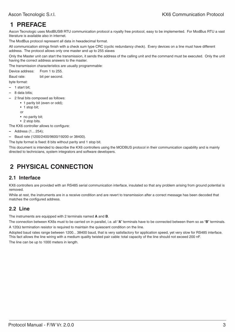
1 prefaCeAscon Tecnologic uses ModBUS® RTU communication protocol a royalty free protocol, easy to be implemented. For ModBus RTU a vast literature is available also in internet.
The ModBus protocol represent all data in hexadecimal format.
All communication strings finish with a check sum type CRC (cyclic redundancy check). Every devices on a line must have different address. The protocol allows only one master and up to 255 slaves
Only the Master unit can start the transmission, it sends the address of the calling unit and the command must be executed. Only the unit having the correct address answers to the master.
The transmission characteristics are usually programmable:
Device address: From 1 to 255.
Baud rate: bit per second.
byte format:
– 1 start bit;
– 8 data bitis;
– 2 final bits composed as follows:• 1 parity bit (even or odd);• 1 stop bit;or• no parity bit;• 2 stop bits.
The KX6 controller allows to configure:
– Address (1... 254);
– Baud rate (1200/2400/9600/19200 or 38400).
The byte format is fixed: 8 bits without parity and 1 stop bit.
This document is intended to describe the KX6 controllers using the MODBUS protocol in their communication capability and is mainly directed to technicians, system integrators and software developers.
2 phySiCal ConneCtion
2.1 interfaceKX6 controllers are provided with an RS485 serial communication interface, insulated so that any problem arising from ground potential is removed.
While at rest, the instruments are in a receive condition and are revert to transmission after a correct message has been decoded that matches the configured address.
2.2 lineThe instruments are equipped with 2 terminals named a and B.
The connection between KX6s must to be carried on in parallel, i.e. all “a” terminals have to be connected between them so as “B” terminals.
A 120W termination resistor is required to maintain the quiescent condition on the line.
Adopted baud rates range between 1200... 38400 baud, that is very satisfactory for application speed, yet very slow for RS485 interface. This fact allows the line wiring with a medium quality twisted pair cable: total capacity of the line should not exceed 200 nF.
The line can be up to 1000 meters in length.
4 Protocol Manual - F/W Vr. 2.0.0
KX6 Communication Protocol Ascon Tecnologic S.r.l.
3 CoMMUniCation protoColThe protocol adopted by KX6 is a subset of the widely used MODBUS RTU (JBUS, AEG Schneider Automation, Inc. registered trademark) protocol, so that connections are easy for many commercial PLCs and supervisory programs.
For users needing to develop their own communication software, all information is available as well as implementation hints.
The MODBUS RTU (JBUS) communication functions implemented in KX6 Kube serie are:Function 3 Read n register;Function 6 Preset one register;Function 16 Preset multiple registers.These functions allow the supervisory program to read and modify any data of the controller. The communication is based on messages sent by the master station (host) to the slave stations and viceversa. The slave station that recognises the message as sent to it, analyses the content and, if it is formally and semantically correct, generates a reply message directed back to the master.
The communication process involves five types of messages:
from master to slave from slave to master
Function 3: read n registers request Function 3: read n registers reply
Function 6: preset one register request Function 6: preset one register reply
Function 16: preset multiple registers request Function 16: preset multiple registers reply
Exception reply (as reply to all functions in abnormal conditions)
All messages contain four fields:
◊ Slave address (from 1 to 255): MODBUS RTU (JBUS) reserves address 0 for broadcasting messages and it is implemented in the KX6 series;
◊ Function code: contains 3, 6 or 16 for specified functions;
◊ Information field: contains data like word addresses and word values as required by function in use;
◊ Control word: a cyclic redundancy check (CRC) performed with particular rules for CRC16.
The characteristics of the asyncronous transmission are 8 bits, no parity, one stop bit.
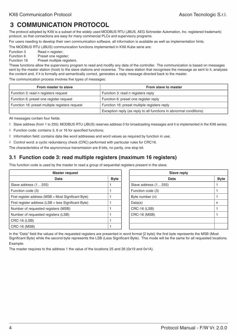
3.1 function code 3: read multiple registers (maximum 16 registers)This function code is used by the master to read a group of sequential registers present in the slave.
Master request Slave reply
Data Byte Data Byte
Slave address (1... 255) 1 Slave address (1... 255) 1
Function code (3) 1 Function code (3) 1
First register address (MSB = Most Significant Byte) 1 Byte number (n) 1
First register address (LSB = less Significant Byte) 1 Data(s) n
Number of requested registers (MSB) 1 CRC-16 (LSB) 1
Number of requested registers (LSB) 1 CRC-16 (MSB) 1
CRC-16 (LSB) 1
CRC-16 (MSB) 1
In the “Data” field the values of the requested registers are presented in word format [2 byte]: the first byte represents the MSB (Most Significant Byte) while the second byte represents the LSB (Less Significant Byte). This mode will be the same for all requested locations.
Example:
The master requires to the address 1 the value of the locations 25 and 26 (0x19 and 0x1A).
Protocol Manual - F/W Vr. 2.0.0 5
Ascon Tecnologic S.r.l. KX6 Communication Protocol
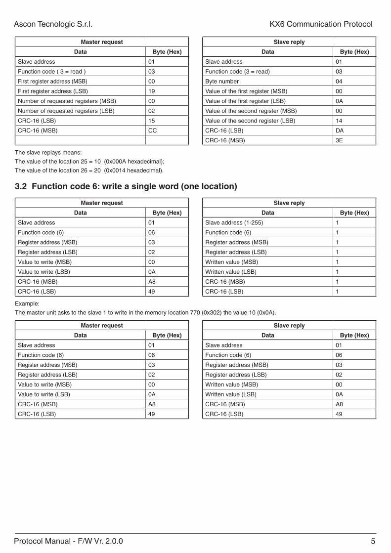
Master request Slave reply
Data Byte (hex) Data Byte (hex)
Slave address 01 Slave address 01
Function code ( 3 = read ) 03 Function code (3 = read) 03
First register address (MSB) 00 Byte number 04
First register address (LSB) 19 Value of the first register (MSB) 00
Number of requested registers (MSB) 00 Value of the first register (LSB) 0A
Number of requested registers (LSB) 02 Value of the second register (MSB) 00
CRC-16 (LSB) 15 Value of the second register (LSB) 14
CRC-16 (MSB) CC CRC-16 (LSB) DA
CRC-16 (MSB) 3E
The slave replays means:
The value of the location 25 = 10 (0x000A hexadecimal);
The value of the location 26 = 20 (0x0014 hexadecimal).
3.2 function code 6: write a single word (one location)
Master request Slave reply
Data Byte (hex) Data Byte (hex)
Slave address 01 Slave address (1-255) 1
Function code (6) 06 Function code (6) 1
Register address (MSB) 03 Register address (MSB) 1
Register address (LSB) 02 Register address (LSB) 1
Value to write (MSB) 00 Written value (MSB) 1
Value to write (LSB) 0A Written value (LSB) 1
CRC-16 (MSB) A8 CRC-16 (MSB) 1
CRC-16 (LSB) 49 CRC-16 (LSB) 1
Example:
The master unit asks to the slave 1 to write in the memory location 770 (0x302) the value 10 (0x0A).
Master request Slave reply
Data Byte (hex) Data Byte (hex)
Slave address 01 Slave address 01
Function code (6) 06 Function code (6) 06
Register address (MSB) 03 Register address (MSB) 03
Register address (LSB) 02 Register address (LSB) 02
Value to write (MSB) 00 Written value (MSB) 00
Value to write (LSB) 0A Written value (LSB) 0A
CRC-16 (MSB) A8 CRC-16 (MSB) A8
CRC-16 (LSB) 49 CRC-16 (LSB) 49
6 Protocol Manual - F/W Vr. 2.0.0
KX6 Communication Protocol Ascon Tecnologic S.r.l.
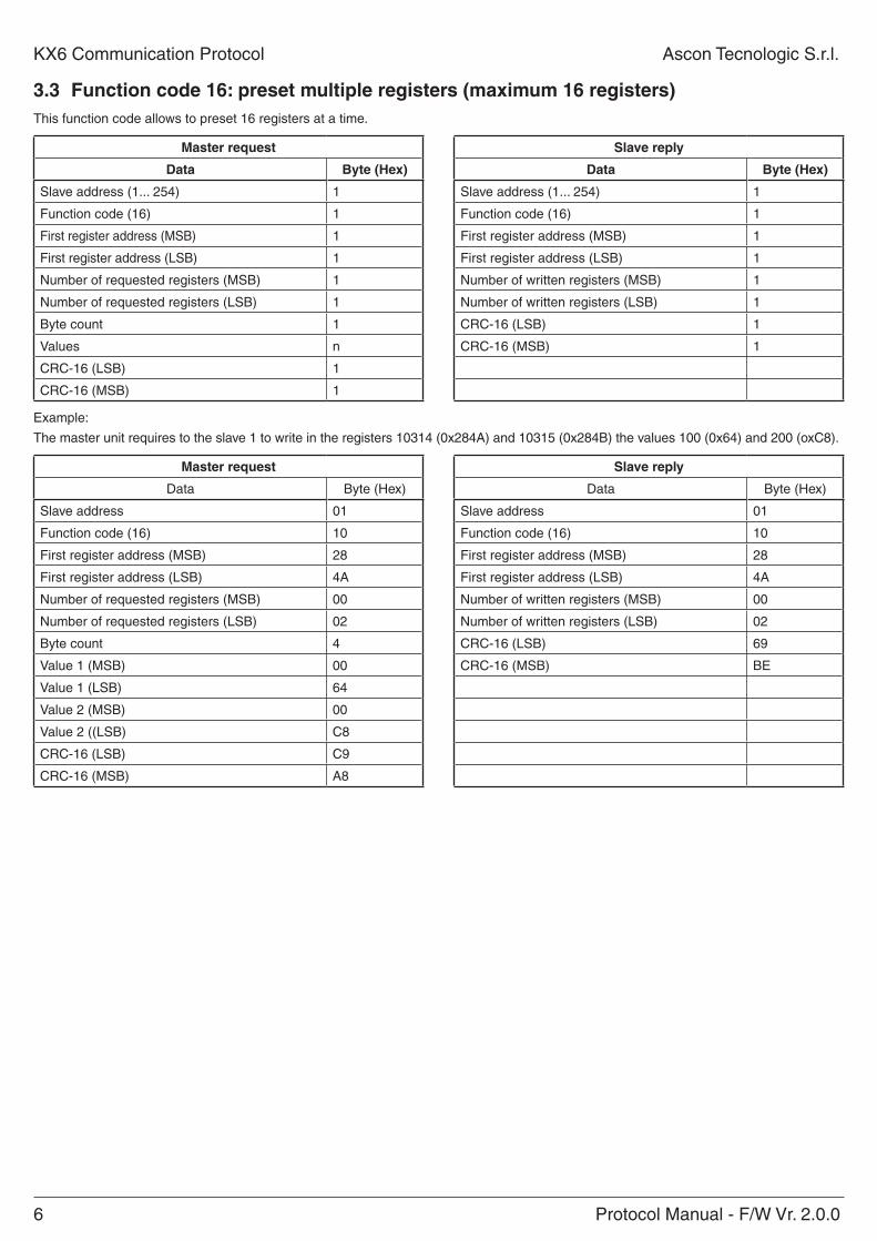
3.3 function code 16: preset multiple registers (maximum 16 registers)This function code allows to preset 16 registers at a time.
Master request Slave reply
Data Byte (hex) Data Byte (hex)
Slave address (1... 254) 1 Slave address (1... 254) 1
Function code (16) 1 Function code (16) 1
First register address (MSB) 1 First register address (MSB) 1
First register address (LSB) 1 First register address (LSB) 1
Number of requested registers (MSB) 1 Number of written registers (MSB) 1
Number of requested registers (LSB) 1 Number of written registers (LSB) 1
Byte count 1 CRC-16 (LSB) 1
Values n CRC-16 (MSB) 1
CRC-16 (LSB) 1
CRC-16 (MSB) 1
Example:
The master unit requires to the slave 1 to write in the registers 10314 (0x284A) and 10315 (0x284B) the values 100 (0x64) and 200 (oxC8).
Master request Slave reply
Data Byte (Hex) Data Byte (Hex)
Slave address 01 Slave address 01
Function code (16) 10 Function code (16) 10
First register address (MSB) 28 First register address (MSB) 28
First register address (LSB) 4A First register address (LSB) 4A
Number of requested registers (MSB) 00 Number of written registers (MSB) 00
Number of requested registers (LSB) 02 Number of written registers (LSB) 02
Byte count 4 CRC-16 (LSB) 69
Value 1 (MSB) 00 CRC-16 (MSB) BE
Value 1 (LSB) 64
Value 2 (MSB) 00
Value 2 ((LSB) C8
CRC-16 (LSB) C9
CRC-16 (MSB) A8
Protocol Manual - F/W Vr. 2.0.0 7
Ascon Tecnologic S.r.l. KX6 Communication Protocol
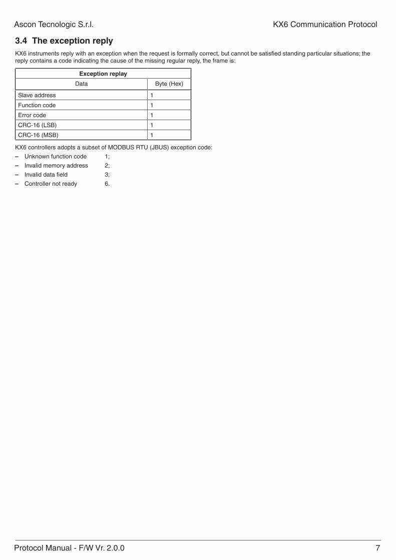
3.4 the exception replyKX6 instruments reply with an exception when the request is formally correct, but cannot be satisfied standing particular situations; the reply contains a code indicating the cause of the missing regular reply, the frame is:
exception replay
Data Byte (Hex)
Slave address 1
Function code 1
Error code 1
CRC-16 (LSB) 1
CRC-16 (MSB) 1
KX6 controllers adopts a subset of MODBUS RTU (JBUS) exception code:
– Unknown function code 1;
– Invalid memory address 2;
– Invalid data field 3;
– Controller not ready 6.
8 Protocol Manual - F/W Vr. 2.0.0
KX6 Communication Protocol Ascon Tecnologic S.r.l.
3.5 Cyclic redundancy check (CrC)CRC is a check word that permits to verify the integrity of a message. Every message, sent or received, has in the two last characters the CRC check word.
After receiving a request, the controller checks the validity of the received message comparing the received CRC with the calculated one.
When a reply is ready the controller calculates the CRC word and adds two characters to the prepared message.
CRC calculation is performed on every character of the message, excluding the last two.
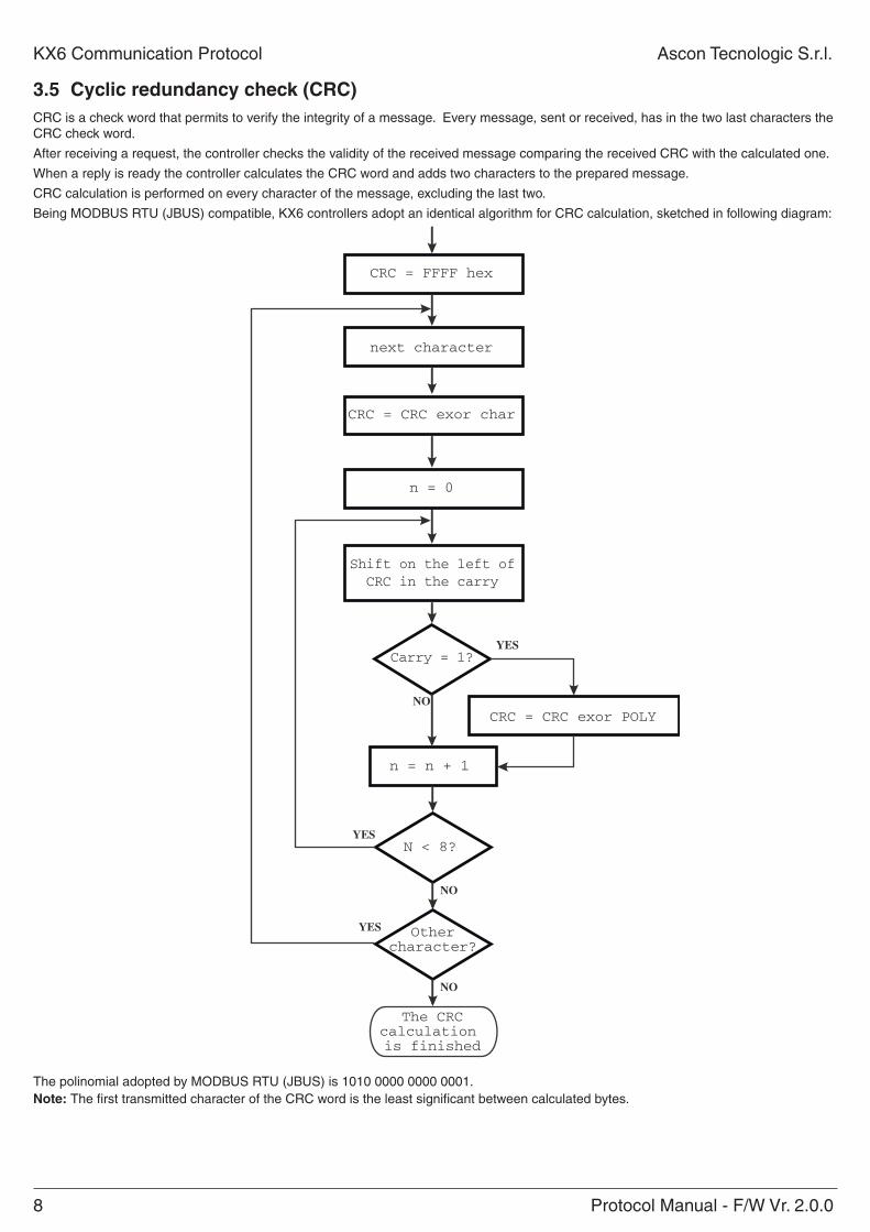
Being MODBUS RTU (JBUS) compatible, KX6 controllers adopt an identical algorithm for CRC calculation, sketched in following diagram:
CRC = CRC exor char
Shift on the left ofCRC in the carry
NO
YES
n = n + 1
NO
YESN < 8?
YES
The CRCcalculation is finished
CRC = FFFF hex
next character
CRC = CRC exor POLY
Carry = 1?
Othercharacter?
n = 0
NO
The polinomial adopted by MODBUS RTU (JBUS) is 1010 0000 0000 0001.note: The first transmitted character of the CRC word is the least significant between calculated bytes.
Protocol Manual - F/W Vr. 2.0.0 9
Ascon Tecnologic S.r.l. KX6 Communication Protocol
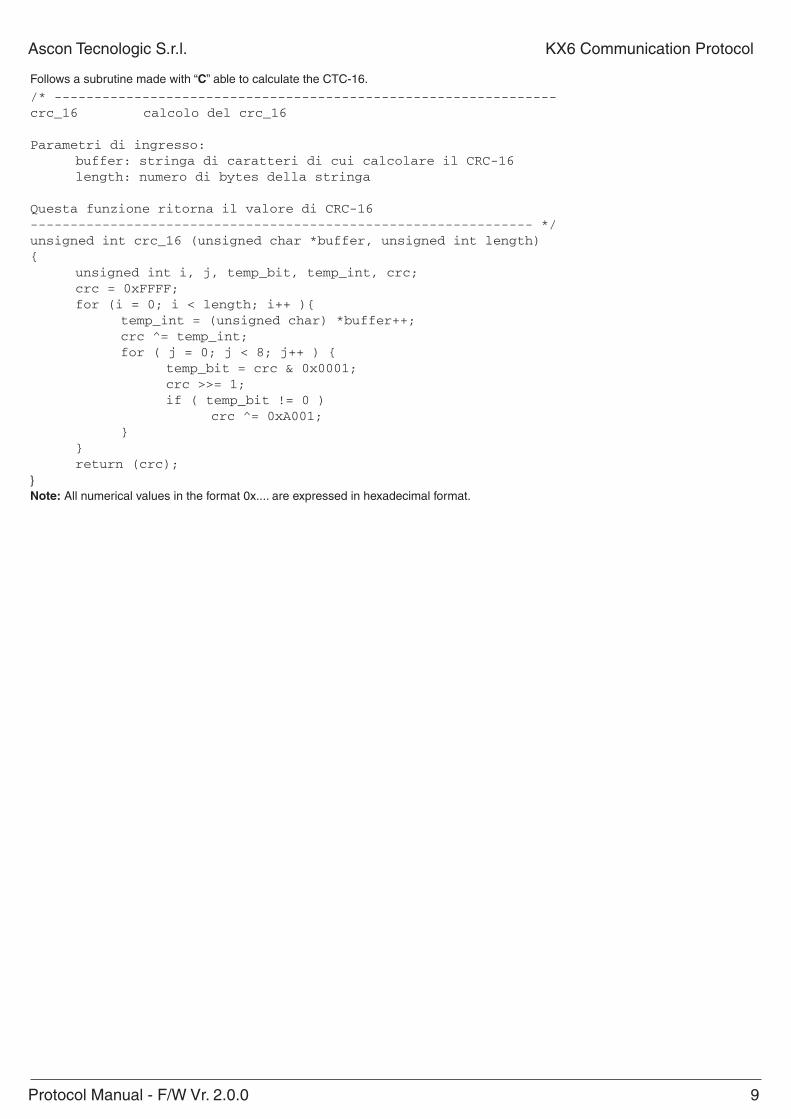
Follows a subrutine made with “C” able to calculate the CTC-16.
/* ---------------------------------------------------------------crc_16 calcolo del crc_16
Parametri di ingresso: buffer: stringa di caratteri di cui calcolare il CRC-16 length: numero di bytes della stringa
Questa funzione ritorna il valore di CRC-16--------------------------------------------------------------- */unsigned int crc_16 (unsigned char *buffer, unsigned int length){ unsigned int i, j, temp_bit, temp_int, crc; crc = 0xFFFF; for (i = 0; i < length; i++ ){ temp_int = (unsigned char) *buffer++; crc ^= temp_int; for ( j = 0; j < 8; j++ ) { temp_bit = crc & 0x0001; crc >>= 1; if ( temp_bit != 0 ) crc ^= 0xA001; } } return (crc);}note: All numerical values in the format 0x.... are expressed in hexadecimal format.
10 Protocol Manual - F/W Vr. 2.0.0
KX6 Communication Protocol Ascon Tecnologic S.r.l.
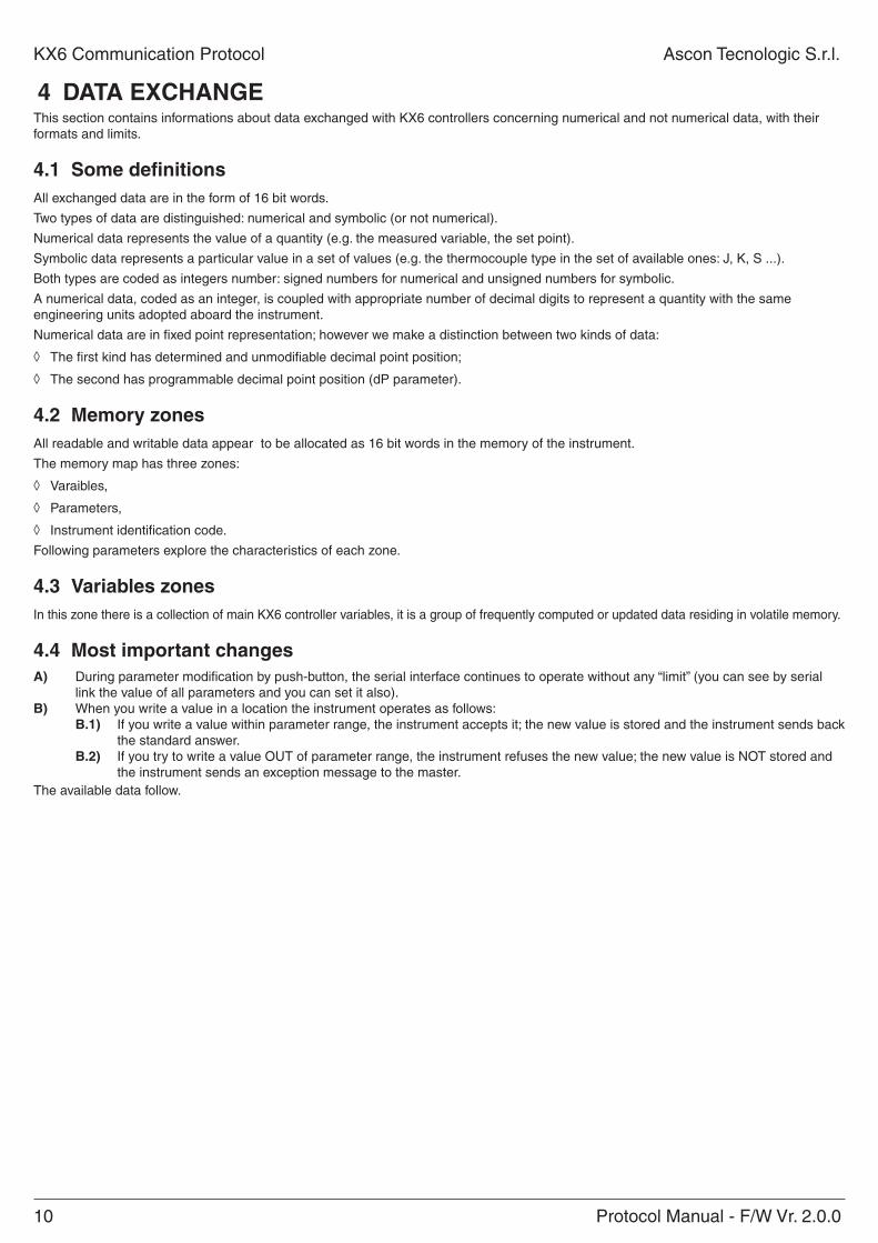
4 Data eXChangeThis section contains informations about data exchanged with KX6 controllers concerning numerical and not numerical data, with their formats and limits.
4.1 Some definitionsAll exchanged data are in the form of 16 bit words.
Two types of data are distinguished: numerical and symbolic (or not numerical).
Numerical data represents the value of a quantity (e.g. the measured variable, the set point).
Symbolic data represents a particular value in a set of values (e.g. the thermocouple type in the set of available ones: J, K, S ...).
Both types are coded as integers number: signed numbers for numerical and unsigned numbers for symbolic.
A numerical data, coded as an integer, is coupled with appropriate number of decimal digits to represent a quantity with the same engineering units adopted aboard the instrument.
Numerical data are in fixed point representation; however we make a distinction between two kinds of data:
◊ The first kind has determined and unmodifiable decimal point position;
◊ The second has programmable decimal point position (dP parameter).
4.2 Memory zonesAll readable and writable data appear to be allocated as 16 bit words in the memory of the instrument.
The memory map has three zones:
◊ Varaibles,
◊ Parameters,
◊ Instrument identification code.
Following parameters explore the characteristics of each zone.
4.3 Variables zonesIn this zone there is a collection of main KX6 controller variables, it is a group of frequently computed or updated data residing in volatile memory.
4.4 Most important changesa) During parameter modification by push-button, the serial interface continues to operate without any “limit” (you can see by serial
link the value of all parameters and you can set it also).B) When you write a value in a location the instrument operates as follows:
B.1) If you write a value within parameter range, the instrument accepts it; the new value is stored and the instrument sends back the standard answer.
B.2) If you try to write a value OUT of parameter range, the instrument refuses the new value; the new value is NOT stored and the instrument sends an exception message to the master.
The available data follow.
Protocol Manual - F/W Vr. 2.0.0 11
Ascon Tecnologic S.r.l. KX6 Communication Protocol
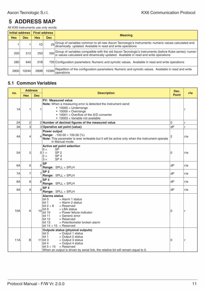
5 aDDreSS MapAll KX6 instruments use only words:
initial address final addressMeaning
hex Dec hex Dec
1 1 1D 29 Group of variables common to all new Ascon Tecnologic’s instruments: numeric values calculated and dinamically updated. Available in read and write operations
200 512 250 592 Group of variables compatible with the old Ascon Tecnologic’s instruments (before Kube series): numer-ic values calculated and dinamically updated. Available in read and write operations
280 640 31B 795 Configuration parameters: Numeric and symolic values. Available in read and write operations
2800 10240 289B 10395 Repetition of the configuration parameters: Numeric and symolic values. Available in read and write operations
5.1 Common Variables
no.address
DescriptionDec. point
r/whex Dec
1A 1 1
pV: Measured valuenote: When a measuring error is detected the instrument send:
• 10000 = Underrange• 10000 = Overrange• 10001 = Overflow of the A/D converter• 10003 = Variable not available
r
2A 2 2 number of decimal figures of the measured value 0 r3A 3 3 operative set point (value) dP r
4A 4 4
power output range: -100.00 ÷ 100.00 (%)note: This parameter is ever writeable but it will be active only when the instrument operate
in Manual mode.
2 r/w
5A 5 5
active set point selection0 = SP1 = SP 22 = SP 33 = SP 4
0 r/w
6A 6 6Sprange: SPLL ÷ SPLH
dP r/w
7A 7 7Sp 2range: SPLL ÷ SPLH
dP r/w
8A 8 8Sp 3range: SPLL ÷ SPLH
dP r/w
9A 9 9Sp 4range: SPLL ÷ SPLH
dP r/w
10A A 10
alarms statusbit 0 = Alarm 1 statusbit 1 = Alarm 2 statusbit 2 ÷ 8 = Reservedbit 9 = LBA statusbit 10 = Power feilure indicatorbit 11 = Generic errorbit 12 = Reservedbit 13 = Potentiometer broken alarmbit 14 ÷ 15 = Reserved
0 r
11A B 11
outputs status (physical outputs) bit 0 = Output 1 statusbit 1 = Output 2 statusbit 3 = Output 3 statusbit 4 = Output 4 statusbit 5 ÷ 15 = ReservedWhen an output is driven by serial link, the relative bit will remain equal to 0.
0 r
12 Protocol Manual - F/W Vr. 2.0.0
KX6 Communication Protocol Ascon Tecnologic S.r.l.
no.address
DescriptionDec. point
r/whex Dec
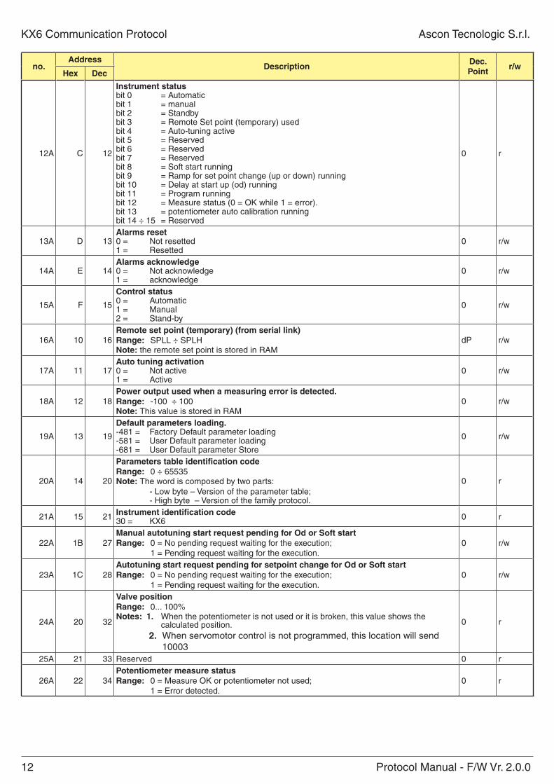
12A C 12
instrument statusbit 0 = Automaticbit 1 = manualbit 2 = Standbybit 3 = Remote Set point (temporary) usedbit 4 = Auto-tuning activebit 5 = Reservedbit 6 = Reservedbit 7 = Reservedbit 8 = Soft start runningbit 9 = Ramp for set point change (up or down) runningbit 10 = Delay at start up (od) runningbit 11 = Program runningbit 12 = Measure status (0 = OK while 1 = error).bit 13 = potentiometer auto calibration runningbit 14 ÷ 15 = Reserved
0 r
13A D 13alarms reset0 = Not resetted1 = Resetted
0 r/w
14A E 14alarms acknowledge 0 = Not acknowledge1 = acknowledge
0 r/w
15A F 15
Control status0 = Automatic 1 = Manual2 = Stand-by
0 r/w
16A 10 16remote set point (temporary) (from serial link)range: SPLL ÷ SPLH note: the remote set point is stored in RAM
dP r/w
17A 11 17auto tuning activation0 = Not active1 = Active
0 r/w
18A 12 18power output used when a measuring error is detected.range: -100 ÷ 100note: This value is stored in RAM
0 r/w
19A 13 19
Default parameters loading.-481 = Factory Default parameter loading-581 = User Default parameter loading-681 = User Default parameter Store
0 r/w
20A 14 20
parameters table identification coderange: 0 ÷ 65535note: The word is composed by two parts: - Low byte – Version of the parameter table; - High byte – Version of the family protocol.
0 r
21A 15 21 instrument identification code30 = KX6 0 r
22A 1B 27Manual autotuning start request pending for od or Soft startrange: 0 = No pending request waiting for the execution;
1 = Pending request waiting for the execution.0 r/w
23A 1C 28autotuning start request pending for setpoint change for od or Soft startrange: 0 = No pending request waiting for the execution;
1 = Pending request waiting for the execution.0 r/w
24A 20 32
Valve positionrange: 0... 100%notes: 1. When the potentiometer is not used or it is broken, this value shows the
calculated position.2. When servomotor control is not programmed, this location will send
10003
0 r
25A 21 33 Reserved 0 r
26A 22 34potentiometer measure statusrange: 0 = Measure OK or potentiometer not used;
1 = Error detected.0 r
Protocol Manual - F/W Vr. 2.0.0 13
Ascon Tecnologic S.r.l. KX6 Communication Protocol
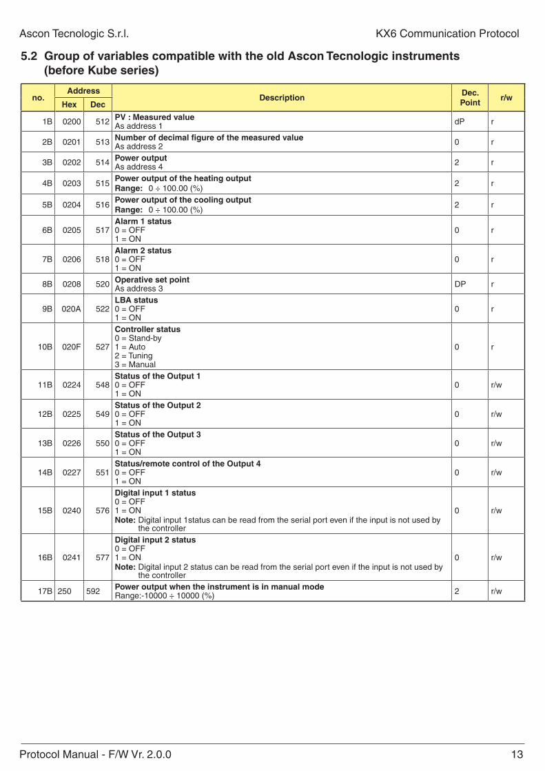
5.2 group of variables compatible with the old ascon tecnologic instruments (before Kube series)
no.address
DescriptionDec. point
r/whex Dec
1B 0200 512 pV : Measured valueAs address 1 dP r
2B 0201 513 number of decimal figure of the measured valueAs address 2 0 r
3B 0202 514 power outputAs address 4 2 r
4B 0203 515power output of the heating outputrange: 0 ÷ 100.00 (%)
2 r
5B 0204 516power output of the cooling outputrange: 0 ÷ 100.00 (%)
2 r
6B 0205 517alarm 1 status0 = OFF1 = ON
0 r
7B 0206 518alarm 2 status0 = OFF1 = ON
0 r
8B 0208 520 operative set pointAs address 3 DP r
9B 020A 522lBa status0 = OFF1 = ON
0 r
10B 020F 527
Controller status0 = Stand-by1 = Auto2 = Tuning3 = Manual
0 r
11B 0224 548Status of the output 10 = OFF1 = ON
0 r/w
12B 0225 549Status of the output 20 = OFF1 = ON
0 r/w
13B 0226 550Status of the output 30 = OFF1 = ON
0 r/w
14B 0227 551Status/remote control of the output 40 = OFF1 = ON
0 r/w
15B 0240 576
Digital input 1 status0 = OFF1 = ONnote: Digital input 1status can be read from the serial port even if the input is not used by
the controller
0 r/w
16B 0241 577
Digital input 2 status 0 = OFF1 = ONnote: Digital input 2 status can be read from the serial port even if the input is not used by
the controller
0 r/w
17B 250 592 power output when the instrument is in manual modeRange:-10000 ÷ 10000 (%) 2 r/w
14 Protocol Manual - F/W Vr. 2.0.0
KX6 Communication Protocol Ascon Tecnologic S.r.l.
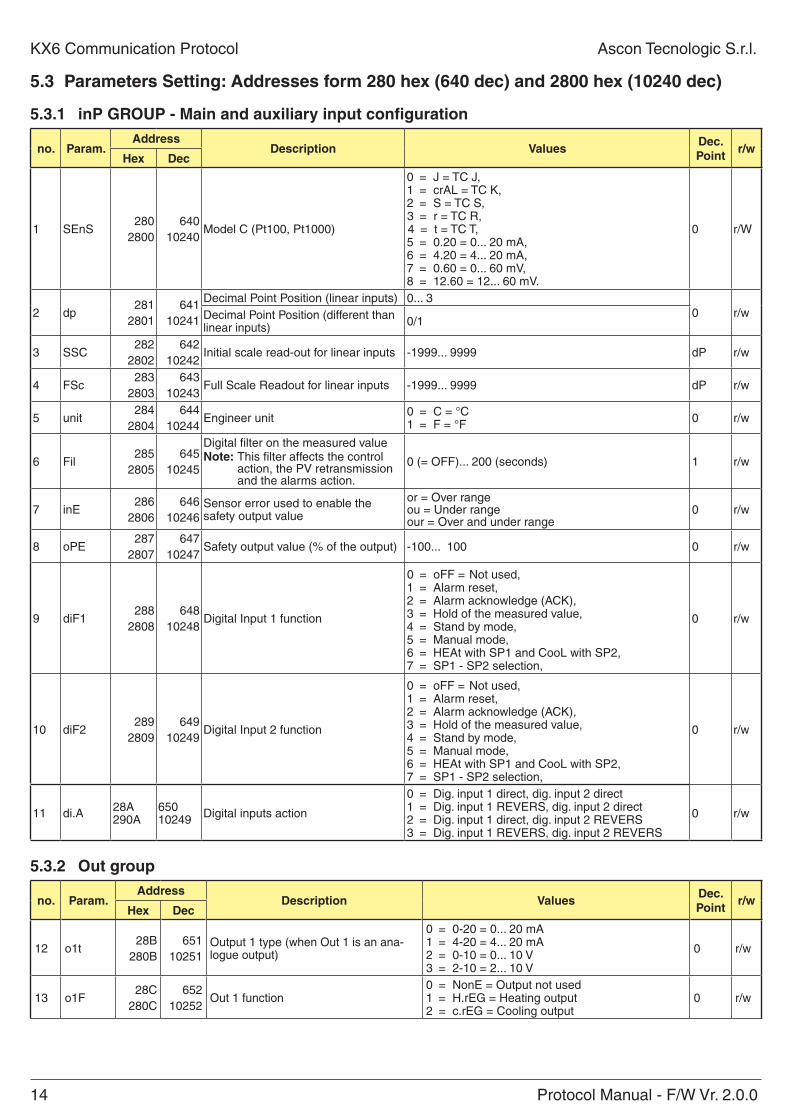
5.3 parameters Setting: addresses form 280 hex (640 dec) and 2800 hex (10240 dec)
5.3.1 inp groUp - Main and auxiliary input configuration
no. param.address
Description ValuesDec. point
r/whex Dec
1 SEnS280
2800640
10240Model C (Pt100, Pt1000)
0 = J = TC J,1 = crAL = TC K,2 = S = TC S,3 = r = TC R,4 = t = TC T,5 = 0.20 = 0... 20 mA,6 = 4.20 = 4... 20 mA,7 = 0.60 = 0... 60 mV,8 = 12.60 = 12... 60 mV.
0 r/W
2 dp281
2801641
10241
Decimal Point Position (linear inputs) 0... 30 r/wDecimal Point Position (different than
linear inputs) 0/1
3 SSC282
2802642
10242Initial scale read-out for linear inputs -1999... 9999 dP r/w
4 FSc283
2803643
10243Full Scale Readout for linear inputs -1999... 9999 dP r/w
5 unit284
2804644
10244Engineer unit 0 = C = °C
1 = F = °F 0 r/w
6 Fil285
2805645
10245
Digital filter on the measured valuenote: This filter affects the control
action, the PV retransmission and the alarms action.
0 (= OFF)... 200 (seconds) 1 r/w
7 inE286
2806646
10246Sensor error used to enable the safety output value
or = Over rangeou = Under rangeour = Over and under range
0 r/w
8 oPE287
2807647
10247Safety output value (% of the output) -100... 100 0 r/w
9 diF1288
2808648
10248Digital Input 1 function
0 = oFF = Not used,1 = Alarm reset,2 = Alarm acknowledge (ACK),3 = Hold of the measured value,4 = Stand by mode,5 = Manual mode,6 = HEAt with SP1 and CooL with SP2,7 = SP1 - SP2 selection,
0 r/w
10 diF2289
2809649
10249Digital Input 2 function
0 = oFF = Not used,1 = Alarm reset,2 = Alarm acknowledge (ACK),3 = Hold of the measured value,4 = Stand by mode,5 = Manual mode,6 = HEAt with SP1 and CooL with SP2,7 = SP1 - SP2 selection,
0 r/w
11 di.A 28A290A
65010249 Digital inputs action
0 = Dig. input 1 direct, dig. input 2 direct1 = Dig. input 1 REVERS, dig. input 2 direct2 = Dig. input 1 direct, dig. input 2 REVERS3 = Dig. input 1 REVERS, dig. input 2 REVERS
0 r/w
5.3.2 out group
no. param.address
Description ValuesDec. point
r/whex Dec
12 o1t28B
280B651
10251Output 1 type (when Out 1 is an ana-logue output)
0 = 0-20 = 0... 20 mA1 = 4-20 = 4... 20 mA2 = 0-10 = 0... 10 V3 = 2-10 = 2... 10 V
0 r/w
13 o1F28C
280C652
10252Out 1 function
0 = NonE = Output not used1 = H.rEG = Heating output2 = c.rEG = Cooling output
0 r/w
Protocol Manual - F/W Vr. 2.0.0 15
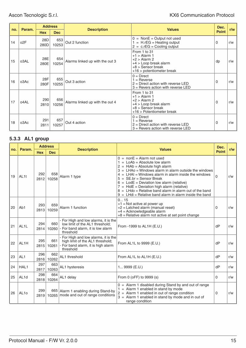
Ascon Tecnologic S.r.l. KX6 Communication Protocol
no. param.address
Description ValuesDec. point
r/whex Dec
14 o2F28D
280D653
10253Out 2 function
0 = NonE = Output not used1 = H.rEG = Heating output2 = c.rEG = Cooling output
0 r/w
15 o3AL28E
280E654
10254Alarms linked up with the out 3
From 1 to 31+1 > Alarm 1+2 > Alarm 2+4 > Loop break alarm+8 > Sensor break +16 > potentiometer break
dp r/w
16 o3Ac28F
280F655
10255Out 3 action
0 = Direct1 = Reverse2 = Direct action with reverse LED3 = Revers action with reverse LED
0 r/w
17 o4AL290
2810656
10256Alarms linked up with the out 4
From 1 to 31+1 > Alarm 1+2 > Alarm 2+4 > Loop break alarm+8 > Sensor break +16 > Potentiometer break
0 r/w
18 o3Ac291
2811657
10257Out 4 action
0 = Direct1 = Reverse2 = Direct action with reverse LED3 = Revers action with reverse LED
0 r/w
5.3.3 al1 group
no. param.address
Description ValuesDec. point
r/whex Dec
19 AL1t292
2812658
10258Alarm 1 type
0 = nonE = Alarm not used1 = LoAb = Absolute low alarm2 = HiAb = Absolute high alarm3 = LHAo = Windows alarm in alarm outside the windows4 = LHAI = Windows alarm in alarm inside the windows5 = SE.br = Sensor Break6 = LodE = Deviation low alarm (relative)7 = HidE = Deviation high alarm (relative)8 = LHdo = Relative band alarm in alarm out of the band9 = LHdi = Relative band alarm in alarm inside the band
0 r/w
20 Ab1293
2813659
10259Alarm 1 function
0... 15+1 = Not active at power up+2 = Latched alarm (manual reset)+4 = Acknowledgeable alarm+8 = Relative alarm not active at set point change
0 r/w
21 AL1L294
2814660
10260
- For High and low alarms, it is the low limit of the AL1 threshold;
- For band alarm, it is low alarm threshold
From -1999 to AL1H (E.U.) dP r/w
22 AL1H295
2815661
10261
- For High and low alarms, it is the high limit of the AL1 threshold;
- For band alarm, it is high alarm threshold
From AL1L to 9999 (E.U.) dP r/w
23 AL1296
2816662
10262AL1 threshold From AL1L to AL1H (E.U.) dP r/w
24 HAL1297
2817663
10263AL1 hysteresis 1... 9999 (E.U.) dP r/w
25 AL1d298
2818664
10264AL1 delay From 0 (oFF) to 9999 (s) 0 r/w
26 AL1o299
2819665
10265Alarm 1 enabling during Stand-by mode and out of range conditions
0 = Alarm 1 disabled during Stand by and out of range1 = Alarm 1 enabled in stand by mode2 = Alarm 1 enabled in out of range condition3 = Alarm 1 enabled in stand by mode and in out of
range condition
0 r/w
16 Protocol Manual - F/W Vr. 2.0.0
KX6 Communication Protocol Ascon Tecnologic S.r.l.
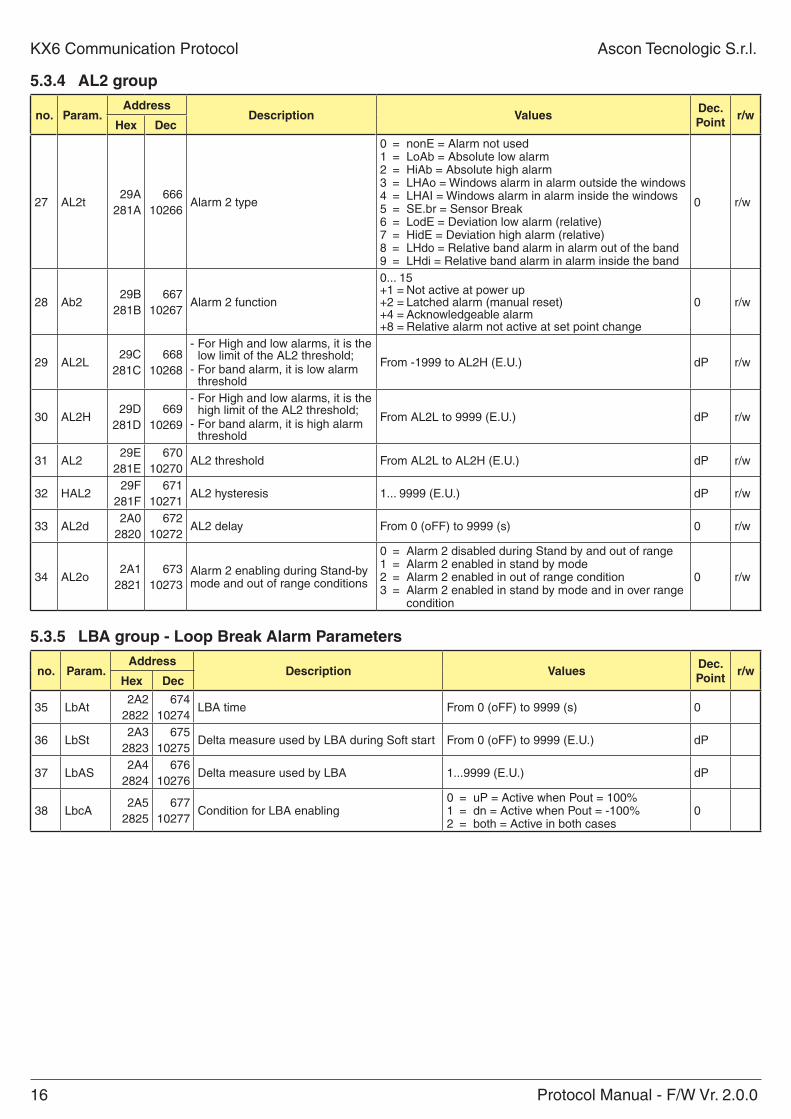
5.3.4 al2 group
no. param.address
Description ValuesDec. point
r/whex Dec
27 AL2t29A
281A666
10266Alarm 2 type
0 = nonE = Alarm not used1 = LoAb = Absolute low alarm2 = HiAb = Absolute high alarm3 = LHAo = Windows alarm in alarm outside the windows4 = LHAI = Windows alarm in alarm inside the windows5 = SE.br = Sensor Break6 = LodE = Deviation low alarm (relative)7 = HidE = Deviation high alarm (relative)8 = LHdo = Relative band alarm in alarm out of the band9 = LHdi = Relative band alarm in alarm inside the band
0 r/w
28 Ab229B
281B667
10267Alarm 2 function
0... 15+1 = Not active at power up+2 = Latched alarm (manual reset)+4 = Acknowledgeable alarm+8 = Relative alarm not active at set point change
0 r/w
29 AL2L29C
281C668
10268
- For High and low alarms, it is the low limit of the AL2 threshold;
- For band alarm, it is low alarm threshold
From -1999 to AL2H (E.U.) dP r/w
30 AL2H29D
281D669
10269
- For High and low alarms, it is the high limit of the AL2 threshold;
- For band alarm, it is high alarm threshold
From AL2L to 9999 (E.U.) dP r/w
31 AL229E
281E670
10270AL2 threshold From AL2L to AL2H (E.U.) dP r/w
32 HAL229F
281F671
10271AL2 hysteresis 1... 9999 (E.U.) dP r/w
33 AL2d2A0
2820672
10272AL2 delay From 0 (oFF) to 9999 (s) 0 r/w
34 AL2o2A1
2821673
10273Alarm 2 enabling during Stand-by mode and out of range conditions
0 = Alarm 2 disabled during Stand by and out of range1 = Alarm 2 enabled in stand by mode2 = Alarm 2 enabled in out of range condition3 = Alarm 2 enabled in stand by mode and in over range
condition
0 r/w
5.3.5 lBa group - loop Break alarm parameters
no. param.address
Description ValuesDec. point
r/whex Dec
35 LbAt2A2
2822674
10274LBA time From 0 (oFF) to 9999 (s) 0
36 LbSt2A3
2823675
10275Delta measure used by LBA during Soft start From 0 (oFF) to 9999 (E.U.) dP
37 LbAS2A4
2824676
10276Delta measure used by LBA 1...9999 (E.U.) dP
38 LbcA2A5
2825677
10277Condition for LBA enabling
0 = uP = Active when Pout = 100%1 = dn = Active when Pout = -100%2 = both = Active in both cases
0
Protocol Manual - F/W Vr. 2.0.0 17
Ascon Tecnologic S.r.l. KX6 Communication Protocol
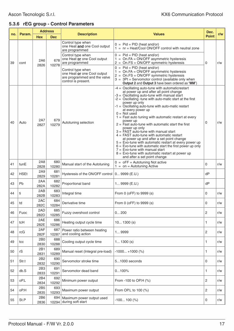
5.3.6 reg group - Control parameters
no. param.address
Description ValuesDec. point
r/whex Dec
39 cont 2A6
2826678
10278
Control type when one Heat and one Cool output are programmed
0 = Pid = PID (heat and/or)1 = nr = Heat/Cool ON/OFF control with neutral zone
0 r/w
Control type when one Heat or one Cool output are programmed
0 = Pid = PID (heat and/or)1 = On.FA = ON/OFF asymmetric hysteresis2 = On.FS = ON/OFF symmetric hysteresis
Control type when one Heat or one Cool output are programmed and the valve control is present.
0 = Pid = PID (heat and/or)1 = On.FA = ON/OFF asymmetric hysteresis2 = On.FS = ON/OFF symmetric hysteresis3 = 3Pt = Servomotor control (available only when
output 2 and output 3 have been ordered as “MM”)
40 Auto 2A7
2827679
10279Autotuning selection
-4 = Oscillating auto-tune with automaticrestart at power up and after all point change-3 = Oscillating auto-tune with manual start-2 = Oscillating -tune with auto-matic start at the first power up only-1 = Oscillating auto-tune with auto-matic restart at every power up 0 = Not used 1 = Fast auto tuning with automatic restart at every power up 2 = Fast auto-tune with automatic start the first power up only 3 = FAST auto-tune with manual start 4 = FAST auto-tune with automatic restart at power up and after a set point change 5 = Evo-tune with automatic restart at every power up 6 = Evo-tune with automatic start the first power up only 7 = Evo-tune with manual start 8 = Evo-tune with automatic restart at power up and after a set point change
0 r/w
41 tunE2A8
2828680
10280Manual start of the Autotuning 0 = oFF = Autotuning Not active
1 = on = Autotuning Active 0 r/w
42 HSEt 2A9
2829681
10281Hysteresis of the ON/OFF control 0... 9999 (E.U.) dP
43 Pb 2AA
282A682
10282Proportional band 1... 9999 (E.U.) dP
44 ti 2AB
282B683
10283Integral time From 0 (oFF) to 9999 (s) 0 r/w
45 td2AC
282C684
10284Derivative time From 0 (oFF) to 9999 (s) 0 r/w
46 Fuoc 2AD
282D685
10285Fuzzy overshoot control 0... 200 2 r/w
47 tcH2AE
282E686
10286Heating output cycle time 10... 1300 (s) 1 r/w
48 rcG2AF
282F687
10287Power ratio between heating and cooling action 1... 9999 2 r/w
49 tcc2B0
2830688
10288Cooling output cycle time 1... 1300 (s) 1 r/w
50 rS 2B1
2831689
10289Manual reset (Integral pre-load) -1000... +1000 (%) 1 r/w
51 Str.t2B2
2832690
10290Servomotor stroke time 5...1000 seconds 0 r/w
52 db.S2B3
2833691
10291Servomotor dead band 0...100% 1 r/w
53 oP.L2B4
2834692
10292Minimum power output From -100 to OP.H (%) 2 r/w
54 oP.H2B5
2835693
10293Maximum power output From OP.L to 100 (%) 2 r/w
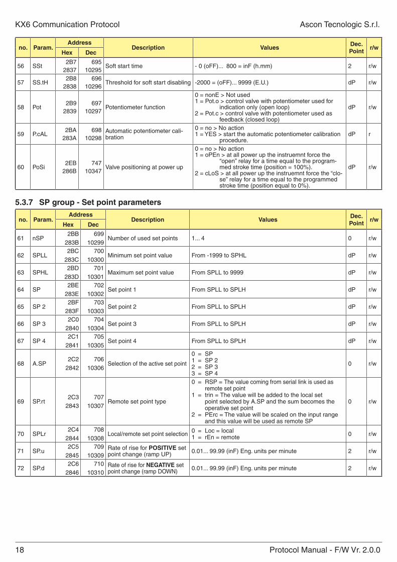
55 St.P2B6
2836694
10294Maximum power output used during soft start -100... 100 (%) 0 r/w
18 Protocol Manual - F/W Vr. 2.0.0
KX6 Communication Protocol Ascon Tecnologic S.r.l.
no. param.address
Description ValuesDec. point
r/whex Dec
56 SSt2B7
2837695
10295Soft start time - 0 (oFF)... 800 = inF (h.mm) 2 r/w
57 SS.tH2B8
2838696
10296Threshold for soft start disabling -2000 = (oFF)... 9999 (E.U.) dP r/w
58 Pot2B9
2839697
10297Potentiometer function
0 = nonE > Not used1 = Pot.o > control valve with potentiometer used for
indication only (open loop)2 = Pot.c > control valve with potentiometer used as
feedback (closed loop)
dP r/w
59 P.cAL2BA
283A698
10298Automatic potentiometer cali-bration
0 = no > No action1 = YES > start the automatic potentiometer calibration
procedure.dP r
60 PoSi2EB
286B747
10347Valve positioning at power up
0 = no > No action1 = oPEn > at all power up the instruemnt force the
“open” relay for a time equal to the program-med stroke time (position = 100%).
2 = cLoS > at all power up the instruemnt force the “clo-se” relay for a time equal to the programmed stroke time (position equal to 0%).
dP r/w
5.3.7 Sp group - Set point parameters
no. param.address
Description ValuesDec. point
r/whex Dec
61 nSP2BB
283B699
10299Number of used set points 1... 4 0 r/w
62 SPLL2BC
283C700
10300Minimum set point value From -1999 to SPHL dP r/w
63 SPHL2BD
283D701
10301Maximum set point value From SPLL to 9999 dP r/w
64 SP2BE
283E702
10302Set point 1 From SPLL to SPLH dP r/w
65 SP 22BF
283F703
10303Set point 2 From SPLL to SPLH dP r/w
66 SP 32C0
2840704
10304Set point 3 From SPLL to SPLH dP r/w
67 SP 42C1
2841705
10305Set point 4 From SPLL to SPLH dP r/w
68 A.SP2C2
2842706
10306Selection of the active set point
0 = SP1 = SP 22 = SP 33 = SP 4
0 r/w
69 SP.rt2C3
2843707
10307Remote set point type
0 = RSP = The value coming from serial link is used as remote set point
1 = trin = The value will be added to the local set point selected by A.SP and the sum becomes the operative set point
2 = PErc = The value will be scaled on the input range and this value will be used as remote SP
0 r/w
70 SPLr2C4
2844708
10308Local/remote set point selection 0 = Loc = local
1 = rEn = remote 0 r/w
71 SP.u2C5
2845709
10309Rate of rise for poSitiVe set point change (ramp UP) 0.01... 99.99 (inF) Eng. units per minute 2 r/w
72 SP.d2C6
2846710
10310Rate of rise for negatiVe set point change (ramp DOWN) 0.01... 99.99 (inF) Eng. units per minute 2 r/w
Protocol Manual - F/W Vr. 2.0.0 19
Ascon Tecnologic S.r.l. KX6 Communication Protocol
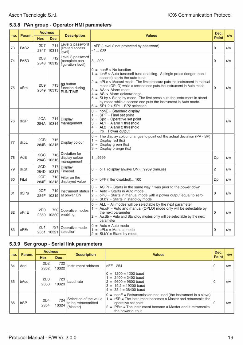
5.3.8 pan group - operator hMi parameters
no. param.address
Description ValuesDec. point
r/whex Dec
73 PAS22C7
2847711
10311
Level 2 password (limited access level)
- oFF (Level 2 not protected by password) - 1... 200
0 r/w
74 PAS32C8
2848712
10312
Level 3 password (complete con-figuration level)
3... 200 0 r/w
75 uSrb2C9
2849713
10313
button function during RUN TIME
0 = nonE > No function1 = tunE > Auto-tune/self-tune enabling. A single press (longer than 1
second) starts the auto-tune2 = oPLo > Manual mode. The first pressure puts the instrument in manual
mode (OPLO) while a second one puts the instrument in Auto mode3 = AAc > Alarm reset4 = ASi > Alarm acknowledge5 = St.by > Stand by mode. The first press puts the instrument in stand
by mode while a second one puts the instrument in Auto mode.6 = SP1.2 > SP1 - SP2 selection
0 r/w
76 diSP2CA
284A714
10314Display management
0 = nonE = Standard display1 = SPF = Final set point2 = Spo = Operative set point3 = AL1 = Alarm 1 threshold4 = AL2 = Alarm 2 threshold5 = Po = Power output.
r/w
77 di.cL2CB
284B715
10315Display colour
0 = The display colour changes to point out the actual deviation (PV - SP)1 = Display red (fix)2 = Display green (fix)3 = Display orange (fix)
78 AdE2CC
284C716
10316
Deviation for display colour management
1... 9999 Dp r/w
79 di.St2CD
284D717
10317Display Timeout 0 = oFF (display always ON)... 9959 (mm.ss) 2 r/w
80 FiLd2CE
284E718
10318Filter on the displayed value 0 = oFF (filter disabled)... 100 Dp r/w
81 dSPu2CF
284F719
10319Instrument status at power ON
0 = AS.Pr = Starts in the same way it was prior to the power down1 = Auto = Starts in Auto mode2 = oP.0 = Starts in manual mode with a power output equal to zero3 = St.bY = Starts in stand-by mode
0 r/w
82 oPr.E2D0
2850720
10320Operative modes enabling
0 = ALL = All modes will be selectable by the next parameter1 = Au.oP = Auto and manual (OPLO) mode only will be selectable by
the next parameter2 = Au.Sb = Auto and Stand-by modes only will be selectable by the next
parameter
0 r/w
83 oPEr2D1
2851721
10321Operative mode selection
0 = Auto = Auto mode1 = oPLo = Manual mode2 = St.bY = Stand by mode
0 r/w
5.3.9 Ser group - Serial link parameters
no. param.address
Description ValuesDec. point
r/whex Dec
84 Add2D2
2852722
10322Instrument address oFF... 254 0 r/w
85 bAud2D3
2853723
10323baud rate
0 = 1200 = 1200 baud1 = 2400 = 2400 baud2 = 9600 = 9600 baud3 = 19.2 = 19200 baud4 = 38.4 = 38400 baud
0 r/w
86 trSP2D4
2854724
10324
Selection of the value to be retransmitted (Master)
0 = nonE = Retransmission not used (the instrument is a slave)1 = rSP = The instrument becomes a Master and retransmits the
operative set point2 = PErc = The instrument become a Master and it retransmits
the power output
0 r/w
20 Protocol Manual - F/W Vr. 2.0.0
KX6 Communication Protocol Ascon Tecnologic S.r.l.
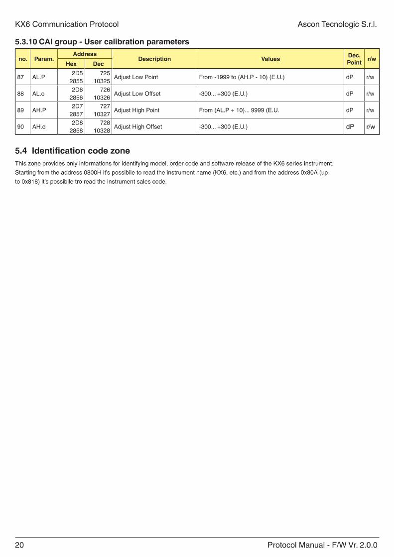
5.3.10 Cal group - User calibration parameters
no. param.address
Description ValuesDec. point
r/whex Dec
87 AL.P2D5
2855725
10325Adjust Low Point From -1999 to (AH.P - 10) (E.U.) dP r/w
88 AL.o2D6
2856726
10326Adjust Low Offset -300... +300 (E.U.) dP r/w
89 AH.P2D7
2857727
10327Adjust High Point From (AL.P + 10)... 9999 (E.U. dP r/w
90 AH.o2D8
2858728
10328Adjust High Offset -300... +300 (E.U.) dP r/w
5.4 identification code zoneThis zone provides only informations for identifying model, order code and software release of the KX6 series instrument.
Starting from the address 0800H it’s possibile to read the instrument name (KX6, etc.) and from the address 0x80A (up
to 0x818) it’s possibile tro read the instrument sales code.
Protocol Manual - F/W Vr. 2.0.0 21
Ascon Tecnologic S.r.l. KX6 Communication Protocol
6 perforManCeAfter receiving a valid request the instrument prepares the reply, then sends it back to the master station according to the following specifications:
– A minimum time is granted greater or equal 3 characters time (depending on adopted baud rate, allowing line direction reversal)
– The reply is ready to be transmitted in less then 20 ms except in case 3;
A 20 ms silence on the line is necessary to recover from abnormal contitions or erroneous messages; this means that a time less than 20 ms is allowed between any two characters in the same message.

22 Protocol Manual - F/W Vr. 2.0.0
KX6 Communication Protocol Ascon Tecnologic S.r.l.
All rights reserved. No parts of this publication may be reproduced, in any form, without Ascon Tecnolo-gic S.r.l. written permission.Every care has been taken preparing this manual; the document has been carefully reviewed for techni-cal accuracy. In the event that technical or typographical errors exist Ascon Tecnologic S.r.l. reserves the right to make changes without any notice.In no event shall Ascon Tecnologic S.r.l. be liable for any damages arising out of or related to this docu-ment or the information contained in it.If errors are suspected, please contact Ascon Tecnologic S.r.l. at the above address.
Ascon Tecnologic S.r.l.Via Indipendenza, 56
27029 Vigevano (PV) Italia
Tel. ++39/0381/69871Fax ++39/0381/698730