Embed Size (px)
DESCRIPTION
Serial Communication Interface (SCI). Presented by: Lakmal Kaviratna Thomas Herrmann Nicolaas Ostendorf 13 November 2012. Lakmal Kaviratna. Data Transmission Types. Transmitting Data b 1 b 2 b 3 b 4 b 5 b 6 b 7 b 8. -- Bit i. i. Transmitting Data b 1 b 2 b 3 b 4 b 5 b 6 b 7 b 8. 1. - PowerPoint PPT Presentation
Citation preview

Serial Communication Interface(SCI)
Presented by:
Lakmal KaviratnaThomas HerrmannNicolaas Ostendorf
13 November 2012

Data Transmission Types
Transmitting Datab1b2b3b4b5b6b7b8
1 2 3 4 5 6 7 8
Received Datab1b2b3b4b5b6b7b8
Parallel
1
2
3
4
5
6
7
8
Received Datab1b2b3b4b5b6b7b8
Transmitting Datab1b2b3b4b5b6b7b8
Serial
i -- Bit i
Lakmal Kaviratna

Parallel vs Serial Data TransmissionParallel Serial
• More Transfer Wires • Less Transfer Wires
• Bits MUST be Synchronized • Bits transferred one at a time
• Faster data Transmission • Slower Data Transmission
• More Expensive • Cheaper
• Examples Include:• IDE hard-disk connectors• PCI expansion ports
• Examples Include:• USB• FireWire
Lakmal Kaviratna

Types of Serial Communication• Synchronous Serial Communication
– Transmitter and Receiver have synchronized clocks– Data must be sent constantly in order for them to stay
synchronized– Any data not sent on a regular clock cycle is considered
noise– Transmission parameters are set up before sending data– 30% faster than asynchronous transmission for large
continuous blocks of data– Clock rate determines data transfer rate
Receiver Transmitter
Δt
-- Bit of Data
Lakmal Kaviratna

Types of Serial Communication• Asynchronous Communication• Transmitter and receiver do not have
synchronized clocks and act independently• Simpler and less expensive than synchronous • Start, Stop and Parity “caution” bits are sent
with each word of data
Transmitter Transmitter
-- Start Bit -- Parity Bit -- Stop Bit -- Bit of Data
Lakmal Kaviratna

Synchronous vs Asynchronous Serial Communication
Synchronous Asynchronous
Operation • Synchronized Clocks • Start, Stop, and Parity bits
Hardware Cost • Expensive • Cheap
Hardware Complexity • Complex • Simple
Speed • Faster • Slower
Overhead • Low Overhead • High Overhead
Lakmal Kaviratna

Baud and Bit Rates
• Symbol – a pulse representing an integer number of bits• Baud (Bd) – Rate which Symbols are transferred.
(Symbols/second)– The number of bits per Symbol is Hardware Specific
• Bit rate (bps) – Rate which bits are transmitted. (bits/second)
• Data Throughput (dtp) – Rate which bits of DATA are transmitted. (Characters/second)– Remember: in asynchronous transfer, not all bits are data
(start/stop/parity bits are also present)
Lakmal Kaviratna

Example Baud and Bit Rates• Example: You have an asynchronous serial connection. Assuming 2 bits
per symbol, 9600 bd line speed, 8 bit data format with no parity, 1 start bit and 1 stop bit, calculate the throughput in cps.
h h𝑇 𝑟𝑜𝑢𝑔 𝑝𝑢𝑡=𝐵𝑑∗( ¿𝑏𝑖𝑡𝑠𝑆𝑦𝑚𝑏𝑜𝑙 )∗𝑑𝑡𝑝
h h𝑇 𝑟𝑜𝑢𝑔 𝑝𝑢𝑡=(9600𝑏𝑑)∗ (2𝑏𝑖𝑡𝑠/𝑆𝑦𝑚𝑏𝑜𝑙 )∗( 8 h𝑐 𝑎𝑟𝑎𝑐𝑡𝑒𝑟𝑠10𝑏𝑖𝑡𝑠 )
𝑻𝒉𝒓𝒐𝒖𝒈𝒉𝒑𝒖𝒕=𝟏𝟓𝟑𝟔𝟎𝒅𝒕𝒑
Lakmal Kaviratna

Asynchronous Serial Communication
• Transmitter and Receiver operate independently of each other
• Transmitter must send a Start, Parity, and Stop bit with each package or ‘word’ of Data
• Any signal after a Stop bit and before a Start bit is ignored
Start 0 1 2 3 4 5 6 Parity Stop
Thomas Herrmann

Data Signal Format • Idle State – signal between data• Start Bit – signifies start of data transmission• Data Packet – data being transmitted• Parity Bit – fidelity check of data for receiver• Stop Bit – signifies end of data transmission
• Data – 10-11 bits
Start 0 1 2 3 4 5 6 Parity Stop
Thomas Herrmann

Idle State
• Idle signal is a uniform stream of bits at the idle polarity state
• For the HCS12, the idle state is 1
Start 0 1 2 3 4 5 6 Parity Stop
Thomas Herrmann
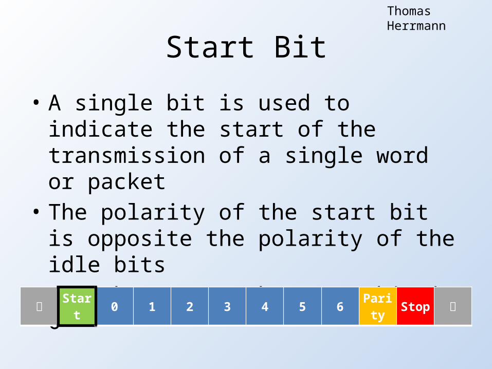
Start Bit
• A single bit is used to indicate the start of the transmission of a single word or packet
• The polarity of the start bit is opposite the polarity of the idle bits
• For the HCS12, the start bit is 0
Start 0 1 2 3 4 5 6 Parity Stop
Thomas Herrmann

Data Bits
• Actual data that is being transmitted• 8-bit mode transmission, typical
– 7 bits of data and 1 parity bit (Used for ASCII)• 9-bit mode transmission, less common
– 8 bits of data and 1 parity bit (Full byte transmission)• The HCS12 requires the least significant bit first
Start 0 1 2 3 4 5 6 Parity Stop
Thomas Herrmann

Parity Bit
• Last bit in data packet used to determine the fidelity of the received signal and check for errors in a transmission– Transmitter calculates parity bit based on data sent– Receiver estimated parity bit with the data received– Receiver compares received parity and estimate
parity
Start 0 1 2 3 4 5 6 Parity Stop
Thomas Herrmann
Parity Bit
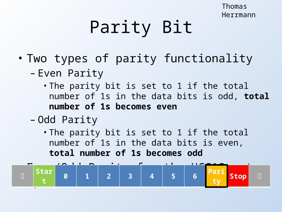
• Two types of parity functionality– Even Parity
• The parity bit is set to 1 if the total number of 1s in the data bits is odd, total number of 1s becomes even
– Odd Parity• The parity bit is set to 1 if the total number of 1s in the
data bits is even, total number of 1s becomes odd
• Even/Odd Parity for the HCS12 set by User Start 0 1 2 3 4 5 6 Parity Stop
Thomas Herrmann

Stop Bit
• Signifies end of packet – necessary for asynchronous transmission
• Can be 1-2 bits• Stop bit polarity is the same as the idle state
polarity• For the HCS12, stop bit is 1
Start 0 1 2 3 4 5 6 Parity Stop
Thomas Herrmann

Example 1
Construct the asynchronous signal for the transmission of 7516 for the HCS12 with 8-bit mode, even parity, and one stop bit
7516 = 0111 01012
Thomas Herrmann
1 0 1 0 1 0 1 1 1 1 1 1
Idle Start 0-bit 1-bit 2-bit 3-bit 4-bit 5-bit 6-bit Parity Stop Idle
1
0

Example 2
Construct the asynchronous signal for the transmission of 5A16 for the HCS12 with 8-bit mode, even parity, and one stop bit
5A16 = 0101 10102
Thomas Herrmann
1 0 0 1 0 1 1 0 1 0 1 1
Idle Start 0-bit 1-bit 2-bit 3-bit 4-bit 5-bit 6-bit Parity Stop Idle
1
0
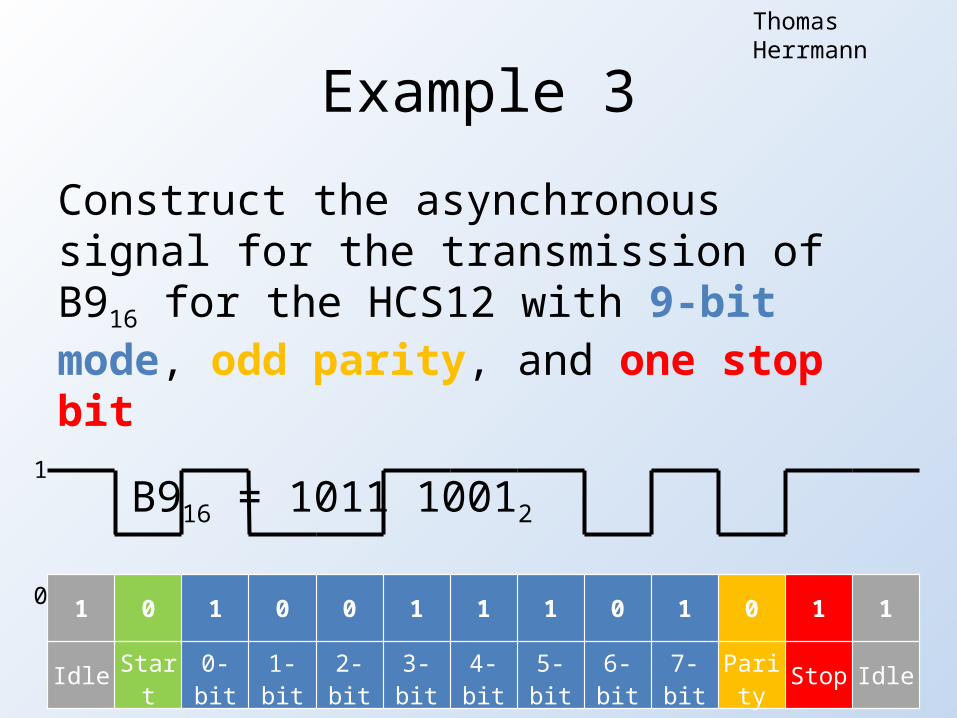
Example 3
Construct the asynchronous signal for the transmission of B916 for the HCS12 with 9-bit mode, odd parity, and one stop bit
B916 = 1011 10012
Thomas Herrmann
1 0 1 0 0 1 1 1 0 1 0 1 1
Idle Start 0-bit 1-bit 2-bit 3-bit 4-bit 5-bit 6-bit 7-bit Parity Stop Idle
1
0

Types of Error
• Receiver Overrun
• Noise Error
• Frame Error
• Parity Error
Thomas Herrmann

Receiver Overrun
• Software fails to process the SCI data register before it receives the next frame
• Data in the shift register is lost• Data already in the SCI data registers is not
affected
21
Thomas Herrmann

Noise Error
22
Thomas Herrmann
• Signal noise can cause the receiver to incorrectly read a start bit or false data
• This can be compensated by sampling at a higher frequency that the incoming signal– Multiple reading can be taken of each transmitted
bit– These readings are averaged to determine the
intended transmission

Frame Error• Occurs when stop bit is
not where receiver expects it to be
• Detected when a logic 0 is accepted as the stop bit
• Ex: The fourth bit is skipped and stop bit is one bit before it should be
23
1 2 3 4 5 6 7
Thomas Herrmann
Parity Error
• The transmitter determines and send the correct parity bit
• The receiver determines what the parity bit should be based on the signal received
• If the transmitter and receiver parity bits do not match, then there is a known error
• This does not account for an even number of errors in the data bits

SCI Distinctive Features (S12SCIV2)• Full duplex operation• 13-bit baud rate selection• Programmable 8-bit or 9-bit data format• Separately enabled transmitter and receiver• Programmable transmitter output parity• Two receiver wake up methods• Interrupt driven operation with 8 flags• 8 registers used to control SCI ($00C8 - $00CF)• Uses Port S, pins 0 & 1 for RXD and TXD respectively
• SCI is summarized on pages 383-393 in MC9S12C Family Reference Manual
Nicolaas Ostendorf
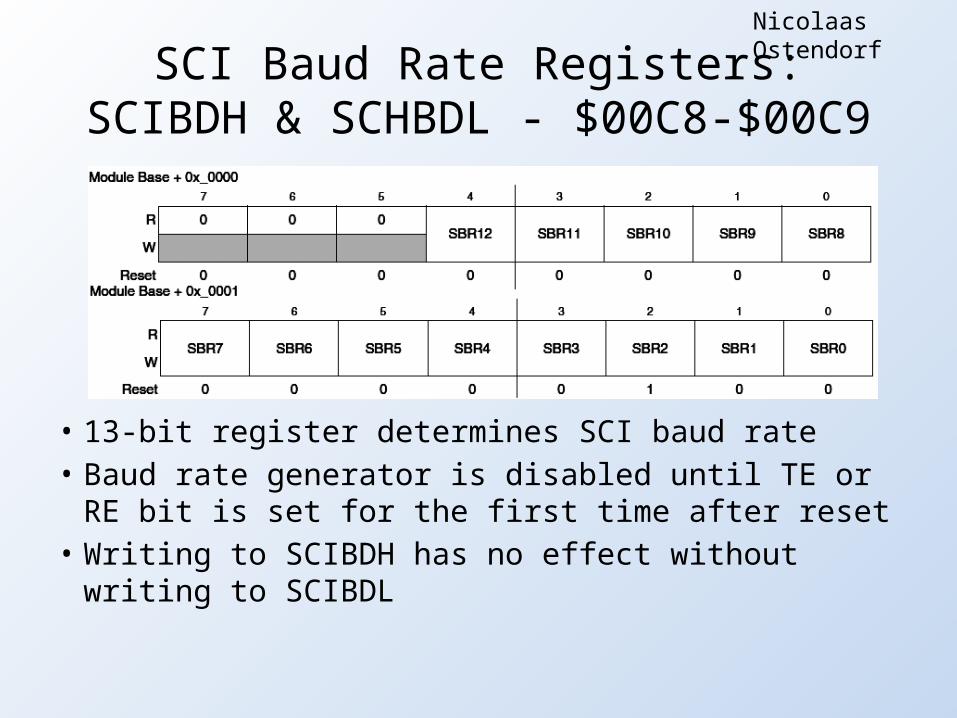
SCI Baud Rate Registers:SCIBDH & SCHBDL - $00C8-$00C9
• 13-bit register determines SCI baud rate• Baud rate generator is disabled until TE or RE bit is set
for the first time after reset• Writing to SCIBDH has no effect without writing to
SCIBDL
Nicolaas Ostendorf

SCI Control Register 1:SCICR1 - $00CA
• Data Format Bit (M) – 0: 8-bit, 1: 9-bit– Both 8-bit and 9-bit data formats have 1 start bit
and 1 stop bit• Parity Enable Bit (PE) – 0: Disabled, 1: Enabled• Parity Type Bit (PT) – 0: Even, 1: Odd
Nicolaas Ostendorf

SCI Control Register 2:SCICR2 - $00CB
• Transmit Interrupt Enable (TIE) – 0: Disables interrupts for transmit data register empty flag, 1: Enables
• Transmit Complete Interrupt Enable (TCIE) – 0: Disables interrupts for transmit complete flag, 1: Enables
• Receiver Interrupt Enable (RIE) – 0: Disables interrupts for receiver full or overrun flags, 1: Enables
• Idle Line Interrupt Enable (ILIE) – 0: Disables interrupts for idle line flag, 1: Enables
• Transmit Enable (TE) – 0: Disables transmitter, 1: Enables• Receiver Enable (RE) – 0: Disables receiver, 1: Enables
Nicolaas Ostendorf

SCI Status Register 1:SCISR1 - $00CC
• Read only register• Transmit Data Register Empty (TDRE) – 0: No byte transferred
to transmit shift register, 1: Byte successfully transferred• Transmit Complete (TC) – 0: Transmission in progress, 1: No
transmission in progress• Receive Data Register Full (RDRF) – 0: No data in SCI data
register, 1: Data in SCI data register
Nicolaas Ostendorf
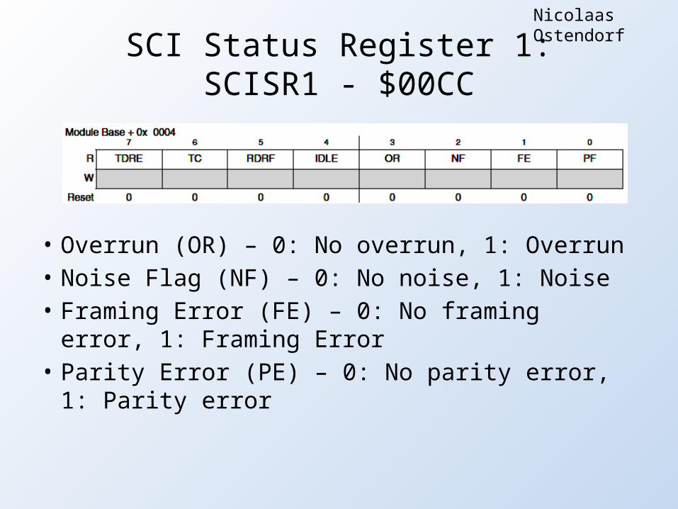
• Overrun (OR) – 0: No overrun, 1: Overrun• Noise Flag (NF) – 0: No noise, 1: Noise• Framing Error (FE) – 0: No framing error, 1:
Framing Error• Parity Error (PE) – 0: No parity error, 1: Parity
error
SCI Status Register 1:SCISR1 - $00CC
Nicolaas Ostendorf
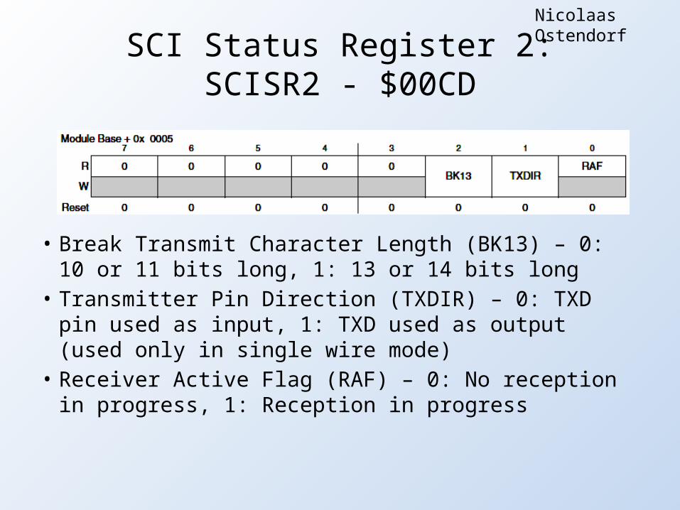
SCI Status Register 2:SCISR2 - $00CD
• Break Transmit Character Length (BK13) – 0: 10 or 11 bits long, 1: 13 or 14 bits long
• Transmitter Pin Direction (TXDIR) – 0: TXD pin used as input, 1: TXD used as output (used only in single wire mode)
• Receiver Active Flag (RAF) – 0: No reception in progress, 1: Reception in progress
Nicolaas Ostendorf

SCI Data Registers:SCIRDH & SCIRDL - $00CE-$00CF
• SCIRDL contains incoming bytes of data from serial port
• R8 – Bit 8 of received data in 9-bit format• T8 – Bit 8 of transmitted data in 9-bit format
Nicolaas Ostendorf

Example• First calculate baud rate:
– Assume 8MHz bus and desired baud rate is 9600
• Desired value for SCIBR is 52• You will have some error margin
– Exact solution: 52.0833– Actual baud rate: 9615.3 (0.160% error)
0]:SCIBR[1216
clockmoduleSCIratebaudSCI
Nicolaas Ostendorf
Example
• Write SCIBR ($34) to SCI Baud Rate Registers (SCIBDH/SCIBDL)
• Default values work for 8-bit, no parity, and no interrupts
• Enable transmit and receive in SCICR2• Read from SCIDRL to receive 8-bit data• Write data to SCIDRL to send 8-bit data
Nicolaas Ostendorf

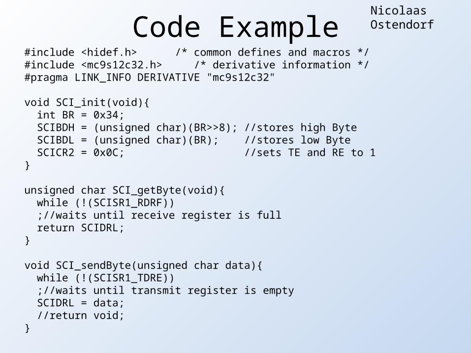
#include <hidef.h> /* common defines and macros */#include <mc9s12c32.h> /* derivative information */#pragma LINK_INFO DERIVATIVE "mc9s12c32"
void SCI_init(void){ int BR = 0x34; SCIBDH = (unsigned char)(BR>>8); //stores high Byte SCIBDL = (unsigned char)(BR); //stores low Byte SCICR2 = 0x0C; //sets TE and RE to 1}
unsigned char SCI_getByte(void){ while (!(SCISR1_RDRF)) ;//waits until receive register is full return SCIDRL;}
void SCI_sendByte(unsigned char data){ while (!(SCISR1_TDRE)) ;//waits until transmit register is empty SCIDRL = data; //return void;}
void main(void) { //variable declarations must go at beginning
EnableInterrupts; MISC = 0x03; PEAR = 0x0C; MODE = 0xE2; //Call function to setup SCI SCI_init(); //Main loop for(;;) { SCI_sendByte(SCI_getByte()); } /* wait */ /* please make sure that you never leave this function */}
Code Example: Help set up SCI in CodeWarrior
Nicolaas Ostendorf
#include <hidef.h> /* common defines and macros */#include <mc9s12c32.h> /* derivative information */#pragma LINK_INFO DERIVATIVE "mc9s12c32"
void SCI_init(void){ int BR = 0x34; SCIBDH = (unsigned char)(BR>>8); //stores high Byte SCIBDL = (unsigned char)(BR); //stores low Byte SCICR2 = 0x0C; //sets TE and RE to 1}
unsigned char SCI_getByte(void){ while (!(SCISR1_RDRF)) ;//waits until receive register is full return SCIDRL;}
void SCI_sendByte(unsigned char data){ while (!(SCISR1_TDRE)) ;//waits until transmit register is empty SCIDRL = data; //return void;}
Code ExampleNicolaas Ostendorf

void main(void) { //variable declarations must go at beginning EnableInterrupts; MISC = 0x03; PEAR = 0x0C; MODE = 0xE2; //Call function to setup SCI SCI_init(); //Main loop for(;;) { SCI_sendByte(SCI_getByte()); } /* wait */ /* please make sure that you never leave this function */}
Code ExampleNicolaas Ostendorf

Questions?

References
• MC9S12C Family Reference Manual• Past Student Lectures• http://en.wikipedia.org/wiki/Symbol_rate• http://en.wikipedia.org/wiki/Baud