Embed Size (px)
Citation preview
Serial Communication
ETEC 6416
What is serial
• In serial communication we are transmitting the data/information bit after bit (only one bit goes through in a particular moment).
• In parallel communication we are transmitting a number of bits at once from one computer to the second computer.
Serial vs parallel
• Parallel communication is faster• Serial communication is more reliable• Parallel communication requires the use of
more pins on the microcontroller• Applications for parallel communication
include RF Digital to Analogue ICs for RF communication
• Applications for Serial include GPS, GSM etc
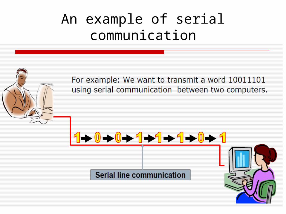
An example of serial communication
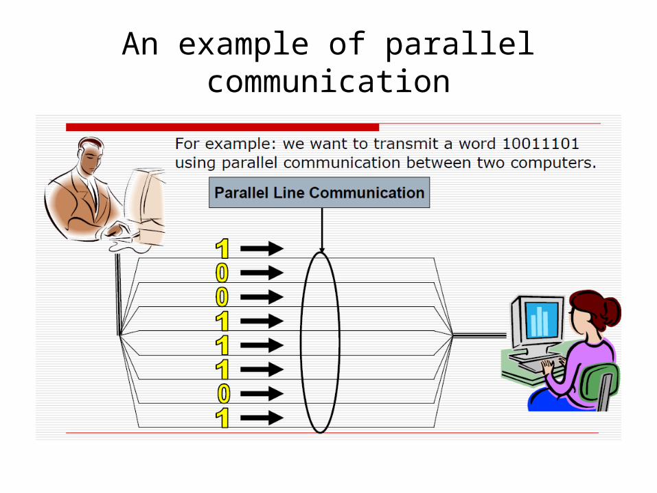
An example of parallel communication
Synchronous/AsynchronousCommunication
• Synchronous communication:– The information is transmitted from the transmitter is in sequence, bit after
bit, with fixed baud rate, when the clock frequency along with the bits are transmitted to the receiver. This means that the transmitter and the receiver are synchronized between them by the same clock frequency.
• Asynchronous communication:– The transmitter and the receiver refraining to broadcast long sequences of
bits because there isn't a full synchronization between the transmitter that sends the data and the receiver that receives the data. In this case, the information is divided into frames, in the size of byte. Each one of the frame has a “Start” bit and a “Stop” bit. “Start” bit marks the beginning of a new frame, “Stop” bit marks the end. Frames of information must not necessarily be transmitted at equal time space, since they are independent of the clock.
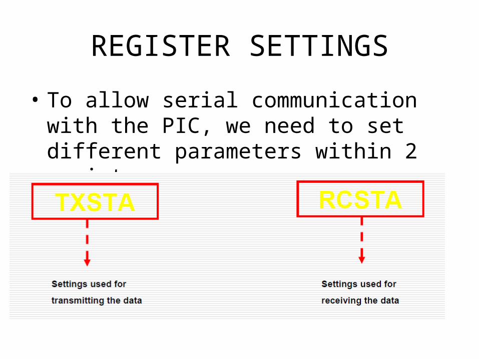
REGISTER SETTINGS
• To allow serial communication with the PIC, we need to set different parameters within 2 registers:
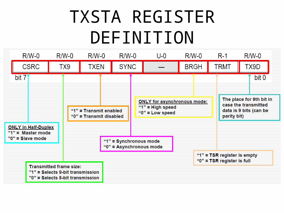
TXSTA REGISTER DEFINITION
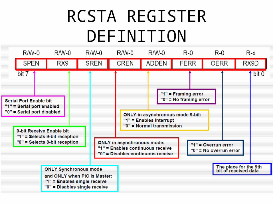
RCSTA REGISTER DEFINITION
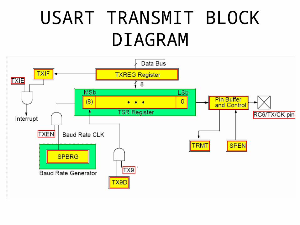
USART TRANSMIT BLOCK DIAGRAM
Registers and Control lines of thetransmitter
• The information we want to transmit is loaded into register TXREG (8 bits size). In case the transmitted data is 9 bits long, the 9th bit is placed TX9D.– At the same time, the information above is being loaded into
the register TSR, which is used as a temporary buffer before that information is transmitted.
– TXIF – is set then TXREG is empty/free and ready to be loaded with a new information.
– TXIE – is enabling the interrupt in the case TXREG is loaded/filled and TXIF = 1.
– SPBRG – sets the desired baud rate in the system.– TXEN – is enabling the SPBRG.
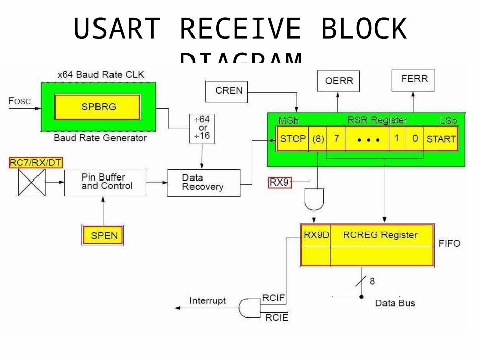
USART RECEIVE BLOCK DIAGRAM
Registers and Control lines ofthe receiver
• The received information is stored in the register RSR
• After receiving the data in the register RSR, the information is loaded at the same time into the register RCREG (8-bit size). In case the received data is 9-bit long, the 9th bit goes into RX9D.
• CREN - continuous receive enable bit
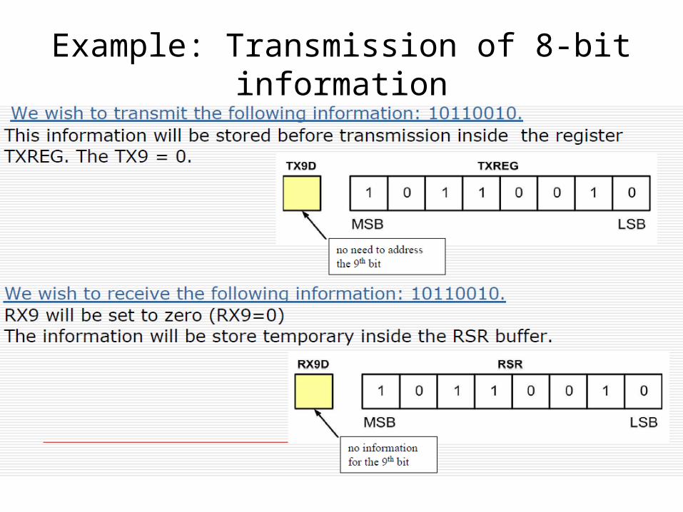
Example: Transmission of 8-bitinformation
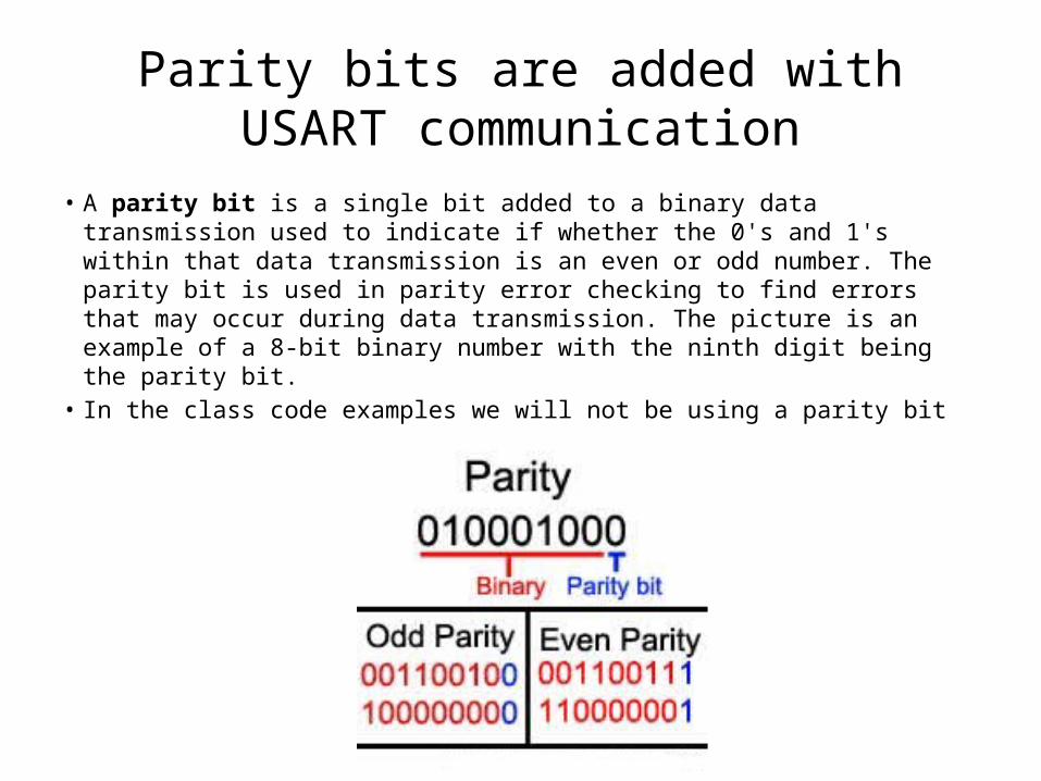
Parity bits are added with USART communication
• A parity bit is a single bit added to a binary data transmission used to indicate if whether the 0's and 1's within that data transmission is an even or odd number. The parity bit is used in parity error checking to find errors that may occur during data transmission. The picture is an example of a 8-bit binary number with the ninth digit being the parity bit.
• In the class code examples we will not be using a parity bit
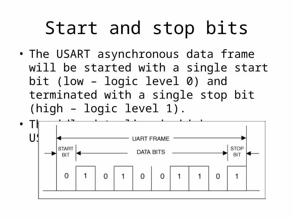
Start and stop bits• The USART asynchronous data frame will be started
with a single start bit (low – logic level 0) and terminated with a single stop bit (high – logic level 1).
• The idle data line is high on a USART
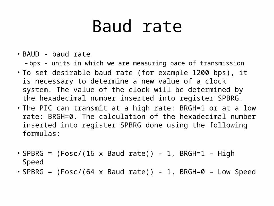
Baud rate• BAUD - baud rate
– bps - units in which we are measuring pace of transmission• To set desirable baud rate (for example 1200 bps), it is necessary
to determine a new value of a clock system. The value of the clock will be determined by the hexadecimal number inserted into register SPBRG.
• The PIC can transmit at a high rate: BRGH=1 or at a low rate: BRGH=0. The calculation of the hexadecimal number inserted into register SPBRG done using the following formulas:
• SPBRG = (Fosc/(16 x Baud rate)) - 1, BRGH=1 – High Speed• SPBRG = (Fosc/(64 x Baud rate)) - 1, BRGH=0 – Low Speed
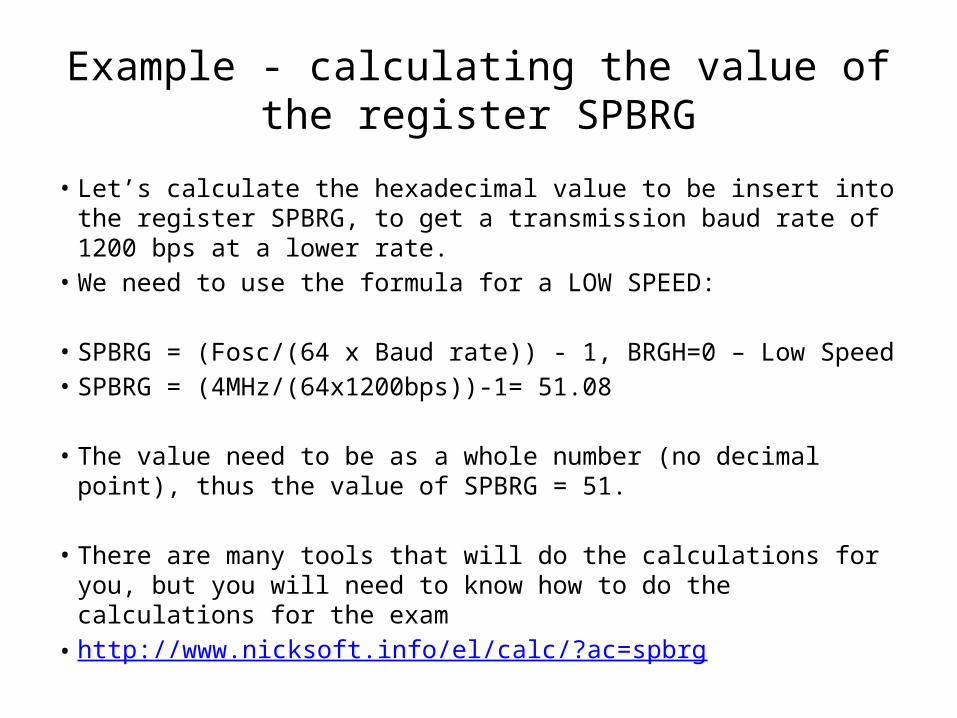
Example - calculating the value ofthe register SPBRG
• Let’s calculate the hexadecimal value to be insert into the register SPBRG, to get a transmission baud rate of 1200 bps at a lower rate.
• We need to use the formula for a LOW SPEED:
• SPBRG = (Fosc/(64 x Baud rate)) - 1, BRGH=0 – Low Speed• SPBRG = (4MHz/(64x1200bps))-1= 51.08
• The value need to be as a whole number (no decimal point), thus the value of SPBRG = 51.
• There are many tools that will do the calculations for you, but you will need to know how to do the calculations for the exam
• http://www.nicksoft.info/el/calc/?ac=spbrg
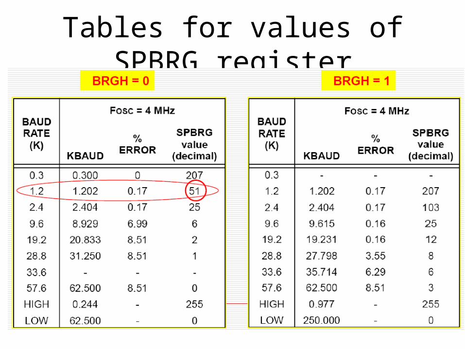
Tables for values of SPBRG register
Characteristics of USART andRSR232
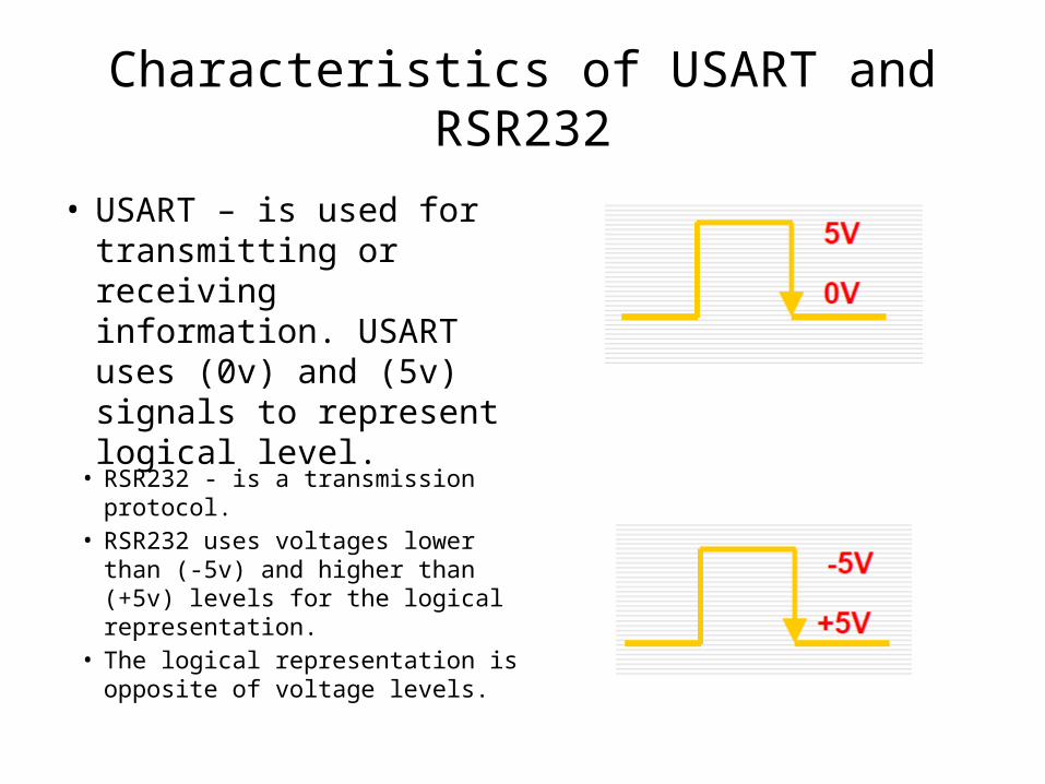
• USART – is used for transmitting or receiving information. USART uses (0v) and (5v) signals to represent logical level.
• RSR232 - is a transmission protocol.
• RSR232 uses voltages lower than (-5v) and higher than (+5v) levels for the logical representation.
• The logical representation is opposite of voltage levels.
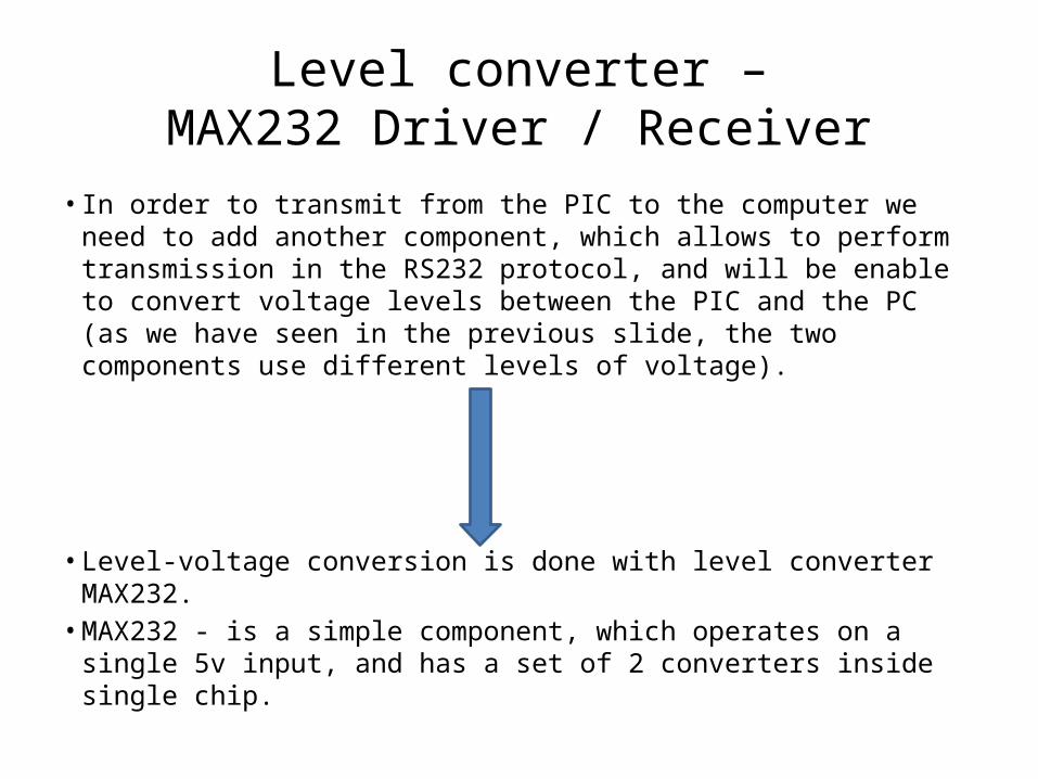
Level converter –MAX232 Driver / Receiver
• In order to transmit from the PIC to the computer we need to add another component, which allows to perform transmission in the RS232 protocol, and will be enable to convert voltage levels between the PIC and the PC (as we have seen in the previous slide, the two components use different levels of voltage).
• Level-voltage conversion is done with level converter MAX232.• MAX232 - is a simple component, which operates on a single 5v
input, and has a set of 2 converters inside single chip.
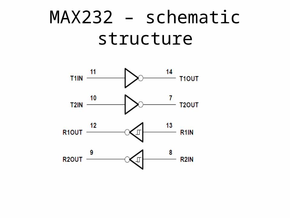
MAX232 – schematic structure
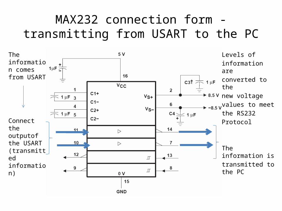
MAX232 connection form -transmitting from USART to the PC
The information comes from USART
Connect the outputof the USART (transmitted information)
Levels ofinformation areconverted to thenew voltagevalues to meetthe RS232Protocol
The information istransmitted to the PC
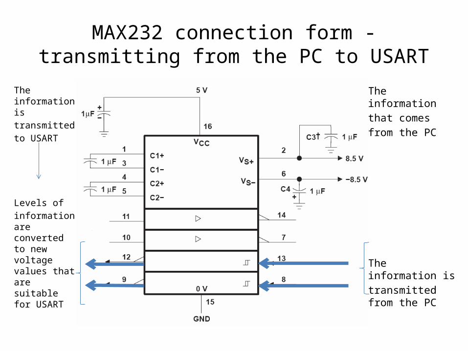
MAX232 connection form -transmitting from the PC to USART
The information istransmittedto USART
Levels ofinformation are converted to new voltage values that are suitable for USART
The informationthat comesfrom the PC
The information istransmitted from the PC
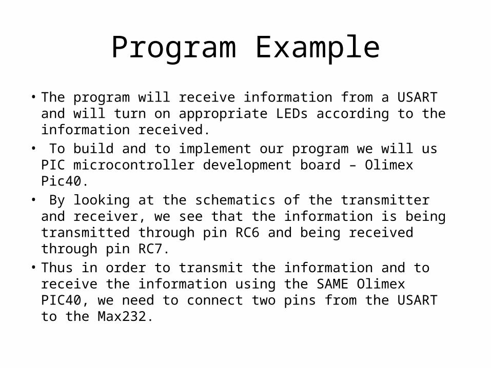
Program Example
• The program will receive information from a USART and will turn on appropriate LEDs according to the information received.
• To build and to implement our program we will us PIC microcontroller development board – Olimex Pic40.
• By looking at the schematics of the transmitter and receiver, we see that the information is being transmitted through pin RC6 and being received through pin RC7.
• Thus in order to transmit the information and to receive the information using the SAME Olimex PIC40, we need to connect two pins from the USART to the Max232.
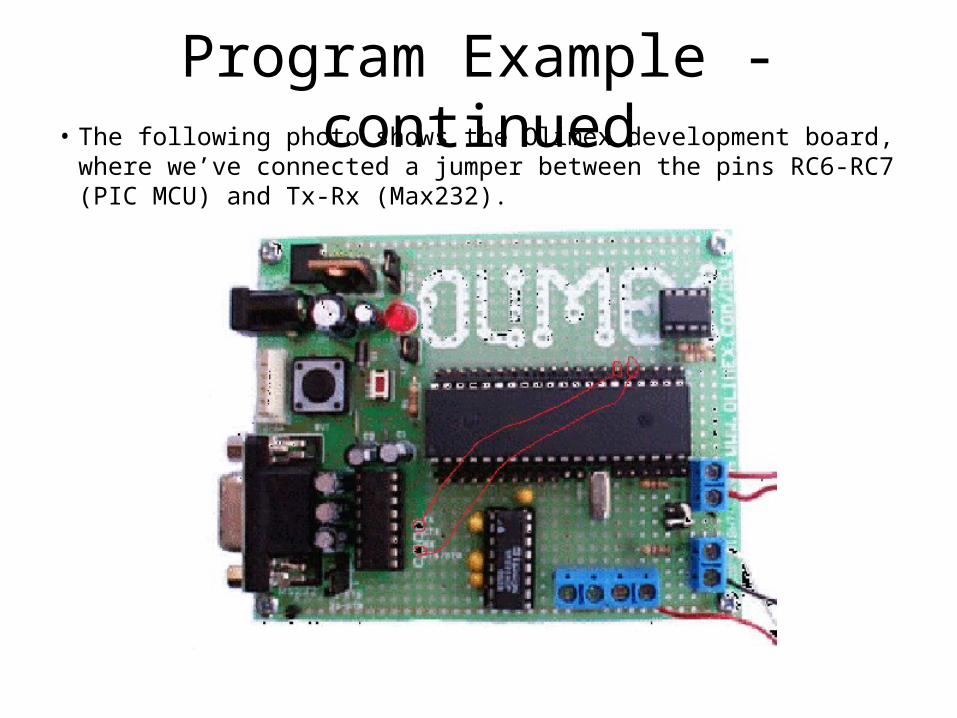
Program Example - continued• The following photo shows the Olimex development board, where we’ve
connected a jumper between the pins RC6-RC7 (PIC MCU) and Tx-Rx (Max232).
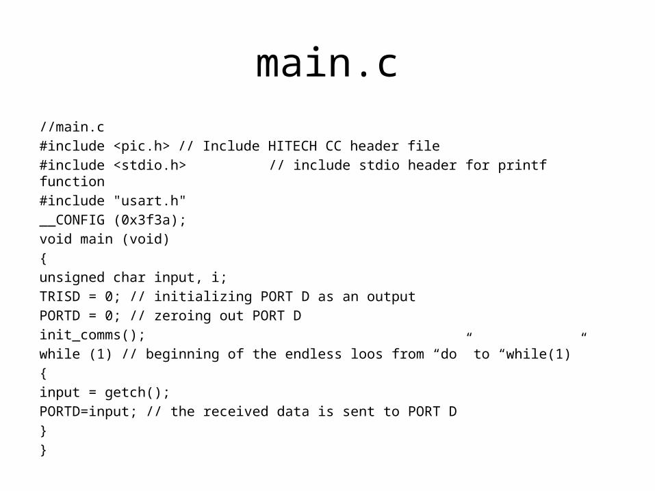
main.c//main.c#include <pic.h> // Include HITECH CC header file#include <stdio.h> // include stdio header for printf function#include "usart.h"__CONFIG (0x3f3a);void main (void){unsigned char input, i;TRISD = 0; // initializing PORT D as an outputPORTD = 0; // zeroing out PORT Dinit_comms();while (1) // beginning of the endless loos from “do” to “while(1)”{input = getch();PORTD=input; // the received data is sent to PORT D}}
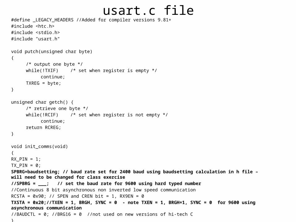
usart.c file#define _LEGACY_HEADERS //Added for compiler versions 9.81+#include <htc.h>#include <stdio.h>#include "usart.h"
void putch(unsigned char byte) {
/* output one byte */while(!TXIF) /* set when register is empty */
continue;TXREG = byte;
}
unsigned char getch() {/* retrieve one byte */while(!RCIF) /* set when register is not empty */
continue;return RCREG;
}
void init_comms(void){RX_PIN = 1;TX_PIN = 0; SPBRG=baudsetting; // baud rate set for 2400 baud using baudsetting calculation in h file – will need to be changed for class exercise//SPBRG = ___; // set the baud rate for 9600 using hard typed number//Continuous 8 bit asynchronous non inverted low speed communicationRCSTA = 0x90; // SPEN and CREN bit = 1, RX9EN = 0TXSTA = 0x20;//TXEN = 1, BRGH, SYNC = 0 - note TXEN = 1, BRGH=1, SYNC = 0 for 9600 using asynchronous communication//BAUDCTL = 0; //BRG16 = 0 //not used on new versions of hi-tech C}
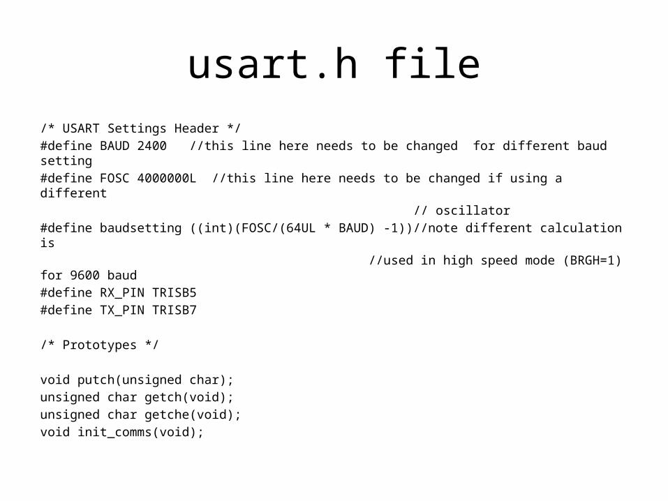
usart.h file/* USART Settings Header */#define BAUD 2400 //this line here needs to be changed for different baud setting#define FOSC 4000000L //this line here needs to be changed if using a different // oscillator#define baudsetting ((int)(FOSC/(64UL * BAUD) -1))//note different calculation is //used in high speed mode (BRGH=1) for 9600 baud#define RX_PIN TRISB5#define TX_PIN TRISB7
/* Prototypes */
void putch(unsigned char);unsigned char getch(void);unsigned char getche(void);void init_comms(void);
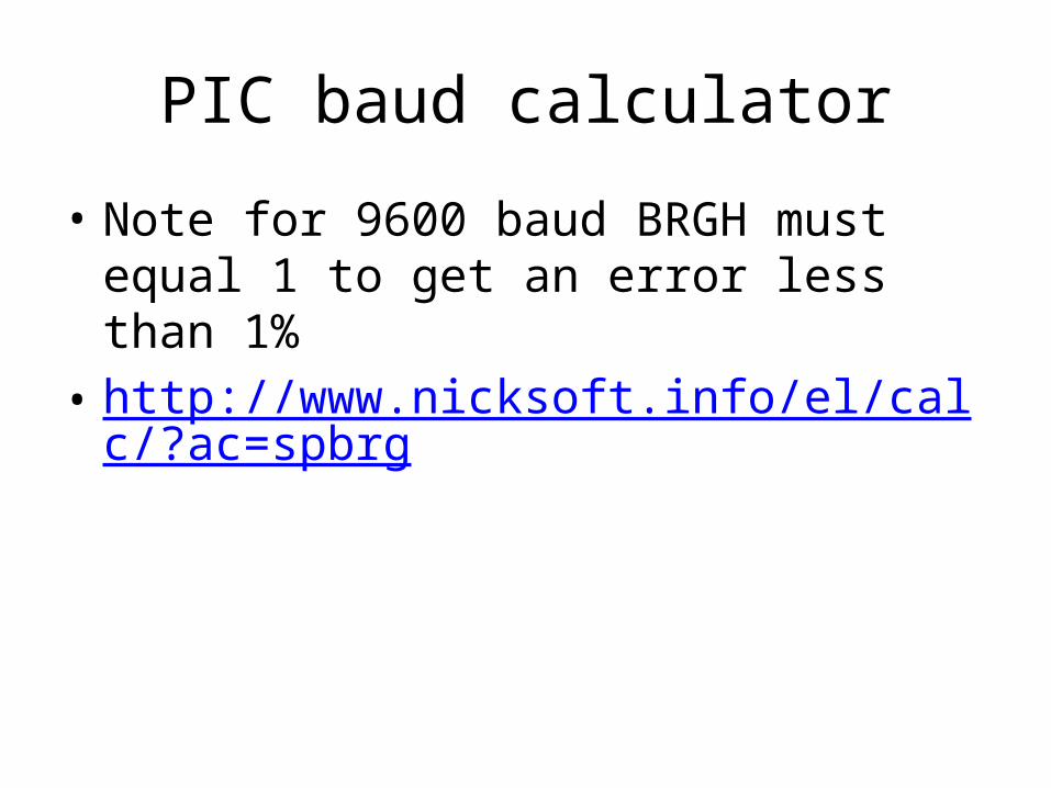
PIC baud calculator
• Note for 9600 baud BRGH must equal 1 to get an error less than 1%
• http://www.nicksoft.info/el/calc/?ac=spbrg