Embed Size (px)
Citation preview
Serial Communication Buses: I2C and SPI
By Brody Dunn
Goals
Revisit Readings of I2C and SPI Not Insult You Realize Level of Understanding Take Next Step
Implementation
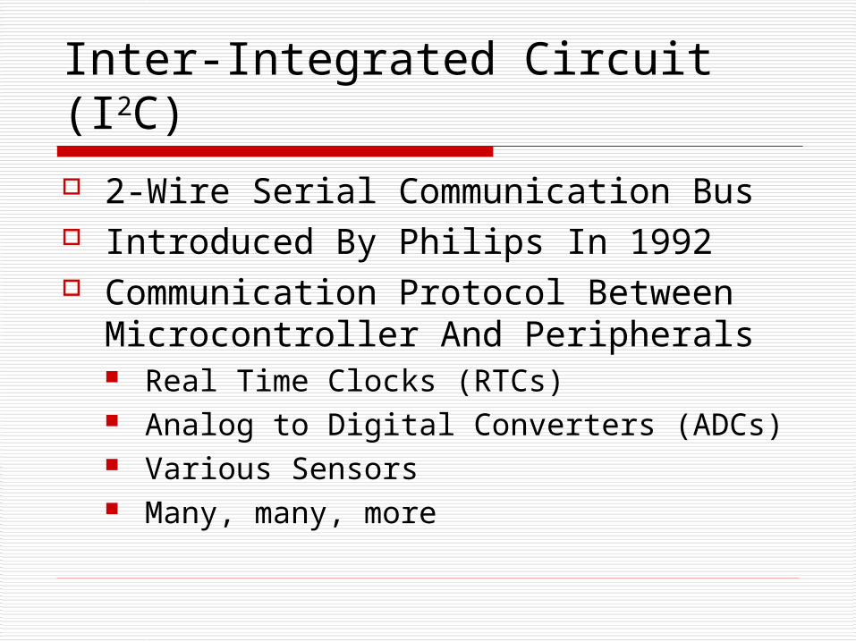
Inter-Integrated Circuit (I2C)
2-Wire Serial Communication Bus Introduced By Philips In 1992 Communication Protocol Between
Microcontroller And Peripherals Real Time Clocks (RTCs) Analog to Digital Converters (ADCs) Various Sensors Many, many, more
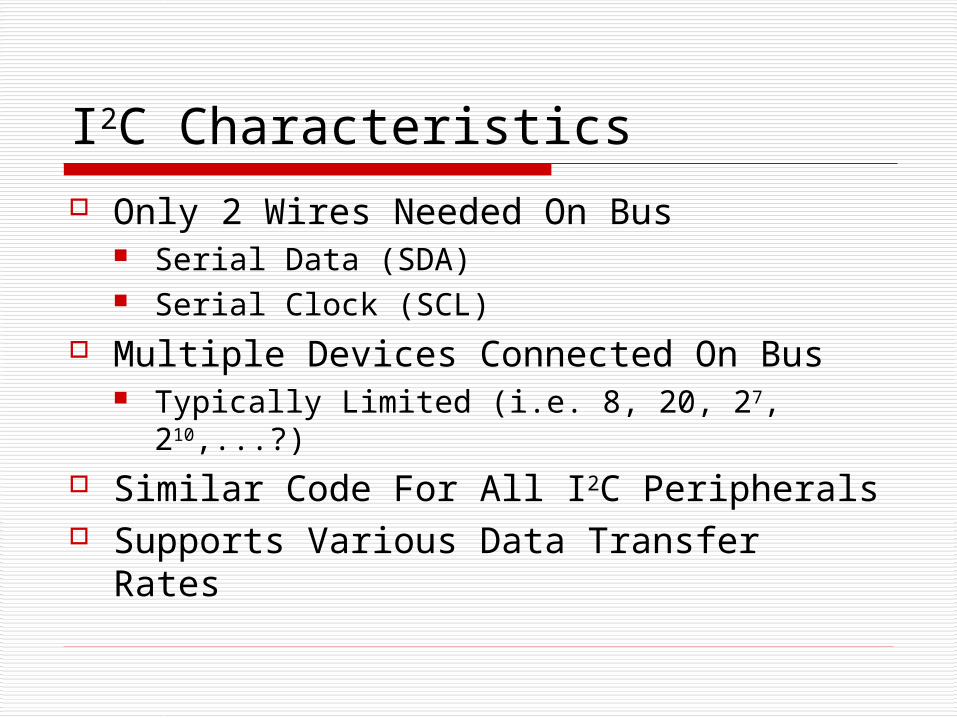
I2C Characteristics
Only 2 Wires Needed On Bus Serial Data (SDA) Serial Clock (SCL)
Multiple Devices Connected On Bus Typically Limited (i.e. 8, 20, 27, 210,...?)
Similar Code For All I2C Peripherals Supports Various Data Transfer Rates
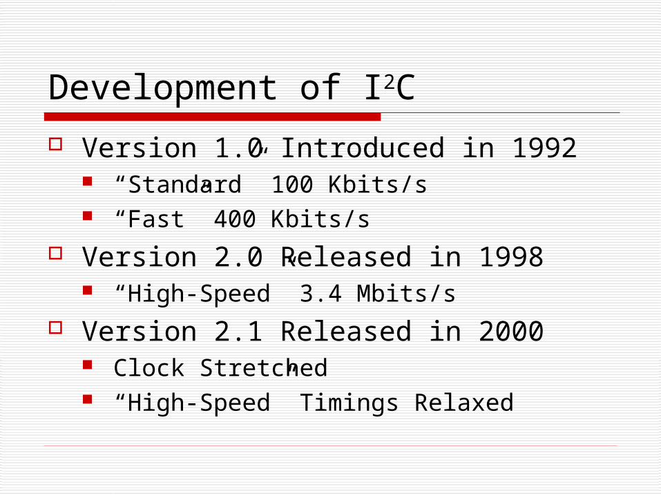
Development of I2C
Version 1.0 Introduced in 1992 “Standard” 100 Kbits/s “Fast” 400 Kbits/s
Version 2.0 Released in 1998 “High-Speed” 3.4 Mbits/s
Version 2.1 Released in 2000 Clock Stretched “High-Speed” Timings Relaxed
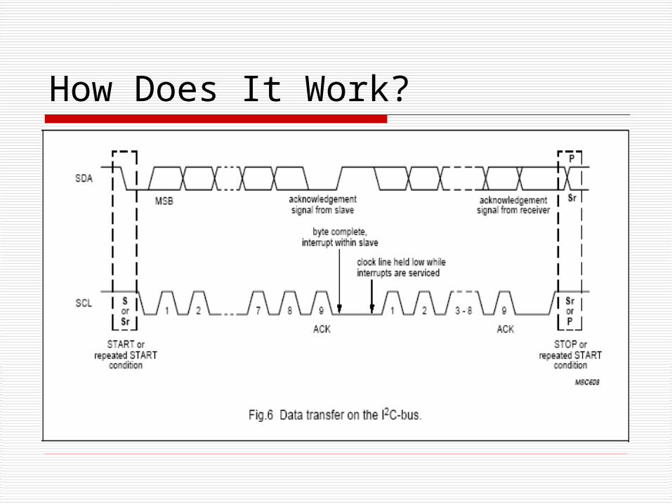
How Does It Work?
Further Reading
I2C-Bus Specification Version 2.1 http://www.semiconductors.philips.com/acrobat_download/literature/9398/39340011.pdf
DS1631 Datasheet http://pdfserv.maxim-ic.com/en/ds/DS1631-DS1731.pdf
Serial Peripheral Interface (SPI)
Synchronous Communication Protocol 3-Wire (Plus 1 Chip-Select Pin/Device) Hardware On Microcontroller
Developed By Motorola “Loose” Standard
Broad Range of Devices Supported Memory (i.e. EEPROM, RAM, Etc.) Sensors
SPI Characteristics
3 Wires (Plus Chip Select Pin/Device) Master Out Slave In (MOSI) Master In Slave Out (MISO) Master/Slave Clock Output/Input (SCK) Chip/Slave Select (SS)
Multiple Devices Connected On Bus Limited Only By Number Of uC Pins
Supports Various Data Transfer Rates
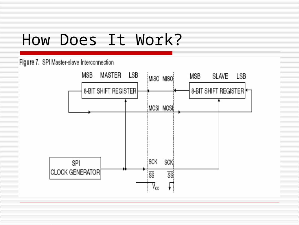
How Does It Work?
Configurations (AT89S53)
SPI Control Register (SPCR) Sets Modes of Operation
SPI Status Register (SPSR) Checks Flags
SPI Data Register (SPDR) 8-Bit Shift Register Storing Data
4 Modes of SPI
Set In SPI Control Register (SPCR) Clock Polarity
Active Low Active High
Clock Phase Data Shifted On Rising Edge Data Shifted On Falling Edge
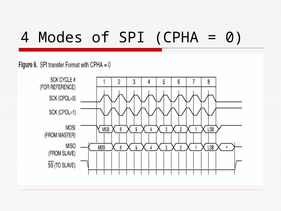
4 Modes of SPI (CPHA = 0)
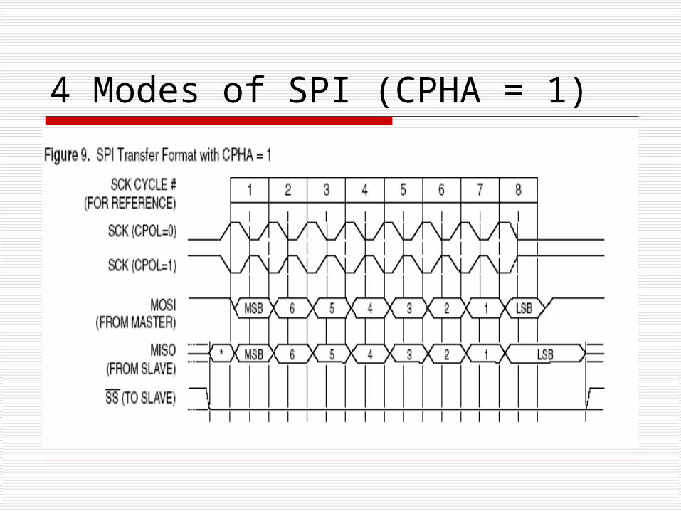
4 Modes of SPI (CPHA = 1)
Further Reading
AT89S53 Datasheet (Pg. 8, 14-16) http://www.atmel.com/dyn/resources/prod_documents/DOC0787.PDF
Pont Ch. 24
SPI Summary
3-Wire (+ SS/Device) 1.5 MHz Bit Frequency (AT89S53) Microcontroller Hardware Supports Many Devices