Embed Size (px)
Citation preview
Serial Command Guide For
WizFi630 Users (Version 1.0)
©2012 WIZnet Co., Ltd. All Rights Reserved.
☞ For more information, visit our website at http://www.wiznet.co.kr
This document describes usages for WizFi630 WIFI AP Module. Descriptions scope and boundary is limited as bellows
Testing environments Networks operation mode Serial operation Modem Supplied software usages Serial command definition
Table of contents
1. TEST ENVIRONMENT SETUP ......................................................................... 1
1.1 System Setup.................................................................................................................................................. 1
1.2 WizFi630’s default serial configuration. .................................................................................................. 1
1.3 PC #3 Setup.................................................................................................................................................... 1
1.4 PC #1 and PC#2 Serial Setup. .................................................................................................................... 1
2. SIMPLE SERIAL COMMAND AT SERIAL TERMINAL PROGRAM ........... 2
3. WIZSMARTSCRIPT FOR WIZFI630 ................................................................ 3
3.1 Run Program .................................................................................................................................................. 3
3.2 Get Basic......................................................................................................................................................... 4
3.3 Functions ..................................................................................................................................................... 10
3.4 Set Operation Mode ................................................................................................................................... 14
3.5 Set Serial ...................................................................................................................................................... 18
4. SERIAL COMMAND DEFINITIONS ............................................................. 20
5. ACCESSING MODULE VIA WEB BROWSER ............................................. 26
6. MORE INFORMATION ................................................................................... 27
1
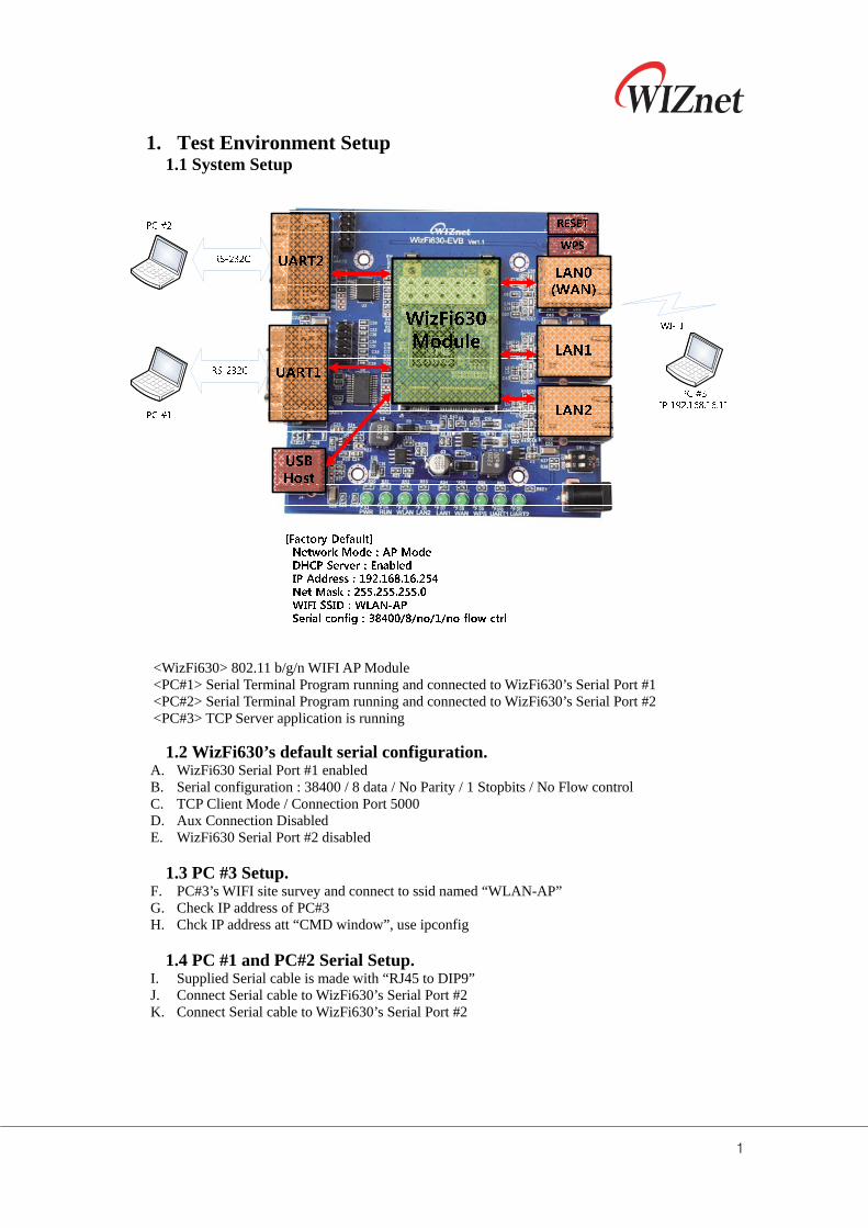
1. Test Environment Setup 1.1 System Setup
<WizFi630> 802.11 b/g/n WIFI AP Module <PC#1> Serial Terminal Program running and connected to WizFi630’s Serial Port #1 <PC#2> Serial Terminal Program running and connected to WizFi630’s Serial Port #2 <PC#3> TCP Server application is running
1.2 WizFi630’s default serial configuration. A. WizFi630 Serial Port #1 enabled B. Serial configuration : 38400 / 8 data / No Parity / 1 Stopbits / No Flow control C. TCP Client Mode / Connection Port 5000 D. Aux Connection Disabled E. WizFi630 Serial Port #2 disabled
1.3 PC #3 Setup.
F. PC#3’s WIFI site survey and connect to ssid named “WLAN-AP” G. Check IP address of PC#3 H. Chck IP address att “CMD window”, use ipconfig
1.4 PC #1 and PC#2 Serial Setup.
I. Supplied Serial cable is made with “RJ45 to DIP9” J. Connect Serial cable to WizFi630’s Serial Port #2 K. Connect Serial cable to WizFi630’s Serial Port #2

2
2. Simple serial command at serial terminal program ① <RF>
This command gets module’s firmware version and normally used to check module is working or not
② <ATDT> This command changes module’s “serial working mode” as data mode This is special command so do not type each character and <ATDT> copy and paste it at terminal program.
③ <+++> This command changes module’s serial working mode as “command mode”. In serial command, Incoming serial data is processed as serial command. In data mode, Incoming serial data is processed as data and it is sent remote network hosts. This is special command so do not type each character and <++++> copy and paste it at the terminal program..
④ <ATDT?> This command responses module’s current serial working mode. Response “1” : serial server is data mode Response “0” : serial server is command mode This is special command so do not type each character and <ATDT?> copy and paste it at terminal program.
⑤ <WP> This command set network TCP/UDP port number. As network server mode, it works as network incoming port number As network client mode, it is remote host network port number to connect server Ex) <WP5000> // Set port # as 5000
⑥ <WX> This command set remote host IP address. When set, module connect remote host automatically. Ex) <WX192.168.16.11>
⑦ <RQ> This command responses serial sever’s network connection status. 0: Not Connect 1: Connect as client 2: Connected as server 3: Connected as Client/Server
⑧ <WL> This command saves configured data to flash. When this command is processed, configed data is kept even if rebooting.
⑨ <abc11>; This is not command and it is one of sample user data for test
3
3. WIZSmartScript for WizFi630
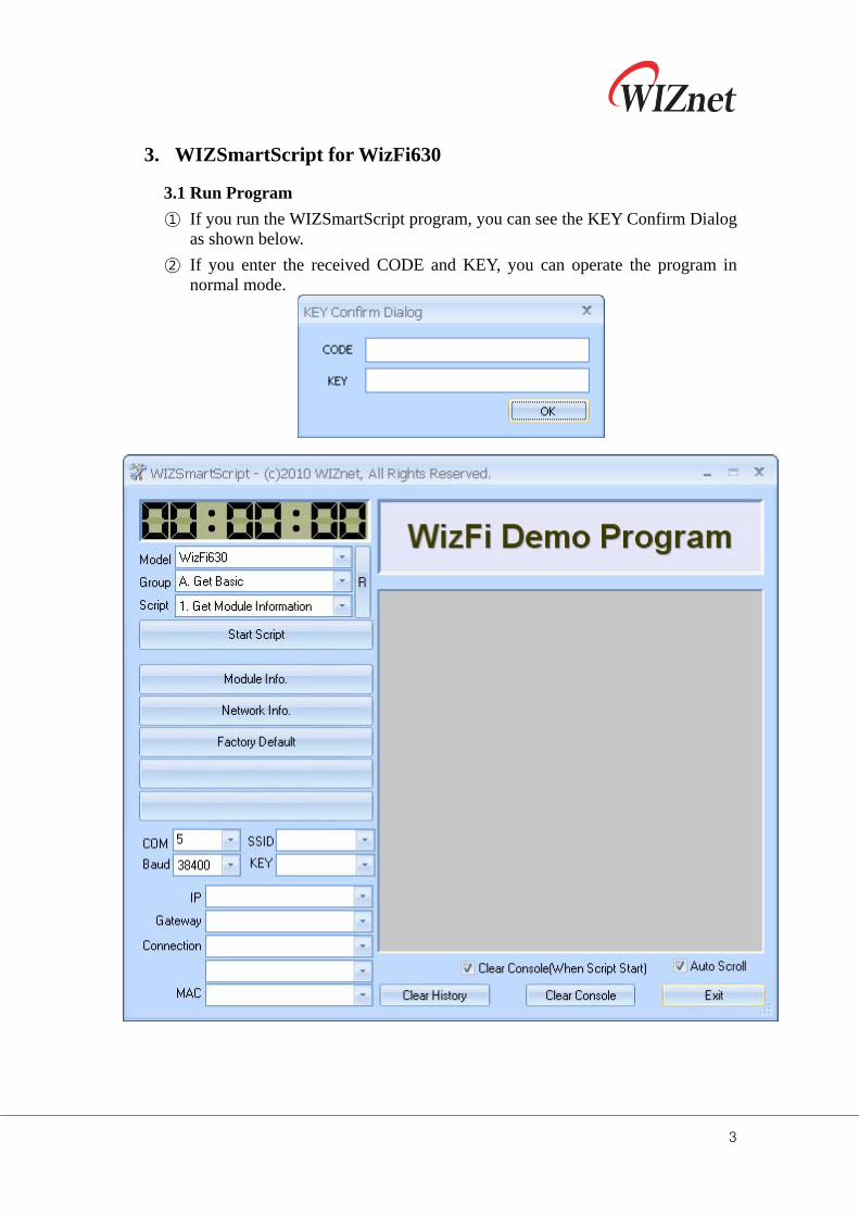
3.1 Run Program
① If you run the WIZSmartScript program, you can see the KEY Confirm Dialog as shown below.
② If you enter the received CODE and KEY, you can operate the program in normal mode.
4
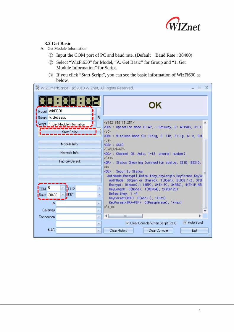
3.2 Get Basic
A. Get Module Information
① Input the COM port of PC and baud rate. (Default Baud Rate : 38400)
② Select “WizFi630” for Model, “A. Get Basic” for Group and “1. Get Module Information” for Script.
③ If you click “Start Script”, you can see the basic information of WizFi630 as below.
5
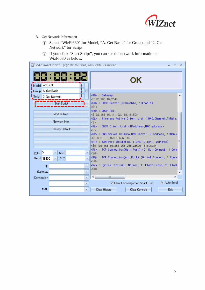
B. Get Network Information
① Select “WizFi630” for Model, “A. Get Basic” for Group and “2. Get Network” for Script.
② If you click “Start Script”, you can see the network information of WizFi630 as below.
6
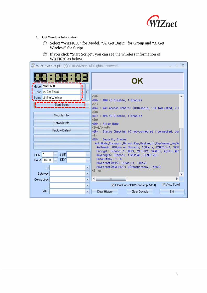
C. Get Wireless Information
① Select “WizFi630” for Model, “A. Get Basic” for Group and “3. Get Wireless” for Script.
② If you click “Start Script”, you can see the wireless information of WizFi630 as below.
7
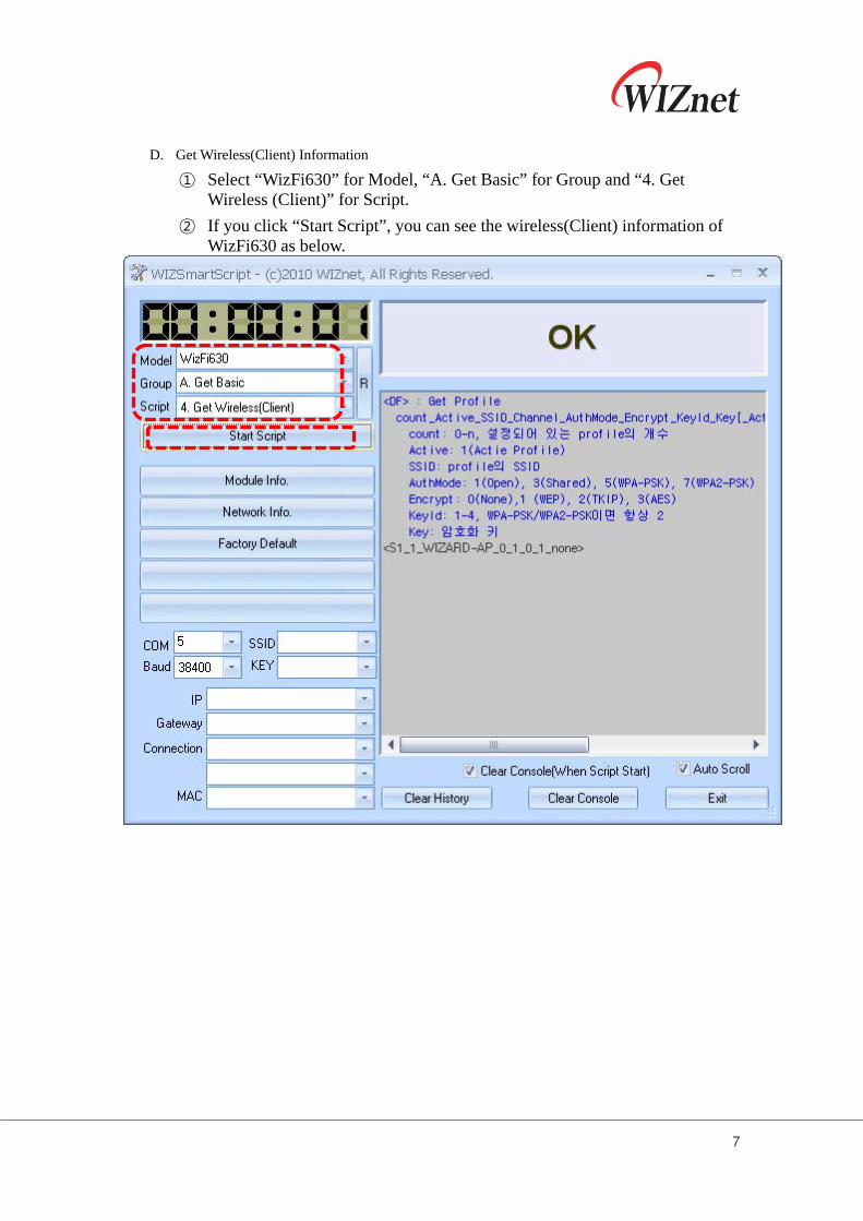
D. Get Wireless(Client) Information
① Select “WizFi630” for Model, “A. Get Basic” for Group and “4. Get Wireless (Client)” for Script.
② If you click “Start Script”, you can see the wireless(Client) information of WizFi630 as below.
8
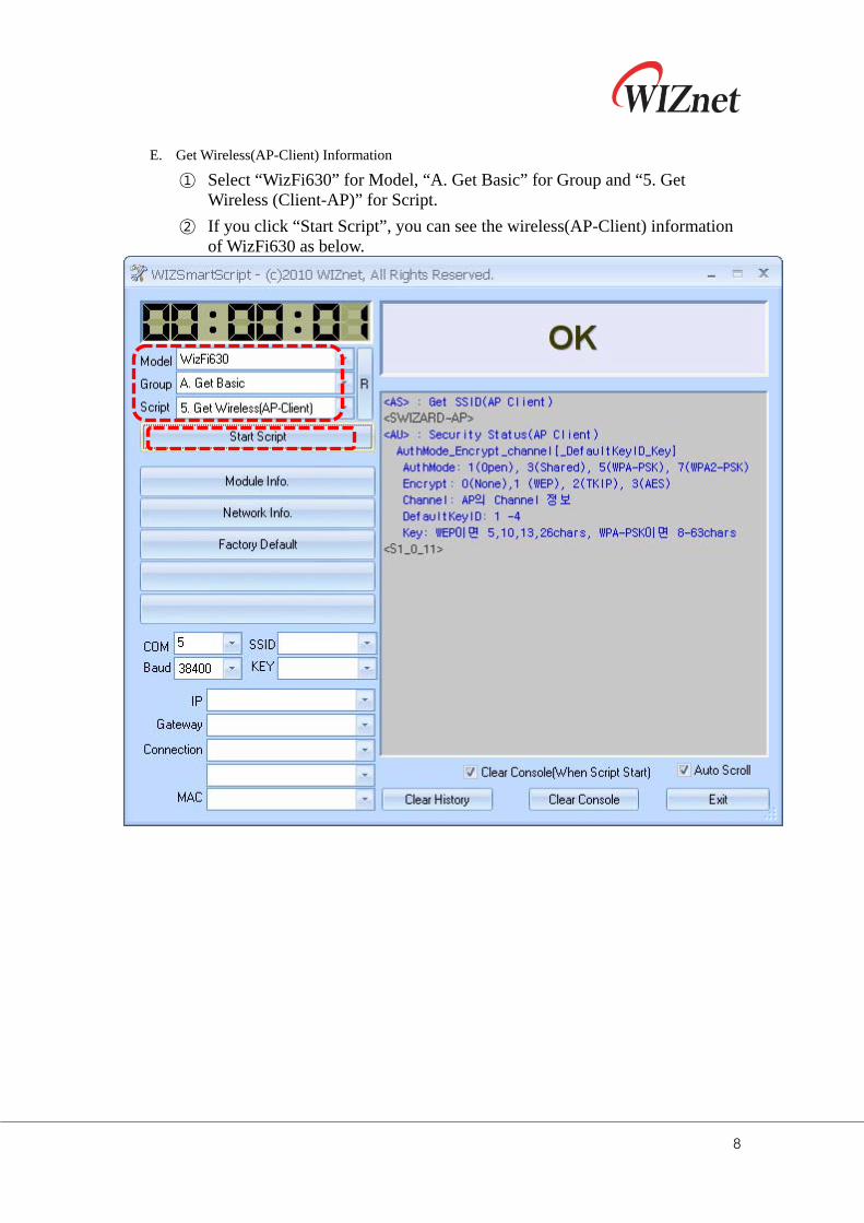
E. Get Wireless(AP-Client) Information
① Select “WizFi630” for Model, “A. Get Basic” for Group and “5. Get Wireless (Client-AP)” for Script.
② If you click “Start Script”, you can see the wireless(AP-Client) information of WizFi630 as below.
9
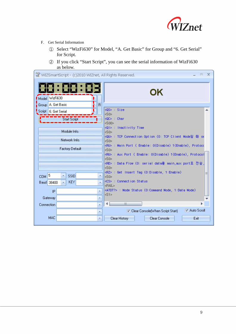
F. Get Serial Information
① Select “WizFi630” for Model, “A. Get Basic” for Group and “6. Get Serial” for Script.
② If you click “Start Script”, you can see the serial information of WizFi630 as below.
10
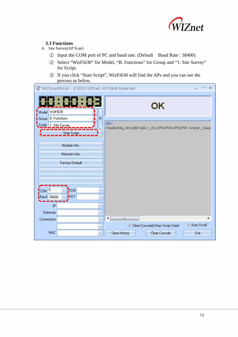
3.3 Functions
A. Site Survey(AP Scan)
① Input the COM port of PC and baud rate. (Default Baud Rate : 38400)
② Select “WizFi630” for Model, “B. Functions” for Group and “1. Site Survey” for Script.
③ If you click “Start Script”, WizFi630 will find the APs and you can see the process as below.
11
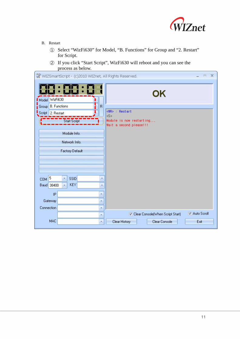
B. Restart
① Select “WizFi630” for Model, “B. Functions” for Group and “2. Restart” for Script.
② If you click “Start Script”, WizFi630 will reboot and you can see the process as below.
12
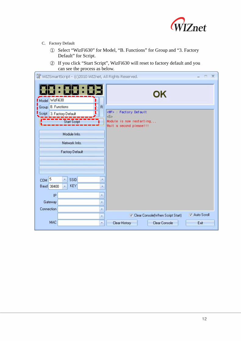
C. Factory Default
① Select “WizFi630” for Model, “B. Functions” for Group and “3. Factory Default” for Script.
② If you click “Start Script”, WizFi630 will reset to factory default and you can see the process as below.
13
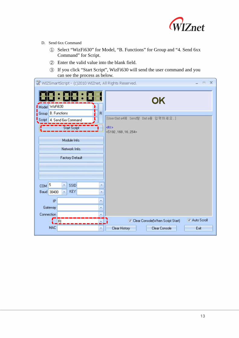
D. Send 6xx Command
① Select “WizFi630” for Model, “B. Functions” for Group and “4. Send 6xx Command” for Script.
② Enter the valid value into the blank field.
③ If you click “Start Script”, WizFi630 will send the user command and you can see the process as below.
14
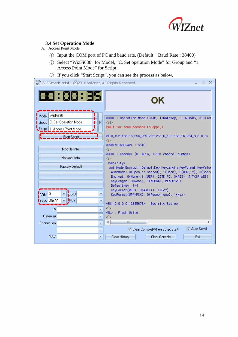
3.4 Set Operation Mode
A. Access Point Mode
① Input the COM port of PC and baud rate. (Default Baud Rate : 38400)
② Select “WizFi630” for Model, “C. Set operation Mode” for Group and “1. Access Point Mode” for Script.
③ If you click “Start Script”, you can see the process as below.
15
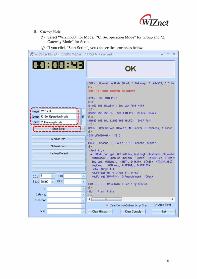
B. Gateway Mode
① Select “WizFi630” for Model, “C. Set operation Mode” for Group and “2. Gateway Mode” for Script.
② If you click “Start Script”, you can see the process as below.
16
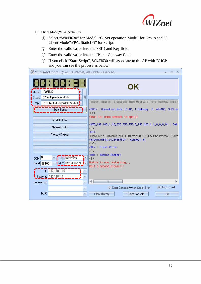
C. Client Mode(WPA, Static IP)
① Select “WizFi630” for Model, “C. Set operation Mode” for Group and “3. Client Mode(WPA, StaticIP)” for Script.
② Enter the valid value into the SSID and Key field.
③ Enter the valid value into the IP and Gateway field.
④ If you click “Start Script”, WizFi630 will associate to the AP with DHCP and you can see the process as below.
17
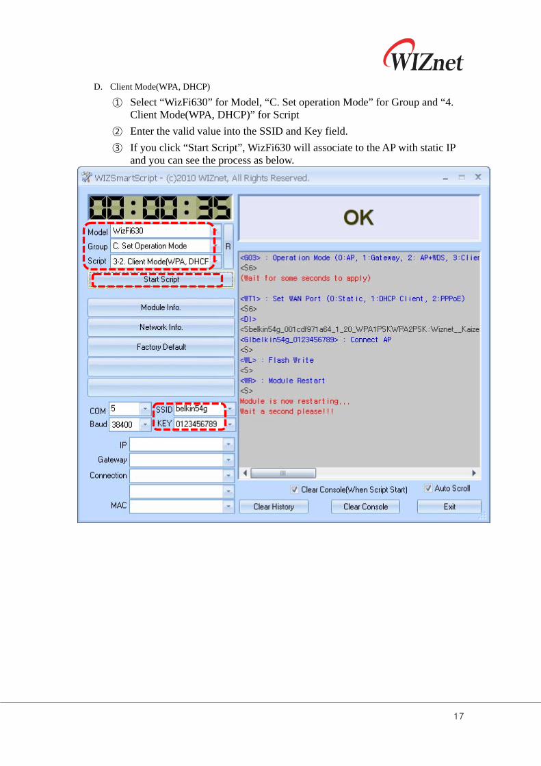
D. Client Mode(WPA, DHCP)
① Select “WizFi630” for Model, “C. Set operation Mode” for Group and “4. Client Mode(WPA, DHCP)” for Script
② Enter the valid value into the SSID and Key field.
③ If you click “Start Script”, WizFi630 will associate to the AP with static IP and you can see the process as below.
18
3.5 Set Serial
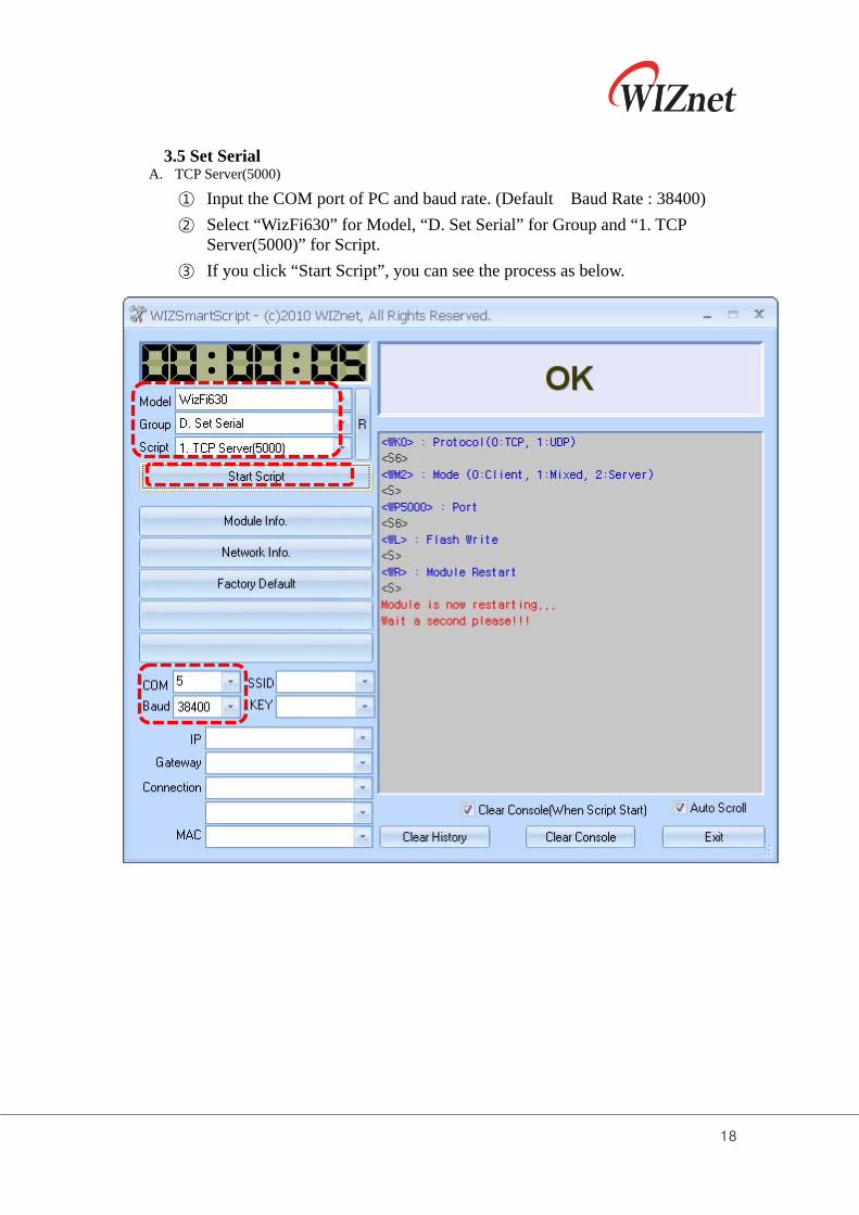
A. TCP Server(5000)
① Input the COM port of PC and baud rate. (Default Baud Rate : 38400)
② Select “WizFi630” for Model, “D. Set Serial” for Group and “1. TCP Server(5000)” for Script.
③ If you click “Start Script”, you can see the process as below.
19
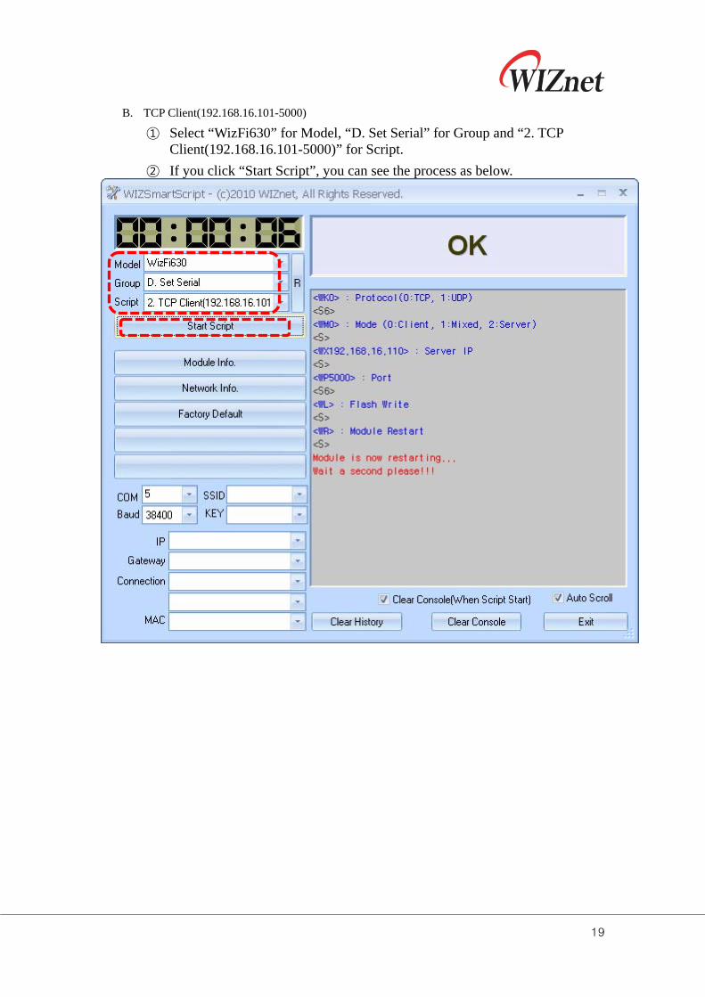
B. TCP Client(192.168.16.101-5000)
① Select “WizFi630” for Model, “D. Set Serial” for Group and “2. TCP Client(192.168.16.101-5000)” for Script.
② If you click “Start Script”, you can see the process as below.
20
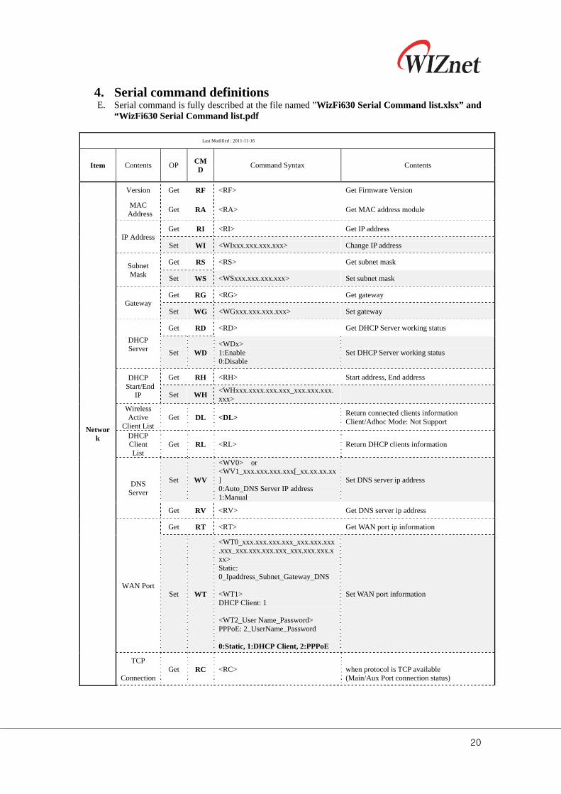
4. Serial command definitions E. Serial command is fully described at the file named ”WizFi630 Serial Command list.xlsx” and
“WizFi630 Serial Command list.pdf
Last Modified : 2011-11-16
Item Contents OP CMD
Command Syntax Contents
Network
Version Get RF <RF> Get Firmware Version
MAC Address
Get RA <RA> Get MAC address module
IP Address Get RI <RI> Get IP address
Set WI <WIxxx.xxx.xxx.xxx> Change IP address
Subnet Mask
Get RS <RS> Get subnet mask
Set WS <WSxxx.xxx.xxx.xxx> Set subnet mask
Gateway Get RG <RG> Get gateway
Set WG <WGxxx.xxx.xxx.xxx> Set gateway
DHCP Server
Get RD <RD> Get DHCP Server working status
Set WD <WDx> 1:Enable 0:Disable
Set DHCP Server working status
DHCP Start/End
IP
Get RH <RH> Start address, End address
Set WH <WHxxx.xxxx.xxx.xxx_xxx.xxx.xxx.xxx>
Wireless Active
Client List Get DL <DL>
Return connected clients information Client/Adhoc Mode: Not Support
DHCP Client List
Get RL <RL> Return DHCP clients information
DNS Server
Set WV
<WV0> or <WV1_xxx.xxx.xxx.xxx[_xx.xx.xx.xx] 0:Auto_DNS Server IP address 1:Manual
Set DNS server ip address
Get RV <RV> Get DNS server ip address
WAN Port
Get RT <RT> Get WAN port ip information
Set WT
<WT0_xxx.xxx.xxx.xxx_xxx.xxx.xxx.xxx_xxx.xxx.xxx.xxx_xxx.xxx.xxx.xxx> Static: 0_Ipaddress_Subnet_Gateway_DNS <WT1> DHCP Client: 1 <WT2_User Name_Password> PPPoE: 2_UserName_Password 0:Static, 1:DHCP Client, 2:PPPoE
Set WAN port information
TCP
Connection Get RC <RC>
when protocol is TCP available (Main/Aux Port connection status)
21
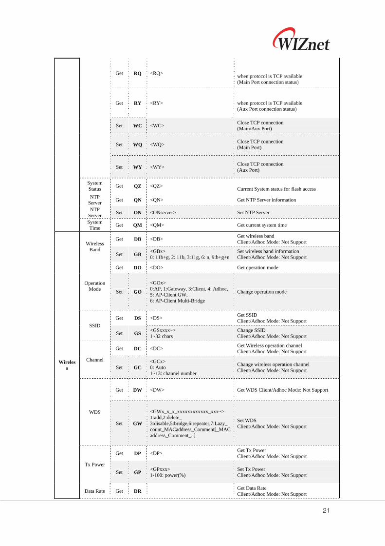
Get RQ <RQ>
when protocol is TCP available (Main Port connection status)
Get RY <RY> when protocol is TCP available (Aux Port connection status)
Set WC <WC> Close TCP connection (Main/Aux Port)
Set WQ <WQ> Close TCP connection (Main Port)
Set WY <WY> Close TCP connection (Aux Port)
System Status
Get QZ <QZ> Current System status for flash access
NTP Server
Get QN <QN> Get NTP Server information
NTP Server
Set ON <ONserver> Set NTP Server
System Time
Get QM <QM> Get current system time
Wireless
Wireless Band
Get DB <DB> Get wireless band Client/Adhoc Mode: Not Support
Set GB <GBx> 0: 11b+g, 2: 11b, 3:11g, 6: n, 9:b+g+n
Set wireless band information Client/Adhoc Mode: Not Support
Operation Mode
Get DO <DO> Get operation mode
Set GO
<GOx> 0:AP, 1:Gateway, 3:Client, 4: Adhoc, 5: AP-Client GW, 6: AP-Client Multi-Bridge
Change operation mode
SSID
Get DS <DS> Get SSID Client/Adhoc Mode: Not Support
Set GS <GSxxxx~> 1~32 chars
Change SSID Client/Adhoc Mode: Not Support
Channel
Get DC <DC> Get Wireless operation channel Client/Adhoc Mode: Not Support
Set GC <GCx> 0: Auto 1~13: channel number
Change wireless operation channel Client/Adhoc Mode: Not Support
WDS
Get DW <DW> Get WDS Client/Adhoc Mode: Not Support
Set GW
<GWx_x_x_xxxxxxxxxxxx_xxx~> 1:add,2:delete_ 3:disable,5:bridge,6:repeater,7:Lazy_ count_MACaddress_Comment[_MACaddress_Comment_..]
Set WDS Client/Adhoc Mode: Not Support
Tx Power
Get DP <DP> Get Tx Power Client/Adhoc Mode: Not Support
Set GP <GPxxx> 1-100: power(%)
Set Tx Power Client/Adhoc Mode: Not Support
Data Rate Get DR Get Data Rate Client/Adhoc Mode: Not Support
22
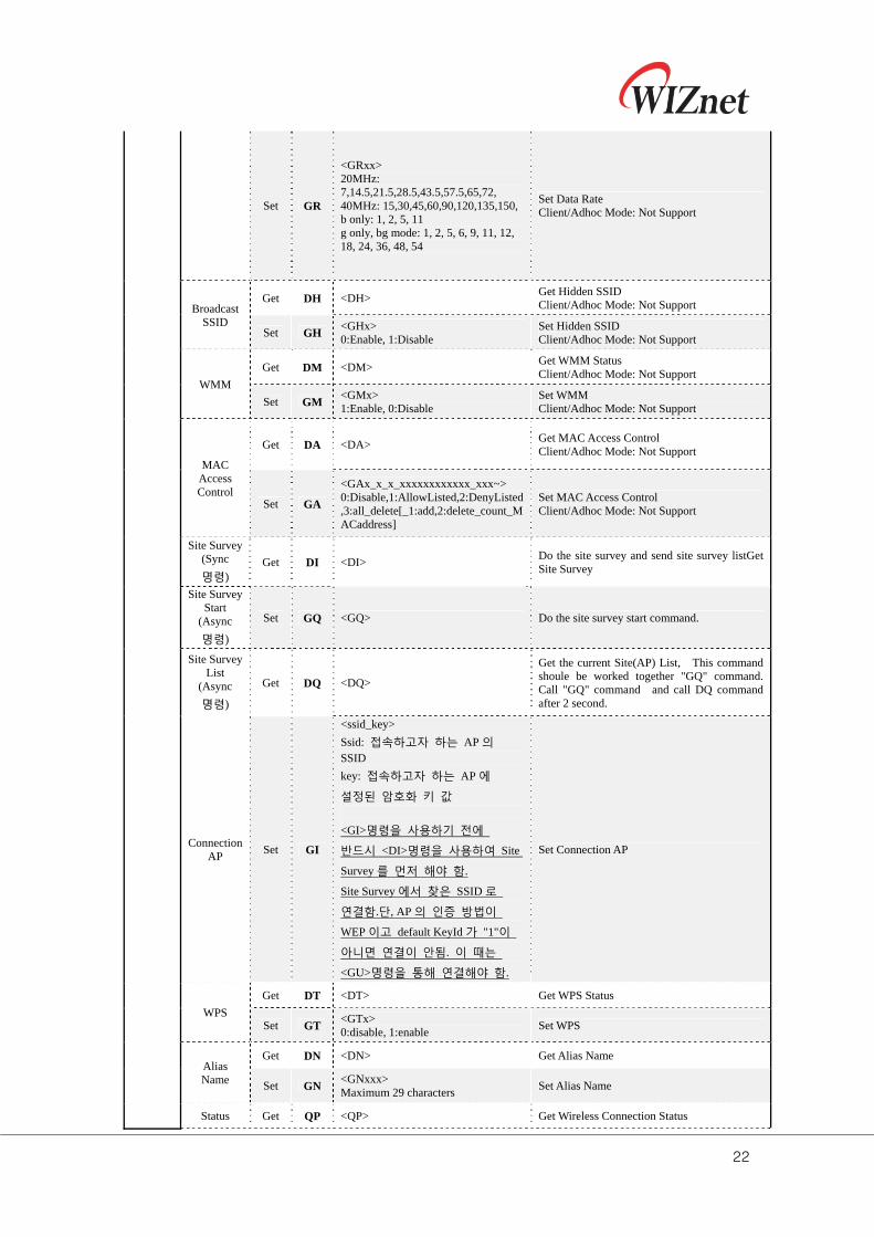
Set GR
<GRxx> 20MHz: 7,14.5,21.5,28.5,43.5,57.5,65,72, 40MHz: 15,30,45,60,90,120,135,150, b only: 1, 2, 5, 11 g only, bg mode: 1, 2, 5, 6, 9, 11, 12, 18, 24, 36, 48, 54
Set Data Rate Client/Adhoc Mode: Not Support
Broadcast SSID
Get DH <DH> Get Hidden SSID Client/Adhoc Mode: Not Support
Set GH <GHx> 0:Enable, 1:Disable
Set Hidden SSID Client/Adhoc Mode: Not Support
WMM
Get DM <DM> Get WMM Status Client/Adhoc Mode: Not Support
Set GM <GMx> 1:Enable, 0:Disable
Set WMM Client/Adhoc Mode: Not Support
MAC Access Control
Get DA <DA> Get MAC Access Control Client/Adhoc Mode: Not Support
Set GA
<GAx_x_x_xxxxxxxxxxxx_xxx~> 0:Disable,1:AllowListed,2:DenyListed,3:all_delete[_1:add,2:delete_count_MACaddress]
Set MAC Access Control Client/Adhoc Mode: Not Support
Site Survey (Sync
명령) Get DI <DI>
Do the site survey and send site survey listGet Site Survey
Site Survey Start
(Async
명령)
Set GQ <GQ> Do the site survey start command.
Site Survey List
(Async
명령)
Get DQ <DQ>
Get the current Site(AP) List, This command shoule be worked together "GQ" command. Call "GQ" command and call DQ command after 2 second.
Connection AP
Set GI
<ssid_key>
Ssid: 접속하고자 하는 AP 의 SSID
key: 접속하고자 하는 AP 에
설정된 암호화 키 값
<GI>명령을 사용하기 전에
반드시 <DI>명령을 사용하여 Site
Survey 를 먼저 해야 함.
Site Survey 에서 찾은 SSID 로
연결함.단, AP 의 인증 방법이
WEP 이고 default KeyId 가 "1"이
아니면 연결이 안됨. 이 때는
<GU>명령을 통해 연결해야 함.
Set Connection AP
WPS
Get DT <DT> Get WPS Status
Set GT <GTx> 0:disable, 1:enable
Set WPS
Alias Name
Get DN <DN> Get Alias Name
Set GN <GNxxx> Maximum 29 characters
Set Alias Name
Status Get QP <QP> Get Wireless Connection Status
23
Checking
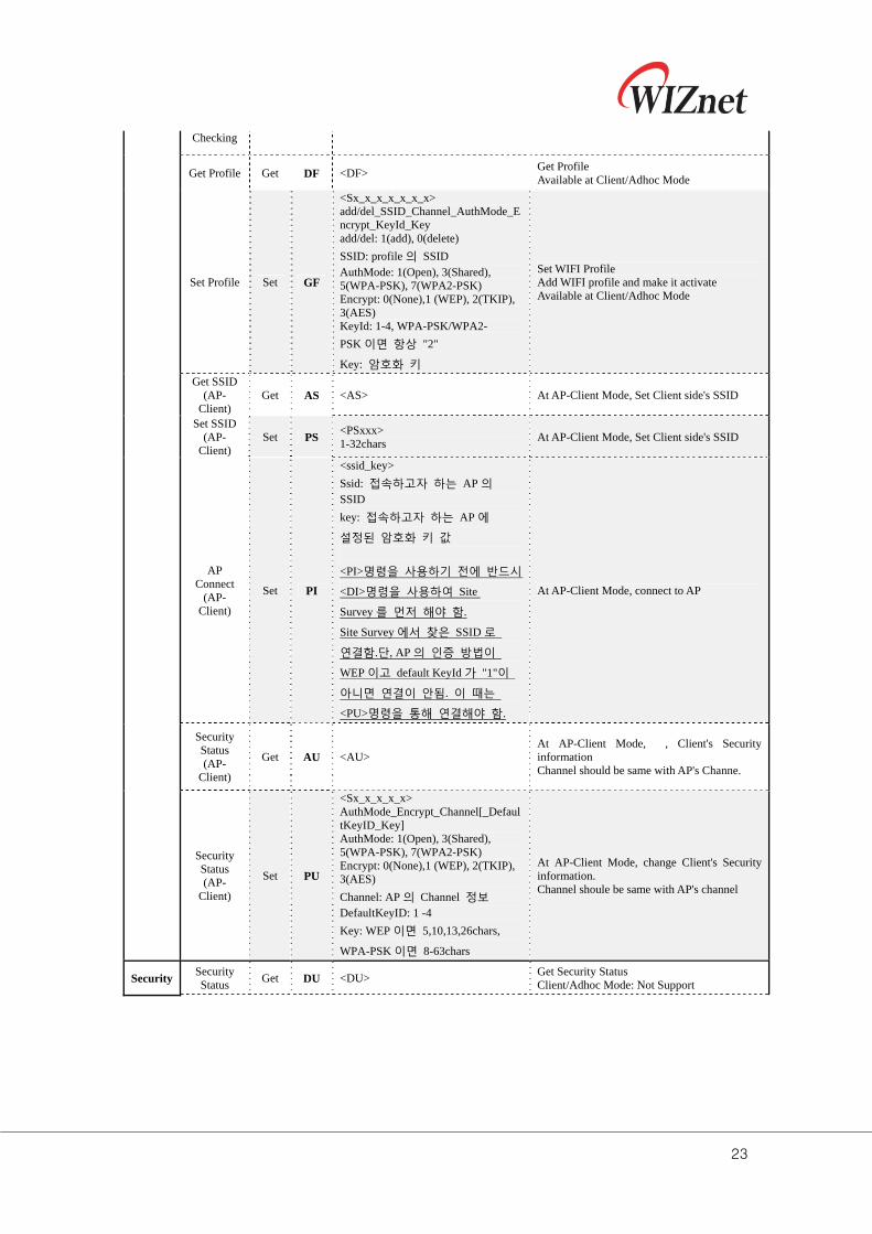
Get Profile Get DF <DF> Get Profile Available at Client/Adhoc Mode
Set Profile Set GF
<Sx_x_x_x_x_x_x> add/del_SSID_Channel_AuthMode_Encrypt_KeyId_Key add/del: 1(add), 0(delete)
SSID: profile 의 SSID AuthMode: 1(Open), 3(Shared), 5(WPA-PSK), 7(WPA2-PSK) Encrypt: 0(None),1 (WEP), 2(TKIP), 3(AES) KeyId: 1-4, WPA-PSK/WPA2-
PSK 이면 항상 "2"
Key: 암호화 키
Set WIFI Profile Add WIFI profile and make it activate Available at Client/Adhoc Mode
Get SSID (AP-
Client) Get AS <AS> At AP-Client Mode, Set Client side's SSID
Set SSID (AP-
Client) Set PS
<PSxxx> 1-32chars
At AP-Client Mode, Set Client side's SSID
AP Connect
(AP-Client)
Set PI
<ssid_key>
Ssid: 접속하고자 하는 AP 의 SSID
key: 접속하고자 하는 AP 에
설정된 암호화 키 값
<PI>명령을 사용하기 전에 반드시
<DI>명령을 사용하여 Site
Survey 를 먼저 해야 함.
Site Survey 에서 찾은 SSID 로
연결함.단, AP 의 인증 방법이
WEP 이고 default KeyId 가 "1"이
아니면 연결이 안됨. 이 때는
<PU>명령을 통해 연결해야 함.
At AP-Client Mode, connect to AP
Security Status (AP-
Client)
Get AU <AU> At AP-Client Mode, , Client's Security information Channel should be same with AP's Channe.
Security Status (AP-
Client)
Set PU
<Sx_x_x_x_x> AuthMode_Encrypt_Channel[_DefaultKeyID_Key] AuthMode: 1(Open), 3(Shared), 5(WPA-PSK), 7(WPA2-PSK) Encrypt: 0(None),1 (WEP), 2(TKIP), 3(AES)
Channel: AP 의 Channel 정보 DefaultKeyID: 1 -4
Key: WEP 이면 5,10,13,26chars,
WPA-PSK 이면 8-63chars
At AP-Client Mode, change Client's Security information. Channel shoule be same with AP's channel
Security Security Status
Get DU <DU> Get Security Status Client/Adhoc Mode: Not Support
24
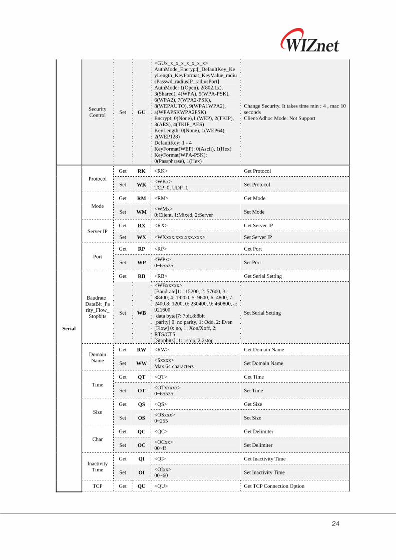
Security Control
Set GU
<GUx_x_x_x_x_x_x_x> AuthMode_Encrypt[_DefaultKey_KeyLength_KeyFormat_KeyValue_radiusPasswd_radiusIP_radiusPort] AuthMode: 1(Open), 2(802.1x), 3(Shared), 4(WPA), 5(WPA-PSK), 6(WPA2), 7(WPA2-PSK), 8(WEPAUTO), 9(WPA1WPA2), a(WPAPSKWPA2PSK) Encrypt: 0(None),1 (WEP), 2(TKIP), 3(AES), 4(TKIP_AES) KeyLength: 0(None), 1(WEP64), 2(WEP128) DefaultKey: 1 - 4 KeyFormat(WEP): 0(Ascii), 1(Hex) KeyFormat(WPA-PSK): 0(Passphrase), 1(Hex)
Change Security. It takes time min : 4 , mac 10 seconds Client/Adhoc Mode: Not Support
Serial
Protocol
Get RK <RK> Get Protocol
Set WK <WKx> TCP_0, UDP_1
Set Protocol
Mode
Get RM <RM> Get Mode
Set WM <WMx> 0:Client, 1:Mixed, 2:Server
Set Mode
Server IP Get RX <RX> Get Server IP
Set WX <WXxxx.xxx.xxx.xxx> Set Server IP
Port
Get RP <RP> Get Port
Set WP <WPx> 0~65535
Set Port
Baudrate_DataBit_Parity_Flow_
Stopbits
Get RB <RB> Get Serial Setting
Set WB
<WBxxxxx> [Baudrate]1: 115200, 2: 57600, 3: 38400, 4: 19200, 5: 9600, 6: 4800, 7: 2400,8: 1200, 0: 230400, 9: 460800, a: 921600 [data byte]7: 7bit,8:8bit [parity] 0: no parity, 1: Odd, 2: Even [Flow] 0: no, 1: Xon/Xoff, 2: RTS/CTS [Stopbits]; 1: 1stop, 2:2stop
Set Serial Setting
Domain Name
Get RW <RW> Get Domain Name
Set WW <Sxxxx> Max 64 characters
Set Domain Name
Time
Get QT <QT> Get Time
Set OT <OTxxxxx> 0~65535
Set Time
Size
Get QS <QS> Get Size
Set OS <OSxxx> 0~255
Set Size
Char
Get QC <QC> Get Delimiter
Set OC <OCxx> 00~ff
Set Delimiter
Inactivity Time
Get QI <QI> Get Inactivity Time
Set OI <OIxx> 00~60
Set Inactivity Time
TCP Get QU <QU> Get TCP Connection Option
25
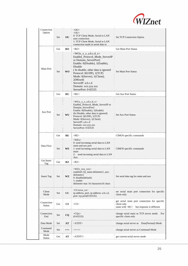
Connection Option
Set OU
<OU> <OU> 0: TCP Client Mode, Serial to LAN auto connection 1: TCP Client Mode, Serial to LAN connection made in serial date in
Set TCP Connection Option
Main Port
Get RO <RO> Get Main Port Status
Set WO
<WOx_x_x_a.b.c.d_x> Enable[_Protocol_Mode_ServerIP or Domain_ServerPort] Enable: 0(Disable), 1(Enable), Disable ( In disable, other data is ignored Protocol: 0(UDP), 1(TCP) Mode: 0(Server), 1(Client), 2(Mixed) ServerIP: a.b.c.d Domain: xxx.yyy.zzz ServerPort: 0-65535
Set Main Port Status
Aux Port
Get RU <RU> Get Aux Port Status
Set WU
<WUx_x_x_a.b.c.d_x> Enable[_Protocol_Mode_ServerIP or Domain_ServerPort] Enable: 0(Disable), 1(Enable) (In Disable, other data is ignored) Protocol: 0(UDP), 1(TCP) Mode: 0(Server), 1(Client) ServerIP: a.b.c.d Domain: xxx.yyy.zzz ServerPort: 0-65535
Set Aux Port Status
Data Flow
Get RE <RE> CIMOS specific commands
Set WE
<WEx> 0: send incoming serial data to LAN main and aux port 1: send incoming serial data to LAN main 2: send incoming serial data to LAN Aux
CIMOS specific commands
Get Insert Tag
Get RZ <RZ>
Insert Tag Set WZ
<WZx_xxx_xxx> enable(0-1)[_main-delimeter1_aux-delimeter] 0: disable(default) 1: enable delimeter mac 16 characters16 chars
Set seral data tag for main and aux
Client Mode
Set CC <CCxxxx_xx> ip-address_port, ip-address: a.b.c.d, port: tcp port(0-65535)
set serial main port connection for specific client only
Connection Status
Get CS <CS> get serial main port connection for specific client only same with <RC> but response is different
Connection End
Set CQ <CQx> (0-65535)
change serial main as TCP server mode. For specific client only
Data Mode Set AT <ATDT> change serial server as Data(Normal) Mode
Command Mode
Set +++ <+++> change serial server as Command Mode
Mode Status
Get AT <ATDT?> get current serial server mode
26
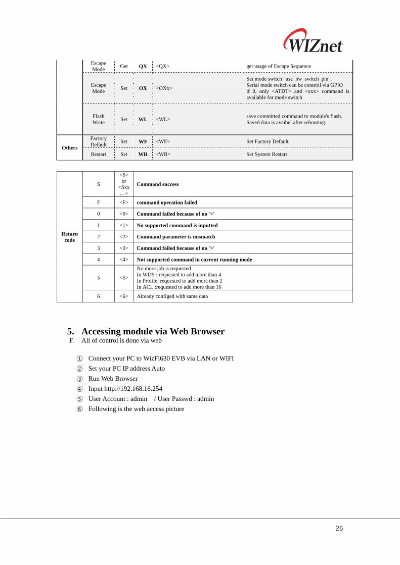
Escape Mode
Get QX <QX> get usage of Escape Sequence
Escape Mode
Set OX <OXx>
Set mode switch "use_hw_switch_pin". Serial mode switch can be controll via GPIO if 0, only <ATDT> and <xxx> command is available for mode switch
Flash Write
Set WL <WL> save committed command to module's flash. Saved data is avaibel after rebooting.
Others
Factory Default
Set WF <WF> Set Factory Default
Restart Set WR <WR> Set System Restart
Return code
S
<S> or
<Sxx…>
Command success
F <F> command operation failed
0 <0> Command failed because of no '<'
1 <1> No supported command is inputted
2 <2> Command parameter is mismatch
3 <3> Command failed because of no '>'
4 <4> Not supported command in current running mode
5 <5>
No more job is requested In WDS : requested to add more than 4 In Profile: requested to add more than 2 In ACL :requested to add more than 16
6 <6> Already configed with same data
5. Accessing module via Web Browser F. All of control is done via web
① Connect your PC to WizFi630 EVB via LAN or WIFI
② Set your PC IP address Auto
③ Run Web Browser
④ Input http://192.168.16.254
⑤ User Account : admin / User Passwd : admin
⑥ Following is the web access picture
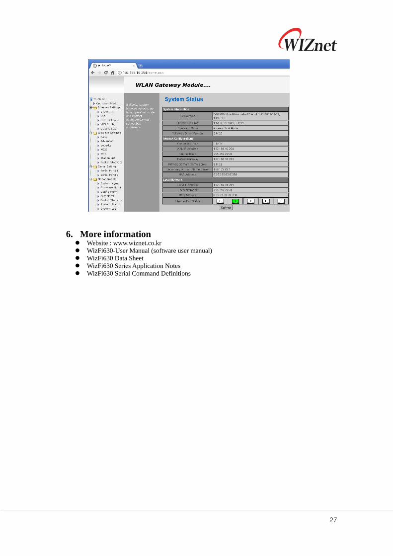
27
6. More information Website : www.wiznet.co.kr WizFi630-User Manual (software user manual) WizFi630 Data Sheet WizFi630 Series Application Notes WizFi630 Serial Command Definitions


![CTX700 EN - file.hstatic.netfile.hstatic.net/1000302780/file/ct-x700.pdf · cr TEMPO/TAP button ☞EN-9 cs FUNCTION button ☞EN-40 ct Number keys ☞EN-4 dk [–] and [+] keys ☞EN-4](https://img.pdfslide.us/doc/110x75/5e032666d9e2ea2f2041fd6b/ctx700-en-file-cr-tempotap-button-aen-9-cs-function-button-aen-40-ct-number.jpg)