Embed Size (px)
Citation preview
Serial ATA AHCI 1.2 Specification Revision 1_2.doc
i
SSeerriiaall AATTAA
AAddvvaanncceedd HHoosstt CCoonnttrroolllleerr IInntteerrffaaccee
((AAHHCCII)) 11..22
Revision 1_2.doc
Revision 1_2.doc Serial ATA AHCI 1.2 Specification
ii
Advanced Host Controller Interface revision 1.2 specification available for download at http://developer.intel.com. Ratified on April 9, 2007.
SPECIFICATION DISCLAIMER
THIS SPECIFICATION IS PROVIDED TO YOU “AS IS” WITH NO WARRANTIES WHATSOEVER, INCLUDING ANY WARRANTY OF MERCHANTABILITY, NON-INFRINGEMENT, OR FITNESS FOR ANY PARTICULAR PURPOSE. THE AUTHORS OF THIS SPECIFICATION DISCLAIM ALL LIABILITY, INCLUDING LIABILITY FOR INFRINGEMENT OF ANY PROPRIETARY RIGHTS, RELATING TO USE OR IMPLEMENTATION OF INFORMATION IN THIS SPECIFICATION. THE AUTHORS DO NOT WARRANT OR REPRESENT THAT SUCH USE WILL NOT INFRINGE ANY SUCH RIGHTS. THE PROVISION OF THIS SPECIFICATION TO YOU DOES NOT PROVIDE YOU WITH ANY LICENSE, EXPRESS OR IMPLIED, BY ESTOPPEL OR OTHERWISE, TO ANY INTELLECTUAL PROPERTY RIGHTS.
Copyright 2003-2007, Intel Corporation. All rights reserved.
All product names, trademarks, registered trademarks, and/or servicemarks may be claimed as the property of their respective owners.
AHCI Editor:
Amber Huffman Intel Corporation MS: JF2-53 2111 NE 25th Avenue Hillsboro, OR 97124 [email protected]
Serial ATA AHCI 1.2 Specification Revision 1_2.doc
iii
Table of Contents
1 INTRODUCTION ............................................................................................................. 1 1.1 Overview......................................................................................................................................... 1 1.2 Scope.............................................................................................................................................. 1 1.3 Outside of Scope ............................................................................................................................ 1 1.4 Block Diagram ................................................................................................................................ 1 1.5 Conventions.................................................................................................................................... 3 1.6 Definitions ....................................................................................................................................... 4
1.6.1 command list ..........................................................................................................................................4 1.6.2 command slot.........................................................................................................................................4 1.6.3 cs............................................................................................................................................................4 1.6.4 D2H........................................................................................................................................................4 1.6.5 device.....................................................................................................................................................4 1.6.6 FIS..........................................................................................................................................................4 1.6.7 H2D........................................................................................................................................................4 1.6.8 HBA........................................................................................................................................................4 1.6.9 n/a ..........................................................................................................................................................4 1.6.10 port .........................................................................................................................................................4 1.6.11 PRD........................................................................................................................................................4 1.6.12 queue .....................................................................................................................................................4 1.6.13 register memory .....................................................................................................................................4 1.6.14 Task File.................................................................................................................................................5 1.6.15 system memory......................................................................................................................................5
1.7 Theory of Operation........................................................................................................................ 5 1.8 Interaction with Legacy Software.................................................................................................... 5 1.9 References ..................................................................................................................................... 6
2 HBA CONFIGURATION REGISTERS................................................................................... 7 2.1 PCI Header ..................................................................................................................................... 7
2.1.1 Offset 00h: ID - Identifiers ......................................................................................................................7 2.1.2 Offset 04h: CMD - Command.................................................................................................................7 2.1.3 Offset 06h: STS - Device Status.............................................................................................................8 2.1.4 Offset 08h: RID - Revision ID .................................................................................................................8 2.1.5 Offset 09h: CC - Class Code..................................................................................................................8 2.1.6 Offset 0Ch: CLS – Cache Line Size .......................................................................................................8 2.1.7 Offset 0Dh: MLT – Master Latency Timer ..............................................................................................9 2.1.8 Offset 0Eh: HTYPE – Header Type........................................................................................................9 2.1.9 Offset 0Fh: BIST – Built In Self Test (Optional)......................................................................................9 2.1.10 Offset 10h – 20h: BARS – Other Base Addresses (Optional) ................................................................9 2.1.11 Offset 24h: ABAR – AHCI Base Address ...............................................................................................9 2.1.12 Offset 2Ch: SS - Sub System Identifiers ................................................................................................9 2.1.13 Offset 30h: EROM – Expansion ROM (Optional) ...................................................................................9 2.1.14 Offset 34h: CAP – Capabilities Pointer.................................................................................................10 2.1.15 Offset 3Ch: INTR - Interrupt Information ..............................................................................................10 2.1.16 Offset 3Eh: MGNT – Minimum Grant (Optional)...................................................................................10 2.1.17 Offset 3Fh: MLAT – Maximum Latency (Optional) ...............................................................................10
2.2 PCI Power Management Capabilities........................................................................................... 10 2.2.1 Offset PMCAP: PID - PCI Power Management Capability ID...............................................................10 2.2.2 Offset PMCAP + 2h: PC – PCI Power Management Capabilities.........................................................10 2.2.3 Offset PMCAP + 4h: PMCS – PCI Power Management Control And Status........................................11
2.3 Message Signaled Interrupt Capability (Optional) ........................................................................ 11 2.3.1 Offset MSICAP: MID – Message Signaled Interrupt Identifiers ............................................................11 2.3.2 Offset MSICAP + 2h: MC – Message Signaled Interrupt Message Control..........................................11 2.3.3 Offset MSICAP + 4h: MA – Message Signaled Interrupt Message Address ........................................12 2.3.4 Offset MSICAP + (8h or Ch): MD – Message Signaled Interrupt Message Data..................................12 2.3.5 Offset MSICAP + 8h: MUA – Message Signaled Interrupt Upper Address (Optional)..........................12
2.4 Serial ATA Capability (Optional)................................................................................................... 12 2.4.1 Offset SATACAP: SATACR0 – Serial ATA Capability Register 0 ........................................................12
Revision 1_2.doc Serial ATA AHCI 1.2 Specification
iv
2.4.2 Offset SATACAP + 4h: SATACR1 – Serial ATA Capability Register 1 ................................................12 2.5 Other Capability Pointers.............................................................................................................. 13
3 HBA MEMORY REGISTERS ........................................................................................... 14 3.1 Generic Host Control .................................................................................................................... 14
3.1.1 Offset 00h: CAP – HBA Capabilities.....................................................................................................14 3.1.2 Offset 04h: GHC – Global HBA Control................................................................................................16 3.1.3 Offset 08h: IS – Interrupt Status Register.............................................................................................17 3.1.4 Offset 0Ch: PI – Ports Implemented.....................................................................................................17 3.1.5 Offset 10h: VS – AHCI Version ............................................................................................................18 3.1.6 Offset 14h: CCC_CTL – Command Completion Coalescing Control....................................................18 3.1.7 Offset 18h: CCC_PORTS – Command Completion Coalescing Ports .................................................19 3.1.8 Offset 1Ch: EM_LOC – Enclosure Management Location ...................................................................19 3.1.9 Offset 20h: EM_CTL – Enclosure Management Control ......................................................................19 3.1.10 Offset 24h: CAP2 – HBA Capabilities Extended...................................................................................20 3.1.11 Offset 28h: BOHC – BIOS/OS Handoff Control and Status..................................................................20
3.2 Vendor Specific Registers ............................................................................................................ 21 3.3 Port Registers (one set per port) .................................................................................................. 21
3.3.1 Offset 00h: PxCLB – Port x Command List Base Address ...................................................................21 3.3.2 Offset 04h: PxCLBU – Port x Command List Base Address Upper 32-bits ..........................................21 3.3.3 Offset 08h: PxFB – Port x FIS Base Address.......................................................................................21 3.3.4 Offset 0Ch: PxFBU – Port x FIS Base Address Upper 32-bits .............................................................21 3.3.5 Offset 10h: PxIS – Port x Interrupt Status ............................................................................................22 3.3.6 Offset 14h: PxIE – Port x Interrupt Enable ...........................................................................................23 3.3.7 Offset 18h: PxCMD – Port x Command and Status..............................................................................24 3.3.8 Offset 20h: PxTFD – Port x Task File Data ..........................................................................................26 3.3.9 Offset 24h: PxSIG – Port x Signature...................................................................................................26 3.3.10 Offset 28h: PxSSTS – Port x Serial ATA Status (SCR0: SStatus) .......................................................27 3.3.11 Offset 2Ch: PxSCTL – Port x Serial ATA Control (SCR2: SControl) ....................................................27 3.3.12 Offset 30h: PxSERR – Port x Serial ATA Error (SCR1: SError) ...........................................................29 3.3.13 Offset 34h: PxSACT – Port x Serial ATA Active (SCR3: SActive) ........................................................30 3.3.14 Offset 38h: PxCI – Port x Command Issue...........................................................................................30 3.3.15 Offset 3Ch: PxSNTF – Port x Serial ATA Notification (SCR4: SNotification)........................................31 3.3.16 Offset 40h: PxFBS: Port x FIS-based Switching Control ......................................................................31 3.3.17 Offset 70h to 7Fh: PxVS – Vendor Specific..........................................................................................31
4 SYSTEM MEMORY STRUCTURES .................................................................................... 32 4.1 HBA Memory Space Usage.......................................................................................................... 32 4.2 Port Memory Usage...................................................................................................................... 33
4.2.1 Received FIS Structure ........................................................................................................................34 4.2.2 Command List Structure.......................................................................................................................35 4.2.3 Command Table...................................................................................................................................38
5 DATA TRANSFER OPERATION........................................................................................ 40 5.1 Introduction ................................................................................................................................... 40 5.2 HBA Controller State Machine (Normative).................................................................................. 40
5.2.1 Variables ..............................................................................................................................................40 5.2.2 HBA Idle States....................................................................................................................................40
5.3 HBA Port State Machine (Normative)........................................................................................... 42 5.3.1 Variables ..............................................................................................................................................42 5.3.2 Port Idle States.....................................................................................................................................44 5.3.3 FIS-based Switching Specific States....................................................................................................48 5.3.4 Power Management States ..................................................................................................................49 5.3.5 Non-Data FIS Receive States ..............................................................................................................50 5.3.6 Command Transfer States ...................................................................................................................51 5.3.7 ATAPI Command Transfer States........................................................................................................53 5.3.8 D2H Register FIS Receive States ........................................................................................................53 5.3.9 PIO Setup Receive States....................................................................................................................55 5.3.10 Data Transmit States............................................................................................................................56 5.3.11 Data Receive States.............................................................................................................................57
Serial ATA AHCI 1.2 Specification Revision 1_2.doc
v
5.3.12 DMA Setup Receive States..................................................................................................................58 5.3.13 Set Device Bits States..........................................................................................................................59 5.3.14 Unknown FIS Receive States...............................................................................................................60 5.3.15 BIST States ..........................................................................................................................................61 5.3.16 Error States ..........................................................................................................................................61
5.4 HBA Rules (Normative) ................................................................................................................ 63 5.4.1 PRD Byte Count Updates.....................................................................................................................63 5.4.2 PRD Interrupt .......................................................................................................................................63
5.5 System Software Rules (Normative) ............................................................................................ 64 5.5.1 Basic Steps when Building a Command...............................................................................................64 5.5.2 Setting CH(pFreeSlot).P.......................................................................................................................64 5.5.3 Processing Completed Commands......................................................................................................64
5.6 Transfer Examples (Informative) .................................................................................................. 65 5.6.1 Macro States ........................................................................................................................................65 5.6.2 DMA Data Transfers.............................................................................................................................65 5.6.3 PIO Data Transfers ..............................................................................................................................67 5.6.4 Native Queued Command Transfers....................................................................................................69 5.6.5 FIS-based Switching Command Transfers...........................................................................................72
6 ERROR REPORTING AND RECOVERY ............................................................................... 76 6.1 Error Types ................................................................................................................................... 76
6.1.1 System Memory Errors.........................................................................................................................76 6.1.2 Interface Errors.....................................................................................................................................76 6.1.3 Port Multiplier Errors.............................................................................................................................77 6.1.4 Taskfile Errors ......................................................................................................................................77 6.1.5 Command List Overflow .......................................................................................................................78 6.1.6 Command List Underflow .....................................................................................................................78 6.1.7 Native Command Queuing Tag Errors .................................................................................................78 6.1.8 PIO Data Transfer Errors .....................................................................................................................78 6.1.9 SYNC Escape by device ......................................................................................................................79 6.1.10 Device responds to FIS with R_ERR....................................................................................................79 6.1.11 CRC error in received FIS ....................................................................................................................79 6.1.12 D2H FIS received without active command slot ...................................................................................79
6.2 Error Recovery.............................................................................................................................. 80 6.2.1 HBA Aborting a Transfer ......................................................................................................................80 6.2.2 Software Error Recovery ......................................................................................................................80
7 HOT PLUG OPERATION ................................................................................................ 82 7.1 Platforms that Support Cold Presence Detect.............................................................................. 82
7.1.1 Device Hot Unplugged .........................................................................................................................82 7.1.2 Device Hot Plugged..............................................................................................................................82
7.2 Platforms that Support Mechanical Presence Switches............................................................... 82 7.3 Native Hot Plug Support ............................................................................................................... 82
7.3.1 Hot Plug Removal Detection and Power Management Interaction (Informative)..................................82 7.4 Interaction of the Command List and Port Change Status........................................................... 83
8 POWER MANAGEMENT OPERATION ................................................................................ 84 8.1 Introduction ................................................................................................................................... 84 8.2 Power State Mappings.................................................................................................................. 84 8.3 Power State Transitions ............................................................................................................... 85
8.3.1 Interface Power Management ..............................................................................................................85 8.3.2 Device D1, D2, and D3 States .............................................................................................................86 8.3.3 HBA D3 state........................................................................................................................................86
8.4 PME .............................................................................................................................................. 87 9 PORT MULTIPLIER SUPPORT......................................................................................... 88
9.1 Command Based Switching ......................................................................................................... 88 9.1.1 Non-Queued Operation ........................................................................................................................88
Revision 1_2.doc Serial ATA AHCI 1.2 Specification
vi
9.1.2 Queued Operation................................................................................................................................89 9.2 Port Multiplier Enumeration .......................................................................................................... 89 9.3 FIS-based Switching..................................................................................................................... 89
9.3.1 Configuration........................................................................................................................................89 9.3.2 Command Ordering..............................................................................................................................91 9.3.3 FIS Receive Area .................................................................................................................................91 9.3.4 DMA Context ........................................................................................................................................92 9.3.5 Data FIS transfers to the device – locking the interface .......................................................................92 9.3.6 Error Handling ......................................................................................................................................92 9.3.7 PxTFD Register Information.................................................................................................................94 9.3.8 SYNC Escape and setting the ‘R’ bit in Command Headers ................................................................94 9.3.9 FIS-based switching and Device Enumeration.....................................................................................94
10 PLATFORM COMMUNICATION ..................................................................................... 95 10.1 Software Initialization of HBA.................................................................................................... 95
10.1.1 Firmware Specific Initialization .............................................................................................................95 10.1.2 System Software Specific Initialization .................................................................................................95
10.2 Hardware Prerequisites to Enable/Disable GHC.AE ................................................................ 96 10.3 Software Manipulation of Port DMA Engines............................................................................ 97
10.3.1 Start (PxCMD.ST) ................................................................................................................................97 10.3.2 FIS Receive Enable (PxCMD.FRE)......................................................................................................97
10.4 Reset......................................................................................................................................... 98 10.4.1 Software Reset.....................................................................................................................................98 10.4.2 Port Reset ............................................................................................................................................98 10.4.3 HBA Reset ...........................................................................................................................................99
10.5 Interface Speed Support ........................................................................................................... 99 10.6 BIOS/OS Handoff Mechanism .................................................................................................. 99
10.6.1 Default / reset state ............................................................................................................................100 10.6.2 BIOS declares ownership request ......................................................................................................100 10.6.3 OS declares ownership request .........................................................................................................100 10.6.4 BIOS releases ownership...................................................................................................................100
10.7 Interrupts ................................................................................................................................. 101 10.7.1 Tiered Operation ................................................................................................................................101 10.7.2 HBA/SW Interaction ...........................................................................................................................101 10.7.3 Disabling Device Interrupts (NIEN Bit in Device Control Register) .....................................................104
10.8 Mechanical Presence Switch Operation ................................................................................. 104 10.9 Cold Presence Detect Operation ............................................................................................ 104 10.10 Staggered Spin-up Operation ................................................................................................. 104
10.10.1 Interaction of PxSCTL.DET and PxCMD.SUD ...............................................................................105 10.10.2 Spin-Up Procedure (Informative)....................................................................................................105 10.10.3 Preparing for Low Power System State (Informative).....................................................................105 10.10.4 When to Enter Listen Mode (Informative).......................................................................................106
10.11 Asynchronous Notification ...................................................................................................... 106 10.11.1 Notifications from Devices Connected to a Port Multiplier..............................................................106
10.12 Activity LED............................................................................................................................. 107 10.13 BIST ........................................................................................................................................ 107 10.14 Index-Data Pair ....................................................................................................................... 107
10.14.1 Rules/Restrictions ..........................................................................................................................108 10.14.2 IDP Index Register Format.............................................................................................................108 10.14.3 IDP Data Register Format ..............................................................................................................108 10.14.4 Access Mechanism ........................................................................................................................109 10.14.5 Index-Data Pair Discovery..............................................................................................................109
11 COMMAND COMPLETION COALESCING ....................................................................... 110 11.1 Command Completion Definition ............................................................................................ 110 11.2 Timer Definition ....................................................................................................................... 110 11.3 Selected Ports......................................................................................................................... 110 11.4 Interrupt Definition................................................................................................................... 110 11.5 Enable and Disable Behavior.................................................................................................. 111
Serial ATA AHCI 1.2 Specification Revision 1_2.doc
vii
11.6 Software Behavior................................................................................................................... 111 11.6.1 Initialization ........................................................................................................................................111 11.6.2 Errors and Hot Plug Events................................................................................................................111 11.6.3 CCC Interrupt Handling ......................................................................................................................112 11.6.4 Updating Timeout Value or Number of Command Completions.........................................................112
11.7 Example (Informative) ............................................................................................................. 112 12 ENCLOSURE MANAGEMENT...................................................................................... 114
12.1 Mechanism.............................................................................................................................. 114 12.2 Message Format ..................................................................................................................... 115
12.2.1 LED message type.............................................................................................................................116 12.2.2 SAF-TE message type .......................................................................................................................117 12.2.3 SES-2 message type..........................................................................................................................117
13 INFORMATIVE APPENDIX ......................................................................................... 119 13.1 Port Selector Support.............................................................................................................. 119 13.2 Legacy ATAPI Device Seek Complete Behavior .................................................................... 119
Revision 1_2.doc Serial ATA AHCI 1.2 Specification
viii
Table of Figures Figure 1: IA Based System Diagram..............................................................................................................................2 Figure 2: Embedded System Diagram ...........................................................................................................................3 Figure 3: Example of HBA Silicon Supporting Both Legacy and AHCI Interfaces..........................................................6 Figure 4: HBA Memory Space Usage ..........................................................................................................................32 Figure 5: Port System Memory Structures ...................................................................................................................33 Figure 6: Received FIS Organization ...........................................................................................................................34 Figure 7: Command List Structure ...............................................................................................................................35 Figure 8: DW 0 – Description Information ....................................................................................................................36 Figure 9: DW 1 - Command Status ..............................................................................................................................36 Figure 10: DW 2 – Command Table Base Address .....................................................................................................36 Figure 11: DW 3 – Command Table Base Address Upper...........................................................................................37 Figure 12: DW 4-7 – Reserved.....................................................................................................................................37 Figure 13: Command Table .........................................................................................................................................38 Figure 14: DW 0 – Data Base Address ........................................................................................................................39 Figure 15: DW 1 – Data Base Address Upper .............................................................................................................39 Figure 16: DW 2 – Reserved........................................................................................................................................39 Figure 17: DW 3 – Description Information ..................................................................................................................39 Figure 18: HBA Error Handling Behavior .....................................................................................................................61 Figure 19: Power State Hierarchy ................................................................................................................................84 Figure 20: FIS Receive Area for FIS-based Switching .................................................................................................92 Figure 21: Interrupt Tiers............................................................................................................................................101 Figure 22: MSI vs. PCI IRQ Actions ...........................................................................................................................102 Figure 23: Port/CCC and MSI Message Mapping, Example 1 ...................................................................................103 Figure 24: Port and MSI Message Mapping, Example 2 ............................................................................................103 Figure 25: Enclosure Management Buffer Location ...................................................................................................115
Serial ATA AHCI 1.2 Specification Revision 1_2.doc
1
1 Introduction 1.1 Overview
This specification defines the functional behavior and software interface of the Advanced Host Controller Interface, which is a hardware mechanism that allows software to communicate with Serial ATA devices. AHCI is a PCI class device that acts as a data movement engine between system memory and Serial ATA devices.
AHCI host devices (referred to as host bus adapters, or HBA) support from 1 to 32 ports. An HBA must support ATA and ATAPI devices, and must support both the PIO and DMA protocols. An HBA may optionally support a command list on each port for overhead reduction, and to support Serial ATA Native Command Queuing via the FPDMA Queued Command protocol for each device of up to 32 entries. An HBA may optionally support 64-bit addressing.
AHCI describes a system memory structure which contains a generic area for control and status, and a table of entries describing a command list (an HBA which does not support a command list shall have a depth of one for this table). Each command list entry contains information necessary to program an SATA device, and a pointer to a descriptor table for transferring data between system memory and the device.
1.2 Scope
AHCI encompasses a PCI device. It contains a PCI BAR (Base Address Register) to implement native SATA features. AHCI specifies the following features:
• Support for 32 ports • 64-bit addressing • Elimination of Master / Slave Handling • Large LBA support • Hot Plug • Power Management • HW Assisted Native Command Queuing • Staggered Spin-up • Cold device presence detect • Serial ATA superset registers • Activity LED generation • Port Multiplier
1.3 Outside of Scope
AHCI does not contain information relevant to implementing the Transport, Link or Phy layers of Serial ATA as this is wholly described in the Serial ATA 1.0a specification.
AHCI does not specify ATA legacy behavior, such as the legacy I/O ranges, or Bus Master IDE. Allowances have been made in AHCI so that an HBA may implement these features for backward compatibility with older operating systems (for example, the location of the memory BAR for AHCI is after the BAR locations for both native IDE and bus master IDE).
1.4 Block Diagram
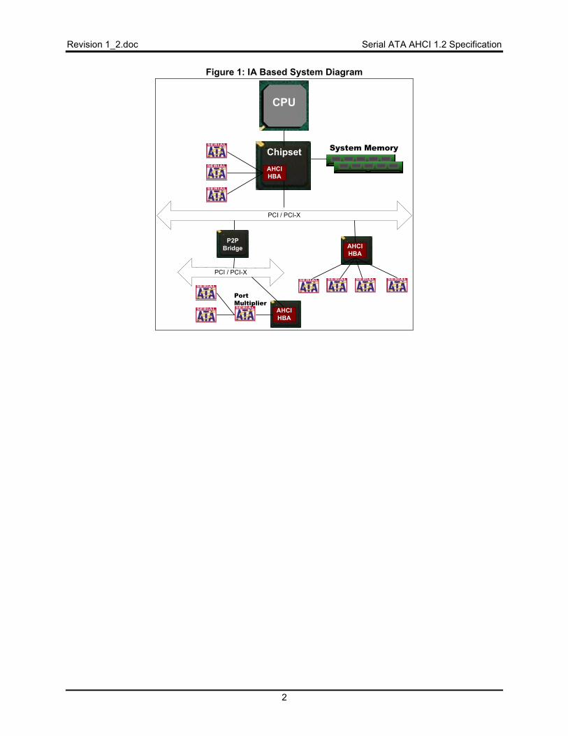
In Figure 1, several AHCI HBAs are attached in a typical computer system. One HBA is integrated in the core chipset. Another sits off the first available PCI/PCI-X bus. (PCI is used as a reference name. The bus can be any PCI-like bus, such as PCI-X, PCI-Express, HyperTransport, etc.) The intent is to be compliant with the PCI base specification. Compliance with non-PCI specifications is dependant upon those specifications being compliant/compatible with PCI.
A final HBA sits off a second PCI bus that exists behind a PCI-PCI bridge. This last HBA has one port attached to a Port Multiplier
Revision 1_2.doc Serial ATA AHCI 1.2 Specification
2
Figure 1: IA Based System Diagram
PCI / PCI-X
CPU
ChipsetAHCIHBA
AHCIHBA
AHCIHBA
PCI / PCI-X
P2PBridge
PortMultiplier
System Memory
Serial ATA AHCI 1.2 Specification Revision 1_2.doc
3
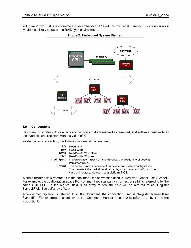
In Figure 2, two HBA are connected to an embedded CPU with its own local memory. This configuration would most likely be used in a RAID-type environment.
Figure 2: Embedded System Diagram
PCI / PCI-X
EmbeddedCPU
P2PBridge
Memory
PCI / PCI-X
AHCIHBA
AHCIHBA
NetworkI/F
Network
1.5 Conventions
Hardware must return ‘0’ for all bits and registers that are marked as reserved, and software must write all reserved bits and registers with the value of ‘0’.
Inside the register section, the following abbreviations are used: RO Read Only RW Read Write
RWC Read/Write ‘1’ to clear RW1 Read/Write ‘1’ to set
Impl. Spec. Implementation Specific – the HBA has the freedom to choose its implementation.
HwInit The default state is dependent on device and system configuration. The value is initialized at reset, either by an expansion ROM, or in the case of integrated devices, by a platform BIOS.
When a register bit is referred to in the document, the convention used is “Register Symbol.Field Symbol”. For example, the configuration space PCI command register parity error response bit is referred to by the name CMD.PEE. If the register field is an array of bits, the field will be referred to as “Register Symbol.Field Symbol(array offset)”.
When a memory field is referred to in the document, the convention used is “Register Name[Offset Symbol]”. For example, the pointer to the Command Header of port 0 is referred to by the name P0CLB[CH0].
Revision 1_2.doc Serial ATA AHCI 1.2 Specification
4
1.6 Definitions
1.6.1 command list
Defines commands located in system memory that an HBA processes. This is a list that may contain 1 to 32 entries (called command slots), and may contain any type of ATA or ATAPI command. The command list is advanced when the BSY, DRQ, and ERR bits of a Serial ATA device is cleared.
1.6.2 command slot
A command slot is one of the entries in the command list. The command slot contains the command to execute. Up to 32 slots (i.e. entries) are supported in a command list.
1.6.3 cs
cs is used to describe fields that have a command specific meaning.
1.6.4 D2H
D2H is an acronym for “device to HBA”. In the Serial ATA specifications, this acronym stands similarly for “device to host”. D2H is often used to describe the direction of transfer for a FIS.
1.6.5 device
A physical device, such as a hard disk drive (HDD) or an optical disk drive (ODD) that is either directly attached to an HBA port, or is attached through a Port Multiplier to an HBA port.
1.6.6 FIS
FIS is an acronym for “Frame Information Structure”. A FIS is a packet or frame of information that is transferred between the host and device. Refer to the Serial ATA 1.0a specification for more information.
1.6.7 H2D
H2D is an acronym for “HBA to device”. In the Serial ATA specifications, this acronym stands similarly for “host to device”. H2D is often used to describe the direction of transfer for a FIS.
1.6.8 HBA
HBA is an acronym for “host bus adapter”. A host bus adapter refers to the silicon that implements the AHCI specification to communicate between system memory and Serial ATA devices.
1.6.9 n/a
n/a is used to describe fields that are not applicable or unused for a particular command.
1.6.10 port
A physical port on the HBA, with a set of registers that control the DMA and link operations. A physical port may have several devices attached to it via a Port Multiplier.
1.6.11 PRD
PRD is an acronym for “physical region descriptor”. PRD entries describe the physical location and length of data to be transferred. Refer to section 4.2.3.3.
1.6.12 queue
Indicates the ATA command queue inside a Serial ATA device. This is differentiated from the command list in that a queue shall only exist in a Serial ATA device when all the commands in the HBA’s command list are Serial ATA native queuing commands.
1.6.13 register memory
Registers allocated in the memory space of the HBA. These registers are physically implemented in the HBA.
Serial ATA AHCI 1.2 Specification Revision 1_2.doc
5
1.6.14 Task File
Interface registers used for delivering commands to the device or posting status from the device. In Serial ATA, these registers are communicated as part of FIS payload fields. In later revisions of the ATA specification, these registers may be referred to as the Command and Control Block registers.
1.6.15 system memory
DRAM or “main” memory of a computer system, used to communicate data and command information between the host processor and the Serial ATA device.
1.7 Theory of Operation
AHCI takes the basics of the scatter/gather list concept of Bus Master IDE, and expand it to reduce CPU/software overhead and provide support for Serial ATA features such as hot plug, power management, and accessing of several devices without performing master/slave emulation.
Communication between a device and software moves from the task file via byte-wide accesses to a command FIS located in system memory that is fetched by the HBA. This reduces command setup time significantly, allowing for many more devices to be added to a single host controller. Software no longer communicates directly to a device via the task file.
AHCI is defined to keep the HBA relatively simple so that it can act as a data mover. An HBA implementing AHCI is not required to parse any of the ATA or ATAPI commands as they are transferred to the device, although it is not prohibited from doing so.
All data transfers between the device and system memory occur through the HBA acting as a bus master to system memory. Whether the transaction is of a DMA type or a PIO type, the HBA fetches and stores data to memory, offloading the CPU. There is no accessible data port.
All transfers are performed using DMA. The use of the PIO command type is strongly discouraged. PIO has limited support for errors – for example, the ending status field of a PIO transfer is given to the HBA during the PIO Setup FIS, before the data is transferred. However, some commands may only be performed via PIO commands (such as IDENTIFY DEVICE). Some HBA implementations may limit PIO support to one DRQ block of data per command.
The AHCI defines a standard mechanism for implementing a SATA command queue using the DMA Setup FIS. An HBA which supports queuing has individual slots in the Command List allocated in system memory for all the commands. Software can place a command into any empty slot, and upon notifying the HBA via a register access, the HBA shall fetch the command and transfer it. The tag that is returned in the DMA Setup FIS is used as an index into the command list to get the scatter/gather list used in the transfer.
This command list can be used by system software and the HBA even when non-queued commands need to be transferred. System software can still place multiple commands in the list, whether DMA, PIO, or ATAPI, and the HBA will walk the list transferring them.
This multiple-use of the command list is achieved by the HBA only moving its command list pointer when the BSY, DRQ, and ERR bits are cleared by the device. System software is responsible to ensure that queued and non-queued commands are not mixed in the command list for the same device.
1.8 Interaction with Legacy Software
AHCI is a self-contained specification that is intended to support all aspects of communicating with SATA devices, without having to utilize any legacy features such as shadow copies of the task file, snooping of bits in commands, etc.
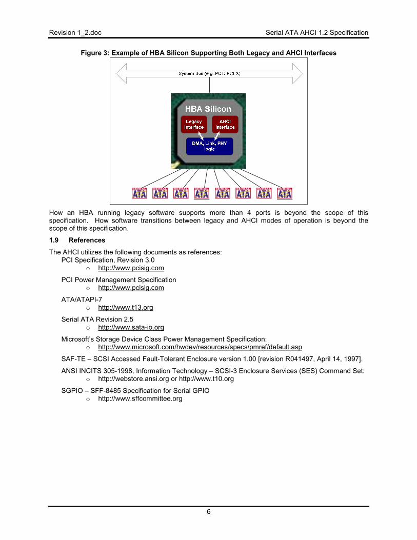
HBAs that support legacy software mechanisms must do so in a fashion that is transparent to AHCI. Legacy registers are not allowed to affect any bits in AHCI registers, nor is AHCI software allowed to affect any bits in legacy registers. Software written for AHCI is not allowed to utilize any of the legacy mechanisms to program devices. In essence, an HBA that supports both mechanisms must isolate its legacy and AHCI engines, as shown in Figure 3.
Revision 1_2.doc Serial ATA AHCI 1.2 Specification
6
Figure 3: Example of HBA Silicon Supporting Both Legacy and AHCI Interfaces
How an HBA running legacy software supports more than 4 ports is beyond the scope of this specification. How software transitions between legacy and AHCI modes of operation is beyond the scope of this specification.
1.9 References
The AHCI utilizes the following documents as references: PCI Specification, Revision 3.0
o http://www.pcisig.com
PCI Power Management Specification o http://www.pcisig.com
ATA/ATAPI-7 o http://www.t13.org
Serial ATA Revision 2.5 o http://www.sata-io.org
Microsoft’s Storage Device Class Power Management Specification: o http://www.microsoft.com/hwdev/resources/specs/pmref/default.asp
SAF-TE – SCSI Accessed Fault-Tolerant Enclosure version 1.00 [revision R041497, April 14, 1997].
ANSI INCITS 305-1998, Information Technology – SCSI-3 Enclosure Services (SES) Command Set: o http://webstore.ansi.org or http://www.t10.org
SGPIO – SFF-8485 Specification for Serial GPIO o http://www.sffcommittee.org
Serial ATA AHCI 1.2 Specification Revision 1_2.doc
7
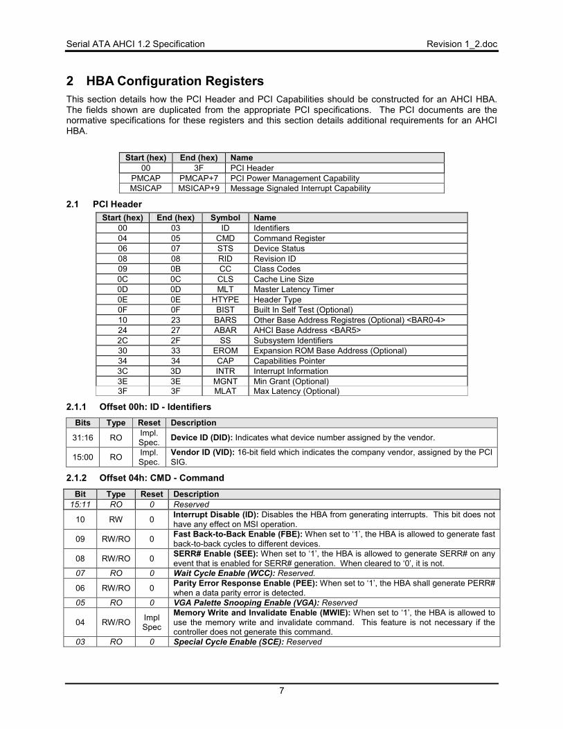
2 HBA Configuration Registers This section details how the PCI Header and PCI Capabilities should be constructed for an AHCI HBA. The fields shown are duplicated from the appropriate PCI specifications. The PCI documents are the normative specifications for these registers and this section details additional requirements for an AHCI HBA.
Start (hex) End (hex) Name
00 3F PCI Header PMCAP PMCAP+7 PCI Power Management Capability MSICAP MSICAP+9 Message Signaled Interrupt Capability
2.1 PCI Header Start (hex) End (hex) Symbol Name
00 03 ID Identifiers 04 05 CMD Command Register 06 07 STS Device Status 08 08 RID Revision ID 09 0B CC Class Codes 0C 0C CLS Cache Line Size 0D 0D MLT Master Latency Timer 0E 0E HTYPE Header Type 0F 0F BIST Built In Self Test (Optional) 10 23 BARS Other Base Address Registres (Optional) <BAR0-4> 24 27 ABAR AHCI Base Address <BAR5> 2C 2F SS Subsystem Identifiers 30 33 EROM Expansion ROM Base Address (Optional) 34 34 CAP Capabilities Pointer 3C 3D INTR Interrupt Information 3E 3E MGNT Min Grant (Optional) 3F 3F MLAT Max Latency (Optional)
2.1.1 Offset 00h: ID - Identifiers Bits Type Reset Description
31:16 RO Impl. Spec. Device ID (DID): Indicates what device number assigned by the vendor.
15:00 RO Impl. Spec.
Vendor ID (VID): 16-bit field which indicates the company vendor, assigned by the PCI SIG.
2.1.2 Offset 04h: CMD - Command
Bit Type Reset Description 15:11 RO 0 Reserved
10 RW 0 Interrupt Disable (ID): Disables the HBA from generating interrupts. This bit does not have any effect on MSI operation.
09 RW/RO 0 Fast Back-to-Back Enable (FBE): When set to ‘1’, the HBA is allowed to generate fast back-to-back cycles to different devices.
08 RW/RO 0 SERR# Enable (SEE): When set to ‘1’, the HBA is allowed to generate SERR# on any event that is enabled for SERR# generation. When cleared to ‘0’, it is not.
07 RO 0 Wait Cycle Enable (WCC): Reserved.
06 RW/RO 0 Parity Error Response Enable (PEE): When set to ‘1’, the HBA shall generate PERR# when a data parity error is detected.
05 RO 0 VGA Palette Snooping Enable (VGA): Reserved
04 RW/RO Impl Spec
Memory Write and Invalidate Enable (MWIE): When set to ‘1’, the HBA is allowed to use the memory write and invalidate command. This feature is not necessary if the controller does not generate this command.
03 RO 0 Special Cycle Enable (SCE): Reserved
Revision 1_2.doc Serial ATA AHCI 1.2 Specification
8
02 RW 0
Bus Master Enable (BME): Controls the HBA’s ability to act as a master for data transfers. When set to ‘1’, bus master activity is allowed. When cleared to ‘0’, the HBA stops and any active DMA engines return to an idle condition. It is the equivalent of clearing the memory space start bits (PxCMD.ST) in each port.
01 RW 0 Memory Space Enable (MSE): Controls access to the HBA’s register memory space.
00 RW/ RO
Impl Spec
I/O Space Enable (IOSE): Controls access to the HBA’s target I/O space. If the HBA also supports bus master IDE, this bit must be read/write. This bit should be read-only if bus master IDE is not supported by the HBA.
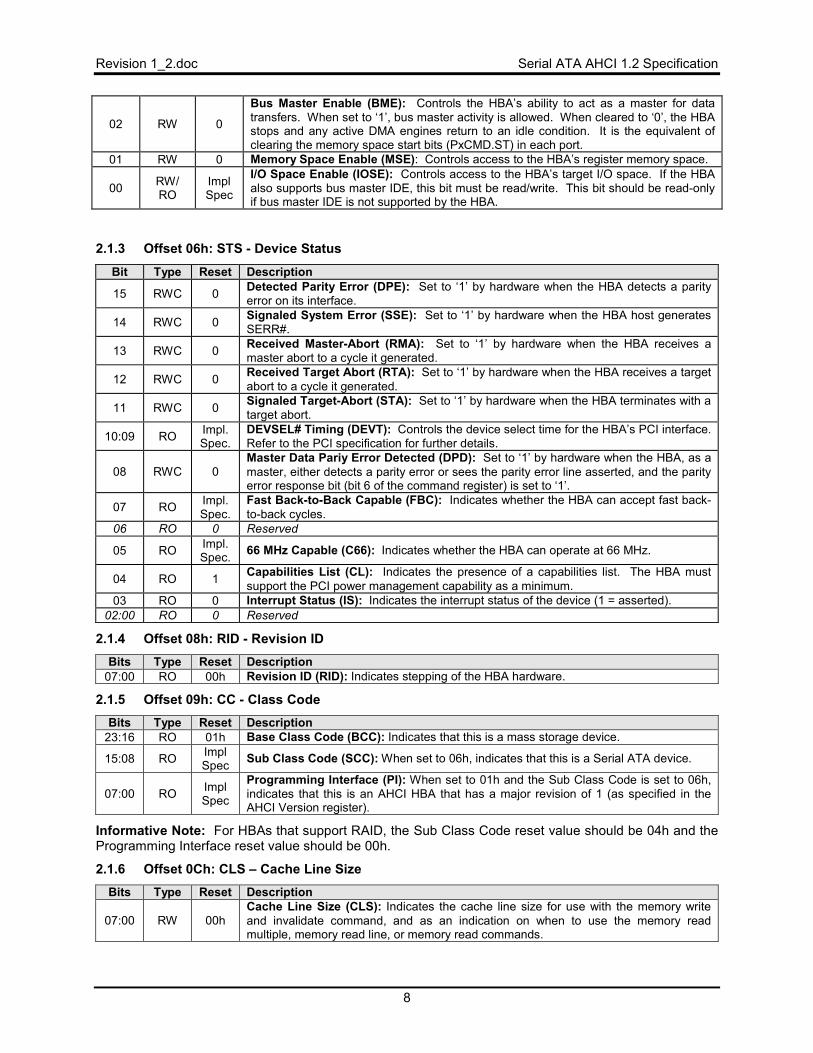
2.1.3 Offset 06h: STS - Device Status
Bit Type Reset Description
15 RWC 0 Detected Parity Error (DPE): Set to ‘1’ by hardware when the HBA detects a parity error on its interface.
14 RWC 0 Signaled System Error (SSE): Set to ‘1’ by hardware when the HBA host generates SERR#.
13 RWC 0 Received Master-Abort (RMA): Set to ‘1’ by hardware when the HBA receives a master abort to a cycle it generated.
12 RWC 0 Received Target Abort (RTA): Set to ‘1’ by hardware when the HBA receives a target abort to a cycle it generated.
11 RWC 0 Signaled Target-Abort (STA): Set to ‘1’ by hardware when the HBA terminates with a target abort.
10:09 RO Impl. Spec.
DEVSEL# Timing (DEVT): Controls the device select time for the HBA’s PCI interface. Refer to the PCI specification for further details.
08 RWC 0 Master Data Pariy Error Detected (DPD): Set to ‘1’ by hardware when the HBA, as a master, either detects a parity error or sees the parity error line asserted, and the parity error response bit (bit 6 of the command register) is set to ‘1’.
07 RO Impl. Spec.
Fast Back-to-Back Capable (FBC): Indicates whether the HBA can accept fast back-to-back cycles.
06 RO 0 Reserved
05 RO Impl. Spec. 66 MHz Capable (C66): Indicates whether the HBA can operate at 66 MHz.
04 RO 1 Capabilities List (CL): Indicates the presence of a capabilities list. The HBA must support the PCI power management capability as a minimum.
03 RO 0 Interrupt Status (IS): Indicates the interrupt status of the device (1 = asserted). 02:00 RO 0 Reserved
2.1.4 Offset 08h: RID - Revision ID Bits Type Reset Description
07:00 RO 00h Revision ID (RID): Indicates stepping of the HBA hardware.
2.1.5 Offset 09h: CC - Class Code Bits Type Reset Description
23:16 RO 01h Base Class Code (BCC): Indicates that this is a mass storage device.
15:08 RO Impl Spec Sub Class Code (SCC): When set to 06h, indicates that this is a Serial ATA device.
07:00 RO Impl Spec
Programming Interface (PI): When set to 01h and the Sub Class Code is set to 06h, indicates that this is an AHCI HBA that has a major revision of 1 (as specified in the AHCI Version register).
Informative Note: For HBAs that support RAID, the Sub Class Code reset value should be 04h and the Programming Interface reset value should be 00h.
2.1.6 Offset 0Ch: CLS – Cache Line Size Bits Type Reset Description
07:00 RW 00h Cache Line Size (CLS): Indicates the cache line size for use with the memory write and invalidate command, and as an indication on when to use the memory read multiple, memory read line, or memory read commands.
Serial ATA AHCI 1.2 Specification Revision 1_2.doc
9
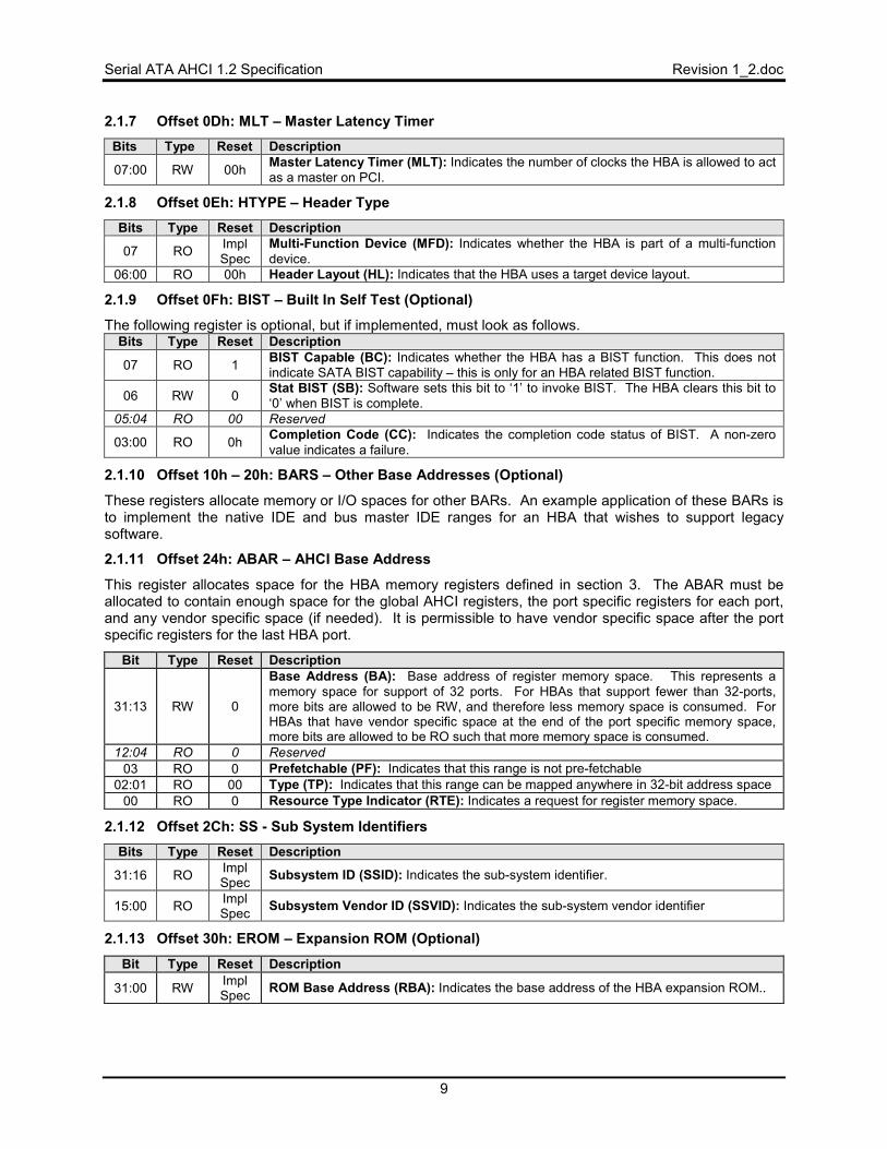
2.1.7 Offset 0Dh: MLT – Master Latency Timer Bits Type Reset Description
07:00 RW 00h Master Latency Timer (MLT): Indicates the number of clocks the HBA is allowed to act as a master on PCI.
2.1.8 Offset 0Eh: HTYPE – Header Type Bits Type Reset Description
07 RO Impl Spec
Multi-Function Device (MFD): Indicates whether the HBA is part of a multi-function device.
06:00 RO 00h Header Layout (HL): Indicates that the HBA uses a target device layout.
2.1.9 Offset 0Fh: BIST – Built In Self Test (Optional)
The following register is optional, but if implemented, must look as follows. Bits Type Reset Description
07 RO 1 BIST Capable (BC): Indicates whether the HBA has a BIST function. This does not indicate SATA BIST capability – this is only for an HBA related BIST function.
06 RW 0 Stat BIST (SB): Software sets this bit to ‘1’ to invoke BIST. The HBA clears this bit to ‘0’ when BIST is complete.
05:04 RO 00 Reserved
03:00 RO 0h Completion Code (CC): Indicates the completion code status of BIST. A non-zero value indicates a failure.
2.1.10 Offset 10h – 20h: BARS – Other Base Addresses (Optional)
These registers allocate memory or I/O spaces for other BARs. An example application of these BARs is to implement the native IDE and bus master IDE ranges for an HBA that wishes to support legacy software.
2.1.11 Offset 24h: ABAR – AHCI Base Address
This register allocates space for the HBA memory registers defined in section 3. The ABAR must be allocated to contain enough space for the global AHCI registers, the port specific registers for each port, and any vendor specific space (if needed). It is permissible to have vendor specific space after the port specific registers for the last HBA port.
Bit Type Reset Description
31:13 RW 0
Base Address (BA): Base address of register memory space. This represents a memory space for support of 32 ports. For HBAs that support fewer than 32-ports, more bits are allowed to be RW, and therefore less memory space is consumed. For HBAs that have vendor specific space at the end of the port specific memory space, more bits are allowed to be RO such that more memory space is consumed.
12:04 RO 0 Reserved 03 RO 0 Prefetchable (PF): Indicates that this range is not pre-fetchable
02:01 RO 00 Type (TP): Indicates that this range can be mapped anywhere in 32-bit address space 00 RO 0 Resource Type Indicator (RTE): Indicates a request for register memory space.
2.1.12 Offset 2Ch: SS - Sub System Identifiers Bits Type Reset Description
31:16 RO Impl Spec Subsystem ID (SSID): Indicates the sub-system identifier.
15:00 RO Impl Spec Subsystem Vendor ID (SSVID): Indicates the sub-system vendor identifier
2.1.13 Offset 30h: EROM – Expansion ROM (Optional)
Bit Type Reset Description
31:00 RW Impl Spec ROM Base Address (RBA): Indicates the base address of the HBA expansion ROM..
Revision 1_2.doc Serial ATA AHCI 1.2 Specification
10
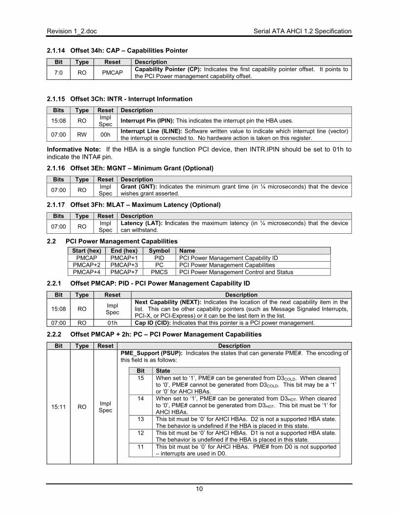
2.1.14 Offset 34h: CAP – Capabilities Pointer
Bit Type Reset Description
7:0 RO PMCAP Capability Pointer (CP): Indicates the first capability pointer offset. It points to the PCI Power management capability offset.
2.1.15 Offset 3Ch: INTR - Interrupt Information Bits Type Reset Description
15:08 RO Impl Spec Interrupt Pin (IPIN): This indicates the interrupt pin the HBA uses.
07:00 RW 00h Interrupt Line (ILINE): Software written value to indicate which interrupt line (vector) the interrupt is connected to. No hardware action is taken on this register.
Informative Note: If the HBA is a single function PCI device, then INTR.IPIN should be set to 01h to indicate the INTA# pin.
2.1.16 Offset 3Eh: MGNT – Minimum Grant (Optional) Bits Type Reset Description
07:00 RO Impl Spec
Grant (GNT): Indicates the minimum grant time (in ¼ microseconds) that the device wishes grant asserted.
2.1.17 Offset 3Fh: MLAT – Maximum Latency (Optional) Bits Type Reset Description
07:00 RO Impl Spec
Latency (LAT): Indicates the maximum latency (in ¼ microseconds) that the device can withstand.
2.2 PCI Power Management Capabilities Start (hex) End (hex) Symbol Name
PMCAP PMCAP+1 PID PCI Power Management Capability ID PMCAP+2 PMCAP+3 PC PCI Power Management Capabilities PMCAP+4 PMCAP+7 PMCS PCI Power Management Control and Status
2.2.1 Offset PMCAP: PID - PCI Power Management Capability ID
Bit Type Reset Description
15:08 RO Impl Spec
Next Capability (NEXT): Indicates the location of the next capability item in the list. This can be other capability pointers (such as Message Signaled Interrupts, PCI-X, or PCI-Express) or it can be the last item in the list.
07:00 RO 01h Cap ID (CID): Indicates that this pointer is a PCI power management.
2.2.2 Offset PMCAP + 2h: PC – PCI Power Management Capabilities
Bit Type Reset Description
15:11 RO Impl Spec
PME_Support (PSUP): Indicates the states that can generate PME#. The encoding of this field is as follows:
Bit State 15 When set to ‘1’, PME# can be generated from D3COLD. When cleared
to ‘0’, PME# cannot be generated from D3COLD. This bit may be a ‘1’ or ‘0’ for AHCI HBAs.
14 When set to ‘1’, PME# can be generated from D3HOT. When cleared to ‘0’, PME# cannot be generated from D3HOT. This bit must be ‘1’ for AHCI HBAs.
13 This bit must be ‘0’ for AHCI HBAs. D2 is not a supported HBA state. The behavior is undefined if the HBA is placed in this state.
12 This bit must be ‘0’ for AHCI HBAs. D1 is not a supported HBA state. The behavior is undefined if the HBA is placed in this state.
11 This bit must be ‘0’ for AHCI HBAs. PME# from D0 is not supported – interrupts are used in D0.
Serial ATA AHCI 1.2 Specification Revision 1_2.doc
11
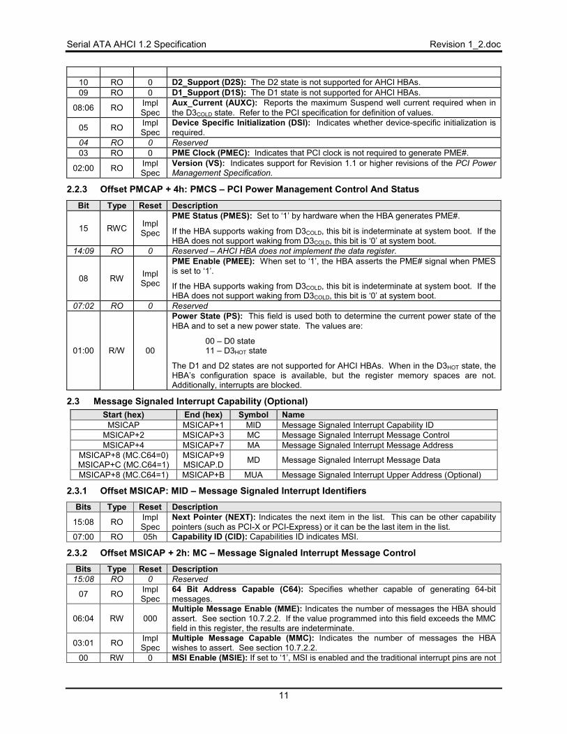
10 RO 0 D2_Support (D2S): The D2 state is not supported for AHCI HBAs. 09 RO 0 D1_Support (D1S): The D1 state is not supported for AHCI HBAs.
08:06 RO Impl Spec
Aux_Current (AUXC): Reports the maximum Suspend well current required when in the D3COLD state. Refer to the PCI specification for definition of values.
05 RO Impl Spec
Device Specific Initialization (DSI): Indicates whether device-specific initialization is required.
04 RO 0 Reserved 03 RO 0 PME Clock (PMEC): Indicates that PCI clock is not required to generate PME#.
02:00 RO Impl Spec
Version (VS): Indicates support for Revision 1.1 or higher revisions of the PCI Power Management Specification.
2.2.3 Offset PMCAP + 4h: PMCS – PCI Power Management Control And Status
Bit Type Reset Description
15 RWC Impl Spec
PME Status (PMES): Set to ‘1’ by hardware when the HBA generates PME#.
If the HBA supports waking from D3COLD, this bit is indeterminate at system boot. If the HBA does not support waking from D3COLD, this bit is ‘0’ at system boot.
14:09 RO 0 Reserved – AHCI HBA does not implement the data register.
08 RW Impl Spec
PME Enable (PMEE): When set to ‘1’, the HBA asserts the PME# signal when PMES is set to ‘1’.
If the HBA supports waking from D3COLD, this bit is indeterminate at system boot. If the HBA does not support waking from D3COLD, this bit is ‘0’ at system boot.
07:02 RO 0 Reserved
01:00 R/W 00
Power State (PS): This field is used both to determine the current power state of the HBA and to set a new power state. The values are:
00 – D0 state 11 – D3HOT state
The D1 and D2 states are not supported for AHCI HBAs. When in the D3HOT state, the HBA’s configuration space is available, but the register memory spaces are not. Additionally, interrupts are blocked.
2.3 Message Signaled Interrupt Capability (Optional) Start (hex) End (hex) Symbol Name
MSICAP MSICAP+1 MID Message Signaled Interrupt Capability ID MSICAP+2 MSICAP+3 MC Message Signaled Interrupt Message Control MSICAP+4 MSICAP+7 MA Message Signaled Interrupt Message Address
MSICAP+8 (MC.C64=0) MSICAP+C (MC.C64=1)
MSICAP+9 MSICAP.D MD Message Signaled Interrupt Message Data
MSICAP+8 (MC.C64=1) MSICAP+B MUA Message Signaled Interrupt Upper Address (Optional)
2.3.1 Offset MSICAP: MID – Message Signaled Interrupt Identifiers Bits Type Reset Description
15:08 RO Impl Spec
Next Pointer (NEXT): Indicates the next item in the list. This can be other capability pointers (such as PCI-X or PCI-Express) or it can be the last item in the list.
07:00 RO 05h Capability ID (CID): Capabilities ID indicates MSI.
2.3.2 Offset MSICAP + 2h: MC – Message Signaled Interrupt Message Control Bits Type Reset Description
15:08 RO 0 Reserved
07 RO Impl Spec
64 Bit Address Capable (C64): Specifies whether capable of generating 64-bit messages.
06:04 RW 000 Multiple Message Enable (MME): Indicates the number of messages the HBA should assert. See section 10.7.2.2. If the value programmed into this field exceeds the MMC field in this register, the results are indeterminate.
03:01 RO Impl Spec
Multiple Message Capable (MMC): Indicates the number of messages the HBA wishes to assert. See section 10.7.2.2.
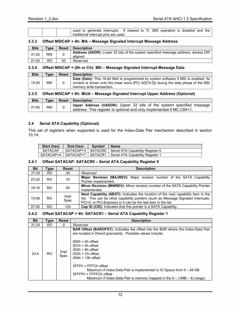
00 RW 0 MSI Enable (MSIE): If set to ‘1’, MSI is enabled and the traditional interrupt pins are not
Revision 1_2.doc Serial ATA AHCI 1.2 Specification
12
used to generate interrupts. If cleared to ‘0’, MSI operation is disabled and the traditional interrupt pins are used.
2.3.3 Offset MSICAP + 4h: MA – Message Signaled Interrupt Message Address Bits Type Reset Description
31:02 RW 0 Address (ADDR): Lower 32 bits of the system specified message address, always DW aligned.
01:00 RO 00 Reserved
2.3.4 Offset MSICAP + (8h or Ch): MD – Message Signaled Interrupt Message Data Bits Type Reset Description
15:00 RW 0 Data (Data): This 16-bit field is programmed by system software if MSI is enabled. Its content is driven onto the lower word (PCI AD[15:0]) during the data phase of the MSI memory write transaction.
2.3.5 Offset MSICAP + 8h: MUA – Message Signaled Interrupt Upper Address (Optional) Bits Type Reset Description
31:00 RW 0 Upper Address (UADDR): Upper 32 bits of the system specified message address. This register is optional and only implemented if MC.C64=1.
2.4 Serial ATA Capability (Optional)
This set of registers when supported is used for the Index-Data Pair mechanism described in section 10.14.
Start (hex) End (hex) Symbol Name SATACAP SATACAP+3 SATACR0 Serial ATA Capability Register 0
SATACAP+4 SATACAP+7 SATACR1 Serial ATA Capability Register 1
2.4.1 Offset SATACAP: SATACR0 – Serial ATA Capability Register 0
Bit Type Reset Description 31:24 RO 0h Reserved
23:20 RO 1h Major Revision (MAJREV): Major revision number of the SATA Capability Pointer implemented.
19:16 RO 0h Minor Revision (MINREV): Minor revision number of the SATA Capability Pointer implemented.
15:08 RO Impl Spec
Next Capability (NEXT): Indicates the location of the next capability item in the list. This can be other capability pointers (such as Message Signaled Interrupts, PCI-X, or PCI-Express) or it can be the last item in the list.
07:00 RO 12h Cap ID (CID): Indicates that this pointer is a SATA Capability.
2.4.2 Offset SATACAP + 4h: SATACR1 – Serial ATA Capability Register 1
Bit Type Reset Description 31:24 RO 0 Reserved
23:4 RO Impl Spec
BAR Offset (BAROFST): Indicates the offset into the BAR where the Index-Data Pair are located in Dword granularity. Possible values include: 000h = 0h offset 001h = 4h offset 002h = 8h offset 003h = Ch offset 004h = 10h offset …3FFFh = FFFCh offset
Maximum if Index-Data Pair is implemented in IO Space from 0 – 64 KB 3FFFFh = FFFFCh offset
Maximum if Index-Data Pair is memory mapped in the 0 – (1MB – 4) range)
Serial ATA AHCI 1.2 Specification Revision 1_2.doc
13
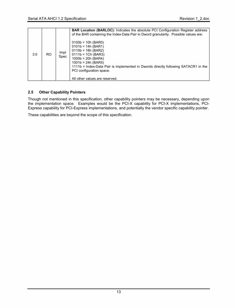
3:0 RO Impl Spec
BAR Location (BARLOC): Indicates the absolute PCI Configuration Register address of the BAR containing the Index-Data Pair in Dword granularity. Possible values are: 0100b = 10h (BAR0) 0101b = 14h (BAR1) 0110b = 18h (BAR2) 0111b = 1Ch (BAR3) 1000b = 20h (BAR4) 1001b = 24h (BAR5) 1111b = Index-Data Pair is implemented in Dwords directly following SATACR1 in the PCI configuration space. All other values are reserved.
2.5 Other Capability Pointers
Though not mentioned in this specification, other capability pointers may be necessary, depending upon the implementation space. Examples would be the PCI-X capability for PCI-X implementations, PCI-Express capability for PCI-Express implementations, and potentially the vendor specific capability pointer.
These capabilities are beyond the scope of this specification.
Revision 1_2.doc Serial ATA AHCI 1.2 Specification
14
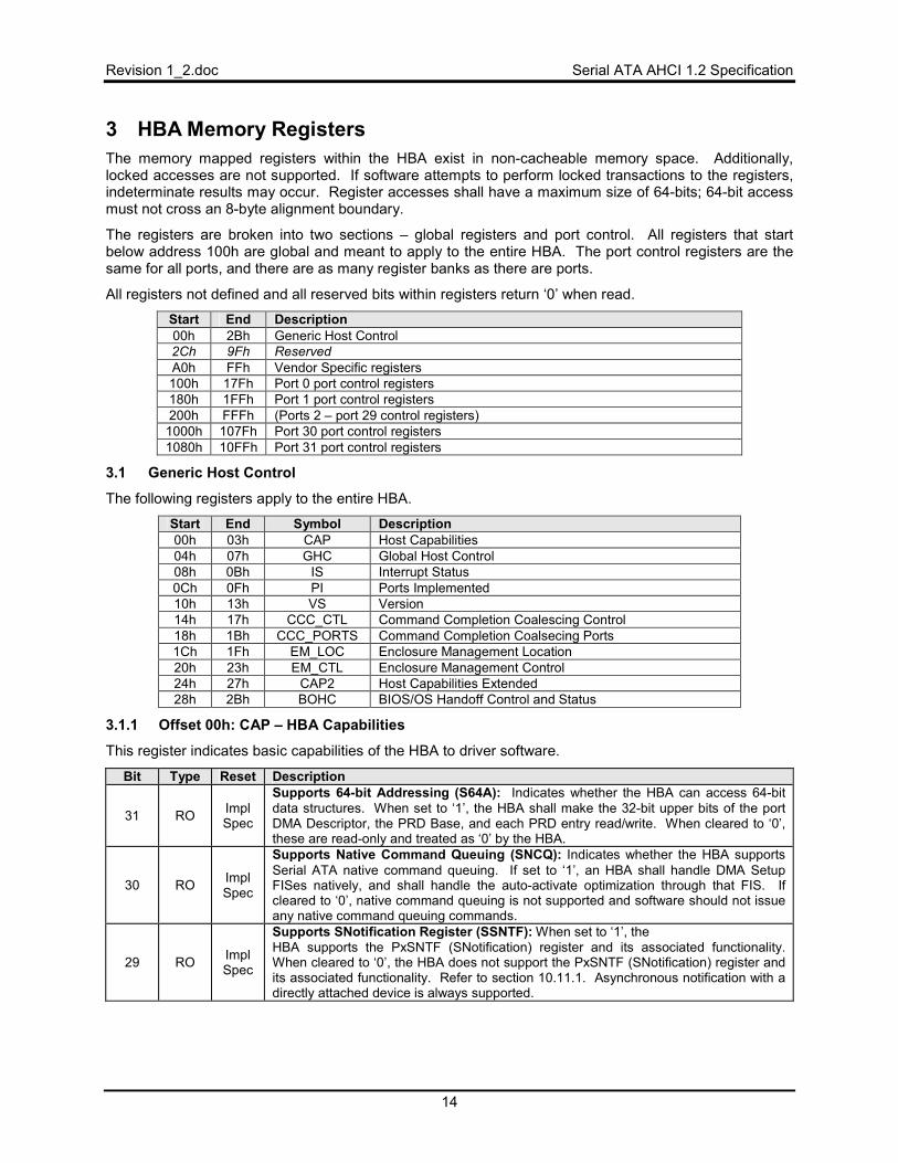
3 HBA Memory Registers The memory mapped registers within the HBA exist in non-cacheable memory space. Additionally, locked accesses are not supported. If software attempts to perform locked transactions to the registers, indeterminate results may occur. Register accesses shall have a maximum size of 64-bits; 64-bit access must not cross an 8-byte alignment boundary.
The registers are broken into two sections – global registers and port control. All registers that start below address 100h are global and meant to apply to the entire HBA. The port control registers are the same for all ports, and there are as many register banks as there are ports.
All registers not defined and all reserved bits within registers return ‘0’ when read.
Start End Description 00h 2Bh Generic Host Control 2Ch 9Fh Reserved A0h FFh Vendor Specific registers 100h 17Fh Port 0 port control registers 180h 1FFh Port 1 port control registers 200h FFFh (Ports 2 – port 29 control registers) 1000h 107Fh Port 30 port control registers 1080h 10FFh Port 31 port control registers
3.1 Generic Host Control
The following registers apply to the entire HBA.
Start End Symbol Description 00h 03h CAP Host Capabilities 04h 07h GHC Global Host Control 08h 0Bh IS Interrupt Status 0Ch 0Fh PI Ports Implemented 10h 13h VS Version 14h 17h CCC_CTL Command Completion Coalescing Control 18h 1Bh CCC_PORTS Command Completion Coalsecing Ports 1Ch 1Fh EM_LOC Enclosure Management Location 20h 23h EM_CTL Enclosure Management Control 24h 27h CAP2 Host Capabilities Extended 28h 2Bh BOHC BIOS/OS Handoff Control and Status
3.1.1 Offset 00h: CAP – HBA Capabilities
This register indicates basic capabilities of the HBA to driver software.
Bit Type Reset Description
31 RO Impl Spec
Supports 64-bit Addressing (S64A): Indicates whether the HBA can access 64-bit data structures. When set to ‘1’, the HBA shall make the 32-bit upper bits of the port DMA Descriptor, the PRD Base, and each PRD entry read/write. When cleared to ‘0’, these are read-only and treated as ‘0’ by the HBA.
30 RO Impl Spec
Supports Native Command Queuing (SNCQ): Indicates whether the HBA supports Serial ATA native command queuing. If set to ‘1’, an HBA shall handle DMA Setup FISes natively, and shall handle the auto-activate optimization through that FIS. If cleared to ‘0’, native command queuing is not supported and software should not issue any native command queuing commands.
29 RO Impl Spec
Supports SNotification Register (SSNTF): When set to ‘1’, the HBA supports the PxSNTF (SNotification) register and its associated functionality. When cleared to ‘0’, the HBA does not support the PxSNTF (SNotification) register and its associated functionality. Refer to section 10.11.1. Asynchronous notification with a directly attached device is always supported.
Serial ATA AHCI 1.2 Specification Revision 1_2.doc
15
Bit Type Reset Description
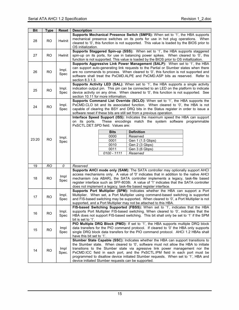
28 RO HwInit
Supports Mechanical Presence Switch (SMPS): When set to ‘1’, the HBA supports mechanical presence switches on its ports for use in hot plug operations. When cleared to ‘0’, this function is not supported. This value is loaded by the BIOS prior to OS initialization.
27 RO HwInit Supports Staggered Spin-up (SSS): When set to ‘1’, the HBA supports staggered spin-up on its ports, for use in balancing power spikes. When cleared to ‘0’, this function is not supported. This value is loaded by the BIOS prior to OS initiallization.
26 RO Impl. Spec
Supports Aggressive Link Power Management (SALP): When set to ‘1’, the HBA can support auto-generating link requests to the Partial or Slumber states when there are no commands to process. When cleared to ‘0’, this function is not supported and software shall treat the PxCMD.ALPE and PxCMD.ASP bits as reserved. Refer to section 8.3.1.3.
25 RO Impl. Spec
Supports Activity LED (SAL): When set to ‘1’, the HBA supports a single activity indication output pin. This pin can be connected to an LED on the platform to indicate device activity on any drive. When cleared to ‘0’, this function is not supported. See section 10.11 for more information.
24 RO Impl. Spec
Supports Command List Override (SCLO): When set to ‘1’, the HBA supports the PxCMD.CLO bit and its associated function. When cleared to ‘0’, the HBA is not capable of clearing the BSY and DRQ bits in the Status register in order to issue a software reset if these bits are still set from a previous operation.
23:20 RO Impl. Spec
Interface Speed Support (ISS): Indicates the maximum speed the HBA can support on its ports. These encodings match the system software programmable PxSCTL.DET.SPD field. Values are:
Bits Definition 0000 Reserved 0001 Gen 1 (1.5 Gbps) 0010 Gen 2 (3 Gbps) 0011 Gen 3 (6 Gbps)
0100 - 1111 Reserved
19 RO 0 Reserved
18 RO Impl Spec
Supports AHCI mode only (SAM): The SATA controller may optionally support AHCI access mechanisms only. A value of '0' indicates that in addition to the native AHCI mechanism (via ABAR), the SATA controller implements a legacy, task-file based register interface such as SFF-8038i. A value of '1' indicates that the SATA controller does not implement a legacy, task-file based register interface.
17 RO Impl. Spec
Supports Port Multiplier (SPM): Indicates whether the HBA can support a Port Multiplier. When set, a Port Multiplier using command-based switching is supported and FIS-based switching may be supported. When cleared to ‘0’, a Port Multiplier is not supported, and a Port Multiplier may not be attached to this HBA.
16 RO Impl. Spec
FIS-based Switching Supported (FBSS): When set to ‘1’, indicates that the HBA supports Port Multiplier FIS-based switching. When cleared to ‘0’, indicates that the HBA does not support FIS-based switching. This bit shall only be set to ‘1’ if the SPM bit is set to ‘1’.
15 RO Impl Spec
PIO Multiple DRQ Block (PMD): If set to ‘1’, the HBA supports multiple DRQ block data transfers for the PIO command protocol. If cleared to ‘0’ the HBA only supports single DRQ block data transfers for the PIO command protocol. AHCI 1.2 HBAs shall have this bit set to ‘1’.
14 RO Impl Spec.
Slumber State Capable (SSC): Indicates whether the HBA can support transitions to the Slumber state. When cleared to ‘0’, software must not allow the HBA to initiate transitions to the Slumber state via agressive link power management nor the PxCMD.ICC field in each port, and the PxSCTL.IPM field in each port must be programmed to disallow device initiated Slumber requests. When set to ‘1’, HBA and device initiated Slumber requests can be supported.
Revision 1_2.doc Serial ATA AHCI 1.2 Specification
16
Bit Type Reset Description
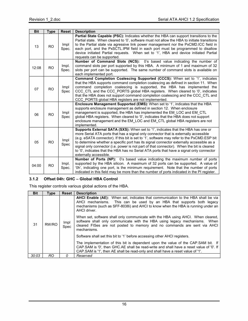
13 RO Impl Spec.
Partial State Capable (PSC): Indicates whether the HBA can support transitions to the Partial state. When cleared to ‘0’, software must not allow the HBA to initiate transitions to the Partial state via agressive link power management nor the PxCMD.ICC field in each port, and the PxSCTL.IPM field in each port must be programmed to disallow device initiated Partial requests. When set to ‘1’, HBA and device initiated Partial requests can be supported.
12:08 RO Impl. Spec.
Number of Command Slots (NCS): 0’s based value indicating the number of command slots per port supported by this HBA. A minimum of 1 and maximum of 32 slots per port can be supported. The same number of command slots is available on each implemented port.
07 RO Impl Spec
Command Completion Coalescing Supported (CCCS): When set to ‘1’, indicates that the HBA supports command completion coalescing as defined in section 11. When command completion coalescing is supported, the HBA has implemented the CCC_CTL and the CCC_PORTS global HBA registers. When cleared to ‘0’, indicates that the HBA does not support command completion coalescing and the CCC_CTL and CCC_PORTS global HBA registers are not implemented.
06 RO Impl Spec
Enclosure Management Supported (EMS): When set to ‘1’, indicates that the HBA supports enclosure management as defined in section 12. When enclosure management is supported, the HBA has implemented the EM_LOC and EM_CTL global HBA registers. When cleared to ‘0’, indicates that the HBA does not support enclosure management and the EM_LOC and EM_CTL global HBA registers are not implemented.
05 RO Impl Spec
Supports External SATA (SXS): When set to ‘1’, indicates that the HBA has one or more Serial ATA ports that has a signal only connector that is externally accessible (e.g. eSATA connector). If this bit is set to ‘1’, software may refer to the PxCMD.ESP bit to determine whether a specific port has its signal connector externally accessible as a signal only connector (i.e. power is not part of that connector). When the bit is cleared to ‘0’, indicates that the HBA has no Serial ATA ports that have a signal only connector externally accessible.
04:00 RO Impl. Spec.
Number of Ports (NP): 0’s based value indicating the maximum number of ports supported by the HBA silicon. A maximum of 32 ports can be supported. A value of ‘0h’, indicating one port, is the minimum requirement. Note that the number of ports indicated in this field may be more than the number of ports indicated in the PI register.
3.1.2 Offset 04h: GHC – Global HBA Control
This register controls various global actions of the HBA.
Bit Type Reset Description
31 RW/RO Impl Spec
AHCI Enable (AE): When set, indicates that communication to the HBA shall be via AHCI mechanisms. This can be used by an HBA that supports both legacy mechanisms (such as SFF-8038i) and AHCI to know when the HBA is running under an AHCI driver.
When set, software shall only communicate with the HBA using AHCI. When cleared, software shall only communicate with the HBA using legacy mechanisms. When cleared FISes are not posted to memory and no commands are sent via AHCI mechanisms.
Software shall set this bit to ‘1’ before accessing other AHCI registers.
The implementation of this bit is dependent upon the value of the CAP.SAM bit. If CAP.SAM is '0', then GHC.AE shall be read-write and shall have a reset value of '0'. If CAP.SAM is '1', then AE shall be read-only and shall have a reset value of '1'.
30:03 RO 0 Reserved
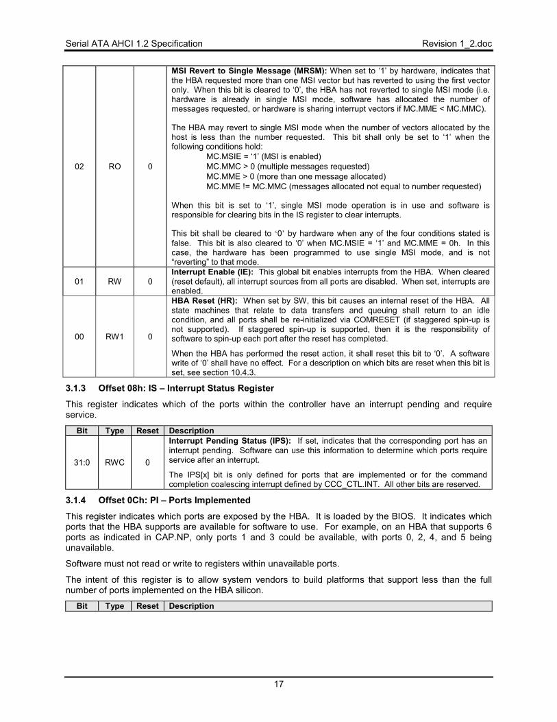
Serial ATA AHCI 1.2 Specification Revision 1_2.doc
17
02 RO 0
MSI Revert to Single Message (MRSM): When set to ‘1’ by hardware, indicates that the HBA requested more than one MSI vector but has reverted to using the first vector only. When this bit is cleared to ‘0’, the HBA has not reverted to single MSI mode (i.e. hardware is already in single MSI mode, software has allocated the number of messages requested, or hardware is sharing interrupt vectors if MC.MME < MC.MMC). The HBA may revert to single MSI mode when the number of vectors allocated by the host is less than the number requested. This bit shall only be set to ‘1’ when the following conditions hold:
• MC.MSIE = ‘1’ (MSI is enabled) • MC.MMC > 0 (multiple messages requested) • MC.MME > 0 (more than one message allocated) • MC.MME != MC.MMC (messages allocated not equal to number requested)
When this bit is set to ‘1’, single MSI mode operation is in use and software is responsible for clearing bits in the IS register to clear interrupts. This bit shall be cleared to ‘0’ by hardware when any of the four conditions stated is false. This bit is also cleared to ‘0’ when MC.MSIE = ‘1’ and MC.MME = 0h. In this case, the hardware has been programmed to use single MSI mode, and is not “reverting” to that mode.
01 RW 0 Interrupt Enable (IE): This global bit enables interrupts from the HBA. When cleared (reset default), all interrupt sources from all ports are disabled. When set, interrupts are enabled.
00 RW1 0
HBA Reset (HR): When set by SW, this bit causes an internal reset of the HBA. All state machines that relate to data transfers and queuing shall return to an idle condition, and all ports shall be re-initialized via COMRESET (if staggered spin-up is not supported). If staggered spin-up is supported, then it is the responsibility of software to spin-up each port after the reset has completed.
When the HBA has performed the reset action, it shall reset this bit to ‘0’. A software write of ‘0’ shall have no effect. For a description on which bits are reset when this bit is set, see section 10.4.3.
3.1.3 Offset 08h: IS – Interrupt Status Register
This register indicates which of the ports within the controller have an interrupt pending and require service.
Bit Type Reset Description
31:0 RWC 0
Interrupt Pending Status (IPS): If set, indicates that the corresponding port has an interrupt pending. Software can use this information to determine which ports require service after an interrupt.
The IPS[x] bit is only defined for ports that are implemented or for the command completion coalescing interrupt defined by CCC_CTL.INT. All other bits are reserved.
3.1.4 Offset 0Ch: PI – Ports Implemented
This register indicates which ports are exposed by the HBA. It is loaded by the BIOS. It indicates which ports that the HBA supports are available for software to use. For example, on an HBA that supports 6 ports as indicated in CAP.NP, only ports 1 and 3 could be available, with ports 0, 2, 4, and 5 being unavailable.
Software must not read or write to registers within unavailable ports.
The intent of this register is to allow system vendors to build platforms that support less than the full number of ports implemented on the HBA silicon.
Bit Type Reset Description

Revision 1_2.doc Serial ATA AHCI 1.2 Specification
18
31:0 RO HwInit
Port Implemented (PI): This register is bit significant. If a bit is set to ‘1’, the corresponding port is available for software to use. If a bit is cleared to ‘0’, the port is not available for software to use. The maximum number of bits set to ‘1’ shall not exceed CAP.NP + 1, although the number of bits set in this register may be fewer than CAP.NP + 1. At least one bit shall be set to ‘1’.
3.1.5 Offset 10h: VS – AHCI Version
This register indicates the major and minor version of the AHCI specification that the HBA implementation supports. The upper two bytes represent the major version number, and the lower two bytes represent the minor version number. Example: Version 3.12 would be represented as 00030102h. Three versions of the specification are valid: 0.95, 1.0, 1.1, and 1.2.
3.1.5.1 VS Value for 0.95 Compliant HBAs Bit Type Reset Description
31:16 RO 0000h Major Version Number (MJR): Indicates the major version is “0” 15:00 RO 0905h Minor Version Number (MNR): Indicates the minor version is “95”.
3.1.5.2 VS Value for 1.0 Compliant HBAs Bit Type Reset Description
31:16 RO 0001h Major Version Number (MJR): Indicates the major version is “1” 15:00 RO 0000h Minor Version Number (MNR): Indicates the minor version is “0”.
3.1.5.3 VS Value for 1.1 Compliant HBAs Bit Type Reset Description
31:16 RO 0001h Major Version Number (MJR): Indicates the major version is “1” 15:00 RO 0100h Minor Version Number (MNR): Indicates the minor version is “10”.
3.1.5.4 VS Value for 1.2 Compliant HBAs Bit Type Reset Description
31:16 RO 0001h Major Version Number (MJR): Indicates the major version is “1” 15:00 RO 0200h Minor Version Number (MNR): Indicates the minor version is “20”.
3.1.6 Offset 14h: CCC_CTL – Command Completion Coalescing Control
The command completion coalescing control register is used to configure the command completion coalescing feature for the entire HBA.
Implementation Note: HBA state variables (examples include hCccComplete and hCccTimer) are used to describe the required externally visible behavior. Implementations are not required to have internal state values that directly correspond to these variables.
Bit Type Reset Description
31:16 RW 1
Timeout Value (TV): The timeout value is specified in 1 millisecond intervals. The timer accuracy shall be within 5%. hCccTimer is loaded with this timeout value. hCccTimer is only decremented when commands are outstanding on selected ports, as defined in section 11.2. The HBA will signal a CCC interrupt when hCccTimer has decremented to ‘0’. hCccTimer is reset to the timeout value on the assertion of each CCC interrupt. A timeout value of ‘0’ is reserved.
15:8 RW 1
Command Completions (CC): Specifies the number of command completions that are necessary to cause a CCC interrupt. The HBA has an internal command completion counter, hCccComplete. hCccComplete is incremented by one each time a selected port has a command completion. When hCccComplete is equal to the command completions value, a CCC interrupt is signaled. The internal command completion counter is reset to ‘0’ on the assertion of each CCC interrupt. A value of ‘0’ for this field shall disable CCC interrupts being generated based on the number of commands completed, i.e. CCC interrupts are only generated based on the timer in this case.
7:3 RO Impl Spec
Interrupt (INT): Specifies the interrupt used by the CCC feature. This interrupt must be marked as unused in the Ports Implemented (PI) register by the corresponding bit being set to ‘0’. Thus, the CCC interrupt corresponds to the interrupt for an unimplemented port on the controller. When a CCC interrupt occurs, the IS.IPS[INT] bit shall be asserted to ‘1’. This field also specifies the interrupt vector used for MSI.
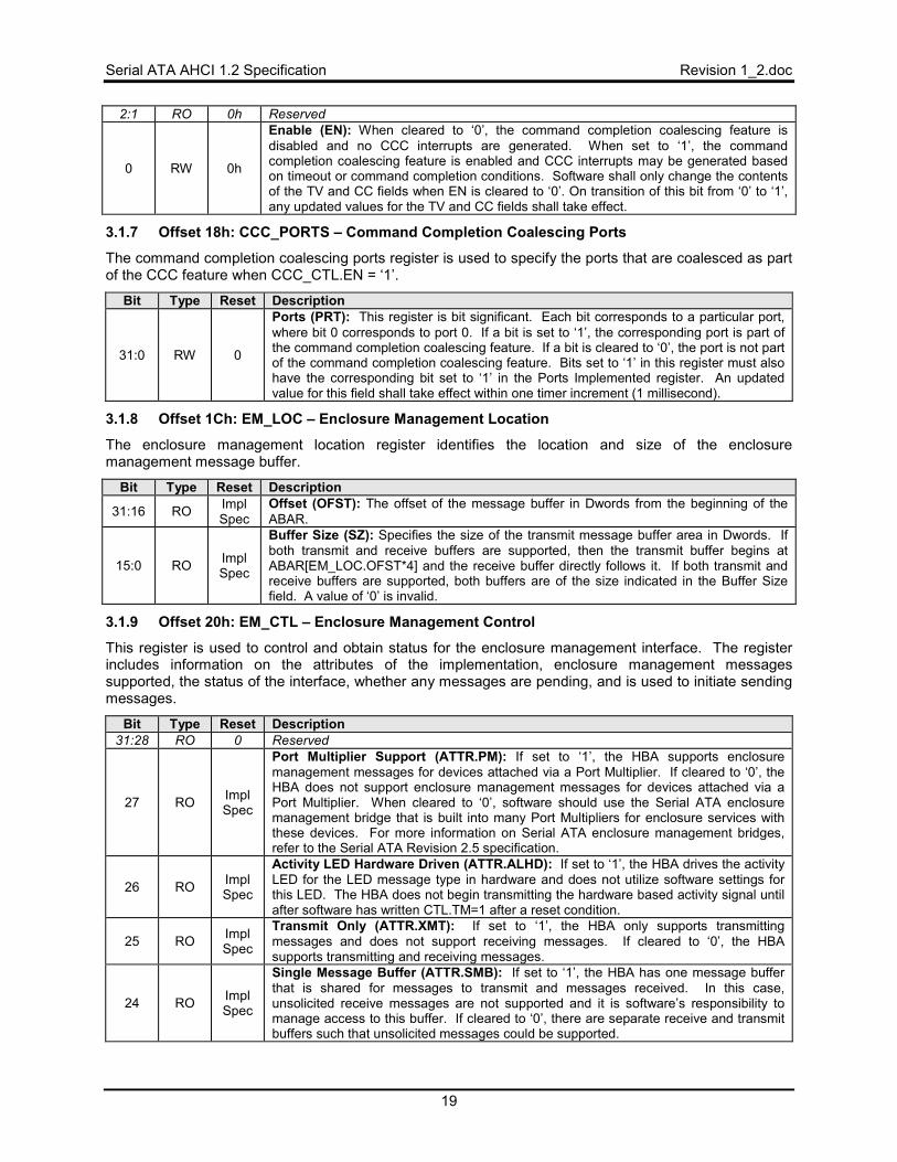
Serial ATA AHCI 1.2 Specification Revision 1_2.doc
19
2:1 RO 0h Reserved
0 RW 0h
Enable (EN): When cleared to ‘0’, the command completion coalescing feature is disabled and no CCC interrupts are generated. When set to ‘1’, the command completion coalescing feature is enabled and CCC interrupts may be generated based on timeout or command completion conditions. Software shall only change the contents of the TV and CC fields when EN is cleared to ‘0’. On transition of this bit from ‘0’ to ‘1’, any updated values for the TV and CC fields shall take effect.
3.1.7 Offset 18h: CCC_PORTS – Command Completion Coalescing Ports
The command completion coalescing ports register is used to specify the ports that are coalesced as part of the CCC feature when CCC_CTL.EN = ‘1’.
Bit Type Reset Description
31:0 RW 0
Ports (PRT): This register is bit significant. Each bit corresponds to a particular port, where bit 0 corresponds to port 0. If a bit is set to ‘1’, the corresponding port is part of the command completion coalescing feature. If a bit is cleared to ‘0’, the port is not part of the command completion coalescing feature. Bits set to ‘1’ in this register must also have the corresponding bit set to ‘1’ in the Ports Implemented register. An updated value for this field shall take effect within one timer increment (1 millisecond).
3.1.8 Offset 1Ch: EM_LOC – Enclosure Management Location
The enclosure management location register identifies the location and size of the enclosure management message buffer.
Bit Type Reset Description
31:16 RO Impl Spec
Offset (OFST): The offset of the message buffer in Dwords from the beginning of the ABAR.
15:0 RO Impl Spec
Buffer Size (SZ): Specifies the size of the transmit message buffer area in Dwords. If both transmit and receive buffers are supported, then the transmit buffer begins at ABAR[EM_LOC.OFST*4] and the receive buffer directly follows it. If both transmit and receive buffers are supported, both buffers are of the size indicated in the Buffer Size field. A value of ‘0’ is invalid.
3.1.9 Offset 20h: EM_CTL – Enclosure Management Control
This register is used to control and obtain status for the enclosure management interface. The register includes information on the attributes of the implementation, enclosure management messages supported, the status of the interface, whether any messages are pending, and is used to initiate sending messages.
Bit Type Reset Description 31:28 RO 0 Reserved
27 RO Impl Spec
Port Multiplier Support (ATTR.PM): If set to ‘1’, the HBA supports enclosure management messages for devices attached via a Port Multiplier. If cleared to ‘0’, the HBA does not support enclosure management messages for devices attached via a Port Multiplier. When cleared to ‘0’, software should use the Serial ATA enclosure management bridge that is built into many Port Multipliers for enclosure services with these devices. For more information on Serial ATA enclosure management bridges, refer to the Serial ATA Revision 2.5 specification.
26 RO Impl Spec
Activity LED Hardware Driven (ATTR.ALHD): If set to ‘1’, the HBA drives the activity LED for the LED message type in hardware and does not utilize software settings for this LED. The HBA does not begin transmitting the hardware based activity signal until after software has written CTL.TM=1 after a reset condition.
25 RO Impl Spec
Transmit Only (ATTR.XMT): If set to ‘1’, the HBA only supports transmitting messages and does not support receiving messages. If cleared to ‘0’, the HBA supports transmitting and receiving messages.
24 RO Impl Spec
Single Message Buffer (ATTR.SMB): If set to ‘1’, the HBA has one message buffer that is shared for messages to transmit and messages received. In this case, unsolicited receive messages are not supported and it is software’s responsibility to manage access to this buffer. If cleared to ‘0’, there are separate receive and transmit buffers such that unsolicited messages could be supported.
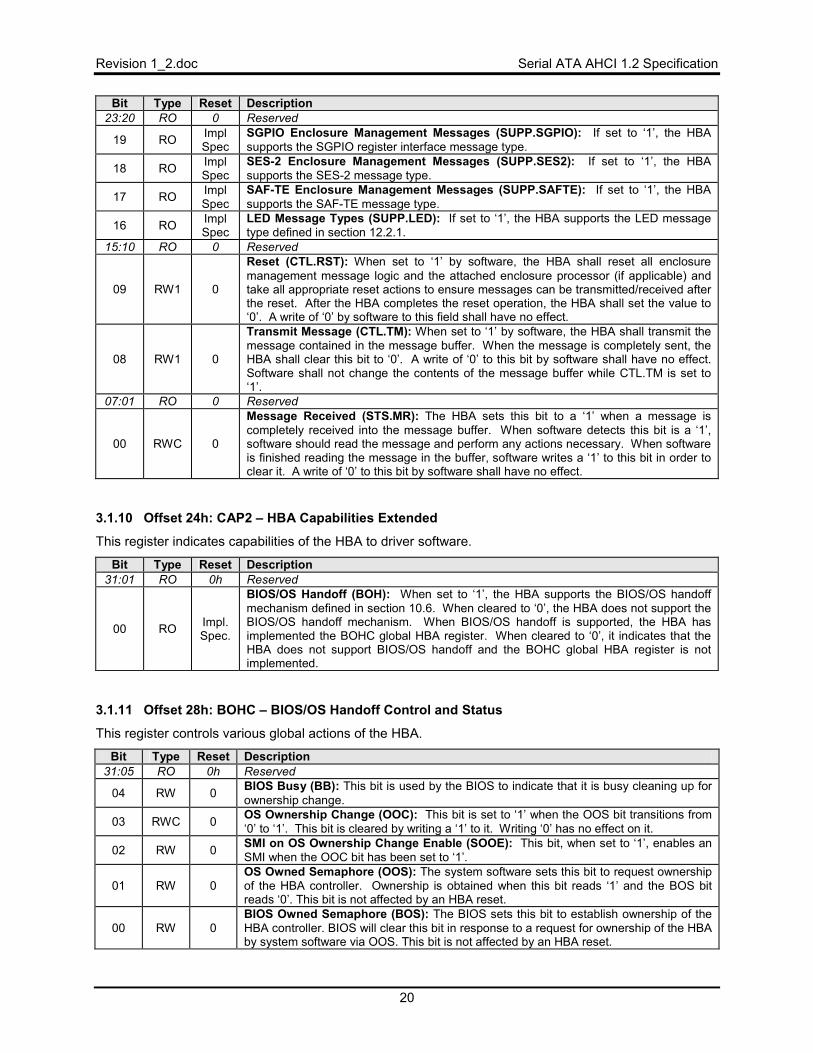
Revision 1_2.doc Serial ATA AHCI 1.2 Specification
20
Bit Type Reset Description 23:20 RO 0 Reserved
19 RO Impl Spec
SGPIO Enclosure Management Messages (SUPP.SGPIO): If set to ‘1’, the HBA supports the SGPIO register interface message type.
18 RO Impl Spec
SES-2 Enclosure Management Messages (SUPP.SES2): If set to ‘1’, the HBA supports the SES-2 message type.
17 RO Impl Spec
SAF-TE Enclosure Management Messages (SUPP.SAFTE): If set to ‘1’, the HBA supports the SAF-TE message type.
16 RO Impl Spec
LED Message Types (SUPP.LED): If set to ‘1’, the HBA supports the LED message type defined in section 12.2.1.
15:10 RO 0 Reserved
09 RW1 0
Reset (CTL.RST): When set to ‘1’ by software, the HBA shall reset all enclosure management message logic and the attached enclosure processor (if applicable) and take all appropriate reset actions to ensure messages can be transmitted/received after the reset. After the HBA completes the reset operation, the HBA shall set the value to ‘0’. A write of ‘0’ by software to this field shall have no effect.
08 RW1 0
Transmit Message (CTL.TM): When set to ‘1’ by software, the HBA shall transmit the message contained in the message buffer. When the message is completely sent, the HBA shall clear this bit to ‘0’. A write of ‘0’ to this bit by software shall have no effect. Software shall not change the contents of the message buffer while CTL.TM is set to ‘1’.
07:01 RO 0 Reserved
00 RWC 0
Message Received (STS.MR): The HBA sets this bit to a ‘1’ when a message is completely received into the message buffer. When software detects this bit is a ‘1’, software should read the message and perform any actions necessary. When software is finished reading the message in the buffer, software writes a ‘1’ to this bit in order to clear it. A write of ‘0’ to this bit by software shall have no effect.
3.1.10 Offset 24h: CAP2 – HBA Capabilities Extended
This register indicates capabilities of the HBA to driver software.
Bit Type Reset Description 31:01 RO 0h Reserved
00 RO Impl. Spec.
BIOS/OS Handoff (BOH): When set to ‘1’, the HBA supports the BIOS/OS handoff mechanism defined in section 10.6. When cleared to ‘0’, the HBA does not support the BIOS/OS handoff mechanism. When BIOS/OS handoff is supported, the HBA has implemented the BOHC global HBA register. When cleared to ‘0’, it indicates that the HBA does not support BIOS/OS handoff and the BOHC global HBA register is not implemented.
3.1.11 Offset 28h: BOHC – BIOS/OS Handoff Control and Status
This register controls various global actions of the HBA.
Bit Type Reset Description 31:05 RO 0h Reserved
04 RW 0 BIOS Busy (BB): This bit is used by the BIOS to indicate that it is busy cleaning up for ownership change.
03 RWC 0 OS Ownership Change (OOC): This bit is set to ‘1’ when the OOS bit transitions from ‘0’ to ‘1’. This bit is cleared by writing a ‘1’ to it. Writing ‘0’ has no effect on it.
02 RW 0 SMI on OS Ownership Change Enable (SOOE): This bit, when set to ‘1’, enables an SMI when the OOC bit has been set to ‘1’.
01 RW 0 OS Owned Semaphore (OOS): The system software sets this bit to request ownership of the HBA controller. Ownership is obtained when this bit reads ‘1’ and the BOS bit reads ‘0’. This bit is not affected by an HBA reset.
00 RW 0 BIOS Owned Semaphore (BOS): The BIOS sets this bit to establish ownership of the HBA controller. BIOS will clear this bit in response to a request for ownership of the HBA by system software via OOS. This bit is not affected by an HBA reset.
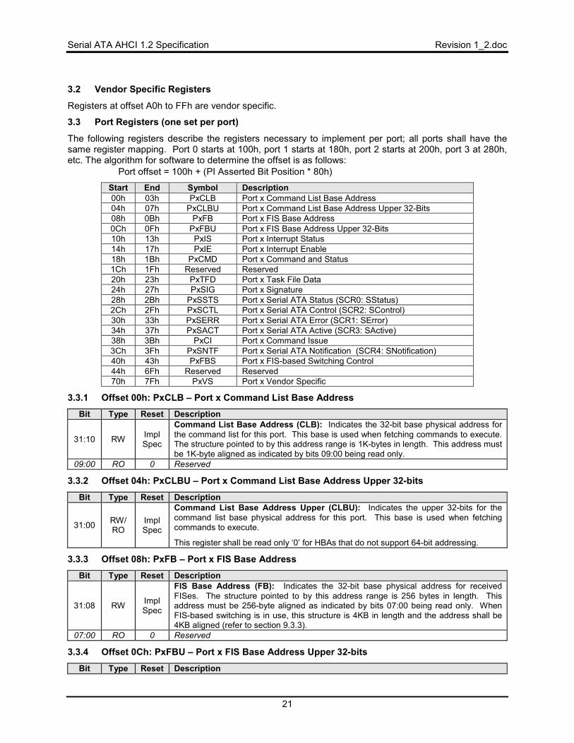
Serial ATA AHCI 1.2 Specification Revision 1_2.doc
21
3.2 Vendor Specific Registers
Registers at offset A0h to FFh are vendor specific.
3.3 Port Registers (one set per port)
The following registers describe the registers necessary to implement per port; all ports shall have the same register mapping. Port 0 starts at 100h, port 1 starts at 180h, port 2 starts at 200h, port 3 at 280h, etc. The algorithm for software to determine the offset is as follows:
• Port offset = 100h + (PI Asserted Bit Position * 80h)
Start End Symbol Description 00h 03h PxCLB Port x Command List Base Address 04h 07h PxCLBU Port x Command List Base Address Upper 32-Bits 08h 0Bh PxFB Port x FIS Base Address 0Ch 0Fh PxFBU Port x FIS Base Address Upper 32-Bits 10h 13h PxIS Port x Interrupt Status 14h 17h PxIE Port x Interrupt Enable 18h 1Bh PxCMD Port x Command and Status 1Ch 1Fh Reserved Reserved 20h 23h PxTFD Port x Task File Data 24h 27h PxSIG Port x Signature 28h 2Bh PxSSTS Port x Serial ATA Status (SCR0: SStatus) 2Ch 2Fh PxSCTL Port x Serial ATA Control (SCR2: SControl) 30h 33h PxSERR Port x Serial ATA Error (SCR1: SError) 34h 37h PxSACT Port x Serial ATA Active (SCR3: SActive) 38h 3Bh PxCI Port x Command Issue 3Ch 3Fh PxSNTF Port x Serial ATA Notification (SCR4: SNotification) 40h 43h PxFBS Port x FIS-based Switching Control 44h 6Fh Reserved Reserved 70h 7Fh PxVS Port x Vendor Specific
3.3.1 Offset 00h: PxCLB – Port x Command List Base Address Bit Type Reset Description
31:10 RW Impl Spec
Command List Base Address (CLB): Indicates the 32-bit base physical address for the command list for this port. This base is used when fetching commands to execute. The structure pointed to by this address range is 1K-bytes in length. This address must be 1K-byte aligned as indicated by bits 09:00 being read only.
09:00 RO 0 Reserved
3.3.2 Offset 04h: PxCLBU – Port x Command List Base Address Upper 32-bits
Bit Type Reset Description
31:00 RW/ RO
Impl Spec
Command List Base Address Upper (CLBU): Indicates the upper 32-bits for the command list base physical address for this port. This base is used when fetching commands to execute.
This register shall be read only ‘0’ for HBAs that do not support 64-bit addressing.
3.3.3 Offset 08h: PxFB – Port x FIS Base Address Bit Type Reset Description
31:08 RW Impl Spec
FIS Base Address (FB): Indicates the 32-bit base physical address for received FISes. The structure pointed to by this address range is 256 bytes in length. This address must be 256-byte aligned as indicated by bits 07:00 being read only. When FIS-based switching is in use, this structure is 4KB in length and the address shall be 4KB aligned (refer to section 9.3.3).
07:00 RO 0 Reserved
3.3.4 Offset 0Ch: PxFBU – Port x FIS Base Address Upper 32-bits
Bit Type Reset Description
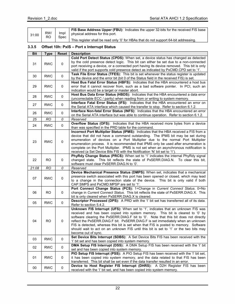
Revision 1_2.doc Serial ATA AHCI 1.2 Specification
22
31:00 RW/ RO
Impl Spec
FIS Base Address Upper (FBU): Indicates the upper 32-bits for the received FIS base physical address for this port.
This register shall be read only ‘0’ for HBAs that do not support 64-bit addressing.
3.3.5 Offset 10h: PxIS – Port x Interrupt Status
Bit Type Reset Description
31 RWC 0
Cold Port Detect Status (CPDS): When set, a device status has changed as detected by the cold presence detect logic. This bit can either be set due to a non-connected port receiving a device, or a connected port having its device removed. This bit is only valid if the port supports cold presence detect as indicated by PxCMD.CPD set to ‘1’.
30 RWC 0 Task File Error Status (TFES): This bit is set whenever the status register is updated by the device and the error bit (bit 0 of the Status field in the received FIS) is set.
29 RWC 0 Host Bus Fatal Error Status (HBFS): Indicates that the HBA encountered a host bus error that it cannot recover from, such as a bad software pointer. In PCI, such an indication would be a target or master abort.
28 RWC 0 Host Bus Data Error Status (HBDS): Indicates that the HBA encountered a data error (uncorrectable ECC / parity) when reading from or writing to system memory.
27 RWC 0 Interface Fatal Error Status (IFS): Indicates that the HBA encountered an error on the Serial ATA interface which caused the transfer to stop. Refer to section 6.1.2.
26 RWC 0 Interface Non-fatal Error Status (INFS): Indicates that the HBA encountered an error on the Serial ATA interface but was able to continue operation. Refer to section 6.1.2.
25 RO 0 Reserved
24 RWC 0 Overflow Status (OFS): Indicates that the HBA received more bytes from a device than was specified in the PRD table for the command.
23 RWC 0
Incorrect Port Multiplier Status (IPMS): Indicates that the HBA received a FIS from a device that did not have a command outstanding. The IPMS bit may be set during enumeration of devices on a Port Multiplier due to the normal Port Multiplier enumeration process. It is recommended that IPMS only be used after enumeration is complete on the Port Multiplier. IPMS is not set when an asynchronous notification is received (a Set Device Bits FIS with the Notification ‘N’ bit set to ‘1’).
22 RO 0 PhyRdy Change Status (PRCS): When set to ‘1’ indicates the internal PhyRdy signal changed state. This bit reflects the state of PxSERR.DIAG.N. To clear this bit, software must clear PxSERR.DIAG.N to ‘0’.
21:08 RO 0 Reserved
07 RWC 0
Device Mechanical Presence Status (DMPS): When set, indicates that a mechanical presence switch associated with this port has been opened or closed, which may lead to a change in the connection state of the device. This bit is only valid if both CAP.SMPS and PxCMD.MPSP are set to ‘1’.
06 RO 0 Port Connect Change Status (PCS): 1=Change in Current Connect Status. 0=No change in Current Connect Status. This bit reflects the state of PxSERR.DIAG.X. This bit is only cleared when PxSERR.DIAG.X is cleared.
05 RWC 0 Descriptor Processed (DPS): A PRD with the ‘I’ bit set has transferred all of its data. Refer to section 5.4.2.
04 RO 0
Unknown FIS Interrupt (UFS): When set to ‘1’, indicates that an unknown FIS was received and has been copied into system memory. This bit is cleared to ‘0’ by software clearing the PxSERR.DIAG.F bit to ‘0’. Note that this bit does not directly reflect the PxSERR.DIAG.F bit. PxSERR.DIAG.F is set immediately when an unknown FIS is detected, whereas this bit is set when that FIS is posted to memory. Software should wait to act on an unknown FIS until this bit is set to ‘1’ or the two bits may become out of sync.
03 RWC 0 Set Device Bits Interrupt (SDBS): A Set Device Bits FIS has been received with the ‘I’ bit set and has been copied into system memory.
02 RWC 0 DMA Setup FIS Interrupt (DSS): A DMA Setup FIS has been received with the ‘I’ bit set and has been copied into system memory.
01 RWC 0 PIO Setup FIS Interrupt (PSS): A PIO Setup FIS has been received with the ‘I’ bit set, it has been copied into system memory, and the data related to that FIS has been transferred. This bit shall be set even if the data transfer resulted in an error.
00 RWC 0 Device to Host Register FIS Interrupt (DHRS): A D2H Register FIS has been received with the ‘I’ bit set, and has been copied into system memory.
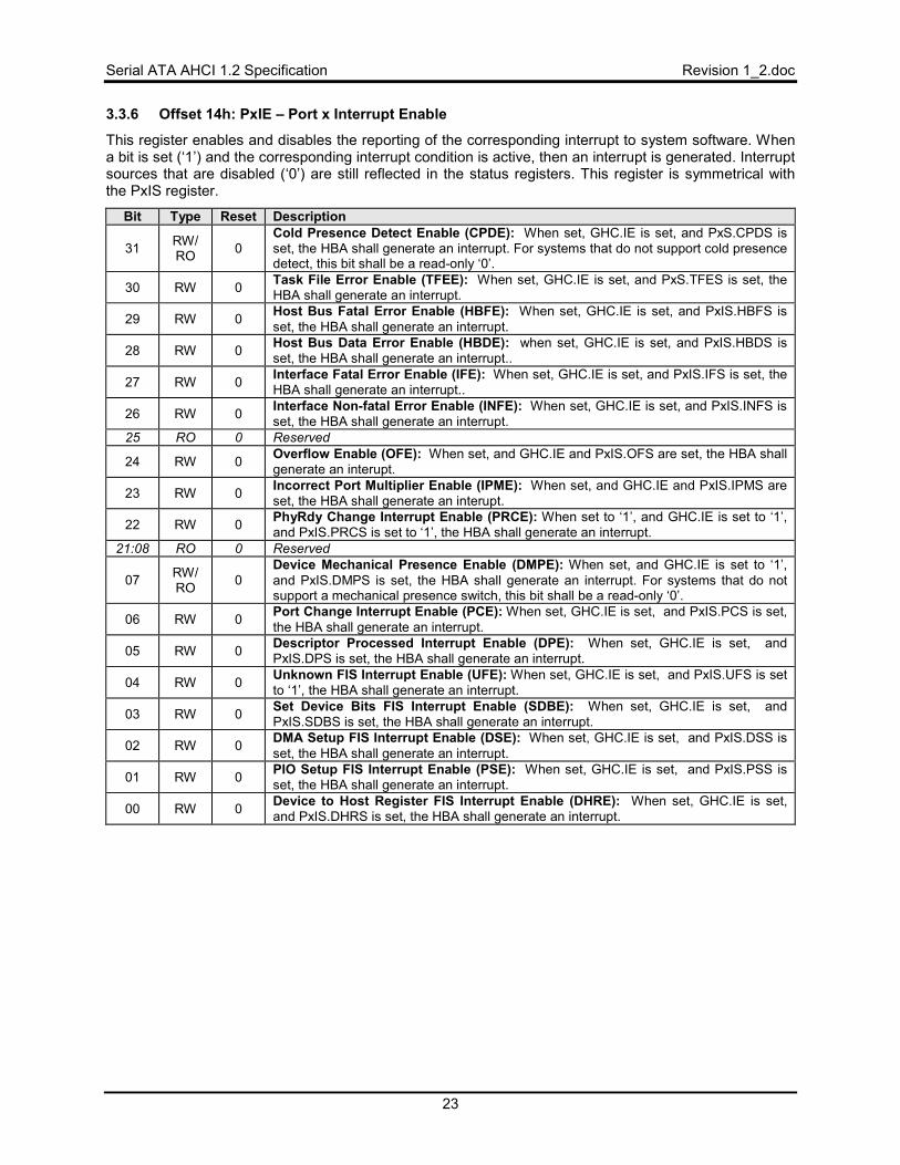
Serial ATA AHCI 1.2 Specification Revision 1_2.doc
23
3.3.6 Offset 14h: PxIE – Port x Interrupt Enable
This register enables and disables the reporting of the corresponding interrupt to system software. When a bit is set (‘1’) and the corresponding interrupt condition is active, then an interrupt is generated. Interrupt sources that are disabled (‘0’) are still reflected in the status registers. This register is symmetrical with the PxIS register.
Bit Type Reset Description
31 RW/ RO 0
Cold Presence Detect Enable (CPDE): When set, GHC.IE is set, and PxS.CPDS is set, the HBA shall generate an interrupt. For systems that do not support cold presence detect, this bit shall be a read-only ‘0’.
30 RW 0 Task File Error Enable (TFEE): When set, GHC.IE is set, and PxS.TFES is set, the HBA shall generate an interrupt.
29 RW 0 Host Bus Fatal Error Enable (HBFE): When set, GHC.IE is set, and PxIS.HBFS is set, the HBA shall generate an interrupt.
28 RW 0 Host Bus Data Error Enable (HBDE): when set, GHC.IE is set, and PxIS.HBDS is set, the HBA shall generate an interrupt..
27 RW 0 Interface Fatal Error Enable (IFE): When set, GHC.IE is set, and PxIS.IFS is set, the HBA shall generate an interrupt..
26 RW 0 Interface Non-fatal Error Enable (INFE): When set, GHC.IE is set, and PxIS.INFS is set, the HBA shall generate an interrupt.
25 RO 0 Reserved
24 RW 0 Overflow Enable (OFE): When set, and GHC.IE and PxIS.OFS are set, the HBA shall generate an interupt.
23 RW 0 Incorrect Port Multiplier Enable (IPME): When set, and GHC.IE and PxIS.IPMS are set, the HBA shall generate an interupt.
22 RW 0 PhyRdy Change Interrupt Enable (PRCE): When set to ‘1’, and GHC.IE is set to ‘1’, and PxIS.PRCS is set to ‘1’, the HBA shall generate an interrupt.
21:08 RO 0 Reserved
07 RW/ RO 0
Device Mechanical Presence Enable (DMPE): When set, and GHC.IE is set to ‘1’, and PxIS.DMPS is set, the HBA shall generate an interrupt. For systems that do not support a mechanical presence switch, this bit shall be a read-only ‘0’.
06 RW 0 Port Change Interrupt Enable (PCE): When set, GHC.IE is set, and PxIS.PCS is set, the HBA shall generate an interrupt.
05 RW 0 Descriptor Processed Interrupt Enable (DPE): When set, GHC.IE is set, and PxIS.DPS is set, the HBA shall generate an interrupt.
04 RW 0 Unknown FIS Interrupt Enable (UFE): When set, GHC.IE is set, and PxIS.UFS is set to ‘1’, the HBA shall generate an interrupt.
03 RW 0 Set Device Bits FIS Interrupt Enable (SDBE): When set, GHC.IE is set, and PxIS.SDBS is set, the HBA shall generate an interrupt.
02 RW 0 DMA Setup FIS Interrupt Enable (DSE): When set, GHC.IE is set, and PxIS.DSS is set, the HBA shall generate an interrupt.
01 RW 0 PIO Setup FIS Interrupt Enable (PSE): When set, GHC.IE is set, and PxIS.PSS is set, the HBA shall generate an interrupt.
00 RW 0 Device to Host Register FIS Interrupt Enable (DHRE): When set, GHC.IE is set, and PxIS.DHRS is set, the HBA shall generate an interrupt.
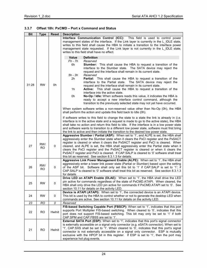
Revision 1_2.doc Serial ATA AHCI 1.2 Specification
24
3.3.7 Offset 18h: PxCMD – Port x Command and Status
Bit Type Reset Description
31:28 RW 0h
Interface Communication Control (ICC): This field is used to control power management states of the interface. If the Link layer is currently in the L_IDLE state, writes to this field shall cause the HBA to initiate a transition to the interface power management state requested. If the Link layer is not currently in the L_IDLE state, writes to this field shall have no effect.
Value Definition Fh - 7h Reserved
6h Slumber: This shall cause the HBA to request a transition of the interface to the Slumber state. The SATA device may reject the request and the interface shall remain in its current state.
5h - 3h Reserved 2h Partial: This shall cause the HBA to request a transition of the
interface to the Partial state. The SATA device may reject the request and the interface shall remain in its current state.
1h Active: This shall cause the HBA to request a transition of the interface into the active state.
0h No-Op / Idle: When software reads this value, it indicates the HBA is ready to accept a new interface control command, although the transition to the previously selected state may not yet have occurred.
When system software writes a non-reserved value other than No-Op (0h), the HBA shall perform the action and update this field back to Idle (0h).
If software writes to this field to change the state to a state the link is already in (i.e. interface is in the active state and a request is made to go to the active state), the HBA shall take no action and return this field to Idle. If the interface is in a low power state and software wants to transition to a different low power state, software must first bring the link to active and then initiate the transition to the desired low power state.
27 RW/ RO 0
Aggressive Slumber / Partial (ASP): When set to ‘1’, and ALPE is set, the HBA shall aggressively enter the Slumber state when it clears the PxCI register and the PxSACT register is cleared or when it clears the PxSACT register and PxCI is cleared. When cleared, and ALPE is set, the HBA shall aggressively enter the Partial state when it clears the PxCI register and the PxSACT register is cleared or when it clears the PxSACT register and PxCI is cleared. If CAP.SALP is cleared to ‘0’ software shall treat this bit as reserved. See section 8.3.1.3 for details.
26 RW/ RO 0
Aggressive Link Power Management Enable (ALPE): When set to ‘1’, the HBA shall aggressively enter a lower link power state (Partial or Slumber) based upon the setting of the ASP bit. Software shall only set this bit to ‘1’ if CAP.SALP is set to ‘1’; if CAP.SALP is cleared to ‘0’ software shall treat this bit as reserved. See section 8.3.1.3 for details.
25 RW 0
Drive LED on ATAPI Enable (DLAE): When set to ‘1’, the HBA shall drive the LED pin active for commands regardless of the state of PxCMD.ATAPI. When cleared, the HBA shall only drive the LED pin active for commands if PxCMD.ATAPI set to ‘0’. See section 10.11 for details on the activity LED.
24 RW 0 Device is ATAPI (ATAPI): When set to ‘1’, the connected device is an ATAPI device. This bit is used by the HBA to control whether or not to generate the desktop LED when commands are active. See section 10.11 for details on the activity LED.
23 RO 0 Reserved
22 RO HwInit
FIS-based Switching Capable Port (FBSCP): When set to ‘1’, indicates that this port supports Port Multiplier FIS-based switching. When cleared to ‘0’, indicates that this port does not support FIS-based switching. This bit may only be set to ‘1’ if both CAP.SPM and CAP.FBSS are set to ‘1’.
21 RO HwInit
External SATA Port (ESP): When set to '1', indicates that this port’s signal connector is externally accessible on a signal only connector (e.g. eSATA connector). When set to '1', CAP.SXS shall be set to '1'. When cleared to ‘0’, indicates that this port’s signal connector is not externally accessible on a signal only connector. ESP is mutually exclusive with the HPCP bit in this register. If ESP is set to ‘1’, then the port may experience hot plug events.
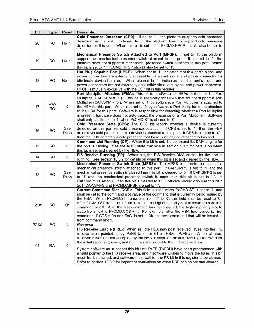
Serial ATA AHCI 1.2 Specification Revision 1_2.doc
25
Bit Type Reset Description
20 RO HwInit
Cold Presence Detection (CPD): If set to ‘1’, the platform supports cold presence detection on this port. If cleared to ‘0’, the platform does not support cold presence detection on this port. When this bit is set to ‘1’, PxCMD.HPCP should also be set to ‘1’.
19 RO HwInit
Mechanical Presence Switch Attached to Port (MPSP): If set to ‘1’, the platform supports an mechanical presence switch attached to this port. If cleared to ‘0’, the platform does not support a mechanical presence switch attached to this port. When this bit is set to ‘1’, PxCMD.HPCP should also be set to ‘1’.
18 RO HwInit
Hot Plug Capable Port (HPCP): When set to ‘1’, indicates that this port’s signal and power connectors are externally accessible via a joint signal and power connector for blindmate device hot plug. When cleared to ‘0’, indicates that this port’s signal and power connectors are not externally accessible via a joint signal and power connector. HPCP is mutually exclusive with the ESP bit in this register.
17 RW/ RO 0
Port Multiplier Attached (PMA): This bit is read/write for HBAs that support a Port Multiplier (CAP.SPM = ‘1’). This bit is read-only for HBAs that do not support a port Multiplier (CAP.SPM = ‘0’). When set to ‘1’ by software, a Port Multiplier is attached to the HBA for this port. When cleared to ‘0’ by software, a Port Multiplier is not attached to the HBA for this port. Software is responsible for detecting whether a Port Multiplier is present; hardware does not auto-detect the presence of a Port Multiplier. Software shall only set this bit to ‘1’ when PxCMD.ST is cleared to ‘0’.
16 RO See Desc
Cold Presence State (CPS): The CPS bit reports whether a device is currently detected on this port via cold presence detection. If CPS is set to ‘1’, then the HBA detects via cold presence that a device is attached to this port. If CPS is cleared to ‘0’ , then the HBA detects via cold presence that there is no device attached to this port.
15 RO 0 Command List Running (CR): When this bit is set, the command list DMA engine for the port is running. See the AHCI state machine in section 5.3.2 for details on when this bit is set and cleared by the HBA.
14 RO 0 FIS Receive Running (FR): When set, the FIS Receive DMA engine for the port is running. See section 10.3.2 for details on when this bit is set and cleared by the HBA.
13 RO See Desc
Mechanical Presence Switch State (MPSS): The MPSS bit reports the state of a mechanical presence switch attached to this port. If CAP.SMPS is set to ‘1’ and the mechanical presence switch is closed then this bit is cleared to ‘0’. If CAP.SMPS is set to ‘1’ and the mechanical presence switch is open then this bit is set to ‘1’. If CAP.SMPS is set to ‘0’ then this bit is cleared to ‘0’. Software should only use this bit if both CAP.SMPS and PxCMD.MPSP are set to ‘1’.
12:08 RO 0h
Current Command Slot (CCS): This field is valid when PxCMD.ST is set to ‘1’ and shall be set to the command slot value of the command that is currently being issued by the HBA. When PxCMD.ST transitions from ‘1’ to ‘0’, this field shall be reset to ‘0’. After PxCMD.ST transitions from ‘0’ to ‘1’, the highest priority slot to issue from next is command slot 0. After the first command has been issued, the highest priority slot to issue from next is PxCMD.CCS + 1. For example, after the HBA has issued its first command, if CCS = 0h and PxCI is set to 3h, the next command that will be issued is from command slot 1.
07:05 RO 0 Reserved
04 RW 0
FIS Receive Enable (FRE): When set, the HBA may post received FISes into the FIS receive area pointed to by PxFB (and for 64-bit HBAs, PxFBU). When cleared, received FISes are not accepted by the HBA, except for the first D2H register FIS after the initialization sequence, and no FISes are posted to the FIS receive area.
System software must not set this bit until PxFB (PxFBU) have been programmed with a valid pointer to the FIS receive area, and if software wishes to move the base, this bit must first be cleared, and software must wait for the FR bit in this register to be cleared. Refer to section 10.3.2 for important restrictions on when FRE can be set and cleared.
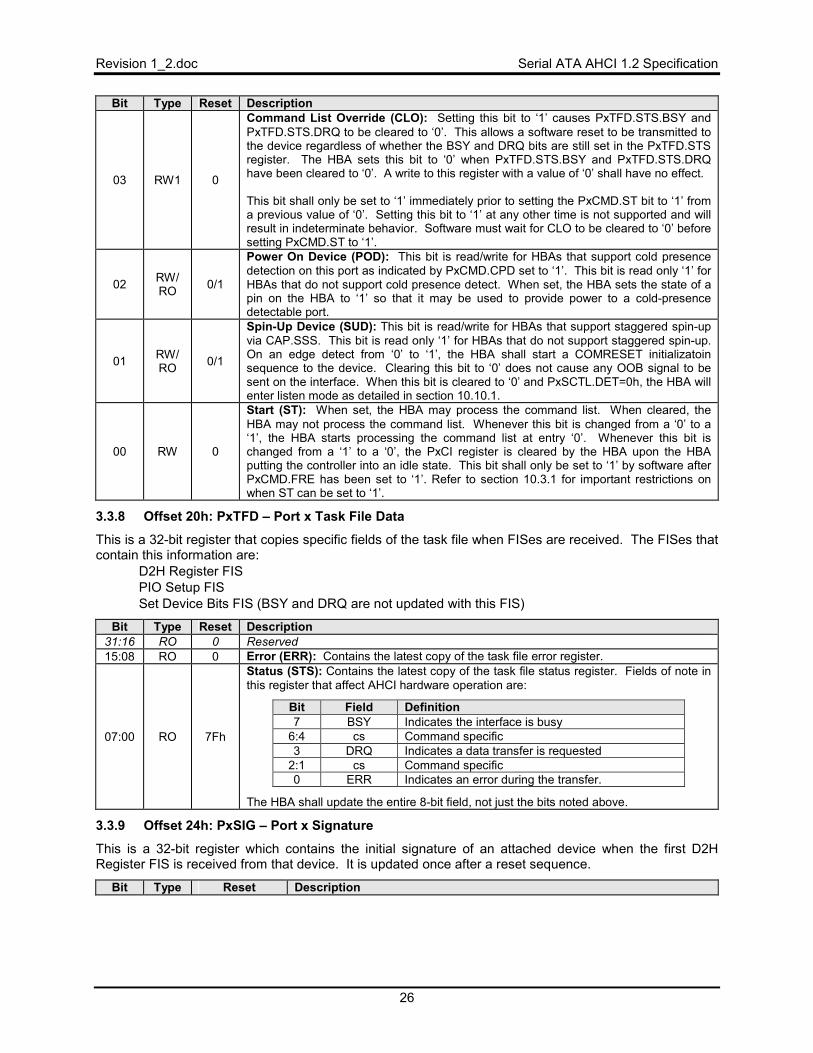
Revision 1_2.doc Serial ATA AHCI 1.2 Specification
26
Bit Type Reset Description
03 RW1 0
Command List Override (CLO): Setting this bit to ‘1’ causes PxTFD.STS.BSY and PxTFD.STS.DRQ to be cleared to ‘0’. This allows a software reset to be transmitted to the device regardless of whether the BSY and DRQ bits are still set in the PxTFD.STS register. The HBA sets this bit to ‘0’ when PxTFD.STS.BSY and PxTFD.STS.DRQ have been cleared to ‘0’. A write to this register with a value of ‘0’ shall have no effect. This bit shall only be set to ‘1’ immediately prior to setting the PxCMD.ST bit to ‘1’ from a previous value of ‘0’. Setting this bit to ‘1’ at any other time is not supported and will result in indeterminate behavior. Software must wait for CLO to be cleared to ‘0’ before setting PxCMD.ST to ‘1’.
02 RW/ RO 0/1
Power On Device (POD): This bit is read/write for HBAs that support cold presence detection on this port as indicated by PxCMD.CPD set to ‘1’. This bit is read only ‘1’ for HBAs that do not support cold presence detect. When set, the HBA sets the state of a pin on the HBA to ‘1’ so that it may be used to provide power to a cold-presence detectable port.
01 RW/ RO 0/1
Spin-Up Device (SUD): This bit is read/write for HBAs that support staggered spin-up via CAP.SSS. This bit is read only ‘1’ for HBAs that do not support staggered spin-up. On an edge detect from ‘0’ to ‘1’, the HBA shall start a COMRESET initializatoin sequence to the device. Clearing this bit to ‘0’ does not cause any OOB signal to be sent on the interface. When this bit is cleared to ‘0’ and PxSCTL.DET=0h, the HBA will enter listen mode as detailed in section 10.10.1.
00 RW 0
Start (ST): When set, the HBA may process the command list. When cleared, the HBA may not process the command list. Whenever this bit is changed from a ‘0’ to a ‘1’, the HBA starts processing the command list at entry ‘0’. Whenever this bit is changed from a ‘1’ to a ‘0’, the PxCI register is cleared by the HBA upon the HBA putting the controller into an idle state. This bit shall only be set to ‘1’ by software after PxCMD.FRE has been set to ‘1’. Refer to section 10.3.1 for important restrictions on when ST can be set to ‘1’.
3.3.8 Offset 20h: PxTFD – Port x Task File Data
This is a 32-bit register that copies specific fields of the task file when FISes are received. The FISes that contain this information are:
• D2H Register FIS • PIO Setup FIS • Set Device Bits FIS (BSY and DRQ are not updated with this FIS)
Bit Type Reset Description 31:16 RO 0 Reserved 15:08 RO 0 Error (ERR): Contains the latest copy of the task file error register.
07:00 RO 7Fh
Status (STS): Contains the latest copy of the task file status register. Fields of note in this register that affect AHCI hardware operation are:
Bit Field Definition 7 BSY Indicates the interface is busy
6:4 cs Command specific 3 DRQ Indicates a data transfer is requested
2:1 cs Command specific 0 ERR Indicates an error during the transfer.
The HBA shall update the entire 8-bit field, not just the bits noted above.
3.3.9 Offset 24h: PxSIG – Port x Signature
This is a 32-bit register which contains the initial signature of an attached device when the first D2H Register FIS is received from that device. It is updated once after a reset sequence.
Bit Type Reset Description
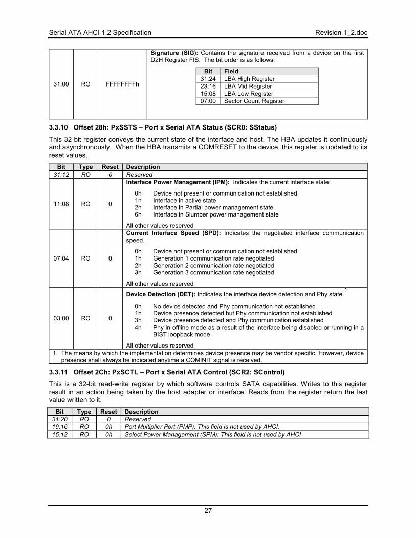
Serial ATA AHCI 1.2 Specification Revision 1_2.doc
27
31:00 RO FFFFFFFFh
Signature (SIG): Contains the signature received from a device on the first D2H Register FIS. The bit order is as follows:
Bit Field 31:24 LBA High Register 23:16 LBA Mid Register 15:08 LBA Low Register 07:00 Sector Count Register
3.3.10 Offset 28h: PxSSTS – Port x Serial ATA Status (SCR0: SStatus)
This 32-bit register conveys the current state of the interface and host. The HBA updates it continuously and asynchronously. When the HBA transmits a COMRESET to the device, this register is updated to its reset values.
Bit Type Reset Description 31:12 RO 0 Reserved
11:08 RO 0
Interface Power Management (IPM): Indicates the current interface state:
0h Device not present or communication not established 1h Interface in active state 2h Interface in Partial power management state 6h Interface in Slumber power management state
All other values reserved
07:04 RO 0
Current Interface Speed (SPD): Indicates the negotiated interface communication speed.
0h Device not present or communication not established 1h Generation 1 communication rate negotiated 2h Generation 2 communication rate negotiated 3h Generation 3 communication rate negotiated
All other values reserved
03:00 RO 0
Device Detection (DET): Indicates the interface device detection and Phy state.1
0h No device detected and Phy communication not established 1h Device presence detected but Phy communication not established 3h Device presence detected and Phy communication established 4h Phy in offline mode as a result of the interface being disabled or running in a
BIST loopback mode
All other values reserved 1. The means by which the implementation determines device presence may be vendor specific. However, device
presence shall always be indicated anytime a COMINIT signal is received.
3.3.11 Offset 2Ch: PxSCTL – Port x Serial ATA Control (SCR2: SControl)
This is a 32-bit read-write register by which software controls SATA capabilities. Writes to this register result in an action being taken by the host adapter or interface. Reads from the register return the last value written to it.
Bit Type Reset Description 31:20 RO 0 Reserved 19:16 RO 0h Port Multiplier Port (PMP): This field is not used by AHCI. 15:12 RO 0h Select Power Management (SPM): This field is not used by AHCI
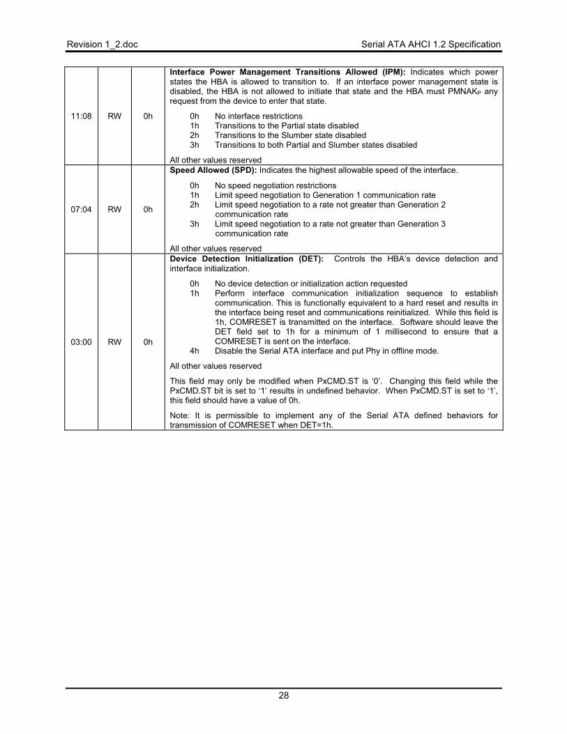
Revision 1_2.doc Serial ATA AHCI 1.2 Specification
28
11:08 RW 0h
Interface Power Management Transitions Allowed (IPM): Indicates which power states the HBA is allowed to transition to. If an interface power management state is disabled, the HBA is not allowed to initiate that state and the HBA must PMNAKP any request from the device to enter that state.
0h No interface restrictions 1h Transitions to the Partial state disabled 2h Transitions to the Slumber state disabled 3h Transitions to both Partial and Slumber states disabled
All other values reserved
07:04 RW 0h
Speed Allowed (SPD): Indicates the highest allowable speed of the interface.
0h No speed negotiation restrictions 1h Limit speed negotiation to Generation 1 communication rate 2h Limit speed negotiation to a rate not greater than Generation 2
communication rate 3h Limit speed negotiation to a rate not greater than Generation 3
communication rate
All other values reserved
03:00 RW 0h
Device Detection Initialization (DET): Controls the HBA’s device detection and interface initialization.
0h No device detection or initialization action requested 1h Perform interface communication initialization sequence to establish
communication. This is functionally equivalent to a hard reset and results in the interface being reset and communications reinitialized. While this field is 1h, COMRESET is transmitted on the interface. Software should leave the DET field set to 1h for a minimum of 1 millisecond to ensure that a COMRESET is sent on the interface.
4h Disable the Serial ATA interface and put Phy in offline mode.
All other values reserved
This field may only be modified when PxCMD.ST is ‘0’. Changing this field while the PxCMD.ST bit is set to ‘1’ results in undefined behavior. When PxCMD.ST is set to ‘1’, this field should have a value of 0h.
Note: It is permissible to implement any of the Serial ATA defined behaviors for transmission of COMRESET when DET=1h.
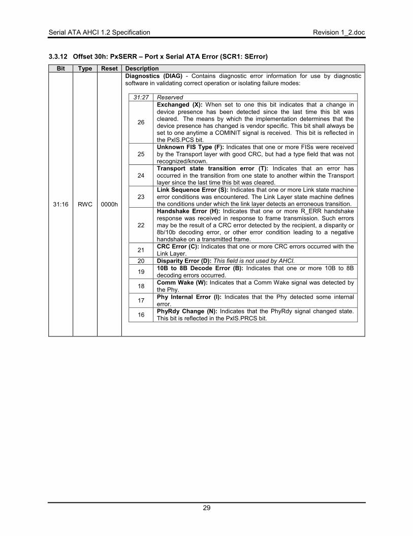
Serial ATA AHCI 1.2 Specification Revision 1_2.doc
29
3.3.12 Offset 30h: PxSERR – Port x Serial ATA Error (SCR1: SError)
Bit Type Reset Description
31:16 RWC 0000h
Diagnostics (DIAG) - Contains diagnostic error information for use by diagnostic software in validating correct operation or isolating failure modes:
31:27 Reserved
26
Exchanged (X): When set to one this bit indicates that a change in device presence has been detected since the last time this bit was cleared. The means by which the implementation determines that the device presence has changed is vendor specific. This bit shall always be set to one anytime a COMINIT signal is received. This bit is reflected in the PxIS.PCS bit.
25 Unknown FIS Type (F): Indicates that one or more FISs were received by the Transport layer with good CRC, but had a type field that was not recognized/known.
24 Transport state transition error (T): Indicates that an error has occurred in the transition from one state to another within the Transport layer since the last time this bit was cleared.
23 Link Sequence Error (S): Indicates that one or more Link state machine error conditions was encountered. The Link Layer state machine defines the conditions under which the link layer detects an erroneous transition.
22
Handshake Error (H): Indicates that one or more R_ERR handshake response was received in response to frame transmission. Such errors may be the result of a CRC error detected by the recipient, a disparity or 8b/10b decoding error, or other error condition leading to a negative handshake on a transmitted frame.
21 CRC Error (C): Indicates that one or more CRC errors occurred with the Link Layer.
20 Disparity Error (D): This field is not used by AHCI.
19 10B to 8B Decode Error (B): Indicates that one or more 10B to 8B decoding errors occurred.
18 Comm Wake (W): Indicates that a Comm Wake signal was detected by the Phy.
17 Phy Internal Error (I): Indicates that the Phy detected some internal error.
16 PhyRdy Change (N): Indicates that the PhyRdy signal changed state. This bit is reflected in the PxIS.PRCS bit.
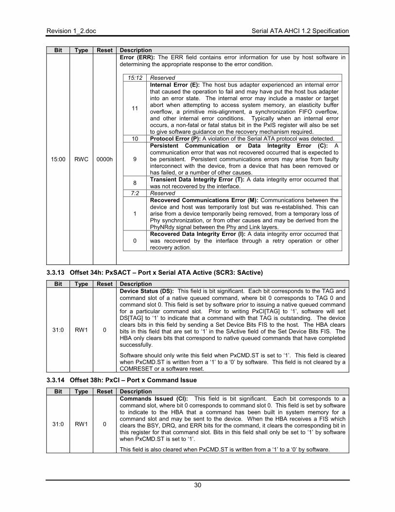
Revision 1_2.doc Serial ATA AHCI 1.2 Specification
30
Bit Type Reset Description
15:00 RWC 0000h
Error (ERR): The ERR field contains error information for use by host software in determining the appropriate response to the error condition.
15:12 Reserved
11
Internal Error (E): The host bus adapter experienced an internal error that caused the operation to fail and may have put the host bus adapter into an error state. The internal error may include a master or target abort when attempting to access system memory, an elasticity buffer overflow, a primitive mis-alignment, a synchronization FIFO overflow, and other internal error conditions. Typically when an internal error occurs, a non-fatal or fatal status bit in the PxIS register will also be set to give software guidance on the recovery mechanism required.
10 Protocol Error (P): A violation of the Serial ATA protocol was detected.
9
Persistent Communication or Data Integrity Error (C): Acommunication error that was not recovered occurred that is expected to be persistent. Persistent communications errors may arise from faulty interconnect with the device, from a device that has been removed or has failed, or a number of other causes.
8 Transient Data Integrity Error (T): A data integrity error occurred that was not recovered by the interface.
7:2 Reserved
1
Recovered Communications Error (M): Communications between the device and host was temporarily lost but was re-established. This can arise from a device temporarily being removed, from a temporary loss of Phy synchronization, or from other causes and may be derived from the PhyNRdy signal between the Phy and Link layers.
0Recovered Data Integrity Error (I): A data integrity error occurred that was recovered by the interface through a retry operation or other recovery action.
3.3.13 Offset 34h: PxSACT – Port x Serial ATA Active (SCR3: SActive)
Bit Type Reset Description
31:0 RW1 0
Device Status (DS): This field is bit significant. Each bit corresponds to the TAG and command slot of a native queued command, where bit 0 corresponds to TAG 0 and command slot 0. This field is set by software prior to issuing a native queued command for a particular command slot. Prior to writing PxCI[TAG] to ‘1’, software will set DS[TAG] to ‘1’ to indicate that a command with that TAG is outstanding. The device clears bits in this field by sending a Set Device Bits FIS to the host. The HBA clears bits in this field that are set to ‘1’ in the SActive field of the Set Device Bits FIS. The HBA only clears bits that correspond to native queued commands that have completed successfully.
Software should only write this field when PxCMD.ST is set to ‘1’. This field is cleared when PxCMD.ST is written from a ‘1’ to a ‘0’ by software. This field is not cleared by a COMRESET or a software reset.
3.3.14 Offset 38h: PxCI – Port x Command Issue
Bit Type Reset Description
31:0 RW1 0
Commands Issued (CI): This field is bit significant. Each bit corresponds to a command slot, where bit 0 corresponds to command slot 0. This field is set by software to indicate to the HBA that a command has been built in system memory for a command slot and may be sent to the device. When the HBA receives a FIS which clears the BSY, DRQ, and ERR bits for the command, it clears the corresponding bit in this register for that command slot. Bits in this field shall only be set to ‘1’ by software when PxCMD.ST is set to ‘1’.
This field is also cleared when PxCMD.ST is written from a ‘1’ to a ‘0’ by software.
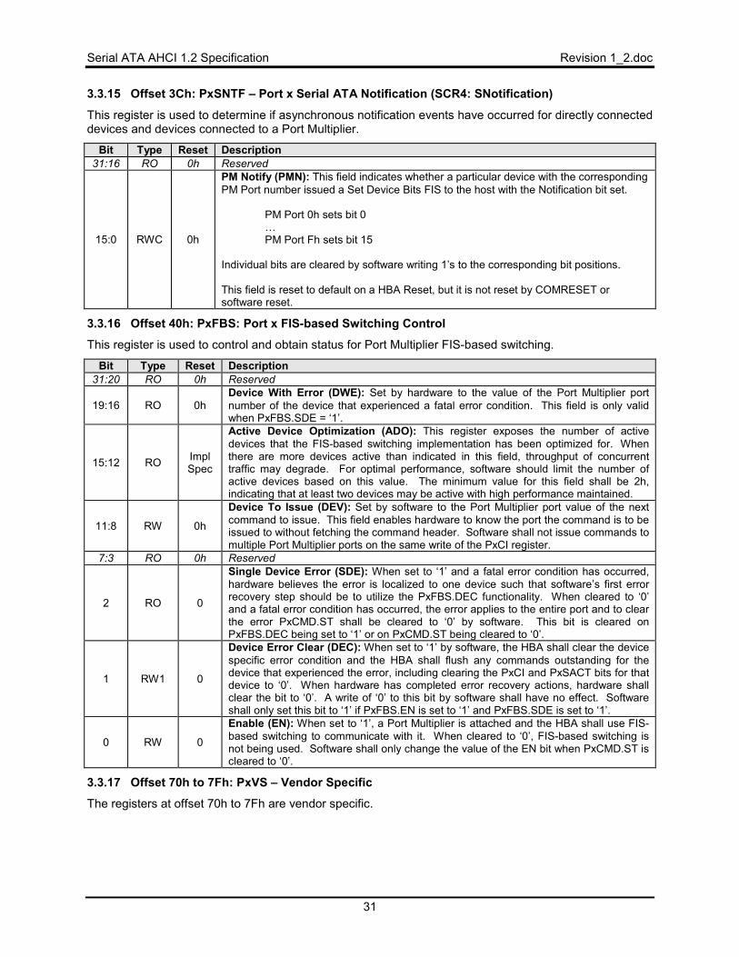
Serial ATA AHCI 1.2 Specification Revision 1_2.doc
31
3.3.15 Offset 3Ch: PxSNTF – Port x Serial ATA Notification (SCR4: SNotification)
This register is used to determine if asynchronous notification events have occurred for directly connected devices and devices connected to a Port Multiplier.
Bit Type Reset Description 31:16 RO 0h Reserved
15:0 RWC 0h
PM Notify (PMN): This field indicates whether a particular device with the corresponding PM Port number issued a Set Device Bits FIS to the host with the Notification bit set.
PM Port 0h sets bit 0 …PM Port Fh sets bit 15
Individual bits are cleared by software writing 1’s to the corresponding bit positions. This field is reset to default on a HBA Reset, but it is not reset by COMRESET or software reset.
3.3.16 Offset 40h: PxFBS: Port x FIS-based Switching Control
This register is used to control and obtain status for Port Multiplier FIS-based switching.
Bit Type Reset Description 31:20 RO 0h Reserved
19:16 RO 0h Device With Error (DWE): Set by hardware to the value of the Port Multiplier port number of the device that experienced a fatal error condition. This field is only valid when PxFBS.SDE = ‘1’.
15:12 RO Impl Spec
Active Device Optimization (ADO): This register exposes the number of active devices that the FIS-based switching implementation has been optimized for. When there are more devices active than indicated in this field, throughput of concurrent traffic may degrade. For optimal performance, software should limit the number of active devices based on this value. The minimum value for this field shall be 2h, indicating that at least two devices may be active with high performance maintained.
11:8 RW 0h
Device To Issue (DEV): Set by software to the Port Multiplier port value of the next command to issue. This field enables hardware to know the port the command is to be issued to without fetching the command header. Software shall not issue commands to multiple Port Multiplier ports on the same write of the PxCI register.
7:3 RO 0h Reserved
2 RO 0
Single Device Error (SDE): When set to ‘1’ and a fatal error condition has occurred, hardware believes the error is localized to one device such that software’s first error recovery step should be to utilize the PxFBS.DEC functionality. When cleared to ‘0’ and a fatal error condition has occurred, the error applies to the entire port and to clear the error PxCMD.ST shall be cleared to ‘0’ by software. This bit is cleared on PxFBS.DEC being set to ‘1’ or on PxCMD.ST being cleared to ‘0’.
1 RW1 0
Device Error Clear (DEC): When set to ‘1’ by software, the HBA shall clear the device specific error condition and the HBA shall flush any commands outstanding for the device that experienced the error, including clearing the PxCI and PxSACT bits for that device to ‘0’. When hardware has completed error recovery actions, hardware shall clear the bit to ‘0’. A write of ‘0’ to this bit by software shall have no effect. Software shall only set this bit to ‘1’ if PxFBS.EN is set to ‘1’ and PxFBS.SDE is set to ‘1’.
0 RW 0
Enable (EN): When set to ‘1’, a Port Multiplier is attached and the HBA shall use FIS-based switching to communicate with it. When cleared to ‘0’, FIS-based switching is not being used. Software shall only change the value of the EN bit when PxCMD.ST is cleared to ‘0’.
3.3.17 Offset 70h to 7Fh: PxVS – Vendor Specific
The registers at offset 70h to 7Fh are vendor specific.
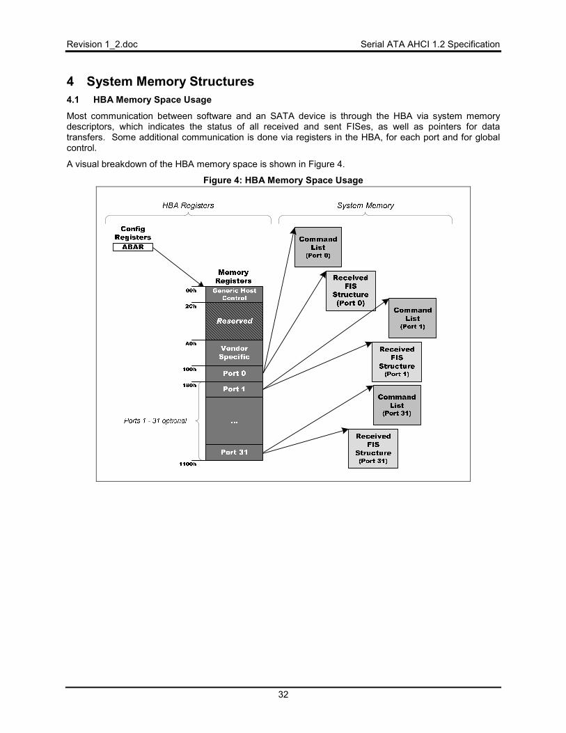
Revision 1_2.doc Serial ATA AHCI 1.2 Specification
32
4 System Memory Structures 4.1 HBA Memory Space Usage
Most communication between software and an SATA device is through the HBA via system memory descriptors, which indicates the status of all received and sent FISes, as well as pointers for data transfers. Some additional communication is done via registers in the HBA, for each port and for global control.
A visual breakdown of the HBA memory space is shown in Figure 4.
Figure 4: HBA Memory Space Usage
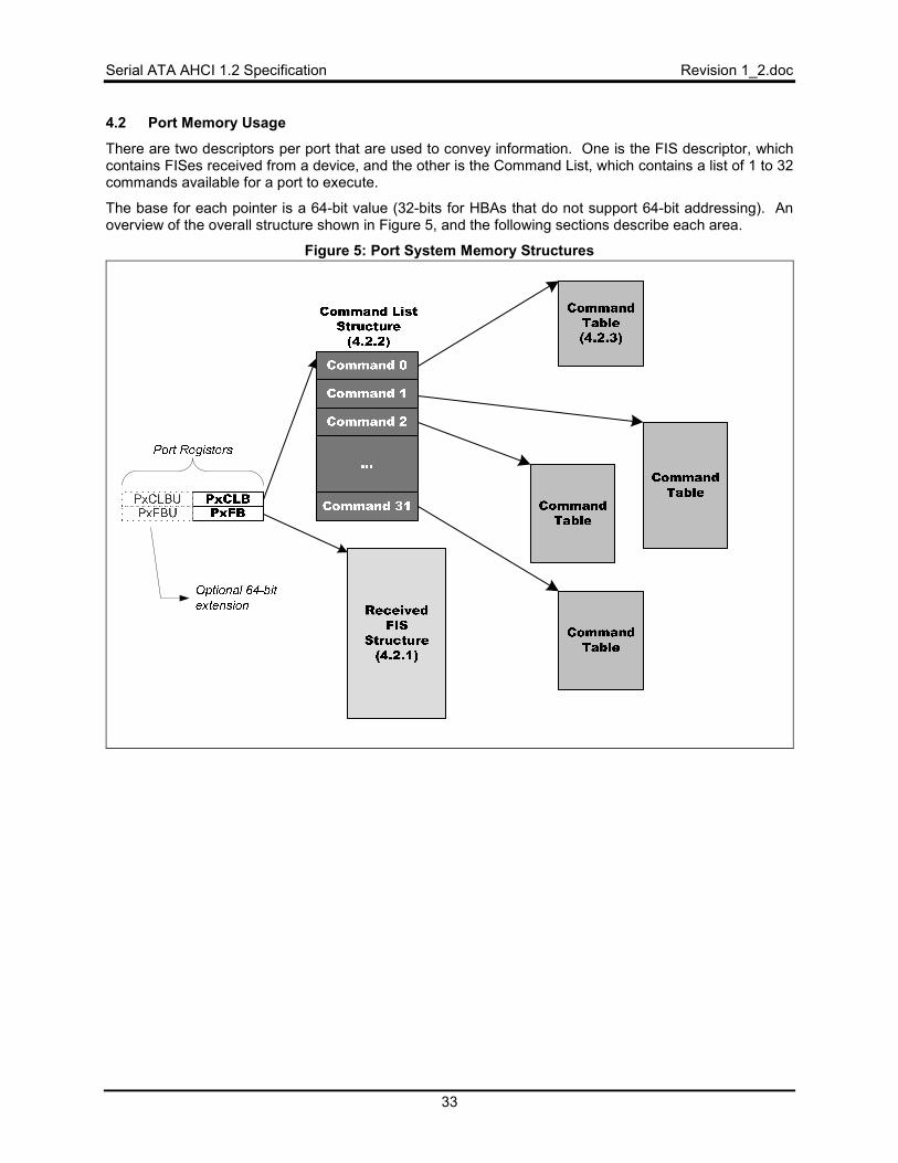
Serial ATA AHCI 1.2 Specification Revision 1_2.doc
33
4.2 Port Memory Usage
There are two descriptors per port that are used to convey information. One is the FIS descriptor, which contains FISes received from a device, and the other is the Command List, which contains a list of 1 to 32 commands available for a port to execute.
The base for each pointer is a 64-bit value (32-bits for HBAs that do not support 64-bit addressing). An overview of the overall structure shown in Figure 5, and the following sections describe each area.
Figure 5: Port System Memory Structures
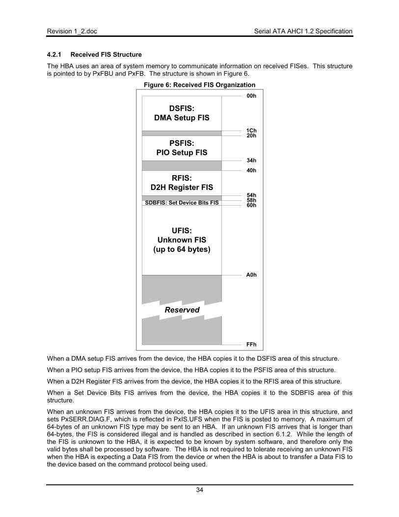
Revision 1_2.doc Serial ATA AHCI 1.2 Specification
34
4.2.1 Received FIS Structure
The HBA uses an area of system memory to communicate information on received FISes. This structure is pointed to by PxFBU and PxFB. The structure is shown in Figure 6.
Figure 6: Received FIS Organization
Reserved
DSFIS:DMA Setup FIS
00h
20h
FFh
34h
1Ch
PSFIS:PIO Setup FIS
40hRFIS:
D2H Register FIS
60h
54h
UFIS:Unknown FIS
(up to 64 bytes)
A0h
SDBFIS: Set Device Bits FIS 58h
When a DMA setup FIS arrives from the device, the HBA copies it to the DSFIS area of this structure.
When a PIO setup FIS arrives from the device, the HBA copies it to the PSFIS area of this structure.
When a D2H Register FIS arrives from the device, the HBA copies it to the RFIS area of this structure.
When a Set Device Bits FIS arrives from the device, the HBA copies it to the SDBFIS area of this structure.
When an unknown FIS arrives from the device, the HBA copies it to the UFIS area in this structure, and sets PxSERR.DIAG.F, which is reflected in PxIS.UFS when the FIS is posted to memory. A maximum of 64-bytes of an unknown FIS type may be sent to an HBA. If an unknown FIS arrives that is longer than 64-bytes, the FIS is considered illegal and is handled as described in section 6.1.2. While the length of the FIS is unknown to the HBA, it is expected to be known by system software, and therefore only the valid bytes shall be processed by software. The HBA is not required to tolerate receiving an unknown FIS when the HBA is expecting a Data FIS from the device or when the HBA is about to transfer a Data FIS to the device based on the command protocol being used.
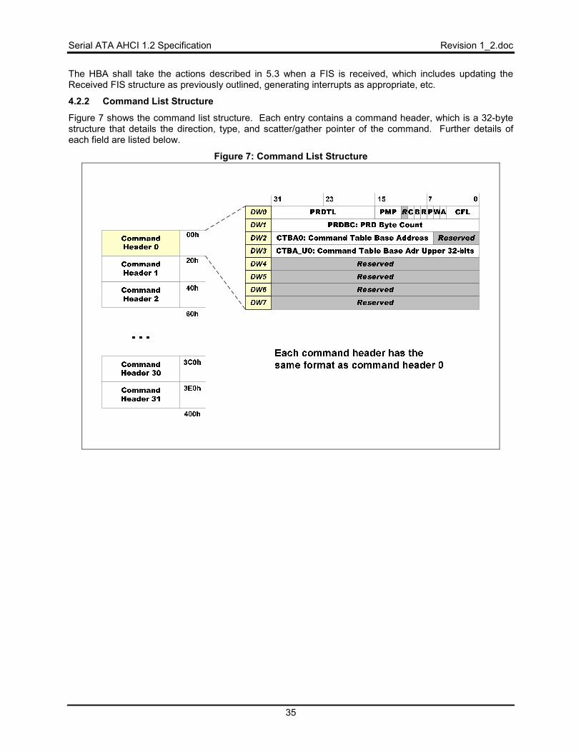
Serial ATA AHCI 1.2 Specification Revision 1_2.doc
35
The HBA shall take the actions described in 5.3 when a FIS is received, which includes updating the Received FIS structure as previously outlined, generating interrupts as appropriate, etc.
4.2.2 Command List Structure
Figure 7 shows the command list structure. Each entry contains a command header, which is a 32-byte structure that details the direction, type, and scatter/gather pointer of the command. Further details of each field are listed below.
Figure 7: Command List Structure
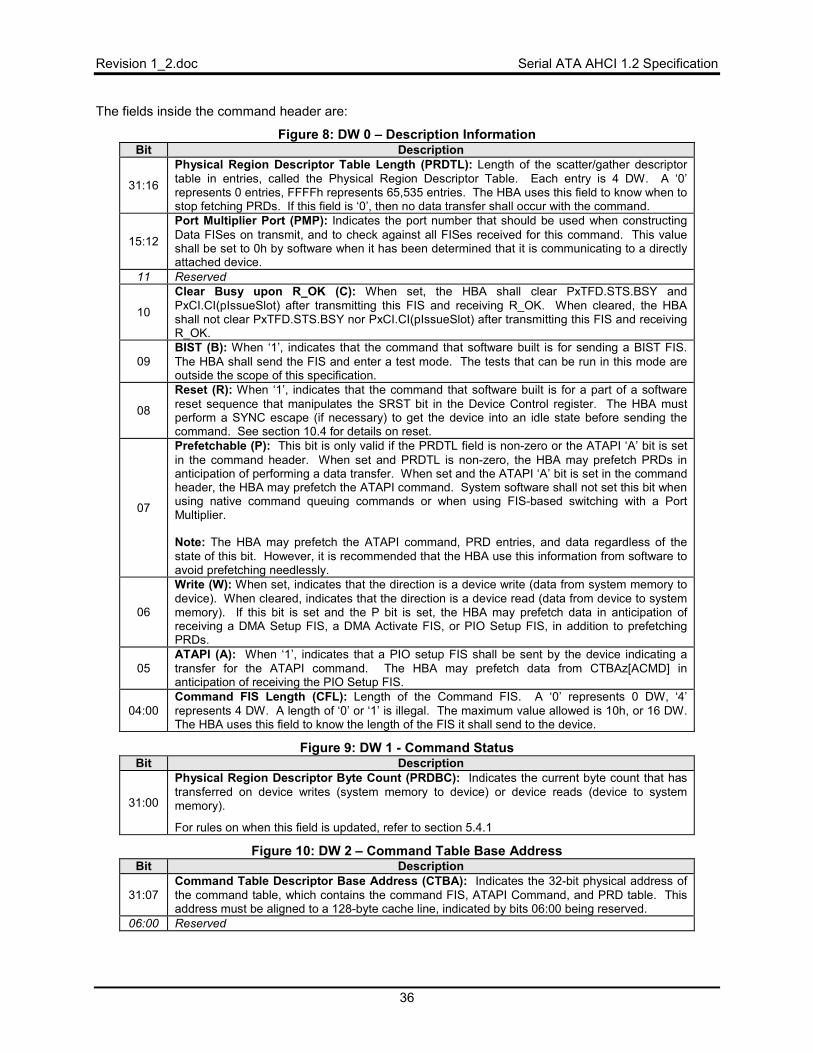
Revision 1_2.doc Serial ATA AHCI 1.2 Specification
36
The fields inside the command header are:
Figure 8: DW 0 – Description Information Bit Description
31:16
Physical Region Descriptor Table Length (PRDTL): Length of the scatter/gather descriptor table in entries, called the Physical Region Descriptor Table. Each entry is 4 DW. A ‘0’ represents 0 entries, FFFFh represents 65,535 entries. The HBA uses this field to know when to stop fetching PRDs. If this field is ‘0’, then no data transfer shall occur with the command.
15:12
Port Multiplier Port (PMP): Indicates the port number that should be used when constructing Data FISes on transmit, and to check against all FISes received for this command. This value shall be set to 0h by software when it has been determined that it is communicating to a directly attached device.
11 Reserved
10
Clear Busy upon R_OK (C): When set, the HBA shall clear PxTFD.STS.BSY and PxCI.CI(pIssueSlot) after transmitting this FIS and receiving R_OK. When cleared, the HBA shall not clear PxTFD.STS.BSY nor PxCI.CI(pIssueSlot) after transmitting this FIS and receiving R_OK.
09 BIST (B): When ‘1’, indicates that the command that software built is for sending a BIST FIS. The HBA shall send the FIS and enter a test mode. The tests that can be run in this mode are outside the scope of this specification.
08
Reset (R): When ‘1’, indicates that the command that software built is for a part of a software reset sequence that manipulates the SRST bit in the Device Control register. The HBA must perform a SYNC escape (if necessary) to get the device into an idle state before sending the command. See section 10.4 for details on reset.
07
Prefetchable (P): This bit is only valid if the PRDTL field is non-zero or the ATAPI ‘A’ bit is set in the command header. When set and PRDTL is non-zero, the HBA may prefetch PRDs in anticipation of performing a data transfer. When set and the ATAPI ‘A’ bit is set in the command header, the HBA may prefetch the ATAPI command. System software shall not set this bit when using native command queuing commands or when using FIS-based switching with a Port Multiplier. Note: The HBA may prefetch the ATAPI command, PRD entries, and data regardless of the state of this bit. However, it is recommended that the HBA use this information from software to avoid prefetching needlessly.
06
Write (W): When set, indicates that the direction is a device write (data from system memory to device). When cleared, indicates that the direction is a device read (data from device to system memory). If this bit is set and the P bit is set, the HBA may prefetch data in anticipation of receiving a DMA Setup FIS, a DMA Activate FIS, or PIO Setup FIS, in addition to prefetching PRDs.
05 ATAPI (A): When ‘1’, indicates that a PIO setup FIS shall be sent by the device indicating a transfer for the ATAPI command. The HBA may prefetch data from CTBAz[ACMD] in anticipation of receiving the PIO Setup FIS.
04:00 Command FIS Length (CFL): Length of the Command FIS. A ‘0’ represents 0 DW, ‘4’ represents 4 DW. A length of ‘0’ or ‘1’ is illegal. The maximum value allowed is 10h, or 16 DW. The HBA uses this field to know the length of the FIS it shall send to the device.
Figure 9: DW 1 - Command Status Bit Description
31:00
Physical Region Descriptor Byte Count (PRDBC): Indicates the current byte count that has transferred on device writes (system memory to device) or device reads (device to system memory).
For rules on when this field is updated, refer to section 5.4.1
Figure 10: DW 2 – Command Table Base Address Bit Description
31:07 Command Table Descriptor Base Address (CTBA): Indicates the 32-bit physical address of the command table, which contains the command FIS, ATAPI Command, and PRD table. This address must be aligned to a 128-byte cache line, indicated by bits 06:00 being reserved.
06:00 Reserved
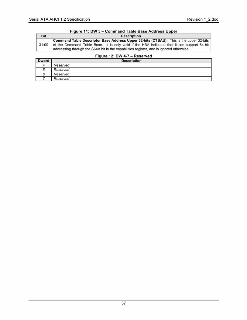
Serial ATA AHCI 1.2 Specification Revision 1_2.doc
37
Figure 11: DW 3 – Command Table Base Address Upper Bit Description
31:00 Command Table Descriptor Base Address Upper 32-bits (CTBAU): This is the upper 32-bits of the Command Table Base. It is only valid if the HBA indicated that it can support 64-bit addressing through the S64A bit in the capabilities register, and is ignored otherwise.
Figure 12: DW 4-7 – Reserved Dword Description
4 Reserved 5 Reserved 6 Reserved 7 Reserved
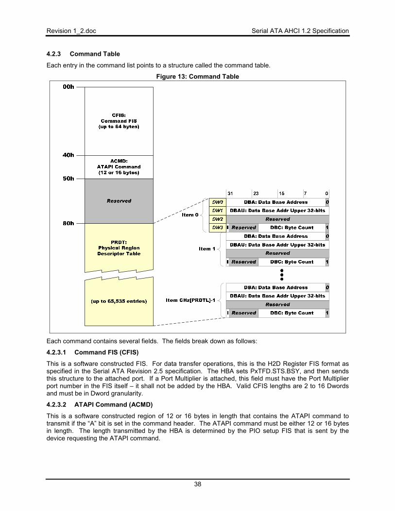
Revision 1_2.doc Serial ATA AHCI 1.2 Specification
38
4.2.3 Command Table
Each entry in the command list points to a structure called the command table.
Figure 13: Command Table
Each command contains several fields. The fields break down as follows:
4.2.3.1 Command FIS (CFIS)
This is a software constructed FIS. For data transfer operations, this is the H2D Register FIS format as specified in the Serial ATA Revision 2.5 specification. The HBA sets PxTFD.STS.BSY, and then sends this structure to the attached port. If a Port Multiplier is attached, this field must have the Port Multiplier port number in the FIS itself – it shall not be added by the HBA. Valid CFIS lengths are 2 to 16 Dwords and must be in Dword granularity.
4.2.3.2 ATAPI Command (ACMD)
This is a software constructed region of 12 or 16 bytes in length that contains the ATAPI command to transmit if the “A” bit is set in the command header. The ATAPI command must be either 12 or 16 bytes in length. The length transmitted by the HBA is determined by the PIO setup FIS that is sent by the device requesting the ATAPI command.
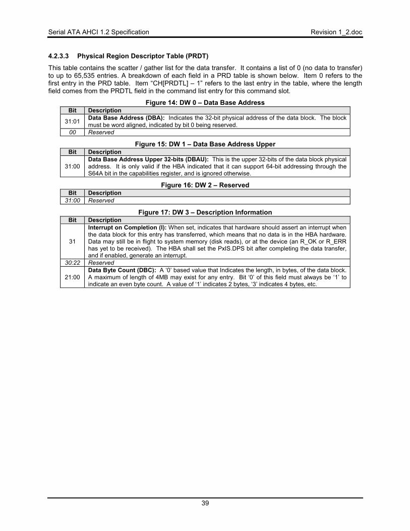
Serial ATA AHCI 1.2 Specification Revision 1_2.doc
39
4.2.3.3 Physical Region Descriptor Table (PRDT)
This table contains the scatter / gather list for the data transfer. It contains a list of 0 (no data to transfer) to up to 65,535 entries. A breakdown of each field in a PRD table is shown below. Item 0 refers to the first entry in the PRD table. Item “CH[PRDTL] – 1” refers to the last entry in the table, where the length field comes from the PRDTL field in the command list entry for this command slot.
Figure 14: DW 0 – Data Base Address Bit Description
31:01 Data Base Address (DBA): Indicates the 32-bit physical address of the data block. The block must be word aligned, indicated by bit 0 being reserved.
00 Reserved
Figure 15: DW 1 – Data Base Address Upper Bit Description
31:00 Data Base Address Upper 32-bits (DBAU): This is the upper 32-bits of the data block physical address. It is only valid if the HBA indicated that it can support 64-bit addressing through the S64A bit in the capabilities register, and is ignored otherwise.
Figure 16: DW 2 – Reserved Bit Description
31:00 Reserved
Figure 17: DW 3 – Description Information Bit Description
31
Interrupt on Completion (I): When set, indicates that hardware should assert an interrupt when the data block for this entry has transferred, which means that no data is in the HBA hardware. Data may still be in flight to system memory (disk reads), or at the device (an R_OK or R_ERR has yet to be received). The HBA shall set the PxIS.DPS bit after completing the data transfer, and if enabled, generate an interrupt.
30:22 Reserved
21:00 Data Byte Count (DBC): A ‘0’ based value that Indicates the length, in bytes, of the data block. A maximum of length of 4MB may exist for any entry. Bit ‘0’ of this field must always be ‘1’ to indicate an even byte count. A value of ‘1’ indicates 2 bytes, ‘3’ indicates 4 bytes, etc.
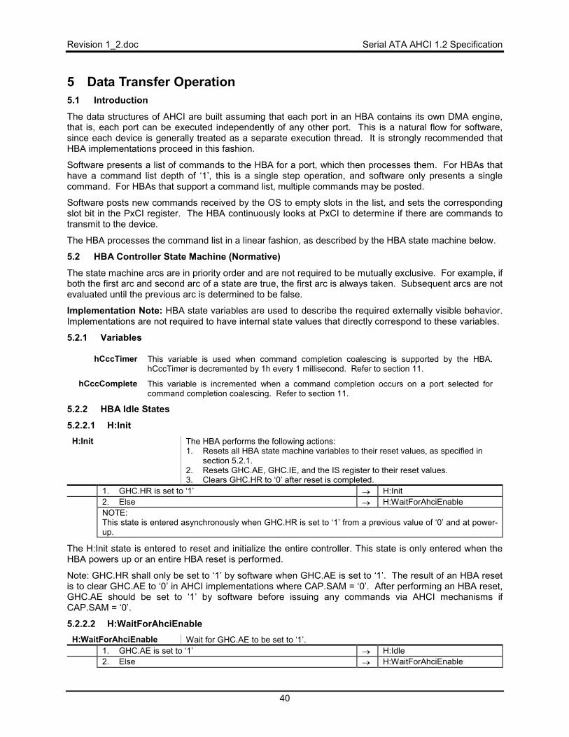
Revision 1_2.doc Serial ATA AHCI 1.2 Specification
40
5 Data Transfer Operation 5.1 Introduction
The data structures of AHCI are built assuming that each port in an HBA contains its own DMA engine, that is, each port can be executed independently of any other port. This is a natural flow for software, since each device is generally treated as a separate execution thread. It is strongly recommended that HBA implementations proceed in this fashion.
Software presents a list of commands to the HBA for a port, which then processes them. For HBAs that have a command list depth of ‘1’, this is a single step operation, and software only presents a single command. For HBAs that support a command list, multiple commands may be posted.
Software posts new commands received by the OS to empty slots in the list, and sets the corresponding slot bit in the PxCI register. The HBA continuously looks at PxCI to determine if there are commands to transmit to the device.
The HBA processes the command list in a linear fashion, as described by the HBA state machine below.
5.2 HBA Controller State Machine (Normative)
The state machine arcs are in priority order and are not required to be mutually exclusive. For example, if both the first arc and second arc of a state are true, the first arc is always taken. Subsequent arcs are not evaluated until the previous arc is determined to be false.
Implementation Note: HBA state variables are used to describe the required externally visible behavior. Implementations are not required to have internal state values that directly correspond to these variables.
5.2.1 Variables
hCccTimer This variable is used when command completion coalescing is supported by the HBA. hCccTimer is decremented by 1h every 1 millisecond. Refer to section 11.
hCccComplete This variable is incremented when a command completion occurs on a port selected for command completion coalescing. Refer to section 11.
5.2.2 HBA Idle States
5.2.2.1 H:Init H:Init The HBA performs the following actions:
1. Resets all HBA state machine variables to their reset values, as specified in section 5.2.1.
2. Resets GHC.AE, GHC.IE, and the IS register to their reset values. 3. Clears GHC.HR to ‘0’ after reset is completed.
1. GHC.HR is set to ‘1’ → H:Init 2. Else → H:WaitForAhciEnable NOTE: This state is entered asynchronously when GHC.HR is set to ‘1’ from a previous value of ‘0’ and at power-up.
The H:Init state is entered to reset and initialize the entire controller. This state is only entered when the HBA powers up or an entire HBA reset is performed.
Note: GHC.HR shall only be set to ‘1’ by software when GHC.AE is set to ‘1’. The result of an HBA reset is to clear GHC.AE to ‘0’ in AHCI implementations where CAP.SAM = ‘0’. After performing an HBA reset, GHC.AE should be set to ‘1’ by software before issuing any commands via AHCI mechanisms if CAP.SAM = ‘0’.
5.2.2.2 H:WaitForAhciEnable H:WaitForAhciEnable Wait for GHC.AE to be set to ‘1’.
1. GHC.AE is set to ‘1’ → H:Idle 2. Else → H:WaitForAhciEnable
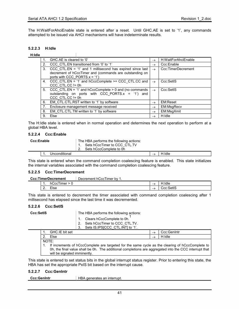
Serial ATA AHCI 1.2 Specification Revision 1_2.doc
41
The H:WaitForAhciEnable state is entered after a reset. Until GHC.AE is set to ‘1’, any commands attempted to be issued via AHCI mechanisms will have indeterminate results.
5.2.2.3 H:Idle H:Idle
1. GHC.AE is cleared to ‘0’ → H:WaitForAhciEnable 2. CCC_CTL.EN transitioned from ‘0’ to ‘1’ → Ccc:Enable 3. CCC_CTL.EN = ‘1’ and 1 millisecond has expired since last
decrement of hCccTimer and (commands are outstanding on ports with CCC_PORTS.x = ‘1’)
→ Ccc:TimerDecrement
4. CCC_CTL.EN = ‘1’ and hCccComplete >= CCC_CTL.CC and CCC_CTL.CC != 0h
→ Ccc:SetIS
5. CCC_CTL.EN = ‘1’ and hCccComplete > 0 and (no commands outstanding on ports with CCC_PORTS.x = ‘1’) and CCC_CTL.CC != 0h
→ Ccc:SetIS
6. EM_CTL.CTL.RST written to ‘1’ by software → EM:Reset 7. Enclosure management message received → EM:MsgRecv 8. EM_CTL.CTL.TM written to ‘1’ by software → EM:MsgXmit 9. Else → H:Idle
The H:Idle state is entered when in normal operation and determines the next operation to perform at a global HBA level.
5.2.2.4 Ccc:Enable Ccc:Enable The HBA performs the following actions:
1. Sets hCccTimer to CCC_CTL.TV 2. Sets hCccComplete to 0h
1. Unconditional → H:Idle
This state is entered when the command completion coalescing feature is enabled. This state initializes the internal variables associated with the command completion coalescing feature.
5.2.2.5 Ccc:TimerDecrement Ccc:TimerDecrement Decrement hCccTimer by 1.
1. hCccTimer > 0 → H:Idle 2. Else → Ccc:SetIS
This state is entered to decrement the timer associated with command completion coalescing after 1 millisecond has elapsed since the last time it was decremented.
5.2.2.6 Ccc:SetIS Ccc:SetIS The HBA performs the following actions:
1. Clears hCccComplete to 0h.1
2. Sets hCccTimer to CCC_CTL.TV. 3. Sets IS.IPS[CCC_CTL.INT] to ‘1’.
1. GHC.IE bit set → Ccc:GenIntr 2. Else → H:Idle NOTE: 1. If increments of hCccComplete are targeted for the same cycle as the clearing of hCccComplete to
0h, the final value shall be 0h. The additional completions are aggregated into the CCC interrupt that will be signaled imminently.
This state is entered to set status bits in the global interrupt status register. Prior to entering this state, the HBA has set the appropriate PxIS bit based on the interrupt cause.
5.2.2.7 Ccc:GenIntr Ccc:GenIntr HBA generates an interrupt.
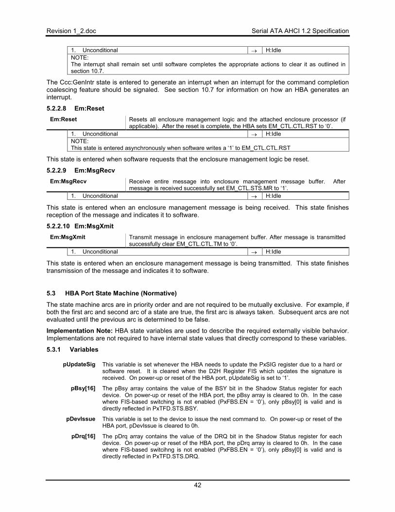
Revision 1_2.doc Serial ATA AHCI 1.2 Specification
42
1. Unconditional → H:Idle NOTE: The interrupt shall remain set until software completes the appropriate actions to clear it as outlined in section 10.7.
The Ccc:GenIntr state is entered to generate an interrupt when an interrupt for the command completion coalescing feature should be signaled. See section 10.7 for information on how an HBA generates an interrupt.
5.2.2.8 Em:Reset Em:Reset Resets all enclosure management logic and the attached enclosure processor (if
applicable). After the reset is complete, the HBA sets EM_CTL.CTL.RST to ‘0’. 1. Unconditional → H:Idle NOTE: This state is entered asynchronously when software writes a ‘1’ to EM_CTL.CTL.RST
This state is entered when software requests that the enclosure management logic be reset.
5.2.2.9 Em:MsgRecv Em:MsgRecv Receive entire message into enclosure management message buffer. After
message is received successfully set EM_CTL.STS.MR to ‘1’. 1. Unconditional → H:Idle
This state is entered when an enclosure management message is being received. This state finishes reception of the message and indicates it to software.
5.2.2.10 Em:MsgXmit Em:MsgXmit Transmit message in enclosure management buffer. After message is transmitted
successfully clear EM_CTL.CTL.TM to ‘0’. 1. Unconditional → H:Idle
This state is entered when an enclosure management message is being transmitted. This state finishes transmission of the message and indicates it to software.
5.3 HBA Port State Machine (Normative)
The state machine arcs are in priority order and are not required to be mutually exclusive. For example, if both the first arc and second arc of a state are true, the first arc is always taken. Subsequent arcs are not evaluated until the previous arc is determined to be false.
Implementation Note: HBA state variables are used to describe the required externally visible behavior. Implementations are not required to have internal state values that directly correspond to these variables.
5.3.1 Variables
pUpdateSig This variable is set whenever the HBA needs to update the PxSIG register due to a hard or software reset. It is cleared when the D2H Register FIS which updates the signature is received. On power-up or reset of the HBA port, pUpdateSig is set to ‘1’.
pBsy[16] The pBsy array contains the value of the BSY bit in the Shadow Status register for each device. On power-up or reset of the HBA port, the pBsy array is cleared to 0h. In the case where FIS-based switching is not enabled (PxFBS.EN = ‘0’), only pBsy[0] is valid and is directly reflected in PxTFD.STS.BSY.
pDevIssue This variable is set to the device to issue the next command to. On power-up or reset of the HBA port, pDevIssue is cleared to 0h.
pDrq[16] The pDrq array contains the value of the DRQ bit in the Shadow Status register for each device. On power-up or reset of the HBA port, the pDrq array is cleared to 0h. In the case where FIS-based switcihng is not enabled (PxFBS.EN = ‘0’), only pBsy[0] is valid and is directly reflected in PxTFD.STS.DRQ.
Serial ATA AHCI 1.2 Specification Revision 1_2.doc
43
pPmpCur The value of the Port Multiplier Port (PMP) field in the last FIS received. On power-up or reset of the HBA port, pPmpCur is set to 0h.
pIssueSlot[16] The pIssueSlot variable contains the command slot location of the last command issued to each of the devices. On power-up or reset of the HBA port, all pIssueSlot variables are set to 32. When FIS-based switching is not enabled, only the first value in the array is used.
pDataSlot[16] Each pDataSlot element contains the command slot location of the command to transfer data for the corresponding device. On power-up or reset of the HBA port, all pDataSlot variables are cleared to 0h. When FIS-based switching is not enabled, only the first value in the array is used.
pPMP The pPMP variable contains the value in the PMP field of the command table of the last command FIS transferred to the device. On power-up or reset of the HBA port, pPMP is cleared to 0h.
pXferAtapi The pXferAtapi variable is set to ‘1’ when a command is issued that had the A bit set for a particular transfer. The pXferAtapi variable is cleared to ‘0’ when a Data FIS is transferred to the device that contains the ATAPI command from the command list. On power-up or reset of the HBA port, pXferAtapi is cleared to ‘0’.
pPioXfer[16] The pPioXfer[x] variable is set to ‘1’ when a PIO Setup FIS is received with a PMP value of x. This variable is used after a data transfer occurs in order to update the Status register appropriately. When FIS-based switching is not enabled, only the first value in the array is used.
pPioESts The pPioESts variable is set to the E_Status field of the PIO Setup FIS to be stored until the data for the DRQ block is transferred. On power-up or reset of the HBA port, pPioESts is cleared to ‘0’.
pPioErr The pPioErr variable is set to the Error field of the PIO Setup FIS to be stored until the data for the DRQ block is transferred. On power-up or reset of the HBA port, pPioErr is cleared to ‘0’.
pPioIbit The pPioIbit variable is set to the I bit of the PIO Setup FIS to be stored until the data for the DRQ block is transferred. On power-up or reset of the HBA port, pPioIbit is cleared to ‘0’.
pDmaXferCnt The pDmaXferCnt variable is set to the DMA transfer count for a particular DMA transfer. The DMA transfer may consist of multiple Data FISes. The pDmaXferCnt variable is decremented by the size of a Data FIS on each successful reception of a Data FIS. On power-up or reset of the HBA port, pDmaXferCnt is cleared to 0h. An pDmaXferCnt = 0hsignals that there was no DMA Setup FIS or PIO Setup FIS corresponding to the data transfer and that the transfer lengths should be constructed based on the PRD table entries only.
pCmdToIssue This variable is set whenever the currently fetched command still needs to be transmitted to the device. It is used by the state machine to ensure the command is actually transmitted to the device, especially after a command transmission failure. On power-up or reset of the HBA port, pCmdToIssue is cleared to 0h.
pPrdIntr[16] This pPrdIntr[x] variable is set whenever the HBA completes a PRD in either the data transmission or data reception states for the device with a PMP value of x. It is used to generate a PRD interrupt at the end of a successful data FIS. On power-up or reset of the HBA port, pPrdIntr is cleared to 0h. When FIS-based switching is not enabled, only the first value in the array is used.
pSActive This variable is set to the value of the SActive field in a received Set Device Bits FIS. On power-up or reset of the HBA port, pSActive is cleared to 0h.
pSlotLoc This variable is used to track the command slot location the HBA will issue a command from next if one is available in that slot for issue. On power-up or reset of the HBA port, pSlotLoc is cleared to 0h.
Revision 1_2.doc Serial ATA AHCI 1.2 Specification
44
5.3.2 Port Idle States
5.3.2.1 P:Reset P:Reset Wait for controller initialization to complete. Apply reset conditions to all port state
machine variables.
1. HBA reset complete (HBA not in state H:Init) → P:Init 2. Else → P:Reset NOTE: This state is entered asynchronously when GHC.HR is set to ‘1’ from a previous value of ‘0’ and at power-up.
The P:Reset state is entered when the entire controller is undergoing a reset. This state waits for the global controller state to be initialized before continuing.
5.3.2.2 P:Init P:Init The HBA performs the following actions:
1. Resets all port state machine variables to their reset values, as specified in section 5.3.1.
2. Resets all port specific register fields (for all ports) except those fields marked as HwInit and the PxFB/PxFBU/PxCLB/PxCLBU registers.
3. Clears pBsy[0] to ‘0’ and sets pDrq[0] to ‘1’. 4. Resets PxTFD.STS to 7Fh and sets pUpdateSig to ‘1’. 5. Transmits COMRESET to the device if PxCMD.SUD=’1’.
1. Unconditional → P:NotRunning
The P:Init state is entered after a controller reset is completed. P:Init initializes all of the state machine variables and port specific registers. If cold presence detect is supported as specified in PxCMD.CPD, the power to the port is off by default and remains off until software enables power to the port.
5.3.2.3 P:NotRunning P:NotRunning HBA sets all pIssueSlot array variables to 32. HBA sets pSlotLoc = CAP.NCS. For
devices, where x is 1 to 15, pBsy[x] and pDrq[x] variables are cleared to 0h. 1. GHC.AE is cleared to ‘0’ → P:NotRunning 2. PxCMD.POD written to ‘1’ from a ‘0’ → P:PowerOn 3. PxCMD.POD written to ‘0’ from a ‘1’ → P:PowerOff 4. PxSCTL.DET written to ‘4h’ from any other value → P:Offline 5. PxSCTL.DET written to 1h from any other value and
PxCMD.SUD = ‘1’ → P:StartComm
6. PxCMD.SUD written to ‘1’ from ‘0’ and PxSCTL.DET = ‘0h’ → P:StartComm 7. PxCMD.SUD written to ‘0’ from ‘1’ and PxSCTL.DET = ‘0h’ → P:PhyListening 8. PxCMD.FRE written to ‘1’ from a ‘0’ and previously processed
Register FIS is in receive FIFO and PxSERR.DIAG.X = ‘0’ → P:RegFisPostToMem
9. PxCMD.ST = ‘1’ and PxSSTS.IPM = (2h or 6h) → PM:LowPower 10. PxCMD.ST = ‘1’ and PxFBS.EN = ‘1’, PxTFD.STS.BSY =’0’,
and PxTFD.STS.DRQ = ‘0’ → FB:Idle
11. PxCMD.ST = ‘1’, PxTFD.STS.BSY =’0’, and PxTFD.STS.DRQ = ‘0’
→ P:Idle
12. D2H Register FIS received → NDR:Entry 13. Else → P:NotRunning NOTE: 1. This state is entered asynchronously when GHC.AE is transitions from ‘1’ to ‘0’. Disabling AHCI mode
while commands are outstanding has indeterminate results.
In implementations where CAP.SAM is cleared to ‘0’, software shall set GHC.AE to ‘1’ before accessing AHCI registers other than the GHC register. If software accesses AHCI registers other than GHC when GHC.AE is cleared to ‘0’ the results are indeterminate.
Serial ATA AHCI 1.2 Specification Revision 1_2.doc
45
The P:NotRunning state is entered when the port specific DMA engines are not running. The DMA engines may not be running for numerous reasons, including because the PxCMD.ST is cleared to ‘0’ or the communication link with the device has not been established.
Software is only allowed to program the PxCMD.FRE, PxCMD.POD, PxSCTL.DET, and PxCMD.SUD register bits when PxCMD.ST is set to ‘0’, If software programs these bits in any other state (when PxCMD.ST is set to ‘1’), indeterminate results may occur.
5.3.2.4 P:ComInit P:ComInit HBA sets PxTFD.STS to FFh or 80h. HBA sets pBsy[0] and pDrq[0] to reflect the
PxTFD.STS.BSY and PxTFD.STS.DRQ bits. HBA sets PxSSTS.DET to 1h to indicate a device is detected but communication is not yet established. HBA sets PxSERR.DIAG.X to ‘1’.
1. PxIE.PCE is set to ‘1’ → P:ComInitSetIS 2. Else → P:NotRunning NOTE: 1. This state is entered asynchronously when a COMINIT is received from the device.
The P:ComInit state is entered when a COMINIT is received from the device. In this state, the PxTFD.STS register and PxSSTS.DET fields are updated to indicate that a device is present. The PxSERR.DIAG.X bit is set to ‘1’ to indicate a COMINIT has been received.
5.3.2.5 P:ComInitSetIS P:ComInitSetIS HBA sets IS.IPS(x) to ‘1’.
1. GHC.IE = ‘1’ → P:ComInitGenIntr 2. Else → P:NotRunning
This state is entered when a COMINIT is received and the enable for Port Connect Status change interrupts is set to ‘1’.
5.3.2.6 P:ComInitGenIntr P:ComInitGenIntr HBA generates an interrupt.
1. Unconditional → P:NotRunning NOTE: The interrupt shall remain set until software completes the appropriate actions to clear it as outlined in section 10.7.
The P:ComInitGenIntr state is entered to generate an interrupt for the port after a COMINIT is received from the device. See section 10.7 for information on how an HBA generates an interrupt.
5.3.2.7 P:RegFisUpdate P:RegFisUpdate HBA performs the following actions:
1. HBA updates PxSIG with appropriate fields from D2H Register FIS as outlined in 3.3.9, and clears pUpdateSig to ‘0’.
1. PxCMD.FRE = ‘1’ → P:RegFisPostToMem 2. Else → P:NotRunning
The P:RegFisUpdate state is entered to update the PxSIG registers when a D2H Register FIS is received while the PxCMD.ST bit is cleared to ‘0’.
5.3.2.8 P:RegFisPostToMem P:RegFisPostToMem HBA performs the following actions:
1. HBA posts the Register FIS in the receive FIFO to PxFB[RFIS] 2. Updates PxTFD.ERR register with value in the Error field of the Register FIS. 3. Updates PxTFD.STS register with value in the Status field of the Register FIS. 4. Updates pBsy[0] and pDrq[0] to reflect the PxTFD.STS.BSY and
PxTFD.STS.DRQ bits. 1. Unconditional → P:NotRunning
Revision 1_2.doc Serial ATA AHCI 1.2 Specification
46
The P:RegFisPostToMem state is entered to post the initial Register FIS and update the PxTFD register once PxCMD.FRE is set to ‘1’.
5.3.2.9 P:Offline P:Offline HBA puts Phy into offline mode and the Phy voltage level is brought to common-
mode. 1. Unconditional → P:NotRunning
The P:Offline state is entered to place the Phy for the port into offline mode. Offline mode is defined in the Serial ATA Revision 2.5 specification.
5.3.2.10 P:StartBitCleared P:StartBitCleared HBA clears PxCI to 0h, PxSACT to 0h, PxCMD.CCS to 0h, and PxCMD.CR to ‘0’.
HBA clears pDmaXferCnt to 0h. 1. DMA engines for the port not idle → P:StartBitCleared 2. Unconditional → P:NotRunning NOTE: This state is entered asynchronously when software writes the PxCMD.ST bit to a ‘0’ from a previous value of ‘1’ and the HBA is not in state H:Init.
The P:StartBitCleared state is entered when the PxCMD.ST bit is cleared to ‘0’ from a previous value of ‘1’.
5.3.2.11 P:Idle P:Idle HBA sets PxCMD.CR to ‘1’.
1. PxSSTS.DET != 3h → P:NotRunning 2. PxCI != 0h and pIssueSlot[0] = 32 → P:SelectCmd 3. pCmdToIssue = ‘1’ and CTBA(pIssueSlot[0])[R] is set to ‘1’
and pDmaXferCnt = ‘0’ → CFIS:SyncEscape
4. Data FIS received → DR:Entry 5. Non-Data FIS received → NDR:Entry 6. pCmdToIssue = ‘1’ and pDmaXferCnt = ‘0’ → CFIS:Xmit 7. Link layer has negotiated to low power state based on device
power management request → PM:LowPower
8. PxCMD.ICC written → PM:ICC 9. Else → P:Idle
The P:Idle state is entered when in normal operation to determine the next thing to do.
5.3.2.12 P:SelectCmd P:SelectCmd HBA sets pSlotLoc = (pSlotLoc + 1) mod (CAP.NCS + 1). HBA sets pDevIssue =
0h. 1. PxCI.CI(pSlotLoc) = ‘0’ → P:SelectCmd 2. Else (command is selected) → P:FetchCmd
The P:SelectCmd state is entered to select the next command to issue to the device.
Note: The search for a new command to issue is described as an iterative process, where each clock checks a particular CI value. It is shown this way to explicitly indicate the next command to be sent. An implementation may optimize the search in a single clock, so long as the correct command is selected.
5.3.2.13 P:FetchCmd P:FetchCmd The HBA performs the following actions in the order specified:
1. HBA fetches command header from PxCLB[CH(pSlotLoc)] 2. HBA sets pIssueSlot[0] = pSlotLoc 3. HBA sets PxCMD.CCS = pSlotLoc 4. HBA sets pCmdToIssue = ‘1’ 5. HBA may prefetch the command FIS from memory
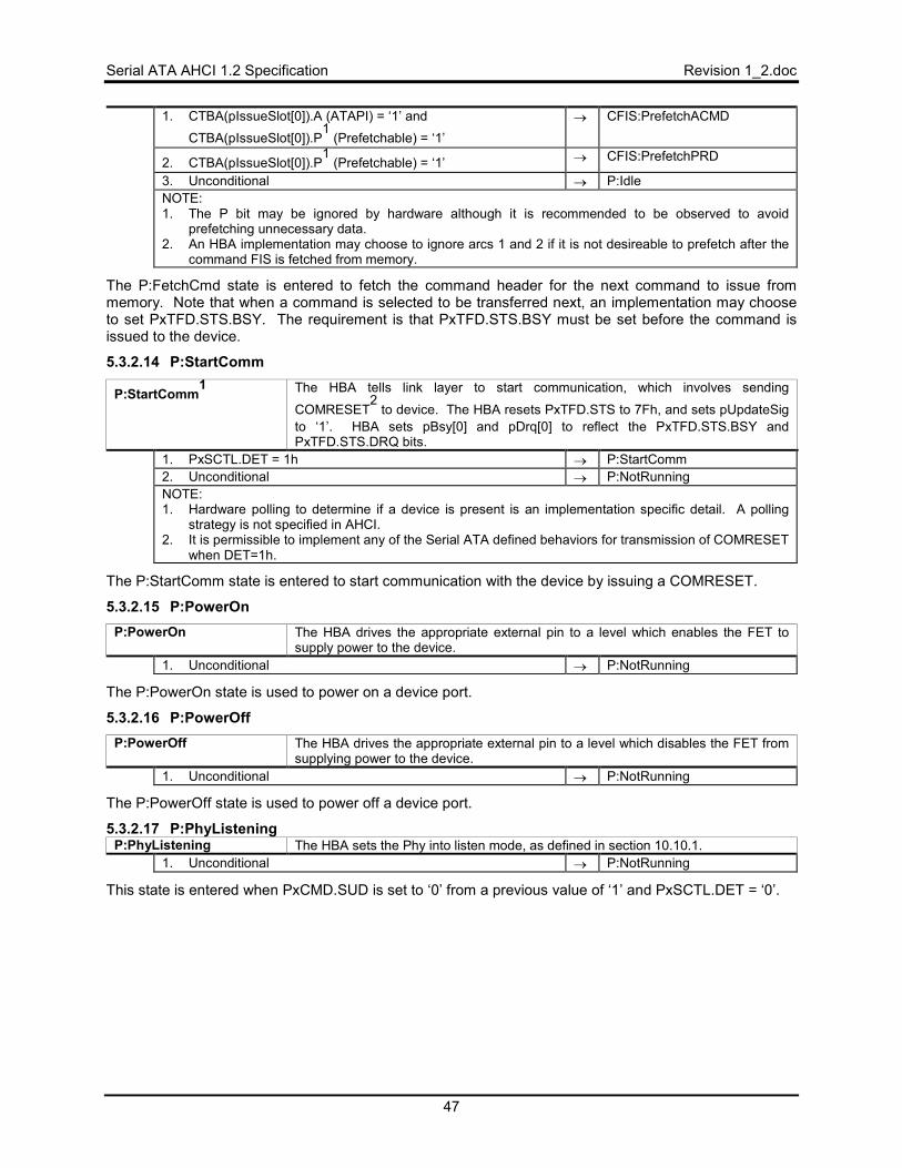
Serial ATA AHCI 1.2 Specification Revision 1_2.doc
47
1. CTBA(pIssueSlot[0]).A (ATAPI) = ‘1’ and CTBA(pIssueSlot[0]).P
1(Prefetchable) = ‘1’
→ CFIS:PrefetchACMD
2. CTBA(pIssueSlot[0]).P1
(Prefetchable) = ‘1’ → CFIS:PrefetchPRD
3. Unconditional → P:Idle NOTE: 1. The P bit may be ignored by hardware although it is recommended to be observed to avoid
prefetching unnecessary data. 2. An HBA implementation may choose to ignore arcs 1 and 2 if it is not desireable to prefetch after the
command FIS is fetched from memory.
The P:FetchCmd state is entered to fetch the command header for the next command to issue from memory. Note that when a command is selected to be transferred next, an implementation may choose to set PxTFD.STS.BSY. The requirement is that PxTFD.STS.BSY must be set before the command is issued to the device.
5.3.2.14 P:StartComm
P:StartComm1 The HBA tells link layer to start communication, which involves sending
COMRESET2
to device. The HBA resets PxTFD.STS to 7Fh, and sets pUpdateSig to ‘1’. HBA sets pBsy[0] and pDrq[0] to reflect the PxTFD.STS.BSY and PxTFD.STS.DRQ bits.
1. PxSCTL.DET = 1h → P:StartComm 2. Unconditional → P:NotRunning NOTE: 1. Hardware polling to determine if a device is present is an implementation specific detail. A polling
strategy is not specified in AHCI. 2. It is permissible to implement any of the Serial ATA defined behaviors for transmission of COMRESET
when DET=1h.
The P:StartComm state is entered to start communication with the device by issuing a COMRESET.
5.3.2.15 P:PowerOn P:PowerOn The HBA drives the appropriate external pin to a level which enables the FET to
supply power to the device. 1. Unconditional → P:NotRunning
The P:PowerOn state is used to power on a device port.
5.3.2.16 P:PowerOff P:PowerOff The HBA drives the appropriate external pin to a level which disables the FET from
supplying power to the device. 1. Unconditional → P:NotRunning
The P:PowerOff state is used to power off a device port.
5.3.2.17 P:PhyListening P:PhyListening The HBA sets the Phy into listen mode, as defined in section 10.10.1.
1. Unconditional → P:NotRunning
This state is entered when PxCMD.SUD is set to ‘0’ from a previous value of ‘1’ and PxSCTL.DET = ‘0’.

Revision 1_2.doc Serial ATA AHCI 1.2 Specification
48
5.3.3 FIS-based Switching Specific States
5.3.3.1 FB:Idle FB:Idle HBA sets PxCMD.CR to ‘1’.
1. PxSSTS.DET != 3h → P:NotRunning 2. pCmdToIssue = ‘0’ and there is a device that a command
pending in the command list can be issued to1→ FB:SelectDevice
3. Data FIS received → DR:Entry 4. Non-Data FIS received → NDR:Entry 5. pCmdToIssue = ‘1’ and pDmaXferCnt = ‘0’ → CFIS:Xmit 6. Link layer has negotiated to low power state based on device
power management request → PM:LowPower
7. PxCMD.ICC written → PM:ICC 8. Else → FB:Idle NOTE: 1. The HBA shall only issue a command to a device if the corresponding pDmXferCnt, pBsy, and pDrq
variables are zero.
The FB:Idle state is entered when in FIS-based switching operation to determine the next thing to do.
5.3.3.2 FB:SelectDevice FB:SelectDevice HBA selects a device, pDevIssue, to issue a command to that has pBsy[pDevIssue]
= ‘0’, pDrq[pDevIssue] = ‘0’ and has a command to be issued in the command list (a PxCI bit is ‘1’ for this device).
1. Unconditional → FB:SelectCmd
The FB:SelectDevice state is entered to select the device to issue a command to next. The device selected shall have BSY and DRQ cleared to zero and a command pending in the list. Devices shall be selected in a manner such that starvation of any device is avoided. In addition, selection of a command issued to the control port shall be preferred.
5.3.3.3 FB:SelectCmd FB:SelectCmd HBA selects the command to issue for device pDevIssue that has the PxCI bit set to
‘1’ longer than any other command pending to be issued to that device. HBA sets the variable pSlotLoc to the slot location of the command selected. Command ordering is per requirements in section 9.3.2.
1. Unconditional → FB:FetchCmd
The FB:SelectCmd state is entered to selected the next command to issue to device pDevIssue. The command selected shall be the oldest command yet to be issued (i.e. the command that had its PxCI bit set first). If multiple commands were issued on the same write to PxCI, the HBA may select the command to issue arbitrarily from amongst those commands when they are the oldest.
5.3.3.4 FB:FetchCmd FB:FetchCmd The HBA performs the following actions in the order specified:
1. HBA fetches command header from PxCLB[CH(pSlotLoc)] 2. HBA sets pIssueSlot[pDevIssue] to pSlotLoc. 3. HBA sets pCmdToIssue = ‘1’
1. Unconditional → FB:Idle
The FB:FetchCmd state is entered to fetch the command FIS to transmit next from memory. When using FIS-based switching, the prefetch bit in the command header shall be zero. Thus, there are no transitions for prefetching PRDs, data, or the ATAPI command. An implementation may choose to prefetch in a design specific manner. Note that when a command is selected to be transferred next, an implementation may choose to set pBsy[pSlotLoc] to ‘1’. The requirement is that pBsy[pSlotLoc] must be set before the command is issued to the device.
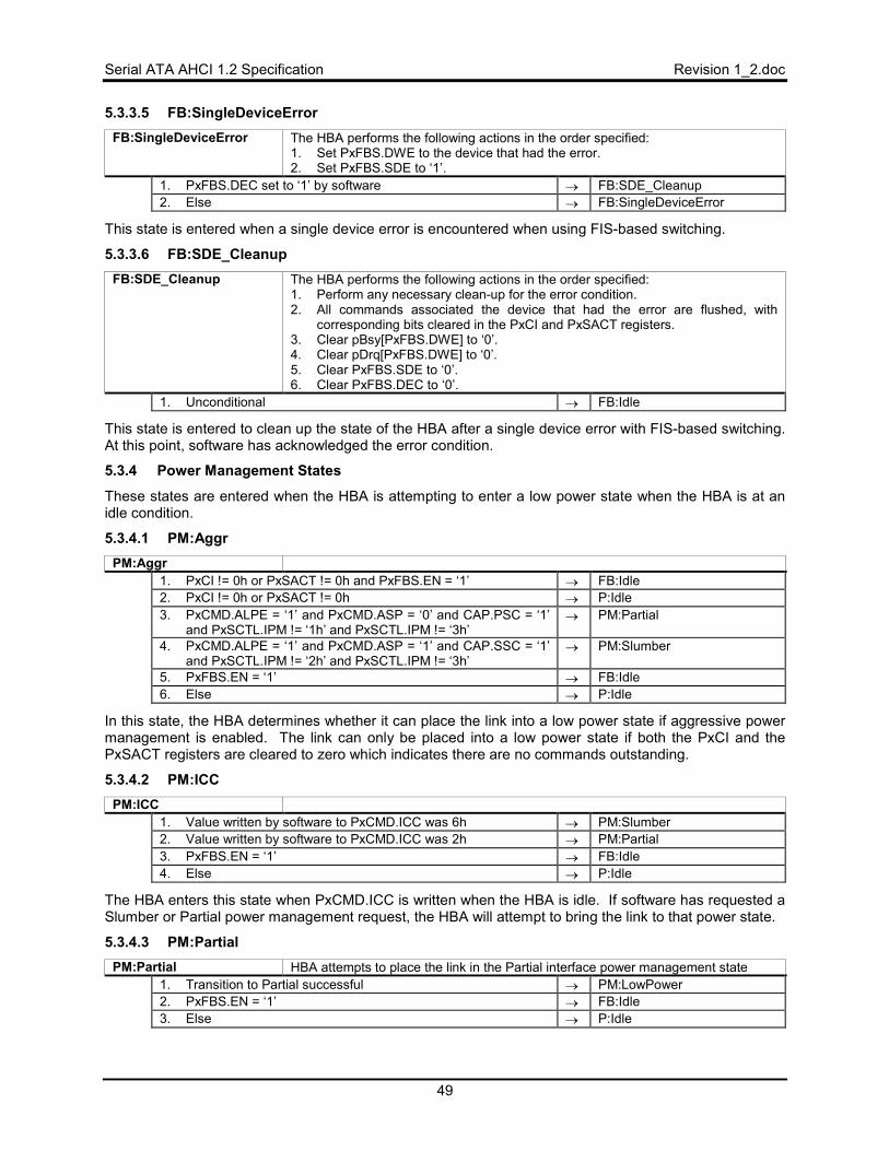
Serial ATA AHCI 1.2 Specification Revision 1_2.doc
49
5.3.3.5 FB:SingleDeviceError FB:SingleDeviceError The HBA performs the following actions in the order specified:
1. Set PxFBS.DWE to the device that had the error. 2. Set PxFBS.SDE to ‘1’.
1. PxFBS.DEC set to ‘1’ by software → FB:SDE_Cleanup 2. Else → FB:SingleDeviceError
This state is entered when a single device error is encountered when using FIS-based switching.
5.3.3.6 FB:SDE_Cleanup FB:SDE_Cleanup The HBA performs the following actions in the order specified:
1. Perform any necessary clean-up for the error condition. 2. All commands associated the device that had the error are flushed, with
corresponding bits cleared in the PxCI and PxSACT registers. 3. Clear pBsy[PxFBS.DWE] to ‘0’. 4. Clear pDrq[PxFBS.DWE] to ‘0’. 5. Clear PxFBS.SDE to ‘0’. 6. Clear PxFBS.DEC to ‘0’.
1. Unconditional → FB:Idle
This state is entered to clean up the state of the HBA after a single device error with FIS-based switching. At this point, software has acknowledged the error condition.
5.3.4 Power Management States
These states are entered when the HBA is attempting to enter a low power state when the HBA is at an idle condition.
5.3.4.1 PM:Aggr PM:Aggr
1. PxCI != 0h or PxSACT != 0h and PxFBS.EN = ‘1’ → FB:Idle 2. PxCI != 0h or PxSACT != 0h → P:Idle 3. PxCMD.ALPE = ‘1’ and PxCMD.ASP = ‘0’ and CAP.PSC = ‘1’
and PxSCTL.IPM != ‘1h’ and PxSCTL.IPM != ‘3h’ → PM:Partial
4. PxCMD.ALPE = ‘1’ and PxCMD.ASP = ‘1’ and CAP.SSC = ‘1’ and PxSCTL.IPM != ‘2h’ and PxSCTL.IPM != ‘3h’
→ PM:Slumber
5. PxFBS.EN = ‘1’ → FB:Idle 6. Else → P:Idle
In this state, the HBA determines whether it can place the link into a low power state if aggressive power management is enabled. The link can only be placed into a low power state if both the PxCI and the PxSACT registers are cleared to zero which indicates there are no commands outstanding.
5.3.4.2 PM:ICC PM:ICC
1. Value written by software to PxCMD.ICC was 6h → PM:Slumber 2. Value written by software to PxCMD.ICC was 2h → PM:Partial 3. PxFBS.EN = ‘1’ → FB:Idle 4. Else → P:Idle
The HBA enters this state when PxCMD.ICC is written when the HBA is idle. If software has requested a Slumber or Partial power management request, the HBA will attempt to bring the link to that power state.
5.3.4.3 PM:Partial PM:Partial HBA attempts to place the link in the Partial interface power management state
1. Transition to Partial successful → PM:LowPower 2. PxFBS.EN = ‘1’ → FB:Idle 3. Else → P:Idle
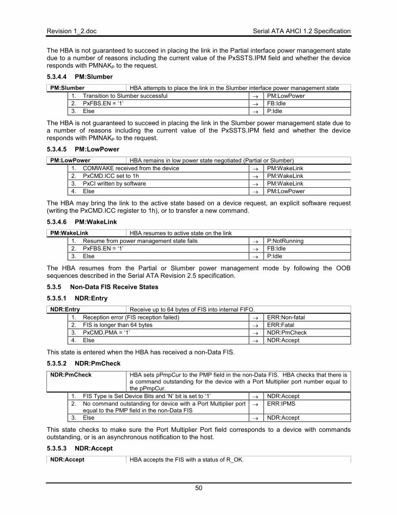
Revision 1_2.doc Serial ATA AHCI 1.2 Specification
50
The HBA is not guaranteed to succeed in placing the link in the Partial interface power management state due to a number of reasons including the current value of the PxSSTS.IPM field and whether the device responds with PMNAKP to the request.
5.3.4.4 PM:Slumber PM:Slumber HBA attempts to place the link in the Slumber interface power management state
1. Transition to Slumber successful → PM:LowPower 2. PxFBS.EN = ‘1’ → FB:Idle 3. Else → P:Idle
The HBA is not guaranteed to succeed in placing the link in the Slumber power management state due to a number of reasons including the current value of the PxSSTS.IPM field and whether the device responds with PMNAKP to the request.
5.3.4.5 PM:LowPower PM:LowPower HBA remains in low power state negotiated (Partial or Slumber)
1. COMWAKE received from the device → PM:WakeLink 2. PxCMD.ICC set to 1h → PM:WakeLink 3. PxCI written by software → PM:WakeLink 4. Else → PM:LowPower
The HBA may bring the link to the active state based on a device request, an explicit software request (writing the PxCMD.ICC register to 1h), or to transfer a new command.
5.3.4.6 PM:WakeLink PM:WakeLink HBA resumes to active state on the link
1. Resume from power management state fails → P:NotRunning 2. PxFBS.EN = ‘1’ → FB:Idle 3. Else → P:Idle
The HBA resumes from the Partial or Slumber power management mode by following the OOB sequences described in the Serial ATA Revision 2.5 specification.
5.3.5 Non-Data FIS Receive States
5.3.5.1 NDR:Entry NDR:Entry Receive up to 64 bytes of FIS into internal FIFO.
1. Reception error (FIS reception failed) → ERR:Non-fatal 2. FIS is longer than 64 bytes → ERR:Fatal 3. PxCMD.PMA = ‘1’ → NDR:PmCheck 4. Else → NDR:Accept
This state is entered when the HBA has received a non-Data FIS.
5.3.5.2 NDR:PmCheck NDR:PmCheck HBA sets pPmpCur to the PMP field in the non-Data FIS. HBA checks that there is
a command outstanding for the device with a Port Multiplier port number equal to the pPmpCur.
1. FIS Type is Set Device Bits and ‘N’ bit is set to ‘1’ → NDR:Accept 2. No command outstanding for device with a Port Multiplier port
equal to the PMP field in the non-Data FIS → ERR:IPMS
3. Else → NDR:Accept
This state checks to make sure the Port Multiplier Port field corresponds to a device with commands outstanding, or is an asynchronous notification to the host.
5.3.5.3 NDR:Accept NDR:Accept HBA accepts the FIS with a status of R_OK.
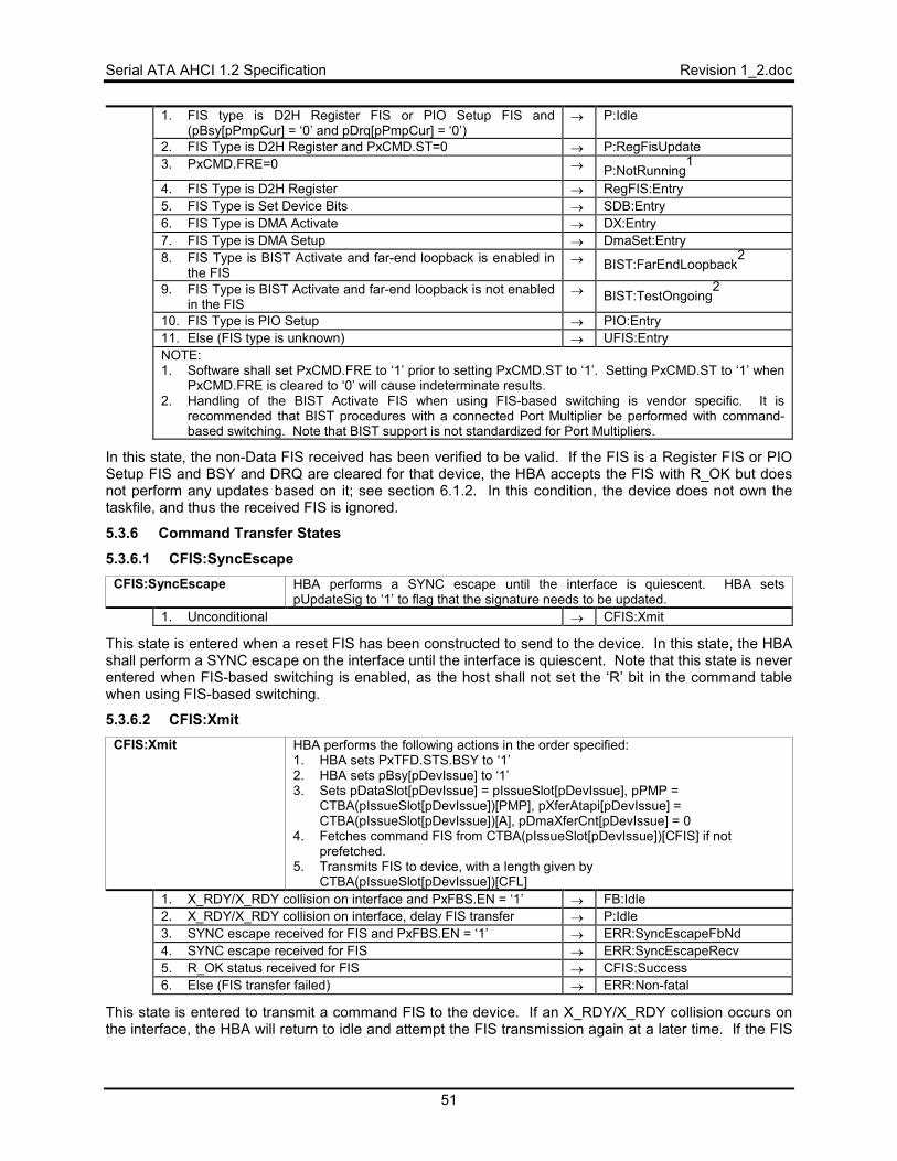
Serial ATA AHCI 1.2 Specification Revision 1_2.doc
51
1. FIS type is D2H Register FIS or PIO Setup FIS and (pBsy[pPmpCur] = ‘0’ and pDrq[pPmpCur] = ‘0’)
→ P:Idle
2. FIS Type is D2H Register and PxCMD.ST=0 → P:RegFisUpdate 3. PxCMD.FRE=0 → P:NotRunning
1
4. FIS Type is D2H Register → RegFIS:Entry 5. FIS Type is Set Device Bits → SDB:Entry 6. FIS Type is DMA Activate → DX:Entry 7. FIS Type is DMA Setup → DmaSet:Entry 8. FIS Type is BIST Activate and far-end loopback is enabled in
the FIS → BIST:FarEndLoopback
2
9. FIS Type is BIST Activate and far-end loopback is not enabled in the FIS
→ BIST:TestOngoing2
10. FIS Type is PIO Setup → PIO:Entry 11. Else (FIS type is unknown) → UFIS:Entry NOTE: 1. Software shall set PxCMD.FRE to ‘1’ prior to setting PxCMD.ST to ‘1’. Setting PxCMD.ST to ‘1’ when
PxCMD.FRE is cleared to ‘0’ will cause indeterminate results. 2. Handling of the BIST Activate FIS when using FIS-based switching is vendor specific. It is
recommended that BIST procedures with a connected Port Multiplier be performed with command-based switching. Note that BIST support is not standardized for Port Multipliers.
In this state, the non-Data FIS received has been verified to be valid. If the FIS is a Register FIS or PIO Setup FIS and BSY and DRQ are cleared for that device, the HBA accepts the FIS with R_OK but does not perform any updates based on it; see section 6.1.2. In this condition, the device does not own the taskfile, and thus the received FIS is ignored.
5.3.6 Command Transfer States
5.3.6.1 CFIS:SyncEscape CFIS:SyncEscape HBA performs a SYNC escape until the interface is quiescent. HBA sets
pUpdateSig to ‘1’ to flag that the signature needs to be updated. 1. Unconditional → CFIS:Xmit
This state is entered when a reset FIS has been constructed to send to the device. In this state, the HBA shall perform a SYNC escape on the interface until the interface is quiescent. Note that this state is never entered when FIS-based switching is enabled, as the host shall not set the ‘R’ bit in the command table when using FIS-based switching.
5.3.6.2 CFIS:Xmit CFIS:Xmit HBA performs the following actions in the order specified:
1. HBA sets PxTFD.STS.BSY to ‘1’ 2. HBA sets pBsy[pDevIssue] to ‘1’ 3. Sets pDataSlot[pDevIssue] = pIssueSlot[pDevIssue], pPMP =
CTBA(pIssueSlot[pDevIssue])[PMP], pXferAtapi[pDevIssue] = CTBA(pIssueSlot[pDevIssue])[A], pDmaXferCnt[pDevIssue] = 0
4. Fetches command FIS from CTBA(pIssueSlot[pDevIssue])[CFIS] if not prefetched.
5. Transmits FIS to device, with a length given by CTBA(pIssueSlot[pDevIssue])[CFL]
1. X_RDY/X_RDY collision on interface and PxFBS.EN = ‘1’ → FB:Idle 2. X_RDY/X_RDY collision on interface, delay FIS transfer → P:Idle 3. SYNC escape received for FIS and PxFBS.EN = ‘1’ → ERR:SyncEscapeFbNd 4. SYNC escape received for FIS → ERR:SyncEscapeRecv 5. R_OK status received for FIS → CFIS:Success 6. Else (FIS transfer failed) → ERR:Non-fatal
This state is entered to transmit a command FIS to the device. If an X_RDY/X_RDY collision occurs on the interface, the HBA will return to idle and attempt the FIS transmission again at a later time. If the FIS
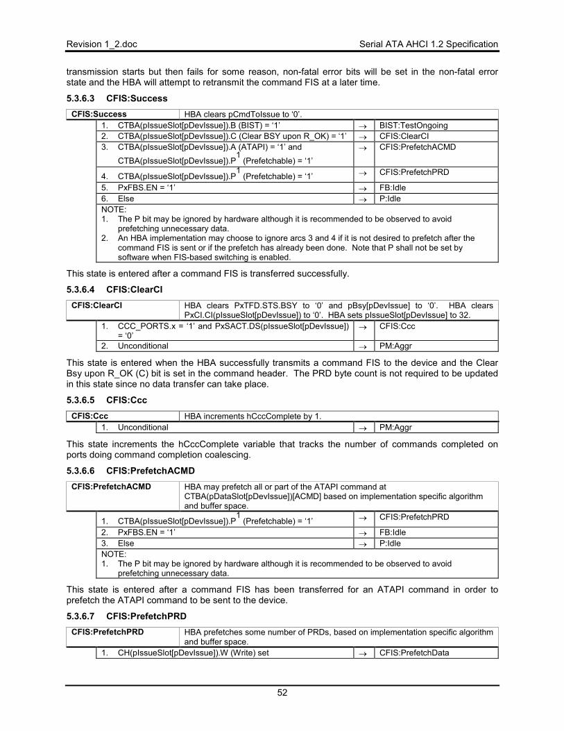
Revision 1_2.doc Serial ATA AHCI 1.2 Specification
52
transmission starts but then fails for some reason, non-fatal error bits will be set in the non-fatal error state and the HBA will attempt to retransmit the command FIS at a later time.
5.3.6.3 CFIS:Success CFIS:Success HBA clears pCmdToIssue to ‘0’.
1. CTBA(pIssueSlot[pDevIssue]).B (BIST) = ‘1’ → BIST:TestOngoing 2. CTBA(pIssueSlot[pDevIssue]).C (Clear BSY upon R_OK) = ‘1’ → CFIS:ClearCI 3. CTBA(pIssueSlot[pDevIssue]).A (ATAPI) = ‘1’ and
CTBA(pIssueSlot[pDevIssue]).P1
(Prefetchable) = ‘1’ → CFIS:PrefetchACMD
4. CTBA(pIssueSlot[pDevIssue]).P1
(Prefetchable) = ‘1’ → CFIS:PrefetchPRD
5. PxFBS.EN = ‘1’ → FB:Idle 6. Else → P:Idle NOTE: 1. The P bit may be ignored by hardware although it is recommended to be observed to avoid
prefetching unnecessary data. 2. An HBA implementation may choose to ignore arcs 3 and 4 if it is not desired to prefetch after the
command FIS is sent or if the prefetch has already been done. Note that P shall not be set by software when FIS-based switching is enabled.
This state is entered after a command FIS is transferred successfully.
5.3.6.4 CFIS:ClearCI CFIS:ClearCI HBA clears PxTFD.STS.BSY to ‘0’ and pBsy[pDevIssue] to ‘0’. HBA clears
PxCI.CI(pIssueSlot[pDevIssue]) to ‘0’. HBA sets pIssueSlot[pDevIssue] to 32. 1. CCC_PORTS.x = ‘1’ and PxSACT.DS(pIssueSlot[pDevIssue])
= ‘0’ → CFIS:Ccc
2. Unconditional → PM:Aggr
This state is entered when the HBA successfully transmits a command FIS to the device and the Clear Bsy upon R_OK (C) bit is set in the command header. The PRD byte count is not required to be updated in this state since no data transfer can take place.
5.3.6.5 CFIS:Ccc CFIS:Ccc HBA increments hCccComplete by 1.
1. Unconditional → PM:Aggr
This state increments the hCccComplete variable that tracks the number of commands completed on ports doing command completion coalescing.
5.3.6.6 CFIS:PrefetchACMD CFIS:PrefetchACMD HBA may prefetch all or part of the ATAPI command at
CTBA(pDataSlot[pDevIssue])[ACMD] based on implementation specific algorithm and buffer space.
1. CTBA(pIssueSlot[pDevIssue]).P1
(Prefetchable) = ‘1’ → CFIS:PrefetchPRD
2. PxFBS.EN = ‘1’ → FB:Idle 3. Else → P:Idle NOTE: 1. The P bit may be ignored by hardware although it is recommended to be observed to avoid
prefetching unnecessary data.
This state is entered after a command FIS has been transferred for an ATAPI command in order to prefetch the ATAPI command to be sent to the device.
5.3.6.7 CFIS:PrefetchPRD CFIS:PrefetchPRD HBA prefetches some number of PRDs, based on implementation specific algorithm
and buffer space. 1. CH(pIssueSlot[pDevIssue]).W (Write) set → CFIS:PrefetchData
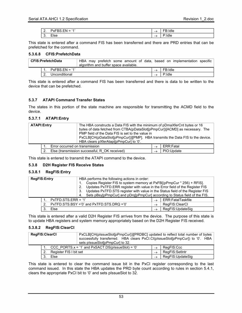
Serial ATA AHCI 1.2 Specification Revision 1_2.doc
53
2. PxFBS.EN = ‘1’ → FB:Idle 3. Else → P:Idle
This state is entered after a command FIS has been transferred and there are PRD entries that can be prefetched for the command.
5.3.6.8 CFIS:PrefetchData CFIS:PrefetchData HBA may prefetch some amount of data, based on implementation specific
algorithm and buffer space available. 1. PxFBS.EN = ‘1’ → FB:Idle 2. Unconditional → P:Idle
This state is entered after a command FIS has been transferred and there is data to be written to the device that can be prefetched.
5.3.7 ATAPI Command Transfer States
The states in this portion of the state machine are responsible for transmitting the ACMD field to the device.
5.3.7.1 ATAPI:Entry ATAPI:Entry The HBA constructs a Data FIS with the minimum of pDmaXferCnt bytes or 16
bytes of data fetched from CTBA(pDataSlot[pPmpCur])[ACMD] as necessary. The PMP field of the Data FIS is set to the value in PxCLB[CH(pDataSlot[pPmpCur])][PMP]. HBA transmits the Data FIS to the device. HBA clears pXferAtapi[pPmpCur] to ‘0’.
1. Error occurred on transmission → ERR:Fatal 2. Else (transmission successful, R_OK received) → PIO:Update
This state is entered to transmit the ATAPI command to the device.
5.3.8 D2H Register FIS Receive States
5.3.8.1 RegFIS:Entry RegFIS:Entry HBA performs the following actions in order:
1. Copies Register FIS to system memory at PxFB[(pPmpCur * 256) + RFIS]. 2. Updates PxTFD.ERR register with value in the Error field of the Register FIS 3. Updates PxTFD.STS register with value in the Status field of the Register FIS 4. Sets pBsy[pPmpCur] and pDrq[pPmpCur] according to Status field of the FIS.
1. PxTFD.STS.ERR = ‘1’ → ERR:FatalTaskfile 2. PxTFD.STS.BSY =’0’ and PxTFD.STS.DRQ =’0’ → RegFIS:ClearCI 3. Else → RegFIS:UpdateSig
This state is entered after a valid D2H Register FIS arrives from the device. The purpose of this state is to update HBA registers and system memory appropriately based on the D2H Register FIS received.
5.3.8.2 RegFIS:ClearCI RegFIS:ClearCI PxCLB[CH(pIssueSlot[pPmpCur])][PRDBC] updated to reflect total number of bytes
successfully transferred. HBA clears PxCI.CI(pIssueSlot[pPmpCur]) to ‘0’. HBA sets pIssueSlot[pPmpCur] to 32.
1. CCC_PORTS.x = ‘1’ and PxSACT.DS(pIssueSlot) = ‘0’ → RegFIS:Ccc 2. Register FIS I bit set → RegFIS:SetIntr 3. Else → RegFIS:UpdateSig
This state is entered to clear the command issue bit in the PxCI register corresponding to the last command issued. In this state the HBA updates the PRD byte count according to rules in section 5.4.1, clears the appropriate PxCI bit to ‘0’ and sets pIssueSlot to 32.
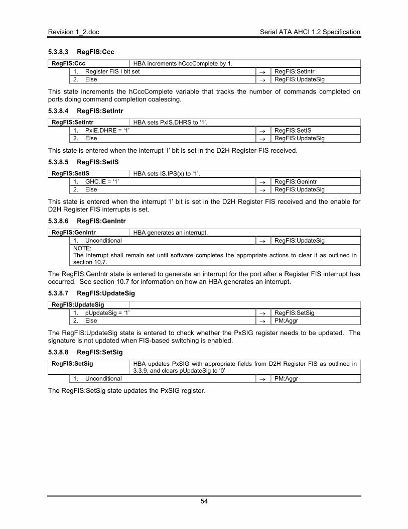
Revision 1_2.doc Serial ATA AHCI 1.2 Specification
54
5.3.8.3 RegFIS:Ccc RegFIS:Ccc HBA increments hCccComplete by 1.
1. Register FIS I bit set → RegFIS:SetIntr 2. Else → RegFIS:UpdateSig
This state increments the hCccComplete variable that tracks the number of commands completed on ports doing command completion coalescing.
5.3.8.4 RegFIS:SetIntr RegFIS:SetIntr HBA sets PxIS.DHRS to ‘1’.
1. PxIE.DHRE = ‘1’ → RegFIS:SetIS 2. Else → RegFIS:UpdateSig
This state is entered when the interrupt ‘I’ bit is set in the D2H Register FIS received.
5.3.8.5 RegFIS:SetIS RegFIS:SetIS HBA sets IS.IPS(x) to ‘1’.
1. GHC.IE = ‘1’ → RegFIS:GenIntr 2. Else → RegFIS:UpdateSig
This state is entered when the interrupt ‘I’ bit is set in the D2H Register FIS received and the enable for D2H Register FIS interrupts is set.
5.3.8.6 RegFIS:GenIntr RegFIS:GenIntr HBA generates an interrupt.
1. Unconditional → RegFIS:UpdateSig NOTE: The interrupt shall remain set until software completes the appropriate actions to clear it as outlined in section 10.7.
The RegFIS:GenIntr state is entered to generate an interrupt for the port after a Register FIS interrupt has occurred. See section 10.7 for information on how an HBA generates an interrupt.
5.3.8.7 RegFIS:UpdateSig RegFIS:UpdateSig
1. pUpdateSig = ‘1’ → RegFIS:SetSig 2. Else → PM:Aggr
The RegFIS:UpdateSig state is entered to check whether the PxSIG register needs to be updated. The signature is not updated when FIS-based switching is enabled.
5.3.8.8 RegFIS:SetSig RegFIS:SetSig HBA updates PxSIG with appropriate fields from D2H Register FIS as outlined in
3.3.9, and clears pUpdateSig to ‘0’ 1. Unconditional → PM:Aggr
The RegFIS:SetSig state updates the PxSIG register.
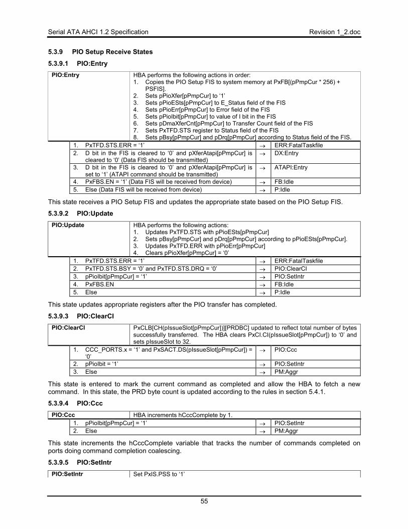
Serial ATA AHCI 1.2 Specification Revision 1_2.doc
55
5.3.9 PIO Setup Receive States
5.3.9.1 PIO:Entry PIO:Entry HBA performs the following actions in order:
1. Copies the PIO Setup FIS to system memory at PxFB[(pPmpCur * 256) + PSFIS].
2. Sets pPioXfer[pPmpCur] to ‘1’ 3. Sets pPioESts[pPmpCur] to E_Status field of the FIS 4. Sets pPioErr[pPmpCur] to Error field of the FIS 5. Sets pPioIbit[pPmpCur] to value of I bit in the FIS 6. Sets pDmaXferCnt[pPmpCur] to Transfer Count field of the FIS 7. Sets PxTFD.STS register to Status field of the FIS 8. Sets pBsy[pPmpCur] and pDrq[pPmpCur] according to Status field of the FIS.
1. PxTFD.STS.ERR = ‘1’ → ERR:FatalTaskfile 2. D bit in the FIS is cleared to ‘0’ and pXferAtapi[pPmpCur] is
cleared to ‘0’ (Data FIS should be transmitted) → DX:Entry
3. D bit in the FIS is cleared to ‘0’ and pXferAtapi[pPmpCur] is set to ‘1’ (ATAPI command should be transmitted)
→ ATAPI:Entry
4. PxFBS.EN = ‘1’ (Data FIS will be received from device) → FB:Idle 5. Else (Data FIS will be received from device) → P:Idle
This state receives a PIO Setup FIS and updates the appropriate state based on the PIO Setup FIS.
5.3.9.2 PIO:Update PIO:Update HBA performs the following actions:
1. Updates PxTFD.STS with pPioESts[pPmpCur] 2. Sets pBsy[pPmpCur] and pDrq[pPmpCur] according to pPioESts[pPmpCur]. 3. Updates PxTFD.ERR with pPioErr[pPmpCur] 4. Clears pPioXfer[pPmpCur] = ‘0’
1. PxTFD.STS.ERR = ‘1’ → ERR:FatalTaskfile 2. PxTFD.STS.BSY = ‘0’ and PxTFD.STS.DRQ = ‘0’ → PIO:ClearCI 3. pPioIbit[pPmpCur] = ‘1’ → PIO:SetIntr 4. PxFBS.EN → FB:Idle 5. Else → P:Idle
This state updates appropriate registers after the PIO transfer has completed.
5.3.9.3 PIO:ClearCI PIO:ClearCI PxCLB[CH(pIssueSlot[pPmpCur])][PRDBC] updated to reflect total number of bytes
successfully transferred. The HBA clears PxCI.CI(pIssueSlot[pPmpCur]) to ‘0’ and sets pIssueSlot to 32.
1. CCC_PORTS.x = ‘1’ and PxSACT.DS(pIssueSlot[pPmpCur]) = ‘0’
→ PIO:Ccc
2. pPioIbit = ‘1’ → PIO:SetIntr 3. Else → PM:Aggr
This state is entered to mark the current command as completed and allow the HBA to fetch a new command. In this state, the PRD byte count is updated according to the rules in section 5.4.1.
5.3.9.4 PIO:Ccc PIO:Ccc HBA increments hCccComplete by 1.
1. pPioIbit[pPmpCur] = ‘1’ → PIO:SetIntr 2. Else → PM:Aggr
This state increments the hCccComplete variable that tracks the number of commands completed on ports doing command completion coalescing.
5.3.9.5 PIO:SetIntr PIO:SetIntr Set PxIS.PSS to ‘1’
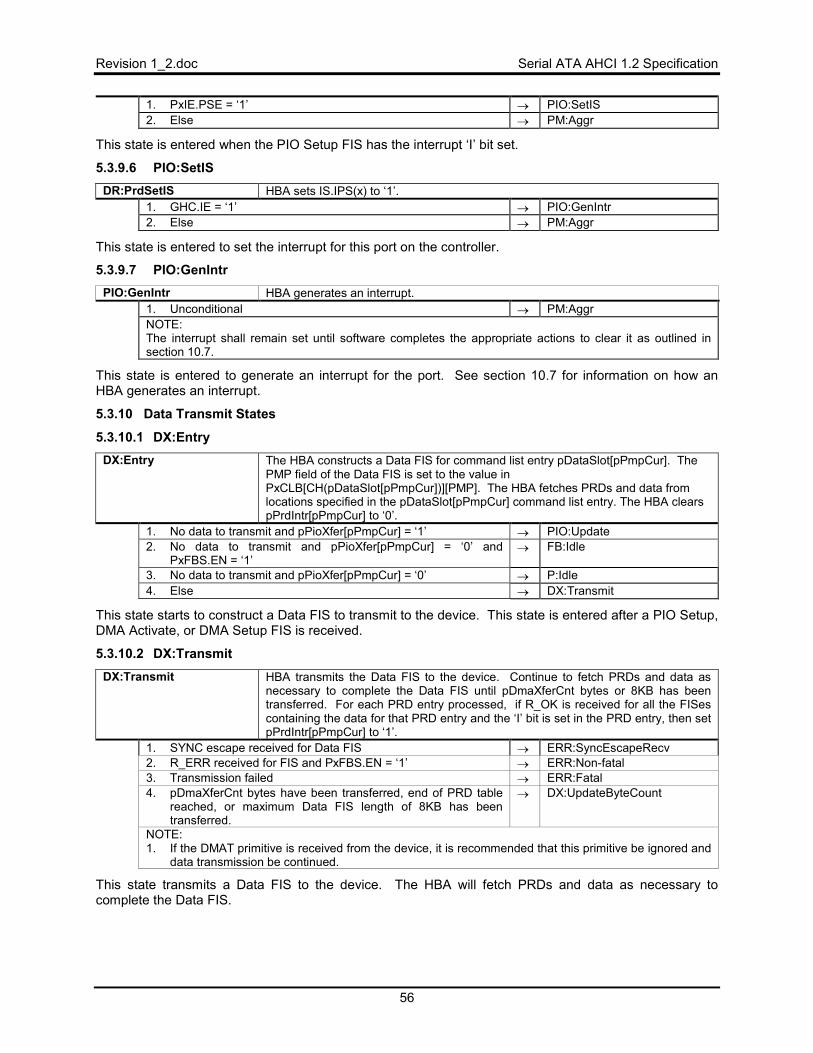
Revision 1_2.doc Serial ATA AHCI 1.2 Specification
56
1. PxIE.PSE = ‘1’ → PIO:SetIS 2. Else → PM:Aggr
This state is entered when the PIO Setup FIS has the interrupt ‘I’ bit set.
5.3.9.6 PIO:SetIS DR:PrdSetIS HBA sets IS.IPS(x) to ‘1’.
1. GHC.IE = ‘1’ → PIO:GenIntr 2. Else → PM:Aggr
This state is entered to set the interrupt for this port on the controller.
5.3.9.7 PIO:GenIntr PIO:GenIntr HBA generates an interrupt.
1. Unconditional → PM:Aggr NOTE: The interrupt shall remain set until software completes the appropriate actions to clear it as outlined in section 10.7.
This state is entered to generate an interrupt for the port. See section 10.7 for information on how an HBA generates an interrupt.
5.3.10 Data Transmit States
5.3.10.1 DX:Entry DX:Entry The HBA constructs a Data FIS for command list entry pDataSlot[pPmpCur]. The
PMP field of the Data FIS is set to the value in PxCLB[CH(pDataSlot[pPmpCur])][PMP]. The HBA fetches PRDs and data from locations specified in the pDataSlot[pPmpCur] command list entry. The HBA clears pPrdIntr[pPmpCur] to ‘0’.
1. No data to transmit and pPioXfer[pPmpCur] = ‘1’ → PIO:Update 2. No data to transmit and pPioXfer[pPmpCur] = ‘0’ and
PxFBS.EN = ‘1’ → FB:Idle
3. No data to transmit and pPioXfer[pPmpCur] = ‘0’ → P:Idle 4. Else → DX:Transmit
This state starts to construct a Data FIS to transmit to the device. This state is entered after a PIO Setup, DMA Activate, or DMA Setup FIS is received.
5.3.10.2 DX:Transmit DX:Transmit HBA transmits the Data FIS to the device. Continue to fetch PRDs and data as
necessary to complete the Data FIS until pDmaXferCnt bytes or 8KB has been transferred. For each PRD entry processed, if R_OK is received for all the FISes containing the data for that PRD entry and the ‘I’ bit is set in the PRD entry, then set pPrdIntr[pPmpCur] to ‘1’.
1. SYNC escape received for Data FIS → ERR:SyncEscapeRecv 2. R_ERR received for FIS and PxFBS.EN = ‘1’ → ERR:Non-fatal 3. Transmission failed → ERR:Fatal 4. pDmaXferCnt bytes have been transferred, end of PRD table
reached, or maximum Data FIS length of 8KB has been transferred.
→ DX:UpdateByteCount
NOTE: 1. If the DMAT primitive is received from the device, it is recommended that this primitive be ignored and
data transmission be continued.
This state transmits a Data FIS to the device. The HBA will fetch PRDs and data as necessary to complete the Data FIS.
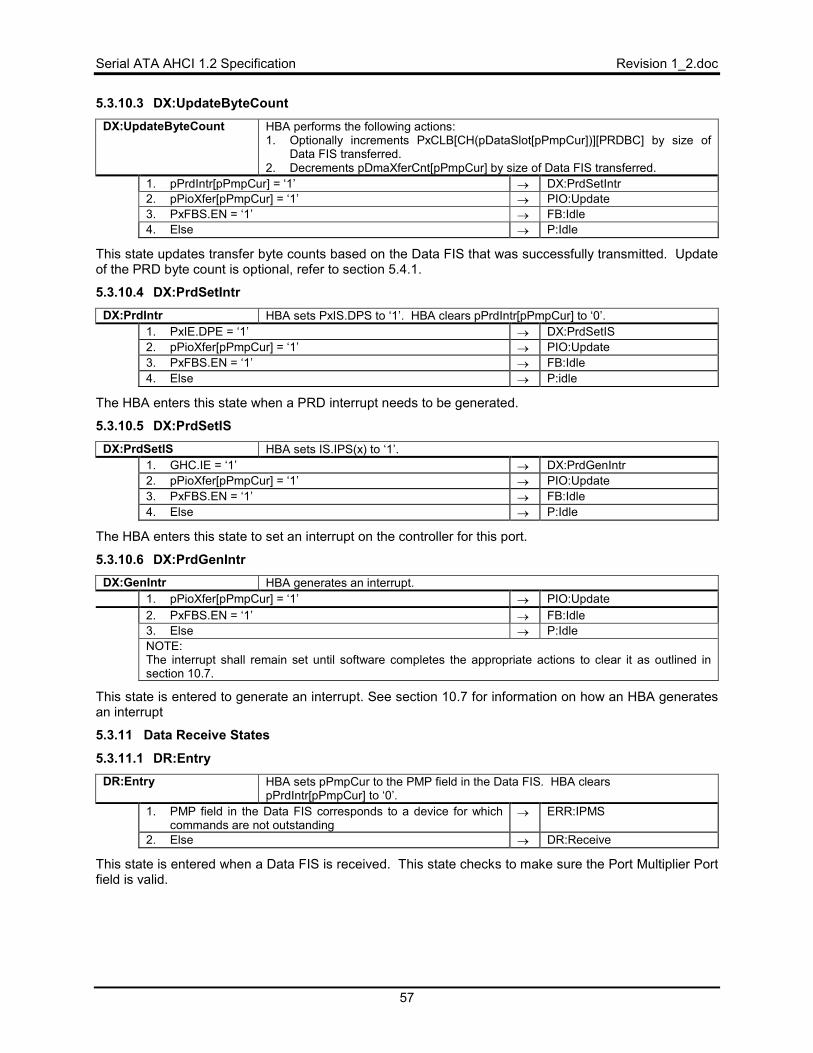
Serial ATA AHCI 1.2 Specification Revision 1_2.doc
57
5.3.10.3 DX:UpdateByteCount DX:UpdateByteCount HBA performs the following actions:
1. Optionally increments PxCLB[CH(pDataSlot[pPmpCur])][PRDBC] by size of Data FIS transferred.
2. Decrements pDmaXferCnt[pPmpCur] by size of Data FIS transferred. 1. pPrdIntr[pPmpCur] = ‘1’ → DX:PrdSetIntr 2. pPioXfer[pPmpCur] = ‘1’ → PIO:Update 3. PxFBS.EN = ‘1’ → FB:Idle 4. Else → P:Idle
This state updates transfer byte counts based on the Data FIS that was successfully transmitted. Update of the PRD byte count is optional, refer to section 5.4.1.
5.3.10.4 DX:PrdSetIntr DX:PrdIntr HBA sets PxIS.DPS to ‘1’. HBA clears pPrdIntr[pPmpCur] to ‘0’.
1. PxIE.DPE = ‘1’ → DX:PrdSetIS 2. pPioXfer[pPmpCur] = ‘1’ → PIO:Update 3. PxFBS.EN = ‘1’ → FB:Idle 4. Else → P:idle
The HBA enters this state when a PRD interrupt needs to be generated.
5.3.10.5 DX:PrdSetIS DX:PrdSetIS HBA sets IS.IPS(x) to ‘1’.
1. GHC.IE = ‘1’ → DX:PrdGenIntr 2. pPioXfer[pPmpCur] = ‘1’ → PIO:Update 3. PxFBS.EN = ‘1’ → FB:Idle 4. Else → P:Idle
The HBA enters this state to set an interrupt on the controller for this port.
5.3.10.6 DX:PrdGenIntr DX:GenIntr HBA generates an interrupt.
1. pPioXfer[pPmpCur] = ‘1’ → PIO:Update 2. PxFBS.EN = ‘1’ → FB:Idle 3. Else → P:Idle NOTE: The interrupt shall remain set until software completes the appropriate actions to clear it as outlined in section 10.7.
This state is entered to generate an interrupt. See section 10.7 for information on how an HBA generates an interrupt
5.3.11 Data Receive States
5.3.11.1 DR:Entry DR:Entry HBA sets pPmpCur to the PMP field in the Data FIS. HBA clears
pPrdIntr[pPmpCur] to ‘0’. 1. PMP field in the Data FIS corresponds to a device for which
commands are not outstanding → ERR:IPMS
2. Else → DR:Receive
This state is entered when a Data FIS is received. This state checks to make sure the Port Multiplier Port field is valid.
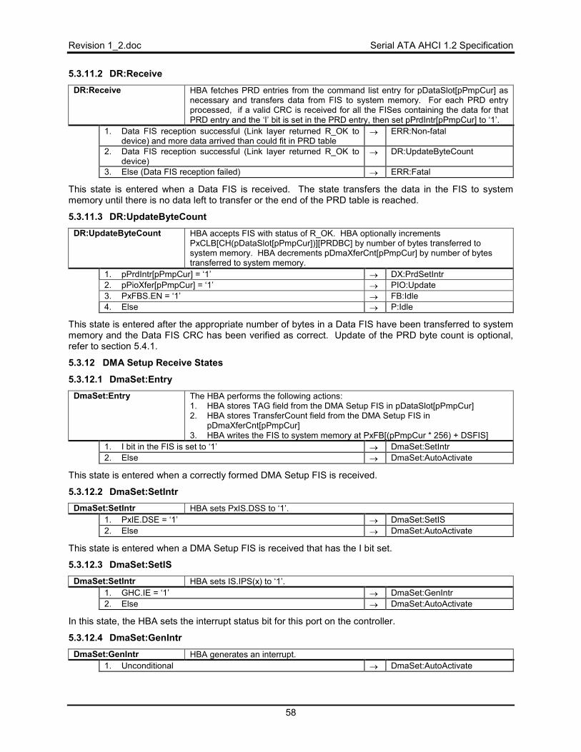
Revision 1_2.doc Serial ATA AHCI 1.2 Specification
58
5.3.11.2 DR:Receive DR:Receive HBA fetches PRD entries from the command list entry for pDataSlot[pPmpCur] as
necessary and transfers data from FIS to system memory. For each PRD entry processed, if a valid CRC is received for all the FISes containing the data for that PRD entry and the ‘I’ bit is set in the PRD entry, then set pPrdIntr[pPmpCur] to ‘1’.
1. Data FIS reception successful (Link layer returned R_OK to device) and more data arrived than could fit in PRD table
→ ERR:Non-fatal
2. Data FIS reception successful (Link layer returned R_OK to device)
→ DR:UpdateByteCount
3. Else (Data FIS reception failed) → ERR:Fatal
This state is entered when a Data FIS is received. The state transfers the data in the FIS to system memory until there is no data left to transfer or the end of the PRD table is reached.
5.3.11.3 DR:UpdateByteCount DR:UpdateByteCount HBA accepts FIS with status of R_OK. HBA optionally increments
PxCLB[CH(pDataSlot[pPmpCur])][PRDBC] by number of bytes transferred to system memory. HBA decrements pDmaXferCnt[pPmpCur] by number of bytes transferred to system memory.
1. pPrdIntr[pPmpCur] = ‘1’ → DX:PrdSetIntr 2. pPioXfer[pPmpCur] = ‘1’ → PIO:Update 3. PxFBS.EN = ‘1’ → FB:Idle 4. Else → P:Idle
This state is entered after the appropriate number of bytes in a Data FIS have been transferred to system memory and the Data FIS CRC has been verified as correct. Update of the PRD byte count is optional, refer to section 5.4.1.
5.3.12 DMA Setup Receive States
5.3.12.1 DmaSet:Entry DmaSet:Entry The HBA performs the following actions:
1. HBA stores TAG field from the DMA Setup FIS in pDataSlot[pPmpCur] 2. HBA stores TransferCount field from the DMA Setup FIS in
pDmaXferCnt[pPmpCur] 3. HBA writes the FIS to system memory at PxFB[(pPmpCur * 256) + DSFIS]
1. I bit in the FIS is set to ‘1’ → DmaSet:SetIntr 2. Else → DmaSet:AutoActivate
This state is entered when a correctly formed DMA Setup FIS is received.
5.3.12.2 DmaSet:SetIntr DmaSet:SetIntr HBA sets PxIS.DSS to ‘1’.
1. PxIE.DSE = ‘1’ → DmaSet:SetIS 2. Else → DmaSet:AutoActivate
This state is entered when a DMA Setup FIS is received that has the I bit set.
5.3.12.3 DmaSet:SetIS DmaSet:SetIntr HBA sets IS.IPS(x) to ‘1’.
1. GHC.IE = ‘1’ → DmaSet:GenIntr 2. Else → DmaSet:AutoActivate
In this state, the HBA sets the interrupt status bit for this port on the controller.
5.3.12.4 DmaSet:GenIntr DmaSet:GenIntr HBA generates an interrupt.
1. Unconditional → DmaSet:AutoActivate
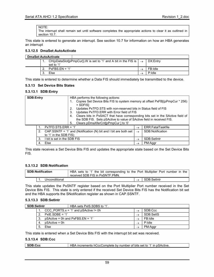
Serial ATA AHCI 1.2 Specification Revision 1_2.doc
59
NOTE: The interrupt shall remain set until software completes the appropriate actions to clear it as outlined in section 10.7.
This state is entered to generate an interrupt. See section 10.7 for information on how an HBA generates an interrupt
5.3.12.5 DmaSet:AutoActivate DmaSet:AutoActivate
1. CH(pDataSlot[pPmpCur]).W is set to ‘1’ and A bit in the FIS is set to ‘1’
→ DX:Entry
2. PxFBS.EN = ‘1’ → FB:Idle 3. Else → P:Idle
This state is entered to determine whether a Data FIS should immediately be transmitted to the device.
5.3.13 Set Device Bits States
5.3.13.1 SDB:Entry SDB:Entry HBA performs the following actions:
1. Copies Set Device Bits FIS to system memory at offset PxFB[(pPmpCur * 256) + SDFIS]
2. Updates PxTFD.STS with non-reserved bits in Status field of FIS 3. Updates PxTFD.ERR with Error field of FIS 4. Clears bits in PxSACT that have corresponding bits set in the SActive field of
the SDB FIS. Sets pSActive to value of SActive field in received FIS. 5. Clears pDmaXferCnt[pPmpCur ] to ‘0’
1. PxTFD.STS.ERR = ‘1’ → ERR:FatalTaskfile 2. CAP.SSNTF = ‘1’ and (Notification (N) bit and I bit are both set
to ‘1’ in the SDB FIS) → SDB:Notification
3. I bit is set in the SDB FIS → SDB:SetIntr 4. Else → PM:Aggr
This state receives a Set Device Bits FIS and updates the appropriate state based on the Set Device Bits FIS.
5.3.13.2 SDB:Notification SDB:Notification HBA sets to ‘1’ the bit corresponding to the Port Multiplier Port number in the
received SDB FIS in PxSNTF.PMN. 1. Unconditional → SDB:SetIntr
This state updates the PxSNTF register based on the Port Multiplier Port number received in the Set Device Bits FIS. This state is only entered if the received Set Device Bits FIS has the Notification bit set and the HBA supports the SNotification register as shown in CAP.SSNTF.
5.3.13.3 SDB:SetIntr SDB:SetIntr HBA sets PxIS.SDBS to ‘1’.
1. CCC_PORTS.x = ‘1’ and pSActive != 0h → SDB:Ccc 2. PxIE.SDBE = ‘1’ → SDB:SetIS 3. pSActive = 0h and PxFBS.EN = ‘1’ → FB:Idle 4. pSActive = 0h → P:Idle 5. Else → PM:Aggr
This state is entered when a Set Device Bits FIS with the interrupt bit set was received.
5.3.13.4 SDB:Ccc SDB:Ccc HBA increments hCccComplete by number of bits set to ‘1’ in pSActive.
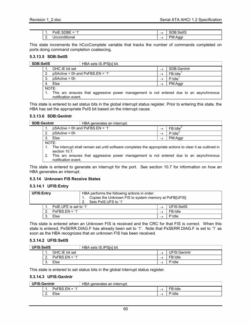
Revision 1_2.doc Serial ATA AHCI 1.2 Specification
60
1. PxIE.SDBE = ‘1’ → SDB:SetIS 2. Unconditional → PM:Aggr
This state increments the hCccComplete variable that tracks the number of commands completed on ports doing command completion coalescing.
5.3.13.5 SDB:SetIS SDB:SetIS HBA sets IS.IPS[x] bit.
1. GHC.IE bit set → SDB:GenIntr 2. pSActive = 0h and PxFBS.EN = ‘1’ → FB:Idle1
3. pSActive = 0h → P:Idle1
4. Else → PM:Aggr NOTE: 1. This arc ensures that aggressive power management is not entered due to an asynchronous
notification event.
This state is entered to set status bits in the global interrupt status register. Prior to entering this state, the HBA has set the appropriate PxIS bit based on the interrupt cause.
5.3.13.6 SDB:GenIntr SDB:GenIntr HBA generates an interrupt.
1. pSActive = 0h and PxFBS.EN = ‘1’ → FB:Idle2
2. pSActive = 0h → P:Idle2
3. Else → PM:Aggr NOTE: 1. The interrupt shall remain set until software completes the appropriate actions to clear it as outlined in
section 10.7. 2. This arc ensures that aggressive power management is not entered due to an asynchronous
notification event.
This state is entered to generate an interrupt for the port. See section 10.7 for information on how an HBA generates an interrupt.
5.3.14 Unknown FIS Receive States
5.3.14.1 UFIS:Entry UFIS:Entry HBA performs the following actions in order:
1. Copies the Unknown FIS to system memory at PxFB[UFIS] 2. Sets PxIS.UFS to ‘1’
1. PxIE.UFE is set to ‘1’ → UFIS:SetIS 2. PxFBS.EN = ‘1’ → FB:Idle 3. Else → P:Idle
This state is entered when an Unknown FIS is received and the CRC for that FIS is correct. When this state is entered, PxSERR.DIAG.F has already been set to ‘1’. Note that PxSERR.DIAG.F is set to ‘1’ as soon as the HBA recognizes that an unknown FIS has been received.
5.3.14.2 UFIS:SetIS UFIS:SetIS HBA sets IS.IPS[x] bit.
1. GHC.IE bit set → UFIS:GenIntr 2. PxFBS.EN = ‘1’ → FB:Idle 3. Else → P:Idle
This state is entered to set status bits in the global interrupt status register.
5.3.14.3 UFIS:GenIntr UFIS:GenIntr HBA generates an interrupt.
1. PxFBS.EN = ‘1’ → FB:Idle 2. Else → P:Idle
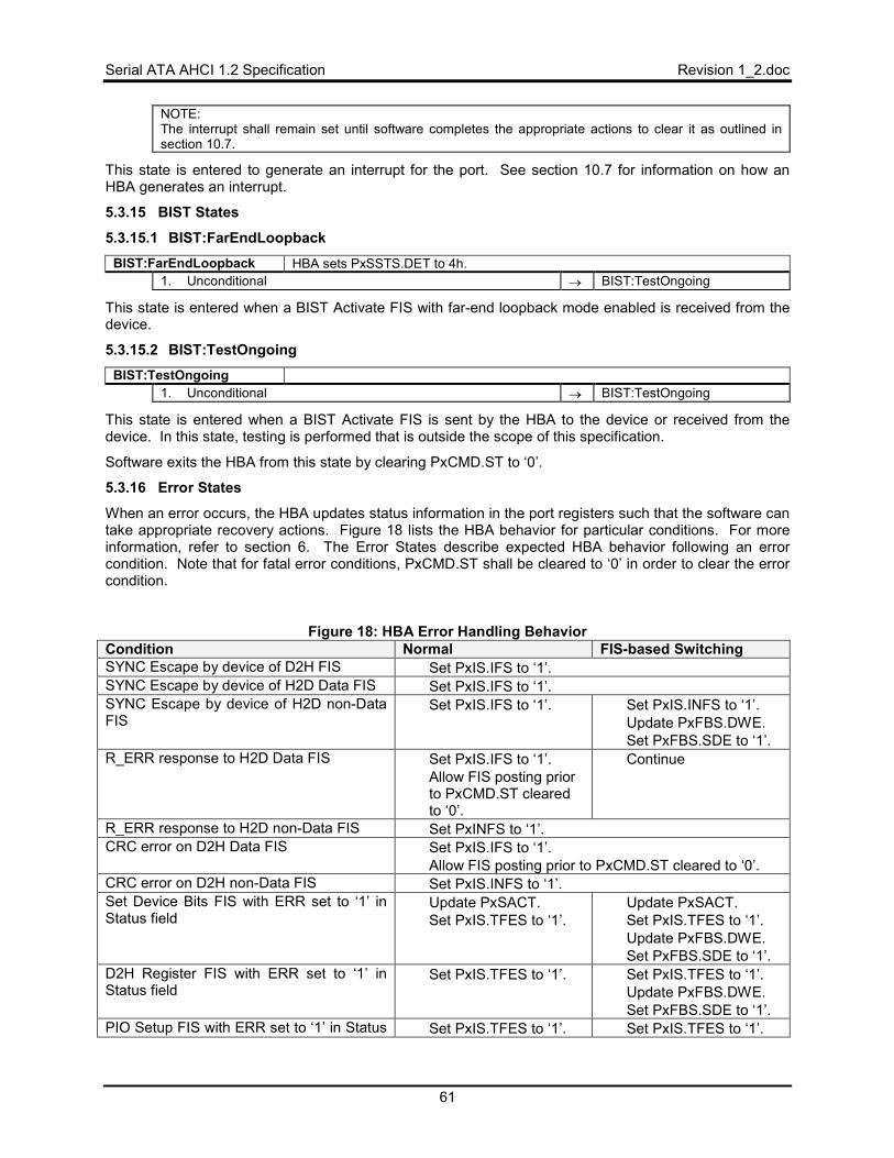
Serial ATA AHCI 1.2 Specification Revision 1_2.doc
61
NOTE: The interrupt shall remain set until software completes the appropriate actions to clear it as outlined in section 10.7.
This state is entered to generate an interrupt for the port. See section 10.7 for information on how an HBA generates an interrupt.
5.3.15 BIST States
5.3.15.1 BIST:FarEndLoopback BIST:FarEndLoopback HBA sets PxSSTS.DET to 4h.
1. Unconditional → BIST:TestOngoing
This state is entered when a BIST Activate FIS with far-end loopback mode enabled is received from the device.
5.3.15.2 BIST:TestOngoing BIST:TestOngoing
1. Unconditional → BIST:TestOngoing
This state is entered when a BIST Activate FIS is sent by the HBA to the device or received from the device. In this state, testing is performed that is outside the scope of this specification.
Software exits the HBA from this state by clearing PxCMD.ST to ‘0’.
5.3.16 Error States
When an error occurs, the HBA updates status information in the port registers such that the software can take appropriate recovery actions. Figure 18 lists the HBA behavior for particular conditions. For more information, refer to section 6. The Error States describe expected HBA behavior following an error condition. Note that for fatal error conditions, PxCMD.ST shall be cleared to ‘0’ in order to clear the error condition.
Figure 18: HBA Error Handling Behavior Condition Normal FIS-based Switching SYNC Escape by device of D2H FIS • Set PxIS.IFS to ‘1’. SYNC Escape by device of H2D Data FIS • Set PxIS.IFS to ‘1’. SYNC Escape by device of H2D non-Data FIS
• Set PxIS.IFS to ‘1’. • Set PxIS.INFS to ‘1’. • Update PxFBS.DWE. • Set PxFBS.SDE to ‘1’.
R_ERR response to H2D Data FIS • Set PxIS.IFS to ‘1’. • Allow FIS posting prior
to PxCMD.ST cleared to ‘0’.
• Continue
R_ERR response to H2D non-Data FIS • Set PxINFS to ‘1’. CRC error on D2H Data FIS • Set PxIS.IFS to ‘1’.
• Allow FIS posting prior to PxCMD.ST cleared to ‘0’. CRC error on D2H non-Data FIS • Set PxIS.INFS to ‘1’. Set Device Bits FIS with ERR set to ‘1’ in Status field
• Update PxSACT. • Set PxIS.TFES to ‘1’.
• Update PxSACT. • Set PxIS.TFES to ‘1’. • Update PxFBS.DWE. • Set PxFBS.SDE to ‘1’.
D2H Register FIS with ERR set to ‘1’ in Status field
• Set PxIS.TFES to ‘1’. • Set PxIS.TFES to ‘1’. • Update PxFBS.DWE. • Set PxFBS.SDE to ‘1’.
PIO Setup FIS with ERR set to ‘1’ in Status • Set PxIS.TFES to ‘1’. • Set PxIS.TFES to ‘1’.
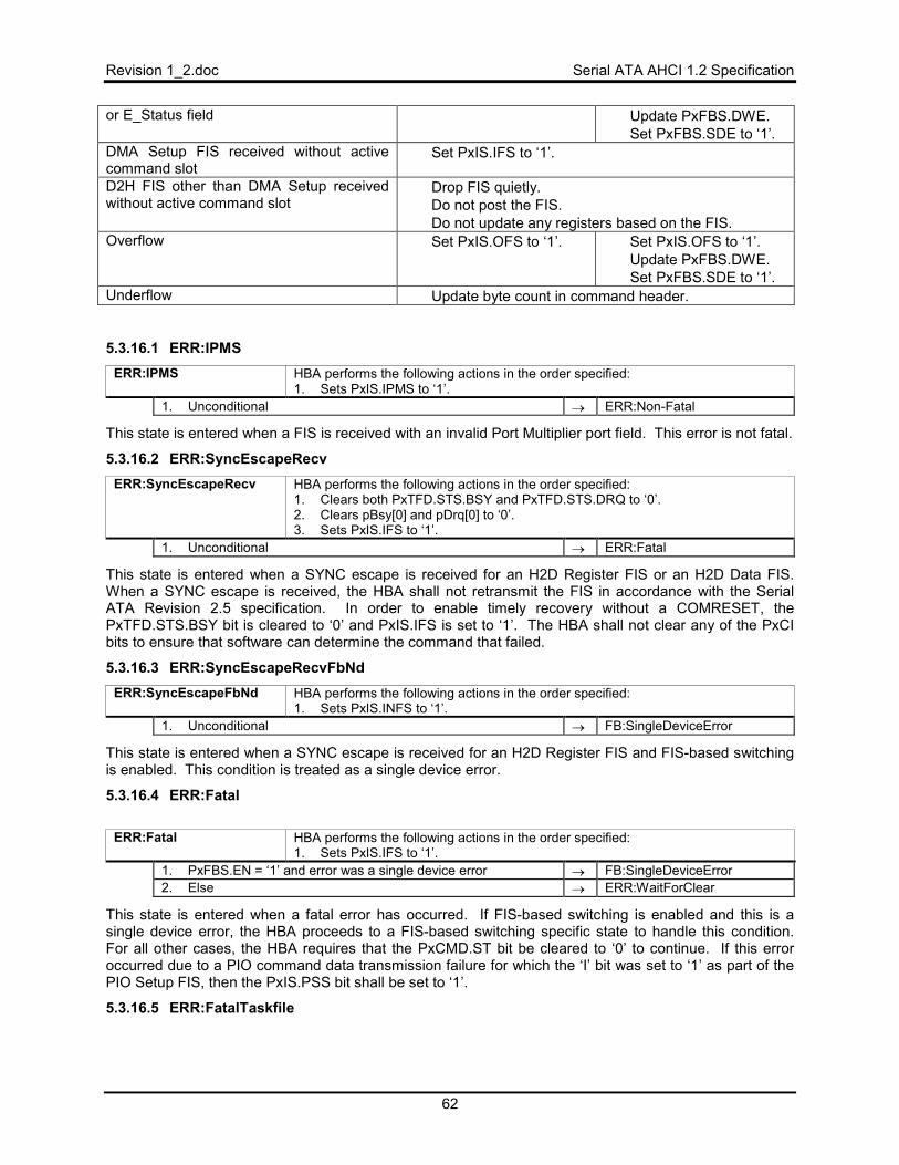
Revision 1_2.doc Serial ATA AHCI 1.2 Specification
62
or E_Status field • Update PxFBS.DWE. • Set PxFBS.SDE to ‘1’.
DMA Setup FIS received without active command slot
• Set PxIS.IFS to ‘1’.
D2H FIS other than DMA Setup received without active command slot
• Drop FIS quietly. • Do not post the FIS. • Do not update any registers based on the FIS.
Overflow • Set PxIS.OFS to ‘1’. • Set PxIS.OFS to ‘1’. • Update PxFBS.DWE. • Set PxFBS.SDE to ‘1’.
Underflow • Update byte count in command header.
5.3.16.1 ERR:IPMS ERR:IPMS HBA performs the following actions in the order specified:
1. Sets PxIS.IPMS to ‘1’. 1. Unconditional → ERR:Non-Fatal
This state is entered when a FIS is received with an invalid Port Multiplier port field. This error is not fatal.
5.3.16.2 ERR:SyncEscapeRecv ERR:SyncEscapeRecv HBA performs the following actions in the order specified:
1. Clears both PxTFD.STS.BSY and PxTFD.STS.DRQ to ‘0’. 2. Clears pBsy[0] and pDrq[0] to ‘0’. 3. Sets PxIS.IFS to ‘1’.
1. Unconditional → ERR:Fatal
This state is entered when a SYNC escape is received for an H2D Register FIS or an H2D Data FIS. When a SYNC escape is received, the HBA shall not retransmit the FIS in accordance with the Serial ATA Revision 2.5 specification. In order to enable timely recovery without a COMRESET, the PxTFD.STS.BSY bit is cleared to ‘0’ and PxIS.IFS is set to ‘1’. The HBA shall not clear any of the PxCI bits to ensure that software can determine the command that failed.
5.3.16.3 ERR:SyncEscapeRecvFbNd ERR:SyncEscapeFbNd HBA performs the following actions in the order specified:
1. Sets PxIS.INFS to ‘1’. 1. Unconditional → FB:SingleDeviceError
This state is entered when a SYNC escape is received for an H2D Register FIS and FIS-based switching is enabled. This condition is treated as a single device error.
5.3.16.4 ERR:Fatal
ERR:Fatal HBA performs the following actions in the order specified:
1. Sets PxIS.IFS to ‘1’. 1. PxFBS.EN = ‘1’ and error was a single device error → FB:SingleDeviceError 2. Else → ERR:WaitForClear
This state is entered when a fatal error has occurred. If FIS-based switching is enabled and this is a single device error, the HBA proceeds to a FIS-based switching specific state to handle this condition. For all other cases, the HBA requires that the PxCMD.ST bit be cleared to ‘0’ to continue. If this error occurred due to a PIO command data transmission failure for which the ‘I’ bit was set to ‘1’ as part of the PIO Setup FIS, then the PxIS.PSS bit shall be set to ‘1’.
5.3.16.5 ERR:FatalTaskfile
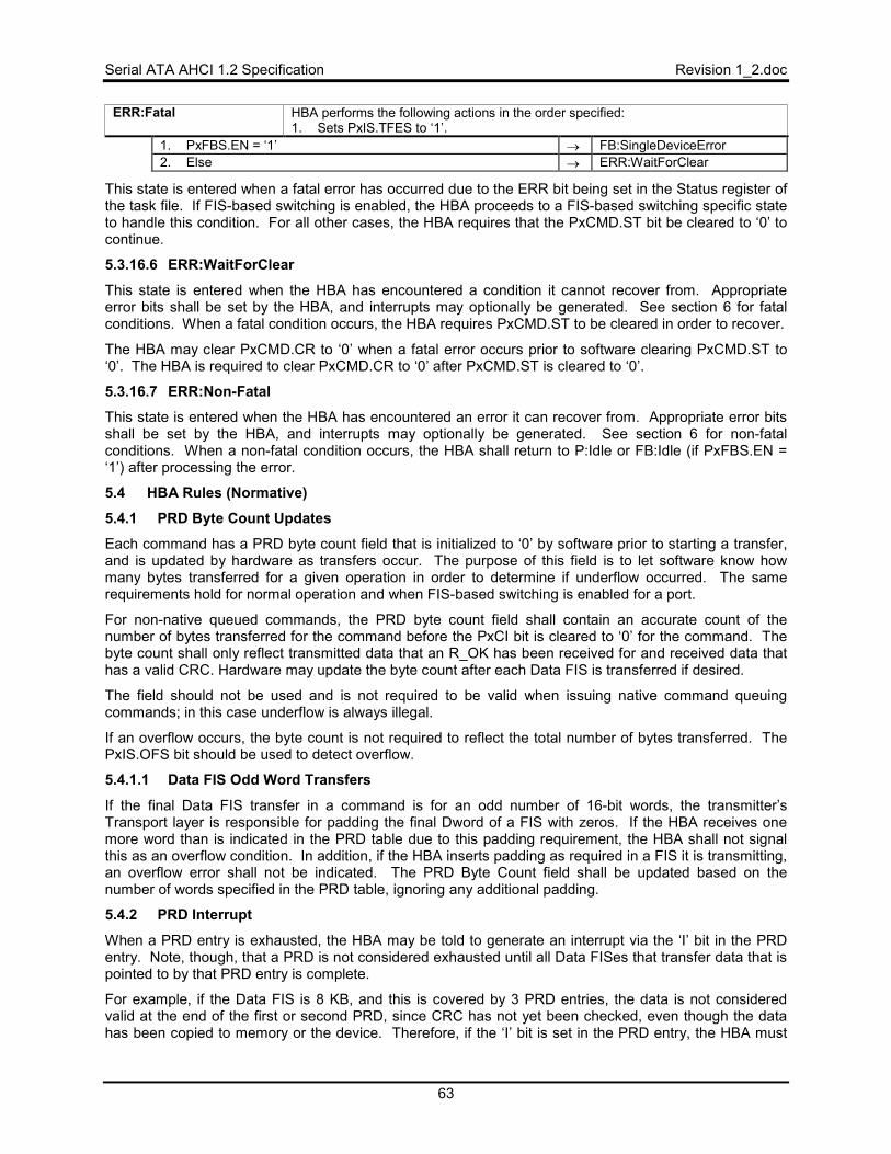
Serial ATA AHCI 1.2 Specification Revision 1_2.doc
63
ERR:Fatal HBA performs the following actions in the order specified: 1. Sets PxIS.TFES to ‘1’.
1. PxFBS.EN = ‘1’ → FB:SingleDeviceError 2. Else → ERR:WaitForClear
This state is entered when a fatal error has occurred due to the ERR bit being set in the Status register of the task file. If FIS-based switching is enabled, the HBA proceeds to a FIS-based switching specific state to handle this condition. For all other cases, the HBA requires that the PxCMD.ST bit be cleared to ‘0’ to continue.
5.3.16.6 ERR:WaitForClear
This state is entered when the HBA has encountered a condition it cannot recover from. Appropriate error bits shall be set by the HBA, and interrupts may optionally be generated. See section 6 for fatal conditions. When a fatal condition occurs, the HBA requires PxCMD.ST to be cleared in order to recover.
The HBA may clear PxCMD.CR to ‘0’ when a fatal error occurs prior to software clearing PxCMD.ST to ‘0’. The HBA is required to clear PxCMD.CR to ‘0’ after PxCMD.ST is cleared to ‘0’.
5.3.16.7 ERR:Non-Fatal
This state is entered when the HBA has encountered an error it can recover from. Appropriate error bits shall be set by the HBA, and interrupts may optionally be generated. See section 6 for non-fatal conditions. When a non-fatal condition occurs, the HBA shall return to P:Idle or FB:Idle (if PxFBS.EN = ‘1’) after processing the error.
5.4 HBA Rules (Normative)
5.4.1 PRD Byte Count Updates
Each command has a PRD byte count field that is initialized to ‘0’ by software prior to starting a transfer, and is updated by hardware as transfers occur. The purpose of this field is to let software know how many bytes transferred for a given operation in order to determine if underflow occurred. The same requirements hold for normal operation and when FIS-based switching is enabled for a port.
For non-native queued commands, the PRD byte count field shall contain an accurate count of the number of bytes transferred for the command before the PxCI bit is cleared to ‘0’ for the command. The byte count shall only reflect transmitted data that an R_OK has been received for and received data that has a valid CRC. Hardware may update the byte count after each Data FIS is transferred if desired.
The field should not be used and is not required to be valid when issuing native command queuing commands; in this case underflow is always illegal.
If an overflow occurs, the byte count is not required to reflect the total number of bytes transferred. The PxIS.OFS bit should be used to detect overflow.
5.4.1.1 Data FIS Odd Word Transfers
If the final Data FIS transfer in a command is for an odd number of 16-bit words, the transmitter’s Transport layer is responsible for padding the final Dword of a FIS with zeros. If the HBA receives one more word than is indicated in the PRD table due to this padding requirement, the HBA shall not signal this as an overflow condition. In addition, if the HBA inserts padding as required in a FIS it is transmitting, an overflow error shall not be indicated. The PRD Byte Count field shall be updated based on the number of words specified in the PRD table, ignoring any additional padding.
5.4.2 PRD Interrupt
When a PRD entry is exhausted, the HBA may be told to generate an interrupt via the ‘I’ bit in the PRD entry. Note, though, that a PRD is not considered exhausted until all Data FISes that transfer data that is pointed to by that PRD entry is complete.
For example, if the Data FIS is 8 KB, and this is covered by 3 PRD entries, the data is not considered valid at the end of the first or second PRD, since CRC has not yet been checked, even though the data has been copied to memory or the device. Therefore, if the ‘I’ bit is set in the PRD entry, the HBA must
Revision 1_2.doc Serial ATA AHCI 1.2 Specification
64
hold onto it internally and not set PxIS.DPS until the Data FIS is complete and CRC is correct. Once correct, PxIS.DPS can be set, and if PxIE.DPE and GHC.IE are set, the HBA shall generate an interrupt.
Conversely, if the PRD entry is 16 KB and two 8 KB Data FISes are used to transfer all of the data pointed to by the PRD entry, then the PRD interrupt associated with that PRD entry shall not be signaled until after the second Data FIS transfer has completed successfully.
The PRD Interrupt is an opportunistic interrupt. The PRD Interrupt should not be used to definitively indicate the end of a transfer. Two PRD interrupts could happen close in time together such that the second interrupt is missed when the first PRD interrupt is being cleared.
5.5 System Software Rules (Normative)
5.5.1 Basic Steps when Building a Command
When software builds a command for the HBA to execute, it first finds an empty command slot by reading the PxCI and PxSACT registers for the port. An empty command slot has its respective bit cleared to ‘0’ in both the PxCI and PxSACT registers. After a free slot (slot pFreeSlot), is found:
1. Software builds a command FIS in system memory at location PxCLB[CH(pFreeSlot)]:CFIS with the command type.
2. If it is an ATAPI command, the ACMD field shall be filled in with the ATAPI command 3. Software builds a command header at PxCLB[CH(pFreeSlot)] with:
a. PRDTL containing the number of entries in the PRD table b. CFL set to the length of the command in the CFIS area c. A bit set if it is an ATAPI command d. W (Write) bit set if data is going to the device e. P (Prefetch) bit optionally set (see rules in section 5.5.2) f. If a Port Multiplier is attached, the PMP field set to the correct Port Multiplier port.
4. If it is a queued command, software shall first set PxSACT.DS(pFreeSlot). Software should only write new bits to set to ‘1’; the previous register content of PxSACT should not be re-written in the register write.
5. Software shall set PxCI.CI(pFreeSlot) to indicate to the HBA that a command is active. Software should only write new bits to set to ‘1’; the previous register content of PxCI should not be re-written in the register write.
5.5.2 Setting CH(pFreeSlot).P
When software builds commands for the HBA to execute, it may optionally set CH(pFreeSlot).P to enable prefetching of PRDs and data. The HBA is not required to prefetch, but may use this bit to do so. To avoid potential problems where the HBA may prefetch items it cannot use, software must obey the following rules:
• Software shall not set CH(pFreeSlot).P when building queued ATA commands. The Serial ATA device may run the commands in a different order than what is sent.
• Software shall not set CH(pFreeSlot).P when building commands to several devices behind a Port Multiplier when FIS based switching is enabled. FISes may be received from a Port Multiplier for a different device than what was just sent by the HBA.
If software does not obey these rules, indeterminate HBA behavior may result.
5.5.3 Processing Completed Commands
Software processes the interrupt generated by the device for command completion. In the interrupt service routine, software checks IS.IPS to determine which ports have an interrupt pending.
For each port that has an interrupt pending: 1. Software determines the cause of the interrupt by reading the PxIS register. It is
possible for multiple bits to be set 2. Software clears appropriate bits in the PxIS register corresponding to the cause of
the interrupt.
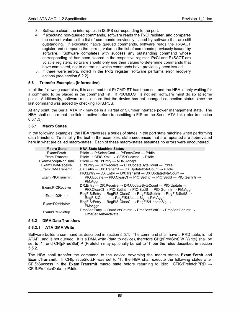
Serial ATA AHCI 1.2 Specification Revision 1_2.doc
65
3. Software clears the interrupt bit in IS.IPS corresponding to the port. 4. If executing non-queued commands, software reads the PxCI register, and compares
the current value to the list of commands previously issued by software that are still outstanding. If executing native queued commands, software reads the PxSACT register and compares the current value to the list of commands previously issued by software. Software completes with success any outstanding command whose corresponding bit has been cleared in the respective register. PxCI and PxSACT are volatile registers; software should only use their values to determine commands that have completed, not to determine which commands have previously been issued.
5. If there were errors, noted in the PxIS register, software performs error recovery actions (see section 6.2.2).
5.6 Transfer Examples (Informative)
In all the following examples, it is assumed that PxCMD.ST has been set, and the HBA is only waiting for a command to be placed in the command list. If PxCMD.ST is not set, software must do so at some point. Additionally, software must ensure that the device has not changed connection status since the last command was added by checking PxIS.PCS.
At any point, the Serial ATA link may be in a Partial or Slumber interface power management state. The HBA shall ensure that the link is active before transmitting a FIS on the Serial ATA link (refer to section 8.3.1.3).
5.6.1 Macro States
In the following examples, the HBA traverses a series of states in the port state machine when performing data transfers. To simplify the text in the examples, state sequences that are repeated are abbreviated here in what are called macro-states. Each of these macro-states assumes no errors were encountered.
Macro State HBA State Machine States Exam:Fetch P:Idle → P:SelectCmd → P:FetchCmd → P:Idle
Exam:Transmit P:Idle → CFIS:Xmit → CFIS:Success → P:Idle Exam:AcceptNonData P:Idle → NDR:Entry → NDR:Accept
Exam:DMAReceive DR:Entry → DR:Receive → DR:UpdateByteCount → P:Idle Exam:DMATransmit DX:Entry → DX:Transmit → DX:UpdateByteCount → P:Idle
Exam:PIOTransmit PIO:Entry → DX:Entry → DX:Transmit → DX:UpdateByteCount →
PIO:Update → PIO:ClearCI → PIO:SetIntr → PIO:SetIS → PIO:GenIntr →PM:Aggr
Exam:PIOReceive DR:Entry → DR:Receive → DR:UpdateByteCount → PIO:Update →PIO:ClearCI → PIO:SetIntr → PIO:SetIS → PIO:GenIntr → PM:Aggr
Exam:D2HIntr RegFIS:Entry → RegFIS:ClearCI → RegFIS:SetIntr → RegFIS:SetIS →RegFIS:GenIntr → RegFIS:UpdateSig → PM:Aggr
Exam:D2HNoIntr RegFIS:Entry → RegFIS:ClearCI → RegFIS:UpdateSig →PM:Aggr
Exam:DMASetup DmaSet:Entry → DmaSet:SetIntr → DmaSet:SetIS → DmaSet:GenIntr →DmaSet:AutoActivate
5.6.2 DMA Data Transfers
5.6.2.1 ATA DMA Write
Software builds a command as described in section 5.5.1. The command shall have a PRD table, is not ATAPI, and is not queued. It is a DMA write (data to device), therefore CH(pFreeSlot).W (Write) shall be set to ‘1’, and CH(pFreeSlot).P (Prefetch) may optionally be set to ‘1’ per the rules described in section 5.5.2.
The HBA shall transfer the command to the device traversing the macro states Exam:Fetch and Exam:Transmit. If CH(pIssueSlot).P was set to ‘1’, the HBA shall execute the following states after CFIS:Success in the Exam:Transmit macro state before returning to idle: CFIS:PrefetchPRD →CFIS:PrefetchData → P:Idle.
Revision 1_2.doc Serial ATA AHCI 1.2 Specification
66
As this was a DMA write command, the response from the device shall be a DMA Activate FIS. When this arrives, the HBA shall accept the FIS by traversing the Exam:AcceptNonData macro state, and shall send a Data FIS by traversing the Exam:DMATransmit macro state.
If the Data FIS did not satisfy the transfer count, another DMA Activate FIS shall be sent from the device, and the HBA shall traverse the Exam:AcceptNonData and Exam:DMATransmit macro states again to send another Data FIS. This process continues until the transfer count is satisfied. When the Data FIS that completes the transfer count finishes, the next FIS from the device shall be a D2H Register FIS.
The HBA shall accept this FIS by traversing the Exam:AcceptNonData macro state. If the D2H Register FIS had the ‘I’ bit set to ‘1’, the HBA shall traverse the Exam:D2HIntr macro state. If the ‘I’ bit was not set to ‘1’, the HBA shall traverse the Exam:D2HNoIntr state.
If this was the last command, and the HBA was enabled for aggressive power management, the HBA shall first request the link to be placed in either the Partial or Slumber interface power management state after the PM:Aggr state.
5.6.2.2 ATAPI Packet DMA Write
Software builds a command as described in section 5.5.1. The command shall have a PRD table, is ATAPI, and is not queued. It is a DMA write (data to device), therefore CH(pFreeSlot).W (Write) shall be set to ‘1’, and CH(pFreeSlot).P (Prefetch) may optionally be set per the rules described in section 5.5.2.
The HBA shall transfer the command to the device traversing the macro states Exam:Fetch and Exam:Transmit. If CH(pIssueSlot).P was set, the HBA shall execute the following states after CFIS:Success in the Exam:Transmit macro state before returning to idle: CFIS:PrefetchACMD →CFIS:PrefetchPRD → CFIS:PrefetchData → P:Idle.
Since this was an ATAPI command, the next FIS from the device shall be a PIO Setup FIS. The HBA traverses the Exam:AcceptNonData macro state to accept this FIS, and then traverses the following states to transfer the ACMD field to the device: PIO:Entry → ATAPI:Entry → PIO:Update → P:Idle
As this command results in a DMA write, the response from the device shall be a DMA Activate FIS. When this arrives, the HBA shall accept the FIS by traversing the Exam:AcceptNonData macro state, and shall send a Data FIS by traversing the Exam:DMATransmit macro state.
If the Data FIS did not satisfy the transfer count, another DMA Activate FIS shall be sent from the device, and the HBA shall traverse the Exam:AcceptNonData and Exam:DMATransmit macro states again to send another Data FIS. This process continues until the transfer count is satisfied. When the Data FIS that completes the transfer count finishes, the next FIS from the device shall be a D2H Register FIS.
The HBA shall accept this FIS by traversing the Exam:AcceptNonData macro state. If the D2H Register FIS had the ‘I’ bit set to ‘1’, the HBA shall traverse the Exam:D2HIntr macro state. If the ‘I’ bit was not set to ‘1’, the HBA shall traverse the Exam:D2HNoIntr state.
If this was the last command, and the HBA was enabled for aggressive power management, the HBA shall first request the link to be placed in either the Partial or Slumber interface power management state after the PM:Aggr state.
5.6.2.3 ATA DMA Read
Software builds a command as described in section 5.5.1. The command shall have a PRD table, is not ATAPI, and is not queued. It is a DMA read (data to memory), therefore CH(pFreeSlot).W (Write) shall be cleared to ‘0’, and CH(pFreeSlot).P (Prefetch) may optionally be set to ‘1’ per the rules described in section 5.5.2.
The HBA shall transfer the command to the device traversing the macro states Exam:Fetch and Exam:Transmit. If CH(pIssueSlot).P was set to ‘1’, the HBA shall execute the following states after CFIS:Success in the Exam:Transmit macro state before returning to idle: CFIS:PrefetchPRD → P:Idle
As this was a DMA read command, the response from the device shall be a Data FIS. When this arrives, the HBA shall traverse the Exam:DMAReceive macro state.

Serial ATA AHCI 1.2 Specification Revision 1_2.doc
67
If the Data FIS did not satisfy the transfer count, another Data FIS shall be sent from the device, and the HBA shall traverse the Exam:DMAReceive macro states again. This process continues until the transfer count is satisfied. When the Data FIS that completes the transfer count finishes, the next FIS from the device shall be a D2H Register FIS.
The HBA shall accept this FIS by traversing the Exam:AcceptNonData macro state. If the D2H Register FIS had the ‘I’ bit set to ‘1’, the HBA shall traverse the Exam:D2HIntr macro state. If the ‘I’ bit was not set to ‘1’, the HBA shall traverse the Exam:D2HNoIntr state.
If this was the last command, and the HBA was enabled for aggressive power management, the HBA shall first request the link to be placed in either the Partial or Slumber interface power management state after the PM:Aggr state.
5.6.2.4 ATAPI Packet DMA Read
Software builds a command as described in section 5.5.1. The command shall have a PRD table, is ATAPI, and is not queued. It is a DMA read (data to memory), therefore CH(pFreeSlot).W (Write) shall be cleared to ‘0’, and CH(pFreeSlot).P (Prefetch) may optionally be set to ‘1’ per the rules described in section 5.5.2.
The HBA shall transfer the command to the device traversing the macro states Exam:Fetch and Exam:Transmit. If CH(pIssueSlot).P was set to ‘1’, the HBA shall execute the following states after CFIS:Success in the Exam:Transmit macro state before returning to idle: CFIS:PrefetchACMD →CFIS:PrefetchPRD → P:Idle.
Since this was an ATAPI command, the next FIS from the device shall be a PIO Setup FIS. The HBA traverses the Exam:AcceptNonData macro state to accept this FIS, and then traverses the following states to transfer the ACMD field to the device: PIO:Entry → ATAPI:Entry → PIO:Update → P:Idle.
As this command results in a DMA read, the response from the device shall be a Data FIS. When this arrives, the HBA shall traverse the Exam:DMAReceive macro state.
If the Data FIS did not satisfy the transfer count, another Data FIS shall be sent from the device, and the HBA shall traverse the Exam:DMAReceive macro states again. This process continues until the transfer count is satisfied. When the Data FIS that completes the transfer count finishes, the next FIS from the device shall be a D2H Register FIS.
The HBA shall accept this FIS by traversing the Exam:AcceptNonData macro state. If the D2H Register FIS had the ‘I’ bit set to ‘1’, the HBA shall traverse the Exam:D2HIntr macro state. If the ‘I’ bit was not set to ‘1’, the HBA shall traverse the Exam:D2HNoIntr state.
If this was the last command, and the HBA was enabled for aggressive power management, the HBA shall first request the link to be placed in either the Partial or Slumber interface power management state after the PM:Aggr state.
5.6.3 PIO Data Transfers
The following sections describe data transfers to and from a device using PIO as the command protocol type. PIO data transfers are highly discouraged because of the inadequate error handling coverage for PIO read commands. Some AHCI implementations may choose to only implement support to transfer a single DRQ block in a PIO command. If CAP.PMD is cleared to ‘0’, then the HBA only supports single DRQ block PIO transfers and software must ensure commands are not issued to the device that are for more than one DRQ block of data. Note that when CAP.PMD is cleared to ‘0’, drive functionality is reduced. It is recommended that implementations support multiple DRQ block PIO operation.
Software should ensure that for ATA devices the SET MULTIPLE MODE count is set to a value that is less than or equal to 16. Software should ensure that for ATAPI devices, the maximum byte count is set to 8KB for the PACKET command. This is required by Serial ATA to ensure that Data FISes are no larger than 8KB.
From the HBA’s point of view, PIO data transfers look like a DMA transfer. A command table is set up, and the data is bus mastered from or to system memory by the HBA.
Revision 1_2.doc Serial ATA AHCI 1.2 Specification
68
5.6.3.1 ATA PIO Write
Software builds a command as described in section 5.5.1. The command shall have a PRD table, is not ATAPI, and is not queued. It is a PIO Write (data to device), therefore CH(pFreeSlot).W (Write) shall be set to ‘1’, and CH(pFreeSlot).P (Prefetch) may optionally be set to ‘1’ per the rules described in section 5.5.2.
The HBA shall transfer the command to the device traversing the macro states Exam:Fetch and Exam:Transmit. If CH(pIssueSlot).P was set, the HBA shall execute the following states after CFIS:Success in the Exam:Transmit macro state before returning to idle: CFIS:PrefetchPRD →CFIS:PrefetchData → P:Idle.
As this was a PIO write command, the response from the device shall be a PIO Setup FIS. When this arrives, the HBA shall accept the FIS by traversing the Exam:AcceptNonData macro state. It shall then traverse the Exam:PIOTransmit macro state to send a Data FIS.
Since this was PIO write command, the device shall next send a D2H Register FIS. The HBA shall accept this FIS by traversing the Exam:AcceptNonData macro state. If the D2H Register FIS had the ‘I’ bit set to ‘1’, the HBA shall traverse the Exam:D2HIntr macro state. If the ‘I’ bit was not set to ‘1’, the HBA shall traverse the Exam:D2HNoIntr state.
If this was the last command, and the HBA was enabled for aggressive power management, the HBA shall first request the link to be placed in either the Partial or Slumber interface power management state after the PM:Aggr state.
5.6.3.2 ATAPI Packet PIO Write
Software builds a command as described in section 5.5.1. The command shall have a PRD table, is ATAPI, and is not queued. It is a PIO Write (data to device), therefore CH(pFreeSlot).W (Write) shall be set to ‘1, and CH(pFreeSlot).P (Prefetch) may optionally be set to ‘1’ per the rules described in section 5.5.2.
The HBA shall transfer the command to the device traversing the macro states Exam:Fetch and Exam:Transmit. If CH(pIssueSlot).P was set to ‘1’, the HBA shall execute the following states after CFIS:Success in the Exam:Transmit macro state before returning to idle: CFIS:PrefetchACMD →CFIS:PrefetchPRD → CFIS:PrefetchData → P:Idle.
Since this was an ATAPI command, the next FIS from the device shall be a PIO Setup FIS. The HBA traverses the Exam:AcceptNonData macro state to accept this FIS, and then traverses the following states to transfer the ACMD field to the device: PIO:Entry → ATAPI:Entry → PIO:Update → P:Idle
As this was a PIO Write command, the response from the device shall be a PIO Setup FIS. When this arrives, the HBA shall accept the FIS by traversing the Exam:AcceptNonData macro state. It shall then traverse the Exam:PIOTransmit macro state to send a Data FIS to the device.
Since this was an PIO ATAPI write command, the device shall send a D2H Register FIS. The HBA shall accept this FIS by traversing the Exam:AcceptNonData macro state. If the D2H Register FIS had the ‘I’ bit set to ‘1’, the HBA shall traverse the Exam:D2HIntr macro state. If the ‘I’ bit was not set to ‘1’, the HBA shall traverse the Exam:D2HNoIntr state.
If this was the last command, and the HBA was enabled for aggressive power management, the HBA shall first request the link to be placed in either the Partial or Slumber interface power management state after the PM:Aggr state.
5.6.3.3 ATA PIO Read
Software builds a command as described in section 5.5.1. The command shall have a PRD table, is not ATAPI, and is not queued. It is a PIO Read (data to memory), therefore CH(pFreeSlot).W (Write) shall be cleared to ‘0’, and CH(pFreeSlot).P (Prefetch) may optionally be set to ‘1’ per the rules described in section 5.5.2.
Serial ATA AHCI 1.2 Specification Revision 1_2.doc
69
The HBA shall transfer the command to the device traversing the macro states Exam:Fetch and Exam:Transmit. If CH(pIssueSlot).P was set to ‘1’, the HBA shall execute the following states after CFIS:Success in the Exam:Transmit macro state before returning to idle: CFIS:PrefetchPRD → P:Idle
As this was a PIO read command, the response from the device shall be a PIO Setup FIS. When this arrives, the HBA shall accept the FIS by traversing the Exam:AcceptNonData macro state. It shall then traverse the states PIO:Entry → P:Idle, and await a Data FIS from the device.
When the Data FIS arrives, the HBA traverses the Exam:PIOReceive macro state.
If this was the last command, and the HBA was enabled for aggressive power management, the HBA shall first request the link to be placed in either the Partial or Slumber interface power management state after the PM:Aggr state.
5.6.3.4 ATAPI Packet PIO Read
Software builds a command as described in section 5.5.1. The command shall have a PRD table, is ATAPI, and is not queued. It is a PIO Read (data to memory), therefore CH(pFreeSlot).W (Write) shall be cleared to ‘0’, and CH(pFreeSlot).P (Prefetch) may optionally be set to ‘1’ per the rules described in section 5.5.2.
The HBA shall transfer the command to the device traversing the macro states Exam:Fetch and Exam:Transmit. If CH(IssueSlot).P was set to ‘1’, the HBA shall execute the following states after CFIS:Success in the Exam:Transmit macro state before returning to idle: CFIS:PrefetchACMD →CFIS:PrefetchPRD → P:Idle.
Since this was an ATAPI command, the next FIS from the device shall be a PIO Setup FIS. The HBA traverses the Exam:AcceptNonData macro state to accept this FIS, and then traverses the following states to transfer the ACMD field to the device: PIO:Entry → ATAPI:Entry → PIO:Update → P:Idle
As this was a PIO read command, the response from the device shall be a PIO Setup FIS. When this arrives, the HBA shall accept the FIS by traversing the Exam:AcceptNonData macro state. It shall then traverse the states PIO:Entry → H:Idle, and await a Data FIS from the device.
When the Data FIS arrives, the HBA traverses the Exam:PIOReceive macro state.
Since this was an ATAPI command, the device shall next send a D2H Register FIS. The HBA shall accept this FIS by traversing the Exam:AcceptNonData macro state. If the D2H Register FIS had the ‘I’ bit set, the HBA shall traverse the Exam:D2HIntr macro state. If the ‘I’ bit was not set, the HBA shall traverse the Exam:D2HNoIntr state.
If this was the last command, and the HBA was enabled for aggressive power management, the HBA shall first request the link to be placed in either the Partial or Slumber interface power management state after the PM:Aggr state.
5.6.4 Native Queued Command Transfers
5.6.4.1 Introduction
The ATA/ATAPI-7 queued feature set is not supported by AHCI (including the READ QUEUED (EXT), WRITE QUEUED (EXT), and SERVICE commands). Queued operations are supported in AHCI using the READ FPDMA QUEUED and WRITE FPDMA QUEUED commands when the HBA and device support native command queuing.
To allow a simple mechanism for the HBA to map command list slots to queue entries, software must match the tag number it uses to the slot it is placing the command in. For example, if a queued command is placed in slot 5, the tag for that command must be 5.
System software must determine the maximum tag allowed by the device and the HBA and it must use the lower bound of the two. For example, if the HBA has 8 entries in its command list, and the SATA device only has 4, only tags 0 – 3 in the device may be used, and only command list entries 0 – 3 may be used in the HBA.
Revision 1_2.doc Serial ATA AHCI 1.2 Specification
70
Data transfers are activated with the flow described below via the DMA Setup FIS, and command completion is performed via the Set Device Bits FIS.
5.6.4.2 Example
In the following example, the following occurs: • System software places 4 commands in system memory:
o Slot 0 contains a READ FPDMA QUEUED o Slot 2 contains a WRITE FPDMA QUEUED o Slot 5 contains a READ FPDMA QUEUED o Slot 8 contains a WRITE FPDMA QUEUED
• The HBA fetches the first 3 commands, transfers them to the device, and receives a successful completion.
• Before the HBA can send the 4th command to the device, the device sends a DMA Setup FIS to transfer data for the command in slot 2.
• A data transfer occurs to slot 2. • The HBA transfers slot 8 to the device. • A data transfer occurs to slot 5. • The device sends an SDB FIS to clear slots 2 and 5. • A data transfer occurs to slot 8. • The device sends an SDB FIS to clear slot 8. • A data transfer occurs to slot 0. • The device sends an SDB FIS to clear slot 0.
Other items to note in this data flow: • In both WRITE FPDMA QUEUED commands, the auto-activate bit is not set in the FIS. • Every SDB FIS received has the ‘I’ bit set to ‘1’.
Following is a text description for the flow.
System Software Places 4 Commands in System Memory
Software builds a command into slot 0 as described in section 5.5.1. The command shall have a PRD table, is not ATAPI, and has a READ FPDMA QUEUED opcode. CH(0).W (Write) shall be cleared to ‘0’, and CH(0).P (Prefetch) shall be cleared to ‘0’.
Software builds a command into slot 2 as described in section 5.5.1. The command shall have a PRD table, is not ATAPI, and has a WRITE FPDMA QUEUED opcode. CH(2).W (Write) shall be set to ‘1’ and CH(2).P (Prefetch) shall be cleared to ‘0’.
Software builds a command into slot 5 as described in section 5.5.1. The command shall have a PRD table, is not ATAPI, and has a READ FPDMA QUEUED opcode. Both CH(5).W (Write) and CH(5).P (Prefetch) shall be cleared to ‘0’.
Software builds a command into slot 8 as described in section 5.5.1. The command shall have a PRD table, is not ATAPI, and has a WRITE FPDMA QUEUED opcode. CH(8).W (Write) shall be set to ‘1’, and CH(8).P (Prefetch) shall be cleared to ‘0’.
At this point, the PxCI and PxSACT register values are “00000125h” (bits 0, 2, 5, and 8 are set).
The HBA transmits the First 3 Commands to the Device
The HBA shall transfer the command from slot 0 to the device traversing the macro states Exam:Fetch and Exam:Transmit. As this was a native queued command, the next FIS from the device shall be a D2H Register FIS with the ‘I’ bit cleared to ‘0’.
The HBA shall accept this FIS by traversing the Exam:AcceptNonData macro state. The ‘I’ bit was cleared to ‘0’ so the HBA shall traverse the Exam:D2HNoIntr state. PxCI is now equal to “00000124h”.
Serial ATA AHCI 1.2 Specification Revision 1_2.doc
71
The HBA shall transfer the command from slot 2 to the device traversing the macro states Exam:Fetch and Exam:Transmit. As this was a native queued command, the next FIS from the device shall be a D2H Register FIS with the ‘I’ bit cleared to ‘0’.
The HBA shall accept this FIS by traversing the Exam:AcceptNonData macro state. The ‘I’ bit was cleared to ‘0’ so the HBA shall traverse the Exam:D2HNoIntr state. PxCI is now equal to “00000120h”.
The HBA shall transfer the command from slot 5 to the device traversing the macro states Exam:Fetch and Exam:Transmit. As this was a native queued command, the next FIS from the device shall be a D2H Register FIS with the ‘I’ bit cleared to ‘0’.
The HBA shall accept this FIS by traversing the Exam:AcceptNonData macro state. The ‘I’ bit was cleared to ‘0’ so the HBA shall traverse the Exam:D2HNoIntr state. PxCI is now equal to “00000100h”.
DMA Setup FIS Arrives for slot 2
The HBA is now in an idle state, but before it can fetch a new command, a short FIS arrives from the device. This FIS is the DMA Setup FIS. The HBA shall accept this FIS by traversing the Exam:AcceptNonData macro state, and then traverses the Exam:DMASetup macro state to process the DMA Setup FIS. The tag indicated in the FIS was for slot 2.
Data Transfer for slot 2
As this was a DMA write command, and the auto-activate bit was not set in the FIS, the next FIS from the device shall be a DMA Activate FIS. When this arrives, the HBA shall accept the FIS by traversing the Exam:AcceptNonData macro state, and shall send a Data FIS by traversing the Exam:DMATransmit macro state.
If the Data FIS did not satisfy the transfer count, another DMA Activate FIS shall be sent from the device, and the HBA shall traverse the Exam:AcceptNonData and Exam:DMATransmit macro states again to send another Data FIS. This process continues until the transfer count is satisfied. The state machine is now in P:Idle
HBA transfers slot 8 to the device
Since PxCI is not all 0h, and no other FIS is coming in from the device, the HBA shall transfer the command from slot 8 to the device traversing the macro states Exam:Fetch and Exam:Transmit.As this was a native queued command, the next FIS from the device shall be a D2H Register FIS with the ‘I’ bit cleared to ‘0’.
The HBA shall accept this FIS by traversing the Exam:AcceptNonData macro state. The ‘I’ bit was cleared to ‘0’ so the HBA shall traverse the Exam:D2HNoIntr state. PxCI is now equal to “00000000h”.
Data transfer to slot 5
A short FIS arrives from the device of type DMA Setup FIS. The HBA shall accept this FIS by traversing the Exam:AcceptNonData macro state, and then traverses the Exam:DMASetup macro state to process the DMA Setup FIS. The tag indicated in the FIS was for slot 5.
As this was a DMA read command, the next FIS from the device shall be a Data FIS. When this arrives, the HBA shall traverse the Exam:DMAReceive macro state.
If the Data FIS did not satisfy the transfer count, another Data FIS shall be sent from the device, and the HBA shall traverse the Exam:DMAReceive macro states again. This process continues until the transfer count is satisfied. The HBA state machine is now in P:Idle.
Device sends SDB FIS to clear slots 2 and 5
At this point, the device sends an SDB FIS to indicate slots 2 and 5 are complete. The HBA shall accept this FIS by traversing the Exam:AcceptNonData macro state, and then traverses the SDB:Entry, and, since the received FIS had the ‘I’ bit set, the SDB:SetIntr → SDB:SetIS →
Revision 1_2.doc Serial ATA AHCI 1.2 Specification
72
SDB:GenIntr states, and returns to PM:Aggr → P:Idle. The PxSACT register is now equal to “00000101h”.
Data transfer occurs to slot 8
A short FIS arrives from the device of type DMA Setup FIS. The HBA shall accept this FIS by traversing the Exam:AcceptNonData macro state, and then traverses the Exam:DMASetup macro state to process the DMA Setup FIS. The tag indicated in the FIS was for slot 8.
As this was a DMA write command, and the auto-activate bit was not set in the FIS, the next FIS from the device shall be a DMA Activate FIS. When this arrives, the HBA shall accept the FIS by traversing the Exam:AcceptNonData macro state, and shall send a Data FIS by traversing the Exam:DMATransmit macro state.
If the Data FIS did not satisfy the transfer count, another DMA Activate FIS shall be sent from the device, and the HBA shall traverse the Exam:AcceptNonData and Exam:DMATransmit macro states again to send another Data FIS. This process continues until the transfer count is satisfied. The HBA state machine is now in P:Idle.
Device sends SDB FIS to clear slot 8
At this point, the device sends an SDB FIS to indicate slot 8 is complete. The HBA shall accept this FIS by traversing the Exam:AcceptNonData macro state, and then traverses the SDB:Entry, and, since the received FIS had the ‘I’ bit set, the SDB:SetIntr → SDB:SetIS → SDB:GenIntr states, and returns to PM:Aggr → P:Idle. The PxSACT register is now equal to “00000001h”.
Data transfer occurs to slot 0
A short FIS arrives from the device of type DMA Setup FIS. The HBA shall accept this FIS by traversing the Exam:AcceptNonData macro state, and then traverses the Exam:DMASetup macro state to process the DMA Setup FIS. The tag indicated in the FIS was for slot 2.
As this was a DMA read command, the next FIS from the device shall be a Data FIS. When this arrives, the HBA shall traverse the Exam:DMAReceive macro state.
If the Data FIS did not satisfy the transfer count, another Data FIS shall be sent from the device, and the HBA shall traverse the Exam:DMAReceive macro states again. This process continues until the transfer count is satisfied. The HBA state machine is now in P:Idle.
Device sends SDB FIS to clear slot 0
At this point, the device sends an SDB FIS to indicate slot 0 is complete. The HBA shall accept this FIS by traversing the Exam:AcceptNonData macro state, and then traverses the SDB:Entry, and, since the received FIS had its I bit set, the SDB:SetIntr → SDB:SetIS → SDB:GenIntr states, and returns to PM:Aggr. The PxSACT register is now equal to “00000000h”.
Since the PxCI and PxSACT registers are now both equal to “00000000h”, if the HBA was enabled for aggressive power management, the HBA shall first request the link to be placed in either the Partial or Slumber power management after the PM:Aggr state.
5.6.5 FIS-based Switching Command Transfers
5.6.5.1 Introduction
When using Port Multipliers in a FIS-based switching fashion, the HBA has additional responsibilities to ensure high performance data transfers amongst multiple devices attached behind a single port.
5.6.5.2 Example
In the following example, the following occurs: • System software places four commands in system memory for two separate devices:
o Slot 0 contains a READ FPDMA QUEUED for PM port of 3 and NCQ tag of 0 o Slot 2 contains a WRITE DMA EXT for device with PM port of 7
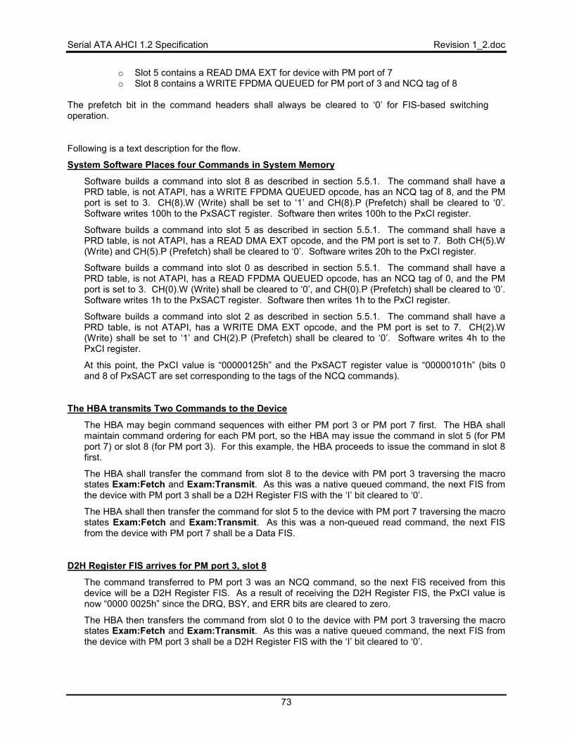
Serial ATA AHCI 1.2 Specification Revision 1_2.doc
73
o Slot 5 contains a READ DMA EXT for device with PM port of 7 o Slot 8 contains a WRITE FPDMA QUEUED for PM port of 3 and NCQ tag of 8
The prefetch bit in the command headers shall always be cleared to ‘0’ for FIS-based switching operation.
Following is a text description for the flow.
System Software Places four Commands in System Memory
Software builds a command into slot 8 as described in section 5.5.1. The command shall have a PRD table, is not ATAPI, has a WRITE FPDMA QUEUED opcode, has an NCQ tag of 8, and the PM port is set to 3. CH(8).W (Write) shall be set to ‘1’ and CH(8).P (Prefetch) shall be cleared to ‘0’. Software writes 100h to the PxSACT register. Software then writes 100h to the PxCI register.
Software builds a command into slot 5 as described in section 5.5.1. The command shall have a PRD table, is not ATAPI, has a READ DMA EXT opcode, and the PM port is set to 7. Both CH(5).W (Write) and CH(5).P (Prefetch) shall be cleared to ‘0’. Software writes 20h to the PxCI register.
Software builds a command into slot 0 as described in section 5.5.1. The command shall have a PRD table, is not ATAPI, has a READ FPDMA QUEUED opcode, has an NCQ tag of 0, and the PM port is set to 3. CH(0).W (Write) shall be cleared to ‘0’, and CH(0).P (Prefetch) shall be cleared to ‘0’. Software writes 1h to the PxSACT register. Software then writes 1h to the PxCI register.
Software builds a command into slot 2 as described in section 5.5.1. The command shall have a PRD table, is not ATAPI, has a WRITE DMA EXT opcode, and the PM port is set to 7. CH(2).W (Write) shall be set to ‘1’ and CH(2).P (Prefetch) shall be cleared to ‘0’. Software writes 4h to the PxCI register.
At this point, the PxCI value is “00000125h” and the PxSACT register value is “00000101h” (bits 0 and 8 of PxSACT are set corresponding to the tags of the NCQ commands).
The HBA transmits Two Commands to the Device
The HBA may begin command sequences with either PM port 3 or PM port 7 first. The HBA shall maintain command ordering for each PM port, so the HBA may issue the command in slot 5 (for PM port 7) or slot 8 (for PM port 3). For this example, the HBA proceeds to issue the command in slot 8 first.
The HBA shall transfer the command from slot 8 to the device with PM port 3 traversing the macro states Exam:Fetch and Exam:Transmit. As this was a native queued command, the next FIS from the device with PM port 3 shall be a D2H Register FIS with the ‘I’ bit cleared to ‘0’.
The HBA shall then transfer the command for slot 5 to the device with PM port 7 traversing the macro states Exam:Fetch and Exam:Transmit. As this was a non-queued read command, the next FIS from the device with PM port 7 shall be a Data FIS.
D2H Register FIS arrives for PM port 3, slot 8
The command transferred to PM port 3 was an NCQ command, so the next FIS received from this device will be a D2H Register FIS. As a result of receiving the D2H Register FIS, the PxCI value is now “0000 0025h” since the DRQ, BSY, and ERR bits are cleared to zero.
The HBA then transfers the command from slot 0 to the device with PM port 3 traversing the macro states Exam:Fetch and Exam:Transmit. As this was a native queued command, the next FIS from the device with PM port 3 shall be a D2H Register FIS with the ‘I’ bit cleared to ‘0’.

Revision 1_2.doc Serial ATA AHCI 1.2 Specification
74
Data Transfer for PM port 7, slot 5
The command issued to PM port 7 was a READ DMA EXT command, so the next FIS to receive is a Data FIS. When the Data FIS arrives, the HBA shall traverse the Exam:DMAReceive macro state. If the Data FIS did not satisfy the transfer count, another Data FIS shall be sent by the device and the HBA will again traverse the Exam:DMAReceive macro state. This process continues until the transfer count is satisfied. Note that FISes for other PM ports (port 3 in this case) may be interspersed between multiple Data FISes.
DMA Setup FIS arrives for PM port 3, slot 8
As this is a WRITE FPDMA QUEUED command, the next FIS from the device shall be a DMA Setup FIS. When this arrives, the HBA shall accept the FIS by traversing the Exam:AcceptNonData macro state, and shall send a Data FIS by traversing the Exam:DMATransmit macro state.
If the Data FIS did not satisfy the transfer count, another DMA Activate FIS shall be sent from the device, and the HBA shall traverse the Exam:AcceptNonData and Exam:DMATransmit macro states again to send another Data FIS. This process continues until the transfer count is satisfied. Note that FISes for other PM ports (port 7 in this case) may be interspersed between multiple Data FISes.
D2H Register FIS arrives for PM port 3, slot 0
The command transferred to PM port 3 was an NCQ command, so the next FIS received from this device will be a D2H Register FIS. As a result of receiving the D2H Register FIS, the PxCI value is now “0000 0024h” since the DRQ, BSY, and ERR bits are cleared to zero.
D2H Register FIS arrives for PM port 7, slot 5
The command transferred to PM port 7 was a READ DMA EXT, so the next D2H Register FIS received from this device will complete the transfer and update PxCI. The PxCI value is now “0000 0004h” since DRQ, BSY, and ERR bits are cleared to zero.
The HBA is now free to transfer the next command for port 7, which is located in slot 2.
SDB FIS arrives for PM port 3, slot 8
As a result of receiving the SDB FIS, the PxSACT value is now “0000 0001h”.
The HBA transmits One Command to the Device
The HBA may now begin the command sequence for PM port 7.
The HBA shall then transfer the command for slot 2 to the device with PM port 7 traversing the macro states Exam:Fetch and Exam:Transmit. As this was a non-queued write command, the next FIS from the device with PM port 7 shall be a DMA Activate FIS.
Data Transfer for PM port 7, slot 2
As this was a WRITE DMA EXT command, the response from the device shall be a DMA Activate FIS. When this arrives, the HBA shall accept the FIS by traversing the Exam:AcceptNonData macro state, and shall send a Data FIS by traversing the Exam:DMATransmit macro state.
If the Data FIS did not satisfy the transfer count, another DMA Activate FIS shall be sent from the device, and the HBA shall traverse the Exam:AcceptNonData and Exam:DMATransmit macro

Serial ATA AHCI 1.2 Specification Revision 1_2.doc
75
states again to send another Data FIS. This process continues until the transfer count is satisfied. When the Data FIS that completes the transfer count finishes, the next FIS from the device shall be a D2H Register FIS.
D2H Register FIS arrives for PM port 7, slot 2
The command transferred to PM port 7 was a WRITE DMA EXT, so the next D2H Register FIS received from this device will complete the transfer and update PxCI. The PxCI value is now “0000 0000h” since DRQ, BSY, and ERR bits are cleared to zero.
DMA Setup FIS arrives for PM port 3, slot 0
The HBA shall accept this FIS by traversing the Exam:AcceptNonData macro state, and then traverses the Exam:DMASetup macro state to process the DMA Setup FIS. As this was a READ FPDMA QUEUED command, the next FIS from the device shall be a Data FIS.
Data Transfer for PM port 3, slot 0
As this was a READ FPDMA QUEUED command, the next FIS from the device shall be a Data FIS. When this arrives, the HBA shall traverse the Exam:DMAReceive macro state.
If the Data FIS did not satisfy the transfer count, another Data FIS shall be sent from the device, and the HBA shall traverse the Exam:DMAReceive macro states again. This process continues until the transfer count is satisfied.
SDB FIS arrives for PM port 3, slot 8
As a result of receiving the SDB FIS, the PxSACT value is now “0000 0000h”.
Revision 1_2.doc Serial ATA AHCI 1.2 Specification
76
6 Error Reporting and Recovery All errors within an HBA occur within ports. There are no errors that apply to the entire host controller. There are several sources of errors that could occur during a transfer. Examples of errors are:
• System Memory – Bad system memory pointers cause data fetches and stores to be lost • Interface / Device - such as CRC problems, illegal state machine transitions, etc.
6.1 Error Types
6.1.1 System Memory Errors
System memory errors such as target abort, master abort, and parity may cause the host to stop processing the currently running command. These are serious errors that cannot be recovered from without software intervention (section 6.2.2).
A master/target abort error occurs when system software has given a pointer to the HBA that does not exist in physical memory. When this occurs, the HBA aborts the transfer (if necessary) as described in section 6.2.1. When this is complete, the HBA sets PxIS.HBFS. If PxIE.HBFE and GHC.IE are set, the HBA shall also generate an interrupt. .
A data error (such as CRC or parity), may or may not be transient. If the error occurred on a fetch of a CFIS, PRD entry or command list, the HBA shall stop. If the error occurred on a data FIS or the ACMD field, the HBA is allowed to stop, but may also continue. When a data error occurs, the HBA aborts the transfer (if necessary) as described in section 6.2.1. When this is complete, the HBA sets PxIS.HBDS. If PxIE.HBDE and GHC.IE are set, the HBA shall also generate an interrupt.
If the HBA continue after a data error on a data or ACMD field, it shall poison the CRC of the Data FIS it transfers to the device.
6.1.2 Interface Errors
Interface errors are errors that occur due to electrical issues on the interface, or protocol miscommunication between the device and HBA. Depending on the type of error, different bits in the PxSERR register are set. When these bits are set, either PxIS.IFS (fatal) or PxIS.INFS (non-fatal) shall be set, and if enabled, the HBA shall generate an interrupt.
Conditions that cause PxIS.IFS/PxIS.INFS to be set are: • In the PxSERR.ERR field, the P bit is set to ‘1’ • In the PxSERR.DIAG field, the C or H bit is set to ‘1’ • PhyRdy drops unexpectedly
Examples of these types of errors are below, with the corresponding PxSERR bit that is set if appropriate.
The only difference between PxIS.IFS and PxIS.INFS being set is the type of FIS that is being transmitted/received when the error occurs. If the error occurred during a non-Data FIS, the FIS must be retransmitted, so the error is non-fatal and PxIS.INFS is set. If the error occurred during a Data FIS, the transfer shall stop, so the error is fatal and PxIS.IFS is set.
In the case of a non-Data FIS error, between seeing a non-Data FIS fail and the attempt to re-transmit, the HBA may receive other FISes from the device (this will most likely happen when performing native command queuing commands). When this occurs, the HBA must accept the FIS, perform the correct actions, and then retry the failed FIS.
If the HBA was transmitting a Data FIS it does not retry the FIS and waits for software to clear the PxCMD.ST bit to ‘0’. The HBA shall retransmit a non-Data FIS continuously after a failure until either the transfer succeeds or system software stops the controller by clearing PxCMD.ST to ‘0’.
• Received Disparity Error / Illegal Character (K28.3): When a disparity error is encountered, the HBA assumes the disparity of this character is correct and resets the running disparity counter in the 8b/10b decoder. No error bits are set.
• Received Disparity Error / Illegal Character (D): When this occurs, the HBA returns R_ERR at the end of the FIS. It sets PxSERR.DIAG.B. Note that PxIS.IFS/PxIS.INFS shall not be set; the
Serial ATA AHCI 1.2 Specification Revision 1_2.doc
77
CRC error that is likely to occur due to this event will set the appropriate bit. If there is an illegal character outside the FIS boundaries, the HBA may ignore the event and is not required to set PxSERR.DIAG.B.
• PhyRdy Dropping Unexpectedly: When this occurs, the HBA returns to idle. If the PhyRdy signal dropped during the middle of a command, the HBA may have to be restarted. If the PhyRdy signal dropped outside of a FIS, neither the PxIS.IFS nor the PxIS.INFS bits shall be set.
• Calculated Different CRC than Received: When this occurs, the HBA returns R_ERR and returns to idle. It sets PxSERR.DIAG.C
• Incorrect FIS or FIS with Illegal Length for Corresponding FIS Type Received: When this occurs, the HBA returns R_ERR at end of the FIS, shall not post the FIS to memory, and returns to idle. It sets PxSERR.ERR.P. This can only be done for supported FIS types. An unknown FIS is not considered an illegal FIS, unless the length received is more than 64 bytes. If an unknown FIS arrives with length <= 64 bytes, it is posted and the HBA continues normal operation.
• Internal Buffer Overflow: This occurs when the HBA sends a HOLD, but a HOLDA was not received quickly enough by the HBA, and the HBA’s internal data FIFOs overflow. The HBA returns R_ERR at the end of the FIS. It sets PxSERR.ERR.P.
• HBA Receives R_ERR: If the HBA receives an R_ERR to a FIS it was transmitting, it sets PxSERR.DIAG.H.
• FIS received from a device, where both BSY and DRQ are to be updated in the Status register and both PxTFD.STS.BSY and PxTFD.STS.DRQ are cleared: When this occurs, the HBA returns R_OK, does not set any error bits, and does not update any registers or the received FIS area based on the received FIS (i.e. the FIS is ignored). No error bits are set because this is a valid occurrence when enumerating devices on a Port Multiplier.
It is system software’s responsibility to check the PxSERR register periodically to determine if the interface is operating cleanly, and take appropriate actions (such as going down to Generation1 speed if operating at a higher speed or notifying the user) when interface errors occur.
Note that when an error such as a bad CRC or an illegal length occurs, the HBA cannot trust the incoming FIS to be correct. For example, the HBA may have thought the FIS was a D2H Register FIS, but if the CRC is incorrect, it could be because the type specified in the FIS is incorrect.
To address this problem, the HBA shall not update its internal registers, nor update the FIS received area, until it determines that a non-Data FIS it received was valid. If the HBA believes the FIS to be a Data FIS, however, it may copy it to memory at the appropriate PRD location. This is because Data FISes may be as long as 8KB. An HBA may set other error or diagnostic bits based on the FIS contents when there is a CRC error; these bits may not be completely accurate due to the CRC error. It is possible that a fatal error is generated due to a non-fatal CRC error. In this case, software should perform the normal procedure to recover from a fatal error.
6.1.3 Port Multiplier Errors
When a Port Multiplier is connected, if a FIS is received from a device, where the PMP field does not match what is expected, the HBA returns R_OK and sets PxIS.IPMS. The HBA shall discard the packet and not update any registers or memory structures based on the FIS contents. In command-based switching, this indicates that the only active PMP port was not properly returned. In FIS based switching, this indicates that a PMP field was returned that is not in the list of active PMPs.
6.1.4 Taskfile Errors
When a FIS arrives that updates the taskfile, the HBA checks to see if PxTFD.STS.ERR is set. If it is, and PxIE.TFEE is set, the HBA shall generate an interrupt and stop processing any more commands.
When a Set Device Bits FIS is received with the ERR bit set to ‘1’ in the Status field in normal operation, the HBA updates the PxSACT register based on the SActive field of the SDB FIS and sets PxIS.TFES to ‘1’. When a Set Device Bits FIS is received with the ERR bit set to ‘1’ in the Status field and FIS-based switching is enabled, the HBA updates the PxSACT register based on the SActive field of the SDB FIS, sets PxIS.TFES to ‘1’, updates the PxFBS.DWE field to indicate the device with the error, and sets PxFBS.SDE to ‘1’ to indicate a single device error.
Revision 1_2.doc Serial ATA AHCI 1.2 Specification
78
When a Register FIS or PIO Setup FIS indicates that the ERR bit should be set to ‘1’ in PxTFD.STS in normal operation, the HBA sets PxIS.TFES to ‘1’ and halts. When a Register FIS or PIO Setup FIS indicates that the ERR bit should be set to ‘1’ in PxTFD.STS and FIS-based switching is enabled, the HBA sets PxIS.TFES to ‘1’, updates the PxFBS.DWE field to indicate the device with the error, and sets PxFBS.SDE to ‘1’ to indicate a single device error.
6.1.5 Command List Overflow
Command list overflow is defined as software building a command table that has fewer total bytes than the transaction given to the device. On device writes, the HBA will run out of data, and on reads, there will be no room to put the data.
For an overflow on data read, either PIO or DMA, the HBA shall set PxIS.OFS, and if enabled via PxIE.OFE and GHC.IE, generate an interrupt. When this condition occurs on data reads, the HBA shall make a best effort to continue, however the HBA may not be able to recover without software intervention. Overflow is a serious error, thus software should perform a fatal error recovery procedure to ensure that the HBA is brought back to a known condition before continuing. For an overflow on writes, the HBA may transmit HOLDs to the device since it does not have any data to satisfy the request size; a COMRESET is required by software to clean up from this serious error. For an overflow on data writes with DMA, the HBA does not know there is more data until it receives the next DMA Activate. When this occurs, it may optionally set PxIS.OFS and attempt to terminate the transfer. However, this is a fatal condition, and an HBA is allowed to hang on the transfer. For PIO writes, the HBA receives the PIO Setup FIS and therefore knows the length, and therefore may optionally set PxIS.OFS. However, by not satisfying the length, the transfer shall end in an error, and software must recover. Therefore setting PxIS.OFS is optional for both DMA and PIO data write conditions. Detecting overflow and setting PxIS.OFS on native command queuing commands is optional.
For FIS-based switching, overflow is treated as a single device error. In addition to setting PxIS.OFS on this condition, the HBA updates the PxFBS.DWE field and sets PxFBS.SDE to ‘1’.
6.1.6 Command List Underflow
Command list underflow is defined as software building a command table that has more total bytes than the transaction given to the device.
For data writes, both PIO and DMA, the device shall detect an error and end the transfer. These errors are most likely going to be fatal errors that will cause the port to be restarted. For data reads, the HBA shall update its PRD byte count with the total number of bytes received from the last FIS, and may be able to continue normally, but is not required to.
The HBA is not required to detect underflow conditions for native command queuing commands.
6.1.7 Native Command Queuing Tag Errors
The HBA does not actively check incoming DMA Setup FISes to ensure that the PxSACT register bit for that slot is set.
The reason for this is if the device gives an incorrect tag, it could just as likely be for a tag that is active. In this case, the HBA would see no error, although the data transfer that occurs is incorrect. Therefore, there is little benefit in the HBA checking for inactive tags. Just as in the wrong active tag case, the data transfer that occurs will be incorrect.
Existing error mechanisms, such as host bus failure, or bad protocol, are used to recover from this case.
6.1.8 PIO Data Transfer Errors
In accordance with the Serial ATA Revision 2.5 specification, Data FISes prior to the final Data FIS must be an integral number of Dwords. If the HBA receives an intermediate Data FIS transfer request that is not an integral number of Dwords, the HBA shall set PxSERR.ERR.P to ‘1’, set PxIS.IFS to ‘1’ and stop running until software restarts the port.
The HBA shall ensure that the size of the Data FIS received during a PIO command matches the size in the Transfer Count field of the preceding PIO Setup FIS. If the Data FIS size does not match the Transfer
Serial ATA AHCI 1.2 Specification Revision 1_2.doc
79
Count field in the preceding PIO Setup, the HBA shall respond with R_ERR to the Data FIS, set PxSERR.ERR.P to ‘1’, set PxIS.IFS to ‘1’, and then stop running until software restarts the port.
6.1.9 SYNC Escape by device
The device should not SYNC Escape a FIS when no Port Multiplier is present. The only expected time that a SYNC Escape by the device occurs is when a Port Multiplier is attached and the device targeted has been removed or experienced an error condition on the physical link. In this case, an H2D FIS may be SYNC Escaped by the Port Multiplier to indicate that the FIS could not be delivered.
Whenever a SYNC Escape by the device occurs on a D2H FIS, the host sets the PxIS.IFS bit to ‘1’ marking that the condition is fatal. When a SYNC Escape occurs on an H2D Data FIS, the host sets the PxIS.IFS bit to ‘1’ since the data transfer cannot be re-started without software intervention. When a SYNC Escape occurs on an H2D non-Data FIS, the HBA acts as follows:
• FIS-based switching disabled: Set PxIS.IFS to ‘1’ to mark the condition as fatal. • FIS-based switching enabled: Set PxIS.INFS to ‘1’ to signal a non-fatal error. Update
PxFBS.DWE to the device that the error occurred for. Set PxFBS.SDE to ‘1’ to indicate a single device error.
6.1.10 Device responds to FIS with R_ERR
The device responds to a FIS with R_ERR for various error conditions.
When an R_ERR is received on an H2D Data FIS in normal operation, the HBA sets PxIS.IFS to ‘1’ and halts operation. When responding with R_ERR to an H2D Data FIS, the device may send a D2H Register FIS to indicate the reason for the error. The host should allow posting of non-Data FISes before PxCMD.ST is cleared to ‘0’. After PxCMD.ST is cleared to ‘0’, no FISes should be posted for previous command sequences.
When an R_ERR is received on an H2D Data FIS and FIS-based switching is enabled, the HBA sets appropriate PxSERR bits and continues (does not halt operation). The affected device will send a D2H Register FIS to mark that an error has occurred. As part of receiving the D2H Register FIS, a single device error is declared for that device. By allowing the HBA to continue until the D2H Register FIS is received, transactions continue normally to the other devices attached to the Port Multiplier.
When an R_ERR is received on an H2D non-Data FIS, the HBA sets the PxIS.INFS bit and retries transmission of the impacted H2D non-Data FIS.
6.1.11 CRC error in received FIS
When a CRC error occurs on a D2H Data FIS, the HBA sets PxIS.IFS to ‘1’. After a CRC error on a D2H Data FIS, the device may send a D2H Register FIS to indicate the reason for the error. The host should allow posting of non-Data FISes before PxCMD.ST is cleared to ‘0’.
When a CRC error occurs on a D2H non-Data FIS, the HBA sets PxIS.INFS to ‘1’. The device is expected to retry the non-Data FIS transfer.
6.1.12 D2H FIS received without active command slot
When a DMA Setup FIS is received with an active command slot for the device, the HBA sets PxIS.IFS to ‘1’. For all other D2H FISes received without an active command slot for the device, the HBA drops the FIS quietly (not setting any error bits), does not post the FIS, and does not make any register updates based on the FIS.
DMA Setup is treated as a fatal error since these FISes could be due to rogue devices trying to gain access to memory space that does not belong to that device. For other D2H FISes, these may be received due to lingering FISes on the link after error handling and thus they are dropped quietly to avoid creating additional error handling situations.
Revision 1_2.doc Serial ATA AHCI 1.2 Specification
80
6.2 Error Recovery
6.2.1 HBA Aborting a Transfer
When the HBA detects an error that it cannot recover from, it may need to end the transfer on the SATA interface.
To do this, the HBA asserts SYNC Escape to stop the bad FIS, and when the device is quiescent, returns to idle. The SATA device should send a D2H Register FIS at this point, with the ERR bit set to indicate an error in the transfer.
When aborting a transfer, the HBA does not wait for the D2H Register FIS before proceeding with error recovery (such as setting interrupt status bits and generating interrupts). This is because a device may be in a hung condition and cannot generate the D2H Register FIS.
6.2.2 Software Error Recovery
When an interrupt is generated due to an error condition, software will attempt to recover. Fatal errors (signified by the setting of PxIS.HBFS, PxIS.HBDS, PxIS.IFS, or PxIS.TFES) will cause the HBA to enter the ERR:Fatal state, and clear PxCMD.CR. In this state, the HBA shall not issue any new commands nor acknowledge DMA Setup FISes to process any native command queuing commands. To recover, the port must be restarted; the port is restarted by clearing PxCMD.ST to ‘0’ and then setting PxCMD.ST to ‘1’. For non-fatal errors (signified by the setting of PxIS.INFS or PxIS.OFS) the HBA continues to operate.
If the transfer was aborted (see section 6.2.1), the device is expected to send a D2H Register FIS with PxTFD.STS.ERR set to ‘1’ and both PxTFD.STS.BSY and PxTFD.STS.DRQ cleared to ‘0’. Under this scenario, system software knows that the device is in a stable state and transfers may be restarted without issuing a COMRESET to the device.
For fatal errors, software must determine which commands were not processed and either re-issue them or notify higher level software that the command failed. The steps involved are listed in the following sections.
To detect an error that requires software recovery actions to be performed, software should check whether any of the following status bits are set on an interrupt: PxIS.HBFS, PxIS.HBDS, PxIS.IFS, and PxIS.TFES. If any of these bits are set, software should perform the appropriate error recovery actions based on whether non-queued commands were being issued or native command queuing commands were being issued.
6.2.2.1 Non-Queued Error Recovery
The flow for system software to recover from an error when non-queued commands are issued is as follows:
• Reads PxCI to see which commands are still outstanding • Reads PxCMD.CCS to determine the slot that the HBA was processing when the error
occurred • Clears PxCMD.ST to ‘0’ to reset the PxCI register, waits for PxCMD.CR to clear to ‘0’ • Clears any error bits in PxSERR to enable capturing new errors. • Clears status bits in PxIS as appropriate • If PxTFD.STS.BSY or PxTFD.STS.DRQ is set to ‘1’, issue a COMRESET to the device to put
it in an idle state • Sets PxCMD.ST to ‘1’ to enable issuing new commands • Optionally issue a command to gather information about the error, for example READ LOG
EXT, if software did not have to perform a reset (COMRESET or software reset) as part of the error recovery.
Software then either completes the command that had the error and commands still outstanding with error to higher level software, or re-issues these commands to the device.
Serial ATA AHCI 1.2 Specification Revision 1_2.doc
81
6.2.2.2 Native Command Queuing Error Recovery
The flow for system software to recover from an error when native command queuing commands are issued is as follows:
• Reads PxSACT to see which commands have not yet completed • Clears PxCMD.ST to ‘0’ to reset the PxCI and PxSACT registers, waits for PxCMD.CR to
clear to ‘0’ • Clears any error bits in PxSERR to enable capturing new errors. • Clears status bits in PxIS as appropriate • If PxTFD.STS.BSY or PxTFD.STS.DRQ is set to ‘1’, issue a COMRESET to the device to put
it in an idle state • Sets PxCMD.ST to ‘1’ to enable issuing new commands • Issue READ LOG EXT to determine the cause of the error condition if software did not have
to perform a reset (COMRESET or software reset) as part of the error recovery
Software then either completes commands that did not finish with error to higher level software, or re-issues them to the device.
6.2.2.3 Recovery of Unsolicited COMINIT
An unsolicited COMINIT is a COMINIT that is not received as a consequence of issuing a COMRESET to the device (refer to Serial ATA Revision 2.5). If the HBA receives an unsolicited COMINIT during normal operation, the HBA shall perform the following actions:
• Respond to the device with a COMRESET • Halt execution until PxIS.PCS is cleared to ‘0’ by software
To detect this condition, software should check whether PxIS.PCS is set to ‘1’ on an interrupt. The HBA cannot guarantee that a device received a COMRESET because a COMINIT may appear to be solicited to the HBA if it happens to occur closely to an issued COMRESET. Therefore, when software detects that PxIS.PCS is set, software should first issue a COMRESET to ensure that the device receives a COMRESET. Then software should perform the appropriate actions to clear PxIS.PCS to ‘0’. To recover, software should perform error recovery actions for a fatal error condition (including restarting the controller). Then software should perform a re-enumeration to check whether a new device has been inserted.
Revision 1_2.doc Serial ATA AHCI 1.2 Specification
82
7 Hot Plug Operation 7.1 Platforms that Support Cold Presence Detect
For platforms that support cold-presence detect, additional logic is required on the board that implements the SATA ports. How this logic is implemented is beyond the scope of this specification.
7.1.1 Device Hot Unplugged
When a powered-down device is removed, the HBA shall be notified through an external pin. The HBA set PxIS.CPDS to indicate the device changed state. If PxIE.CPDE and GHC.IE are set, the HBA shall also generate an interrupt. Software should then check PxCMD.CPS to determine whether a device is present.
7.1.2 Device Hot Plugged
When a device is added, the HBA shall be notified through an external pin. The HBA shall report that the device status changed by setting PxIS.CPDS to indicate the device changed state. If PxIE.CPDE and GHC.IE are set, the HBA shall also generate an interrupt. Software should then check PxCMD.CPS to determine whether a device is present.
7.2 Platforms that Support Mechanical Presence Switches.
For platforms that support mechanical presence switches, additional logic is required on the board that implements the SATA ports. How this logic is implemented is beyond the scope of this specification. The net result of the logic, though, is that whenever the logic changes state, a high logic level will be sent to the HBA, which shall set PxIS.DMPS.
Setting of this bit in and of itself does not imply a hot plug or unplug event, but is a notification to software that the device state may have changed.
7.3 Native Hot Plug Support
The HBA must support native hot plug. Hot plug insertion is detected by reception of a COMINIT signal from the device. Hot plug removal is detected by a change in the state of the HBA’s internal PhyRdy signal.
On reception of an unsolicited COMINIT, the HBA shall generate a COMRESET. If the COMINIT is in response to a COMRESET, then the HBA shall begin the normal communication negotiation sequence as outlined in the Serial ATA Revision 2.5 specification. When a COMRESET is sent to the device the PxSSTS.DET field shall be cleared to 0h. When a COMINIT is received, the PxSSTS.DET field shall be set to 1h. When the communication negotiation sequence is complete and PhyRdy is true the PxSSTS.DET field shall be set to 3h.
The HBA shall set the PxSERR.DIAG.X bit to ‘1’ when a COMINIT is received from the device. Hot plug insertions are detected via the PxIS.PCS bit that directly reflects the PxSERR.DIAG.X bit. The HBA shall set the PxSERR.DIAG.N bit to ‘1’ when the HBA’s internal PhyRdy signal changes state. Hot plug removals are detected via the PxIS.PRCS bit that directly reflects the PxSERR.DIAG.N bit. Note that PxSERR.DIAG.N is also set to ‘1’ on insertions and during interface power management entry/exit.
When PhyRdy transitions from ‘1’ to ‘0’, the HBA may update PxSSTS.DET to 1h since the reason for the loss of communications is not fully known.
7.3.1 Hot Plug Removal Detection and Power Management Interaction (Informative)
PhyRdy changes state when a device is inserted, when a device is disconnected, and when the link enters/exits a Partial or Slumber interface power management state. Thus, if interface power management is enabled for a port, the PxSERR.DIAG.N bit may be set due to the link entering the Partial or Slumber power management state, rather than due to a hot plug insertion or removal event.
To reliably get removal detection notification via the PxSERR.DIAG.N bit, interface power management must be disabled for the port. When the Serial ATA link is in a Partial or Slumber interface power
Serial ATA AHCI 1.2 Specification Revision 1_2.doc
83
management state, device removals cannot be detected and reported via the PxSERR.DIAG.N bit because there is no active signal on the link.
7.3.1.1 Software Flow for Hot Plug Removal Detection (Informative)
To reliably detect hot plug removals, software must disable interface power management. Software should perform the following initialization on a port after a device is attached:
• Set PxSCTL.IPM to 3h to disable interface power management state transitions. • Set PxCMD.ALPE to ‘0’ to disable aggressive power management. • Ensure PxIE.PRCE is set to ‘1’ to enable interrupts on hot plug removals. • Disable device initiated interface power management by issuing the appropriate SET FEATURES
command.
During normal operation, software should check PxIS.PRCS to determine if a hot plug removal has occurred.
7.3.1.2 Software Flow for Power Management (Informative)
To utilize power management on a port and avoid spurious interrupts due to PhyRdy transitions, software should disable the interrupt for hot plug removal. Software should perform the following initialization on a port after a device is attached:
• Clear PxIE.PRCE to ‘0’ to disable interrupts on PhyRdy state changes. • Set PxSCTL.IPM to 0h to enable interface power management state transitions. • Set PxCMD.ALPE and PxCMD.ASP appropriately based on the aggressive power management
policy.
During normal operation, software should check that PxSSTS.DET is set to 3h to ensure that a hot plug removal has not occurred.
7.4 Interaction of the Command List and Port Change Status
Software may have one or several commands in the command list at the time a device is unplugged. A new device may also be inserted before software has had an opportunity to see the change.
When a hot plug event occurs, software will normally stop outstanding commands to the device that was removed and begin issuing commands to the new device. To accomplish this, an HBA shall stop transferring data, return to an idle condition, and clear PxCMD.CR whenever PxIS.PCS is set. This allows software to see what commands are outstanding by checking PxCI, PxSACT, and PxCMD.CCS. Once software has determined which commands need to be re-issued, it shall clear PxCMD.ST and restart the controller by setting PxCMD.ST and taking any necessary actions to enable the SATA device.
Revision 1_2.doc Serial ATA AHCI 1.2 Specification
84
8 Power Management Operation 8.1 Introduction
This section covers power management of the HBA and the Serial ATA interface. This specification does not cover any power management that a Serial ATA device may do internally that is transparent to the interface.
8.2 Power State Mappings
The PCI specification defines power management states for devices, which shall be applied to the HBA. They are:
• D0 – Working (required) • D1 – Not defined for storage HBAs • D2 – Not defined for storage HBAs • D3 – Very deep sleep (required). This state is split into two sub-states, D3HOT (can respond
to PCI configuration accesses) and D3COLD (cannot respond to PCI configuration accesses). These two sub-states are considered the same, where D3HOT has VCC, but D3COLD does not. PxCMD.ST must be cleared to ‘0’ before entering the D3 power state.
Serial ATA devices may also have multiple power states. Each of these device states are subsets of the HBA’s D0 state. They are:
• D0 – Device is working and instantly available. • D1 – Device enters when it receives an IDLE IMMEDIATE command. Exit latency from this
state is in seconds. • D2 – Device enters when it receives a STANDBY (IMMEDIATE) command. Exit latency
from this state is in seconds. • D3 – Device enters when it receives a SLEEP command. Exit latency from this state is in
seconds.
Finally, Serial ATA defines three Phy layer (or interface) power states. They are: • Phy Ready – Phy logic and PLL are both on and active • Partial – Phy logic is powered, but in a reduced state. Exit latency is no longer than 10µs• Slumber – Phy logic is powered, but in a reduced state. Exit latency can be up to 10ms.
Since these states have much lower exit latency than the D1, D2, and D3 states, AHCI defines these states as sub-states of the device D0 state.
The following picture gives a hierarchical view of power states of Serial ATA.
Figure 19: Power State Hierarchy
Note: The Phy is not required to be in a Slumber state when the device is in a D1, D2 or D3 state, nor is it required to be in a Slumber state when the HBA is in a D3 state. While this may be the likely condition of the interface when the devices connected to the interface are in a low power state, it is not a requirement, and the interface shall break out of these states on a power management event.
Serial ATA AHCI 1.2 Specification Revision 1_2.doc
85
8.3 Power State Transitions
8.3.1 Interface Power Management
The Serial ATA Revision 2.5 specification defines two lower power interface power management states, Partial and Slumber, in order to save power on the Serial ATA link in power sensitive systems. The Partial and Slumber interface power management states can be initiated by software, the HBA itself, or by the device. The interface power management state is negotiated between the host and the device on the interface using Serial ATA primitives. Any request can be accepted (using the PMACK primitive) or rejected (using PMNACK primitives) based upon current conditions and settings in the device and HBA. The current interface power management state is reflected to software in PxSSTS.IPM.
8.3.1.1 Device Initiated
By default, a device that supports initiating interface power management states has the capability disabled. To enable this feature, the appropriate SET FEATURES command may be issued to the device. The HBA shall respond to device initiated power management requests as specified by PxSCTL.IPM. A request from the device to enter an interface power management state may be rejected by the HBA if the HBA needs to transmit a FIS to the device.
8.3.1.2 System Software Initiated
PxCMD.ICC is used by system software to initiate interface power management state transitions. The request to transition to a different interface power management state shall only be acted on by the HBA if the Link layer is currently in the L_IDLE state. If the HBA’s Link layer is not in the L_IDLE state when the PxCMD.ICC field is written, the request shall be ignored. The HBA shall not perform a transition directly from Partial to Slumber or from Slumber to Partial based on a new value being written to PxCMD.ICC. If the link is currently in a Partial or Slumber interface power management state, it is software’s responsibility to bring the link to the active state before requesting a transition to a different interface power management state. The time from the request written to PxCMD.ICC until the link is active is bounded by the maximum recovery times from Partial or Slumber as outlined in the Serial ATA Revision 2.5 specification.
8.3.1.3 HBA Initiated
The HBA may implement aggressive power management, as indicated in CAP.SALP. Aggressive power management allows the HBA to initiate an interface power management state as soon as there are no commands outstanding to the device. This enables immediate entry into the low power interface state without waiting for software in power sensitive systems. The PxCMD.ALPE bit defines whether the feature is enabled and the PxCMD.ASP field controls whether Partial or Slumber is initiated by the HBA when enabled.
When PxCMD.ALPE is set to ‘1’, if the HBA recognizes that there are no commands to process, the HBA shall initiate a transition to Partial or Slumber interface power management state based upon the setting of PxCMD.ASP. The HBA recognizes no commands to transmit as either:
• PxSACT is set to 0h, and the HBA updates PxCI from a non-zero value to 0h. • PxCI is set to 0h, and a Set Device Bits FIS is received that updates PxSACT from a non-
zero value to 0h.
If the PxSACT and PxCI registers are both cleared to 0h, and the interface is in an active state, the HBA shall not initiate placing the interface into a lower power state, unless PxCMD.ICC is written with an appropriate value.
Before performing a FIS transmission, the HBA must ensure the link is in the active state. If the link is in the Partial or Slumber interface power management state, a COMWAKE must be issued, and the HBA must wait until the link is active before proceeding with transmission of the FIS.
8.3.1.4 Software Requirements and Precedence
Software must check CAP.SSC (Slumber capable) and CAP.PSC (Partial capable) to determine if the HBA supports interface power management transitions as an initiator or a target. If an interface power management state is not supported, then software shall not write the PxCMD.ICC field nor set the
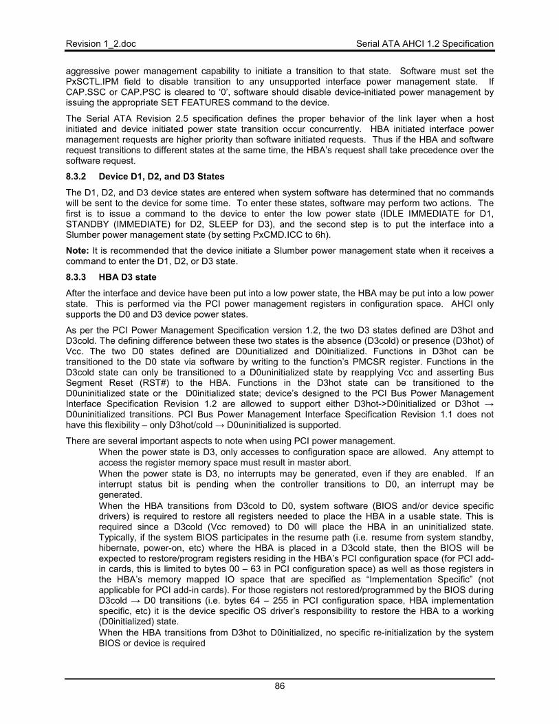
Revision 1_2.doc Serial ATA AHCI 1.2 Specification
86
aggressive power management capability to initiate a transition to that state. Software must set the PxSCTL.IPM field to disable transition to any unsupported interface power management state. If CAP.SSC or CAP.PSC is cleared to ‘0’, software should disable device-initiated power management by issuing the appropriate SET FEATURES command to the device.
The Serial ATA Revision 2.5 specification defines the proper behavior of the link layer when a host initiated and device initiated power state transition occur concurrently. HBA initiated interface power management requests are higher priority than software initiated requests. Thus if the HBA and software request transitions to different states at the same time, the HBA’s request shall take precedence over the software request.
8.3.2 Device D1, D2, and D3 States
The D1, D2, and D3 device states are entered when system software has determined that no commands will be sent to the device for some time. To enter these states, software may perform two actions. The first is to issue a command to the device to enter the low power state (IDLE IMMEDIATE for D1, STANDBY (IMMEDIATE) for D2, SLEEP for D3), and the second step is to put the interface into a Slumber power management state (by setting PxCMD.ICC to 6h).
Note: It is recommended that the device initiate a Slumber power management state when it receives a command to enter the D1, D2, or D3 state.
8.3.3 HBA D3 state
After the interface and device have been put into a low power state, the HBA may be put into a low power state. This is performed via the PCI power management registers in configuration space. AHCI only supports the D0 and D3 device power states.
As per the PCI Power Management Specification version 1.2, the two D3 states defined are D3hot and D3cold. The defining difference between these two states is the absence (D3cold) or presence (D3hot) of Vcc. The two D0 states defined are D0unitialized and D0initialized. Functions in D3hot can be transitioned to the D0 state via software by writing to the function’s PMCSR register. Functions in the D3cold state can only be transitioned to a D0uninitialized state by reapplying Vcc and asserting Bus Segment Reset (RST#) to the HBA. Functions in the D3hot state can be transitioned to the D0uninitialized state or the D0initialized state; device’s designed to the PCI Bus Power Management Interface Specification Revision 1.2 are allowed to support either D3hot->D0initialized or D3hot →D0uninitialized transitions. PCI Bus Power Management Interface Specification Revision 1.1 does not have this flexibility – only D3hot/cold → D0uninitialized is supported.
There are several important aspects to note when using PCI power management. • When the power state is D3, only accesses to configuration space are allowed. Any attempt to
access the register memory space must result in master abort. • When the power state is D3, no interrupts may be generated, even if they are enabled. If an
interrupt status bit is pending when the controller transitions to D0, an interrupt may be generated.
• When the HBA transitions from D3cold to D0, system software (BIOS and/or device specific drivers) is required to restore all registers needed to place the HBA in a usable state. This is required since a D3cold (Vcc removed) to D0 will place the HBA in an uninitialized state. Typically, if the system BIOS participates in the resume path (i.e. resume from system standby, hibernate, power-on, etc) where the HBA is placed in a D3cold state, then the BIOS will be expected to restore/program registers residing in the HBA’s PCI configuration space (for PCI add-in cards, this is limited to bytes 00 – 63 in PCI configuration space) as well as those registers in the HBA’s memory mapped IO space that are specified as “Implementation Specific” (not applicable for PCI add-in cards). For those registers not restored/programmed by the BIOS during D3cold → D0 transitions (i.e. bytes 64 – 255 in PCI configuration space, HBA implementation specific, etc) it is the device specific OS driver’s responsibility to restore the HBA to a working (D0initialized) state.
• When the HBA transitions from D3hot to D0initialized, no specific re-initialization by the system BIOS or device is required
Serial ATA AHCI 1.2 Specification Revision 1_2.doc
87
• When the HBA transitions from D3hot to D0unitialized, then re-initialization of the device is performed exclusively by the device specific OS driver(s) – no system BIOS assistance is required.
Software must disable interrupts (GHC.IE must be cleared to ‘0’) prior to requesting a transition of the HBA to the D3 state. This precaution by software avoids an interrupt storm if an interrupt occurs during the transition to the D3 state.
PxCMD.ST must be cleared to ‘0’ before entry into the D3 power state.
8.4 PME
When the HBA is in the D3 state, it may optionally wake based on a change in the device state.
PME must be generated when the HBA is in the D3 state under the following conditions: • PxIS.PCS is set to ‘1’ due to a native hot plug insertion • PxIS.DMPS set, indicating a mechanical presence switch has been opened or closed • PxIS.CPDS set, indicating cold presence detect state change • Set Device Bits FIS received on the interface with the ‘I’ bit set to ‘1’. The HBA may
require that the Notification (‘N’) bit also be set to ‘1’ in the Set Device Bits FIS; this is implementation specific.
If any of these bits are set, regardless of the setting of the enables in PxIE and GHC.IE, the HBA shall generate PME#.
Revision 1_2.doc Serial ATA AHCI 1.2 Specification
88
9 Port Multiplier Support Port Multiplier support for HBAs is optional, and its support is indicated to system software via CAP.SPM. If Port Multipliers are supported in the HBA, it must support command-based switching. This section describes the hardware and software differences necessary to make a Port Multiplier work.
9.1 Command Based Switching
In this mode of operation, a communication path is opened between the HBA and a device through the Port Multiplier. Since Port Multipliers are meant to be simple, the burden of making a connection is on AHCI software, to ensure that multiple commands are not outstanding to different devices behind the Port Multiplier.
9.1.1 Non-Queued Operation
When running non-queued commands, the command list may be filled with any combination of ports, and each command list entry can target a different port. There is no fixed relationship between number of commands allocated to the device and the number of devices behind a Port Multiplier. For example, 29 commands could be allocated to the device behind PM port #0,and 3 commands for the remaining devices, if that is desired by system software.
Since the commands are non-queued, the HBA shall execute each command entry in its entirety before moving to the next entry in the command list, which may include a command to a different port.
This places special burden on system software for building commands. Since the HBA operates in order in its command list, system software should not fill the list in sequential order with commands to a single device; otherwise another device may get starved. Take the following example:
• 4 devices attached to a PM behind a port • The operating system presents several commands
o 4 to the device behind PM port #0 o 2 to the device behind PM port #1 o 1 to the device behind PM port #2
If the AHCI software placed these commands in sequential order, starting at command slot 0, the list would look as follows:
• Slot #0: PM Port #0, Command 1 • Slot #1: PM Port #0, Command 2 • Slot #2: PM Port #0, Command 3 • Slot #3: PM Port #0, Command 4 • Slot #4: PM Port #1, Command 1 • Slot #5: PM Port #1, Command 2 • Slot #6: PM Port #2, Command 1
This would cause the device behind port #2 to not execute its command for a very long time. In the worst case scenario, 31 commands to other devices behind different PM ports may execute before this command is allowed to execute.
A better placement of commands to result in fairer execution would be as follows: • Slot #0: PM Port #0, Command 1 • Slot #1: PM Port #1, Command 1 • Slot #2: PM Port #2, Command 1 • Slot #8: PM Port #0, Command 2 • Slot #9: PM Port #1, Command 2 • Slot #16: PM Port #0, Command 3 • Slot #24: PM Port #0, Command 4
Mapping commands in this fashion helps ensure that the device behind PM port #2 has a fairer chance of executing. The above algorithm results in round-robin execution of commands. Many algorithms for fairness exist, and their implementations are beyond the scope of this specification.
Serial ATA AHCI 1.2 Specification Revision 1_2.doc
89
In order to find the best slot for placing the next command, software should use PxCMD.CCS to find the current slot the HBA is executing, and place the command in an appropriate slot for the fairness algorithm that is desired.
9.1.2 Queued Operation
Since queued commands result in two different operations (command issue, clear of BSY, then data transfer), if commands were sent to different ports, the Port Multiplier may issue FISes back to the HBA in an interleaved manner from different ports. This will break an HBA that only supports command-based switching. Therefore, when executing native command queuing commands, system software must only add commands to the command list that target a single port behind the Port Multiplier, wait for the commands to finish (PxSACT bits all cleared), then add commands for a different port. Additionally, the tags used must match the command slot entries.
9.2 Port Multiplier Enumeration
In order to enumerate a Port Multiplier, a software reset is issued to port 0Fh (control port) on the Port Multiplier. If the signature returned corresponds to a Port Multiplier, then a Port Multiplier is attached. If the signature returned corresponds to another device type, then a Port Multiplier is not attached.
To reliably enumerate the Port Multiplier, regardless of the presence of a device on Port Multiplier device port 0, the PxCMD.CLO (command list override) bit should be used if this feature is supported by the HBA (indicated by CAP.SCLO being set to ‘1’). Software should ensure that the PxCMD.ST bit is ‘0’. Then software should construct the two Register FISes required for a software reset in the command list, where the PM Port field value in the Register FIS is set to 0Fh. After constructing the FISes in the command list, software should set PxCMD.CLO to ‘1’ to force the BSY and DRQ bits in the Status register to be cleared. Then software should set the PxCMD.ST bit to ‘1’ and set appropriate PxCI bits in order to begin execution of the software reset command.
If the CAP.SCLO bit is cleared to ‘0’, a Port Multiplier can only be enumerated after a device on Port Multiplier device port 0 sends a Register FIS to the host that clears PxTFD.STS.BSY and PxTFD.STS.DRQ to ‘0’.
9.3 FIS-based Switching
FIS-based switching requires the HBA to keep track of additional device specific context within each HBA port. The HBA must be able to issue commands to a device while there are still commands outstanding to other devices that are connected to the same host port through the Port Multiplier. The HBA must be able to switch DMA context on the fly; e.g. a Data FIS is received from target X, followed by a Data FIS from target X+1. The next sections outline unique portions of FIS-based switching that are different from normal operation.
9.3.1 Configuration
To enable use of FIS-based switching, software shall set the PxFBS.EN bit to ‘1’ while PxCMD.ST is cleared to ‘0’. The host shall ensure that the requirements for setting PxCMD.ST to ‘1’ (listed in section 10.3.1) are met prior to setting PxFBS.EN to ‘1’. At some later point when software is ready to issue commands to the device, software will set the PxCMD.ST bit to ‘1’ and then begin issuing commands to the device(s).
To disable use of FIS-based switching, software shall clear the PxCMD.ST bit to ‘0’ and subsequently clear the PxFBS.EN bit to ‘0’. This sequence ensures that the port is in a quiescent state prior to disabling use of FIS-based switching.
9.3.1.1 PxFBS Control Register Details
9.3.1.1.1 Enable
When FIS-based switching is enabled, the hardware shall maintain a distinct BSY/DRQ bit for up to 16 devices. These bits are distinguished in the state machine as the pBsy and pDrq arrays. Hardware shall fetch commands in such a way as to try to ensure commands are issued to all devices that have BSY/DRQ cleared to ‘0’ and have commands in the command list. Instances of the BSY/DRQ bits are updated based on the Port Multiplier port field in Device to Host FISes.
Revision 1_2.doc Serial ATA AHCI 1.2 Specification
90
Note that hardware does not need to maintain a distinct ERR bit for each device. Only one device may have its PxTFD.STS.ERR bit set at a time since the hardware shall stop when an error condition occurs.
When FIS-based switching is disabled, the hardware shall maintain a single instance of the BSY/DRQ/ERR bits and shall not distinguish setting/clearing these bits based on Port Multiplier port value in a Device to Host FIS.
9.3.1.1.2 Device Error Clear
Device Error Clear is used when hardware signals a single device error has occurred by setting PxFBS.SDE to ‘1’. If PxFBS.SDE is cleared to ‘0’, then software setting PxFBS.DEC to ‘1’ has indeterminate results. When software sets PxFBS.DEC to ‘1’, hardware shall take the following actions for PM port X (the value in PxFBS.DWE).
• Clear all PxCI and PxSACT bits that correspond to commands for PM port X
• Clear all internal state that corresponds to commands for PM port X
• Clear pBsy[X] and pDrq[X] to ‘0’
Note that hardware shall not modify error bits set in PxIS; it is up to software to clear these bits appropriately.
After completing error recovery actions and clearing the register bits noted, hardware shall clear PxFBS.DEC to ‘0’. At this point, hardware shall begin processing/executing commands from other PM ports that are still outstanding and newly issued commands.
9.3.1.1.3 Device To Issue
The PxFBS.DEV field must be filled in by software correctly prior to writing the PxCI register. Note that this value need not be set prior to writing the PxSACT register in the case of NCQ. The value in PxFBS.DEV shall correspond to the value in the Port Multiplier port field of the command header for the command issued on the write to PxCI.
This field only needs to be written on changes to the device to issue the next command to. It does not need to be updated prior to every PxCI register write unless there is a change in the device to issue the command to. Note that commands cannot be issued to multiple devices simultaneously, as only one device may be identified in the Device to Issue field.
9.3.1.1.4 Active Device Optimization
The PxFBS.ADO field is used by the HBA to indicate the number of active devices that the implementation has been optimized for. As an example, mid-range HBAs may optimize for up to four drives attached on a Port Multiplier due to the typical size of enclosures the HBA is used with. For optimal performance, software should limit the number of active devices (devices with commands outstanding at the same time) based on this value.
The HBA is required to correctly operate when there are more devices active than indicated in this field. However, in this condition the overall performance may degrade.
9.3.1.1.5 Command Issue
9.3.1.1.5.1 Non-queued Commands
Non-queued commands may use any command slot. The HBA guarantees that command issue order is preserved, so software does not need to ensure any ordering of command slots.
To issue a non-queued command, the host should:
• Select an unused command slot • Build the command table and command header • Set PxFBS.DEV to the value of the Port Multiplier port field in the command header • Set the bit in PxCI that corresponds to the command slot being used
Serial ATA AHCI 1.2 Specification Revision 1_2.doc
91
9.3.1.1.5.2 Native Queued Commands
Software shall ensure that the NCQ tag corresponds to the command slot that the command is placed in.
To issue an NCQ command, the host should:
• Select an unused command slot • Build the command table and command header, ensuring that the NCQ tag matches the slot
number • Set PxFBS.DEV to the value of the Port Multiplier port field in the command header • Set the bit in PxSACT that corresponds to the command slot being used • Set the bit in PxCI that corresponds to the command slot being used
9.3.2 Command Ordering
When FIS-based switching is enabled (PxFBS.EN is set to ‘1’) then host hardware is responsible for ensuring the command issue order for a particular device is maintained.
If multiple commands are issued to the same device by software in a single write of the PxCI register, the transmission order amongst that set of commands is arbitrary. To ensure a particular order of issue for a set of commands, the commands shall be issued by software in distinct writes of the PxCI register.
There is no command ordering requirements among commands being issued to separate Port Multiplier ports. The only requirement is that the HBA ensure that commands for all devices are executed in a manner that avoids starvation of any device. It is recommended that the HBA give priority to commands issued to the control port.
9.3.3 FIS Receive Area
When using FIS-based switching, software shall allocate a FIS receive area that is 16 times larger than the normal FIS receive area size. The allocated FIS receive area shall be 256 bytes * 16 = 4KB in size. The PxFB address for the FIS receive area is required to be 4KB aligned when using FIS-based switching.
When a non-Data FIS is received that should be copied in the FIS receive area, it will be copied into the appropriate spot in the FIS receive area based on both the type of the FIS and the Port Multiplier port field in the received FIS. The Port Multiplier port field in the FIS shall be used as an index into the FIS receive area; PxFB/U[PM Port field * 256 bytes] shall be the base location for the FIS receive area that the FIS should be copied into. Once the base location of the target’s FIS receive area is identified, the FIS is copied to the appropriate offset based on the offsets specified in section 4.2.1. Note: There is an exception for receiving an Unknown FIS. An Unknown FIS is always placed in the FIS receive area for PM port 0.
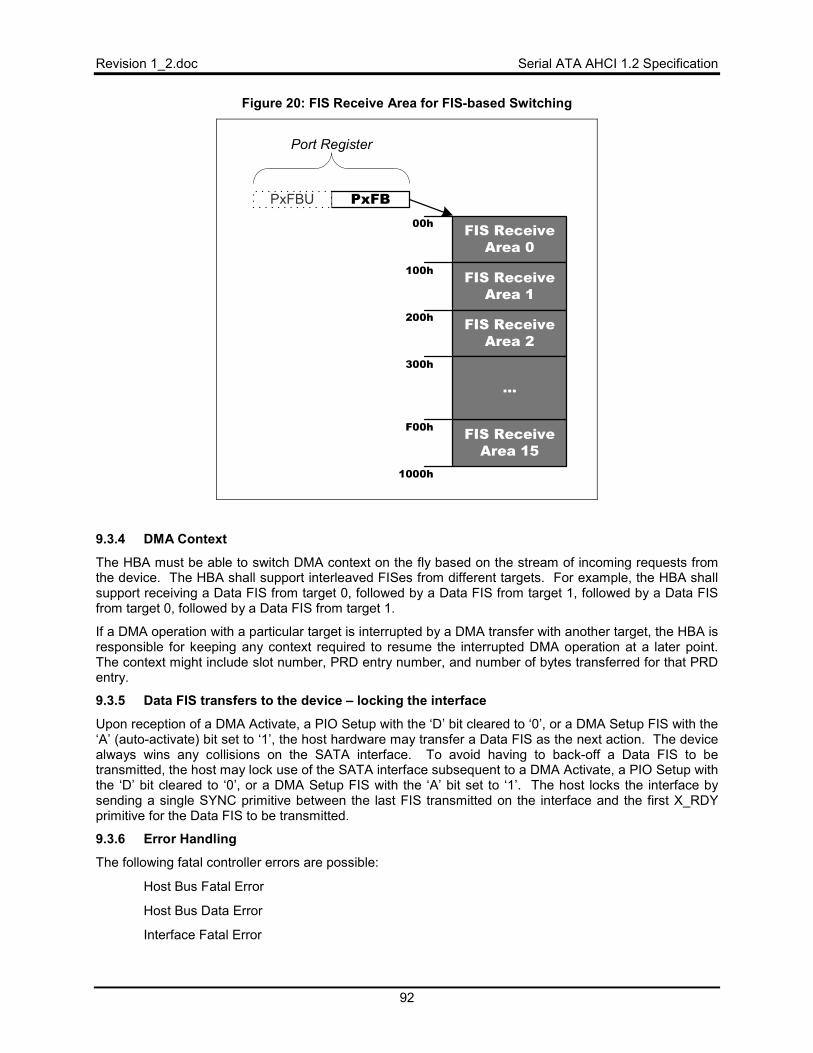
Revision 1_2.doc Serial ATA AHCI 1.2 Specification
92
Figure 20: FIS Receive Area for FIS-based Switching
PxFB
FIS ReceiveArea 0
FIS ReceiveArea 1
FIS ReceiveArea 2
FIS ReceiveArea 15
PxFBU
Port Register
...
00h
100h
200h
300h
F00h
1000h
9.3.4 DMA Context
The HBA must be able to switch DMA context on the fly based on the stream of incoming requests from the device. The HBA shall support interleaved FISes from different targets. For example, the HBA shall support receiving a Data FIS from target 0, followed by a Data FIS from target 1, followed by a Data FIS from target 0, followed by a Data FIS from target 1.
If a DMA operation with a particular target is interrupted by a DMA transfer with another target, the HBA is responsible for keeping any context required to resume the interrupted DMA operation at a later point. The context might include slot number, PRD entry number, and number of bytes transferred for that PRD entry.
9.3.5 Data FIS transfers to the device – locking the interface
Upon reception of a DMA Activate, a PIO Setup with the ‘D’ bit cleared to ‘0’, or a DMA Setup FIS with the ‘A’ (auto-activate) bit set to ‘1’, the host hardware may transfer a Data FIS as the next action. The device always wins any collisions on the SATA interface. To avoid having to back-off a Data FIS to be transmitted, the host may lock use of the SATA interface subsequent to a DMA Activate, a PIO Setup with the ‘D’ bit cleared to ‘0’, or a DMA Setup FIS with the ‘A’ bit set to ‘1’. The host locks the interface by sending a single SYNC primitive between the last FIS transmitted on the interface and the first X_RDY primitive for the Data FIS to be transmitted.
9.3.6 Error Handling
The following fatal controller errors are possible:
• Host Bus Fatal Error
• Host Bus Data Error
• Interface Fatal Error
Serial ATA AHCI 1.2 Specification Revision 1_2.doc
93
• Task File Error
A host bus error is considered fatal to the host port (and all devices attached to that port). If the Host Bus Fatal Error or Host Bus Data Error occurs, then host software shall follow the non-device specific error recovery procedure.
An interface fatal error may be localized to a particular device or may be fatal to the entire port. For example, a SYNC escape issued by the Port Multiplier in response to a transmitted non-Data FIS from the host is considered fatal to the particular device only. However, a CRC error for a Data FIS may be considered fatal to the entire port. If the error is fatal to a particular device only, then the hardware shall set the PxFBS.SDE bit to ‘1’ and shall indicate the device that had the error in PxFBS.DWE. If the error is fatal to the entire port, then PxFBS.SDE shall be cleared to ‘0’ by the hardware. Software should follow either the device specific or non-device specific error procedure depending on whether PxFBS.SDE is set to ‘1’.
A taskfile error condition is fatal for the impacted device only. After the PxTFD.STS.ERR bit is set to ‘1’, host hardware shall pause command execution and shall not begin reception or start transmission of any further FISes to/from the Port Multiplier. To recover from this error condition, software shall follow the device specific error recovery procedure.
After recovering from an error condition and a reset has not yet been issued to the impacted device(s), the HBA may receive FISes that correspond to commands that were flushed by the host controller as part of the error recovery. If a Data or non-Data FIS for a non-existent command is received, the HBA shall respond to that FIS with an R_OK and then shall discard the FIS. No error bits are set in this case.
9.3.6.1 Error Recovery from Device Specific Errors
In the case of a device specific error (PxFBS.SDE = ‘1’), the host controller will pause execution of commands for all other devices until software acknowledges and clears the error condition. Host software shall set the PxFBS.DEC bit to ‘1’ to clear the error condition for the particular device. The PxTFD register shall not be modified by the HBA due to PxFBS.DEC being set to ‘1’. The internal pBsy and pDrq variables for the device in error shall be cleared to zero.
When hardware clears PxFBS.DEC to ‘0’, the error condition has been cleared within the host controller. Software should then issue a software reset (or COMRESET if necessary) to the device that experienced the error to ensure that the device is in a known state. After PxFBS.DEC is cleared to ‘0’, software may begin issuing new commands to all devices and hardware resumes execution of paused commands for other devices.
If PxFBS.DEC does not clear to ‘0’ or software experiences additional timeouts, then software should follow the error recovery procedures for non-device specific errors.
9.3.6.2 Error Recovery from Non-Device Specific Errors
In the case of a non-device specific error (PxFBS.SDE = ‘0’), all commands for the port need to be flushed and each device that had commands outstanding needs to be reset. Host software shall clear the PxCMD.ST bit to ‘0’ to recover from the error. When PxCMD.ST is transitions from ‘1’ to ‘0’, the internal pBsy and pDrq variables are cleared to zero. All devices that had commands outstanding at the time of the error shall be reset by the host using a software reset to that device (or a COMRESET if necessary).
9.3.6.3 Incorrect Port Multiplier Status
The PxIS.IPMS bit retains meaning with FIS-based switching. The IPMS bit is set whenever a FIS is received from a device that does not have a command outstanding. The IPMS bit is not set when an asynchronous notification is received.
Revision 1_2.doc Serial ATA AHCI 1.2 Specification
94
9.3.7 PxTFD Register Information
The PxTFD register is updated whenever a FIS is received from any attached device that updates the Status and Error registers and either the BSY or DRQ bits is currently set in PxTFD.STS. Note that when there are commands outstanding to multiple devices, the PxTFD register could be updated by any of those devices. Thus, the host should not refer to the PxTFD register during the course of normal operation when using FIS-based switching.
To determine if a command is completed or still outstanding, the host should refer to the PxCI and PxSACT register. It is unsafe to refer to the PxTFD register to determine command completion when doing FIS-based switching. The only case where it is safe to refer to the PxTFD register is when commands are outstanding to only one device. In this situation, the PxTFD register is only being updated by a single device and the results will be coherent.
When a taskfile error occurs (PxIS.TFES is set to ‘1’), the host may refer to the values in PxTFD. The values in PxTFD at this time are guaranteed to correspond to the device that reported the taskfile error condition.
9.3.8 SYNC Escape and setting the ‘R’ bit in Command Headers
When FIS-based switching is enabled (PxFBS.EN = ‘1’), the host shall not set the ‘R’ bit in the command header for any command. Setting the ‘R’ bit causes the host to issue a SYNC Escape on the interface prior to transmitting the Command FIS. When using FIS-based switching, SYNC Escapes shall not be issued by the host since any FIS reception that is aborted may be from an entirely different device. A SYNC Escape may be issued by the Port Multiplier or the device under certain error conditions.
In the case where the host cannot recover the link effectively, the next step is to issue a COMRESET to the host port and re-enumerate the Port Multiplier. Issuing a COMRESET to the host port will cause all attached devices to be reset.
9.3.9 FIS-based switching and Device Enumeration
When a host is using FIS-based switching and becomes aware that a new device has been attached (by polling the SError.DIAG.X bits in the Port Multiplier or via asynchronous notification), the host should enumerate the newly attached device by the procedure outlined in this section.
After becoming aware that a new device is attached, the host should complete all outstanding commands to other devices attached to the Port Multiplier. The next step is then to clear the SError.DIAG.X bit for the newly attached device in the corresponding SError register within the Port Multiplier. To get the signature for the newly attached device, a software reset needs to be issued to that device.
Prior to issuing the software reset, software shall clear PxCMD.ST to ‘0’ and then clear PxFBS.EN to ‘0’. While PxFBS.EN is cleared to ‘0’, PxCMD.ST should be set to ‘1’ in order to issue the software reset. Software may then issue the software reset to the newly attached device, with the appropriate PM port field. After enumerating the device and no additional commands are outstanding on the Port Multiplier, the host may then re-enter FIS-based switching mode. To re-enter FIS-based switching mode, the host clears PxCMD.ST to ‘0’, then sets PxFBS.EN to ‘1’, and then sets PxCMD.ST to ‘1’.
Serial ATA AHCI 1.2 Specification Revision 1_2.doc
95
10 Platform Communication 10.1 Software Initialization of HBA
Before any useful work can be performed, the HBA must be initialized. Initialization consists of two independent phases: a firmware phase (platform BIOS) and a system software phase. Initialization of the HBA’s PCI configuration space is beyond the scope of this specification.
10.1.1 Firmware Specific Initialization
To aid system software during runtime, the BIOS shall ensure that the following registers are initialized to values that are reflective of the capabilities supported by the platform. Firmware shall always initialize the following registers and values:
• CAP.SSS (support for staggered spin-up) • CAP.SMPS (support for mechanical presence switches) • PI (ports implemented) • PxCMD.HPCP (whether port is hot plug capable). Firmware shall initialize the HPCP bit for each
port implemented on the platform (as defined by the PI register). The PxCMD.HPCP should be set to ‘1’ if PxCMD.MPSP or PxCMD.CPD is set to ‘1’ for the port.
• PxCMD.MPSP (whether mechanical presence switch is attached to the port). Firmware shall initialize the MPSP bit for each port implemented on the platform (as defined by the PI register).
• PxCMD.CPD (whether cold presence detect logic is attached to the port). Firmware shall initialize the CPD bit for each port implemented on the platform (as defined by the PI register).
After firmware has initialized the aforementioned registers, it shall then perform the following steps to complete the staggered spin-up process (if applicable to the platform) on each port implemented by the AHCI HBA (as indicated by the PI register):
1. Indicate that system software is AHCI aware by setting GHC.AE to ‘1’.
2. Ensure that PxCMD.ST = ‘0’, PxCMD.CR = ‘0’, PxCMD.FRE = ‘0’, PxCMD.FR = ‘0’, and PxSCTL.DET = ‘0h’.
3. Allocate memory for the command list and the FIS receive area. Set PxCLB and PxCLBU to the physical address of the allocated command list. Set PxFB and PxFBU to the physical address of the allocated FIS receive area. Then set PxCMD.FRE to ‘1’.
4. Initiate a spin up of the SATA drive attached to the port; i.e. set PxCMD.SUD to ‘1’. 5. Wait for a positive indication that a device is attached to the port (the maximum amount
of time to wait for presence indication is specified in the Serial ATA Revision 2.5 specification). This is done by polling PxSSTS.DET. If PxSSTS.DET returns a value of 1h or 3h when read, then system software shall continue to the next step, otherwise if the polling process times out system software moves to the next implemented port and returns to step 1.
6. Clear the PxSERR register, by writing ‘1s’ to each implemented bit location. 7. Wait for indication that SATA drive is ready. This is determined via an examination of
PxTFD.STS. If PxTFD.STS.BSY, PxTFD.STS.DRQ, and PxTFD.STS.ERR are all ‘0’, prior to the maximum allowed time as specified in the ATA/ATAPI-7 specification, the device is ready.
10.1.2 System Software Specific Initialization
This section describes how system software places the AHCI HBA into a minimally initialized state. Because the term “system software” is used to collectively reference both the platform BIOS and operating system, this section applies to any software that is AHCI aware. Note that some steps may not be required for system BIOS (e.g. ensuring that the controller is not running) since the host controller will be in a known state following a system reset. Additionally, if system BIOS already allocated memory for and initialized the appropriate registers for the command list and FIS receive area, it may skip this step of the process. Software may perform an HBA reset prior to initializing the controller by setting GHC.AE to ‘1’ and then setting GHC.HR to ‘1’ if desired.
Revision 1_2.doc Serial ATA AHCI 1.2 Specification
96
To place the AHCI HBA into a minimally initialized state, system software shall:
1. Indicate that system software is AHCI aware by setting GHC.AE to ‘1’. 2. Determine which ports are implemented by the HBA, by reading the PI register. This bit
map value will aid software in determining how many ports are available and which port registers need to be initialized.
3. Ensure that the controller is not in the running state by reading and examining each implemented port’s PxCMD register. If PxCMD.ST, PxCMD.CR, PxCMD.FRE and PxCMD.FR are all cleared, the port is in an idle state. Otherwise, the port is not idle and should be placed in the idle state prior to manipulating HBA and port specific registers. System software places a port into the idle state by clearing PxCMD.ST and waiting for PxCMD.CR to return ‘0’ when read. Software should wait at least 500 milliseconds for this to occur. If PxCMD.FRE is set to ‘1’, software should clear it to ‘0’ and wait at least 500 milliseconds for PxCMD.FR to return ‘0’ when read. If PxCMD.CR or PxCMD.FR do not clear to ‘0’ correctly, then software may attempt a port reset or a full HBA reset to recover.
4. Determine how many command slots the HBA supports, by reading CAP.NCS. 5. For each implemented port, system software shall allocate memory for and program:
• PxCLB and PxCLBU (if CAP.S64A is set to ‘1’) • PxFB and PxFBU (if CAP.S64A is set to ‘1’)
It is good practice for system software to ‘zero-out’ the memory allocated and referenced by PxCLB and PxFB. After setting PxFB and PxFBU to the physical address of the FIS receive area, system software shall set PxCMD.FRE to ‘1’.
6. For each implemented port, clear the PxSERR register, by writing ‘1s’ to each implemented bit location.
7. Determine which events should cause an interrupt, and set each implemented port’s PxIE register with the appropriate enables. To enable the HBA to generate interrupts, system software must also set GHC.IE to a ‘1’.
Note: Due to the multi-tiered nature of the AHCI HBA’s interrupt architecture, system software must always ensure that the PxIS (clear this first) and IS.IPS (clear this second) registers are cleared to ‘0’ before programming the PxIE and GHC.IE registers. This will prevent any residual bits set in these registers from causing an interrupt to be asserted.
At this point the HBA is in a minimally initialized state. System software may provide additional programming of the GHC register and port PxCMD and PxSCTL registers based on the policies of the operating system and platform – these details are beyond the scope of this specification.
Software shall not set PxCMD.ST to ‘1’ until it is determined that a functional device is present on the port as determined by PxTFD.STS.BSY = ‘0’, PxTFD.STS.DRQ = ‘0’, and PxSSTS.DET = 3h. Note that to enable the PxTFD register to be updated with the initial Register FIS for a port, the PxSERR.DIAG.X bit must be cleared to ‘0’.
10.2 Hardware Prerequisites to Enable/Disable GHC.AE
When a legacy interface is supported in addition to AHCI (CAP.SAM = ‘0’), software may desire to switch from one mode to the other. Actively switching between AHCI and a legacy mode is strongly discouraged due to OS sensitivity to the class code used by the controller. This section lists hardware requirements only for switching between AHCI mode and a legacy mode, it does not comprehend any software considerations.
To switch from legacy mode to AHCI mode, the legacy interface shall be in an idle state and there should be no outstanding commands to any devices connected to the controller. Additionally, any transaction errors reported through the legacy task file status register (i.e. ERR == '1') shall be rectified prior to switching to AHCI mode. This can be accomplished via a software reset. At this point, software can begin the sequence for initializing the AHCI controller outlined in section 10.1.
Serial ATA AHCI 1.2 Specification Revision 1_2.doc
97
To switch from AHCI mode to legacy mode, the AHCI controller must be brought to an idle state for all ports and there should be no outstanding commands to any devices connected to the controller. The PxCMD.ST should be cleared to ‘0’ for all ports and software should ensure that the PxCMD.CR bit is cleared to ‘0’ for all ports. The PxCMD.FRE bit should be cleared to ‘0’ for all ports and software should ensure that PxCMD.FR is cleared to ‘0’ for all ports. Then software should clear the GHC.IE bit to ‘0’ to ensure there are no interrupts that occur on the AHCI controller. At this point, software may set the GHC.AE bit to ‘0’. After clearing the GHC.AE bit to ‘0’, software should then issue a COMRESET to each SATA port to ensure that the legacy controller recognizes whether a drive is present on the port, and if so then captures its signature. Commands may be issued at this point to the legacy controller. Software shall initialize the devices after switching modes.
10.3 Software Manipulation of Port DMA Engines
Each port contains two major DMA engines. One DMA engine walks through the command list, and is controlled by PxCMD.ST. The second DMA engine copies received FISes into system memory, and is controlled by PxCMD.FRE.
10.3.1 Start (PxCMD.ST)
When PxCMD.ST is set to ‘1’, software is limited in what actions it is allowed to perform on the port (refer to section 5.3.2.3).
• It shall not manipulate PxCMD.POD to power on or off a device through cold presence detect logic (if supported by the HBA).
• It shall not manipulate PxSCTL.DET to change the Phy state • It shall not manipulate PxCMD.SUD to spin-up the device (if supported by the HBA)
The above actions are only allowed while the HBA is idle, indicated by both PxCMD.ST and PxCMD.CR being equal to ‘0’. This is noted by the HBA state machine H:NotRunning state. If software performs any of the above actions while the port is not idle (PxCMD.ST or PxCMD.CR are set to ‘1’), indeterminate results may occur.
Software shall not set PxCMD.ST to ‘1’ until it verifies that PxCMD.CR is ‘0’ and has set PxCMD.FRE to ‘1’. Additionally, software shall not set PxCMD.ST to ‘1’ until a functional device is present on the port (as determined by PxTFD.STS.BSY = ‘0’, PxTFD.STS.DRQ = ‘0’, and (PxSSTS.DET = 3h, or PxSSTS.IPM = 2h or 6h)) and PxCLB/PxCLBU are programmed to valid values.
Before the HBA enters the low power D3 state, software shall clear PxCMD.ST to ‘0’.
10.3.2 FIS Receive Enable (PxCMD.FRE)
When PxCMD.FRE is set (causing PxCMD.FR to be set to ‘1’), the HBA receives FISes from the device and copies them into system memory. When PxCMD.FRE is cleared (causing PxCMD.FR to be cleared to ‘0’), received FISes are held internally, and if the HBA’s internal FIFO is full, further FIS reception is blocked.
Software is allowed to manipulate PxCMD.FRE so that it may move the FIS receive area to a new location. When this bit is cleared to ‘0’, software must first wait for PxCMD.FR to clear to ‘0’, indicating that the DMA engine for FIS reception is in an idle condition. When PxCMD.FR and PxCMD.FRE are both cleared to ‘0’, software may update the values of PxFB and PxFBU. Prior to setting PxCMD.FRE to ‘1’, software shall ensure that PxFB and PxFBU are set to valid values. Software shall not write PxFB and PxFBU while PxCMD.FRE is set to ‘1’.
Software shall set this bit to ‘1’ prior to setting PxCMD.ST to ‘1’. Software shall not clear this bit while PxCMD.ST or PxCMD.CR is set to ‘1’.
Upon HBA reset, this bit is cleared. The D2H Register FIS containing the device signature shall be accepted by the HBA, and the signature field updated.
Note that if the HBA stops running due to an error (for example, PxIS.IFS is set to ‘1’), FISes may not be posted until the PxCMD.ST bit is cleared to ‘0’ to recover from the error.
Revision 1_2.doc Serial ATA AHCI 1.2 Specification
98
10.4 Reset
AHCI supports three levels of reset: • Software – a single device on one of the ports is reset, but the HBA and physical communication
remain intact. This is the least intrusive. • Port – the physical communication between the HBA and device on a port are disabled. This is
more intrusive • HBA – the entire HBA is reset, and all ports are disabled. This is the most intrusive.
When an HBA or port reset occurs, Phy communication shall be re-established with the device through a COMRESET followed by the normal out-of-band communication sequence defined in Serial ATA. At the end of the reset, the device, if working properly, will send a D2H Register FIS, which contains the device signature. When the HBA receives this FIS, it updates PxTFD.STS and PxTFD.ERR register fields, and updates the PxSIG register with the signature.
Software is recommended to follow a staggered reset approach, starting from a less intrusive reset mechanism and then using a more intrusive reset mechanism only if the less intrusive mechanism does not succeed in clearing the condition.
10.4.1 Software Reset
Legacy software contained a standard mechanism for generating a reset to a Serial ATA device – setting the SRST (software reset) bit in the Device Control register. Serial ATA has a more robust mechanism called COMRESET, also referred to as port reset. A port reset is the preferred mechanism for error recovery and should be used in place of software reset.
To issue a software reset in AHCI, software builds two H2D Register FISes in the command list. The first Register FIS has the SRST bit set to ‘1’ in the Control field of the Register FIS, the ‘C’ bit is set to ‘0’ in the Register FIS, and the command table has the CH[R] (reset) and CH[C] (clear BSY on R_OK) bits set to ‘1’. The CH[R] (reset) bit causes the HBA to perform a SYNC escape if necessary to put the device into an idle condition before sending the software reset. The CH[C] (clear BSY on R_OK) bit needs to be set for the first Register FIS to clear the BSY bit and proceed to issue the next Register FIS since the device does not send a response to the first Register FIS in a software reset sequence. The second Register FIS has the SRST bit set to ‘0’ in the Control field of the Register FIS, the ‘C’ bit is set to ‘0’ in the Register FIS, and the command table has the CH[R] (reset) and CH[C] (clear BSY on R_OK) bits cleared to ‘0’. Refer to the Serial ATA Revision 2.5 specification for more information on the software reset FIS sequence.
When issuing a software reset sequence, there should not be other commands in the command list. Before issuing the software reset, software must clear PxCMD.ST, wait for the port to be idle (PxCMD.CR = ‘0’), and then re-set PxCMD.ST. PxTFD.STS.BSY and PxTFD.STS.DRQ must be cleared prior to issuing the reset. If PxTFD.STS.BSY or PxTFD.STS.DRQ is still set based on the failed command, then a port reset should be attempted or command list override (PxCMD.CLO) should be used if supported.
Note that a device-to-host FIS from a previously failed command may be received after the PxCMD.ST bit has been cleared and/or re-set. It is recommended that the HBA ignore such a FIS or SYNC Escape that FIS (as directed by the CH[R] bit being set in the first software reset H2D Register FIS).
10.4.2 Port Reset
If a port is not functioning properly after a software reset, software may attempt to re-initialize communication with the port via a COMRESET. It must first clear PxCMD.ST, and wait for PxCMD.CR to clear to ‘0’ before re-initializing communication. However, if PxCMD.CR does not clear within a reasonable time (500 milliseconds), it may assume the interface is in a hung condition and may continue with issuing the port reset.
Software causes a port reset (COMRESET) by writing 1h to the PxSCTL.DET field to invoke a COMRESET on the interface and start a re-establishment of Phy layer communications. Software shall wait at least 1 millisecond before clearing PxSCTL.DET to 0h; this ensures that at least one COMRESET signal is sent over the interface. After clearing PxSCTL.DET to 0h, software should wait for

Serial ATA AHCI 1.2 Specification Revision 1_2.doc
99
communication to be re-established as indicated by bit 0 of PxSSTS.DET being set to ‘1’. Then software should write all 1s to the PxSERR register to clear any bits that were set as part of the port reset.
When PxSCTL.DET is set to 1h, the HBA shall reset PxTFD.STS to 7Fh and shall reset PxSSTS.DET to 0h. When PxSCTL.DET is set to 0h, upon receiving a COMINIT from the attached device, PxTFD.STS.BSY shall be set to ’1’ by the HBA.
10.4.3 HBA Reset
If the HBA becomes unusable for multiple ports, and a software reset or port reset does not correct the problem, software may reset the entire HBA by setting GHC.HR to ‘1’. When software sets the GHC.HR bit to ‘1’, the HBA shall perform an internal reset action. The bit shall be cleared to ‘0’ by the HBA when the reset is complete. A software write of ‘0’ to GHC.HR shall have no effect. To perform the HBA reset, software sets GHC.HR to ‘1’ and may poll until this bit is read to be ‘0’, at which point software knows that the HBA reset has completed.
If the HBA has not cleared GHC.HR to ‘0’ within 1 second of software setting GHC.HR to ‘1’, the HBA is in a hung or locked state.
When GHC.HR is set to ‘1’, GHC.AE, GHC.IE, the IS register, and all port register fields (except PxFB/PxFBU/PxCLB/PxCLBU) that are not HwInit in the HBA’s register memory space are reset. The HBA’s configuration space and all other global registers/bits are not affected by setting GHC.HR to ‘1’. Any HwInit bits in the port specific registers are not affected by setting GHC.HR to ‘1’. The port specific registers PxFB, PxFBU, PxCLB, and PxCLBU are not affected by setting GHC.HR to ‘1’. If the HBA supports staggered spin-up, the PxCMD.SUD bit will be reset to ‘0’; software is responsible for setting the PxCMD.SUD and PxSCTL.DET fields appropriately such that communication can be established on the Serial ATA link. If the HBA does not support staggered spin-up, the HBA reset shall cause a COMRESET to be sent on the port.
10.5 Interface Speed Support
The HBA indicates the maximum speed it can support via the CAP.ISS register. Software can further limit the speed of a port by manipulating each port’s PxSCTL.SPD field to a lower value. If software writes a value that is greater than the value in CAP.ISS, the actual speed negotiated will be limited by CAP.ISS, as shown in the following table:
CAP.ISS PxSCTL.SPD Maximum Speed Negotiated 1h 0h 1.5 Gbps 1h 1h 1.5 Gbps 1h 2h 1.5 Gbps 2h 0h 3 Gbps 2h 1h 1.5 Gbps 2h 2h 3 Gbps
If PxSCTL.SPD is set to a non-zero value when system software loads, platform BIOS (or expansion ROM) decided that the current port required speed limitation. Speed limitation may be set by the platform BIOS to avoid an inordinate number of errors on a port; e.g. a laptop swapbay connector that goes through several intermediate connectors may need to speed limitation for robust operation. If PxSCTL.SPD is set to a non-zero value when system software loads, system software should preserve this setting, including across power management state transitions. It is recommended that platform BIOS (or expansion ROM) not specify a speed limitation unless it is necessary for robust operation. If system software encounters errors and speed could be limited further, system software is allowed to restrict the speed negotiated to a slower rate.
10.6 BIOS/OS Handoff Mechanism
During the boot process, ownership of the HBA is passed from the BIOS to the OS. The OS naturally assumes ownership of the HBA once the boot loader has been able to load the appropriate OS driver, and ceases to request the BIOS to access the drive any longer. If the BIOS is only accessing the drive based on demand requests generated by the boot loader then there is no contention for the HBA when
Revision 1_2.doc Serial ATA AHCI 1.2 Specification
100
the OS driver is fully loaded. However, if the BIOS or option ROM is prefetching or doing other background I/O without the boot loader’s knowledge, there may be contention when the OS driver loads.
A mechanism is defined in this section to allow the BIOS and OS driver to coordinate regarding ownership changes for the HBA in the presence of BIOS SMI AHCI handlers that may execute non-demand requests. The mechanism uses the BIOS/OS Handoff Control and Status register for coordination. The mechanism is supported if BIOS/OS Handoff bit is set to ‘1’ in the HBA Capabilities Extended register (CAP2.BOH = ‘1’).
The BIOS never assumes ownership of the HBA from the OS. Once the OS owns the HBA, the OS shall retain ownership of the HBA until the next system reset.
10.6.1 Default / reset state
When the HBA initially powers on, the BIOS Ownership (BOHC.BOS) and OS Ownership (BOHC.OOS) bits shall be ‘0’.
10.6.2 BIOS declares ownership request
When the BIOS wants to take control of the HBA and is implementing SMI AHCI handlers, the BIOS executes the following method:
1. Sets the BIOS Ownership (BOHC.BOS) bit to ‘1’.
2. Sets up an SMI handler for the OS Ownership Status.
3. Clears the SMI on OS Ownership Status (BOHC.OOC) bit to ‘0’ by writing a ‘1’ to it.
4. Sets the SMI on OS Ownership Enable (BOHC.SOOE) bit to ‘1’.
BIOS cannot take control if the OS Ownership (BOHC.OOS) bit is set.
10.6.3 OS declares ownership request
When the OS wants to take control of the HBA, the OS driver executes the following method:
1. Sets the OS Ownership (BOHC.OOS) bit to ’1’.
2. This will cause an SMI so that the BIOS can cleanup and pass control if needed.
3. Spin on the BIOS Ownership (BOHC.BOS) bit, waiting for it to be cleared to ‘0’.
4. If the BIOS Busy (BOHC.BB) has been set to ‘1’ within 25 milliseconds, then the OS driver shall provide the BIOS a minimum of two seconds for finishing outstanding commands on the HBA.
5. If after 25 milliseconds the BIOS Busy (BOHC.BB) bit has not been set to ‘1’, then the OS can assume control and perform whatever cleanup is necessary.
10.6.4 BIOS releases ownership
When the BIOS wants to release ownership of the HBA, the BIOS executes the following method:
1. Sets the BIOS Busy (BOHC.BB) bit to ‘1’.
2. Refuses any new transactions.
3. Finishes any outstanding transactions.
4. Cleans up the Port(s) for ownership change.
5. Clears the SMI on OS Ownership Enable (BOHC.SOOE) bit to ‘0’.
6. Clears the SMI on Ownership Status (BOHC.OOC) bit to ‘0’ by writing a ‘1’ to it.
7. Clears the BIOS Busy (BOHC.BB) bit to ‘0’.
8. Clears the BIOS Ownership (BOHC.BOS) bit to ‘0’.
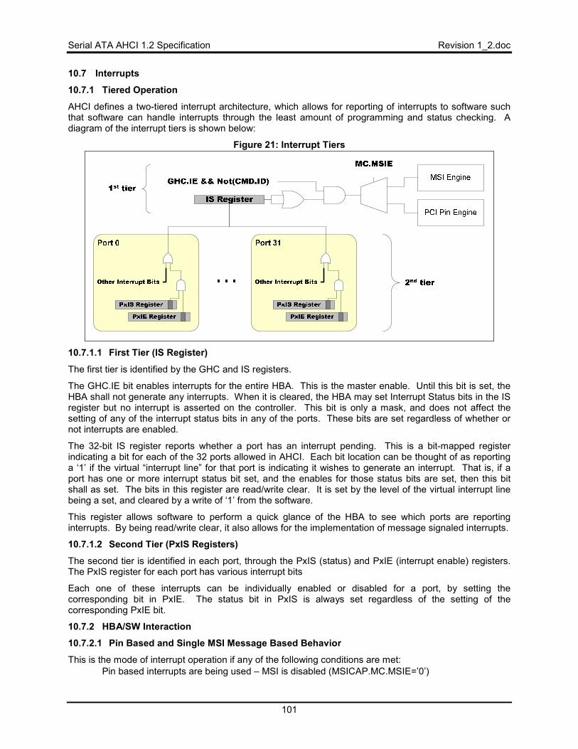
Serial ATA AHCI 1.2 Specification Revision 1_2.doc
101
10.7 Interrupts
10.7.1 Tiered Operation
AHCI defines a two-tiered interrupt architecture, which allows for reporting of interrupts to software such that software can handle interrupts through the least amount of programming and status checking. A diagram of the interrupt tiers is shown below:
Figure 21: Interrupt Tiers
10.7.1.1 First Tier (IS Register)
The first tier is identified by the GHC and IS registers.
The GHC.IE bit enables interrupts for the entire HBA. This is the master enable. Until this bit is set, the HBA shall not generate any interrupts. When it is cleared, the HBA may set Interrupt Status bits in the IS register but no interrupt is asserted on the controller. This bit is only a mask, and does not affect the setting of any of the interrupt status bits in any of the ports. These bits are set regardless of whether or not interrupts are enabled.
The 32-bit IS register reports whether a port has an interrupt pending. This is a bit-mapped register indicating a bit for each of the 32 ports allowed in AHCI. Each bit location can be thought of as reporting a ‘1’ if the virtual “interrupt line” for that port is indicating it wishes to generate an interrupt. That is, if a port has one or more interrupt status bit set, and the enables for those status bits are set, then this bit shall as set. The bits in this register are read/write clear. It is set by the level of the virtual interrupt line being a set, and cleared by a write of ‘1’ from the software.
This register allows software to perform a quick glance of the HBA to see which ports are reporting interrupts. By being read/write clear, it also allows for the implementation of message signaled interrupts.
10.7.1.2 Second Tier (PxIS Registers)
The second tier is identified in each port, through the PxIS (status) and PxIE (interrupt enable) registers. The PxIS register for each port has various interrupt bits
Each one of these interrupts can be individually enabled or disabled for a port, by setting the corresponding bit in PxIE. The status bit in PxIS is always set regardless of the setting of the corresponding PxIE bit.
10.7.2 HBA/SW Interaction
10.7.2.1 Pin Based and Single MSI Message Based Behavior
This is the mode of interrupt operation if any of the following conditions are met: • Pin based interrupts are being used – MSI is disabled (MSICAP.MC.MSIE=’0’)
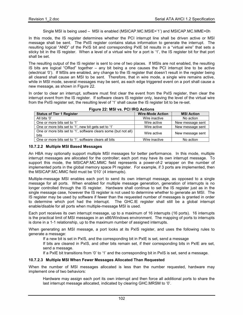
Revision 1_2.doc Serial ATA AHCI 1.2 Specification
102
• Single MSI is being used – MSI is enabled (MSICAP.MC.MSIE=’1’) and MSICAP.MC.MME=0h
In this mode, the IS register determines whether the PCI interrupt line shall be driven active or MSI message shall be sent. The PxIS register contains status information to generate the interrupt. The resulting logical “AND” of the PxIS bit and corresponding PxIE bit results in a “virtual wire” that sets a sticky bit in the IS register. When a level of a virtual wire for a port is ‘1’, the IS register bit for that port shall be set.
The resulting output of the IS register is sent to one of two places. If MSIs are not enabled, the resulting IS bits are logical “ORed” together – any bit being a one causes the PCI interrupt line to be active (electrical ‘0’). If MSIs are enabled, any change to the IS register that doesn’t result in the register being all cleared shall cause an MSI to be sent. Therefore, that in wire mode, a single wire remains active, while in MSI mode, several messages may be sent, as each edge triggered event on a port shall cause a new message, as shown in Figure 22.
In order to clear an interrupt, software must first clear the event from the PxIS register, then clear the interrupt event from the IS register. If software clears IS register only, leaving the level of the virtual wire from the PxIS register set, the resulting level of ‘1’ shall cause the IS register bit to be re-set.
Figure 22: MSI vs. PCI IRQ Actions Status of Tier 1 Register Wire-Mode Action MSI Action All bits ‘0’ Wire inactive No action One or more bits set to ‘1’ Wire active New message sent One or more bits set to ‘1’, new bit gets set to ‘1’ Wire active New message sent One or more bits set to ‘1’, software clears some (but not all) bits Wire active New message sent
One or more bits set to ‘1’, software clears all bits Wire inactive No action
10.7.2.2 Multiple MSI Based Messages
An HBA may optionally support multiple MSI messages for better performance. In this mode, multiple interrupt messages are allocated for the controller; each port may have its own interrupt message. To support this mode, the MSICAP.MC.MMC field represents a power-of-2 wrapper on the number of implemented ports in the global memory space PI register. For example, if 3 ports are implemented, then the MSICAP.MC.MMC field must be ‘010’ (4 interrupts).
Multiple-message MSI enables each port to send its own interrupt message, as opposed to a single message for all ports. When enabled for multiple message generation, generation of interrupts is no longer controlled through the IS register. Hardware shall continue to set the IS register just as in the single message case, however the IS register is not used to determine whether to generate an MSI. The IS register may be used by software if fewer than the requested number of messages is granted in order to determine which port had the interrupt. The GHC.IE register shall still be a global interrupt enable/disable for all ports when multiple-message MSI is used.
Each port receives its own interrupt message, up to a maximum of 16 interrupts (16 ports). 16 interrupts is the practical limit of MSI messages in an x86/Windows environment. The mapping of ports to interrupts is done in a 1-1 relationship, up to the maximum number of assigned interrupts.
When generating an MSI message, a port looks at its PxIS register, and uses the following rules to generate a message:
• If a new bit is set in PxIS, and the corresponding bit in PxIE is set, send a message • If bits are cleared in PxIS, and other bits remain set, if their corresponding bits in PxIE are set,
send a message. • If a PxIE bit transitions from ‘0’ to ‘1’ and the corresponding bit in PxIS is set, send a message.
10.7.2.3 Multiple MSI When Fewer Messages Allocated Than Requested
When the number of MSI messages allocated is less than the number requested, hardware may implement one of two behaviors:
• Hardware may assign each port its own interrupt and then force all additional ports to share the last interrupt message allocated, indicated by clearing GHC.MRSM to ‘0’.
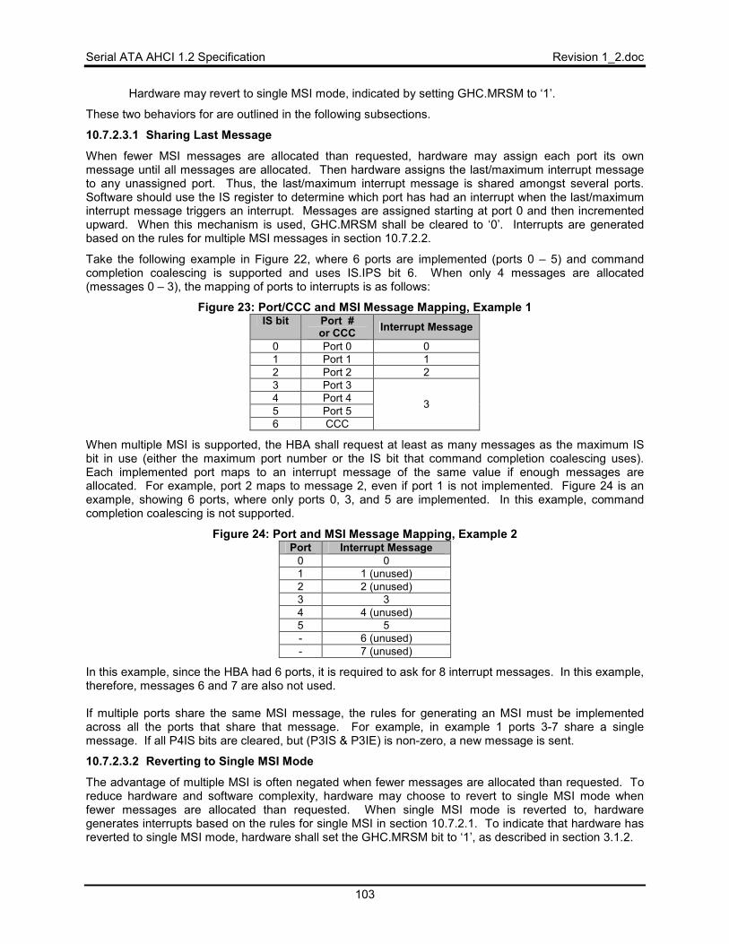
Serial ATA AHCI 1.2 Specification Revision 1_2.doc
103
• Hardware may revert to single MSI mode, indicated by setting GHC.MRSM to ‘1’.
These two behaviors for are outlined in the following subsections.
10.7.2.3.1 Sharing Last Message
When fewer MSI messages are allocated than requested, hardware may assign each port its own message until all messages are allocated. Then hardware assigns the last/maximum interrupt message to any unassigned port. Thus, the last/maximum interrupt message is shared amongst several ports. Software should use the IS register to determine which port has had an interrupt when the last/maximum interrupt message triggers an interrupt. Messages are assigned starting at port 0 and then incremented upward. When this mechanism is used, GHC.MRSM shall be cleared to ‘0’. Interrupts are generated based on the rules for multiple MSI messages in section 10.7.2.2.
Take the following example in Figure 22, where 6 ports are implemented (ports 0 – 5) and command completion coalescing is supported and uses IS.IPS bit 6. When only 4 messages are allocated (messages 0 – 3), the mapping of ports to interrupts is as follows:
Figure 23: Port/CCC and MSI Message Mapping, Example 1 IS bit Port #
or CCC Interrupt Message
0 Port 0 0 1 Port 1 1 2 Port 2 2 3 Port 3 4 Port 4 5 Port 5 6 CCC
3
When multiple MSI is supported, the HBA shall request at least as many messages as the maximum IS bit in use (either the maximum port number or the IS bit that command completion coalescing uses). Each implemented port maps to an interrupt message of the same value if enough messages are allocated. For example, port 2 maps to message 2, even if port 1 is not implemented. Figure 24 is an example, showing 6 ports, where only ports 0, 3, and 5 are implemented. In this example, command completion coalescing is not supported.
Figure 24: Port and MSI Message Mapping, Example 2 Port Interrupt Message
0 01 1 (unused) 2 2 (unused) 3 34 4 (unused) 5 5- 6 (unused) - 7 (unused)
In this example, since the HBA had 6 ports, it is required to ask for 8 interrupt messages. In this example, therefore, messages 6 and 7 are also not used. If multiple ports share the same MSI message, the rules for generating an MSI must be implemented across all the ports that share that message. For example, in example 1 ports 3-7 share a single message. If all P4IS bits are cleared, but (P3IS & P3IE) is non-zero, a new message is sent.
10.7.2.3.2 Reverting to Single MSI Mode
The advantage of multiple MSI is often negated when fewer messages are allocated than requested. To reduce hardware and software complexity, hardware may choose to revert to single MSI mode when fewer messages are allocated than requested. When single MSI mode is reverted to, hardware generates interrupts based on the rules for single MSI in section 10.7.2.1. To indicate that hardware has reverted to single MSI mode, hardware shall set the GHC.MRSM bit to ‘1’, as described in section 3.1.2.
Revision 1_2.doc Serial ATA AHCI 1.2 Specification
104
10.7.3 Disabling Device Interrupts (NIEN Bit in Device Control Register)
The NIEN bit was part of the device control register (legacy I/O addresses 3F6h for primary, 376h for secondary). A legacy HBA must snoop writes to this bit to know whether to mask device interrupts. An AHCI HBA does not snoop this bit. AHCI does not use the NIEN bit; all masking is controlled via the PxIE register. Software should always set the NIEN bit to ‘0’ in all Register FISes transmitted to the device.
10.8 Mechanical Presence Switch Operation
In systems that support a mechanical presence switch, the platform contains a mechanical mechanism that acts as an attention indicator or locking mechanism. When this mechanism changes state (such as a button pressed or switch opened/closed), a line changes state. This line is a level driven signal, not edge-triggered.
HBAs that support mechanical presence switches have the following additional features: • CAP.SMPS shall be set to ‘1’ • PxCMD.MPSP shall be set to ‘1’ for each port that has a mechanical presence switch attached. • An additional input pin per port on the HBA, the level is reflected in PxCMD.MPSS which shows
whether the mechanical presence switch is open or closed.
10.9 Cold Presence Detect Operation
In systems that support cold presence detect, the platform board contains voltage comparator logic, as described in the Serial ATA Revision 2.5 specification, for recognizing attachments, and FET control to supply power to the device.
HBAs that support cold presence-detect have the following additional features: • PxCMD.CPD shall be set to ‘1’ for each port that has cold presence detection capability. • An additional input pin per port on the HBA. • An additional output pin per port on the HBA to be used as FET control for the power rails to the
device. • For each port, PxCMD.POD shall be read/write.
When an HBA that supports cold presence-detect is first powered-up, no power is supplied to the devices. Initialization software checks the status of the ports, and if a device is connected, sets PxCMD.POD to a ‘1’ to supply power to the port.
10.10 Staggered Spin-up Operation
Staggered spin-up is an optional feature in the Serial ATA Revision 2.5 specification. This feature enables an HBA to individually spin-up attached devices. The feature is useful to avoid having a power supply that must handle maximum current draw from all devices at the same time when applying power to the devices. In order for a system to support staggered spin-up, the devices, the HBA, and BIOS/driver must all support staggered spin-up.
In systems that support staggered spin-up, an HBA can individually spin-up devices connected to implemented SATA ports. In systems that do not support staggered spin-up, the HBA spins up all connected SATA devices upon receiving power to the HBA.
Staggered spin-up is only performed when power is applied to the drive. If the drive has been spun-down due to an ATA command (e.g. STANDBY) and the device continues to be powered, the drive will not spin-up again until access to the media is required – the staggered spin-up mechanism is not invoked in this case. Note that when a system transitions to system power management state S3 or greater, the drive will cease having power applied. Since the drive loses power, when the drive is powered back on in the transition back to S0, the drive will undergo another staggered spin-up process.
HBAs that support staggered spin-up shall have the following additional features: • CAP.SSS shall be set. • For each port, PxCMD.SUD shall be read/write.
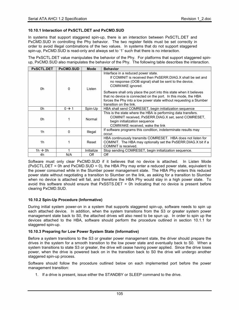
Serial ATA AHCI 1.2 Specification Revision 1_2.doc
105
10.10.1 Interaction of PxSCTL.DET and PxCMD.SUD
In systems that support staggered spin-up, there is an interaction between PxSCTL.DET and PxCMD.SUD in controlling the Phy behavior. The two register fields must be set correctly in order to avoid illegal combinations of the two values. In systems that do not support staggered spin-up, PxCMD.SUD is read-only and always set to ‘1’ such that there is no interaction.
The PxSCTL.DET value manipulates the behavior of the Phy. For platforms that support staggered spin-up, PxCMD.SUD also manipulates the behavior of the Phy. The following table describes the interaction.
PxSCTL.DET PxCMD.SUD Mode Behavior
0h 0 Listen
Interface in a reduced power state. • If COMINIT is received then PxSERR.DIAG.X shall be set and
no response (OOB signal) shall be sent to the device. • COMWAKE ignored.
Software shall only place the port into this state when it believes that no device is connected on the port. In this mode, the HBA forces the Phy into a low power state without requesting a Slumber transition on the link.
0h 0 � 1 Spin-Up HBA shall send COMRESET, begin initialization sequence
0h 1 Normal
This is the state where the HBA is performing data transfers. • COMINIT received, PxSERR.DIAG.X set, send COMRESET,
begin initialization sequence • COMWAKE received, wake the link
1h 0 Illegal If software programs this condition, indeterminate results may occur.
1h 1 Reset HBA continuously transmits COMRESET. HBA does not listen for COMINIT. The HBA may optionally set the PxSERR.DIAG.X bit if a COMINIT is received.
1h � 0h 1 Initialize Stop sending COMRESET, begin initialization sequence. 4h N/A Off Off
Software must only clear PxCMD.SUD if it believes that no device is attached. In Listen Mode (PxSCTL.DET = 0h and PxCMD.SUD = 0), the HBA Phy may enter a reduced power state, equivalent to the power consumed while in the Slumber power management state. The HBA Phy enters this reduced power state without negotiating a transition to Slumber on the link, as asking for a transition to Slumber when no device is attached will fail, and therefore the HBA Phy would stay in a high power state. To avoid this software should ensure that PxSSTS.DET = 0h indicating that no device is present before clearing PxCMD.SUD.
10.10.2 Spin-Up Procedure (Informative)
During initial system power-on in a system that supports staggered spin-up, software needs to spin up each attached device. In addition, when the system transitions from the S3 or greater system power management state back to S0, the attached drives will also need to be spun up. In order to spin up the devices attached to the HBA, software should perform the procedure outlined in section 10.1.1 for staggered spin-up.
10.10.3 Preparing for Low Power System State (Informative)
Before a system transitions to the S3 or greater power management state, the driver should prepare the drives in the system for a smooth transition to the low power state and eventually back to S0. When a system transitions to state S3 or greater, the drive will cease having power applied. Since the drive loses power, when the drive is powered back on in the transition back to S0 the drive will undergo another staggered spin-up process.
Software should follow the procedure outlined below on each implemented port before the power management transition:
1. If a drive is present, issue either the STANDBY or SLEEP command to the drive.
Revision 1_2.doc Serial ATA AHCI 1.2 Specification
106
2. If a drive is present, place the interface into Slumber by setting PxCMD.ICC = 6h.
3. After the interface is no longer in the active power state as specified by PxSSTS.IPM, set PxSCTL.DET = 0h and PxCMD.SUD = 0h to enter listen mode. Note that PxSCTL.DET must be set to 0h before setting PxCMD.SUD to 0h.
This process ensures that staggered spin-up can be used on the system transition back to S0.
10.10.4 When to Enter Listen Mode (Informative)
Listen mode should be entered on a particular port when: • Staggered spin-up is supported on the platform • Interlocked switch is not supported on this port • Cold presence detect is not supported on this port • No device is attached to this port
In this case, listen mode should be entered to save power on the port while still allowing a hot plug insertion event to be detected via PxSERR.DIAG.X. Listen mode should also be entered to save power when a drive is present on a port and the system is about to enter a low power state, refer to section 10.10.3. Listen mode should not be used if mechanical presence switch or cold presence detect is supported on the port. In this instance, the Phy for the port should be placed in the offline mode to save maximum power since any hot plug insertion can be detected using the mechanical presence switch or cold presence detect interrupts.
10.11 Asynchronous Notification
Asynchronous Notification is a feature in Serial ATA Revision 2.5 specification. This feature allows an ATAPI device to send a signal to the host when media is inserted or removed and avoids polling the device for media changes. The signal sent to the host is a Set Device Bits FIS with the ‘I’ (interrupt) and ‘N’ (notification) bits set to ‘1’.
The HBA may support receipt of an asynchronous notification event via the Set Device Bits FIS for a directly attached device. To use asynchronous notification, software should set the PxIS.SDBS bit to enable interrupt notification on a Set Device Bits FIS. When accesses to the ATAPI device are idle, software should place the device in a low power state. When the device has a media change, the device will signal this to the host with a Set Device Bits FIS. In response to receiving a PxIS.SDBS interrupt on an idle port, the host should interrogate the device to determine the cause of the interrupt.
10.11.1 Notifications from Devices Connected to a Port Multiplier
Asynchronous Notification could also be used with a Port Multiplier, particularly when using command-based switching. A few examples of how this mechanism could be used include indicating media has been inserted in an ATAPI device connected to the Port Multiplier or indicating that a hot plug event has occurred on a Port Multiplier port.
In order to utilize asynchronous notification behind a Port Multiplier, the HBA must support the SNotification register that latches the asynchronous notification events from up to 16 targets. The HBA indicates support for the SNotification register by setting CAP.SSNT to ‘1’.
10.11.1.1 SNotification Operation
When a FIS is received by the host controller, the first Dword of the FIS contains a 4 bit Port Multiplier Port (PM Port) field. The PM Port field indicates which port/target behind the Port Multiplier issued the FIS to the host. When a Set Device Bits FIS is received by the host controller and the ‘N’ (Notification) bit is set, the bit position in the SNotification register corresponding to the PM Port field is set. The host will set the PxIS.SDBS bit to “1” if the ‘I’ (Interrupt) bit is set in the Set Device Bits FIS. This will cause an interrupt to be generated if that interrupt is enabled. Note that when a PM is not present, the PM Port field in the Set Device Bits FIS will be 0h causing bit 0 of the SNotification register to be set.
Serial ATA AHCI 1.2 Specification Revision 1_2.doc
107
When using command-based switching, a received FIS is normally discarded if the PM Port field does not match the port currently being accessed. However, to support asynchronous notification from any port behind a Port Multiplier (including the control port), the bit in the SNotification register will be set and an Set Device Bits FIS interrupt will be generated (if enabled) even when the PM Port field of a Set Device Bits FIS does not match the port/target currently being accessed if the ‘N’ (Notification) bit is set in the Set Device Bits FIS. If the ‘N’ bit is set and the PM port does not match the port currently being accessed, then PxIS.IPMS is not set, the FIS is discarded, and PxTFD and PxSACT are not updated based on the contents of the FIS. If the ‘N’ bit is set and the PM port does match the port currently being accessed, the Set Device Bits FIS is processed normally (including posting the FIS, updating PxTFD and PxSACT, etc). If the ‘N’ (Notification) bit is not set in the Set Device Bits FIS, then the Set Device Bits FIS received is handled according to normal processing for the Port Multiplier mode (command-based or FIS-based) that the HBA is operating in.
10.12 Activity LED
An HBA optionally drives an output pin that can be connected to an external LED based upon activity of the various ports in the HBA. The intended use of this LED is for desktop and mobile systems that contain only a single LED to indicate device activity. An HBA indicates support for this pin via CAP.SAL.
The intent of this LED output is to replace the DASP functionality that is provided in parallel ATA systems. The DASP logic in the device would light the LED under the following scenarios:
• During boot, software reset, or device reset: LED would be driven by the slave device on a cable (if present) to indicate slave presence. The LED would remain on until a command was written to the slave device, or 30 seconds, whichever comes first.
• During normal operation, while the BSY bit was set in the task file for ATA commands. It may optionally be on for ATAPI commands (A0h and A1h).
In AHCI, slave devices are not supported – every device is a master. Therefore, the first LED mechanism is not supported by an AHCI HBA. An HBA that supports legacy operation will have to consider this support if it supports master/slave emulation.
To support the second mechanism of LED operation, the HBA shall drive the LED pin active if CAP.SAL is set, and:
• If (PxCI != 0h or PxSACT != 0h) and PxCMD.ATAPI = ‘0’. • If (PxCI != 0h or PxSACT != 0h) and PxCMD.ATAPI = ‘1’ and PxCMD.DLAE = ‘1’,
When PxCI and PxSACT are both cleared to 0h the LED shall be driven off.
10.13 BIST
BIST is entered when software builds a BIST FIS in the command list and sets CTBAz[B]. Once a BIST command is placed into the list, SW is not allowed to build any more commands until it clears PxCMD.ST.
Details of how an HBA operates in the test mode are outside the scope of this specification. A series of vendor specific tests may be performed using vendor specific registers (such as those in the HBA’s PCI configuration space). The details of BIST are not defined in AHCI to allow vendors the freedom of constructing either very elaborate or very light testing schemes.
The test mode is exited when system software clears PxCMD.ST and writes a value of 1h into PxSCTL.DET. Clearing PxCMD.ST shall put the DMA engines into an idle condition, and writing to PxSCTL.DET shall reset the interface.
10.14 Index-Data Pair
Index-Data Pair (IDP) provides host software with a mechanism whereby registers implemented in the AHCI’s memory mapped I/O space (> 1MB) can be read from or written to. On PC based platforms, host software (BIOS, Option ROMs, OSs) written to operate in ‘real-mode’ (8086 mode) is unable to access
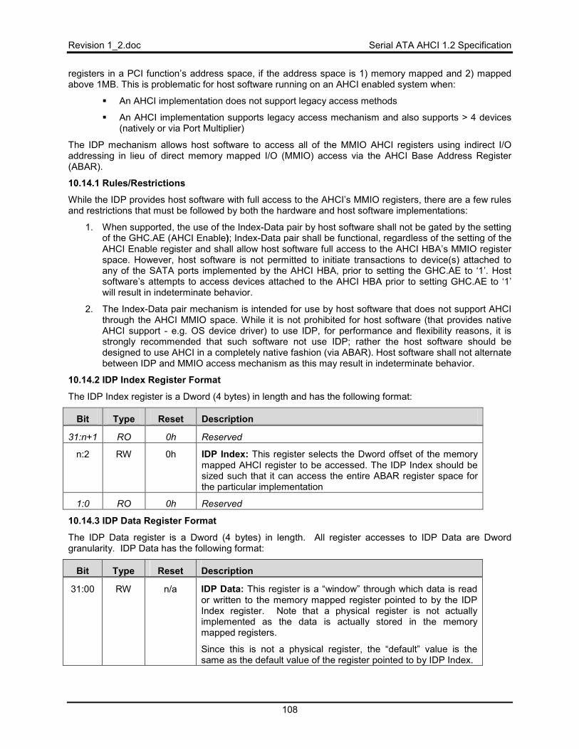
Revision 1_2.doc Serial ATA AHCI 1.2 Specification
108
registers in a PCI function’s address space, if the address space is 1) memory mapped and 2) mapped above 1MB. This is problematic for host software running on an AHCI enabled system when:
� An AHCI implementation does not support legacy access methods
� An AHCI implementation supports legacy access mechanism and also supports > 4 devices (natively or via Port Multiplier)
The IDP mechanism allows host software to access all of the MMIO AHCI registers using indirect I/O addressing in lieu of direct memory mapped I/O (MMIO) access via the AHCI Base Address Register (ABAR).
10.14.1 Rules/Restrictions
While the IDP provides host software with full access to the AHCI’s MMIO registers, there are a few rules and restrictions that must be followed by both the hardware and host software implementations:
1. When supported, the use of the Index-Data pair by host software shall not be gated by the setting of the GHC.AE (AHCI Enable); Index-Data pair shall be functional, regardless of the setting of the AHCI Enable register and shall allow host software full access to the AHCI HBA’s MMIO register space. However, host software is not permitted to initiate transactions to device(s) attached to any of the SATA ports implemented by the AHCI HBA, prior to setting the GHC.AE to ‘1’. Host software’s attempts to access devices attached to the AHCI HBA prior to setting GHC.AE to ‘1’ will result in indeterminate behavior.
2. The Index-Data pair mechanism is intended for use by host software that does not support AHCI through the AHCI MMIO space. While it is not prohibited for host software (that provides native AHCI support - e.g. OS device driver) to use IDP, for performance and flexibility reasons, it is strongly recommended that such software not use IDP; rather the host software should be designed to use AHCI in a completely native fashion (via ABAR). Host software shall not alternate between IDP and MMIO access mechanism as this may result in indeterminate behavior.
10.14.2 IDP Index Register Format
The IDP Index register is a Dword (4 bytes) in length and has the following format:
Bit Type Reset Description
31:n+1 RO 0h Reserved
n:2 RW 0h IDP Index: This register selects the Dword offset of the memory mapped AHCI register to be accessed. The IDP Index should be sized such that it can access the entire ABAR register space for the particular implementation
1:0 RO 0h Reserved
10.14.3 IDP Data Register Format
The IDP Data register is a Dword (4 bytes) in length. All register accesses to IDP Data are Dword granularity. IDP Data has the following format:
Bit Type Reset Description
31:00 RW n/a IDP Data: This register is a “window” through which data is read or written to the memory mapped register pointed to by the IDP Index register. Note that a physical register is not actually implemented as the data is actually stored in the memory mapped registers.
Since this is not a physical register, the “default” value is the same as the default value of the register pointed to by IDP Index.
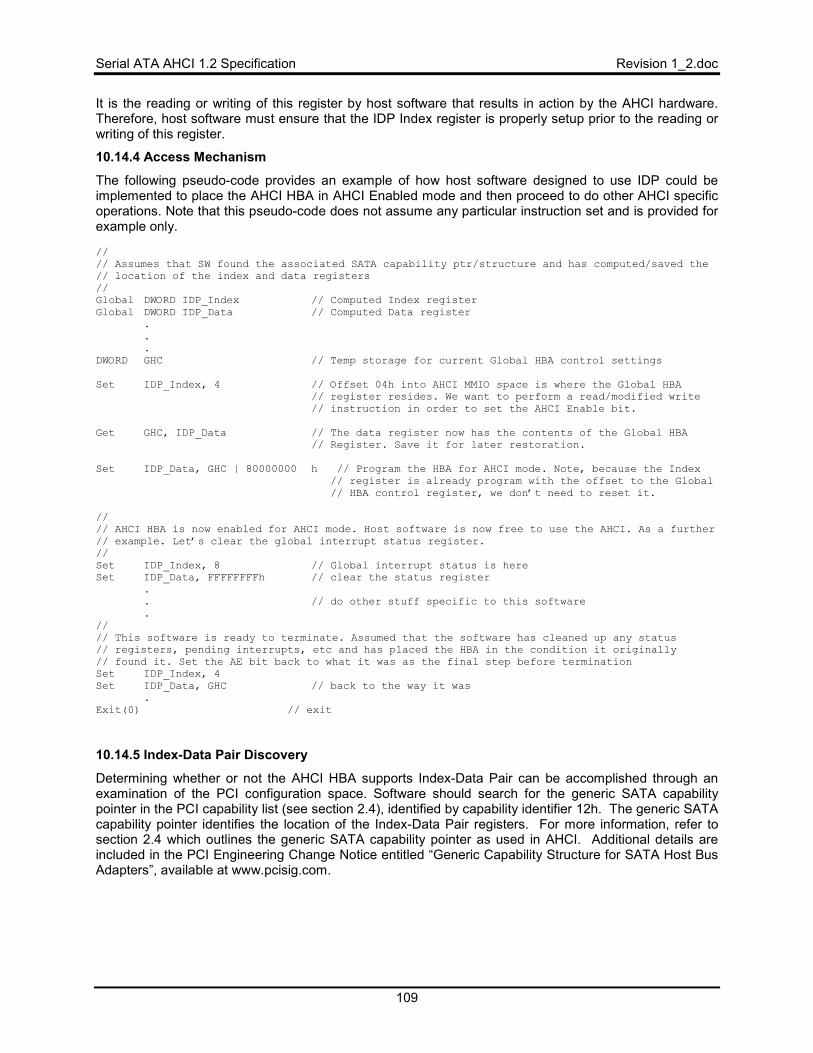
Serial ATA AHCI 1.2 Specification Revision 1_2.doc
109
It is the reading or writing of this register by host software that results in action by the AHCI hardware. Therefore, host software must ensure that the IDP Index register is properly setup prior to the reading or writing of this register.
10.14.4 Access Mechanism
The following pseudo-code provides an example of how host software designed to use IDP could be implemented to place the AHCI HBA in AHCI Enabled mode and then proceed to do other AHCI specific operations. Note that this pseudo-code does not assume any particular instruction set and is provided for example only. // // Assumes that SW found the associated SATA capability ptr/structure and has computed/saved the // location of the index and data registers // Global DWORD IDP_Index // Computed Index register Global DWORD IDP_Data // Computed Data register .
.
.DWORD GHC // Temp storage for current Global HBA control settings Set IDP_Index, 4 // Offset 04h into AHCI MMIO space is where the Global HBA // register resides. We want to perform a read/modified write // instruction in order to set the AHCI Enable bit. Get GHC, IDP_Data // The data register now has the contents of the Global HBA // Register. Save it for later restoration. Set IDP_Data, GHC | 80000000 h // Program the HBA for AHCI mode. Note, because the Index // register is already program with the offset to the Global // HBA control register, we don’t need to reset it. // // AHCI HBA is now enabled for AHCI mode. Host software is now free to use the AHCI. As a further // example. Let’s clear the global interrupt status register. // Set IDP_Index, 8 // Global interrupt status is here Set IDP_Data, FFFFFFFFh // clear the status register .
. // do other stuff specific to this software .// // This software is ready to terminate. Assumed that the software has cleaned up any status // registers, pending interrupts, etc and has placed the HBA in the condition it originally // found it. Set the AE bit back to what it was as the final step before termination Set IDP_Index, 4 Set IDP_Data, GHC // back to the way it was .Exit(0) // exit
10.14.5 Index-Data Pair Discovery
Determining whether or not the AHCI HBA supports Index-Data Pair can be accomplished through an examination of the PCI configuration space. Software should search for the generic SATA capability pointer in the PCI capability list (see section 2.4), identified by capability identifier 12h. The generic SATA capability pointer identifies the location of the Index-Data Pair registers. For more information, refer to section 2.4 which outlines the generic SATA capability pointer as used in AHCI. Additional details are included in the PCI Engineering Change Notice entitled “Generic Capability Structure for SATA Host Bus Adapters”, available at www.pcisig.com.
Revision 1_2.doc Serial ATA AHCI 1.2 Specification
110
11 Command Completion Coalescing Command Completion Coalescing (CCC) is a feature designed to reduce the interrupt and command completion overhead in a heavily loaded system. The feature enables the number of interrupts taken per completion to be reduced significantly, while ensuring a minimum quality of service for command completions. When a software specified number of commands have completed or a software specified timeout has expired, an interrupt is generated by hardware to allow software to process completed commands. This feature applies to all ports selected to be in the command completion coalescing set by software via the CCC_PORTS register.
11.1 Command Completion Definition
A command completion has occurred when either of the following occurs on a port selected for command coalescing:
• (PxCI[x] transitions from ‘1’ to ‘0’) AND (PxSACT[x] = ‘0’)
• PxSACT[x] transitions from ‘1’ to ‘0’
When a command completes the internal HBA variable, hCccComplete, is incremented by one. If multiple bits transition at the same time and meet one of the preceding criteria, hCccComplete is incremented once for each bit that satisfies the criteria.
11.2 Timer Definition
An HBA that implements the command completion coalescing shall have an internal timer, hCccTimer, that is decremented while there are commands outstanding on ports selected for command coalescing. Commands are outstanding when for any port selected for command coalescing, the value of PxCI or PxSACT is non-zero. hCccTimer is decremented by 1h every 1 millisecond (the resolution of the software specified timeout value).
11.3 Selected Ports
A subset of the implemented ports, as defined by the Ports Implemented (PI) register, may be specified for use with the command completion coalescing feature. The subset is defined by the bit-significant register CCC_PORTS. If a bit is set to ‘1’ in CCC_PORTS and the same bit is also set to ‘1’ in PI, then that port is selected to be included in command completion coalescing.
The CCC_PORTS value may be updated at any time by software. However, if there are outstanding commands on any ports at the time CCC_PORTS is updated, the HBA may not immediately adjust to ports that have just been selected or deselected. For example, if a command is in progress on a particular port and the command is about to complete near the same moment that CCC_PORTS is updated to newly select this port, the HBA may not increment hCccComplete. An updated CCC_PORTS value is guaranteed to be in effect within 1 millisecond of the write to the CCC_PORTS register.
If a port is currently selected for command completion coalescing and an error occurs that requires PxCMD.ST to be cleared to ‘0’, software shall remove the affected port from the selected ports for command completion coalescing prior to clearing PxCMD.ST to ‘0’.
11.4 Interrupt Definition
The command coalescing completion interrupt, called the ‘CCC interrupt’, is generated on any of the following conditions:
• hCccComplete is greater than or equal to the value specified by software in CCC_CTL.CC and CCC_CTL.CC != 0.
• hCccTimer is decremented to 0h. (The interrupt is generated on the decrement to 0h, not the decrement from 0h to -1.)
• hCccComplete is incremented and there are no more commands outstanding on the selected ports for command completion coalescing and CCC_CTL.CC != 0.
Serial ATA AHCI 1.2 Specification Revision 1_2.doc
111
When the CCC interrupt is generated, hCccComplete is reset to 0h and hCccTimer is reset to the software specified timeout value in CCC_CTL.TV. If commands complete on the same cycle that hCccComplete is to be reset to 0h, the final value of hCccComplete shall be 0h after that cycle. These additional completions are “aggregated” into the current CCC interrupt that is being generated.The CCC interrupt utilizes the Interrupt Status (IS) register bit specified in CCC_CTL.INT. The CCC interrupt shall also use the MSI vector that corresponds to CCC_CTL.INT. The CCC interrupt corresponds to the interrupt for an unimplemented port on the controller.
11.5 Enable and Disable Behavior
The CCC feature is only in use when CCC_CTL.EN is set to ‘1’. If CCC_CTL.EN is set to ‘0’, no CCC interrupts shall be generated.
On transition of CCC_CTL.EN from ‘0’ to ‘1’, the following shall occur:
• HBA uses the Timeout Value specified in the CCC_CTL.TV field • HBA uses the Command Completions value specified in the CCC_CTL.CC field • hCccTimer is reset to CC_CTL.TV • hCccComplete is reset to 0h
Software shall not modify the values in CCC_CTL.TV nor CCC_CTL.CC while CCC_CTL.EN is set to ‘1’. Writing these values while command completion coalescing is enabled will result in indeterminate behavior.
11.6 Software Behavior
11.6.1 Initialization
To initialize use of the command completion coalescing feature for a set of ports, software needs to perform several steps.
• Software should turn off per port interrupts for the D2H Register FIS and the Set Device Bits FIS (clear PxIE.DHRE and PxIE.SDBE to ‘0’) for each port that will be part of command completion coalescing.
• Software should turn on per port interrupts for hot plug and error events. These events should be handled on a per port basis.
• Software should ensure that CCC_CTL.EN is cleared to ‘0’. • Software should set CCC_PORTS to the desired value based on which ports should be part of
the command completion coalescing set. Note that software shall only set a bit in the CCC_PORTS register if the corresponding bit is set in the Ports Implemented (PI) register.
• Software should set CCC_CTL.TV and CCC_CTL.CC to the desired values. • Software should enable command completion coalescing by setting CCC_CTL.EN to ‘1’.
After enabling command completion coalescing, software should check if any commands have completed on any port while performing the initialization. Software can do this by checking the PxCI (non-queued commands) or PxSACT (native queued commands) register for each port whose corresponding bit is set to ‘1’ in CCC_PORTS.
11.6.2 Errors and Hot Plug Events
Note that error and hot plug events are handled on a per port basis, so the corresponding per port enable (PxIE) bits are set to ‘1’. When an error or hot plug event occurs, software should remove that port from the command completion coalescing set by updated CCC_PORTS. This change will take effect within 1 millisecond. Then software should service the error or hot plug event. After the port is again functional, software may add the port to the command completion coalescing set by updating CCC_PORTS. CCC_CTL.EN may be set to ‘1’ when a port is added to or removed from the command completion coalescing set.
Revision 1_2.doc Serial ATA AHCI 1.2 Specification
112
11.6.3 CCC Interrupt Handling
Upon detecting that a CCC interrupt has occurred, software should perform the following steps in order.
• Software should clear the CCC interrupt by writing a ‘1’ to bit location IS.IPS[CCC_CTL.INT]. Note that this step is not required if multiple MSI messaging is in use.
• Software should query the PxCI (for non-queuing commands) and PxSACT (for native queued commands) registers to determine the commands that have been completed.
• Software should complete commands finished commands to the OS that were identified in the previous step.
11.6.4 Updating Timeout Value or Number of Command Completions
Software during the course of operation may choose to update the timeout value or the number of command completions required before causing the CCC interrupt based on implementation specific algorithms. To update these values, software should perform the following procedure:
• Software should clear CCC_CTL.EN to ‘0’ • Software should update CCC_CTL.TV (timeout value) and CCC_CTL.CC (number of command
completions) as desired • Software should set CCC_CTL.EN to ‘1’
Software shall not modify the values in CCC_CTL.TV nor CCC_CTL.CC while CCC_CTL.EN is set to ‘1’. Writing these values while command completion coalescing is enabled will result in indeterminate behavior.
While command completion coalescing was disabled, additional commands may have completed on those ports that are part of the command completion coalescing set. After re-enabling command completion coalescing, software should check if any commands have completed on any port while performing the initialization. Software can do this by checking the PxCI (non-queued commands) or PxSACT (native queued commands) register for each port whose corresponding bit is set to ‘1’ in CCC_PORTS.
11.7 Example (Informative)
This section describes an example scenario of commands completing on multiple ports when command completion coalescing is used. This example is meant to illustrate core concepts of command completion coalescing.
Software selects ports 2, 4, and 5 to be in the command completion set by writing CCC_PORTS = 00000034h. The CCC_CTL.TV value is set by software to 5000 to ensure that a CCC interrupt is generated at least every 5 seconds to ensure that completed commands are not timed out at a higher level by the OS. The CCC_CTL.CC value is set to 5 by software to cause a CCC interrupt after 5 total commands have completed among ports 2, 4, and 5. Software has selected the value of 5 based on the current amount of traffic being seen on ports 2, 4, and 5 and based on quality of service requirements. After setting the CCC_CTL.TV and CCC_CTL.CC values appropriately, software enables CCC by setting CCC_CTL.EN to ‘1’.
Software receives three commands to issue for port 2. These commands are issued in a non-queued fashion and the resulting P2CI value is 00000015h (commands are issued in slots 0, 2, and 4) and P2SACT is 0h. Software receives two commands to issue for port 5. These commands are issued as NCQ commands and the resulting P5SACT value is 00010100h (commands are issued with tags 8 and 16). At this point, hCccTimer has decremented to 4700 (300 milliseconds have elapsed since CCC_CTL.EN was set to ‘1’) and hCccComplete is still 0h.
The drive attached to port 2 completes command 0 and P2CI is updated to be 00000014h. When bit 0 of P2CI transitions from ‘1’ to ‘0’ the hCccComplete variable will be incremented to 1h since P2SACT bit 0 is also cleared to ‘0’. Next the drive attached to port 5 completes both commands and P5SACT is updated to be 0h. When bits 8 and 16 transition from ‘1’ to ‘0’, hCccComplete will be incremented by 2 to a value of 3h. The hCccComplete variable is incremented once for each command that completes; note that when PxSACT bits transition from ‘1’ to ‘0’ there is no qualification on the values of the PxCI register for
Serial ATA AHCI 1.2 Specification Revision 1_2.doc
113
incrementing hCccComplete. At this point, hCccTimer has decremented to 4200 and hCccComplete is 3h.
Software receives three more commands for port 5. These commands are issued as NCQ commands and the resulting P5SACT value is 00700000h (commands are issued with tags 20, 21, and 22). At this point, no more commands have been completed so hCccComplete remains set to 3h while hCccTimer has continued to decrement to 4000.
The drive attached to port 5 completes the command with tag 22. P5SACT is updated to be 00300000h. When bit 22 transitions from ‘1’ to ‘0’, hCccComplete will be incremented by 1 to a value of 4h.
The drive attached to port 2 completes the command in slot 2. P2CI is updated to be 00000010h. When bit 2 transitions from ‘1’ to ‘0’, hCccComplete will be incremented by 1 to a value of 5h since P2SACT bit 2 is also cleared to ‘0’. At his point, hCccTimer has decremented to 3500 and hCccComplete is 5h.
When hCccComplete is incremented to 5h (or greater if multiple commands had completed in the same cycle), the hardware will recognize that the number of commands completed has reached the CCC_CTL.CC threshold. Hardware will then clear hCccComplete to 0h, set hCccTimer to CCC_CTL.TV, and then set IS.IPS[CCC_CTL.INT] to ‘1’. If interrupts are enabled (GHC.IE = ‘1’), the HBA will then generate an interrupt to software.
After this interrupt is generated to software, the process continues and hCccComplete will start incrementing again based on completions, while hCccTimer will continue to decrement as time elapses.
Revision 1_2.doc Serial ATA AHCI 1.2 Specification
114
12 Enclosure Management Enclosure management is a mechanism by which the storage driver can monitor and control auxiliary services in a drive enclosure. The most common task is controlling LEDs that show per drive status information. LEDs per drive could include device activity, fault (to indicate a failure), and locate (to show an operator the bay to remove/insert a drive from/into). Note that device activity indications may be provided by the device itself. Other examples of enclosure management features include: power supply control and monitoring, temperature monitoring, and presence detection.
There are three common enclosure management protocols in use: SAF-TE, SES-2 and SGPIO. References to these specifications are in section 1.9. These protocols are typically used between the host controller (or Port Multiplier) and an enclosure processor that controls/monitors the sensors/LEDs within the enclosure.
To use the SAF-TE or SES-2 protocols, the HBA must communicate with a storage enclosure processor (SEP) that supports the desired protocol. The physical bus that attaches the HBA to the SEP is I2C; note that this requires additional pins to be added to the HBA. The IPMI protocol is used over I2C to communicate with the SEP. The Serial ATA Revision 2.5 specification contains details on how SAF-TE and SES-2 packets are exchanged with a SEP.
To use the SGPIO protocol, the HBA communicates with an SGPIO target. The 4 pin bus that attaches the HBA to the SGPIO target is defined in the SGPIO specification.
12.1 Mechanism
Enclosure management involves sending messages that control features of the enclosure or receiving messages that provide status for the enclosure. The messages for this function are stored after the normal registers in the AHCI BAR, at an implementation specific offset from the beginning of the AHCI BAR as specified by the EM_LOC global register.
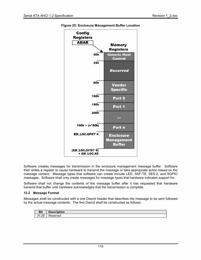
Serial ATA AHCI 1.2 Specification Revision 1_2.doc
115
Figure 25: Enclosure Management Buffer Location
Software creates messages for transmission in the enclosure management message buffer. Software then writes a register to cause hardware to transmit the message or take appropriate action based on the message content. Message types that software can create include LED, SAF-TE, SES-2, and SGPIO messages. Software shall only create messages for message types that hardware indicates support for.
Software shall not change the contents of the message buffer after it has requested that hardware transmit that buffer until hardware acknowledges that the transmission is complete.
12.2 Message Format
Messages shall be constructed with a one Dword header that describes the message to be sent followed by the actual message contents. The first Dword shall be constructed as follows:
Bit Description
31:28 Reserved
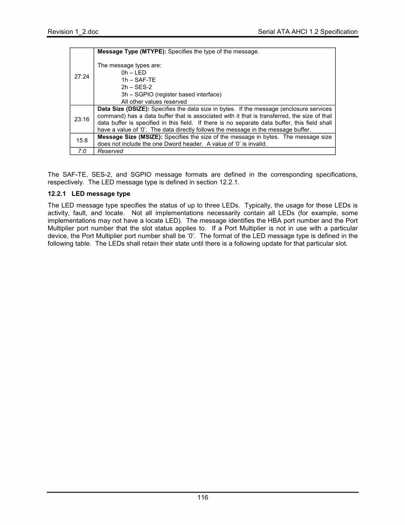
Revision 1_2.doc Serial ATA AHCI 1.2 Specification
116
27:24
Message Type (MTYPE): Specifies the type of the message. The message types are:
• 0h – LED • 1h – SAF-TE • 2h – SES-2 • 3h – SGPIO (register based interface) • All other values reserved
23:16
Data Size (DSIZE): Specifies the data size in bytes. If the message (enclosure services command) has a data buffer that is associated with it that is transferred, the size of that data buffer is specified in this field. If there is no separate data buffer, this field shall have a value of ‘0’. The data directly follows the message in the message buffer.
15:8 Message Size (MSIZE): Specifies the size of the message in bytes. The message size does not include the one Dword header. A value of ‘0’ is invalid.
7:0 Reserved
The SAF-TE, SES-2, and SGPIO message formats are defined in the corresponding specifications, respectively. The LED message type is defined in section 12.2.1.
12.2.1 LED message type
The LED message type specifies the status of up to three LEDs. Typically, the usage for these LEDs is activity, fault, and locate. Not all implementations necessarily contain all LEDs (for example, some implementations may not have a locate LED). The message identifies the HBA port number and the Port Multiplier port number that the slot status applies to. If a Port Multiplier is not in use with a particular device, the Port Multiplier port number shall be ‘0’. The format of the LED message type is defined in the following table. The LEDs shall retain their state until there is a following update for that particular slot.
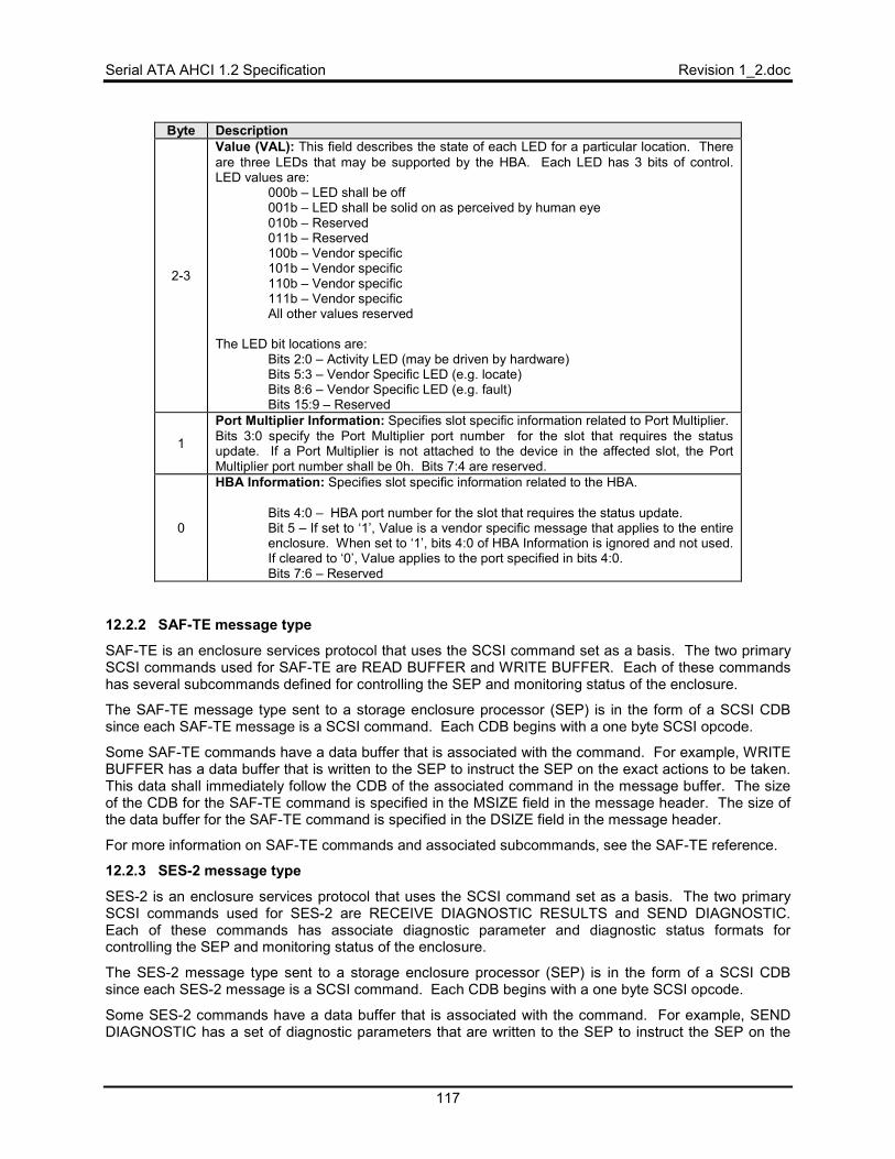
Serial ATA AHCI 1.2 Specification Revision 1_2.doc
117
Byte Description
2-3
Value (VAL): This field describes the state of each LED for a particular location. There are three LEDs that may be supported by the HBA. Each LED has 3 bits of control. LED values are:
000b – LED shall be off 001b – LED shall be solid on as perceived by human eye 010b – Reserved 011b – Reserved 100b – Vendor specific 101b – Vendor specific 110b – Vendor specific 111b – Vendor specific All other values reserved
The LED bit locations are:
Bits 2:0 – Activity LED (may be driven by hardware) Bits 5:3 – Vendor Specific LED (e.g. locate) Bits 8:6 – Vendor Specific LED (e.g. fault) Bits 15:9 – Reserved
1
Port Multiplier Information: Specifies slot specific information related to Port Multiplier. Bits 3:0 specify the Port Multiplier port number for the slot that requires the status update. If a Port Multiplier is not attached to the device in the affected slot, the Port Multiplier port number shall be 0h. Bits 7:4 are reserved.
0
HBA Information: Specifies slot specific information related to the HBA.
Bits 4:0 – HBA port number for the slot that requires the status update. Bit 5 – If set to ‘1’, Value is a vendor specific message that applies to the entire enclosure. When set to ‘1’, bits 4:0 of HBA Information is ignored and not used. If cleared to ‘0’, Value applies to the port specified in bits 4:0. Bits 7:6 – Reserved
12.2.2 SAF-TE message type
SAF-TE is an enclosure services protocol that uses the SCSI command set as a basis. The two primary SCSI commands used for SAF-TE are READ BUFFER and WRITE BUFFER. Each of these commands has several subcommands defined for controlling the SEP and monitoring status of the enclosure.
The SAF-TE message type sent to a storage enclosure processor (SEP) is in the form of a SCSI CDB since each SAF-TE message is a SCSI command. Each CDB begins with a one byte SCSI opcode.
Some SAF-TE commands have a data buffer that is associated with the command. For example, WRITE BUFFER has a data buffer that is written to the SEP to instruct the SEP on the exact actions to be taken. This data shall immediately follow the CDB of the associated command in the message buffer. The size of the CDB for the SAF-TE command is specified in the MSIZE field in the message header. The size of the data buffer for the SAF-TE command is specified in the DSIZE field in the message header.
For more information on SAF-TE commands and associated subcommands, see the SAF-TE reference.
12.2.3 SES-2 message type
SES-2 is an enclosure services protocol that uses the SCSI command set as a basis. The two primary SCSI commands used for SES-2 are RECEIVE DIAGNOSTIC RESULTS and SEND DIAGNOSTIC. Each of these commands has associate diagnostic parameter and diagnostic status formats for controlling the SEP and monitoring status of the enclosure.
The SES-2 message type sent to a storage enclosure processor (SEP) is in the form of a SCSI CDB since each SES-2 message is a SCSI command. Each CDB begins with a one byte SCSI opcode.
Some SES-2 commands have a data buffer that is associated with the command. For example, SEND DIAGNOSTIC has a set of diagnostic parameters that are written to the SEP to instruct the SEP on the

Revision 1_2.doc Serial ATA AHCI 1.2 Specification
118
exact actions to be taken. This data shall immediately follow the CDB of the associated command in the message buffer. The size of the CDB for the SES-2 command is specified in the MSIZE field in the message header. The size of the data buffer for the SES-2 command is specified in the DSIZE field in the message header.
For more information on SES-2 commands and diagnostic parameters/formats, see the SES-2 reference.
Serial ATA AHCI 1.2 Specification Revision 1_2.doc
119
13 Informative Appendix 13.1 Port Selector Support
A Port Selector may be attached to an HBA port. To control the Port Selector with protocol-based port selection, software should issue COMRESET bursts at the appropriate intervals by using the PxSCTL register appropriately. Controlling the Port Selector with side-band port selection is beyond the scope of this specification.
13.2 Legacy ATAPI Device Seek Complete Behavior
DSC (Device Seek Complete) was introduced in the ATA/3 specification and defined as bit 4 of the Status register. ATAPI devices began using this bit soon after. In the ATA/4 specification the DSC bit was made command specific and by the ATA/5 specification DSC was no longer used as part of any ATA commands.
The intention of the DSC bit was to allow for a device to drop BSY and DRQ and indicate command completion some time later by setting the DSC bit. Dropping BSY and DRQ allowed the bus to be free and commands could be issued to the other device (in a master/slave configuration). With the introduction of SATA (with a dedicated device/host connection) there is no benefit to the DSC behavior.
Serial ATA is based on the ATA/5 specification. Thus, Serial ATA has no concept of DSC. By extension, as the programming interface for Serial ATA, AHCI has no concept of DSC as a mechanism for completing an ATAPI command. In addition, AHCI is designed to be command agnostic and require no snooping of actual ATA opcodes for extensibility. AHCI hardware has no specific knowledge of DSC or commands that make use of this bit. AHCI assumes command completion when BSY and DRQ (no errors) are lowered by the device via a Device-to-Host Register FIS. Under this condition an AHCI controller will de-assert the PxCI bit associated with the command and proceed to process the next command slot.
Older parallel ATAPI devices may continue to use the DSC bit as it was originally intended and may be used in conjunction with PATA-to-SATA bridges. Observed behavior with these devices for some commands may include clearing the BSY and DRQ bits immediately and then sometime later issuing a Set Device Bits FIS to update DSC to ‘1’ in order to indicate command completion. In this case the AHCI controller will indicate completion when BSY and DRQ are lowered, update PxCI, and move on to the next command (possibly before the device actually completed the initial command).
In order to avoid issues with legacy based ATAPI devices that use the DSC bit in this manner, software may be modified to poll on DSC for completion of the impacted commands. A bridged ATAPI device may be identified by checking that Word 76 in IDENTIFY PACKET DEVICE is 0000h or FFFFh.
The following is a list of MMC commands that may use DSC as described above: – 2Bh - Seek (10) – 45h - Play Audio (10) – 47h - Play Audio MSF – A5h - Play Audio (12) – BAh – Scan – BCh - Play CD