Embed Size (px)
Citation preview

BIO COMPRESSION SYSTEMS 120 West Commercial Avenue
Moonachie, New Jersey 07074
Phone: 800-888-0908 Fax: 201-939-4503
Web site: www.biocompression.com
E-mail: [email protected]
SEQUENTIALSEQUENTIAL
CIRCULATORCIRCULATOR
MODEL 3008
Congratulations on the purchasing of your
BIO COMPRESSION SYSTEMS
MODEL # SC-3008
Sequential 8 Circulator System
The durable, high quality material used in the manufacturing of
this product will ensure you long lasting performance.
On rare incidences when problems occur, you can feel confident
that your pump and garment are backed by the best warranty and
customer service in the industry! By simply dialing our toll free
number for customer service
800-888-0908
warranty repairs or adjustments will be
performed in a timely manner with minimal
inconvenience to you
Should a warranty repair require an extended length of time, if
available, a pump from our “loaner inventory” will be made avail-
able to you, so as to prevent any interruption in your treatment
schedule.
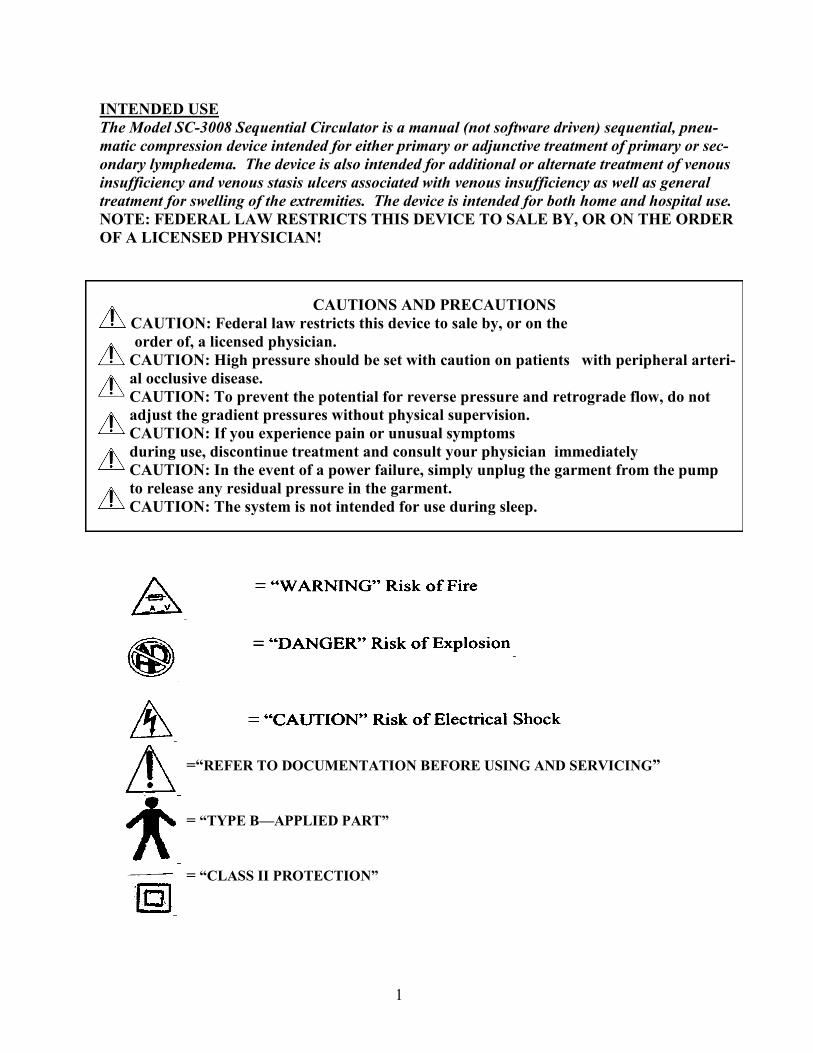
INTENDED USE
The Model SC-3008 Sequential Circulator is a manual (not software driven) sequential, pneu-
matic compression device intended for either primary or adjunctive treatment of primary or sec-
ondary lymphedema. The device is also intended for additional or alternate treatment of venous
insufficiency and venous stasis ulcers associated with venous insufficiency as well as general
treatment for swelling of the extremities. The device is intended for both home and hospital use.
NOTE: FEDERAL LAW RESTRICTS THIS DEVICE TO SALE BY, OR ON THE ORDER
OF A LICENSED PHYSICIAN!
CAUTIONS AND PRECAUTIONS
CAUTION: Federal law restricts this device to sale by, or on the
order of, a licensed physician.
CAUTION: High pressure should be set with caution on patients with peripheral arteri-
al occlusive disease.
CAUTION: To prevent the potential for reverse pressure and retrograde flow, do not
adjust the gradient pressures without physical supervision.
CAUTION: If you experience pain or unusual symptoms
during use, discontinue treatment and consult your physician immediately
CAUTION: In the event of a power failure, simply unplug the garment from the pump
to release any residual pressure in the garment.
CAUTION: The system is not intended for use during sleep.
=“REFER TO DOCUMENTATION BEFORE USING AND SERVICING”
= “TYPE B—APPLIED PART”
= “CLASS II PROTECTION”
1
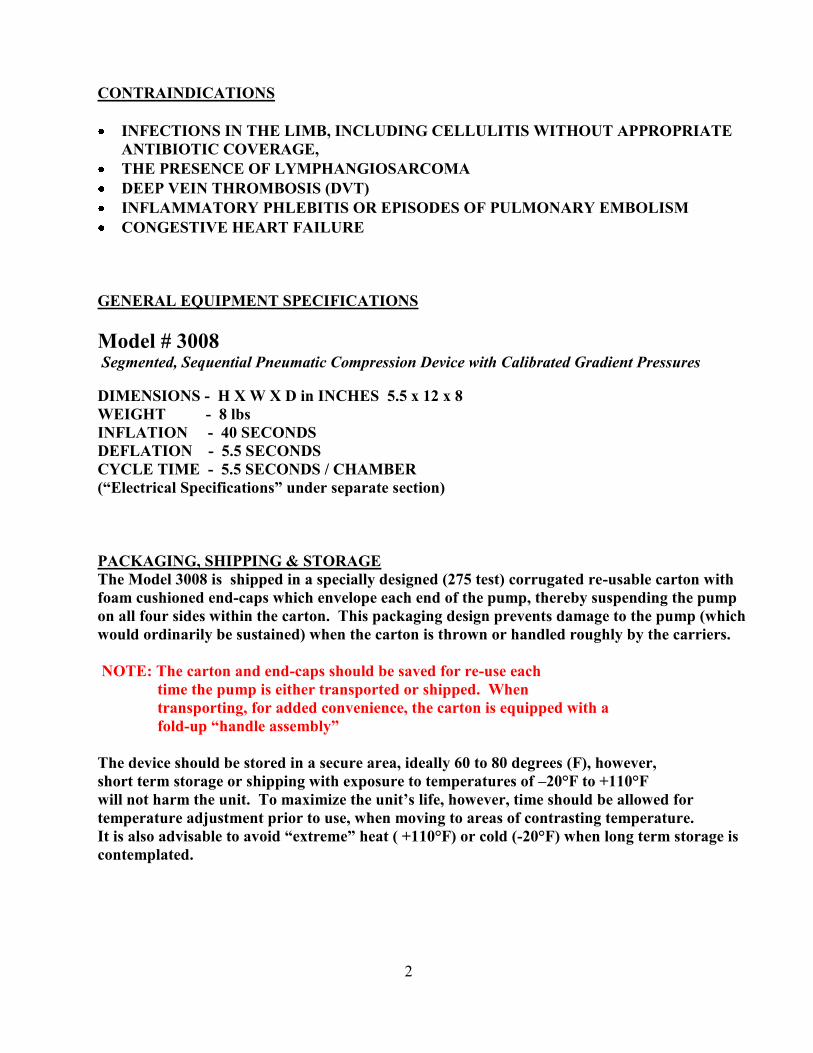
CONTRAINDICATIONS
INFECTIONS IN THE LIMB, INCLUDING CELLULITIS WITHOUT APPROPRIATE
ANTIBIOTIC COVERAGE,
THE PRESENCE OF LYMPHANGIOSARCOMA
DEEP VEIN THROMBOSIS (DVT)
INFLAMMATORY PHLEBITIS OR EPISODES OF PULMONARY EMBOLISM
CONGESTIVE HEART FAILURE
GENERAL EQUIPMENT SPECIFICATIONS
Model # 3008 Segmented, Sequential Pneumatic Compression Device with Calibrated Gradient Pressures
DIMENSIONS - H X W X D in INCHES 5.5 x 12 x 8
WEIGHT - 8 lbs
INFLATION - 40 SECONDS
DEFLATION - 5.5 SECONDS
CYCLE TIME - 5.5 SECONDS / CHAMBER
(“Electrical Specifications” under separate section)
PACKAGING, SHIPPING & STORAGE
The Model 3008 is shipped in a specially designed (275 test) corrugated re-usable carton with
foam cushioned end-caps which envelope each end of the pump, thereby suspending the pump
on all four sides within the carton. This packaging design prevents damage to the pump (which
would ordinarily be sustained) when the carton is thrown or handled roughly by the carriers.
NOTE: The carton and end-caps should be saved for re-use each
time the pump is either transported or shipped. When
transporting, for added convenience, the carton is equipped with a
fold-up “handle assembly”
The device should be stored in a secure area, ideally 60 to 80 degrees (F), however,
short term storage or shipping with exposure to temperatures of –20°F to +110°F
will not harm the unit. To maximize the unit’s life, however, time should be allowed for
temperature adjustment prior to use, when moving to areas of contrasting temperature.
It is also advisable to avoid “extreme” heat ( +110°F) or cold (-20°F) when long term storage is
contemplated.
2
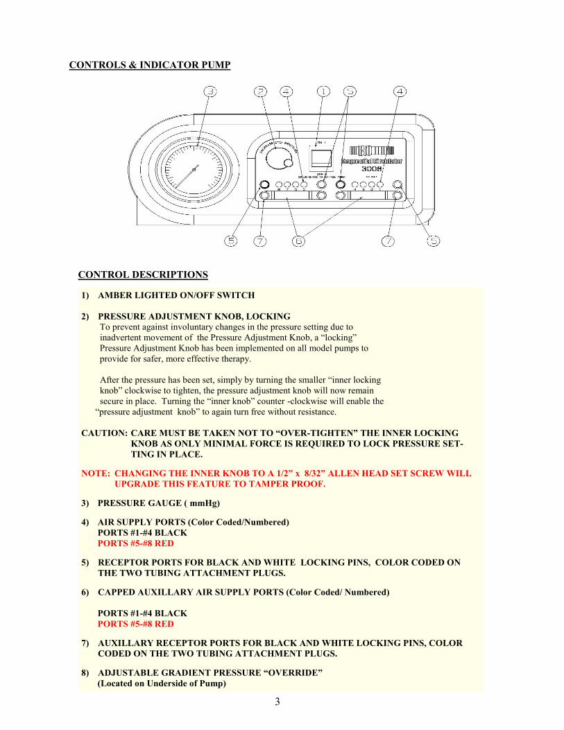
CONTROLS & INDICATOR PUMP
CONTROL DESCRIPTIONS
1) AMBER LIGHTED ON/OFF SWITCH
2) PRESSURE ADJUSTMENT KNOB, LOCKING
To prevent against involuntary changes in the pressure setting due to
inadvertent movement of the Pressure Adjustment Knob, a “locking”
Pressure Adjustment Knob has been implemented on all model pumps to
provide for safer, more effective therapy.
After the pressure has been set, simply by turning the smaller “inner locking
knob” clockwise to tighten, the pressure adjustment knob will now remain
secure in place. Turning the “inner knob” counter -clockwise will enable the
“pressure adjustment knob” to again turn free without resistance.
CAUTION: CARE MUST BE TAKEN NOT TO “OVER-TIGHTEN” THE INNER LOCKING
KNOB AS ONLY MINIMAL FORCE IS REQUIRED TO LOCK PRESSURE SET-
TING IN PLACE.
NOTE: CHANGING THE INNER KNOB TO A 1/2” x 8/32” ALLEN HEAD SET SCREW WILL
UPGRADE THIS FEATURE TO TAMPER PROOF.
3) PRESSURE GAUGE ( mmHg)
4) AIR SUPPLY PORTS (Color Coded/Numbered)
PORTS #1-#4 BLACK
PORTS #5-#8 RED
5) RECEPTOR PORTS FOR BLACK AND WHITE LOCKING PINS, COLOR CODED ON
THE TWO TUBING ATTACHMENT PLUGS.
6) CAPPED AUXILLARY AIR SUPPLY PORTS (Color Coded/ Numbered)
PORTS #1-#4 BLACK
PORTS #5-#8 RED
7) AUXILLARY RECEPTOR PORTS FOR BLACK AND WHITE LOCKING PINS, COLOR
CODED ON THE TWO TUBING ATTACHMENT PLUGS.
8) ADJUSTABLE GRADIENT PRESSURE “OVERRIDE”
(Located on Underside of Pump)
3
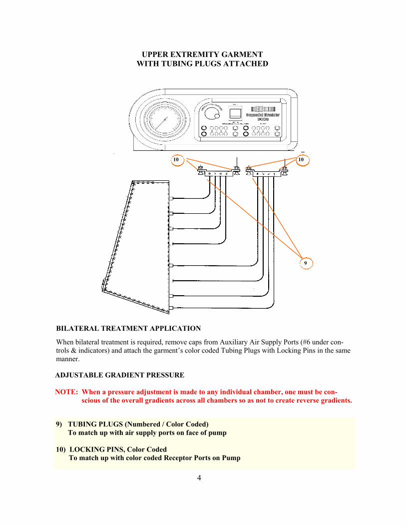
UPPER EXTREMITY GARMENT
WITH TUBING PLUGS ATTACHED
8
7 9
10 10
BILATERAL TREATMENT APPLICATION
When bilateral treatment is required, remove caps from Auxiliary Air Supply Ports (#6 under con-
trols & indicators) and attach the garment’s color coded Tubing Plugs with Locking Pins in the same
manner.
ADJUSTABLE GRADIENT PRESSURE
NOTE: When a pressure adjustment is made to any individual chamber, one must be con-
scious of the overall gradients across all chambers so as not to create reverse gradients.
9) TUBING PLUGS (Numbered / Color Coded)
To match up with air supply ports on face of pump
10) LOCKING PINS, Color Coded
To match up with color coded Receptor Ports on Pump
4
ELECTRICAL SPECIFICATIONS
The Model # 3008, Sequential Circulator’s electrical pump and components are
“double insulated” and thus do not require a “protective ground.” As a result, the
Model #3008 is equipped with an 18 gauge, 2-wire, 10 ft. power cord, secured through
the pump casing with a Heyco strain relief bushing.
Affixed to the rear exterior of the pump is a 3”x 3” Foil Label containing the
“Electrical Specifications” printed in contrasting black type. These specifications are
printed in both English and French and contain the following:
ELECTRICAL RATING: 120 VAC, 60Hz, 0.5 A
CARACTERISTIQUES ELECTRIQUES: 120 V c.a., 60 Hz, 0, 5 A
When servicing, use only identical replacement parts. Do not
remove cover. Refer to qualified service personnel.
Lors des reparations, utilisez, exclusivement des pieces de re
change identiques. No retirez pas le couvercle. Consultez un tech
niciaen qualifie.
WARNING: REPLACE FUSE WHERE MARKED
ADVERTISSEMENT: REMETTRE LE FUSIILE A L’ENDROIT INDIQUE
Fuse rated 3 Amps Time Delay, 250 VAC
Fusible de 3 A a retardemente, 250 V c.a.
Continuous Operation with Intermittent Loading
TYPE B—APPLIED PART CLASS II
Pie’ce Applique’e—Type B CLASSE II
ETL 9801681 CONFORMS TO
CONFROM A
CE UL Std 60601-1
Authorized service personnel, in addition to possessing proper tools and testing
equipment have access to electrical schematics, calibration criteria and an inventory
of identical replacement parts.
5
CLASSIFICATION
1. Class of protection against electrical shock..
CLASS II EQUIPMENT
2. The degree of protection against electric shock..
APPLIED PART—TYPE B
3. Mode..
CONTINUOUS OPERATION WITH INTERMITTENT LOADING
4. According degree of protection against ingress of water..
IPXO
FUSE REPLACEMENT
Occasionally power surges, etc. or normal age can result in a blown outer safety fuse lo-
cated in the rear of pump, adjacent to the power cord.
The safety fuse may be replaced by the user or caregiver, provided it is replaced with an
identical type (Buss MDL3 250V).
Prior to removal of fuse, disconnect power cord from socket. While pushing inward on
fuse cap, turn counter clockwise to release cap and remove fuse. After placing new fuse in
cap slot, push cap and fuse inward and turn clockwise to lock in place.
NOTE: The outer safety fuse is the only item serviceable by someone other than a Bio
Compression Systems technician at the factory. Bio Compression Systems
technicians have been trained specifically for the manufacturing and repair
of all Bio Compression Systems products.
Note: Having no “electromagnetic” or “radio frequency” signal sensitive type components,
this device neither generates, nor is it affected by any of this type of interference.
Further, its accuracy remains consistent in the presence of such devices emitting
this type of interference.
PUMP ENCLOSURE
The pump enclosure is constructed of “Cycolac” which is a trademark of
General Electric.
UL FLAME RATING: Under file #E47016, the UL Test method of UL 94, @ 23°C,
resulted in a Flammability Rating of (2.3 VO)
6
UNPACKING EQUIPMENT
SEQUENTIAL CIRCULATOR
By laying carton on its side, slide pump out with protective foam end caps still attached. Af-
ter removing pump from carton, foam end caps may be detached by gently pulling off each
side.
NOTE: Be sure to SAVE carton and end caps for future transporting or shipping. When
transporting, the carton is equipped with “fold-up” handles for easy carrying.
SLEEVE/GARMENT
Remove sleeve from package and unroll both tubing sections which are permanently attached
to garment with tubing plugs attached to the end of each tubing section.
OPERATING INSTRUCTIONS
Having familiarized yourself with the controls and features of this equipment, you are now
ready to begin your treatment according to your physician’s prescribed course of therapy.
1. Make sure that your circulator is plugged into a safe, properly secured, 110 V, AC outlet.
2. Place unit on a sturdy table or other type surface close to where you will be sitting. The
unit has non-slip-rubberized feet on the bottom, however placing paper or other items un-
derneath may defeat that purpose, causing unit to slide off of surface.
The Model SC-3008 operates at a faster inflation cycle per chamber which allows less time for
setting or adjusting the pressure in chamber #1 (the only chamber in which the pressure
should be set). Once the pressure has been set, the pump automatically adjusts for slightly
lower pressures in each chamber as it sequentially inflates each chamber in a distal to proxi-
mal direction. In preparation to adjust or set the pressure, to maximize available time, you
should first loosen the inner locking knob so that the pressure adjustment knob can immedi-
ately be adjusted without resistance. Observing the gauge needle will enable you to set the
desired pressure (turning the knob clockwise to raise the pressure and counter clockwise to
lower it.
NOTE: Remember, the pressure adjustment must be made before the pump cycles to cham-
ber #2. Should this occur, the pump must be re-set to inflation of chamber #1.
NOTE: Should it be necessary to re-set the pump to chamber #1 due to inadequate time to
complete the pressure adjustment, refer to “Internal One Hour Treatment Timer” in
paragraph #2 regarding early termination of treatment time.
7
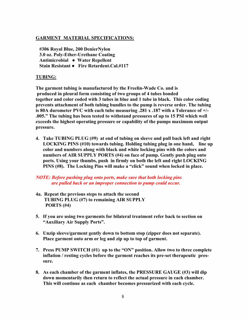
GARMENT MATERIAL SPECIFICATIONS:
#306 Royal Blue, 200 DenierNylon
3.0 oz. Poly-Ether-Urethane Coating
Antimicrobial ● Water Repellent
Stain Resistant ● Fire Retardent.Cal.#117
TUBING:
The garment tubing is manufactured by the Freelin-Wade Co. and is
produced in pleural form consisting of two groups of 4 tubes bonded
together and color coded with 3 tubes in blue and 1 tube in black. This color coding
prevents attachment of both tubing bundles to the pump is reverse order. The tubing
is 80A durometer PVC with each tube measuring .281 x .187 with a Tolerance of +/-
.005.” The tubing has been tested to withstand pressures of up to 15 PSI which well
exceeds the highest operating pressure or capability of the pumps maximum output
pressure.
4. Take TUBING PLUG (#9) at end of tubing on sleeve and pull back left and right
LOCKING PINS (#10) towards tubing. Holding tubing plug in one hand, line up
color and numbers along with black and white locking pins with the colors and
numbers of AIR SUPPLY PORTS (#4) on face of pump. Gently push plug onto
ports. Using your thumbs, push in firmly on both the left and right LOCKING
PINS (#8). The Locking Pins will make a “click” sound when locked in place.
NOTE: Before pushing plug onto ports, make sure that both locking pins
are pulled back or an improper connection to pump could occur.
4a. Repeat the previous steps to attach the second
TUBING PLUG (#7) to remaining AIR SUPPLY
PORTS (#4)
5. If you are using two garments for bilateral treatment refer back to section on
“Auxiliary Air Supply Ports”.
6. Unzip sleeve/garment gently down to bottom stop (zipper does not separate).
Place garment onto arm or leg and zip up to top of garment.
7. Press PUMP SWITCH (#1) up to the “ON” position. Allow two to three complete
inflation / resting cycles before the garment reaches its pre-set therapeutic pres-
sure.
8. As each chamber of the garment inflates, the PRESSURE GAUGE (#3) will dip
down momentarily then return to reflect the actual pressure in each chamber.
This will continue as each chamber becomes pressurized with each cycle.
8
END OF TREATMENT
1. Pull the left and right LOCKING PINS (#10) on both TUBING PLUGS (#9) out-
ward away from pump.
2. Grasp four tubes in hand just above TUBING PLUG (#9) and pull each plug in-
dividually outward away from pump to remove.
3. First gently bend your arm or leg (depending where garment is located) to re-
lease some air from chambers.
4. Continue to assist in the evacuation of air from garment, working from top to
bottom.
5. Once the garment feels loose enough, you can unzip the garment all the way to
bottom and remove.
NOTE: Repeat above steps if bilateral garments are used!
ADJUSTING GRADIENT PRESSURES
1. Model # SC-3008 Sequential Circulators provide total Calibrated Gradient
Pressure.
2. All gradients have been carefully calibrated at the factory resulting in the high-
est pressure in chambers #1 & #2 graduated down to the lowest in chambers #7
& #8.
3. The main PRESSURE ADJUSTMENT KNOB (#2) sets the pressure for sections
#1 & #2 of the sleeve. As it is adjusted, it will also raise or lower in proportion,
the remaining sections.
4. In the unlikely event you would wish to change the gradient settings calibrated
at the factory, it is possible to do so by using the “over-ride” adjustments (#8)
on the underside of the pump. (See “Overriding Pre-set Gradient Pressures”
next page)
5. We described earlier how the Pressure Gauge responds to filling pressures with
a brief “dip” before raising back up to the actual pressure
OVERRIDING PRE-SET GRADIENT PRESSURES
1. A small screw driver is the only tool needed to adjust the gradient pressures.
2. If you turn the pump on its side, you will notice underneath, three screw ports
labeled #3&4, #5&6 and #7&8, each having a directional arrow indicating the
way in which the pressure is increased.
9

3. It only takes a very small turn of the screw to adjust as you are adjusting
(mmHg) as reflected on the gauge.
4. With the pump on its side and while running, observe the gauge needle to set the
desired pressure.
10
WARRANTY INFORMATION
You can feel confident that your product is backed by the best warranty in the indus-
try covering any and all malfunctions (including parts and labor) resulting from com-
ponent and/or manufacturing defects.
Compression Pump = 3 years from date of purchase / invoice
Sleeves/Garments = 1 year from date of purchase/invoice
NOTES:_____________________________________________
Serial Number:_______________________________________
Date Purchased:______________________________________
Local Representative/Dealer:___________________________
Phone Number:______________________________________
REPAIR SERVICE
1-800-888-0908
BIO COMPRESSION SYSTEMS, INC.
120 West Commercial Ave., Moonachie, NJ 07074
www.biocompression.com
11
CLEANING INSTRUCTIONS
Exterior Case Cleaning Instructions:
Clean the exterior case and tubing with a damp (not wet) cloth using a mild soap and water
solution once per month or as needed. Do not allow liquids to enter the equipment, an electri-
cal hazard may be presented. Always allow the unit to dry before re-using. Garment Cleaning/Disinfecting Instructions:
Disconnect garment from device.
Open garment to expose all sides either by separating Velcro type hook and loop or by un-
zipping (depending on type of garments)
Use either a large sink or plastic tub able to hold enough solution (depending on size and
quantity of garments) to completely submerge garment/s under water including tubing,
with the exception of connectors at end of tubing. Solution should consist of 1/3 cup of Tide
or equivalent detergent per 1 gallon of warm tap water.
NOTE: IT IS EXTREMELY IMPORTANT THAT CONNECTORS AT END OF TUB-
ING BE KEPT OUT OF WATER AT ALL TIMES TO AVOID WATER FROM ENTER-
ING INTERIOR PORTION OF GARMENT/S.
Garment/s should be soaked for 1/2 hour with mild agitation of garment every 5 to 10
minutes while keeping it below surface of water
NOTE: Occasionally, harder to remove soiling on surface of garment may require addi-
tional washing by hand with a clean towel while submerged.
NOTE: In all cases, avoid using any abrasive type materials such as scrubbing pads or
chemicals that might cause damage to the exterior surface of garment.
Thoroughly rinse garment with warm tap water.
Re-submerge garment in solution consisting of 1 cup of Clorox bleach per gallon of warm
tap water for 1/2 hour, again agitating garment every 5 to 10 minutes while keeping gar-
ment/s below surface (with exception of tubing connector/s).
Rinse garment/s thoroughly and allow to air dry.
DO NOT place garment in washing machine or submerge in water unprotected from water
entering interior portion of garment where ultimate damage to pump can occur.
DO NOT use the tubing or valves as “handles” for carrying, hanging or storing garment/s.
In cases when it is necessary for a garment to be returned to the factory for repair or evalu-
ation, it is essential that garment/s are thoroughly cleaned and disinfected before returning.
12

OTHER BIO COMPRESSION SYSTEMS’ PRODUCTS
ALSO AVAILABLE:
SEQUENTIAL CIRCULATOR MODEL 2004
SEQUENTIAL CIRCULATOR MODEL 2004-FC (FAST
CYCLE)
SEQUENTIAL CIRCULATOR MODEL 3004
SEQUENTIAL CIRCULATOR MODEL 3004-FC (FAST
CYCLE)
SEQUENTIAL CIRCULATOR MODEL 2008
(EIGHT CHAMBER QUICK CYCLE)
THE BIOCRYO SYSTEM
MULTI-FLO DVT PROPHYLASIX SYSTEM
BIOARTERIAL PLUS
(ARTERIAL BLOOD FLOW ENHANCEMENT SYSTEM)
COMPRESSION THERAPY GARMENTS
INCLUDING OUR
CUSTOM GARMENTS
with the fastest turn around in the industry!
13

BIO COMPRESSION SYSTEMS
120 West Commercial Avenue
Moonachie, New Jersey 07074
Phone: 800-888-0908 Fax: 201-939-4503
Web site: www.biocompression.com
E-mail: [email protected]
Manual –3008 - Issue 12-10-99 Rev. 08-28-12-G