Embed Size (px)
Citation preview
N A T I O N A L A E R O N A U T I C S
Sequential Machines Paul1 and Unger Technique
M. M. Ebersole P. E. Lecoq
N O L O G Y
N A T I O N A L A E R O N A U T I C S A N D S P A C E A D M I N I S T R A T I O N
Technical Report No. 32-997
A Computer Program for Simplifying Incompletely Specified
Sequential Machines Using the Paul1 and Unger Technique
M. M. Ebersole
P. E. Lecoq
Approved by:
&V. Morris, Manager Guidance and Control Analysis and Integration Section
J E T P R O P U L S I O N L A B O R A T O R Y C A L I F O R N I A I N S T I T U T E O F TECHNOLOGY
PASADENA. C A L I F O R N I A
November 15, 1968

Copyright 0 1968 Jet Propulsion Laboratory
California Institute of Technology
Prepared Under Contract No. NAS 7-1 00 National Aeronautics & Space Administration
JPL TECHNICAL REPORT NO . 32-997
CONTENTS
1 . Introduction . . . . . . . . . . . . . . . . . . . . . 1
II . Sequential Machine Design Example: Shift Register Stage . . . . . . . . . . . . . . . . . . 1 A . Generation of Primitive Flow Table . . . . . . . . . . . . 1 B . Reduction of Number of Primitive Flow Table Rows 2 . . . . . . C . Shift Register Mechanization . . . . . . . . . . . . . . 2
111 . Determination of Compatible Pairs . . . . . . . . . . . . 3 A . Paull and Unger Process . . . . . . . . . . . . . . . . 3 B . Computer Mechanization . . . . . . . . . . . . . . . . 4
IV . Determination of Maximal Compatibles . . . . . . . . . . 6 A . Paull and Unger Process . . . . . . . . . . . . . . . . 6 B . Computer Mechanization . . . . . . . . . . . . . . . . 6
V Check for Closure: Paull and Unger Process 10 A . Definition . . . . . . . . . . . . . . . . . . . . . 10 B . Closure Procedure: Attempt 1 . . . . . . . . . . . . . . 10 C . Closure Procedure: Attempt 2 . . . . . . . . . . . . . . 10 D . Computer Mechanization . . . . . . . . . . . . . . . . 11
Appendix A . Operating Procedure . : . . . . . . . . . . . 14
Appendix B . Program Flow Diagrams . . . . . . . . . . . . 20
Appendix C . Program listing . . . . . . . . . . . . . . . . 37
References . . . . . . . . . . . . . . . . . . . . . . . 50
. . . . . . . . . .
1 . Primitive flow. shift register stage . . . . . . . . . . . . . . 1 2 . Reduced-row flow table for shift register stage . . . . . . . . . . 2
3 . Code assignment (excitation matrix) . . . . . . . . . . . . . 3
4 . Input (INTAB) . . . . . . . . . . . . . . . . . . . . . 3
5 . Typical input . . . . . . . . . . . . . . . . . . . . . 3
6 . Implication . . . . . . . . . . . . . . . . . . . . . . 4 7 . Final implication . . . . . . . . . . . . . . . . . . . . 4 8 . ITTAB matrix . . . . . . . . . . . . . . . . . . . . . 4
9.LOOKUP . . . . . . . . . . . . . . . . . . . . . . . 5
JPL TECHNICAL REPORT NO . 32-997
TABLES (Cont’d)
10.lNDEX . . . . . . . . . . . . . . . . . . . . . . . . 5
12 . Final implication . . . . . . . . . . . . . . . . . . . . 6
14 .Input . . . . . . . . . . . . . . . . . . . . . . . . 10
15 . Maximal compatibles . . . . . . . . . . . . . . . . . . 10
16.lnput . . . . . . . . . . . . . . . . . . . . . . . . 11
18 . Maximal compatible l is t . . . . . . . . . . . . . . . . . 11
20 . MACOMP after ADD. . . . . . . . . . . . . . . . . . . 12
21 . Maximal compatibles (MACOMPI in computer . . . . . . . . . 12
SELECT instructions . . . . . . . . . . . . . . . . . . . 12
23.lnput . . . . . . . . . . . . . . . . . . . . . . . . 12
24 . MACOMP . . . . . . . . . . . . . . . . . . . . . . 13
25 . Intersection of MACOMP and KTEMP . . . . . . . . . . . . . 13
26 . Entry in KEQUlV . . . . . . . . . . . . . . . . . . . . 13
A-1 . Typical sequential machine flow . . . . . . . . . . . . . .
A-3 . Instruction options . . . . . . . . . . . . . . . . . . . 16
1 1 . INDEX . . . . . . . . . . . . . . . . . . . . . . . . 5
13 . MACOMP (initial) . . . . . . . . . . . . . . . . . . . . 6
17 . Reduced machine table . . . . . . . . . . . . . . . . . . 11
19 . MACOMP after SELECT . . . . . . . . . . . . . . . . . . 11
22 . Resultant MACOMP after ADD. REPLACE. and
27 . Resulting reduced-row machine representation in KEQUIV . . . . . 13
14
. . . 16 A-2 . Input data for flow chart of Fig . A-1 (when using XEQSPAUI)
FIGURES
1 . Shift register stage . . . . . . . . . . . . 2 . NAND gate mechanization of shift register element
A.1 . Gross flow chart . . . . . . . . . . . . . A.2 . Typical problem printout . . . . . . . . . . A.3 . Typical problem typewriter input/output
8.1 . PAU1. Part 1
8.2 . PAU1, Part 2 . . . . . . . . . . . . . . 8.3 . PAU1. Part 3
B.4 . PA02 . Part 1 . . . . . . . . . . . . . .
. . . . . . . . . . . . . . . . . .
. . . . . . . . . . . . . .
. . . . . . . 1
. . . . . . . 3
. . . . . . . 15
. . . . . . . 17
. . . . . . . 17
. . . . . . . 21
. . . . . . . 22
. . . . . . . 23
. . . . . . . 24 B.5 . PAU2. Part 2 . . . . . . . . . . . . . . . . . . . . . 25
B.6 . PAU3. Part 1 . . . . . . . . . . . . . . . . . . . . . 25
JPL TECHNICAL REPORT NO . 32-997
FIGURES (Cont’d)
8.7 . PAU3.Part2 . . . . . . . . . . . . . . . . . . . . . 26
B.8 . PAU3. Part 3 . . . . . . . . . . . . . . . . . . . . . 27
8.9 . PAU3. Part 4 . . . . . . . . . . . . . . . . . . . . . 28
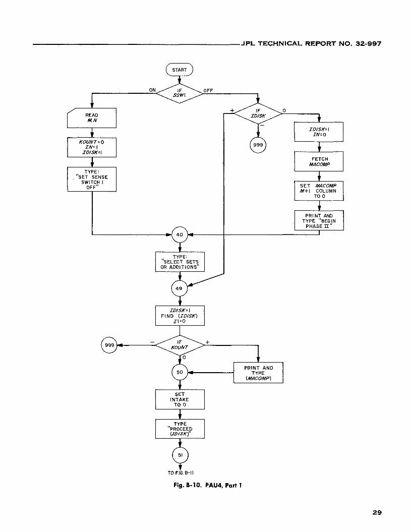
B.10 . PAU4. Part 1 . . . . . . . . . . . . . . . . . . . . . 29
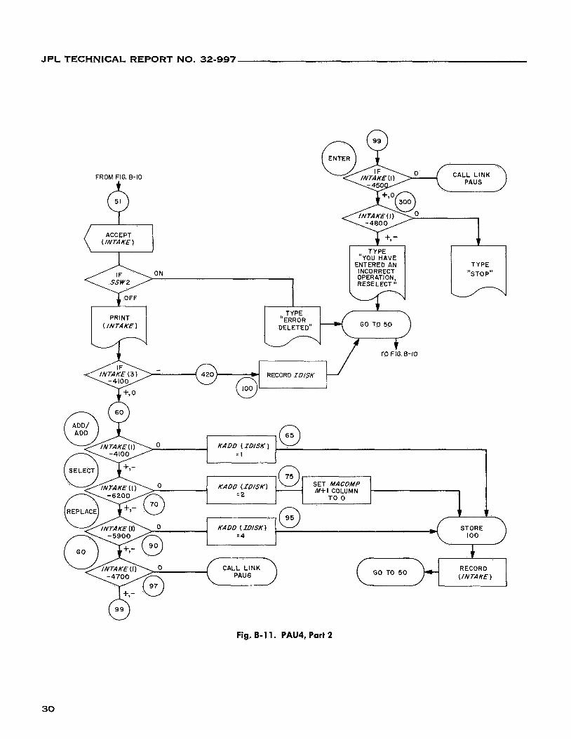
B.11 . PAU4. Part 2 . . . . . . . . . . . . . . . . . . . . . 30
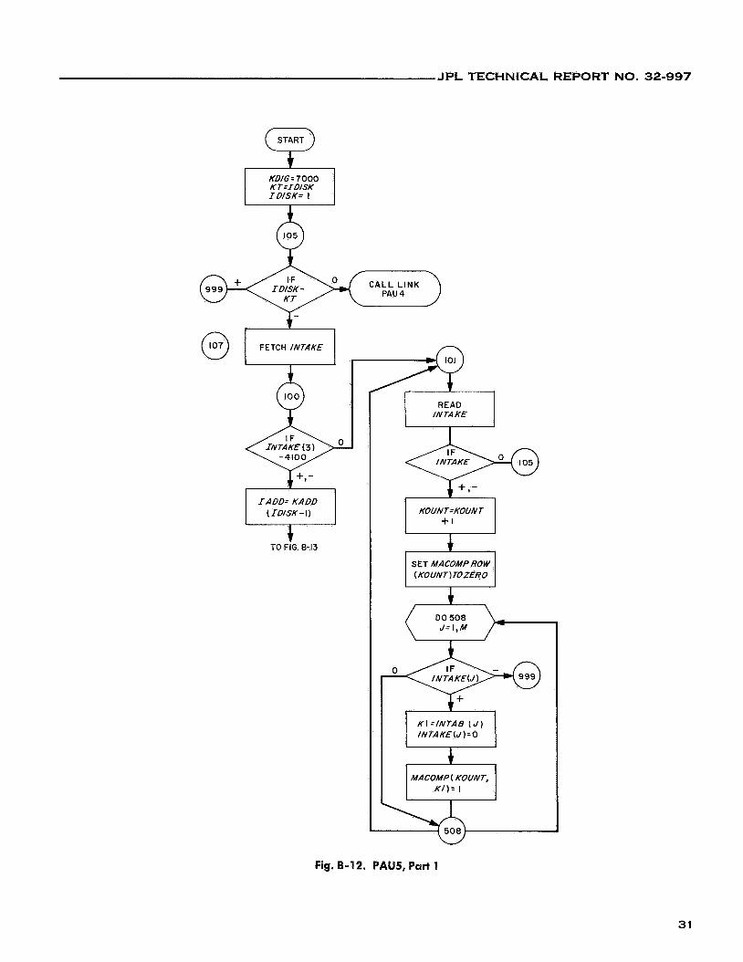
8.12 . PAUS. Part 1 . . . . . . . . . . . . . . . . . . . . . 31
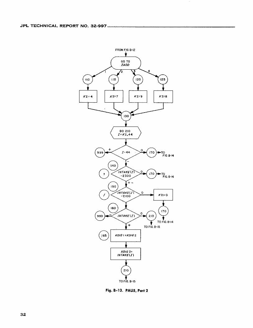
B.13 . PAUS. Part 2 . . . . . . . . . . . . . . . . . . . . . 32
B.14 . PAUJ. Part 3 . . . . . . . . . . . . . . . . . . . . . 33
8.15 . PAU5. Part 4 . . . . . . . . . . . . . . . . . . . . . 34
B.16 . PAU6. Part 1 . . . . . . . . . . . . . . . . . . . . . 34
8.17 . PAU6. Part 2 . . . . . . . . . . . . . . . . . . . . . 35
B.18 . PAU6. Part 3 . . . . . . . . . . . . . . . . . . . . . 36
V
JPL TECHNICAL REPORT NO. 32-997
ABSTRACT This report presents a description of a computer program mecha-
nized to perform the Paull and Unger process of simplifying incom- pletely specified sequential machines. An understanding of the process, as given in Ref. 3, is a prerequisite to the use of the techniques pre- sented in this report. This process has specific application in the design of asynchronous digital machines and was used in the design of opera- tional support equipment for the Mariner 1966 central computer and sequencer. A typical sequential machine design problem is presented to show where the Paull and Unger process has application. A descrip- tion of the Paull and Unger process together with a description of the computer algorithms used to develop the program mechanization are presented. Several examples are used to clarify the Paull and Unger process and the computer algorithms. Program flow diagrams, pro- gram listings, and a program user operating procedures are included as appendixes.
VI
JPL TECHNICAL REPORT NO. 32-997
1. INTRODUCTION
The example of the design of a shift register stage, using only NAND gates, will show how the Paull and Unger process, when applied to a sequential machine design problem, yields a simplified mechanization.
defined so that programming a digital computer to per- form the process was feasible. Those steps in the process that require trial and error decisions are left up to the program user, who may enter these decisions into the computer on line via the typewriter.
Hand computations of the Paull and Unger process are tedious, and often computational errors result. The ma- jority of the steps in the process are sufficiently well
Running several typical design problems on the com- puter has shown the merit of the computer program, both in design time savings and computational accuracy.
II. SEQUENTIAL MACHINE DESIGN
A. Generation of Primitive Flow Table
generation of a shift register stage (see Ref. 1). The following properties characterize the design and
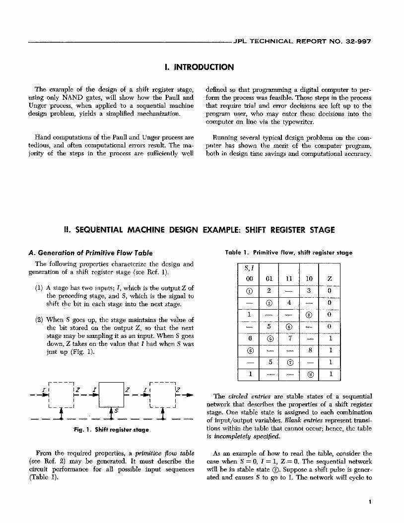
(1) A stage has two inputs; I, which is the output Z of the preceding stage, and S, which is the signal to shift the bit in each stage into the next stage.
(2) When S goes up, the stage maintains the value of the bit stored on the output Z, so that the' next stage may be sampling it as an input. When S goes down, Z takes on the value that I had when S was just up (Fig. 1).
Fig. 1. Shift register stage
From the required properties, a primitive flow table (see Ref. 2) may be generated. It must describe the circuit performance for all possible input sequences (Table 1).
EXAMPLE: SHIFT REGISTER STAGE
Table 1. Primitive flow, shift register stage
The circled entries are stable states of a sequential network that describes the properties of a shift register stage. One stable state is assigned to each combination of input/output variables. Blank entries represent transi- tions within the table that cannot occur; hence, the table is incompletely specified.
As an example of how to read the table, consider the case when S = 0, I = 1, Z = 0. The sequential network will be in stable state 0. Suppose a shift pulse is gener- ated and causes S to go to 1. The network will cycle to
1
JPL TECHNICAL REPORT NO. 32-997
the S = 1, Z = 1, Z = 0 entry in the same row, in this case an uncircled 4, which is an unstable state. The unstable entry is an indication of which stable state the network is next to assume for a particular input variable combi- nation; the network thus assumes stable state 0.
Suppose that the shift pulse S returns to 0, so that S = 0, Z = 1, Z = 0. The network cycles to the 010 entry, which is unstable 5. Then, as just described, the transfer is to stable state 0, and the corresponding output is a 1.
The preceding sequence adheres to the desired prop- erties of the shift register stage. All other input variable sequences will also exhibit the desired shift register properties.
0. Reduction of Number of Primitive Flow Table RQWS If it is possible to reduce the number of rows in the
primitive flow table, ultimately the complexity of the net- work having the properties of a shift register stage will be reduced.
Basically, row reduction is accomplished by merging rows of the primitive flow table so that the desired se- quential network properties are preserved.
One method for row reduction (state reduction) has been suggested by M. C. Paull and S. H. Unger (see Ref. 3). The Paull and Unger method consists of the fol- lowing three steps:
(1) Determination of compatible row pairs
(2) Determination of larger row combinations, called maximal compatibles
(3) Selection of either maximal compatibles or subsets of maximal compatibles, which become single states of a reduced row network ,
The three steps will be described in detail on pages 3 through 13. Let it suffice for now to say that the Paull and Unger method, when applied to the shift register problem, yields the reduced-row flow table (Table 2).
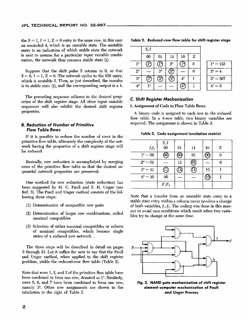
Note that rows 1,2, and 3 of the primitive flow table have been combined to form one row, denoted as 1%. Similarly, rows 5, 6, and 7 have been combined to form one row, namely 3*. Other row assignments are shown in the tabulation to the right of Table 2.
Table 2. Reduced-row flow table for shift register stage
I
C. Shift Register Mechanization
1. Assignment of Code to Flow Table Rows
A binary code is assigned to each row in the reduced flow table. In a 4-row table, two binary variables are required. The assignment is shown in Table 3.
Table 3. Code assignment (excitation matrix)
Note that a transfer from an unstable state entry to a stable state entry within a column never involves a change of both variables, fl, f 2 . The coding was done in this man- ner to avoid race conditions which result when two varia- bles try to change at the same time.
Fig. 2. NAND gate mechanization of shift register element computer mechanization of Paul1
and Unger Process
2
JPL TECHNICAL REPORT NO. 32-997
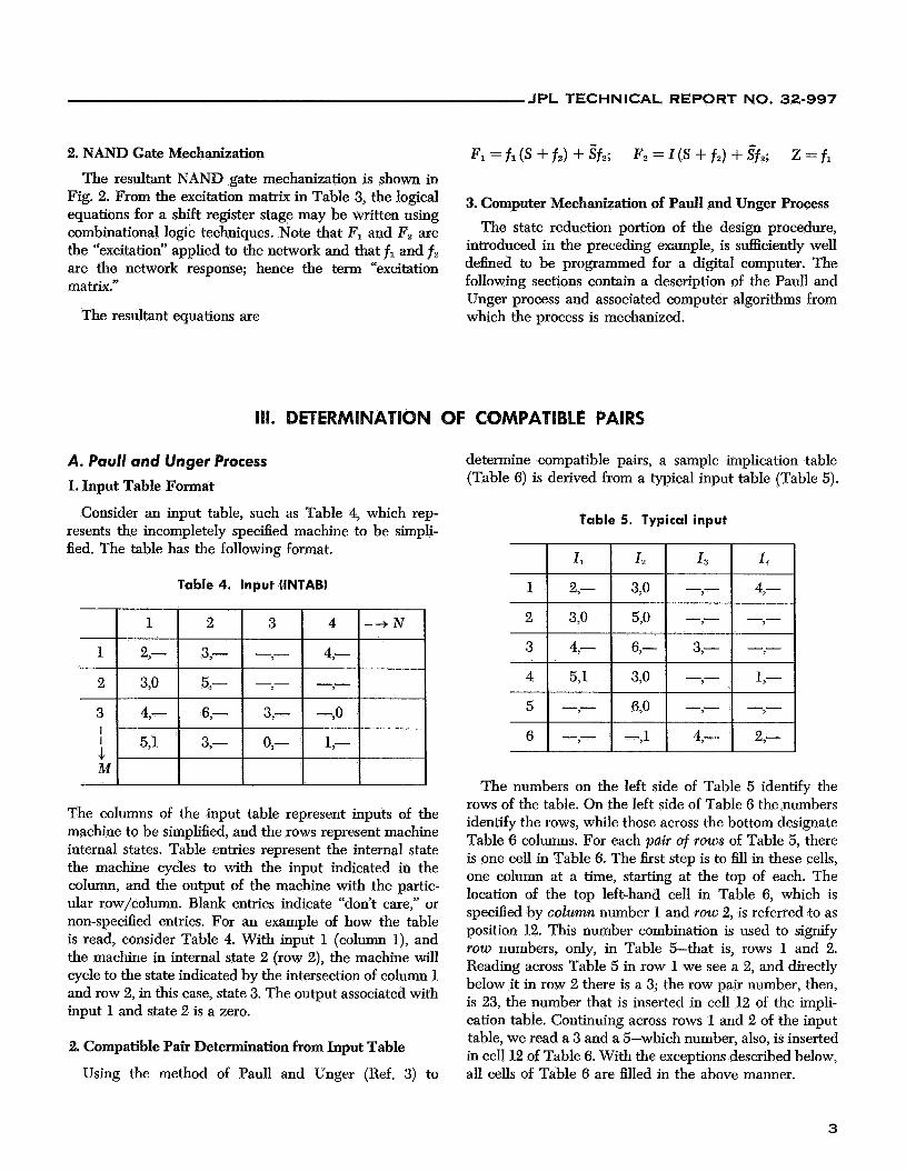
2. NAND Gate Mechanization
The resultant NAND gate mechanization is shown in Fig. 2. From the excitation matrix in Table 3, the logical equations for a shift register stage may be written using combinational logic techniques. Note that F, and F, are the “excitation” applied to the network and that fi and f i are the network response; hence the term “excitation matrix.”
The resultant equations are
3. Computer Mechanization of Paull and Unger Process The state reduction portion of the design procedure,
introduced in the preceding example, is sufficiently well defined to be programmed for a digital computer. The following sections contain a description of the Paull and Unger process and associated computer algorithms from which the process is mechanized.
111. DETERMINATION OF COMPATIBLE PAIRS
A. Paull and Unger Process
1. Input Table Format
Consider an input table, such as Table 4, which rep- resents the incompletely specified machine to be simpli- fied. The table has the following format.
Table 4. Input (INTAB)
1 2,- 3,- -,- 4,-
2 3,O 5,- -,- -e
The columns of the input table represent inputs of the machine to be simplified, and the rows represent machine internal states. Table entries represent the internal state the machine cycles to with the input indicated in the column, and the output of the machine with the partic- ular row/column. Blank entries indicate “don’t care,” or non-specified entries. For an example of how the table is read, consider Table 4. With input 1 (column I), and the machine in internal state 2 (row 2), the machine will cycle to the state indicated by the intersection of column 1 and row 2, in this case, state 3. The output associated with input 1 and state 2 is a zero.
2. Compatible Pair Determination from Input Table
Using the method of Paull and Unger (Ref. 3) to
determine compatible pairs, a sample implication table (Table 6) is derived from a typical input table (Table 5).
Table 5. Typical input
The numbers on the left side of Table 5 identify the rows of the table. On the left side of Table 6 the numbers identify the rows, while those across the bottom designate Table 6 columns. For each pair of rows of Table 5, there is one cell in Table 6. The first step is to fill in these cells, one column at a time, starting at the top of each. The location of the top left-hand cell in Table 6, which is specified by column number 1 and row 2, is referred to as position 12. This number combination is used to signify TOW numbers, only, in Table 5-that is, rows 1 and 2. Reading across Table 5 in row 1 we see a 2, and directly below it in row 2 there is a 3; the row pair number, then, is 23, the number that is inserted in cell 12 of the impli- cation table. Continuing across rows 1 and 2 of the input table, we read a 3 and a 5-which number, also, is inserted in cell 12 of Table 6. With the exceptions described below, all cells of Table 6 are filled in the above manner.
3
JPL TECHNICAL REPORT NO. 32-997
Table 6. Implication
3 l~ 4
5
6
I 36 I 56 I
~~ * , 34
1 2 3 4 5
Table 7. Final implication
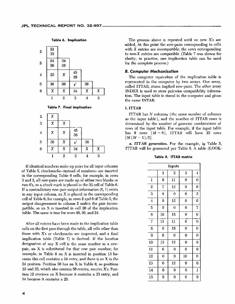
The process above is repeated until no new X’s are added, At this point the row-pairs corresponding to cells with X entries are incompatible; the rows corresponding to non-X entries are compatible. (Table 7 was shown for clarity; in practice, one implication table can be used for the complete process.)
6. Computer Mechanization The computer equivalent of the implication table is
represented in the computer by two arrays. One array, called ITTAB, stores implied row-pairs. The other array INDEX is used to store pairwise compatibility informa- tion. The input table is stored in the computer and given the name INTAB.
1. ITTAB ITTAB has N columns (the same number of columns
as the input table), and the number of ITTAB rows is determined by the number of pairwise combinations of rows of the input table. For example, if the input table has 6 rows ( M = 6 ) , ITTAB will have 15 rows
a. ITTAB generation. For the example, in Table 5, ITTAB will be generated per Table 8. A table (LOOK-
[ M ( M - 1)/21.
1 2 3 4 5 Table 8. ITTAB matrix
If identical numbers make up pairs for all input columns of Table 5, checkmarks-instead of numbers-are inserted in the corresponding Table 6 cells; for example, in rows 3 and 5, all row-pairs are made up of either two blanks or two 6’s, so a check mark is placed in the 35 cell of Table 6. If a contradictory row-pair output information (0, 1) exists in any input column, an X is placed in the corresponding cell of Table 6; for example, in rows 2 apd 6 of Table 5, the output disagreement in column 2 makes the pair incom- patible, so an X is inserted in cell 26 of the implication table. The same is true for rows 46,56, and 24.
After all entries have been made in the implication table cells on the first pass through the table, all cells other than those with Xs or checkmarks are inspected, and a final implication table (Table 7) is derived. If the location designation of any X cell is the same number as a row- pair, an X is substituted for that row pair number; for example, in Table 6 an X is inserted in position 13 be- cause this cell contains a 24 entry, and there is an X in the 24 position. Position 56 has an X in Table 6, so positions 23 and 25, which also contain 56 entries, receive Xs. Posi- tion 12 receives an X because it contains a 23 entry, and 14 because it contains a 25.
4 0
Inputs I
~
12
~
0 0
I lo I 6 15 0 0
I I I I 8 I O 1 1 5 1 0 I O
4
JPL TECHNICAL REPORT NO. 32-997
1
2
3
4
5
6
7 8
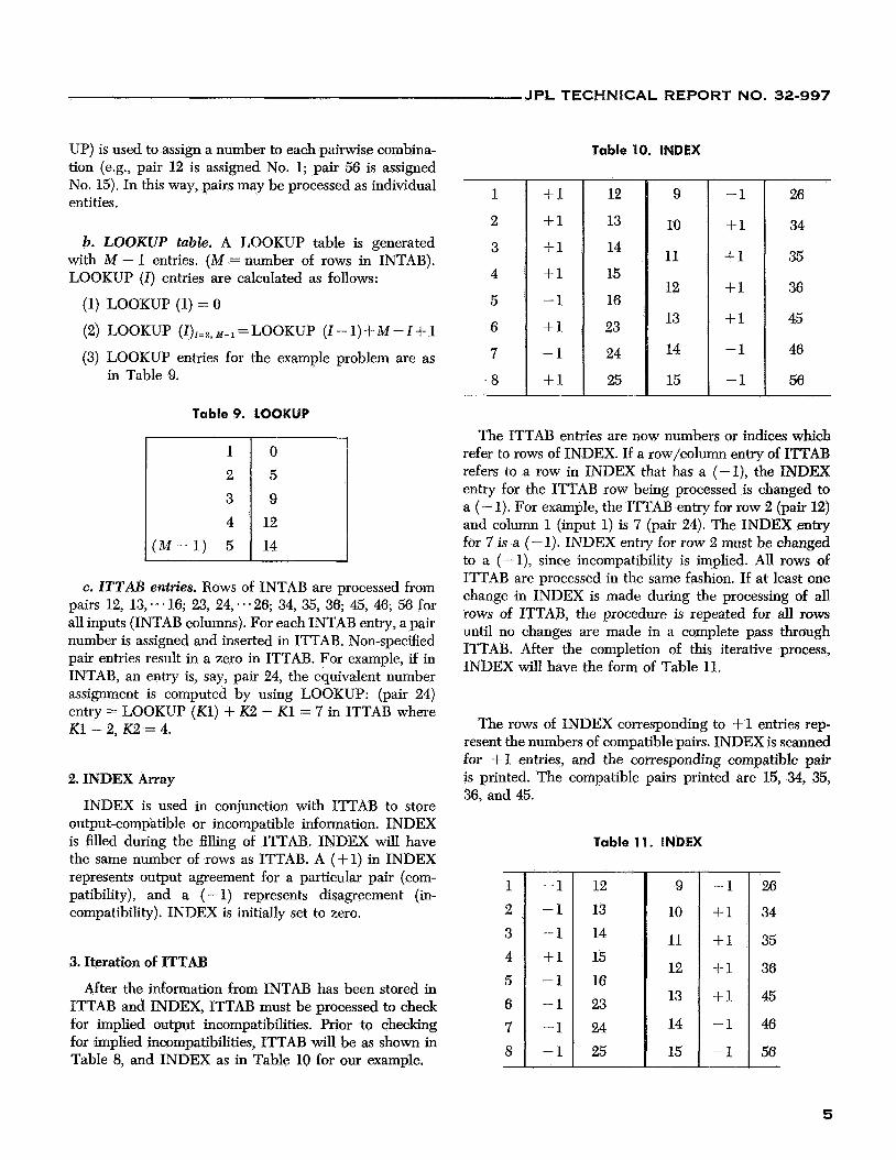
UP) is used to assign a number to each pairwise combina- tion (e.g., pair 12 is assigned No. 1; pair 56 is assigned No. 15). In this way, pairs may be processed as individual entities, +l 12
+1 13
+l 14
+1 15
-1 16
+l 23
-1 24
+1 25
b. LOOKUP table. A LOOKUP table is generated with M - 1 entries. (M = number of rows in INTAB). LOOKUP (I) entries are calculated as follows:
(1) LOOKUP (1) = 0
(2) LOOKUP (I),=,,,-,=LOOKUP (I-l)+M-I+l (3) LOOKUP entries for the example problem are as
in Table 9.
9
10
11
12
13
14
15
Table 9. LOOKUP
-1
+1
+1
$1
+1
-1
-1
c. ZTTAB entries. Rows of INTAB are processed from pairs 12, 13,e.e 16; 23, 24, .*-26; 34, 35, 36; 45, 46; 56 for all inputs (INTAB columns). For each INTAB entry, a pair number is assigned and inserted in ITTAB. Non-specified pair entries result in a zero in ITTAB. For example, if in INTAB, an entry is, say, pair 24, the equivalent number assignment is computed by using LOOKUP: (pair 24) entry = LOOKUP (Kl) + K2 - K1= 7 in ITTAB where K1= 2, K2 = 4.
2. INDEX Array
INDEX is used in conjunction with ITTAB to store output-compatible or incompatible information. INDEX is filled during the filling of ITTAB. INDEX will have the same number of rows as ITTAB. A ( + 1) in INDEX represents output agreement for a particular pair (com- patibility), and a (- 1) represents disagreement (in- compatibility). INDEX is initially set to zero.
3. Iteration of ITTAB
After the information from INTAB has been stored in ITTAB and INDEX, ITTAB must be processed to check for implied output incompatibilities. Prior to checking for implied incompatibilities, ITTAB will be as shown in Table 8, and INDEX as in Table 10 for our example.
Table 10. INDEX
26
34
35
36
45
46
56
The ITTAB entries are now numbers or indices which refer to rows of INDEX. If a row/column entry of ITTAB refers to a row in INDEX that has a (-l), the INDEX entry for the ITTAB row being processed is changed to a (- 1). For example, the ITTAB entry for row 2 (pair 12) and column 1 (input 1) is 7 (pair 24). The INDEX entry for 7 is a (- 1). INDEX entry for row 2 must be changed to a (-1), since incompatibility is implied. All rows of ITTAB are processed in the same fashion. If at least one change in INDEX is made during the processing of all rows of ITTAB, the procedure is repeated for all rows until no changes are made in a complete pass through ITTAB. After the completion of this iterative process, INDEX will have the form of Table 11.
The rows of INDEX corresponding to +l entries rep- resent the numbers of compatible pairs. INDEX is scanned for +l entries, and the corresponding compatible pair is printed. The compatible pairs printed are 15, 34, 35, 36, and 45.
Table 11. INDEX
+l
- 26
34
35
36
45
46
56
5
JPL TECHNICAL REPORT NO. 32-997
IV. DETERMINATION OF MAXIMAL COMPATIBLES
A. Paull and Unger Process
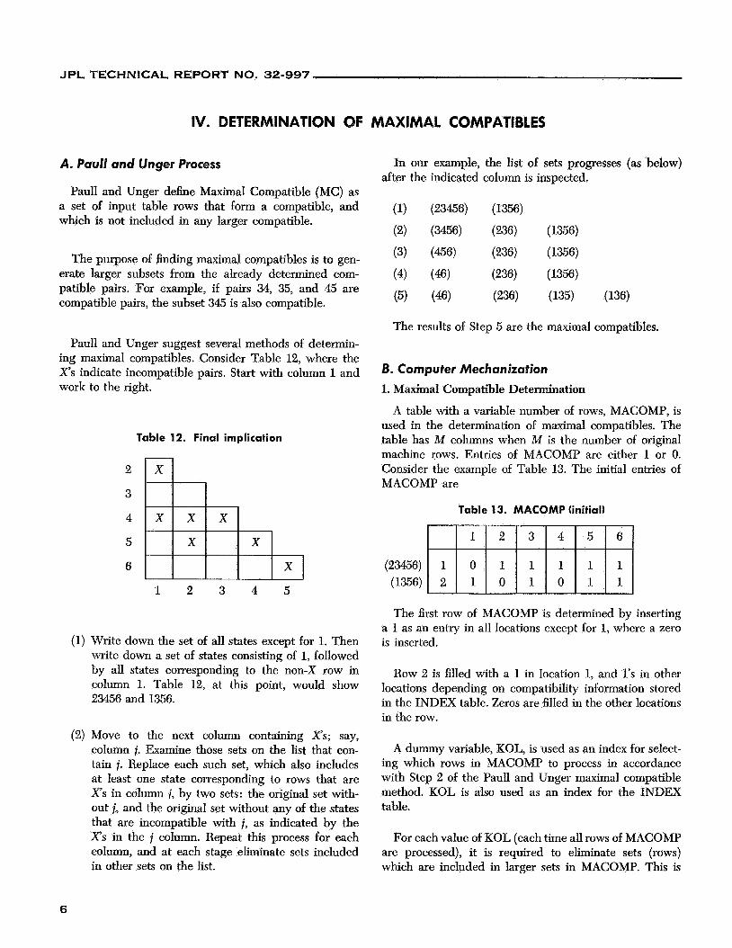
Paull and Unger define Maximal Compatible (MC) as a set of input table rows that form a compatible, and which is not included in any larger compatible.
The purpose of finding maximal compatibles is to gen- erate larger subsets from the already determined com- patible pairs. For example, if pairs 34, 35, and 45 are compatible pairs, the subset 345 is also compatible.
Paull and Unger suggest several methods of determin- ing maximal compatibles. Consider Table 12, where the X s indicate incompatible pairs. Start with column 1 and work to the right.
Table 12. Final implication
1 2 3 4 5
(1) Write down the set of all states except for 1. Then write down a set of states consisting of 1, followed by all states corresponding to the non-X row in column 1. Table 12, at this point, would show 23456 and 1356.
(2) Move to the next column containing X s ; say, column i. Examine those sets on the list that con- tain i. Replace each such set, which also includes at least one state corresponding to rows that are X’s in column i, by two sets: the original set with- out i, and the original set without any of the states that are incompatible with i, as indicated by the X’s in the i column. Repeat this process for each column, and at each stage eliminate sets included in other sets on the list.
In our example, the list of sets progresses (as below) after the indicated column is inspected.
(1) (23456) (1356)
(2) (3456) (236) (1356)
(3) (456) (236) (1356)
(4) (46) (236) (1356)
(5) (46) (236) (135) (136)
The results of Step 5 are the maximal compatibles.
B. Computer Mechanization 1. Maximal Compatible Determination
A table with a variable number of rows, MACOMP, is used in the determination of maximal compatibles. The table has A4 columns when M is the number of original machine rows. Entries of MACOMP are either 1 or 0. Consider the example of Table 13. The initial entries of MACOMP are
Table 13. MACOMP (initial)
(23456) (1356)
~ 2 0 0
The first row of MACOMP is determined by inserting a 1 as an entry in all locations except for 1, where a zero is inserted.
Row 2 is filled with a 1 in location 1, and 1’s in other locations depending on compatibility information stored in the INDEX table. Zeros are filled in the other locations in the row.
A dummy variable, KOL, is used as an index for select- ing which rows in MACOMP to process in accordance with Step 2 of the Paull and Unger maximal compatible method. KOL is also used as an index for the INDEX table.
For each value of KOL (each time all rows of MACOMP are processed), it is required to eliminate sets (rows) which are included in larger sets in MACOMP. This is
6
JPL TECHNICAL REPORT NO. 32-997
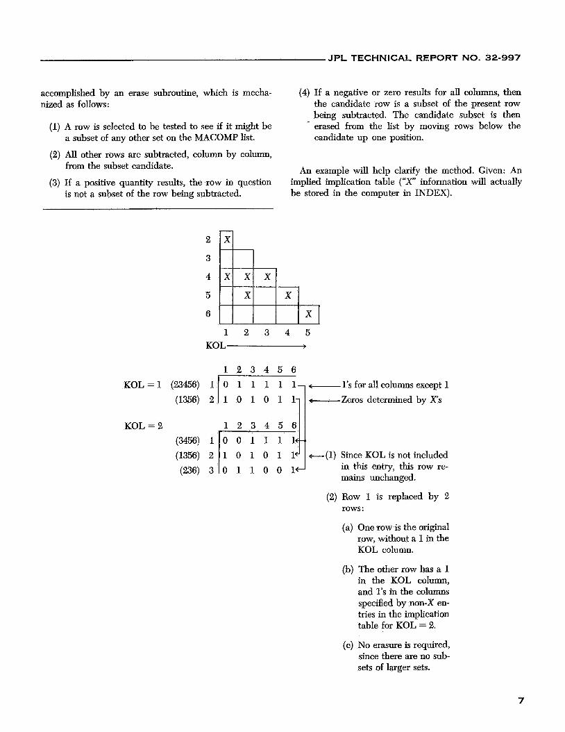
accomplished by an erase subroutine, which is mecha- nized as follows:
(1) A row is selected to be tested to see if it might be a subset of any other set on the MACOMP list.
(2) All other rows are subtracted, column by column, from the subset candidate.
(3) If a positive quantity results, the row in question is not a subset of the row being subtracted.
(4) If a negative or zero results for all columns, then the candidate row is a subset of the present row being subtracted. The candidate subset is then erased from the list by moving rows below the candidate up one position.
An example will help clarify the method. Given: An implied implication table (“X” information will actually be stored in the computer in INDEX).
1 2 3 4 5 KOL >
1 2 3 4 5 6
-1’s for allcolumns except 1 -Zeros determined by X’s
1 2 3 4 5 6
+(1) Since KOL is not included in this entry, this row re- mains unchanged.
(2) Row 1 is replaced by 2 rows :
KOL = 2
(a) One row is the original row, without a 1 in the KOL column.
(b) The other row has a 1 in the KOL column, and 1’s in the columns specified by non-X en- tries in the implication table for KOL = 2.
(c) No erasure is required, since there are no sub- sets of larger sets.
7
JPL TECHNICAL REPORT NO. 32-997
1 0 0 0 1 16- 0 1 0 0 0 IC-.
KOL = 3 1 2 3 4 5 6
0 0 1 0 1 le
(before ERASE) (456) 1 (156) 2
(26) 3 (356) 4
(1356) 5 (236) 6
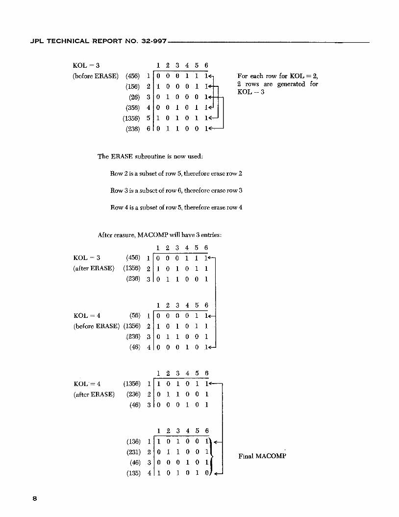
The ERASE subroutine is now used:
Row 2 is a subset of row 5, therefore erase row 2
Row 3 is a subset of row 6, therefore erase row 3
Row 4 is a subset of row 5, therefore erase row 4
After erasure, MACOMP u7ill have 3 entries:
1 2 3 4 5 6
(after ERASE) KOL = 3
1 2 3 4 5 6
For each row for KOL = 2, 2 rows are generated for KOL = 3
KOL = 4 (56) 1 (before ERASE) (1356) 2
(236) 3
(46) 4
KOL = 4 (1356) 1 (after ERASE) (236) 2
(46) 3
(136) 1 (231) 2
(46) 3 (135) 4
0 0 0 0 1 1 c 1 0 1 0 1 1 0 1 1 0 0 1 O O O l O l t
1 2 3 4 5 6 1 0 1 0 1 l c - 0 1 1 0 0 1 0 0 0 1 0 1
1 2 3 4 5 6 l O l O O l t 0 1 1 0 0 1 0 0 0 1 0 1 1 0 1 0 1 0 4 + I Final MACOMP
8
JPL TECHNICAL REPORT NO. 32-997
The final MACOMP table is scanned for l’s, and the resultant maximal compatibles printed. In this case they are 136, 236,46, and 135.
2. Determination of Lower Bound on Number of States in the Minimized Table
The procedure for finding maximal compatibles can also be used to determine a lower bound of the number of states in a minimized table. All that need be done is to change the X’s with the non-X entries in the implication table (in the computer exchange (+l), and -1 in the INDEX table).
The rows of MACOMP are now referred to as muxima1 incompatibles. The number of elements in the largest maximal incompatible is a lower bound on the number of rows in the reduced table. (The maximum number of 1’s in any row of MACOMP will be the upper bound).
A dummy variable, INC, is used to indicate to the maxi- mal compatible program, whether the maximal compati- bles are to be determined, or the lower bound is to be determined. The program presently determines MC’s first (INC = -l), and the lower bound second (INC = + or 0).
9

JPL TECHNICAL REPORT NO. 32-997
V. CHECK FOR CLOSURE: PAUL1 AND UNGER PROCESS
The maximal compatibles, computed in Part I1 of the program, are candidates for internal states of a new machine with a reduced number of internal states. There remains to check selected candidates for closure.
A. Definition
necessarily disjoint) will be said to be closed if: A grouping of all rows of a flow table into C sets (not
(1) Every set implied by Ci is included in one of the C sets (where i = the number of the Cth set).
(2) The output 2 ( p , l k ) = 2 (t, l k ) , for all row pairs ( p , t ) in Ci for every lk and i .
Condition (2) is satisfied by the compatible pair and maxi- mal compatible portions of the program. A test to deter- mine whether condition (1) is satisfied is demonstrated in Part B of this section.
The mechanics of testing for closure may best be described by an example. Consider an input table and the maximal compatibles generated from input table information:
Table 14. Input
1, I , 1,
Table 15. Maximal compatibles
B. Closure Procedure: Attempt 7 Choose from the maximal compatible table entries whose union covers all of the internal states of the original machine. In our example, an obvious choice would be entries 1 and 3: 1234 U 56 = 123456.
Assign new numbers to the chosen entries so as to distinguish them from original input table entries:
The chosen sets must be checked vs the input table for all inputs for satisfaction of condition (1) in the definition of closure.
(a) 1" with input I , implies 56:
1:# (II) -+ 56,
since 56 = 2*, condition (1) of the closure defi- nition is met.
(b) 1$ with input I , implies 36:
1" (12) -+ 36,
since 36 is not included as one of the chosen sets, condition (1) of the closure definition is not satisfied. The chosen sets, therefore, do not satisfy the closure criteria and another selection must be made.
It should be noted that since 1:' and 2 form the only covering of the original machine states using two entries, at least three entries (rows of the reduced machine) are required.
C. Closure Procedure: Attempt 2
(1) Since states 1 and 4 of the original machine are members of only maximal compatible set 1, it is imperative that set 1, or subsets of set 1, be included in the group of chosen candidates for the reduced machine.
Suppose subsets 12 and 34 of 1234 are chosen. (Sub- sets of larger compatible sets are also compatibles.) Pair 56 is chosen so that the union of 12,34,56 forms a covering of input states of the original machine.
1 0
JPL TECHNICAL REPORT NO. 32-997
1 2 3 4
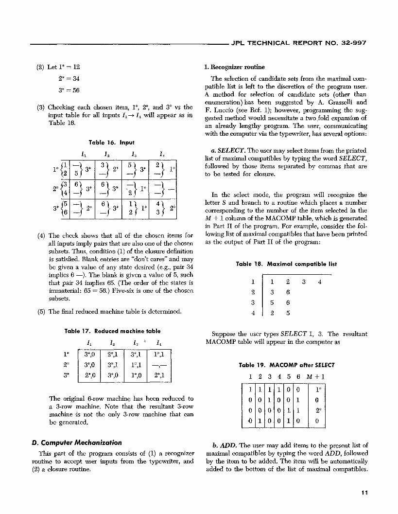
(2) Let 1* = 12 2* = 34
3* = 56
1 2 3 4 3 6 5 6 2 5
(3) Checking each chosen item, 1*, 2*, and 3* vs the input table for all inputs 11-+ I, will appear as in Table 16.
Table 16. Input
(4) The check shows that all of the chosen items for all inputs imply pairs that are also one of the chosen subsets. Thus, condition (1) of the closure definition is satisfied. Blank entries are “don’t cares” and may be given a value of any state desired (e.g., pair 34 implies 6 -). The blank is given a value of 5, such that pair 34 implies 65. (The order of the states is immaterial: 65 = 56.) Five-six is one of the chosen subsets.
(5) The final reduced machine table is determined.
Table 17. Reduced machine table
I1 I, I, a 1 4
l* 2k ~1 -- 3* 2*,0 2*,1
The original 6-row machine has been reduced to a $row machine. Note that the resultant &row machine is not the only h o w machine that can be generated.
D. Computer Mechanization This part of the program consists of (1) a recognizer
routine to accept user inputs from the typewriter, and (2) a closure routine.
1. Recognizer routine
The selection of candidate sets from the maximal com- patible list is left to the discretion of the program user. A method for selection of candidate sets (other than enumeration) has been suggested by A. Grasselli and F. Luccio (see Ref. 1); however, programming the sug- gested method would necessitate a two fold expansion of an already lengthy program. The user, communicating with the computer via the typewriter, has several options:
a. SELECT. The user may select items from the printed list of maximal compatibles by typing the word SELECT, followed by those items separated by commas that are to be tested for closure.
In the select mode, the program will recognize the letter S and branch to a routine which places a number corresponding to the number of the item selected in the M + 1 column of the MACOMP table, which is generated in Part I1 of the program. For example, consider the fol- lowing list of maximal compatibles that have been printed as the output of Part I1 of the program:
Table 18. Maximal compatible list
Suppose the user types SELECT1 1, 3. The resultant MACOMP table will appear in the computer as
Table 19. MACOMP after SELECT
1
~
2 3 4 5 6 M + 1
~~ 1 1
1 0
b. ADD. The user may add items to the present list of maximal compatibles by typing the word ADD, followed by the item to be added. The item will be automatically added to the bottom of the list of maximal compatibles.
11
JPL TECHNICAL REPORT NO. 32-997
-
5,O 6,O - -
3,O
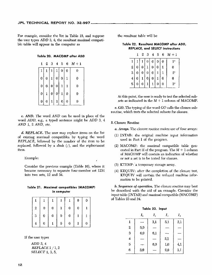
For example, consider the list in Table 18, and suppose the user types ADD 3, 4; the resultant maximal compati- ble table will appear in the computer as
391 -
6,l
670 -
-
Table 20. MACOMP after ADD
1
1
0
0
0
0
-
-
2
1
0
0
1
0
-
-
3 4
~
5 6 M S 1
~~ 1 0
0 0
c. AND. The word AND can be used in place of the word ADD, e.g., a typed sentence might be ADD 3, 4 AND 1, 2 AND, etc.
d. REPLACE. The user may replace items on the list of existing maximal compatibles by typing the word REPLACE, followed by the number of the item to be replaced, followed by a slash (/), and the replacement item.
Example:
Consider the previous example (Table 16), where it became necessary to separate four-member set 1234 into two sets, 12 and 34.
I
Table 21. Maximal compatibles (MACOMP) in computer
~
4 0
If the user types
ADD 3 , 4 REPLACE 1 / 1,2 SELECT 1, 3, 5,
~
0 0
the resultant table will be
Table 22. Resultant MACOMP after ADD, REPLACE, and SELECT instructions
- 1 2 3 4 5 -
1 2 3 4 5
1 1 0 0 0 0 0 1 0 0 0 0 0 0 1 0 1 0 0 1
~ 0 0 1 1 0
6
0 1 1 0 0
-
_.
M + l
At this point, the user is ready to test the selected sub- sets as indicated in the A4 + 1 column of MACOMP.
e. GO. The typing of the word GO calls the closure sub- routine, which tests the selected subsets for closure.
2. Closure Routine
a. Arrays. The closure routine makes use of four arrays:
(1) INTAB: the original machine input information used in Part I of the program.
(2) MACOMP: the maximal compatible table gen- erated in Part I1 of the program. The M + 1 column of MACOMP will contain an indication of whether or not a set is to be tested for closure.
(3) KTEMP: a temporary storage array.
(4) KEQUIV: after the completion of the closure test, KEQUIV will contain the reduced machine infor- mation to be printed.
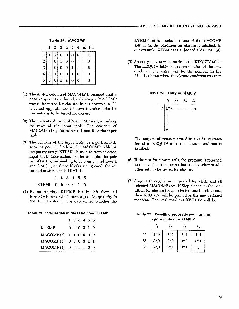
b. Sequence of operation. The closure routine may best be described with the aid of an example. Consider the input table (INTAB) and maximal compatible (MACOMP) of Tables 23 and 24.
Table 23. Input
11 I, I,
12
JPL TECHNICAL REPORT NO. 32-997
- 1 2 3 4 5 -
Table 24. MACOMP
1 2 - 1 0 0 0 0 -
3
0 1
0 0 1
-
-
4
0 0 0 0 1
-
-
5
0 0 1 1
0
-
__
6 M + l - 0 1
1
0 0 __
1” 0 2* 0 3*
(1) The M + 1 column of MACOMP is scanned until a positive quantity is found, indicating a MACOMP row to be tested for closure. In our example, a “1” is found opposite the 1st row; therefore, the 1st row entry is to be tested for closure.
(2) The contents of row 1 of MACOMP serve as indices for rows of the input table. The contents of MACOMP (1) point to rows 1 and 2 of the input table.
(3) The contents of. the input table for a particular I , serve as pointers back to the MACOMP table. A temporary array, KTEMP, is used to store selected input table information. In the example, the pair in INTAB corresponding to column 11, and rows 1 and 2 is (-, 5). Since blanks are ignored, the in- formation stored in KTEMP is
1 2 3 4 5 6
KTEMP 0 0 0 0 1 0
(4) By subtracting KTEMP bit by bit from all MACOMP rows which have a positive quantity in the M + 1 column, it is determined whether the
Table 25. Intersection of MACOMP and KTEMP
1 2 3 4 5 6
KTEMP 0 0 0 0 1 0
MACOMP(1) 1 1 0 0 0 0 MACOMP(3) 0 0 0 0 1 1 MACOMP(5) 0 0 1 1 0 0
KTEMP set is a subset of one of the MACOMP sets; if so, the condition for closure is satisfied. In our example, KTEMP is a subset of MACOMP (3).
(5) An entry may now be made in the KEQUIV table. The KEQUIV table is a representation of the new machine. The entry will be the number in the M + 1 column where the closure condition was met.
Table 26. Entry in KEQUIV
I , I 2 I , I4
The output information stored in INTAB _i trans- ferred to KEQUIV after the closure condition is satisfied.
(6) If the test for closure fails, the program is returned to the hands of the user so that he may select or add other sets to be tested for closure.
(7) Steps 1 through 5 are repeated for all I , and all selected MACOMP sets. If Step 4 satisfies the con- dition for closure for all selected sets for all inputs, then KEQUIV will be printed as the new reduced machine. The final resultant KEQUIV will be
Table 27. Resulting reduced-row machine representation in KEQUIV
1, 1, 1 3 1 4
3*, 1
1 3
JPL TECHNICAL REPORT NO. 32-997
APPENDIX A
Operating Procedure
I . LOADING THE PROGRAM
The program consists of six parts, PAUl through PAU6. The six links are loaded on the disk and called by an XEQSPAUl MONITOR control card. PAUB through PAU4 are automatically called in order. PAU4, the com- municator, then calls PAU5 or PAU6 as required. PAU5 and PAU6 each call back PAU4 at their completion. When the operator desires to terminate the program, PAU4 returns control to MONITOR.
The listing of Appendix C contains the source deck and required MONITOR control cards to load the six links onto the disk of a 1620,4622 I1 computer, controlled by MONITOR I1 D. The JOB card may have to be changed to comply with the operating procedures at dif- ferent installations.
If the program is to be used on other computers with FORTRAN compilers, changes to the body of the pro- gram may be needed to transfer the data from one link to another. These changes are left up to the user.
II. PROGRAM INPUT/OUTPUT
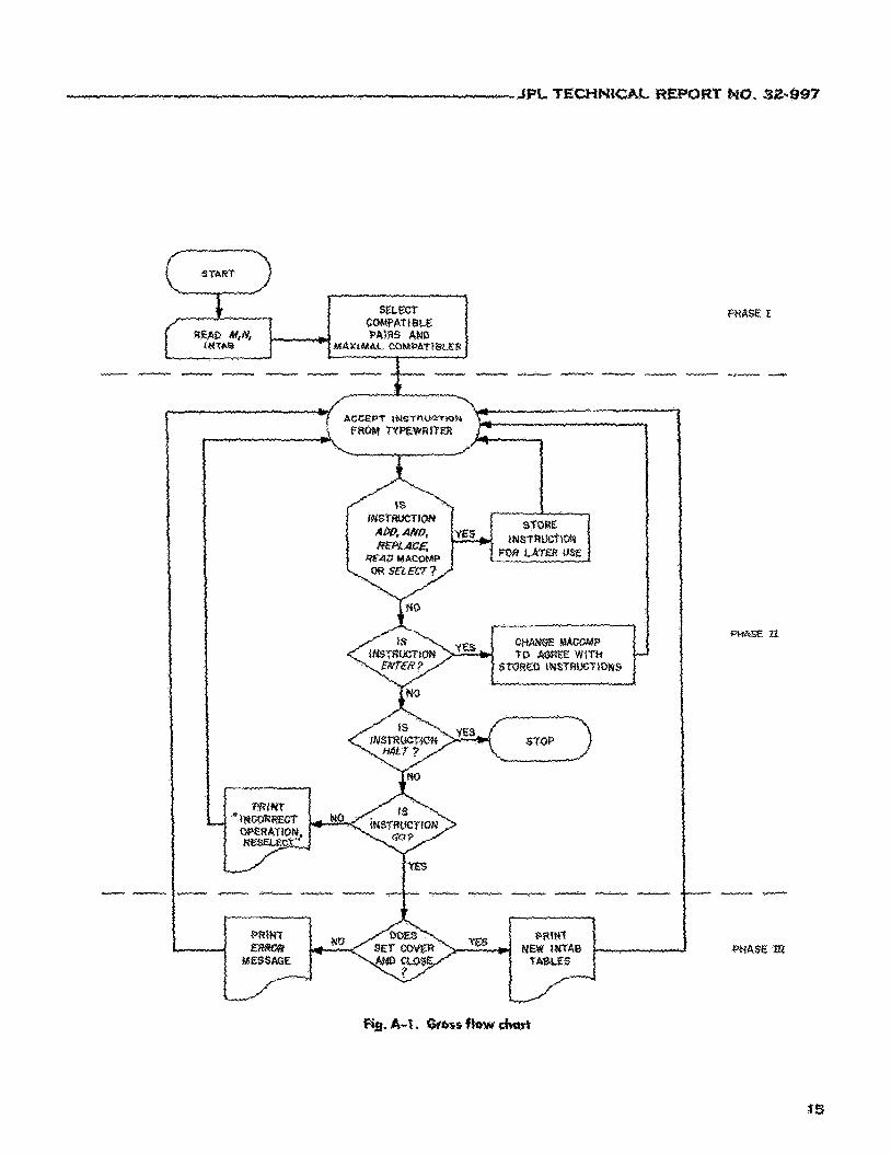
The program is divided into three operational phases: Phase I, 11, and 111. The inputs required for and outputs generated by each phase (Fig. A-1) are as follows:
A. Phase I 1. Input: Data Card Preparation
The Input consists of the information contained in the flow table that represents the sequential machine to be simplged. The format of the input data follows closely the standard format of a sequential 00w table.
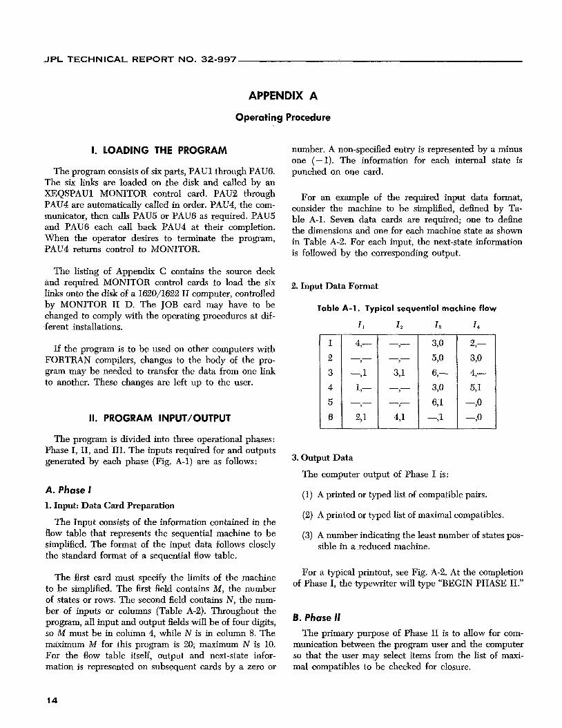
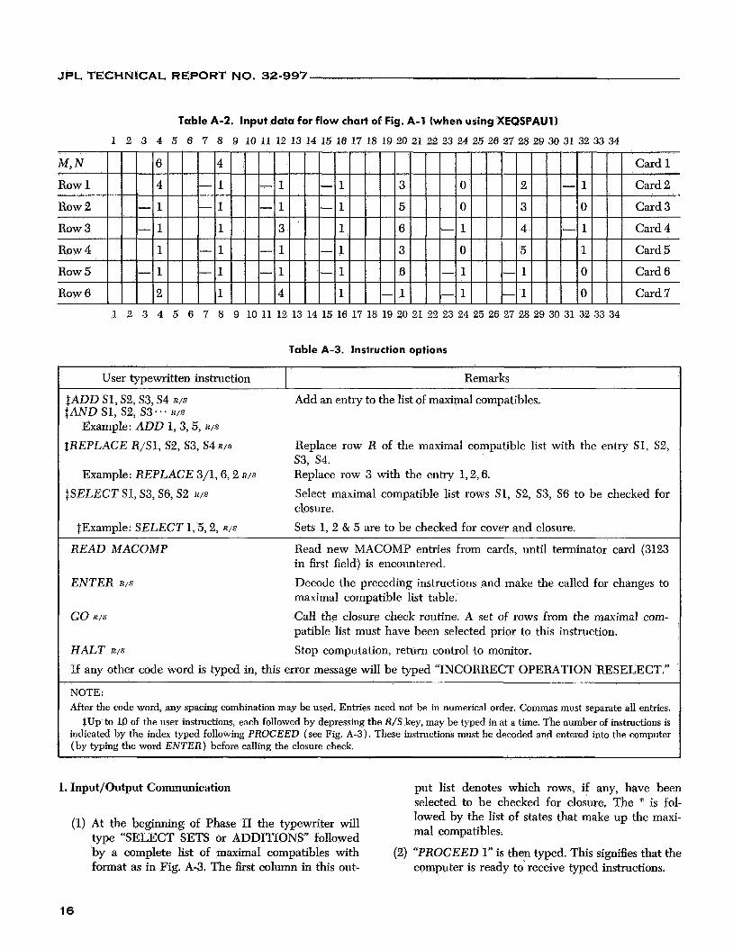
The first card must specify the limits of the machine to be simplified. The first field contains M, the number of states or rows. The second field contains N , the num- ber of inputs or columns (Table A-2). Throughout the program, all input and output fields will be of four digits, so M must be in column 4, while N is in column 8. The maximum M for this program is 20; maximum N is 10. For the flow table itself, output and next-state infor- mation is represented on subsequent cards by a zero or
number. A non-specified entry is represented by a minus one (-1). The information for each internal state is punched on one card.
For an example of the required input data format, consider the machine to be simplified, defined by Ta- ble A-l. Seven data cards are required; one to define the dimensions and one for each machine state as shown in Table A-2. For each input, the next-state information is folIowed by the corresponding output.
2. Input Data Format
Table A-1. Typical sequential machine flow
1, 1 2 1 3 1 4
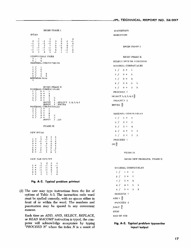
3. Output Data
The computer output of Phase I is:
(1) A printed or typed list of compatible pairs.
(2) A printed or typed list of maximal compatibles.
(3) A number indicating the least number of states pos- sible in a reduced machine.
For a typical printout, see Fig. A-2. At the completion of Phase I, the typewriter will type “BEGIN PHASE 11.”
B. Phase I1 The primary purpose of Phase I1 is to allow for com-
munication between the program user and the computer so that the user may select items from the list of maxi- mal compatibles to be checked for closure.
14
i
JPL TECHNICAL REPORT NO. 32-997
Row 3
Row 4 Row 5
Row 6
Table A-2. Input data for flow chart of Fig. A-1 (when using XEQSPAU11
1 2 3 4 5 6 7 8 9 10 11 12 13 14 15 16 17 18 19 20 21 22 23 24 25 26 27 28 29 30 31 32 33 34
- 1 1 3 1 6 - 1 4 - 1 Card 4
1 - 1 - 1 - 1 3 0 5 1 Card 5
Card 6
2 1 4 1 - 1 - 1 - 1 0 Card 7
- 1 - 1 - 1 - 1 6 - 1 - 1 0
1 2 3 4 5 6 7 8 9 10 11 12 13 14 15 16 17 18 19 20 21 22 23 24 25 26 27 28 29 30 31 32 33 34
Table A-3. Instruction options
I User typewritten instruction I Remarks
$ADD S1, S2,S3, S4 R / S
SAND S1, S2, 53 . ’ . R / S
Example: ADD 1,3,5, R / S
$REPLACE R/Sl, S2, S3, S4 R / S
Add an entry to the list of maximal compatibles.
Replace row R of the maximal compatible list with the entry S1, S2, s3, s4. Replace row 3 with the entry 1,2,6. Select maximal compatible list rows S1, S2, S3, S6 to be checked for closure. Sets 1, 2 & 5 are to be checked for cover and closure.
Example: REPLACE 3/1,6,2 R / S
$SELECT S1, S3, S6, S2 R / S
$Example: SELECT 1,5,2, R / S
READ MACOMP
ENTER R / S
GO R / S
Read new MACOMP entries from cards, until terminator card (3123 in first field) is encountered. Decode the preceding instructions and make the called for changes to maximal compatible list table. Call the closure check routine. A set of rows from the maximal com- patible list must have been selected prior to this instruction. Stop computation, return control to monitor. HALT R / S
If any other code word is typed in, this error message will be typed “INCORRECT OPERATION RESELECT.”
NOTE: After the code word, any spacing combination may be used. Entries need not be in numerical order. Commas must separate all entries.
$Up to 10 of the user instructions, each followed by depressing the R/S key, may be typed in at a time. The number of instructions is indicated by the index typed following PROCEED (see Fig. A-3). These instructions must be decoded and entered into the computer (by typing the word ENTER) before calling the closure check.
1. Input/Output Communication put list denotes which rows, if any, have been selected to be checked for closure. The * is fol- lowed by the list of states that make up the maxi- mal compatibles.
(2) “PROCEED 1” is then typed. This signifies that the computer is ready to. receive typed instructions.
(1) At the beginning of Phase I1 the typewriter will type “SELECT SETS or ADDITIONS” followed by a complete list of maximal compatibles with format as in Fig. A-3. The first column in this out-
16
JPL TECHNICAL REPORT NO. 32-997
BEGIN PHASE I
INTAB
1 2 3 4 4 -1 -1 -1 3 0 2 -1
-1 -1 -1 -1 5 0 3 0 -1 1 3 1 6 -1 4 -1 1 -1 -1 -1 3 0 5 1
-1 -1 - 1 -1 6 1 -1 0 2 1 4 1 - 1 1 - 1 0
COMPATIBLE PAIRS 3 , 5 5 , 6
MAXIMAL COMPATIBLES
1 / 1 2 / 2
5 / 3 5 2 5 2 6
MINIMUM SIZE 5
BEGIN PHASE I1 MAXIMAL COMPATIBLES
1 / 0 % 1 2 / 0 ’ : 2 3 / o * 4 4 / O * 5 6 5 / 0 ’ : 3 5
INPUT 1 ,SELECT 1 , 2 , 3 , 4 , 5 INPUT 2 ,ENTER
MAXIMAL COMPATIBLES 1 / 1 * 1 2 7 2 “ - 2 3 / 3 * 4
5 / 5 * 3 5 4 / 4 % 5 6
INPUT 1 ,GO
PHASE I11
NEW INTAB
1 2 3 4 1 ‘ : 3 -1 5 2 2 * - 1 - 1 4 5 o * o 0 5 0 3 * 1 -1 5 4 0 9 0 0 0 5 4 * 2 3 4 - 1 5 * -1 5 4 3
NEW TAB OUTPUT
1 2 3 4 1 * -1 -1 0 -1 2 * -1 -1 0 0 3 * -1 -1 0 1 4;: 1 1 1 0 5 * 1 1 1 0
Fig. A-2. Typical problem printout
(3) The user may type instructions from the list of options of Table A-3. The instruction code word must be spelled correctly, with no spaces either in front of or within the word. The numbers and punctuation may be spaced in any convenient manner.
Each time an ADD, AND, SELECT, REPLACE, or READ MACOMP instruction is typed, the com- puter will acknowledge acceptance by typing “PROCEED N” where the index N is a count of
t $ XEQSPAUI
EXECUTION
BEGIN PHASE I
BEGIN PHASE I1
SELECT SETS OR ADDITIONS
MAXIMAL COMPATIBLES
1 / o * 1
2 / o * 2
3 / 0 % 4
5 / o * 3 5
4 / O * 5 6
PROCEED 1
SELECT 1, 2, 3,4,5 Ei 5
PROCEED 2
ENTER
MAXIMAL COMPATIBLES
1 / l * 1
2 / 2 * 2
3 / 3 * 4
5 / 5 * 3 5
4 / 4 * 5 6
PROCEED 1
GO 2
PHASE I11
BEGIN NEW PROBLEM, PHASE I1
MAXIMAL COMPATIBLES
1 / 1 * 1
2 / 2 ” 2
3 / 3 * 4
5 / 5 * 3 5
4 / 4 * 5 6
PROCEED 1
A D D 1 g PROCEED 2
HALT -$ STOP
END OF JOB
Fig. A-3. Typical problem typewriter input/output
1 7
JPL TECHNICAL REPORT NO. 32-997
1* 2”
3* o* 4* 5*
how many instructions have been typed. The five above listed instructions are stored on the disk to be decoded later.
(4) Use of the ENTER instruction. After the desired additions or selections axe made, type the word ENTER. The desired modifications to or selections of maximal compatible entries will then be made.
3 -1 5 2 -1 -1 4 5
0 * 0 0 5 0 1 -1 5 4 0 0 0 5 2 3 4 -1
-1 5 4 3
A printout of a new maximal compatible list will result, indicating the selections or additions made.
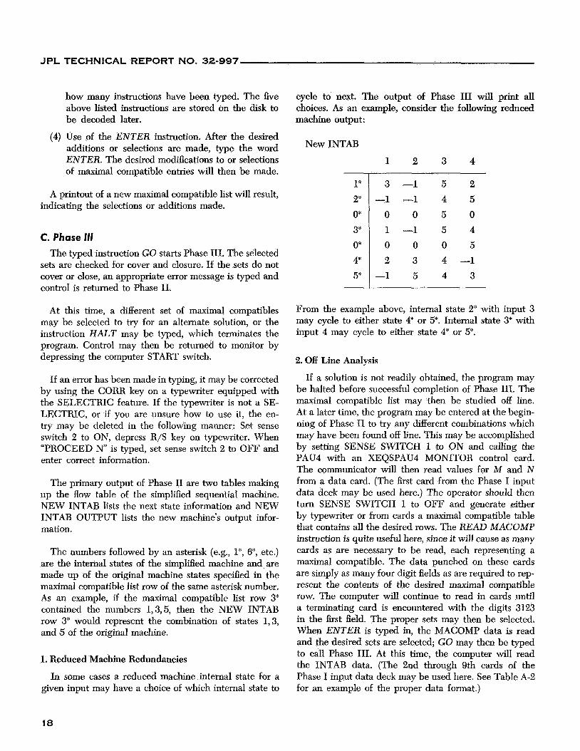
C. Phase 111 The typed instruction GO starts Phase 111. The selected
sets are checked for cover and closure. If the sets do not cover or close, an appropriate error message is typed and control is returned to Phase 11.
cycle to next. The output of Phase I11 will print all choices. As an example, consider the following reduced machine output :
New INTAB
At this time, a different set of maximal compatibles may be selected to try for an alternate solution, or the instruction HALT may be typed, which terminates the program. Control may then be returned to monitor by depressing the computer START switch.
From the example above, internal state 2”: with input 3 may cycle to either state 4“ or 5*. Internal state 3* with input 4 may cycle to either state 4* 01 5*.
2. Off Line Analysis
If an error has been made in typing, it may be corrected by using the CORR key on a typewriter equipped with the SELECTRIC feature. If the typewriter is not a SE- LECTRIC, or if you are unsure how to use it, the en- try may be deleted in the following manner: Set sense switch 2 to ON, depress R/S key on typewriter. When “PROCEED N” is typed, set sense switch 2 to OFF and enter correct information.
The primary output of Phase I1 are two tables making up the Bow tabIe of the simplified sequential machine. NEW INTAB lists the next state information and NEW INTAB OUTPUT lists the new machine’s output infor- mation.
The numbers followed by an asterisk (e.g., 1*, 6*, etc.) are the internal states of the simplified machine and are made up of the original machine states specified in the maximal compatible list row of the same asterisk number. As an example, if the maximal compatible list row 3* contained the numbers 1,3,5, then the NEW INTAB row 3* would represent the combination of states 1,3, and 5 of the original machine.
1. Reduced Machine Redundancies
In some cases a reduced machine internal state for a given input may have a choice of which internal state to
If a solution is not readily obtained, the program may be halted before successful completion of Phase 111. The maximal compatible list may then be studied off line. At a later time, the program may be entered at the begin- ning of Phase I1 to try any different combinations which may have been found off line. This may be accomplished by setting SENSE SWITCH 1 to ON and calling the PAU4 with an XEQSPAU4 MONITOR control card. The communicator will then read values for M and N from a data card. (The first card from the Phase I input data deck may be used here.) The operator should then turn SENSE SWITCH 1 to OFF and generate either by typewriter or from cards a maximal compatible table that contains all the desired rows. The READ MACOMP instruction is quite useful here, since it will cause as many cards as are necessary to be read, each representing a maximal compatible. The data punched on these cards are simply as many four digit fields as are required to rep- resent the contents of the desired maximal compatible row. The computer will continue to read in cards until a terminating card is encountered with the digits 3123 in the first field. The proper sets may then be selected. When ENTER is typed in, the MACOMP data is read and the desired sets are selected; GO may then be typed to call Phase 111. At this time, the computer will read the INTAB data. (The 2nd through 9th cards of the Phase I input data deck may be used here. See Table A-2 for an example of the proper data format.)
J P L TECHNICAL REPORT NO. 32-997
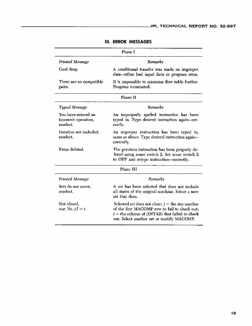
111. ERROR MESSAGES
Phase I
Printed Message R m r k s
Goof Stop. A conditional transfer was made on improper data-either bad input data or program error.
There are no compatible pairs. Program terminated.
It is impossible to minimize flow table further.
Phase I1
Typed Message Remarks
You have entered an incorrect operation, reselect. rectly.
Iteration not included, reselect.
An improperly spelled instruction has been typed in. Type desired instruction again-cor-
An improper instruction has been typed in, same as above. Type desired instruction again- correctly.
Error deleted. The previous instruction has been properly de- leted using sense switch 2. Set sense switch 2 to OFF and retype instruction-correctly.
Phase I11
Printed Message Remarks
Sets do not cover, reselect.
A set has been selected that does not include all states of the original machine. Select a new set that does.
Not closed, star No. i 1 = i.
Selected set does not close: i = the star number of the h s t MACOMP row to fail to check out; i = the column of (INTAB) that failed to check out. Select another set or modify MACOMP.
1 9

JPL’TECHNICAL REPORT NO. 32-997
APPENDIX B
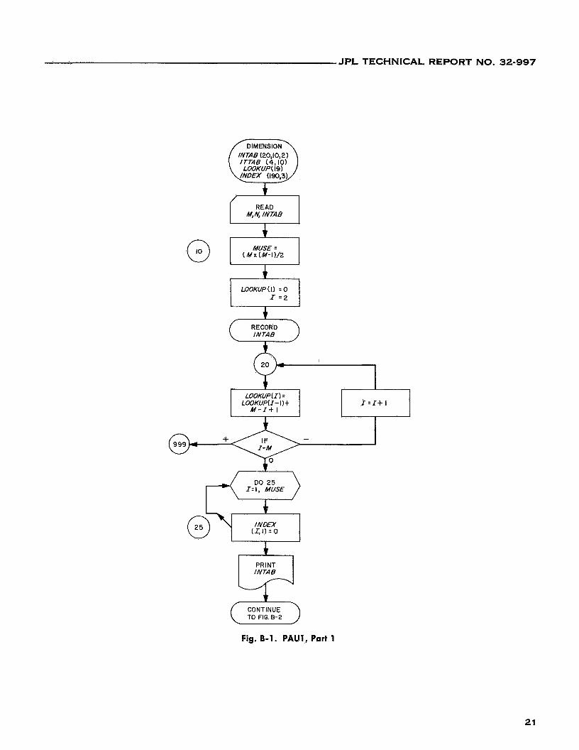
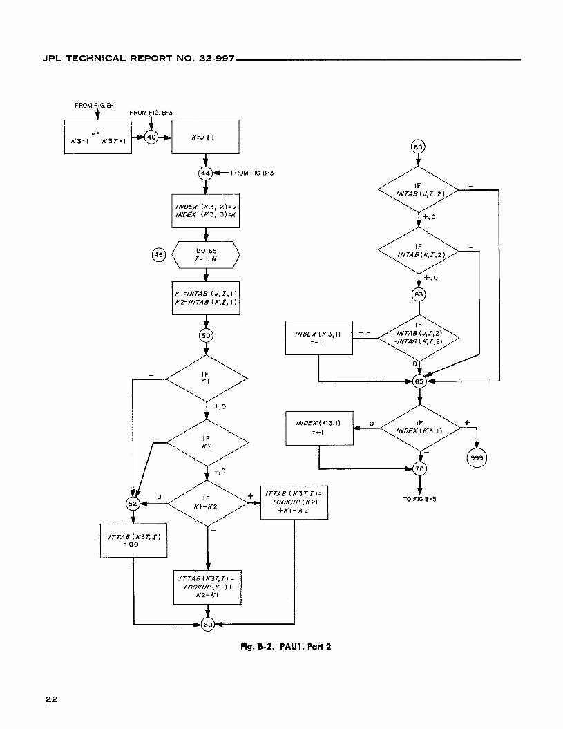
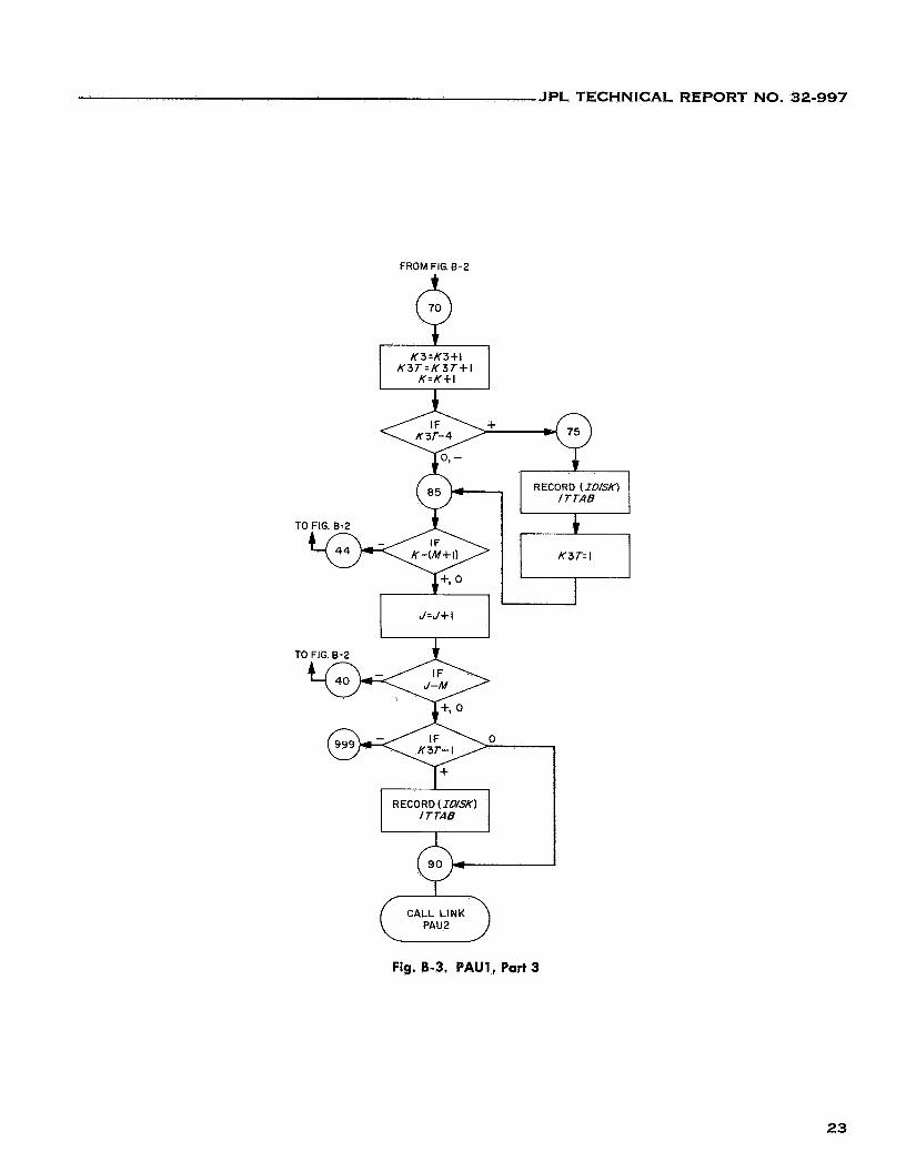
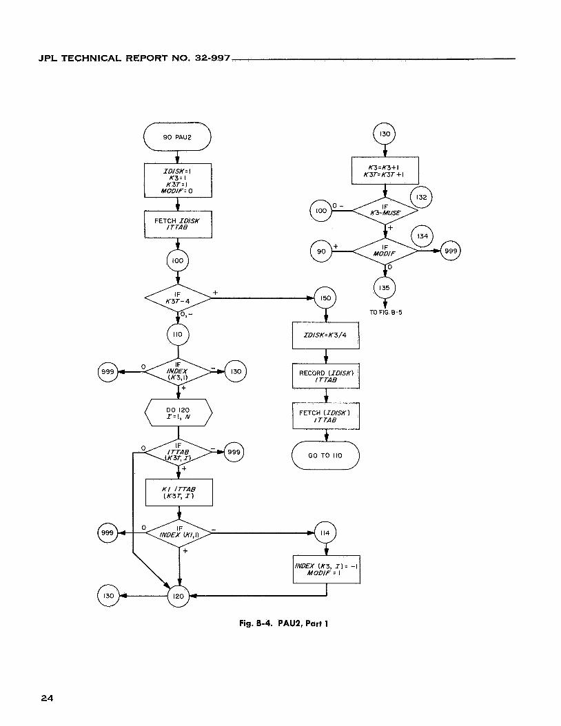
Program Flow Diagrams
Figures B-1 through B-18 are the flow diagrams for this program.
20
JPL TECHNICAL REPORT NO. 32-997
/DIMENSION\ INTAB (20,10,2) ITTAB (4,101 LOOKUP( 19)
(-1 M,4 INTAB
Fig. B-1. PAUI, Part 1
21
JPL TECHNICAL REPORT NO. 32-997
FROM FIG. B-1 FROM FIG. 8-3
K= J+ 1 K 3 - I K 3 T : I
& FROM FIG. 8-3
+ INDEX ( K 3 , 2)=J INDEX ( K 3 , 3 ) :K
t DO 65
KI=/NTAB ( J , I , I) K2=/NTAB ( K J , I)
+ TO FIG.B-3
Fig. B-2. PAU1, Part 2
22
JPL TECHNICAL REPORT NO. 32-997
TO FIG. E-2
9
FROM FIG. 8-2
TO FIG. 8-2
0
RECORD (rD/sK) ITTAB
Fig. B-3. PAUl, Part 3
23
JPL TECHNICAL REPORT NO. 32-997
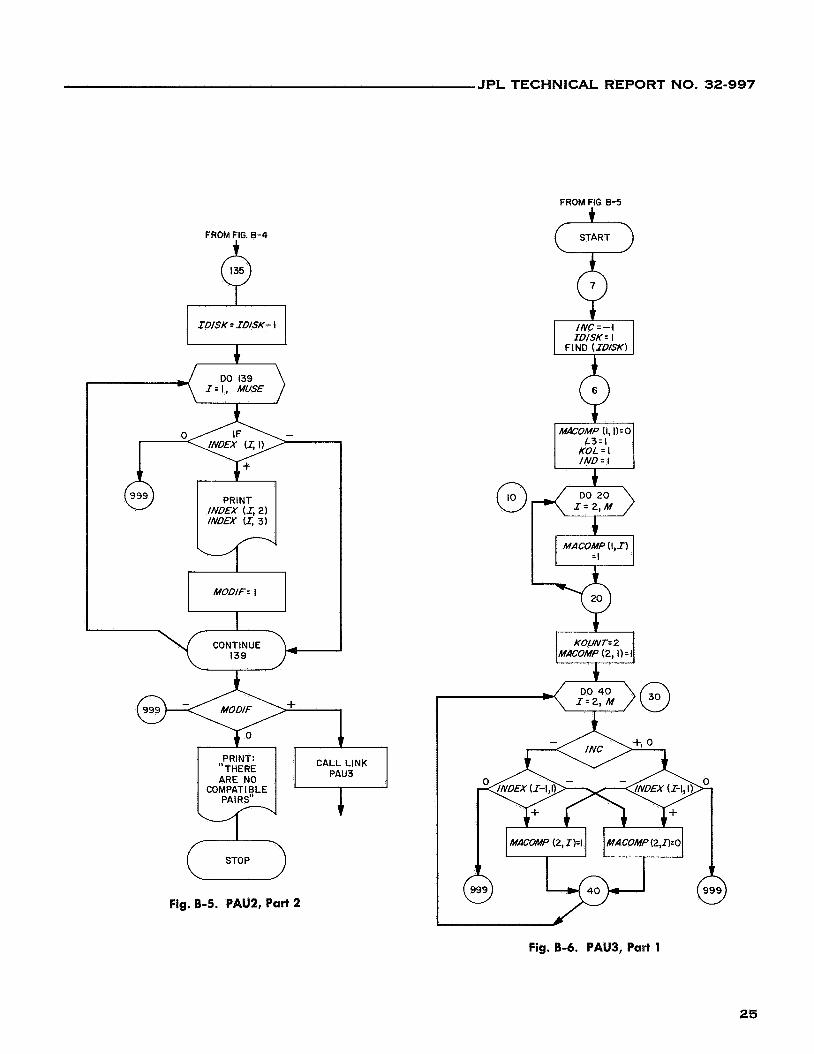
Fig. 8-4. PAU2, Part 1
24
JPL TECHNICAL REPORT NO. 32-997
FROM FIG. B-5
FROM FIG. 8-4
IDISK = IDISK- I
PRINT INDEX (I, 2) INDEX U, 3)
MODIF. I
I CONTINUE
I39
I
CALL LINK PAUJ
PRINT: "THERE ARE NO
COMPATIBLE PAIRS"
I
STOP
c START
Fig. 8-5. PAU2, Part 2
Fig. 8-6. PAU3, Part 1
25
JPL TECHNICAL REPORT NO. 32-997
FROM FIG. B-6
CONTINUED 0 KOUNT I = KOUN T
KOL + I
DO 100 J: I , KOUNT I
I
KOUN T + I
IND: LOOKUP (KOL)
6
t r = t , M DO 90
--yJ-<T) CONTINUE
TO FIG 8-8
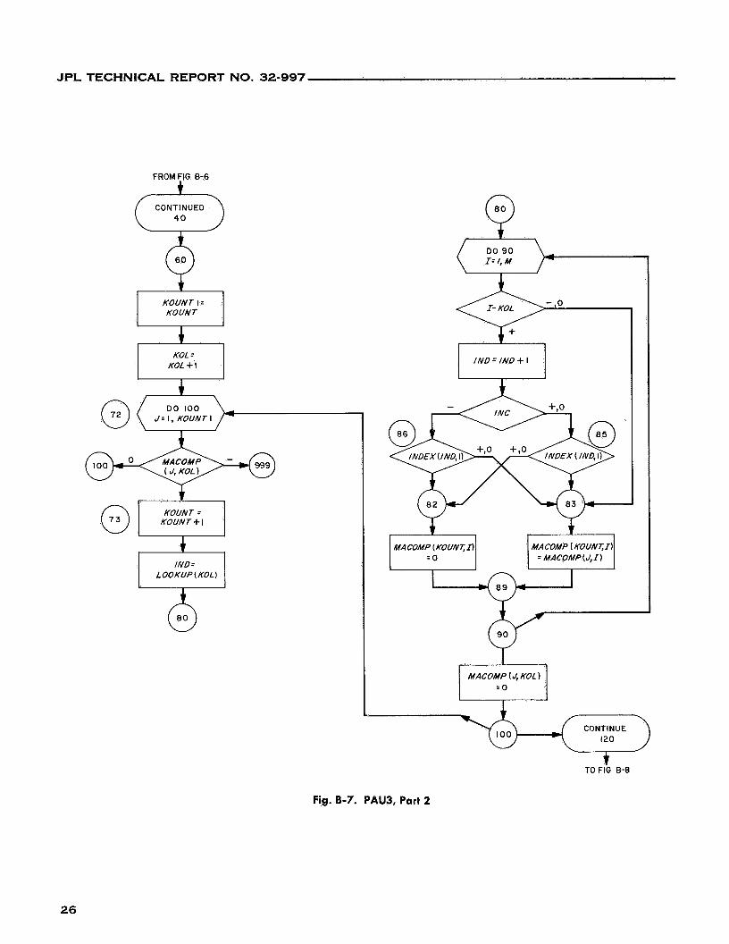
Fig. 8-7. PAU3, Part 2
26
JPL TECHNICAL REPORT NO. 32-997
FROM FIG 0-7 (:.> CONTINUED
DO 200 JC = I, KOUNT
KOUN T = KOUN T- I
t TO FIG B-9
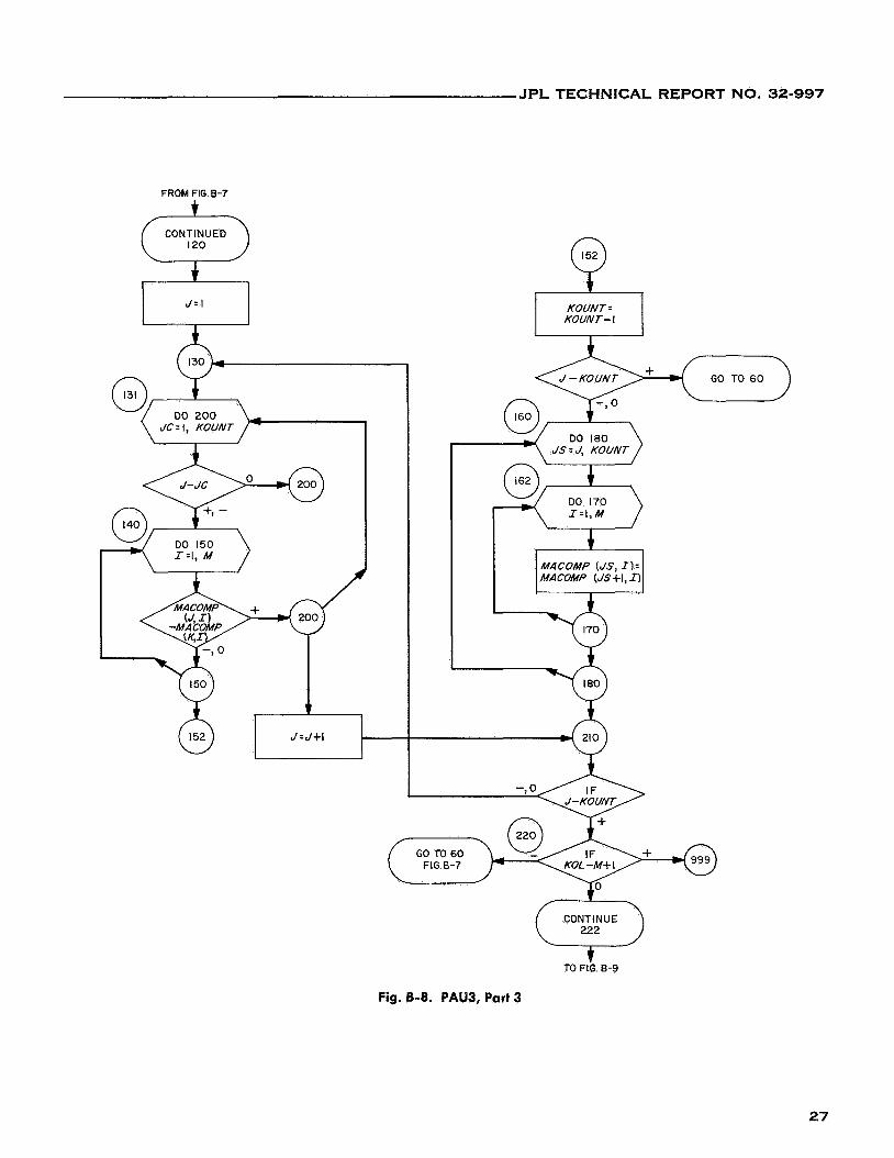
Fig. B-8. PAUB, Part 3
27
JPL TECHNICAL REPORT NO. 32-997
FROM FIG. B-8
CONTINUE
I I =Il+l PRINT: "ERROR
.) SET"
ISET ( I l l - I
Q " MINI MUM
RECORD MACOhff
IDISK. 0 KOUNT=MACS/Z
MACSIZ = KOUNT
GO TO 6 FIG. B-6
FRINT:
STOP"
STOP
28
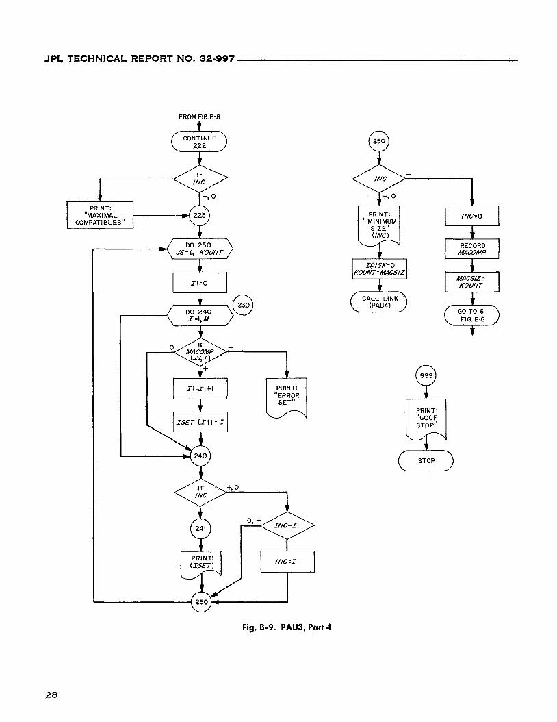
Fig. 8-9. PAU3, Part 4
JPL TECHNICAL REPORT NO. 32-997
START (7 ON OFF
READ M N
I t
KOUNT.0 I N = I
IDISK=l
b TYPE:
SWITCH I "SET SENSE
OFF"
"SELECT SETS OR ADDITIONS"
FIND ( IDISKf
0
i ID/SK= I IN:O
1 t I FETCH I MACOMP I
SET MACOMP M+I COLUMN
PRi NT AND
I I
SET 1 NTAKE
TO 0
4 TYPE
"PROCEED ( IDISK~"
TO FIG B-ll
Fig. B-10. PAU4, Part 1
29
JPL TECHNICAL REPORT NO. 32-997
GO TO 50 PRINT
( INTAKE)
+ TO FIG 6-10
5- RECORD I D I S K
Fig. B-1 1. PAU4, Part 2
30
JPL TECHNICAL REPORT NO. 32-997
START 9- XDfG: 7000 KT=IDfSK IDfSK= I
FETCH fNTAKE
+ +,- r 1
I A DD= KA DD ( ID/SK - I )
TO FIG. 8-13
1
f N TA KE u I I K0UN;;KOUN T
SET MACOMP ROW (KOUNT)TOZ€RO
DO 508
KI=fNTAB ( J ) f N TA KE (J = 0
MACOMP ( KOUNT, K I ) = I
Fig. 8-12. PAUS, Part 1
3 1
JPL TECHNICAL REPORT NO. 32-997
FROM FIG 6-12
W
TO FIG. 6-15
Fig. 8-13. PAUS, Part 2
32
JPL TECHNICAL REPORT NO. 32-997
FROM FIG. 8-13 6
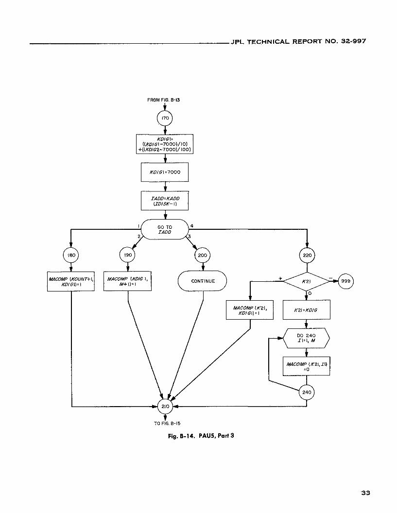
Fig. 8-14. PAUS, Part 3
33
JPL TECHNICAL REPORT NO. 32-997
IDISK 17
'0 FIG. 8-12
READ INTAB
.c+
I I K22=K22+1
TO FIG 8-12
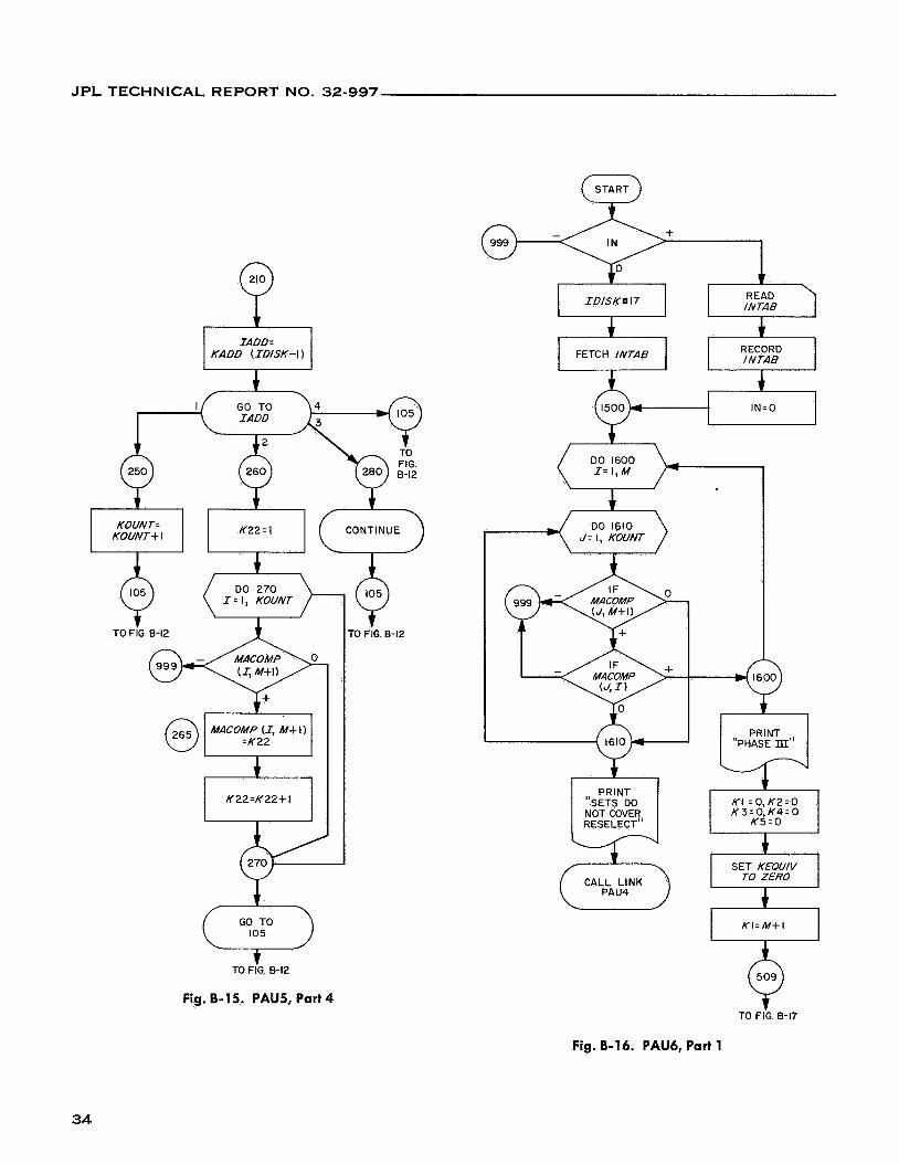
Fig. B-15. PAUS, Part 4
FETCH INTAB i l
DO 1600 I = I , M
DO 1610 J = I, KOUNT
+l PRINT
(Fj CALL LINK
PRINT "PHASE m"
KI = 0 , K 2 = 0 K 3 = 0, K4 = 0
K5.0
SET KEQUI V TO ZERO i KI=M+l
lo' TO FIG 8-17
Fig. 8-16. PAU6, Part 1
34
J P L TECHNICAL REPORT NO. 32-997
FROM FIG B-16
SET KTEMP TO ZERO
4 K 5 H = 0 MARK=O
MATCH -- 0 K 5 H = 0
K5HT= 0
.) DO 605 page 36
step 605 K 2 = I, KOUNT
I
K 5 = K 5 H T +I
K5H=O K 5 L z K 5 I(@)
MACOMP(K2, M+I)
KSTAR= KEQUIV(K5, N + I )
DO 600 Page 36 I= I, N Step 600
I
~ (KSTAR, 1)z - I
TO FIG 8-18
K I = I , M
INTAB (K/ , I, I 1 I
KOU T (KSTA R, I ) = INTAB ( Kl, I, 2 )
l-----l MARK= I
TO i l G . 9-18
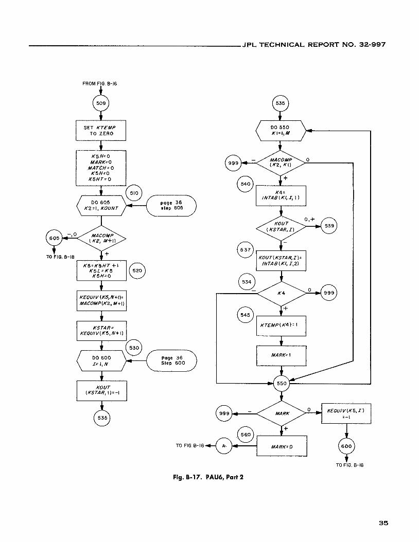
Fig. B-17. PAU6, Part 2
35
JPL TECHNICAL REPORT NO. 32-997
FROM FIG 8-17
DO 570 KI= I , M
MATCH+ I
K€QUlV ( K 5 , I) =MACOMP (K22, M+I)
K5=K5+1
~
PRINT:
[MACOMP "NOT CLOSED"
(K2, M+I)] *[I]
K5H= MATCH
CALL LINK + K5=K5L
( PAU4 ) MATCH :O
SET KTEMP TO ZERO
Page 35 Step 530
K5H T = K 5H T +K5H
Page 35 Step 510
PRINT:
( K€QU I/) (KOUT)
"NEW INTAB"
PRINT: "START NEW
PROBLEM;, PHASE II
CALL L INK
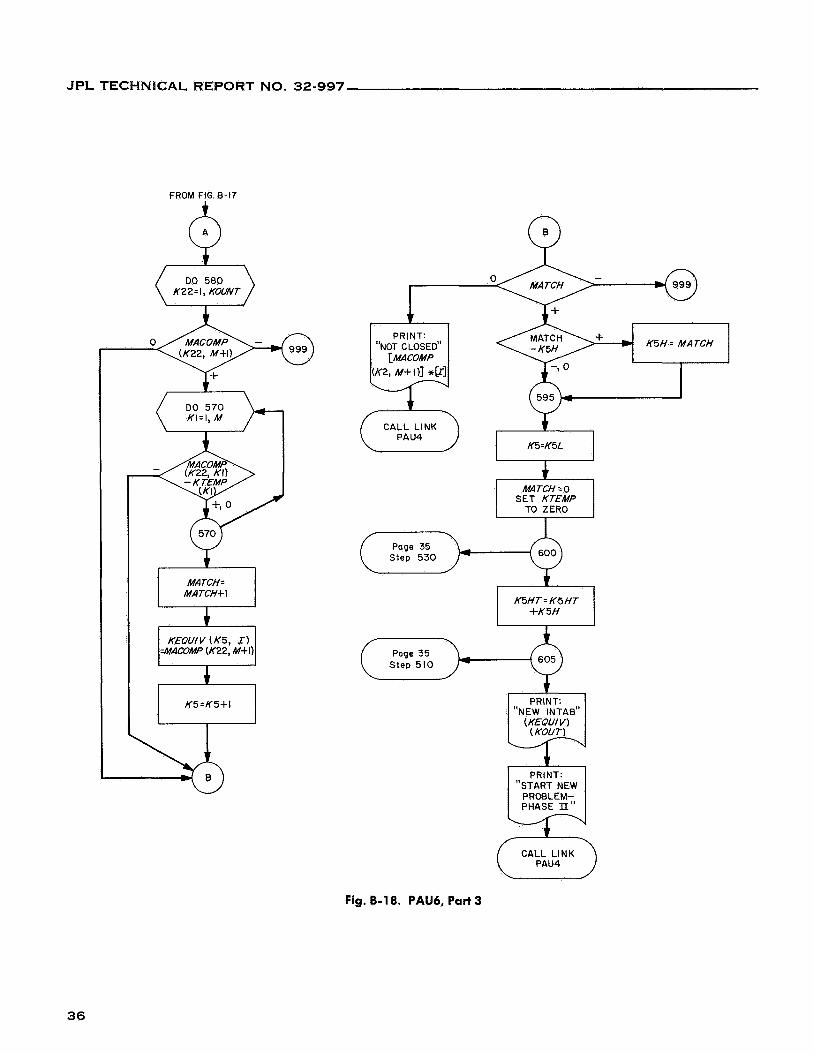
Fig. B-18. PAU6, Part 3
36

JPL TECHNICAL REPORT NO. 32-997
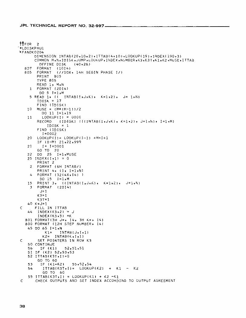
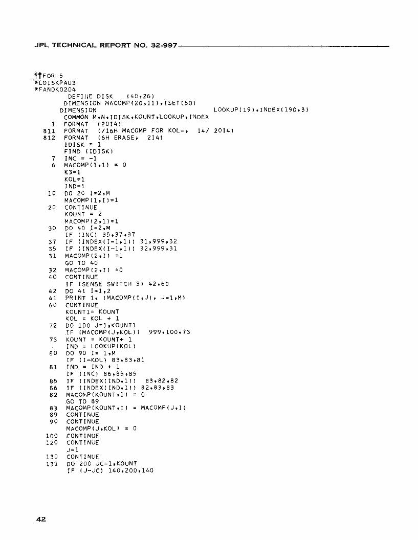
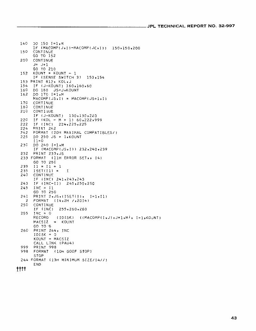
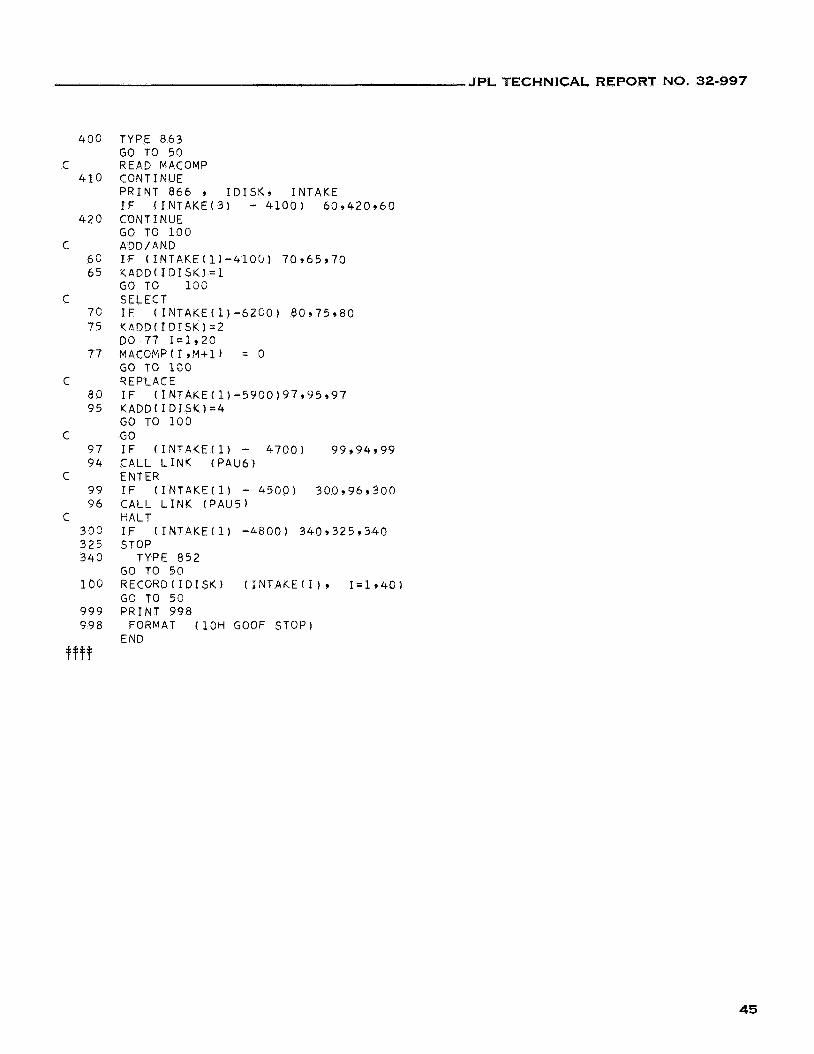
APPENDIX C
Program Listing
37
JPL TECHNICAL REPORT NO. 32-997
TTFOR 2 * L D I S K P A U l '* FANDK0204
DIMENSION I N T A B ~ 2 0 ~ 1 0 ~ 2 ~ ~ I T T A B ~ 4 ~ l O ~ ~ L O O K U P ~ l 9 ~ ~ I ~ D E X ~ l 9 0 ~ 3 ~ COMMCN M , N , I D I S & , J U M P , L O U K U P 9 I ~ ~ E X ~ ~ U M 6 E R 9 & 3 9 K 3 T , ~ l 9 K 2 , M U S E , I T T A a
DEFINE D I S K ( 4 0 9 2 6 ) 8 0 7 FORMAT ( 1 0 1 4 ) 8 0 5 FORMAT ( / / l o x , 14H BEGIN PHASE I/)
P R I N T 805 TYPE 8 6 5 READ 1, M9N
DO 5 I = l , M 1 FORMAT ( 2 0 1 4 )
5 READ 1, ( ( I N T A B ( I , J , K ) , K = 1 , 2 ) 9 J = 1 9 N ) I D I S k = 1 7 F I N D ( I D I S K )
1 0 MUSE = ( M * ( M - 1 ) ) / 2
11 LOOKUP( I ) = 0 0 0 0 DO 11 1 ~ 1 9 1 9
RECORD ( I D I S K ) ( ( ( I N T A B ( I , J , K ) , K = 1 9 2 ) , J=l,N)r I = 1 9 M )
F I N D ( I D I S K ) I D I S K = 1
I = 0 0 0 2 2 0 L O O K U P ( I ) = LOOKUP(1-11 + M - I + l
I F ( I - M ) 21922 ,999 2 1 I = I + O O O l
GO TO 2 0 2 2 DO 2 5 I= l ,MUSE 25 I N D E X ( I 9 1 ) = 0
PRINT 2 2 FORMAT ( 6 H I N T A B / )
PRINT 4 9 ( 1 , I = l g N ) 4 FORMAT ( 3 2 ( 4 X 9 1 4 ) 1
DO 1 5 I = l r M 1 5 P R I N T 39 ( ( I N T A B ( I , J , L ) , K = 1 9 2 ) , J = l , N )
3 FORMAT ( 2 0 1 4 ) J = 1
K3= 1 K 3 T = 1
4 0 K = J + l C F I L L I N I T T A B
44 I M D E X ( K 3 9 2 ) = J I N D E X ( K 3 9 3 ) =K
8 0 1 FORMAT(3H J = , 14 , 3H &=, 1 4 ) 8 0 0 F O R M A T ( 1 2 H STEP NUMBER, 14)
4 5 DO 6 5 1=1,N K 1 = I N T A B ( J , I , l )
K2= I N T A B ( K 9 1 , l ) C SET POINTERS I N RON K 3
5 0 CONTINdE 5 6 I F ( K 1 ) 5 2 , 5 1 9 5 1 5 1 I F ( K 2 ) 52 ,53353 52 I T T A R ( K 3 T , I ) = O
5 3 I F ( K l - K 2 ) 5 5 , 5 2 9 5 4 5 4 I T T A B ( K 3 T , I ) = LOOKUP(k2 ) + K 1 - K Z
55 I T T A B ( K 3 T , I ) = LOOKUP(K1) + K 2 - K 1
GO TG 6 0
GO TO 6 0
C CHECK OUTPUTS AN2 SET INDEX ACCORDIFJS TO OUTPUT AGREEMENT
38
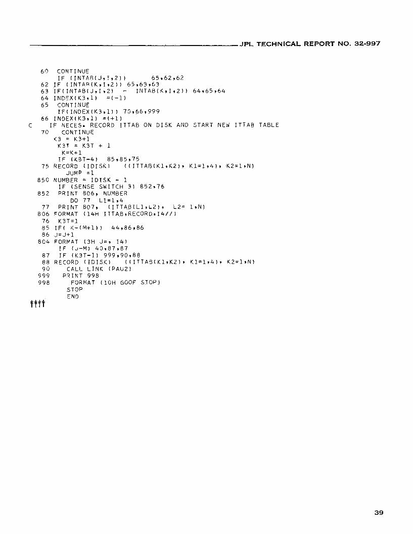
JPL TECHNICAL REPORT NO. 32-997
6Q CONTINUE I F ( I N T A B ( J 9 1 9 2 ) ) 6 5 9 6 2 962
6 2 I F ( I N T A R ( K 9 1 9 2 ) ) 65 ,63963 63 I F ( I N T A B ( J 9 1 9 2 1 - I N T A B ( K 9 1 9 2 ) ) 6 4 9 6 5 9 6 4 6 4 I N D E X ( K 3 9 1 ) = ( - 1 1 6 5 CONTINUE
6 6 I N D E X ( K 3 t l ) = ( + 1 )
7 0 CONTINUE
I F ( I P i D E X ( K 3 r l ) ) 7 0 , 6 6 9 9 9 9
C I F NECES. RECORD I T T A E ON D I S K AND START NEW I T T A B TABLE
Y3 = K 3 + 1
K=K+1 K3T = K3T + 1
I F ( K S T - 4 ) 85 ,85975 75 RECORD ( I D I S K ) ( ( I T T A B ( K l , K 2 ) * K 1 = 1 , 4 ) , K 2 = 1 * N )
JUMP =1 8 5 0 NUMBER = I D I S K - 1
8 5 2 PRINT 506, NUMBER I F (SENSE SWITCH 3 ) 8 5 2 9 7 6
00 7 7 L 1 = 1 9 4 7 7 PRINT 807, ( I T T A B ( L 1 9 L 2 ) g L2' 1,N)
8 0 6 FORMAT ( 1 4 H I T T A B , R E C O R D * I 4 / / ) 7 6 K 3 T = 1
8 6 J = J + l 8 5 I F ( K-(M+1)) 4 4 9 8 6 9 8 6
8 0 4 FORMAT (3H J = r 1 4 ) I F ( J - M ) 4 0 , 8 7 9 8 7
8 7 I F ( K 3 T - 1 ) 9 9 9 , 3 0 9 8 8 8 8 RECORD ( I D I S K ) ( ( I T T A B ( K 1 9 K 2 ) 9 K 1 = 1 9 4 ) 9 K 2 = 1 9 N ) 9 0 C A L L L I N K ( P A U 2 )
9 9 9 PRINT 9 9 8 9 9 8 FORMAT (10H GOOF STOP)
STOP END
t f f f
39
JPL TECHNICAL REPORT NO. 32-997
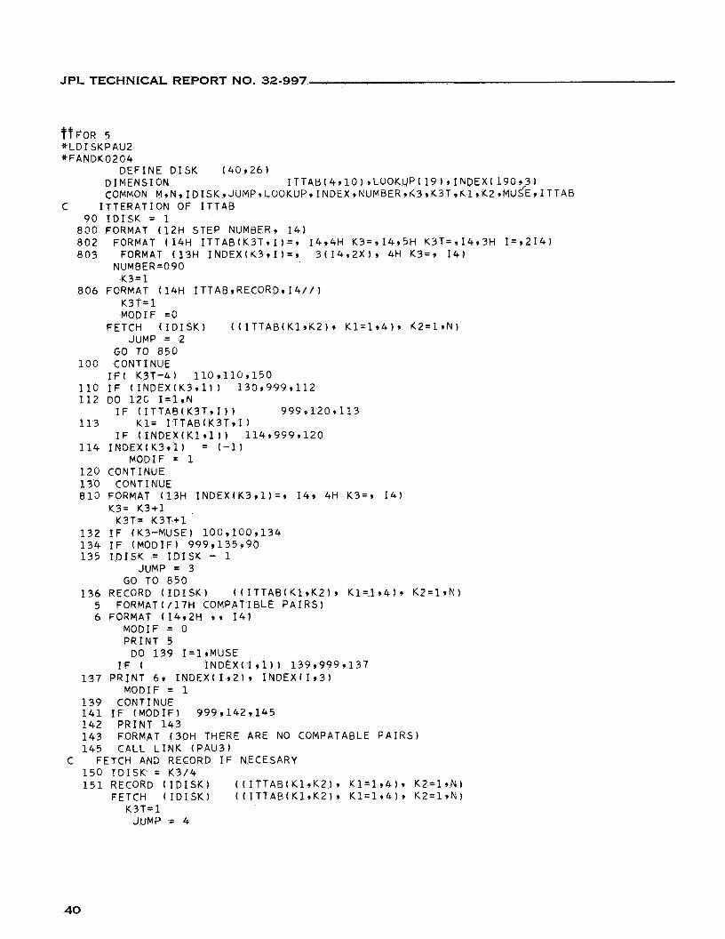
VFOR 5 *LDISKPAU2 sFANDK0204
DEFINE D I S K ( 4 0 9 2 6 ) D I MENS1 ON I T T A B ( 4 , 1 0 ) , L O O K 4 P ( 1 9 ) , I N ~ E X ( 1 9 0 , c 3 ) COMMON M,N,IDISK,JUMP,LOOKUP,INDEX,NUMaER,~3,K3T,~l,K2~MUSE,ITTAB
C ITTERATION OF I T T A B 90 I D I S K = 1
8 0 0 FORMAT ( 1 2 H STEP NUMBER, 1 4 ) 8 0 2 FORMAT 114H I T T A B ( K 3 T , I ) = , I 4 9 4 H K 3 = 9 1 4 9 5 H K 3 T = r I 4 1 3 H I = , 2 1 4 ) 8 0 3 FORMAT ( 1 3 H I N D E X ( K 3 r I ) = , 3 ( 1 4 , 2 X ) , 4H K3=, 1 4 )
NUMBER=090 K 3 = 1
K 3 T = 1 MODIF = O
8 0 6 FORMAT ( 1 4 H ITTAB,RECORD,14//)
FETCH ( I D I S K ) ( ( I T T A B ( K l , K Z ) , K1=1 ,4 ) , K 2 = 1 9 N ) JUMP = 2
GO TO 850 10C CONTINUE
110 I F ( I N D E X ( K 3 , l ) ) 1 3 0 , 9 9 9 r 1 1 2 1 1 2 DO 12C I = l , N
1 1 3 K 1 = I T T A B ( K 3 T 9 1 )
114 I N D E X ( K 3 9 1 ) = (-1) MODIF = 1
1 2 0 CONTINUE 1 3 0 CONTINUE
I F ( K 3 T - 4 ) 1 1 0 ~ 1 1 0 ~ 1 5 0
I F ( I T T A B ( K 3 T , I ) ) 999,120,113
I F ( I N D E X ( K 1 , l ) ) 114,999,120
810 FORMAT ( 1 3 H I N D E X ( K 3 , 1 ) = , 14, 4H K 3 = r 1 4 ) Y3= K 3 + 1
K3T= K 3 T + 1 1 3 2 I F (K3-MUSE) 1 0 0 ~ 1 0 0 ~ 1 3 4 1 3 4 I F ( M O D I F ) 9 9 9 , 1 3 5 9 9 0 1 3 5 I D I S K = I D I S K - 1
GO TO 8 5 0 JUMP = 3
1 3 6 RECORD ( I D I S K ) ( ( I T T A B ( Y l , K 2 ) , K 1 = 1 , 4 ) , K 2 = l r N ) 5 FORMAT(/17H COMPATIBLE P A I R S ) 6 FORMAT ( I 4 r 2 H 9 , 1 4 )
MODIF = 0 PRINT 5
DO 1 3 9 I= l ,MUSE I F ( I N D E X ( I 9 1 ) ) 1 3 9 , 9 9 9 9 1 3 7
1 3 7 PRINT 6 9 I N D E X ( I I Z ) , I N D E X ( I 9 3 )
1 3 9 CONTINUE 141 I F (MODIF) 999,142,145 1 4 2 PRINT 1 4 3 1 4 3 FORMAT ( 3 0 H THERE ARE NO COMPATABLE P A I R S ) 1 4 5 CALL L I N K ( P A U 3 )
1 5 0 I D I S K = K 3 / 4
MODIF = 1
C FETCH AND RECORD I F NECESARY
1 5 1 RECORD ( I D I S K ) ( ( I T T A B ( K l v K 2 ) y K 1 = 1 , 4 ) 9 K2=1,N) FETCH ( I D I S K ) ( ( I T T A B ( K l , K Z ) , K 1 = 1 9 4 ) 9 K 2 = 1 9 N )
K 3 T = 1 JUMP = 4
40
JPL TECHNICAL REPORT NO. 32-997
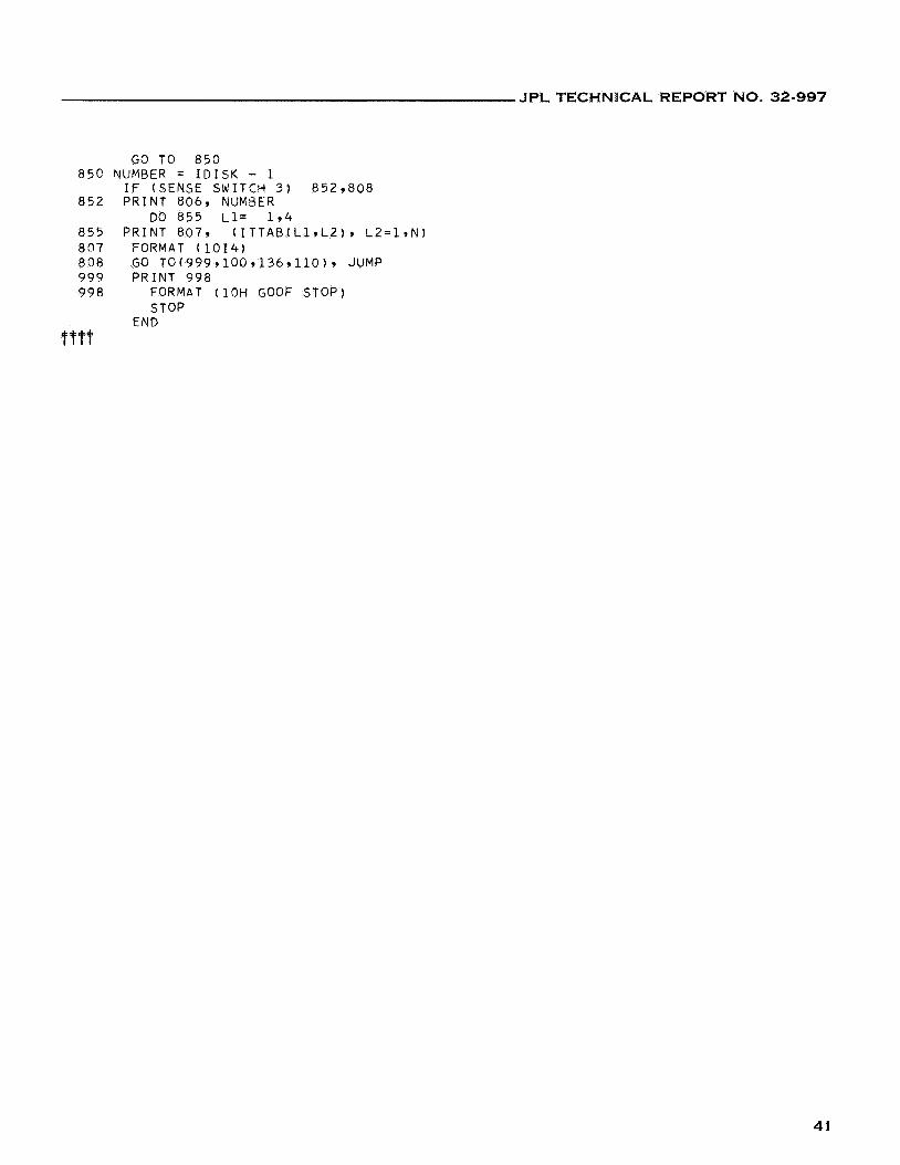
GO TO 850 85'2 NUMBER = IDISK - 1
852 PRINT 806, NUMBER
855 PRINT 807, (ITTAB(Ll,LZ), L2=lrN) 807 FORMAT (1014) 808 GO T0(999r1009136r110), JUMP 999 PRINT 998 998 FORMAT (10H GOOF STOP)
IF (SENSE SWITCH 3) 852,808
DO 855 L1= 1 9 4
STOP END
ifttt
41
JPL TECHNICAL REPORT NO. 32-997
L f t F O R 5 *LDISKPAU3 *FANDK0204
D E F I I I E D I S K ( 4 0 9 2 6 ) DIMENSION M A C O M P ( 2 0 , 1 1 ) 9 I S E T ( 5 0 )
DIMENSION L G O K U P ( 1 9 ) , I N D E X ( 1 9 0 , 3 )
1 811 812
7 6
10
20
30
37 3 5 3 1
32 40
4 2 4 1 6 0
72
73
8 0
8 1
8 5 8 6 8 2
83 89 90
100 1 2 0
1 3 0 1 3 1
COMMON M ~ N ~ I D I S K 9 K O U N T ~ L O O K U P ~ I N D E X FORMAT ( 2 0 1 4 ) FORMAT ( / 1 6 H MACOMP FOR KOL=, 14/ 2 0 1 4 ) FORMAT ( 6 H ERASE9 214) I D I S K = 1 F I N D ( I D I S K ) I N C = -1 MACOMP(191) = 0 K 3 = 1 K O L = l I N D = l DO 2C I = 2 9 M M A C O M P ( l , I ) = l CONTINUE KOUNT = 2 KACOYP ( 2 9 1 1 =1 DO 40 I = 2 9 M I F (INC) 3 5 9 3 7 9 3 7 I F ( I N D E X ( 1 - 1 9 1 ) ) 3 1 , 9 9 9 9 3 2 I F ( I N D E X ( 1 - 1 9 1 ) ) 3 2 , 9 9 9 9 3 1 MACOMP ( 2 9 I 1 =1 GO TO 40 MPCOVP ( 2 9 I 1 =o CONTINUE I F (SENSE SWITCH 3 ) 4 2 9 6 0 DO 41 I = 1 , 2 P R I N T 1, (MACOMP(I,J), J=1,M) CONTINUE KOUNTl= KOUNT KOL = KOL + 1 DO 100 J = l * K O U N T l I F (MACGMP(J9KOL)) 9999100973 KOUNT = KOUNT+ 1 I N D = LOOKUP(K0L) DO 90 I= 1 9 M
I F ( I - K O L ) 8 3 9 8 3 9 8 1 I N 0 = I N D + 1 I F ( I N C ) 86 ,85985 I F ( I N D E X ( I N D 9 1 ) ) 8 3 9 8 2 9 8 2 I F ( I N D E X ( I N D 9 1 ) ) 8 2 9 8 3 9 8 3 YACOPiP (KOUNT 9 I 1 = 0 GO TO 89 MACOMP(KOUNT91 1 = MACOMP(J91) CONTINUE CONTINUE
CONTINUE CONT I NUE J= 1 CONTINUE DO 200 JC=l,KOUNT I F ( J - J C ) 140,2009140
MACOMP(J,KOL) = 0
42
JPL TECHNICAL REPORT NO. 32-997
1 4 0 DO 1 5 0 I = l , Y I F (MACOMP(J,I)-MACOMP(JC,I)) 150 ,150 ,200
1 5 0 CONTINUE GO TO 1 5 2
J = J+1 GO TO 2 1 0
I F (SENSE SWITCH 3 ) 1 5 3 , 1 5 4
2 0 0 CONTINUE
1 5 2 YOUNT = KOUNT - 1
1 5 3 P R I N T 812 , K O L y J 1 5 4 I F (J-KOUNT) 160,160,60 1 6 0 DO 1 8 0 JS=J,KOUNT 1 6 2 DO 170 I = l , M
170 CONTINUE 180 CONTINUE
MACOMP(JS,I) = MACOMP(JS+ l , I )
2 1 0 CONTI I~UE I F (J-KOUNT) 130 ,130 ,220
2 2 0 I F (KOL - M + 1 ) 60 ,222 ,999 2 2 2 I F ( I N C ) 2 2 4 , 2 2 5 9 2 2 5 2 2 4 PRIN’I 2 4 2 2 4 2 FORMAT ( 2 0 H M A X I M A L COMPATIBLES/) 2 2 5 DO 2 5 0 J S = 1,KOUNT
23C DO 2 4 0 I = 1 9 M
2 3 2 PRINT 233,JS 2 3 3 FORMAT t l l H ERROR SET,, 1 4 )
1 1 = 0
I F ( M A C O M P ( J S v 1 ) ) 232 ,240 ,239
GO T O 25C 2 3 9 I 1 = I 1 + 1 2 3 5 I Z E T ( I 1 ) = I 2 4 0 CONTINUE
2 4 3 I F ( I N C - 1 1 ) 245 ,250 ,250 I F ( I N C ) 241,243,243
2 4 5 I N C = I 1 GO TO 2 5 0
2 4 1 PRINT 2 9 J S , ( I S E T ( I ) , 1 ~ 1 9 1 1 )
2 5 0 CONTINUE
2 5 5 I N C = 0
2 FORMAT ( I 4 r 2 H / 9 2 0 1 4 )
I F ( I N C ) 255 ,260 ,260
RECORD ( I D I S K ) ( ( M A C O M P ( I , J ) , J = l , M ) , I= l ,KOUNT) MACSIZ = KOUNT GO TO ‘ 6
I D I S K = 0 KOUNT = MACSIZ C A L L L I N K ( P A U 4 )
2 6 0 PRINT 2 4 4 9 INC
9 9 9 P R I k T 9 9 8 9 9 8 FORMAT (10H GOOF STOP)
STOP 2 4 4 FORMAT ( 1 3 H MINIMUM S I Z E / I 4 / / )
END OOOt
43
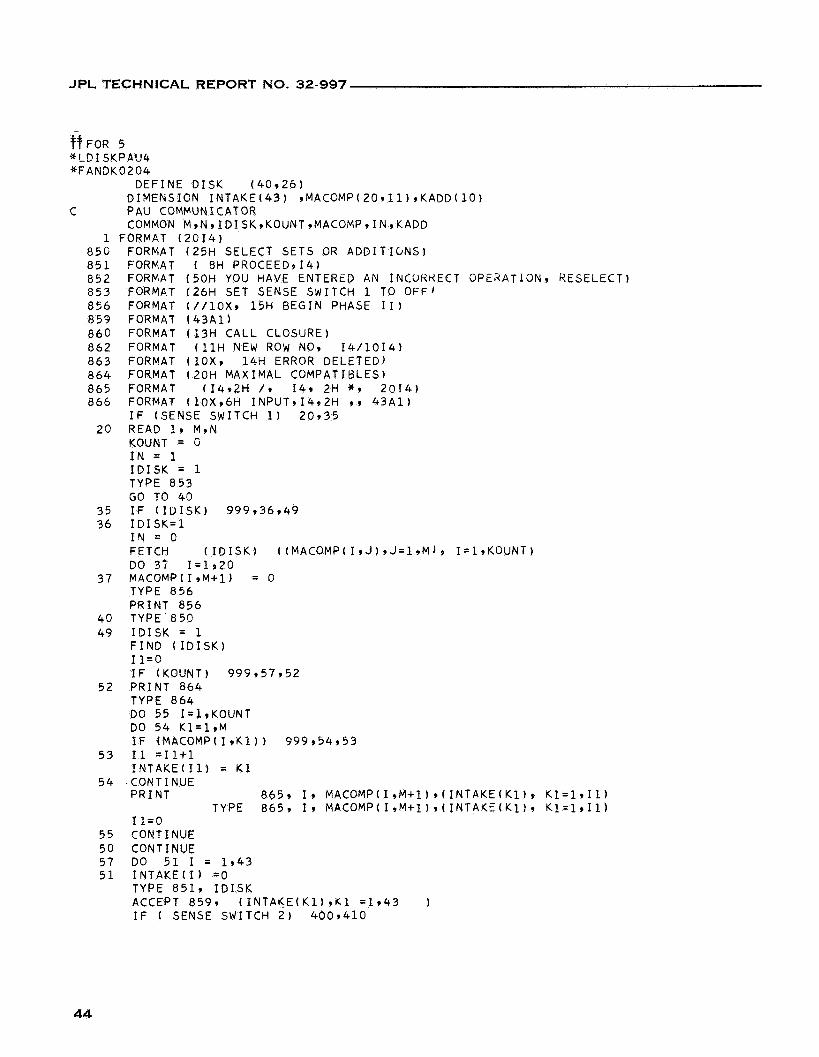
JPL TECHNICAL REPORT NO. 32-997
FOR 5 * L D I SYPAU4 *FAN3K0204
CEFINE D I S K ( 4 0 9 2 6 ) DIMENSION I N T A K E ( 4 3 ) 9MACOMP(20911) ,KADD( lO)
COMMON M9N9ID ISK,KOUNT9MACOMP, IN ,KADD
8 5 0 FORMAT ( 2 5 H SELECT SETS OR A D D I T I C N S ) 8 5 1 FORMAT ( 8H PROCEED9141 8 5 2 FORMAT ( 5 0 H YOU HAVE ENTERtD AN INCURKECT OPERATION, RESELECT) 8 5 3 FORMAT ( 2 6 H SET SENSE SWITCH 1 TO OFF' 856 FORMAT ( / / l o x , 15H BEGIN PHASE 1 1 ) 8 5 9 FORMAT ( 4 3 A 1 ) 8 6 0 FORMAT ( 1 3 H CALL CLOSURE) 8 6 2 FORMAT ( ? 1 H NEW ROW NO, 1 4 / 1 0 1 4 ) 8 6 3 FORMAT ( 1 0 x 9 1 4 H ERROR DELETED) 8 6 4 FORMAT ( 2 0 H M A X I M A L COMPATIBLES) 8 6 5 FORMAT ( 1 4 ~ 2 H / * 149 2H * 9 2 0 1 4 ) 8 6 6 FORMAT ( 1 0 X v 6 H INPUT91492H 9 ) 4 3 A 1 )
C PAU COMMUNICATOR
1 FORMAT ( 2 0 1 4 )
I F (SENSE SWITCH 1 ) 2 0 9 3 5
KOUNT = G I N = 1 I D I S K = 1 TYPE 8 5 3 GO TO 4 0
2 0 READ 1, M9N
3 5 I F ( I U I S K ) 9 9 9 , 3 6 9 4 9 3 6 I D I S K = l
I N = 0 FETCH ( I D I S K ) ( ( M A C O M P ( I , J I r J = l , M ) , I = l r K O U N T ) DO 37 1 = 1 9 2 0
TYPE 8 5 6 PRINT 8 5 6
4 0 TYPE 8 5 0 49 I D I S K = 1
F I N D ( I D I S K ) I 1 = O I F (KOUNT) 9 9 9 , 5 7 9 5 2
5 2 PRINT 8 6 4 TYPE 8 6 4 DO 5 5 I= l ,KOUNT DO 5 4 K l ' l r M IF (MACOMPI1 ,K l ) ) 9 9 9 9 5 4 9 5 3
I N T A K E ( I 1 ) = K 1
3 7 MACOMP(I,M+l) = 0
5 3 I 1 =11+1
5 4 .CONTINUE P R I N T 865, 1 9 MACOMP(I9M+l),(INTAKE(K1), K 1 = 1 9 1 1 )
TYPE 8 6 5 , I, MACOMP(I,M+l)*(INTAKE(Kl), K 1 = 1 9 1 1 ) I 1 = 0
5 5 CONTINUE 5 0 CONTINUE 5 7 DO 5 1 I = 1 9 4 3 5 1 I N T A K E ( 1 ) =O
TYPE 8519 I D I S K ACCEPT 8 5 9 9 ( I N T A K E ( K l I v K 1 ~ 1 9 4 3 I F ( SENSE SWITCH 2 ) 4 0 0 9 4 1 0
44
JPL TECHNICAL REPORT NO. 32-997
400
C 410
4 2 0
C 6 2 6 5
7 c 7 5
7 7
C 8 0 9 5
C 97 9 4
99 96
30c 3 2 5 3 4 0
C
C
100
9 9 9 9 9 8
TYPE 8 6 3 GO TO 5 0 REP.D MACOMP CONTINUE P R I N T 8 6 6 9 I D I S K , INTAKE I F ( I N T A K E ( 3 ) - 4100) 6 0 9 4 2 0 9 6 0 CONT I NUE GO TO 100 ADD/AND I F ( I N T A K E ( 1 ) - 4 1 0 0 ) 7 0 9 6 5 3 7 0 K A D D ( I D I S K ) = l GO TO 1 O G SELECT I F ( I N T A K E ( 1 ) - 6 Z G O ) 8 0 9 7 5 9 8 0 KADD( I D I S K 1 = 2 DO 77 I = 1 9 2 0 MACOMP(I,M+l) = 0 GO TO 100 REPLACE I F ( I N T A K E ( 1 ) - 5 9 0 0 ) 9 7 9 9 5 , 9 7 KADD( I D I S K 1 = 4 GO TO 100 GO I F ( I N T A K E ( 1 ) - 4 7 0 0 ) 99994999 CALL L I N K ( P A U 6 ) ENTER I F ( I N T A K E ( 1 ) - 4 5 0 0 ) 3 0 0 , 9 6 9 3 0 0 CALL L I N K ( P A U 5 ) HALT I F ( I N T A K E I 1 ) - 4 8 0 0 ) 3 4 0 9 3 2 5 , 3 4 0 STOP
GO T O 50 RECORD(ID1SK) ( I N T A K E ( I 1 9 1=1+40) GO TO 5 0 PRINT 998
END
TYPE 8 5 2
FORMAT ( 1 C H GOOF STOP)
45
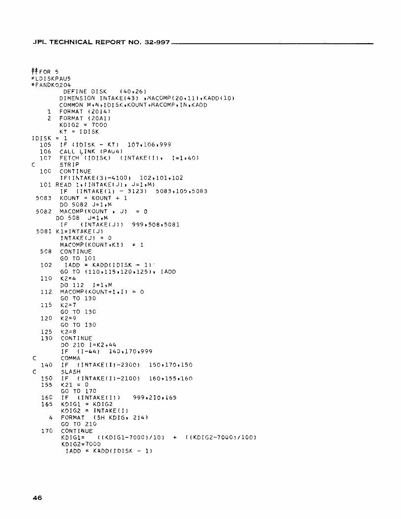
JPL TECHNICAL REPORT NO. 32-997
$+FOR 5 *LDI SYPAU5 *FANDK0204
DEFINE DISK (40,261 DIMENSION INTAKE(43) rMACOMP(20,11),KADD(lO) COMMON M,N,IDISK,KOUNT,MACOMP,IN,KADD
1 FORMAT (2014) 2 FORMAT (20A1)
KDIG2 = 7000 KT = IDISK
IDISK = 1 105 IF (IDISK - KT) 107,106,999 106 CALL &INK (PAU4) 1 C 7 FETCH (IDISK) (INTAKE(I1, I=1+40)
100 CONTINUE
101 READ l,(INTAKE(J), J=l,M)
C STRIP
IF(IhTAKE(3)-4100) 102~101,102
IF (INTAKE(1) - 3123) 5083,105,5083
DO 5082 J=l,M 5083 KOUNT = KOUNT + 1
5082 MACOMP(K0UNT 9 J) = 0 DO 508 J=l,M IF (INTAKE(J1) 999,508,5081
5081 Kl=INTAKE(J) INTAKEtJ) = 0 MPCOMP(KOUNT,Kl) = 1
GO TO 101
GO TO ( 1 1 0 ~ 1 1 5 ~ 1 2 0 ~ 1 2 5 ) ~ IADD
DO 112 I=l,M
GO TO 130
GO TO 130
GO TO 130
508 CONTINUE
102 IADD = KADD(ID1SK - 1) 110 K2=4
112 MACOMP(KOUNT+l,f) = 0
115 K2=7
120 K2=9
125 Y Z = 8 133 CONTINUE
DO 210 I=K2,44 IF (1-441
C COMMA
C SLASH 140 IF (INTAKE
150 IF (INTAKE 155 Y21 = 0
166 IF (INTAKE GO TO 170
140,1709999
1)-2300) 150,170,150
1)-2100) 160,155*16@
I ) 1 999,210,165 165 KDIG1 = KDIG2
KDIG2 = IN.TAKE(I) 4 FORMAT (5H KDIG, 214)
GO TO 210
KDIGl= ((KDIG1-7000)/10) + ((KDIG2-70DG)/100) KDIG2=70GO
170 CONTINUE
IADD = K4DD(IDISK - 1 )
46
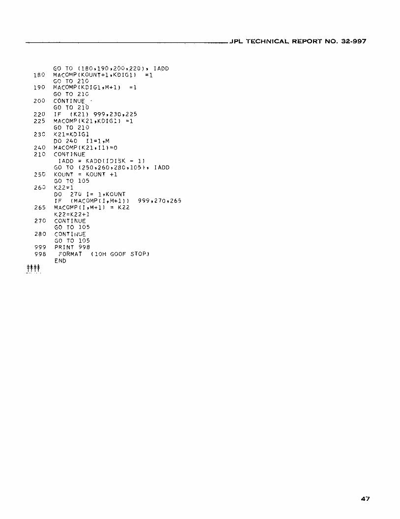
JPL TECHNlCAL REPORT NO. 32-997
180
190
200
220 225
233
240 213
25c
26G
265
270
280
999 998
GO TO (18C~190,200~220), IADD MACOMP(KOUNT+l,KDIGl) =1 GC: TO 210 MACOMP(KDIGl,M+l) =1 GO TO 21C CONTINUE GO TO 210 IF (K21) 999,2309225 MPCOMP(Y2lrKDIGl) =1 GO TO 210 Y21=KDIG1 DO 240 Il=lrM MACOMP(K21911)=0 C0N.T I-NUE
GO TO (2509260928C,105), IADD KOLJNT = KOUNT +1 GO TO 105 Y22=1 DO 270 I= 1,KOUNT IF (MACOMP(I,M+l)) 999,270,265 MACOMP(I,M+l) = K22 K22=K22+1 CONTINUE GO TO 105 CONT I f4UE GO TO 105 PRINT 998
END
IADD = KADD(ID1SK - 1 )
FORMAT (10H GOOF STOP)
47
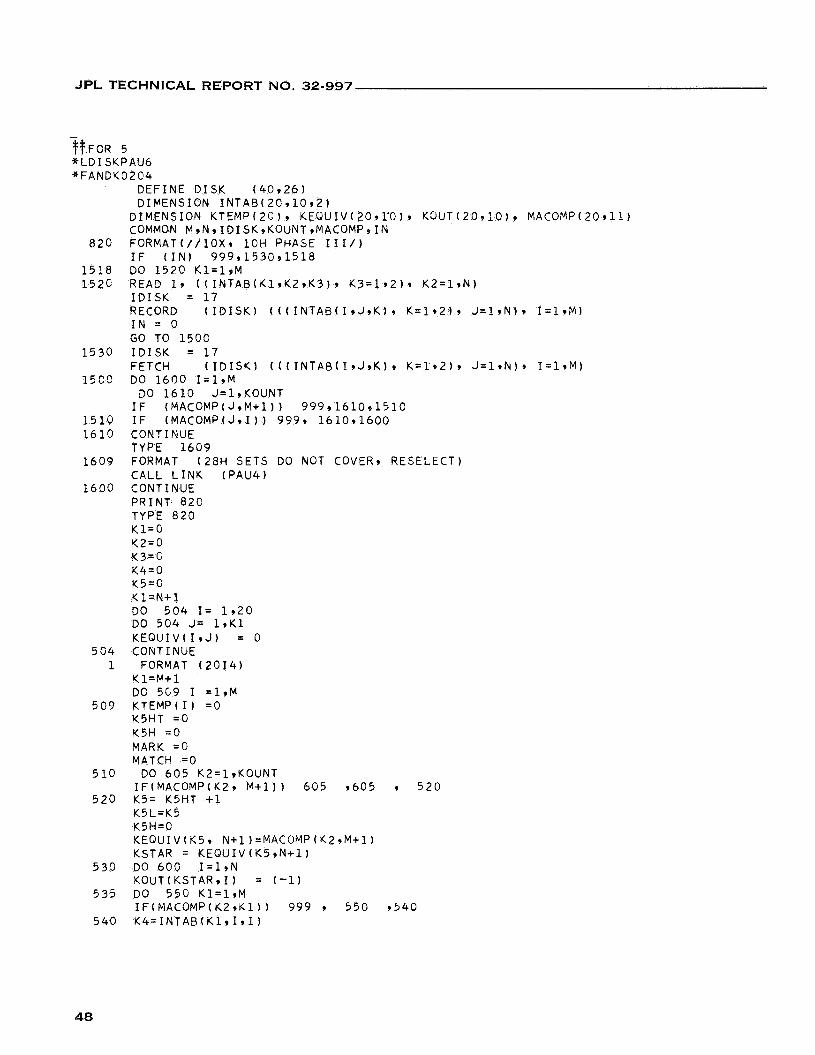
JPL TECHNICAL REPORT NO. 32-997
-
~ ~ F O R 5 *LDISKPAU6 *FANDY0204
DEFINE DISK (40926) DIPENSION INTAB(2C910,21
DIMENSION KTEMP(2C)q KEQUIV(20,rO), K3UT(20,10), MACOMP(20911) COMMQN M,N,IDISK,KOUNT,MACOMP,IN
820 FORMATI//lOX, 10H PHASE I I I / ) IF (IN) 999,153091518
1518 DO 1520 K1=1,M 152c READ 1, ((INTAB(KlrK2,K3)9 K3=192), K2=1,N)
IDISK = 17 RECORD (IDISK) (((INTAB(I,J,K), K=1,2)9 J=lrN), I=lrM) IN = 0 GO TO 1500
1530 IDISK = 17 FETCH (IDISK) (((INTAB(I,J,K), K=192)r J=lrN), I=lrM)
15C0 DO 1600 I=l,M DO 1610 J=l,KOUNT IF (MACOMP(J,M+l)) 999r161091510
1510 IF (MACOMP(J,I)) 9999 1610,1600 1610 CONTINUE
TYPE 16G9 1609 FORMAT (28H SETS DO NOT COVER, RESELECT)
CALL LINK (PAU4) 160C CONTINUE
PRINT 820 TYPE 820 K l = G Y2=0 K3=G Y4=0 K5=0 Kl=N+1 DO 504 I = 1920 DO 504 J= 1,Kl KEQUIV(1,J) = 0
5G4 CONTINUE 1 FORMAT (2014)
Yl=M+l
509 KTEMP(I1 = O K5HT = O K5H = O MARK = O MATCH =O
DO 5C9 I =1,M
510 DO 605 K2=19KOUNT IF(MACOMP(K2, M + 1 ) ) 605 ,605 9 520
520 K5= K5HT +1 K5L=K5 K5H=C KEQUIV(K5, N+l)=MACOMP(K2,M+l) KSTAR = KEQUIV(K5,N+l)
KOUT(KSTAR91) = (-1)
IF(MACOMP(K2,Kl)) 999 9 550 ,540
530 DO 600 I=l,N
535 DO 556 Kl=l,M
5 4 0 K4=INTAB(Kl,I,l)
48
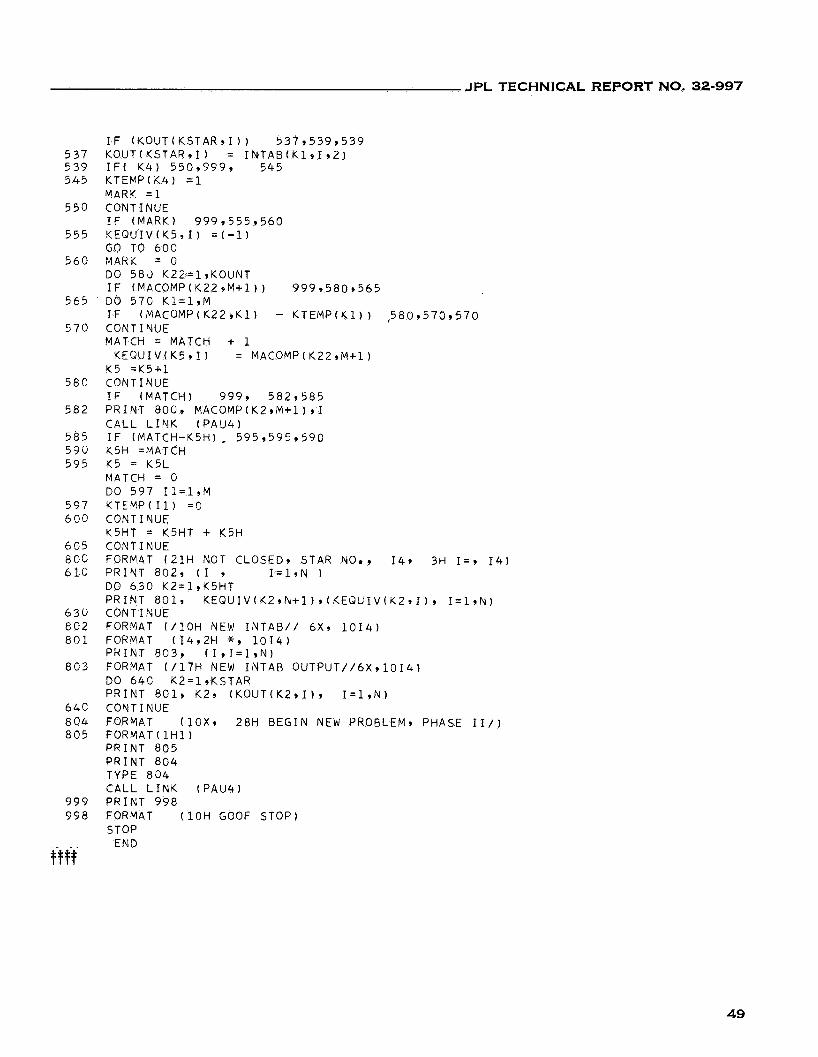
JPL TECHNICAL REPORT NO. 32-997
5 3 7 5 3 9 5 4 5
5 5 0
5 5 5
5 6 0
5 6 5
5 7 0
5 8 0
5 8 2
5 8 5 5 9 0 5 9 5
5 9 7 6 9 0
6 9 5 8 0 3 6l .C
6 3 i j E 0 2 8 0 1
8 0 3
64C 8 0 4 8 0 5
9 9 9 9 9 8
fw
I F ( K O U T ( K S T A R 9 1 ) ) 5 3 7 9 5 3 9 , 5 3 9 KOUT(KSTAR91) = I N T A S ( K 1 9 1 , Z ) I F ( K 4 ) 550,999, 5 4 5 KTEMP(K4) =1 MAR!? =1 CONTINUE I F ( M A R I O 999 ,555 ,560 K E Q U I V ( Y 5 9 1 ) =(--l) GO TO 600 M A R K = 0 DO 5 8 3 K22=1,KOUNT I F (MACOMP(K229M+1)) 9 9 9 3 5 8 0 9 5 6 5 DO 5 7 0 K1=1,M I F (MACOMP(K22,Kl ) - K T E M P ( K 1 ) ) .580,570,570 CONTI NUE MATCH = MATCH + 1
Y5 =K5+1 CONT I NUE I F (MATCH) 9 9 9 , 582 ,585 PRINT 8 0 6 3 MACOMP(KZ,M+l) , I C A L L L I N K ( P A U 4 ) I F (MATCH-K5H), 5 9 5 9 5 9 5 , 5 9 0 K5H =MATCH K5 = K5L MATCH = 0
K T E M P ( I 1 ) = O CONTINUE K5HT = K5HT + K5H CONTINUE FORMAT ( 2 1 H NOT CLOSED, STAR NO., 14, 3H I = , 1 4 ) PRINT 802 , (I 9 I = l , N 1 DO 6 3 0 K2=1,K5HT PRINT 801, K E Q U I V ( K 2 , N + l ) , ( K E Q U I V O , I = 1 9 N ) CON T I NUE FORMAT ( / 1 0 H NEW I N T A B / / 6 x 9 1 0 1 4 ) FORMAT ( 1 4 r 2 H *, 1 0 1 4 ) PRINT 8 0 3 , ( I v I = l , N ) FORMAT ( / 1 7 H NEW INTAB O U T P U T / / 6 X , l O I 4 ) DO 64C K2=19KSTAR PRINT 801, K29 ( K O U T ( K 2 , I ) v I = l , N ) CONTINUE FORMAT ( 1 0 x 9 28H BEGIN NEW PROELEM, PHASE II/) F O R M A T ( l H 1 ) PRINT 8 0 5 PRINT 8 0 4 TYPE 8 0 4 CALL L I N K (PAU41 PRINT 9 9 8 FORMAT ( 1 0 H GOOF STOP) STOP
EN3
K E Q U I V ( K 5 , I ) = MACOMP(K22,M+l)
DO 5 9 7 I 1 = 1 , M
49
JPL TECHNICAL REPORT NO. 32-997
REFERENCES
1. Maley, G., and Earle, J., The Logic Design of Transistor Digital Computers, pp. 271 - 272, Prentice Hall, 1964.
2. Caldwell, S. H., Switching Circuits and Logic Design, pp. 470-479, John Wiley & Sons, Inc., 1958.
3. Paull, M. C., and Unger, S. H., "Minimizing the Number of States in Incompletely Specified Sequential Switching Functions," IRE Transactions on Electronic Com- puters, pp. 346-367, September 1959.
4. Grasseli, A., and Luccio, F., "A Method for Minimizing the Number of Internal States in Incompletely Specified Sequential Networks," I€€€ Transactions on E/ec- tronic Computers, pp. 350-359, June 1965.
50