Embed Size (px)
Citation preview

DESIGN MANUAL: SEWAGE DISPOSAL SYSTEMS IN PRINCE GEORGE’S COUNTY
Revised: March 7, 2018 1
Environmental Engineering/Policy Program Largo Government Center 9201 Basil Court, Suite 318
Largo, Maryland 20774
Prince George’s County Department of Permitting, Inspections and Enforcement Health Review Section 9400 Peppercorn Place, 2nd Floor Largo, Maryland 20774 301.883.7621
DESIGN MANUAL: SEWAGE DISPOSAL SYSTEMS IN PRINCE GEORGE’S COUNTY
Revised: March 7, 2018 2
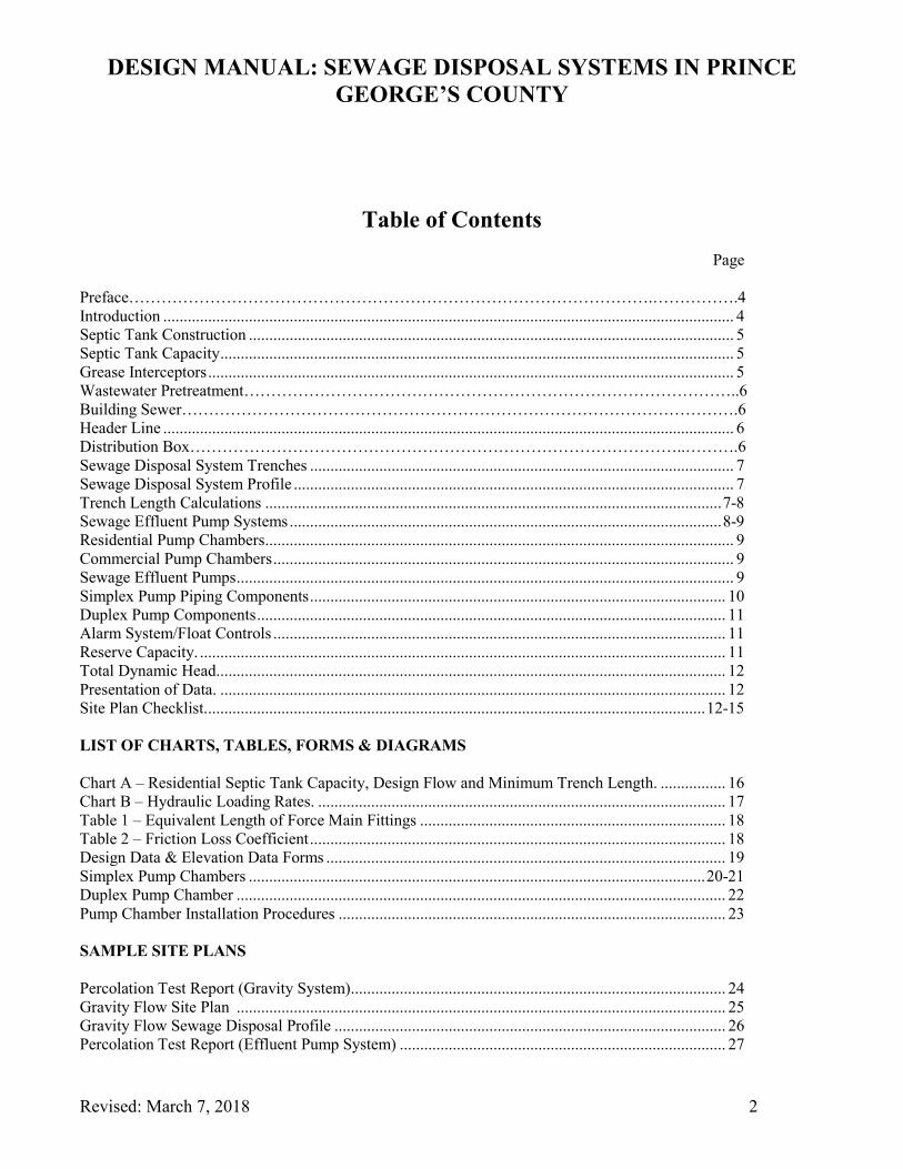
Table of Contents Page Preface…………………………………………………………………………………….…………….4 Introduction ............................................................................................................................................ 4 Septic Tank Construction ....................................................................................................................... 5 Septic Tank Capacity .............................................................................................................................. 5 Grease Interceptors ................................................................................................................................. 5 Wastewater Pretreatment………………………………………………………………………………..6 Building Sewer………………………………………………………………………………………….6 Header Line ............................................................................................................................................ 6 Distribution Box………………………………………………………………………………..……….6 Sewage Disposal System Trenches ........................................................................................................ 7 Sewage Disposal System Profile ............................................................................................................ 7 Trench Length Calculations ................................................................................................................ 7-8 Sewage Effluent Pump Systems .......................................................................................................... 8-9 Residential Pump Chambers ................................................................................................................... 9 Commercial Pump Chambers ................................................................................................................. 9 Sewage Effluent Pumps .......................................................................................................................... 9 Simplex Pump Piping Components ...................................................................................................... 10 Duplex Pump Components ................................................................................................................... 11 Alarm System/Float Controls ............................................................................................................... 11 Reserve Capacity. ................................................................................................................................. 11 Total Dynamic Head............................................................................................................................. 12 Presentation of Data. ............................................................................................................................ 12 Site Plan Checklist. .......................................................................................................................... 12-15 LIST OF CHARTS, TABLES, FORMS & DIAGRAMS Chart A – Residential Septic Tank Capacity, Design Flow and Minimum Trench Length. ................ 16 Chart B – Hydraulic Loading Rates. .................................................................................................... 17 Table 1 – Equivalent Length of Force Main Fittings ........................................................................... 18 Table 2 – Friction Loss Coefficient ...................................................................................................... 18 Design Data & Elevation Data Forms .................................................................................................. 19 Simplex Pump Chambers ................................................................................................................ 20-21 Duplex Pump Chamber ........................................................................................................................ 22 Pump Chamber Installation Procedures ............................................................................................... 23 SAMPLE SITE PLANS Percolation Test Report (Gravity System)............................................................................................ 24 Gravity Flow Site Plan ........................................................................................................................ 25 Gravity Flow Sewage Disposal Profile ................................................................................................ 26 Percolation Test Report (Effluent Pump System) ................................................................................ 27

DESIGN MANUAL: SEWAGE DISPOSAL SYSTEMS IN PRINCE GEORGE’S COUNTY
Revised: March 7, 2018 3
Effluent Pump System Site Plan ........................................................................................................... 28 Effluent Pump Sewage Disposal Profile .............................................................................................. 29 Effluent Pump System Design and Elevation Data for Separate Pump Chamber Tank ....................... 30 APPLICATIONS Sewage Disposal Permit Application…………………………………………………………………31

DESIGN MANUAL: SEWAGE DISPOSAL SYSTEMS IN PRINCE GEORGE’S COUNTY
Revised: March 7, 2018 4
Preface
Prince Georges County utilizes septic tanks and BAT (Best Available Technology) units for onsite sewage disposal systems for residential and commercial properties. BAT units are required for new construction in the Chesapeake Bay and Atlantic Coastal Bay Critical Area (within 1000’ of Tidal Water). However, a BAT system may be required outside the Critical Area in order to protect public health or the waters of the State. Commercial establishments having flows of 5,000 gallons per day or greater shall be reviewed and approved concurrently by the Maryland Department of the Environment (MDE) and this office.
This current manual supersedes all earlier versions
Introduction
This manual provides instructions on the design of on-site residential and commercial sewage disposal systems utilizing septic tanks only; and encompasses conventional gravity flow and effluent pump systems for new/existing residential and commercial establishments that are outside the Chesapeake Bay and Atlantic Coastal Bay Critical Area (within 1000’ of Tidal Water). Sand mound, low-pressure distribution systems, shared SDS, and non-conventional on-site SDS technologies are not addressed in this manual. For sewage disposal systems using BAT (Best Available Technology) units, please use the design manual entitled Sewage Disposal Systems in Prince George’s County - BAT Units. For the purposes of this manual it is assumed that the properties to be served have satisfactory percolation tests conducted on or after 1985 and have an adequate sewage disposal area (SDA). Percolation tests conducted prior to this date employed a different methodology and must be reviewed on a case by case basis to determine whether additional testing is necessary. The SDA shall be exclusive of buildings, easements, right-of-ways, pools, storm water infiltration devices or other structures that may damage the initial sewage disposal system (SDS) or limit the use of the remaining SDA. No grading shall occur within the SDA except for clearing activities necessary to install the initial SDS.
The information and requirements described in this manual complies with the Prince George’s County Code, Subtitle 22, the Code of Maryland Regulations 26.04.02, and the Prince George’s County policy guidelines. High strength wastewater must be pretreated and reduced to typical domestic septic tank effluent levels. For systems that have high strength wastewater, it is recommended that you contact this office or MDE to discuss specific design requirements. For these and all other questions you may have regarding the design of Sewage Disposal Systems in Prince George’s County, please contact the Division of Environmental Health’s Environmental Protection/Policy Program at 301/883-7681 or the Health Review Section of the Department of Permitting, Inspections and Enforcement (DPIE) at 301/883-7621.

DESIGN MANUAL: SEWAGE DISPOSAL SYSTEMS IN PRINCE GEORGE’S COUNTY
Revised: March 7, 2018 5
Septic Tank Construction
Septic tanks are typically pre-cast concrete, and shall have two compartments with top seam construction. Inlet and outlet pipes shall be installed with four-inch sanitary tees constructed of schedule 40 PVC or its equivalent. Tanks that must be installed partially in the groundwater or subject to seasonally high groundwater shall be certified “water tight” and be tarred by the manufacturer. Tanks placed in the groundwater that have minimal soil cover shall be strapped and anchored prior to backfilling. Tanks buried three or more feet in the ground or subject to vehicular traffic shall be traffic bearing in construction. All tanks buried deeper than one foot shall have 24-inch diameter access risers to within 6 inches above grade. Tanks constructed of fiberglass or other composite materials must be approved for use by the MDE.
Septic Tank Capacity
Residential Systems The tank size is determined by the square footage of the residence, which includes all finished basement areas and one third of unfinished basements having rough-in plumbing. Do not include garage space or unfinished basements without sewer lines. Once the square footage of the living area is calculated, refer to Chart A (page 16), to determine the required tank size. Commercial Systems The size and type of septic tank used to provide primary sewage treatment for a commercial operation is dependent upon both the volume and strength of the wastewater generated by the facility. When hydraulic loading is the primary concern, the tank volume will be twice the expected daily sewage flow. The daily sewage flow can be calculated using the recommended wastewater flow figures established by the Maryland Department of the Environment (MDE) or from actual flow figures of similar establishments. Commercial operations having highly variable daily sewage flows (i.e. a church), should use the peak daily flow, not an average weekly or monthly flow figure when determining tank capacity. Commercial systems utilizing specialized tanks designed to pre-treat high strength wastewater will be sized to conform to the manufacturer’s recommendations. The minimum septic tank capacity shall be 1,000 gallons.
Grease Interceptors
All commercial operations producing fats, oils or grease shall discharge to an outside grease interceptor. This high strength wastewater shall be isolated from the building’s gray and black water and be plumbed directly into the grease interceptor before entering the septic tank or pretreatment tank. The grease interceptor shall conform to all Washington Suburban Sanitary Commission (WSSC) design and construction standards.

DESIGN MANUAL: SEWAGE DISPOSAL SYSTEMS IN PRINCE GEORGE’S COUNTY
Revised: March 7, 2018 6
Wastewater Pretreatment
Wastewater must be pretreated whenever primary treatment tanks (septic tanks and grease interceptors) cannot lower the levels of fats, oils, grease, nitrates or other constituents below concentrations found in domestic septic tank effluent or to levels below that considered detrimental to the environment. As an example, wastewater from restaurants, which is typically high in fats, oils and grease, should not exceed 25 parts per million (ppm) for fats, oils and grease, 75 ppm for total suspended solids and 150 ppm for the five-day biochemical oxygen demand (BOD-5). Meeting these performance standards shall require the installation of specialized pretreatment tanks, such as aerobic tanks, that are designed to accommodate specific flows and sewage strengths. Nitrate reduction shall be required for systems impacting the public health or the tributaries of the Chesapeake Bay.
Building Sewer
The building sewer shall be installed in accordance with all applicable WSSC regulations. A minimum 2% slope is required for the building sewer.
Header Line
The header line, which allows gravity flow from the tank to the distribution box, shall be four inches in diameter, have a minimum 1% slope and be constructed of Schedule 40 PVC or equivalent. Header lines installed 24 inches or deeper beneath driveways or right–of–ways that are subject to vehicular traffic, shall be laid in a two-inch bed of ¾ inch gravel or sleeved in cast iron pipe or Schedule 80 PVC. Header lines installed less than 24 inches below grade shall be sleeved in cast iron pipe or Schedule 80 PVC.
Distribution Box
The majority of gravity-based septic systems utilize a six-hole distribution box. Gravity systems having six or more trenches and all pump systems must use ten-hole distribution boxes. The distribution box lid shall be constructed with an integral PVC fitting that will allow for the installation of a three or four-inch diameter inspection pipe.
Sewage Disposal System Trenches
Trenches shall be drawn on contour and be a maximum of 100 feet in length. When showing multiple trenches, the trenches shall be equal in length. The trenches should be installed through or adjacent to one or more percolation tests. It is always preferable to design the initial system in the uppermost

DESIGN MANUAL: SEWAGE DISPOSAL SYSTEMS IN PRINCE GEORGE’S COUNTY
Revised: March 7, 2018 7
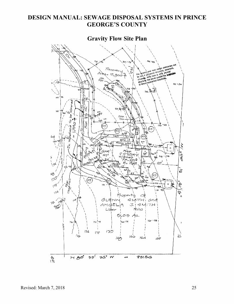
elevations of the SDA as it will allow future trenches to be installed via gravity from the distribution box. Refer to pages 25 and 28 that present site plans of both a gravity flow system and a pump system. Deep trenches (greater than or equal to five feet deep) that are installed parallel shall be spaced at least twice the gravel depth apart, measured sidewall to sidewall. The distance between trenches may not be less than 10 feet nor more than 18 feet. Shallow trenches (two feet to four feet eleven inches deep) shall be constructed three feet wide and spaced at least nine feet apart. Observation pipes, which extend from the bottom of the trench to finished grade, shall be installed at the end of every trench. Commercial SDS’s require dual drain fields that utilize either a diversion valve or gate valves to divert effluent from one field to the other field. Valves are usually switched on a yearly basis.
Sewage Disposal System Profile
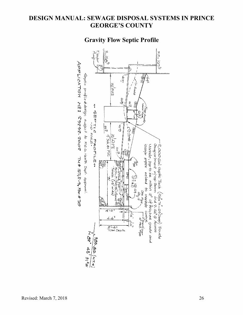
A profile of the SDS must be included on the site plan. The profile shall accurately depict all components of the SDS, their associated elevations and slopes. Profiles for both gravity and effluent pump systems are shown on pages 26 and 29. When it is necessary to install a pump chamber greater than 24 inches below grade, the force main should be shown exiting the side of the riser of the pump chamber. This will allow the pump motor to be easily removed without entering the tank. Refer to pages 21-22.
Trench Length Calculations
Calculate the total length of trench for both residential and commercial systems by determining the sewage design flow (peak flow), the soil loading rate and the amount of absorptive soil in the percolation tests holes located in closest proximity to the proposed drain field trenches.
• Sewage Design Flow (peak flow) The peak flows for residential Sewage Disposal Systems have been incorporated in the minimum design flows shown in Chart A (page16). For commercial systems, peak flows are calculated by doubling the projected average daily flow obtained from the MDE wastewater flow figures or from the actual flow figures of similar operations. When both methods are utilized, the method that produces the more conservative number will be used. The minimum commercial design flow is 400 gpd. It is recommended that you contact the Health Review Section of DPIE and/or the Environmental Health’s Environmental Protection/Policy Program to determine the design flow for any commercial project.
• Soil Loading Rates The soil loading rates for shallow and deep percolation tests are found in Chart B. When one is confronted with varying percolation test rates within the SDS area, normally the average of those rates is used in the design of the system. To design systems based on percolation tests having

DESIGN MANUAL: SEWAGE DISPOSAL SYSTEMS IN PRINCE GEORGE’S COUNTY
Revised: March 7, 2018 8
rates greater than 30 minutes per inch, please contact the Environmental Protection/Policy Program for additional instructions.
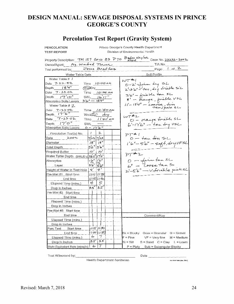
• Absorptive Soil Data The amount of absorptive soil identified in each percolation test is stated in the percolation test report, under absorptive soils (see page 24). For deep SDS’s based on percolation tests five feet and deeper, only permeable soils found from 18 inches below grade to the bottom of the test hole shall be considered absorptive for the purpose of calculating trench length. For shallow SDS’s, less than five feet in depth, only the bottom of the trench is considered in the treatment of wastewater. Therefore, when designing shallow SDS’s, use the width of the trench, typically three feet, as the available absorptive soil factor in calculating total trench length.
Residential Systems The minimum size sewage drainfield systems required for residential buildings are shown in Chart A on page 16 and Loading Rates are found on Chart B page 17. Use the following equation to determine if the total trench length shall exceed the minimum requirements:
Trench Length = _______ Daily Sewage Flow (gal/day) _________ Loading Rate (gal/sq. ft./day) x Absorptive Soil (ft.)
Commercial Systems All commercial systems shall utilize a diversion valve system with alternating drainfields in both the initial system and the replacement system. To determine the total amount of trench required for the initial system, use the following equation:
Total Trench Length = 2 x Daily Sewage Flow (gal/day)_ of the Initial System Loading Rate (gal/sq.ft/day) x Absorptive Soil (ft)
The above total length must be equally divided to produce two smaller alternating systems (trench length no greater than 100 feet) connected by a four-inch diversion valve or two gate valves. These two smaller alternating systems constitute the initial system. The minimum size commercial system shall consist of two 70-foot trenches. Repeat the above calculations to determine the total trench length with two smaller alternating systems for the replacement system.
Sewage Effluent Pump Systems
New subdivisions have trended toward lots having reduced acreage and very substantial homes. These changes have diminished opportunities to install gravity flow SDS’s and increased the need to install sewage effluent pump systems. Current sewage effluent pumps and alarm systems have proven to be both cost effective and extremely reliable. However, these technological improvements have not
DESIGN MANUAL: SEWAGE DISPOSAL SYSTEMS IN PRINCE GEORGE’S COUNTY
Revised: March 7, 2018 9
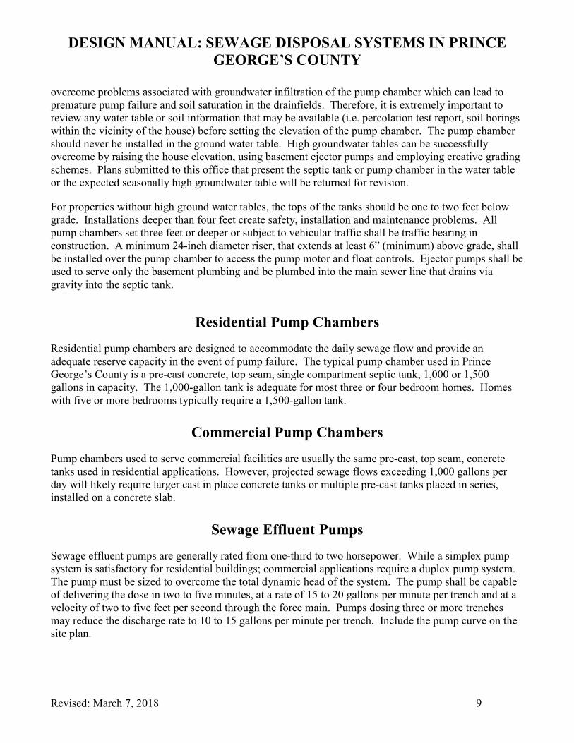
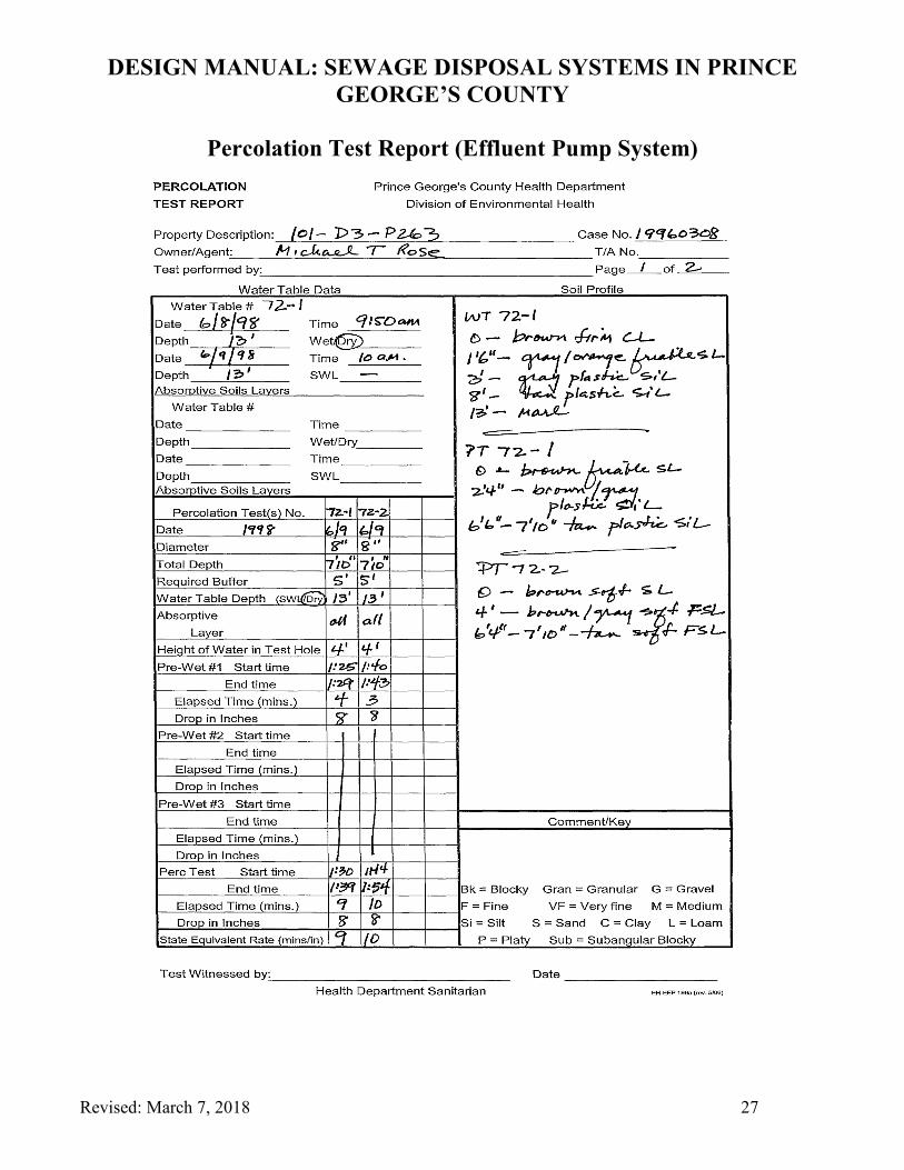
overcome problems associated with groundwater infiltration of the pump chamber which can lead to premature pump failure and soil saturation in the drainfields. Therefore, it is extremely important to review any water table or soil information that may be available (i.e. percolation test report, soil borings within the vicinity of the house) before setting the elevation of the pump chamber. The pump chamber should never be installed in the ground water table. High groundwater tables can be successfully overcome by raising the house elevation, using basement ejector pumps and employing creative grading schemes. Plans submitted to this office that present the septic tank or pump chamber in the water table or the expected seasonally high groundwater table will be returned for revision.
For properties without high ground water tables, the tops of the tanks should be one to two feet below grade. Installations deeper than four feet create safety, installation and maintenance problems. All pump chambers set three feet or deeper or subject to vehicular traffic shall be traffic bearing in construction. A minimum 24-inch diameter riser, that extends at least 6” (minimum) above grade, shall be installed over the pump chamber to access the pump motor and float controls. Ejector pumps shall be used to serve only the basement plumbing and be plumbed into the main sewer line that drains via gravity into the septic tank.
Residential Pump Chambers
Residential pump chambers are designed to accommodate the daily sewage flow and provide an adequate reserve capacity in the event of pump failure. The typical pump chamber used in Prince George’s County is a pre-cast concrete, top seam, single compartment septic tank, 1,000 or 1,500 gallons in capacity. The 1,000-gallon tank is adequate for most three or four bedroom homes. Homes with five or more bedrooms typically require a 1,500-gallon tank.
Commercial Pump Chambers
Pump chambers used to serve commercial facilities are usually the same pre-cast, top seam, concrete tanks used in residential applications. However, projected sewage flows exceeding 1,000 gallons per day will likely require larger cast in place concrete tanks or multiple pre-cast tanks placed in series, installed on a concrete slab.
Sewage Effluent Pumps
Sewage effluent pumps are generally rated from one-third to two horsepower. While a simplex pump system is satisfactory for residential buildings; commercial applications require a duplex pump system. The pump must be sized to overcome the total dynamic head of the system. The pump shall be capable of delivering the dose in two to five minutes, at a rate of 15 to 20 gallons per minute per trench and at a velocity of two to five feet per second through the force main. Pumps dosing three or more trenches may reduce the discharge rate to 10 to 15 gallons per minute per trench. Include the pump curve on the site plan.

DESIGN MANUAL: SEWAGE DISPOSAL SYSTEMS IN PRINCE GEORGE’S COUNTY
Revised: March 7, 2018 10
Simplex Pump Piping Components
Simplex pump systems are approved for residential applications and typically consist of the following components:
• A sewage effluent pump placed on a six-inch concrete cinderblock.
• Approximately six feet of two-inch diameter Schedule 40 PVC inside the tank, interlocked with a swing check valve, compression coupling and 90-degree elbow.
• A two-inch Diameter, Schedule 40 PVC force main, which extends from the pump chamber to
the distribution box. Large volume, commercial applications may require a three-inch diameter force main. The force main shall exit the outlet hole of the tank or through the riser when the tank is buried more than 24-inches below grade. Refer to the pump chamber diagrams on pages 20-21.
• It is recommended that the first 3’-5’ of force main is sleeved (with a larger diameter of pipe –Schedule 40) exiting out of the pump chamber to prevent stress damage of the force main.

DESIGN MANUAL: SEWAGE DISPOSAL SYSTEMS IN PRINCE GEORGE’S COUNTY
Revised: March 7, 2018 11
Duplex Pump Systems • All commercial facilities are required to utilize a duplex pump system. Duplex pump systems
consist of two independent pumps, each having a swing check valve, compression coupling and a 90-degree bend installed prior to a common tee fitting. Refer to the pump chamber diagram on page 22.
Alarm System/Float Controls
• Residential systems shall use a simplex controller with an alarm. Commercial systems employ a duplex controller with an alternator and an alarm. Both residential and commercial systems typically use a three-float, mercury control switch operation. A combination on/off float may be used if it can be adjusted to provide the proper dose. The floats shall be attached to a secured float tree or mounting bracket, independent of the force main that can be easily removed for adjustments and maintenance. A rain-tight, tamperproof junction box, used to connect the pump motor and float switches to the alarm box, shall be located outside the pump chamber. The alarm float and pump motor(s) shall be placed on separate electrical circuits.
Float Settings
• Off Float - Set the Off-Float elevation at the top of the motor housing. Depending on the manufacturer, the Off Float will be set at least 19 inches above the inside bottom of the tank. All motors shall be placed on six-inch concrete blocks.
• On Float – Set the On Float at three inches above the Off Float, or at an elevation equal to the volume of the entire four-inch perforated pipe (drawdown number from Design Data Form on page 19) in the drainfields, whichever is greater. Do not include the volume of the force main as the swing check valve restricts any drainage of the force main back into the tank.
• Alarm Float – Set the Alarm Float six inches above the On Float but below the invert of the inlet pipe entering the pump chamber.
Reserve Capacity
The reserve capacity of the pump tank is the volume between the Alarm Float and the invert of the inlet pipe. In residential simplex pump systems, the minimum reserve volume shall be 150 gallons per bedroom. For commercial systems, the reserve capacity must be equal to at least the projected one-day sewage flow.

DESIGN MANUAL: SEWAGE DISPOSAL SYSTEMS IN PRINCE GEORGE’S COUNTY
Revised: March 7, 2018 12
Total Dynamic Head (TDH)
To select the appropriate sewage effluent pump, calculate the TDH. The TDH is the sum of the friction and static head losses. Velocity head for residential and small commercial systems will be fractional and can be discounted when calculating TDH.
• Static Head Loss – The difference between the highest elevation of the force main, typically the invert of the distribution box, and the Off-Float elevation.
• Friction Loss – Calculate the equivalent length of all the two-inch force main pipe fittings, using Table 1 on page 18. Add this value to the length of the force main and the six feet of pipe inside the tank. Multiply the total length of pipe by the friction loss coefficient that correlates to the discharge rate in gallons per minute and divide by 100. Refer to Table 2, on page 18. The discharge rate shall be maintained between 15 to 20 gallons per minute per trench. When dosing more than three trenches, the discharge rate may be reduced to 10 to 15 gallons per minute per trench.
• Total Dynamic Head – Add the static and friction head loss. Select an effluent pump that is capable of providing the required discharge rate (gal/min) against the TDH.
Presentation of Data
The pump system elevation and design data shall be included on the site plan. The information can be tabulated and presented as shown on page 30.
Site Plan Checklist
The following checklist is a summary of the State and County requirements for properties to be developed on wells and/or SDS’s. Compliance with these Health Department requirements shall ensure a timely building permit approval process. Refer to the sample site plans, sewage disposal profiles and pump chamber data included in this manual. Be advised that as of June 2011, all SDS’s located within the Chesapeake Bay Critical Area require a variance from the Prince George’s Planning Board prior to the installation of the system.
General Site Plan Information 1. Provide the owner’s name, address and telephone number. 2. Indicate the property location: street, address, tax map, grid, and parcel or lot number. 3. Use a scale of between 1:10 to 1:50. 4. Provide one or two-foot contour elevations. Show the original and final grades. 5. Provide a footprint of the house, deck, driveway, and all other permanent structures that may
impact the well and/or SDA. 6. Show the tree conservation area.
DESIGN MANUAL: SEWAGE DISPOSAL SYSTEMS IN PRINCE GEORGE’S COUNTY
Revised: March 7, 2018 13
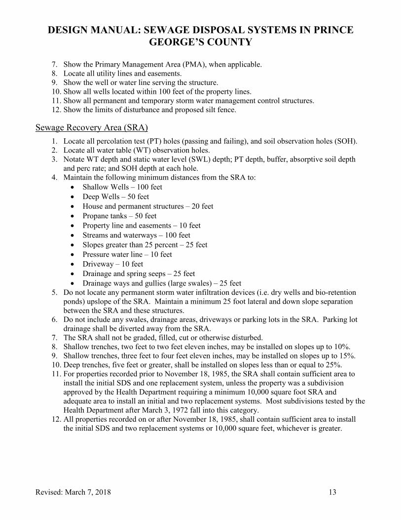
7. Show the Primary Management Area (PMA), when applicable. 8. Locate all utility lines and easements. 9. Show the well or water line serving the structure. 10. Show all wells located within 100 feet of the property lines. 11. Show all permanent and temporary storm water management control structures. 12. Show the limits of disturbance and proposed silt fence.
Sewage Recovery Area (SRA) 1. Locate all percolation test (PT) holes (passing and failing), and soil observation holes (SOH). 2. Locate all water table (WT) observation holes. 3. Notate WT depth and static water level (SWL) depth; PT depth, buffer, absorptive soil depth
and perc rate; and SOH depth at each hole. 4. Maintain the following minimum distances from the SRA to:
• Shallow Wells – 100 feet • Deep Wells – 50 feet • House and permanent structures – 20 feet • Propane tanks – 50 feet • Property line and easements – 10 feet • Streams and waterways – 100 feet • Slopes greater than 25 percent – 25 feet • Pressure water line – 10 feet • Driveway – 10 feet • Drainage and spring seeps – 25 feet • Drainage ways and gullies (large swales) – 25 feet
5. Do not locate any permanent storm water infiltration devices (i.e. dry wells and bio-retention ponds) upslope of the SRA. Maintain a minimum 25 foot lateral and down slope separation between the SRA and these structures.
6. Do not include any swales, drainage areas, driveways or parking lots in the SRA. Parking lot drainage shall be diverted away from the SRA.
7. The SRA shall not be graded, filled, cut or otherwise disturbed. 8. Shallow trenches, two feet to two feet eleven inches, may be installed on slopes up to 10%. 9. Shallow trenches, three feet to four feet eleven inches, may be installed on slopes up to 15%. 10. Deep trenches, five feet or greater, shall be installed on slopes less than or equal to 25%. 11. For properties recorded prior to November 18, 1985, the SRA shall contain sufficient area to
install the initial SDS and one replacement system, unless the property was a subdivision approved by the Health Department requiring a minimum 10,000 square foot SRA and adequate area to install an initial and two replacement systems. Most subdivisions tested by the Health Department after March 3, 1972 fall into this category.
12. All properties recorded on or after November 18, 1985, shall contain sufficient area to install the initial SDS and two replacement systems or 10,000 square feet, whichever is greater.
DESIGN MANUAL: SEWAGE DISPOSAL SYSTEMS IN PRINCE GEORGE’S COUNTY
Revised: March 7, 2018 14
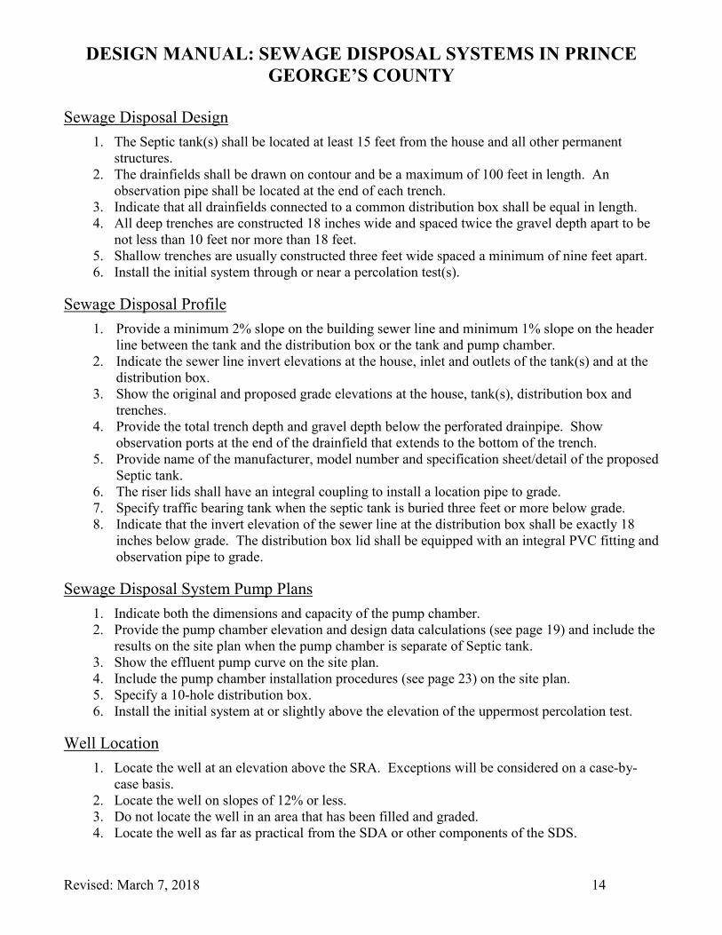
Sewage Disposal Design 1. The Septic tank(s) shall be located at least 15 feet from the house and all other permanent
structures. 2. The drainfields shall be drawn on contour and be a maximum of 100 feet in length. An
observation pipe shall be located at the end of each trench. 3. Indicate that all drainfields connected to a common distribution box shall be equal in length. 4. All deep trenches are constructed 18 inches wide and spaced twice the gravel depth apart to be
not less than 10 feet nor more than 18 feet. 5. Shallow trenches are usually constructed three feet wide spaced a minimum of nine feet apart. 6. Install the initial system through or near a percolation test(s).
Sewage Disposal Profile 1. Provide a minimum 2% slope on the building sewer line and minimum 1% slope on the header
line between the tank and the distribution box or the tank and pump chamber. 2. Indicate the sewer line invert elevations at the house, inlet and outlets of the tank(s) and at the
distribution box. 3. Show the original and proposed grade elevations at the house, tank(s), distribution box and
trenches. 4. Provide the total trench depth and gravel depth below the perforated drainpipe. Show
observation ports at the end of the drainfield that extends to the bottom of the trench. 5. Provide name of the manufacturer, model number and specification sheet/detail of the proposed
Septic tank. 6. The riser lids shall have an integral coupling to install a location pipe to grade. 7. Specify traffic bearing tank when the septic tank is buried three feet or more below grade. 8. Indicate that the invert elevation of the sewer line at the distribution box shall be exactly 18
inches below grade. The distribution box lid shall be equipped with an integral PVC fitting and observation pipe to grade.
Sewage Disposal System Pump Plans 1. Indicate both the dimensions and capacity of the pump chamber. 2. Provide the pump chamber elevation and design data calculations (see page 19) and include the
results on the site plan when the pump chamber is separate of Septic tank. 3. Show the effluent pump curve on the site plan. 4. Include the pump chamber installation procedures (see page 23) on the site plan. 5. Specify a 10-hole distribution box. 6. Install the initial system at or slightly above the elevation of the uppermost percolation test.
Well Location 1. Locate the well at an elevation above the SRA. Exceptions will be considered on a case-by-
case basis. 2. Locate the well on slopes of 12% or less. 3. Do not locate the well in an area that has been filled and graded. 4. Locate the well as far as practical from the SDA or other components of the SDS.
DESIGN MANUAL: SEWAGE DISPOSAL SYSTEMS IN PRINCE GEORGE’S COUNTY
Revised: March 7, 2018 15
5. The well shall meet all the following minimum distance requirements • To house – 30 feet • To property line – 10 feet • To all components of the SDS or any other source of contamination – 50 feet • To right-of-ways – 15 feet • To driveways – 10 feet • To bio-retention ponds, dry wells and other permanent surface water infiltration devices –
50 feet Application (Refer to Page 31.)
• Submit the Sewage Disposal Permit application along with the required fee.
DESIGN MANUAL: SEWAGE DISPOSAL SYSTEMS IN PRINCE GEORGE’S COUNTY
Revised: March 7, 2018 16
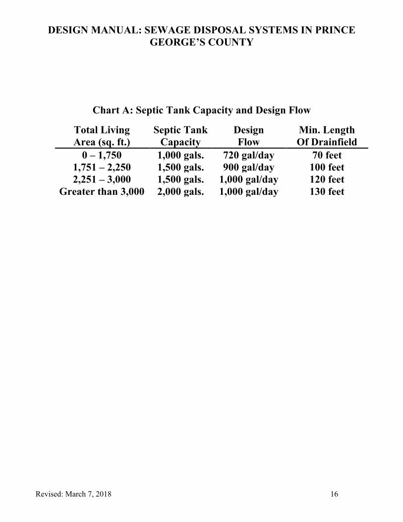
Chart A: Septic Tank Capacity and Design Flow
Total Living Septic Tank Design Min. Length Area (sq. ft.) Capacity Flow Of Drainfield
0 – 1,750 1,000 gals. 720 gal/day 70 feet 1,751 – 2,250 1,500 gals. 900 gal/day 100 feet 2,251 – 3,000 1,500 gals. 1,000 gal/day 120 feet
Greater than 3,000 2,000 gals. 1,000 gal/day 130 feet
DESIGN MANUAL: SEWAGE DISPOSAL SYSTEMS IN PRINCE GEORGE’S COUNTY
Revised: March 7, 2018 17
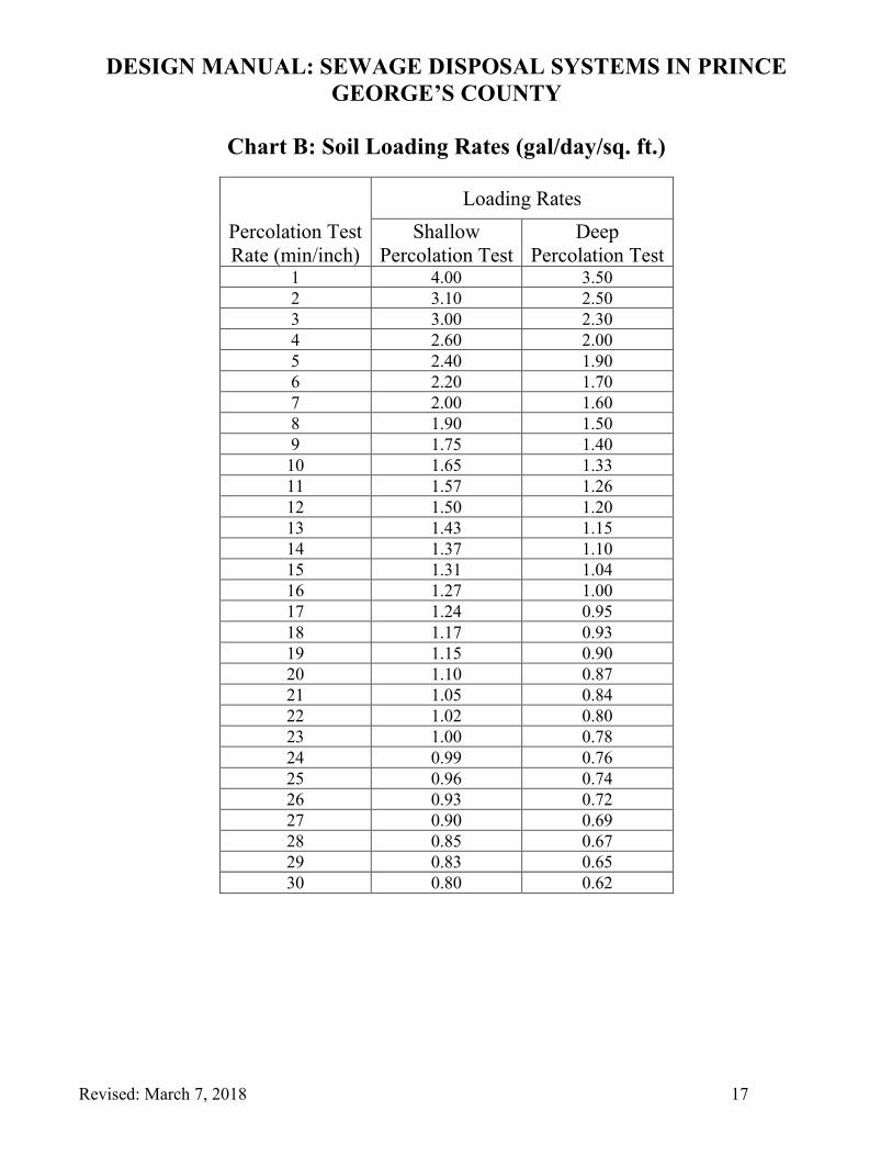
Chart B: Soil Loading Rates (gal/day/sq. ft.)
Percolation Test Rate (min/inch)
Loading Rates Shallow
Percolation Test Deep
Percolation Test 1 4.00 3.50 2 3.10 2.50 3 3.00 2.30 4 2.60 2.00 5 2.40 1.90 6 2.20 1.70 7 2.00 1.60 8 1.90 1.50 9 1.75 1.40 10 1.65 1.33 11 1.57 1.26 12 1.50 1.20 13 1.43 1.15 14 1.37 1.10 15 1.31 1.04 16 1.27 1.00 17 1.24 0.95 18 1.17 0.93 19 1.15 0.90 20 1.10 0.87 21 1.05 0.84 22 1.02 0.80 23 1.00 0.78 24 0.99 0.76 25 0.96 0.74 26 0.93 0.72 27 0.90 0.69 28 0.85 0.67 29 0.83 0.65 30 0.80 0.62
DESIGN MANUAL: SEWAGE DISPOSAL SYSTEMS IN PRINCE GEORGE’S COUNTY
Revised: March 7, 2018 18
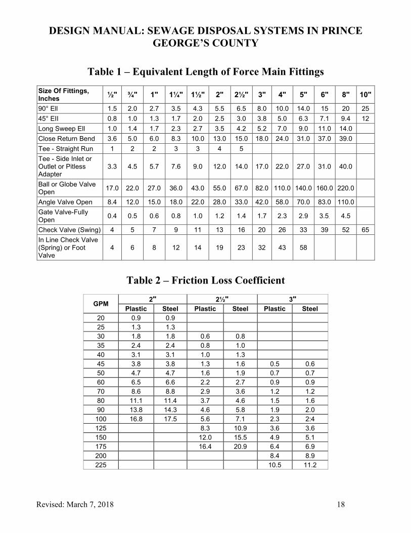
Table 1 – Equivalent Length of Force Main Fittings
Size Of Fittings, Inches ½" ¾" 1" 1¼" 1½" 2" 2½" 3" 4" 5" 6" 8" 10"
90° Ell 1.5 2.0 2.7 3.5 4.3 5.5 6.5 8.0 10.0 14.0 15 20 25 45° EII 0.8 1.0 1.3 1.7 2.0 2.5 3.0 3.8 5.0 6.3 7.1 9.4 12 Long Sweep Ell 1.0 1.4 1.7 2.3 2.7 3.5 4.2 5.2 7.0 9.0 11.0 14.0 Close Return Bend 3.6 5.0 6.0 8.3 10.0 13.0 15.0 18.0 24.0 31.0 37.0 39.0 Tee - Straight Run 1 2 2 3 3 4 5 Tee - Side Inlet or Outlet or Pitless Adapter
3.3 4.5 5.7 7.6 9.0 12.0 14.0 17.0 22.0 27.0 31.0 40.0
Ball or Globe Valve Open 17.0 22.0 27.0 36.0 43.0 55.0 67.0 82.0 110.0 140.0 160.0 220.0
Angle Valve Open 8.4 12.0 15.0 18.0 22.0 28.0 33.0 42.0 58.0 70.0 83.0 110.0 Gate Valve-Fully Open 0.4 0.5 0.6 0.8 1.0 1.2 1.4 1.7 2.3 2.9 3.5. 4.5
Check Valve (Swing) 4 5 7 9 11 13 16 20 26 33 39 52 65 In Line Check Valve (Spring) or Foot Valve
4 6 8 12 14 19 23 32 43 58
Table 2 – Friction Loss Coefficient
GPM 2" 2½" 3" Plastic Steel Plastic Steel Plastic Steel
20 0.9 0.9 25 1.3 1.3 30 1.8 1.8 0.6 0.8 35 2.4 2.4 0.8 1.0 40 3.1 3.1 1.0 1.3 45 3.8 3.8 1.3 1.6 0.5 0.6 50 4.7 4.7 1.6 1.9 0.7 0.7 60 6.5 6.6 2.2 2.7 0.9 0.9 70 8.6 8.8 2.9 3.6 1.2 1.2 80 11.1 11.4 3.7 4.6 1.5 1.6 90 13.8 14.3 4.6 5.8 1.9 2.0 100 16.8 17.5 5.6 7.1 2.3 2:4 125 8.3 10.9 3.6 3.6 150 12.0 15.5 4.9 5.1 175 16.4 20.9 6.4 6.9 200 8.4 8.9 225 10.5 11.2

DESIGN MANUAL: SEWAGE DISPOSAL SYSTEMS IN PRINCE GEORGE’S COUNTY
Revised: March 7, 2018 19
Design Data Form _____ Linear feet of drainfield _____ Volume of 4-inch drainpipe in gallons (0.65 x linear feet) _____ Diameter of force main (inches) _____ Linear feet of force main pipe _____ Equivalent length of force main pipe (add for elbows, swing check valve, tees and 6
feet of pipe in tank…24.5 for simplex and 49 for duplex plus all the bends in the force main)
_____ Total pipe length (linear + equivalent) _____ Gallons per inch drawdown: tank capacity divided by [(outlet elev. – inside tank elev.)
x 12] (Only use the “12” if numbers are in feet) _____ Gallons pumped per cycle (volume of drainfield pipe or the equivalent to a three-inch
drawdown, whichever is greater) _____ Inches drawdown per pump cycle (gals. pumped per cycle divided by gals. per inch
drawdown) _____ Drawdown in feet (inches / 12) _____ Gallons pumped per minute (15-20 gallons/lateral/minute) _____ Frictional loss per 100 feet of pipe (minimum velocity of 2 feet per second) _____ Frictional loss for system (total pipe length x frictional loss per 100 feet of pipe) _____ Static head loss (highest force main elevation – pump off elevation) _____ Total head loss (frictional loss + static head loss) _____ Gallons of reserve capacity (inlet elev. – alarm elev.) x 12 x gallons/inch drawdown _____ Required pump size (horsepower) _____ Drawdown time (gals. pumped per cycle divided by gals. pumped per min.): _____
minutes _____ seconds @ _____ gal. /min. Recommended make and model pump _____________________________ Recommended make and model control panel _______________________
(A single sewage effluent pump and simplex control panel with alarm is appropriate for residential applications, commercial projects shall use a duplex pump system.)
Elevation Data Form (feet)
_____ Inlet invert _____ Tank bottom (inside) _____ Outlet invert _____ Pump off float (19” above inside tank bottom) _____ Top of tank _____ Pump on float (Drawdown per pump Cycle in feet added to “Off Float”) _____ Tank bottom (outside) _____ Alarm float (6” above “On Float”)
DESIGN MANUAL: SEWAGE DISPOSAL SYSTEMS IN PRINCE GEORGE’S COUNTY
Revised: March 7, 2018 20
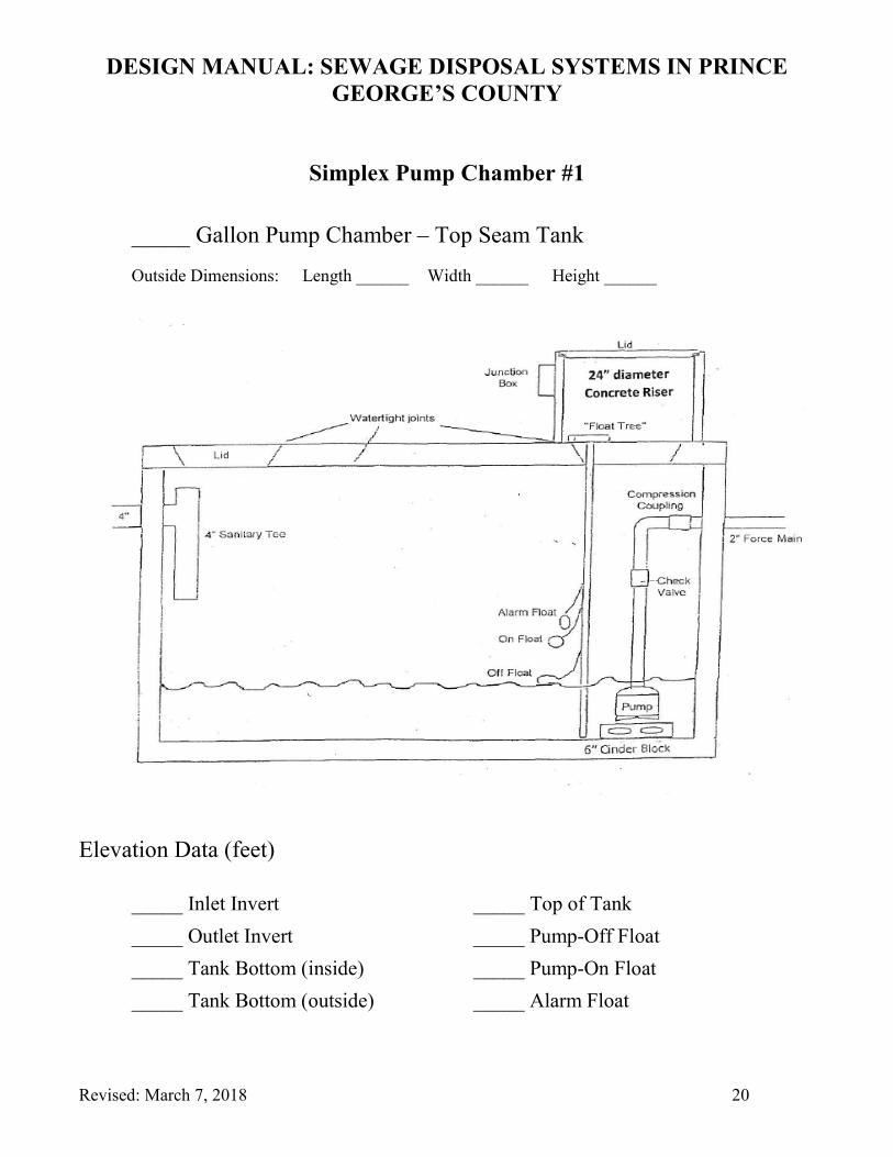
Simplex Pump Chamber #1
_____ Gallon Pump Chamber – Top Seam Tank
Outside Dimensions: Length ______ Width ______ Height ______
Elevation Data (feet)
_____ Inlet Invert _____ Top of Tank _____ Outlet Invert _____ Pump-Off Float _____ Tank Bottom (inside) _____ Pump-On Float _____ Tank Bottom (outside) _____ Alarm Float
DESIGN MANUAL: SEWAGE DISPOSAL SYSTEMS IN PRINCE GEORGE’S COUNTY
Revised: March 7, 2018 21
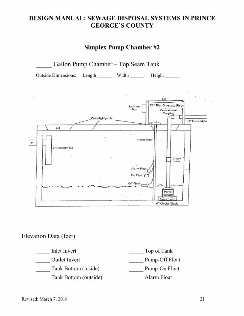
Simplex Pump Chamber #2
_____ Gallon Pump Chamber – Top Seam Tank
Outside Dimensions: Length ______ Width ______ Height ______
Elevation Data (feet)
_____ Inlet Invert _____ Top of Tank _____ Outlet Invert _____ Pump-Off Float _____ Tank Bottom (inside) _____ Pump-On Float _____ Tank Bottom (outside) _____ Alarm Float
DESIGN MANUAL: SEWAGE DISPOSAL SYSTEMS IN PRINCE GEORGE’S COUNTY
Revised: March 7, 2018 22
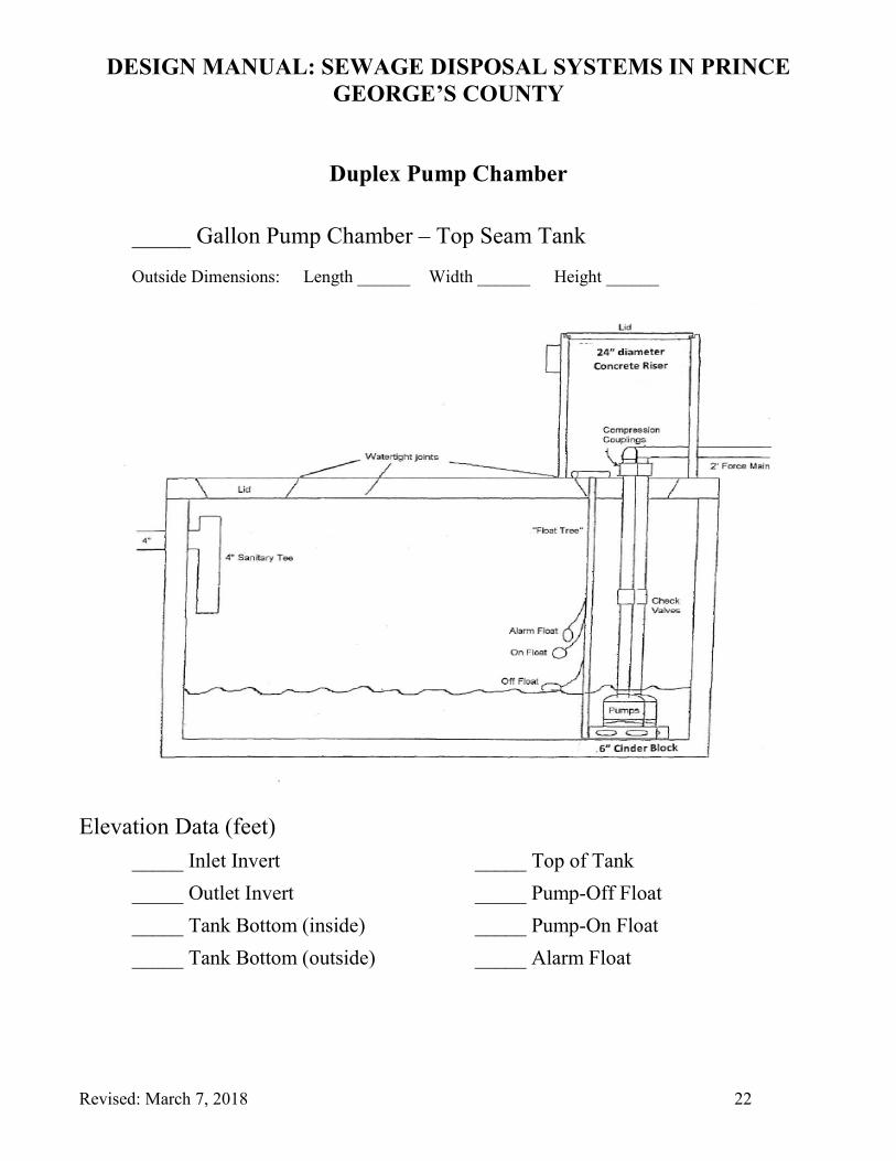
Duplex Pump Chamber
_____ Gallon Pump Chamber – Top Seam Tank
Outside Dimensions: Length ______ Width ______ Height ______
Elevation Data (feet) _____ Inlet Invert _____ Top of Tank _____ Outlet Invert _____ Pump-Off Float _____ Tank Bottom (inside) _____ Pump-On Float _____ Tank Bottom (outside) _____ Alarm Float
DESIGN MANUAL: SEWAGE DISPOSAL SYSTEMS IN PRINCE GEORGE’S COUNTY
Revised: March 7, 2018 23
Pump Chamber Installation Procedures
An electrical permit is required to install the effluent pump motor, alarm box and associated wiring. A copy of the electrical permit displaying approval by the electrical inspector must be on site for Health Department review. The Health Department shall not conduct the pump system test until the electrical inspector has approved the electrical components of the pump system.
1. The Health Department must approve any changes to the approved sewage disposal system plans. Contact the Health Department prior to purchasing or installing any components not specified on the approved plans.
2. If ground water is observed during the excavation for the Septic tank or pump chamber, stop digging and contact the Health Department. Do not install a tank in the groundwater until the Environmental Health Specialist has evaluated the site and given permission to proceed with the installation.
3. The electrical junction box serving the pump motor and floats must be located outside the tank chamber and be a minimum of six inches above finished grade. The pump and alarm floats must be placed on separate electrical circuits.
4. All septic tank, pump chamber and access ring seams shall be made watertight. The force main shall be constructed of solvent welded schedule 40 PVC or equivalent. The pump chamber riser must be at least 24 inches in diameter and extend no less than six inches above final grade.
5. Attach the floats to a schedule 40 PVC float tree that can be easily removed for service or adjustment. Do not attach the floats to the force main.
6. The Health Department shall observe the pump system operate through a normal operating cycle. Have the system fully checked and run through several cycles prior to requesting a final Health Department inspection. Testing the system without water is not acceptable.
7. Inspection for leakage of the force main fittings will be made during the pump test procedure. 8. Contact the Health Department Environmental Protection/Policy Program (301-883-7681) if you
have any questions concerning the above requirements.
DESIGN MANUAL: SEWAGE DISPOSAL SYSTEMS IN PRINCE GEORGE’S COUNTY
Revised: March 7, 2018 24
Percolation Test Report (Gravity System)
DESIGN MANUAL: SEWAGE DISPOSAL SYSTEMS IN PRINCE GEORGE’S COUNTY
Revised: March 7, 2018 25
Gravity Flow Site Plan
DESIGN MANUAL: SEWAGE DISPOSAL SYSTEMS IN PRINCE GEORGE’S COUNTY
Revised: March 7, 2018 26
Gravity Flow Septic Profile
DESIGN MANUAL: SEWAGE DISPOSAL SYSTEMS IN PRINCE GEORGE’S COUNTY
Revised: March 7, 2018 27
Percolation Test Report (Effluent Pump System)
DESIGN MANUAL: SEWAGE DISPOSAL SYSTEMS IN PRINCE GEORGE’S COUNTY
Revised: March 7, 2018 28
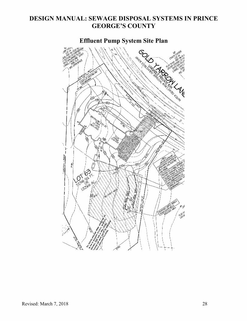
Effluent Pump System Site Plan
DESIGN MANUAL: SEWAGE DISPOSAL SYSTEMS IN PRINCE GEORGE’S COUNTY
Revised: March 7, 2018 29
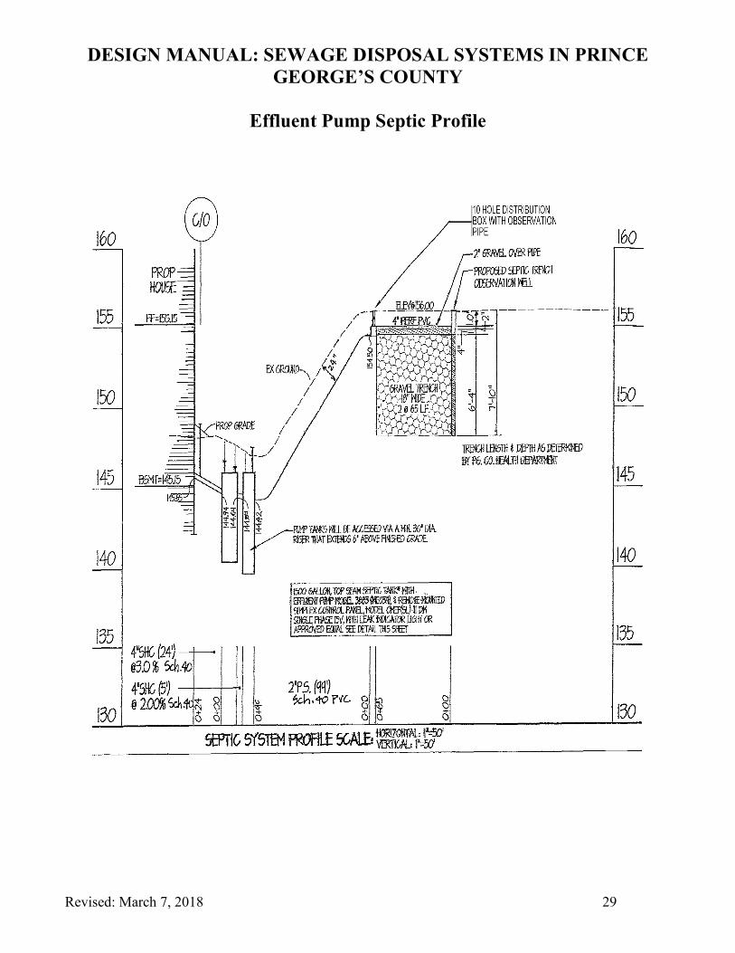
Effluent Pump Septic Profile
DESIGN MANUAL: SEWAGE DISPOSAL SYSTEMS IN PRINCE GEORGE’S COUNTY
Revised: March 7, 2018 30
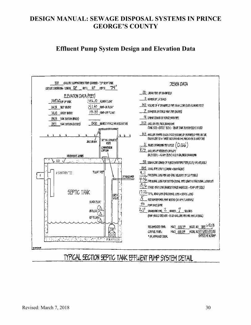
Effluent Pump System Design and Elevation Data

DESIGN MANUAL: SEWAGE DISPOSAL SYSTEMS IN PRINCE GEORGE’S COUNTY
Revised: March 7, 2018 31