Embed Size (px)
DESCRIPTION
The Ayre AX-5 Integrated Amplifier
Citation preview
t: 01727 865488 e: [email protected] w: www.symmetry-systems.co.uk
Symmetry, Suite 5, 17 Holywell Hill, St Albans, Hertfordshire AL1 1DT
The AX-5from Ayre Acoustics
Press ReleaseAugust 2013
Words by Charles Hansen:
The NEW AX-5 from Ayre Acoustics is an integrated amp, often called a “control amp”. Now there are many waysto combine different components into one box. This isan entire subject unto itself.
There are lots of possible variations on combining separate functions into one box. Some make more sense to me than others. In the old days receivers were quite popular, but now radio is kind of a dead medium. And of course no receiver could ever match the audio performance of good separate components.
(I’ve always been tempted to make an FM tuner, but it’s hard to make anything of quality in the US for less than $2000 or $3000. By “quality” I mean discrete balanced circuits. For that much money most people would expect incredible RF performance and that is something I currently don’t know that much about. The thing that keeps me from learning RF design and doing a tuner anyway is the death of good FM stations and the ever-impending threat of analog FM being replaced altogether by some silly compressed digital format. And remember that the Marantz 10B tuner is what drove the original company to near bankruptcy and forced Saul to sell it to Superscope, who basically ruined everything.)Back to the original question. I think that putting too
many things into one box (eg, phono stage, DAC, preamp, and power amp) would lead to a product that would be relatively expensive *and* degrade the overall performance. Amplifying microvolt level MC phono signals in a box that is also delivering tens of amperes to loudspeakers is not conducive to high performance. Similarly, putting complex digital circuitry in the same box with analog circuitry is going to cause problems. The RFI from the digital circuits is going to contaminate the analog signals.
" So to my way of thinking the best route to reducing the overall number of boxes in your system is an integrated amp (combining the two analog components into one box) and then a separate box for the digital (either a disc player or a DAC). "But even putting a phono stage into an integrated is
Ayre AX-5 IntroductionFeaturing Ayre's new Diamond output stage, their exclusive EquiLock circuitry, and a Shallco solid-silver contact switch for gain control, this fully-discrete, fully-balanced, zero-feedback integrated amplifier provides a complete solution for your modern music system. The key to perfecting the AX-5 was to incorporate the Variable Gain Technology (VGT) of the award-winning Ayre KX-R preamplifier into the power amplifier section. The addition of ultra-transparent FET input selector switches completed the transformation of a basic power amplifier into a compact one-box solution which will become the heart of your high-performance audio system.
UK PRICE: Silver £7,895**add £180 for black chassis
TYPE: Reference class integrated amplifier
OUTPUT POWER: 125 wpc 8 ohms / 250 wpc 4 ohms
DIMENSIONS: w 44cm x d 48cm x h 12cm
WEIGHT: 22 kg
AVAILABILITY: Now
MANUFACTURER: Ayre Acoustics
WEB SITE: www.ayre.com
t: 01727 865488 e: [email protected] w: www.symmetry-systems.co.uk
Symmetry, Suite 5, 17 Holywell Hill, St Albans, Hertfordshire AL1 1DT
Page 2
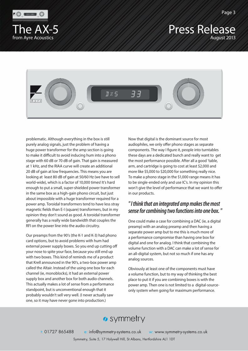
problematic. Although everything in the box is still purely analog signals, just the problem of having a huge power transformer for the amp section is going to make it difficult to avoid inducing hum into a phono stage with 60 dB or 70 dB of gain. That gain is measured at 1 kHz, and the RIAA curve will create an additional 20 dB of gain at low frequencies. This means you are looking at least 80 dB of gain at 50/60 Hz (we have to sell world-wide), which is a factor of 10,000 times! It’s hard enough to put a small, super-shielded power transformer in the same box as a high-gain phono circuit, but just about impossible with a huge transformer required for a power amp. Toroidal transformers tend to have less stray magnetic fields than E-I (square) transformers, but in my opinion they don’t sound as good. A toroidal transformer generally has a really wide bandwidth that couples the RFI on the power line into the audio circuitry.
Our preamps from the 90’s (the K-1 and K-3) had phono card options, but to avoid problems with hum had external power supply boxes. So you end up cutting off your nose to spite your face, because you still end up with two boxes. This kind of reminds me of a product that Krell announced in the 90’s, a two-box power amp called the Altair. Instead of the using one box for each channel (ie, monoblocks), it had an external power supply box and another box for both audio channels. This actually makes a lot of sense from a performance standpoint, but is unconventional enough that it probably wouldn’t sell very well. (I never actually saw one, so it may have never gone into production.)
Now that digital is the dominant source for most audiophiles, we only offer phono stages as separate components. The way I figure it, people into turntables these days are a dedicated bunch and really want to get the most performance possible. After all a good ‘table, arm, and cartridge is going to cost at least $2,000 and more like $5,000 to $20,000 for something really nice. To make a phono stage in the $1,000 range means it has to be single-ended only and use IC’s. In my opinion this won’t give the level of performance that we want to offer in our products.
" I think that an integrated amp makes the most sense for combining two functions into one box. "One could make a case for combining a DAC (ie, a digital preamp) with an analog preamp and then having a separate power amp but to me this is much more of a performance compromise than having one box for digital and one for analog. I think that combining the volume function with a DAC can make a lot of sense for an all-digital system, but not so much if one has any analog sources.
Obviously at least one of the components must have a volume function, but to my way of thinking the best place to put it if you are combining boxes is with the power amp. Then one is not limited to a digital-source-only system when going for maximum performance.
t: 01727 865488 e: [email protected] w: www.symmetry-systems.co.uk
Symmetry, Suite 5, 17 Holywell Hill, St Albans, Hertfordshire AL1 1DT
t: 01727 865488 e: [email protected] w: www.symmetry-systems.co.uk
Symmetry, Suite 5, 17 Holywell Hill, St Albans, Hertfordshire AL1 1DT
The AX-5from Ayre Acoustics
Press ReleaseAugust 2013
Page 3
But there is probably a big enough customer base for digital-source-only systems that some day we may build a DAC with a volume control. One big advantage of doing this is that one can make a high quality volume control for significantly less cost. The reason is that a purely digital volume control is practically free, but it degrades the sound quality more and more as the volume is reduced. But with only digital sources, one could make a hybrid volume control. A good approach would be to have (say) six small (eg, 1 dB steps) digitally.
Then the maximum degradation would only be one bit. In a 24-bit system this would still leave 23 bits of performance, which is more than enough. (Any real-world system is limited to only 20 or *maybe* 21 bits of resolution.) Then the analog volume control would only need coarse steps of 6 dB. This means a 12-position switch would be more than enough, and that is a *lot* cheaper than (for example) the 60-position switch we use in our KX-R analog preamp.
Another problem with putting too many functions into one box is the lack of ability to upgrade. For example, Linn makes some boxes that have everything in them but the speakers. This is a nice solution for a less-than-maximum performance system, such as a second system for the bedroom or office. But then there are severe price constraints.
People might pay $2,000 or $3,000 for a relatively limited performance system with no way to upgrade over time, but not a lot more than that. Again that means using single-ended circuitry, IC’s, and possibly class-D power amps. These are all things that don’t appeal to me. That doesn’t mean that some company shouldn’t make them or that customers shouldn’t buy them. It’s just not the approach that we like to take.
It’s kind of like tubed products. They can sound great and all, but they’re not something that I particularly want to own, or design, or manufacture. But it all works out because there are other companies that *do* take that approach and meet the needs of customers that want to go in that direction. No company can be all things to all people, and one needs to decide on the approach that is “comfortable” to them.
“ I guess the bottom line is that to me, what you are asking for is not really an ‘integrated amp’ so much as an “integrated system. ”
We will surely offer more integrated amps in the future besides our current AX-7 and quite possibly a DAC with a volume control for digital-source-only systems, but I don’t foresee us ever building an integrated system. A very long-winded answer, but I hope that helps you understand where we are coming from. So there is a (very long-winded) explanation of why our integrated amp still retains the basic feature set of a traditional integrated amp, and why we don’t include digital inputs, or phono stages, or whatever strange combinations of things that some customers ask for.
I’m not saying that those aren’t valid for some situations or that they won’t make some customers happy. I’m just saying that they don’t meet the requirements that Ayre is aiming for and that if they are looking for something like that they should look at other brands. Back to the design of the AX-5.
Before I go on, I want to clarify something from a previous e-mail. Towards the end I was speaking about an Australian amplifier that all the reviewers agreed sounded different from any other amplifier they had ever heard. (I was referring, of course, to the Halcro.) What I neglected to mention (probably because I tend to take it for granted that everybody knows these things) is that the reason the Halcro had such ridiculously low distortion was because it used ridiculously high levels of negative feedback.
It is understandable that the average person would not know that this is the case, because their advertising on this point was EXTREMELY misleading. But that amplifier had more feedback (probably by at least a factor of 10x) than any other amplifier ever designed. For example one of the features of this amplifier was the so-called “error correcting” output stage.
The way that an “error correcting” (EC) output stage
t: 01727 865488 e: [email protected] w: www.symmetry-systems.co.uk
Symmetry, Suite 5, 17 Holywell Hill, St Albans, Hertfordshire AL1 1DT
t: 01727 865488 e: [email protected] w: www.symmetry-systems.co.uk
Symmetry, Suite 5, 17 Holywell Hill, St Albans, Hertfordshire AL1 1DT
The AX-5from Ayre Acoustics
Press ReleaseAugust 2013
Page 4
5
works goes far beyond the normal use of negative feedback. Instead of simply comparing the output signal to the input signal and subtracting the difference (ie, the error), the EC output stage AMPLIFIES the error signal (ie, the feedback) before applying it! Some people would like to do this to the entire amplifier but it is not possible in actual practice. When the EC technique is used around just one stage (eg, the output stage), it can be made to work. But if one tried to use the EC technique around the entire amplifier circuit comprising multiple stages, there would be enough combined phase shift from all of the stages that at some point the negative feedback would become *positive* feedback and you would have a 300 watt oscillator on your hands that would likely self-destruct in a few tens of milliseconds, taking out your loudspeakers in the process.
OK, so now we have created an integrated amp that is truly revolutionary in its concept and execution. We have described how the input selector works and why we have chosen FET switches (properly implemented) to achieve the most transparent input selection short of the Shallco rotary switches but managed to save thousands of dollars off the retail price by making only a *very, very* small sacrifice in the sound quality.
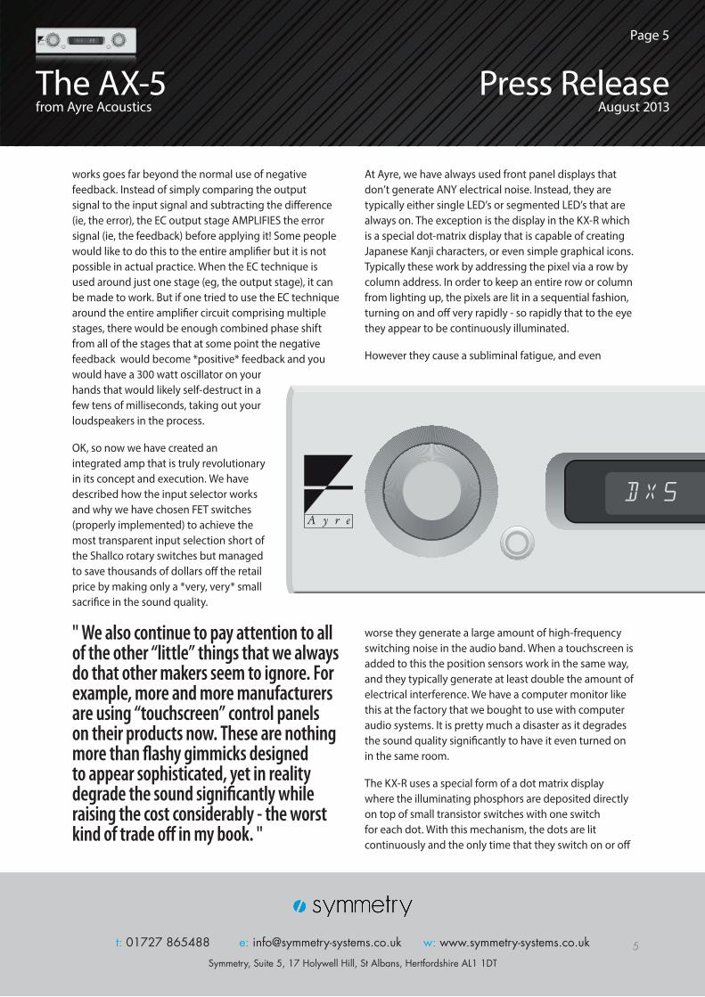
" We also continue to pay attention to all of the other “little” things that we always do that other makers seem to ignore. For example, more and more manufacturers are using “touchscreen” control panels on their products now. These are nothing more than flashy gimmicks designed to appear sophisticated, yet in reality degrade the sound significantly while raising the cost considerably - the worst kind of trade off in my book. "
At Ayre, we have always used front panel displays that don’t generate ANY electrical noise. Instead, they are typically either single LED’s or segmented LED’s that are always on. The exception is the display in the KX-R which is a special dot-matrix display that is capable of creating Japanese Kanji characters, or even simple graphical icons. Typically these work by addressing the pixel via a row by column address. In order to keep an entire row or column from lighting up, the pixels are lit in a sequential fashion, turning on and off very rapidly - so rapidly that to the eye they appear to be continuously illuminated.
However they cause a subliminal fatigue, and even
worse they generate a large amount of high-frequency switching noise in the audio band. When a touchscreen is added to this the position sensors work in the same way, and they typically generate at least double the amount of electrical interference. We have a computer monitor like this at the factory that we bought to use with computer audio systems. It is pretty much a disaster as it degrades the sound quality significantly to have it even turned on in the same room.
The KX-R uses a special form of a dot matrix display where the illuminating phosphors are deposited directly on top of small transistor switches with one switch for each dot. With this mechanism, the dots are lit continuously and the only time that they switch on or off
t: 01727 865488 e: [email protected] w: www.symmetry-systems.co.uk
Symmetry, Suite 5, 17 Holywell Hill, St Albans, Hertfordshire AL1 1DT
t: 01727 865488 e: [email protected] w: www.symmetry-systems.co.uk
Symmetry, Suite 5, 17 Holywell Hill, St Albans, Hertfordshire AL1 1DT
The AX-5from Ayre Acoustics
Press ReleaseAugust 2013
Page 5
is when the display is changed (eg, when changing the volume setting). Of course everything is a trade off and the trade off here is cost. What would be a simple $10 part in the standard multiplexed configuration suddenly becomes a $200 part to achieve noise-free operation.
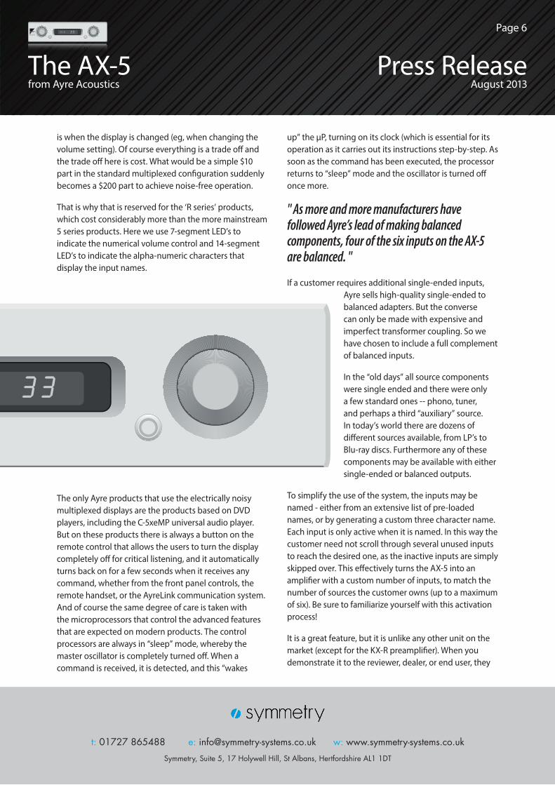
That is why that is reserved for the ‘R series’ products, which cost considerably more than the more mainstream 5 series products. Here we use 7-segment LED’s to indicate the numerical volume control and 14-segment LED’s to indicate the alpha-numeric characters that display the input names.
The only Ayre products that use the electrically noisy multiplexed displays are the products based on DVD players, including the C-5xeMP universal audio player. But on these products there is always a button on the remote control that allows the users to turn the display completely off for critical listening, and it automatically turns back on for a few seconds when it receives any command, whether from the front panel controls, the remote handset, or the AyreLink communication system.And of course the same degree of care is taken with the microprocessors that control the advanced features that are expected on modern products. The control processors are always in “sleep” mode, whereby the master oscillator is completely turned off. When a command is received, it is detected, and this “wakes
up” the µP, turning on its clock (which is essential for its operation as it carries out its instructions step-by-step. As soon as the command has been executed, the processor returns to “sleep” mode and the oscillator is turned off once more.
" As more and more manufacturers have followed Ayre’s lead of making balanced components, four of the six inputs on the AX-5 are balanced. "
If a customer requires additional single-ended inputs, Ayre sells high-quality single-ended to balanced adapters. But the converse can only be made with expensive and imperfect transformer coupling. So we have chosen to include a full complement of balanced inputs.
In the “old days” all source components were single ended and there were only a few standard ones -- phono, tuner, and perhaps a third “auxiliary” source. In today’s world there are dozens of different sources available, from LP’s to Blu-ray discs. Furthermore any of these components may be available with either single-ended or balanced outputs.
To simplify the use of the system, the inputs may be named - either from an extensive list of pre-loaded names, or by generating a custom three character name. Each input is only active when it is named. In this way the customer need not scroll through several unused inputs to reach the desired one, as the inactive inputs are simply skipped over. This effectively turns the AX-5 into an amplifier with a custom number of inputs, to match the number of sources the customer owns (up to a maximum of six). Be sure to familiarize yourself with this activation process!
It is a great feature, but it is unlike any other unit on the market (except for the KX-R preamplifier). When you demonstrate it to the reviewer, dealer, or end user, they
t: 01727 865488 e: [email protected] w: www.symmetry-systems.co.uk
Symmetry, Suite 5, 17 Holywell Hill, St Albans, Hertfordshire AL1 1DT
The AX-5from Ayre Acoustics
Press ReleaseAugust 2013
Page 6
are invariably fascinated by this level of customization. But if you are not familiar with how it works, you may look a bit of the fool while trying to get the system to emit sounds!
For dealer showrooms, we normally recommend activating all of the inputs and simply labelling then “IN1” through “ IN6” so that when components are switched around (as they inevitably are) the system is always ready to produce music. However, a nice part of the demonstration is to show how simple it is to change the name of an input or to disable it altogether.
The included remote control is our custom metal remote. This has a slew of great unique features. One is that the keypad is back lit for easy operation in a darkened room. Using a single LED to illuminate the entire front panel via a system of optical fibres, the button to activate the illumination is physically off by itself so that it can be found simply by feel even in a pitch-dark room.
The handset also has controls for a disc player or transport. It is easily configured to operate the CX-7 CD player (Philips RC-5 codes), D-1, DX-7 DVD players, C-5xe universal stereo player (Pioneer codes), or DX-5 universal audio engine (Oppo codes).
" Finally it has Ayre’s exclusive Battery Saver function. If the handset becomes wedged in the couch cushions and one of the buttons is accidentally pressed for a long period of time, it will not drain the battery. Instead after any key is held for more than ten seconds continuously, the internal µP will go to “sleep” and save the batteries. "To comply with the recent low-power regulations enacted by the EU, the unit has a combination master power switch and magnetic circuit-breaker. No more looking for replacement fuses when the shops are all closed. Furthermore the breaker chosen for the AX-5 is not the commonplace thermal breaker that has non-linear metal alloys chosen for their thermal expansion
properties. It is a hydraulically-damped magnetic circuit breaker, where the AC mains power is fed through a coil of pure copper wire. Excessive current draw creates a magnetic field that opens the electrical contacts, providing not only the best sound quality, but also the most reliable and repeatable protective action.
The right-hand front panel button has two functions. A short press places the unit into mute mode, indicated by illuminating the decimal points in the LED display. Pressing and holding the button for more than three seconds, places the unit into “low-power consumption mode”, indicated by the green LED ring on the push button.
In this state, the bias is removed from the output stage, reducing the power consumption by a factor of approximately 10x, the audio is muted, and the display is turned off. However, the AyreLink function are still operable, as are the tape out connectors. In this day and age, the tape out connectors will more commonly be used to connect the source components to a headphone amplifier, thereby allowing the preamplifier functions to be controlled while the power amplifier section is effectively turned off. However the voltages remain applied to the audio circuitry allowing for a quick warm-up.
Pressing and holding the right-hand button also sends a signal out on the AyreLink connectors on the rear panel. Levinson was probably the first to introduce a communication system so that a stack of separate components could be configured to act as one large system. But the AyreLink system takes this to a completely new level.
For starters, the connecting cables are two-line telephone cables (available at any RadioShack in just about any length and in three different colours for only a few dollars). Sometimes these are not used in other countries, but we include something with every AyreLink product and are happy to get anything specific that you may need. Next, there are two connectors on each unit. Each connector has both an input and an output, so they are completely interchangeable. The system is connected in a “daisy-chain” fashion, and the component that generates the command transmits it
t: 01727 865488 e: [email protected] w: www.symmetry-systems.co.uk
Symmetry, Suite 5, 17 Holywell Hill, St Albans, Hertfordshire AL1 1DT
t: 01727 865488 e: [email protected] w: www.symmetry-systems.co.uk
Symmetry, Suite 5, 17 Holywell Hill, St Albans, Hertfordshire AL1 1DT
The AX-5from Ayre Acoustics
Press ReleaseAugust 2013
Page 7
on both connectors. As it travels down the line, any component that is supposed to react to the command does so and re-sends the command down the line. If it does *not* need to act on the command, it simply re-transmits it until all of the units have received the command. There are no requirements for connecting things in a certain order or configuring anything -- just plug’n’play.
But the best thing about the AyreLink system is that each input has an opto-isolator. This means that adding the AyreLink cables will never cause a ground loop, nor couple any high-frequency noise from one component to another. There is absolutely no degradation of the audio signal from using the AyreLink system - just added convenience.
" The Diamond circuit has been around for a long time. Specifically, it was developed and patented in the US in the 1960’s, but for use in digital switching circuits. "I could never figure out why it was called a “Diamond” circuit, as it really looks nothing at all like a diamond the way it is normally drawn. For example, here is how they show it from Burr-Brown on a now discontinued part - see page 9, diagram 1.
There are some extra parts shown in here, with the current sources and some other bits, but there isn’t anything particularly “diamond-like” about it.
If you take away all of the extra parts and strip the circuit down to its bare essentials, it looks like this - see page 9, diagram 2.
Now it is much easier to understand. It is simply a pair of complementary cross-coupled emitter-followers. However, it still makes no sense to me why in the world it would be called a “diamond” buffer. But I am an amateur historian of audio technology and audio companies. So I kept digging...
Then I found the original patent for the circuit. It was invented by a professor at MIT, Richard H. Baker, who is best known for the “Baker clamp”, a circuit that prevents problems when a transistor amplifier clips. (Although Baker patented it and his name is associated with it, the circuit was actually known for several years before he applied for the patent.)
Back to the “Diamond” buffer. Professor Baker developed another circuit which he called “The “Diamond Circuit” in an internal publication for MIT, but on the patent he called it “A Gateable Bridge Network Having Power Gain” (attached), with some properties that mad it sort of a hybrid between a digital circuit and an analog circuit. In the patent application, Baker drew it rather differently than it is normally drawn and one can now *easily* see why he called it a “Diamond Circuit” - see page 9, diagram 3.
Diagram 3 is simply a rearranged version of the simplified circuit above, but when drawn in this manner it is obvious to see why Baker called it the “Diamond Circuit”. In actual practice it was most useful as a “buffer” -- that is, a circuit with no voltage gain but a high current gain, which is precisely what is needed to drive a low impedance load. Hence it has become popularly known as a “Diamond buffer”.
It is commonly used in the output stage of “buffer” IC’s that have unity voltage gain, but boost the current to drive heavier loads. Sometimes it is also used with discrete circuits, where it requires careful matching of the opposite polarities of parts (NPN and PNP) to minimize the offset voltages.It is typically only used in low power stages, such as preamplifiers outputs or things of that nature. After playing around with it for quite a while I came to understand why this is so. To work properly, the driver stage needs to use an identical transistor to the output stage.
An output transistor is a big beast that typically draws a lot of current at idle and also has large
t: 01727 865488 e: [email protected] w: www.symmetry-systems.co.uk
Symmetry, Suite 5, 17 Holywell Hill, St Albans, Hertfordshire AL1 1DT
t: 01727 865488 e: [email protected] w: www.symmetry-systems.co.uk
Symmetry, Suite 5, 17 Holywell Hill, St Albans, Hertfordshire AL1 1DT
The AX-5from Ayre Acoustics
Press ReleaseAugust 2013
Page 8
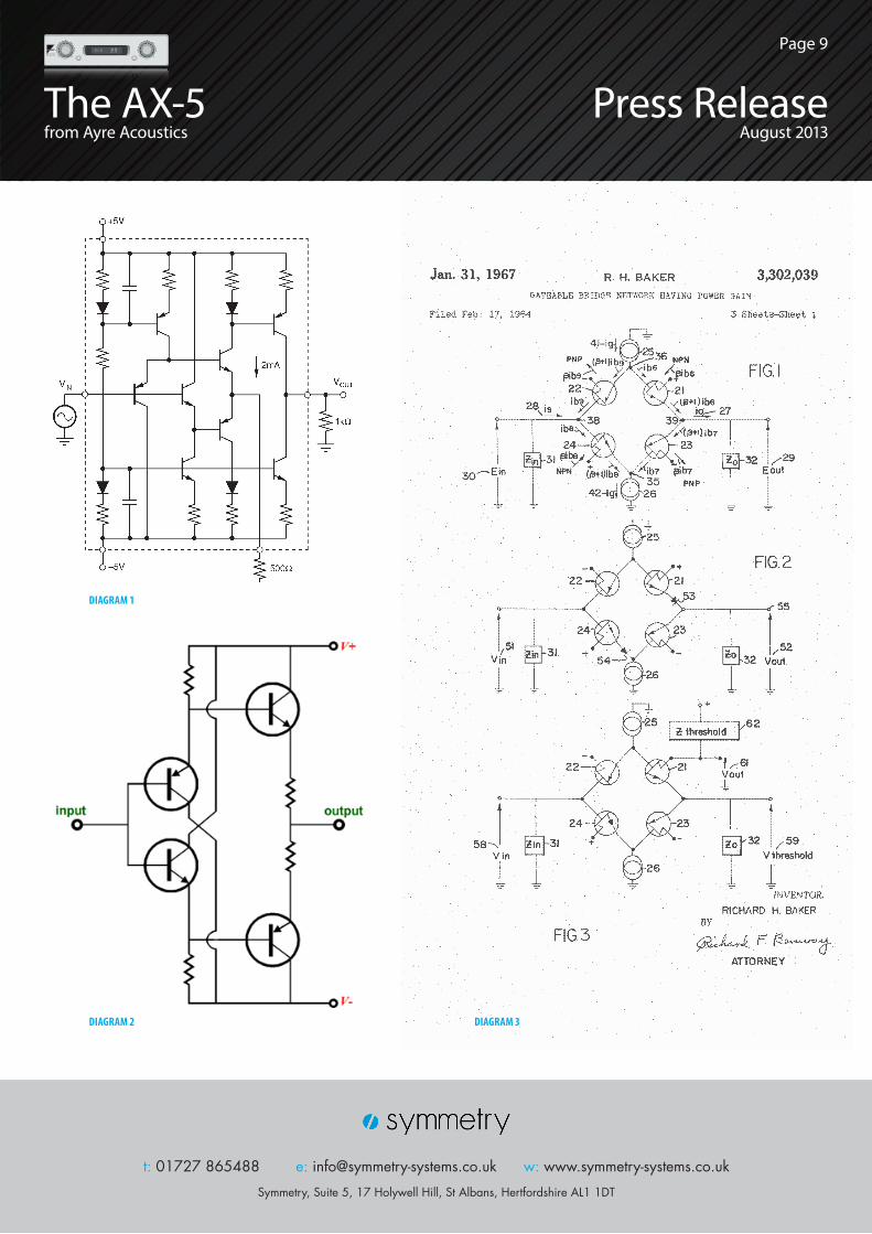
DIAGRAM 1
DIAGRAM 2 DIAGRAM 3
t: 01727 865488 e: [email protected] w: www.symmetry-systems.co.uk
Symmetry, Suite 5, 17 Holywell Hill, St Albans, Hertfordshire AL1 1DT
t: 01727 865488 e: [email protected] w: www.symmetry-systems.co.uk
Symmetry, Suite 5, 17 Holywell Hill, St Albans, Hertfordshire AL1 1DT
The AX-5from Ayre Acoustics
Press ReleaseAugust 2013
Page 9
capacitances between the terminals. So this means that the driver stage also has to use a “big beast” and this stage also needs to draw a lot of current and is fairly difficult to drive due to the large capacitances.
Using a diamond buffer as an output stage has two fairly significant disadvantages:
1) It draws a lot of current and this adds to the total power consumption (from the wall outlet) of the amplifier, as well as requires additional heatsinking to dissipate the power drawn by the driver stage.
2) Since the input transistors of the diamond buffer must be identical to the output transistors of the diamond buffer, they are large and rather difficult to drive. This means that one cannot drive them directly with the typical voltage amplifier used to provide the gain in a power amplifier circuit.
To address the first problem means that the amplifier needs to be larger and heavier, with a more powerful power supply. To address the second problem means that one needs to use a more powerful driving source than the typical amplifier uses.
The large majority of transistor power amplifiers use a “front end” circuit that provides the voltage gain, and then an “output stage” with no voltage gain, but that provides the current gain required to drive the low impedance of the loudspeakers. (One version of the Wilson WATT/Puppy dipped to around 0.3 ohms in the upper midrange. While this is unusual, it is important that a high-quality power amp won’t be bothered by loads below 2 ohms or even 1 ohm. Most electrostatic loudspeakers drop below 1 ohm at frequencies above 20 kHz.)
The typical solid-state power amplifier only uses two transistors signal path of the output stage. (There may be more in parallel to provide more current *handling* capability, but this does NOT increase the current gain.) A really good output transistor will have a current gain of around 100x, and the same is true of a driver transistor. This means that a two-transistor output stage will have a current gain of 100 x 100 = 10,000x. So if you connect a
4 ohm loudspeaker, the load on the “front end” (voltage gain stage) will be 40,000 ohms.
While this sounds like a lot, it really isn’t. It is a low enough load that it puts a strain on the front end and increases the distortion significantly. The solution that 99.9% of all designer use is to add loop negative feedback. Works great on paper, but doesn’t sound so great.
“ At Ayre, we have always used *three* transistors in series in our output stage. “
So if the third transistor also has a current gain of 100x, now the total current gain is 100 x 100 x 100 = 1,000,000x. Now if you connect the 4 ohm speaker, it only puts a load of 4 megohms on the front end and the distortion drops dramatically without having to use negative feedback. These extra transistors only add a dollar or so to the Bill of Material (BOM) so unless we are talking ultra-cheap junk audio equipment, this is completely negligible.
" Back to the Diamond circuit. If it has these disadvantages, why in the world would anyone use it? The short answer is it sounds better. "The long answer is that I really don’t know why, which doesn’t help much as that’s not much of a story to tell, and writers like to tell stories and people like to listen to stories. At this point the best that I can do is to speculate. So here goes nothing....
Before transistors came along (in the vacuum tube era) there were two types of power amplifier circuits in common use. One was the single-ended circuit and the other was the push-pull circuit. In the single-ended circuit, there is one tube (or possibly more, but they are simply connected in parallel to act as one larger tube), and this tube must be “on” all the time or the signal will be horribly distorted with clipping on either the top or
t: 01727 865488 e: [email protected] w: www.symmetry-systems.co.uk
Symmetry, Suite 5, 17 Holywell Hill, St Albans, Hertfordshire AL1 1DT
The AX-5from Ayre Acoustics
Press ReleaseAugust 2013
Page 10
the bottom (depending on the particulars of the design.
This limits the power to a few watts (“flea-power”) unless the designer resorts to huge power tubes originally designed for radio station transmitting tubes. Even then it is hard to get more than 20 (or *maybe* 25) watts out of the amp and it draws a ton of juice from the wall, which is pumped out as heat in your listening room.
So when the push-pull output stage was invented, it allowed for MUCH more powerful amplifiers to be built very easily. Instead of a single 6L6 tube putting out perhaps 5 watts, a pair in push-pull could easily put out 30 watts. And when they developed bigger tubes like the KT-88 (6550 in the US), instead of a single tube putting out maybe 8 watts, a pair could put out 60 watts! This was just in time for stereo, when all of a sudden one needed TWO speakers and the small “acoustic suspension” designs took over the market place. They needed all that power, as they were so inefficient.With a push-pull amplifier, the input signal is split into two halves with opposite polarities with a stage called a “phase-splitter”. Then each output tube amplifies one half of the signal, and these two “half-signals” are recombined by the output transformer.
When solid-state came out, they were able (eventually) to make two devices that were opposite and (approximately) equal. So a designer could pull the same trick of splitting the signal into two parts, one for each output transistor, and then the output of each output transistor was combined back into a single output containing the entire signal without the need for an output transformer (which is big, heavy, and very expensive). This type of design is referred to as a “complementary output stage”.
One can also do the same trick with transistors of the same polarity by adding an extra transistor to invert the drive signal to one of the output transistors, and this is called a “quasi-complementary output stage”, but it doesn’t change anything fundamental about the situation.
Specifically, the input signal on ANY modern power amplifier is split into two parts, sent through an
output stage that has a separate device for each half of the signal, and then the two half-output signals are recombined to make one final output signal. This is true whether it is tube or transistor, uses transformers or is or not, is truly complementary or quasi-complementary.
" What is different about the diamond buffer from a typical output stage is that after the signal has been split into two halves to send to each output device, is that the two half signals are rejoined at ONE single point. There is NOTHING in between these two half signals. "A conventional output stage always has *something* in between the two inputs of the two half-output stages
before they are recombined. Typically it is a bias circuit of some sort that sets the idling current in the output devices. but there is *always* something there.
The diamond circuit is the only commonly output stage in use that feeds the two half-output-stages from the same exact point. In contrary, here is a typical two-transistor NON-diamond output stage. (Two transistors for each half of the signal, for a total of four transistors) - see page 13, diagram 4 below.
As you can see, there is *something* between the two half signals in the traditional output stage. Invariably it is a bias circuit that sets the amount of output current in the output
t: 01727 865488 e: [email protected] w: www.symmetry-systems.co.uk
Symmetry, Suite 5, 17 Holywell Hill, St Albans, Hertfordshire AL1 1DT
t: 01727 865488 e: [email protected] w: www.symmetry-systems.co.uk
Symmetry, Suite 5, 17 Holywell Hill, St Albans, Hertfordshire AL1 1DT
The AX-5from Ayre Acoustics
Press ReleaseAugust 2013
Page 11
transistors. And so the two halves of the signal going through the two halves of the output stage are slightly different somehow and when the recombine to recreate the entire signal out the output of the output stage, it simply doesn’t sound as good as the Diamond circuit.
In a way, this entire argument makes no sense, because if you look at the simplified Diamond circuit in the second figure (near the top) again, there is no connection whatsoever between to two halves of the signal at the half-way point through the output stage. That is, at the input, the signals are identical as they are hard-wired together, and at the output the signals are identical as they are hard-wired together. But *in-between* the two transistors in series, there is absolutely no connection between the top half of the circuit and the bottom half of the circuit.
“ But that is the beauty, the mystery, and the art of audio circuit design. If we knew all of the answers to everything, then everything would sound identical and everything would sound perfect. There is still clearly more awaiting discovery here. “The only other power amplifier that I have ever seen that uses the Diamond buffer for its output stage is the original DartZeel amplifier. But it works in a very different way than does that Ayre AX-5. Remember how
we needed to have *three*stages in the output stage to properly isolate the loudspeaker from the front-end circuit, whereas the Diamond circuit has only two?
In the DartZeel, they solve this problem by giving some extra “heft” to the front end of the amplifier circuit by using three transistors with a feedback loop around them. This makes them “strong” enough to handle the load presented by only using two transistors in series in each half of the output stage.
In this simplified schematic (see page 13 - diagram 5) from the DartZeel website, I have drawn a red box around the Diamond output stage (identified as the “Third Stage” at the bottom of the diagram) and two green boxes around the two half-stages that amplify the “bottom” and “top” halves of the signal, using a feedback loop around the three transistors in each state (identified as the “Second Stage” at the bottom of the diagram).
Of course at Ayre, we absolutely avoid the use of feedback in everything that we do. Feedback can only attempt to correct an error *after* it has happened. It works great on paper and can be mathematically shown to be sound (as long as certain rules or guidelines are followed).
" But to my ear, there is something more natural and musical about an amplifier that does not use any feedback whatsoever. "So we developed a special buffer stage to go in between the front end circuitry and the Diamond output stage that has a directly coupled input *and* a directly coupled output. In any event this works quite well, as the AX-5 is perhaps the finest sounding product that Ayre has ever made.
One of the reservations that some people have is that the Ayre amplifiers (or perhaps all Ayre products, I’m really not too sure) do not have enough power or impact in the bass. Or stated another way, I have never heard anyone accuse an Ayre product as being “bass heavy” or “ponderous” or “thunderous”. Much of this naturally
t: 01727 865488 e: [email protected] w: www.symmetry-systems.co.uk
Symmetry, Suite 5, 17 Holywell Hill, St Albans, Hertfordshire AL1 1DT
t: 01727 865488 e: [email protected] w: www.symmetry-systems.co.uk
Symmetry, Suite 5, 17 Holywell Hill, St Albans, Hertfordshire AL1 1DT
The AX-5from Ayre Acoustics
Press ReleaseAugust 2013
Page 12
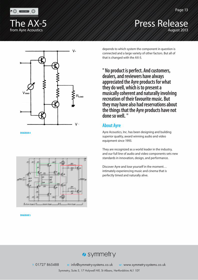
DIAGRAM 4
DIAGRAM 5
depends to which system the component in question is connected and a large variety of other factors. But all of that is changed with the AX-5.
" No product is perfect. And customers, dealers, and reviewers have always appreciated the Ayre products for what they do well, which is to present a musically coherent and naturally involving recreation of their favourite music. But they may have also had reservations about the things that the Ayre products have not done so well. "
About AyreAyre Acoustics, Inc. has been designing and building superior quality, award winning audio and video equipment since 1993.
They are recognized as a world leader in the industry, and our full line of audio and video components sets new standards in innovation, design, and performance.
Discover Ayre and lose yourself in the moment… intimately experiencing music and cinema that is perfectly timed and naturally alive.
t: 01727 865488 e: [email protected] w: www.symmetry-systems.co.uk
Symmetry, Suite 5, 17 Holywell Hill, St Albans, Hertfordshire AL1 1DT
t: 01727 865488 e: [email protected] w: www.symmetry-systems.co.uk
Symmetry, Suite 5, 17 Holywell Hill, St Albans, Hertfordshire AL1 1DT
The AX-5from Ayre Acoustics
Press ReleaseAugust 2013
Page 13
AX-5 Features- Ayre’s new Diamond output stage
- Ayre’s exclusive Equilock circuit
- Linear analog power supply
- Zero-feedback, fully-balanced discrete circuitry
- High-speed circuit board material
- Custom developed audio-grade resistors
- Ayre Conditioner power line RFI filter
- AyreLink communication system
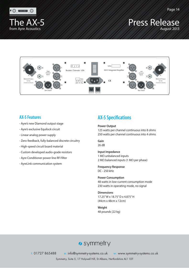
AX-5 SpecificationsPower Output 125 watts per channel continuous into 8 ohms 250 watts per channel continuous into 4 ohms
Gain 26 dB
Input Impedance 1 MΩ unbalanced inputs 2 MΩ balanced inputs (1 MΩ per phase)
Frequency Response DC - 250 kHz
Power Consumption 48 watts in low-current consumption mode 230 watts in operating mode, no signal
Dimensions 17.25” W x 18.75” D x 4.875” H (44cm x 48cm x 12cm)
Weight 48 pounds (22 kg)
t: 01727 865488 e: [email protected] w: www.symmetry-systems.co.uk
Symmetry, Suite 5, 17 Holywell Hill, St Albans, Hertfordshire AL1 1DT
The AX-5from Ayre Acoustics
Press ReleaseAugust 2013
Page 14