Embed Size (px)
Citation preview

II NRL Memorandum Report 2045
Corrosion Analysis of 304 Stainless Steel Wire Ropeand Fittings From a NOMAD Buoy Mooring System
0 . After 34-Months Continuous Servicein the Gulf of Mexico
T. J. LENNOX. JR.
Physical Metallurgy BranchAMetallurgy DiLisimi
September 1969
-'DDlC
j~Lc•, -•---- -',
NAVAL RESEARCH LABORATORY
Washington, D.C.
This documenl has bccn approved for public release and sale: its distribution is unlimited.

Contents
Abstract ...................................... iiStatus ......................................... iAuthorization ................................. ii
Introduction ........................................... 1
Procedures ............................................. 2
Corrosion Analysis and Discussion ...................... 2
Products on the Wire Rope Surfaces ................. 3.
Corrosion Observations and Data .................... 4
Wire Ropes ...................................... 4
Fitting Areas of Wire Rope and Fittings ........ 5
Wire Diameters ................................. 5
Summary ................................................. 6
Acknowledgment .......................................... 6
References ............................................. 7
f±

Abstract
Samples from a 1250-ft length of 304 stainless steel wirerope and associated stainless steel tube thimbles andstainless steel cable clamps were studied to determine theextent of corrosion after 34-months continuous immersioi" inthe Gulf of Mexico. This 3/4-in.-diam wire rope (6 x 19Warrington - IWRC 7 x 7) was used in the upper portion of aNomad buoy mooring system. The performance of this particularbuoy design is important because of its possible influence onthe national buoy program.
The absence of any significant corrosion on the top 1000 ftof this stainless steel wire rope was attributed to thebeneficial effects of the retained lubricant, to the cathodicprotection from a steel anode located just above the wire rope,and to probable inadvertent cathodic protection from the6061-T6 aluminum surface buoy.
The lower 250 ft of the wire rope was jacketed with neopreneto prevent abrasion of the synthetic rope used for the lowersection of the mooring system. The distance from the anodeand the electrical shielding effect of the jacket preventedeffective cathodic protection of this section of the rope, andrelatively severe corrosion was observed.
Experience gained in this stainless steel wire rope analysisand other wire rope corrosion analyses currently being conductedindicates that one cannot determine the extent of corrosion ofwire ropes by an inspection of only the exposed external surfaces.This is especially true when a material such as the common gradesof stainless steel is used because the corrosion of such materialoccurs locally by tunnelling or crevice corrosion or pitting and,therefore, may not be evident externally. For certain criticalapplications, i.e., where the system is not extremely over-designed, it may be necessary to replace the wire rope at thefirst sign of rope deterioration as evidenced by rusting orwhiskering.
Status
This report completes one phase of the task; work is continuingon other phases.
Authorization
NRL Problem No. 63M04-02Tasks SF 51-542-602-12431 and S-4607-11894
ii

INTRODUCTION
Because of the increased use of moorings to lower and secureinstrument packages and buoys in deep areas of the ocean,the Marine Corrosion Section of the Naval Research Laboratory'sMetallurgy Division has been concerned with the corrosionperformance of the various types of metallic wire ropes usedfor such moorings. An analysis of the failure of AUTEC TOTOII deep sea moor and of the performance of its cathodicprotection system was reported by Groover (1). The AUTECmoor was a three-legged moor and used 1 i/4-in.-diam 6 x 19filler wire (WSC), extra-improved plow steel, galvanized,bituminous-coated wire rope. A limited-size cathodic protectionsystem of magnesium anodes was designed by NRL and installed toprotect critical junctions of the moor. The service life ofthe TOTO II moor was approximately 4 1/2 years in 5000 ft ofseawater in the Tongue of the Ocean (TOTO) area of the BahamaIslands.
The Nomad buoy moor discussed in this report and located inthe Gulf of Mexico (lat 25-OON, long 90-00W) was recovered inApril 1969 after 34-months continuous service. This moor'wasunder the cognizance of the Naval Weapons Quality AssuranceOffice - Meteorological Instrumentation Division - QAO-56.The Nomad buoy has nominal dimensions of 20 x.10 x 8 ft,displaces approximately 10 tons, and has a loaded draft of7 ft. It was fabricated from 6061-T6 aluminum and was intendedto be isolated from the mooring with phenolic insulators.
The general design drawings for the Nomad buoy mooring systemshowed approximately 15 ft of 3/4-in. stainless steel chaindirectly beneath the buoy but isolated from it and approximately1000 ft of 3/4-in.-diam stainless steel wire rope below thechain. An iron anode was included in the moor design forcathodic protection purposes. The anode for this system waslocated near the top of the moor in the chain section. Theconstruction of the wire rope on the Nomad buoy moor studiedwas 6 x 19 Warrington (IWRC 7 x 7). The general design alsoshowed the lower end of the stainless steel wire rope to becovered by a 200-ft. length of fabric or rubber hose. Aneoprene jacket covered the lower 250 ft of the 304 stainlesssteel wire rope of the Nomad buoy moor discussed in this report.
A 7/8-in.-diam plaited dacron or polypropylene rope below thestainless steel wire rope was shown in the general Nomad buoymoor design. The fabric or rubber hose on the stainless steel
: 1

steel wire rope was specified to prevent chafing of thesynthetic rope by the stainless steel if at times the syntheticrope was not taut and rose toward the surface.
Previous studies (2,3) have shown very severe corrosion of 304stainless steel in seawater unless the specimens or structureswere receiving cathodic protection, hence the interest in abuoy which may influence the design of "standard" buoys andwhich afforded an opportunity to observe stainless steel wirerope after 34-months continuous immersion in seawater.
PROCEDURES
On 12 June 1969, NRL personnel visually inspected the approxi-mately 1250 ft of 304 stainless steel wire rope from the Nomadbuoy mooring system at the Washington Navy Yard. Specimens forthe corrosion study were selected from locations along the wirerope which the visual inspection indicated would be represen-tative of the wire rope's condition. The locations from whichthe specimens were removed for the corrosion study are shown inTable 1. Simultaneously, Mr. Norbert Rendler (NRL Code 8444)removed samples adjacent to the corrosion specimens in order tostudy the mechanical properties of the wire rope. The study onmechanical properties of this wire rope will be covered in aseparate report by Code 8444.
Products on the wire rope were removed from selected locationsfor spectrographic analysis and possible identification by x-raydiffraction. Approximately 3 to 4-in. lengths from each samplelocation were alternately delubricated with toluol in an ultra-sonic bath and chemically cleaned in 10 pezcent HNO3 at 60 0 Cprior to the microscopic examination. The microscopic studyincluded a detailed examination of many of the individual wires(usually all the wires in one outer strand and the IWRC of eachselected length). Cross sections of all the wire rope specimenswere prepared metallographically for study. Micrometer measure-ments were also obtained on the diameter of individual wires ofeach specimen.
CORROSION ANALYSIS AND DISCUSSION
The corrosion analysis of the stainless steel wire rope specimensand fittings bave been summarized in Tables 1 and 2, respectively.A description of the appearance of the wire rope at variousdistances from the top, corrosion observations on the cross-section specimens at 30X magnification, x-ray diffractionidentification of products on the wire rope surfaces at selectedlocations, observations on the overall appearance of individual
2
wires, and a qualitative simmary of the extent of corrosion
have been included in Table 1.
Products on the Wire Rope Surfaces
When a metal has been cathodically protected in seawater andcertain conditions of temperature and potential achieved, theprotected metal (the cathode) will have developed filius onits surface,. These films consist mainly of calcium andmagnesium salts and have been called calcareous deposits.In some areas of the ocean similar white deposits which areunrelated to the cathodic protection process may also beformed on metal surfaces. Such deposits have often beencalled "marl" and have resulted from marine-life decay.However, the origin of the deposit can be determined by x-raydiffraction techniques.
The visual inspection of the stainless steel wire rope showeda white product on its surfaces to a distance of slightly over100 ft from the top. X-ray diffraction analysis identifiedCaCO3 (calcite) as a major constituent of these products to adistance of 13 ft from the top, and calcite as a minor con-stituent to a distance of 104 1/2 ft. yFeO(OH) was alsoidentified in the products sampled at the 11 to 13-ft. distance.Microscopic examination of this section of wire rope showedessentially no corrosion (Fig. 1). The presence of ;-FeO(OH) atthis relatively short distance from the top of the wire ropewas believed to be the result of corrosion of the iron anodewhich was installed above this locati,-n for cathodic protectionpurposes. Spectrographic -lysis of the products on the wirerope at the 11 to 13-ft distance showed very strong lines forCa, Mg, Si. and strong lines for Al. The presence of aluminumand the CaCO3 (calcite) indicated that the wire rope was not onlybeing cathodically protected by the iron anode, but the aluminumbuoy probably was not isolated from the mooring for at least aportion of the exposure time. The aluminum hull buoy probablyfurnished additional cathodic protection to the wire rope.
Products on the stainless steel wire rope at the 1231 ft to1233-ft distance from the top were mainly rFeO(OH) and aFeO(OH).Spectrographic analysis of the products at this location gavestrong lines for Cr, Ni, and very strong lines for Fe. Thepresence of these elements and the iron compounds above wasconsistent with the corrosion of 304 stainless steel which wasa chromium-nickel-iron alloy. Strong lines for Ca and Mg werealso detected spectrographically on this specimen, but reasonsfor their presence were not known. Compounds that containedthese elements were not identifiable by x-ray diffraction which
3

I
* indicated either that their concentration was quite low orthat they were amorphous.
During cleaning of the wire rope sections for microscopicexamination, considerable lubricant was still evident betweenindividual wires. In order to adequately clean the specimensfor detailed examination it was necessary to alternatelyimmerse them in toluol in an ultrasonic bath and in 10 wt-percentHNO 3 at 60 0 C. A relatively large quantity of lubricant wasapparently retained in this stainless steel wire rope duringits 34-month exposure.
Corrosion Observations and Data
Wire Ropes -- Observations and data on the condition of the304 stainless steel wire rope moor of the Nomad buoy have beenassembled in Table 1 and Figs. 1 through 5. There was essentiallyno corrosion to a distance of approximately 520 ft from the topof the wire rope. The essential absence of corrosion has beenexemplified in Fig. 1 which is a typical photograph of thiscondition. The relatively excellent condition of the wire ropeto the 520-ft distance was attributed to the retained lubricantand to cathodic protection from the purposely installed ironanode and the apparently inadvertent cathodic protection fromthe aluminum buoy.
The outward visual appearance of the wire rope was similarbetween 520 ft and 1000 ft, and therefore no samples were takenin this span.
A definite transition was visually apparent between 1005 ftand 1009 ft. This transition was a change from a dark surfacefilm to a heavily rusted condition beneath the neoprene jacketwhich covered the bottom 250 ft (approximately) of the wirerope. Only slight corrosion was observed just above and 4 in.outside the neoprene jacket. The condition of the wire rope atthe rusted end of the transition area has been shown in Fig. 2.
As would be expected when 304 stainless steel was shielded andnot effectively cathodically protected, the corrosion under theneoprene jacket was quite severe. The tunnelling (black areasin cross-section photographs), deep pitting, and crevicecorrosion that occurred on individual wires located between1009 ft and 1233 ft from the top have been shown in Figs 3, 4,and 5. This tunnelling, deep pitting, and crevice corrosionwas typical for 304 stainless steel corrosion in quiescentseawater.
4

Fitting Areas of Wire Rope and Fittings -- The corrosionobserved on the wire rope under the 304 stainless steel cableclamps has been described in Table 1. The corrosion was muchmore severe on the shielded (with tape) areas at the lowerend of the wire rope compared to the areas near the top ofthe mooring which were unshielded and received cathodicprotection. A comparison of the extent of corrosion thatoccurred at these areas is indicated in Figs. 6 and 7. Thesevere pitting and crevice corrosion observed on the wire ropeunder one of the lower cable clamps are indicated in Fig. 8.
The overall condition of the upper and lower 304 stainlesssteel fittings, i.e., cable clamps, clamp nuts, and tubethimbles was generally excellent. Some shallow pitting hadoccurred, however, on the base metal of the tube thiinble inthe heat-affected zone caused by the welding of a wear plateto the tube thimble. A crack was also evident at the junctionof the weld and the tube thimble located at the top of thestainless steel wire rope. This crack may have been caused bya cold weld or by unaercutting during welding. The crackedarea before and after electrolytic etching in 10 percent oxalicacid is shown in Fig. 9.
Wire Diameters -- The individual wire diameters of thesample from the 11 ft to the 13-ft distance from the tope ofthe wire rope where essentially no corrosion was observed wereas follows:
Individual WireWire Location Diameters (mils)*
Outer StrandOuter Wires 41 and 54Inner Wires 54Center Wire 54
IWRCOuter Strand
Outer Wires 32Center Wire 32
Center StrandOuter Wires 35Center Wire 35
* m ril = 0.001 in.
5
L . ... _-

Diameters of wires from specimens taken at the variousdistances from the top of the wire rope were within plusor minus 1 mil of the values measured at the 11 ft to 13-ftdistance as shown above. These types of general corrosiondata were not unusual for stainless steel in seawater.Stainless steel generally has corroded locally by pittingor crevice corrosion in quiescent seawater. Generalcorrosion data have, therefore, not been found significantin determining the life expectancy of stainless steel hard-ware in seawater.
SUMMARY
The overall corrosion of the 304 stainless steel wire ropeof the Nomad buoy moor was :elatively minor considering its34-months service in seawater. The relatively good conditionof this wire rope can be attributed to the beneficial effectsof the retained lubricant, the cathodic protection from thesteel anode, and probable inadvertent cathodic protectionfrom the aluminum buuy.
Shielding of the lower eud of the stainless steel wire ropeto prevent chafing of the synthetic rope in the systemcaused the most serious corrosion to occur at these shieldedareas. The retained lubricant and any cathodic protectionthat might have been afforded the stainless steel wire ropeat the shielded areas were insufficient to prevent therelatively serious corrosion that was observed under theneoprene jacket.
Experience gained in this stainless steel wire rope analysisand other wire rope corrosion analyses currently being conductedindicates that one cannot determine the extent of corrosion ofwire ropes by an inspection of only the exposed external. surfaces.This is especially true when a material such as the common gradesof stainless steel is used because the corrosion of such materialoccurs locally by tunnelling or crevice corrosion or pitting and,therefore, may not be evident externally. For certain criticalapplications, i.e., where the system is not extremely over-designed, it may be necessary to replace the wire rope at thefirst sign of rope deterioration as evidenced by rusting orwhiskering.
ACKNOWLEDGMENT
Support of this research by the Naval Ships System Commandand the Deep Submergence Systems Project Office of theDepartment of the Navy is gratefully acknowledged.
6

REFERENCES
1. R. E. Groover, "Analysis of the Failure of AUTEC TOTO11 Deep Sea Moor and the Performance of Its CathodicProtection System," NRL Memorai!dum Report 1950,November 1968
2. M. H. Peterson and T. J. Lennoxf Jr., "'A"he CorrosionBehavior of Stainless Steels in Sea Water," NRLMemorandum Report 1795. June 1967
3. T. J. Lennox, Jr., M. H. Peterson, and R. E. Groover,"The Cz)rrosion Characteristics and Response to CathodicProtection of Several Stainless Steel Alloys in QuiescentSea Water; with a Partially Annotated Bibliography (SixthInterim Report of Progress)," NRL Menotandum Report 1948.November 1968
7

IIt~ RI
A1 Z 1*
cc 0 4; . . - '21.
-T I-1 I
00
a41 .. . ~ .k3 1t IsI b 0
CS 0-SV
>~ :2 N "a a1 'an-1 79 1.9 -- ,
.- 8. ___ ___ . ..
an 0C -a Hk
T=40 -1- 1.Y r1 a=..
-a - - 3
~~1- 1-I
A I- -0 2I:ý ,
10 Zi~ 7 * SI:1,' = 1A- - ~ ~1A

I >I0)
4 .0 QD
r 04-) 40
00 0r4 000 4) 0 H0)
~0 03 +.
000
0 car10- Pk 0
0z 0 2- V .04 $ 4 '0 4J
0 3Q : r 9)~ H $4)041 $4 0 0 Q) ccu Q 0
0 0O :: 0 $4 $4A.$4 3 0- C -4) 0 0a
40 v VV r-I v-)000. CH 4- tr V0 OH
(n 1$4b 0 0r s C n4 0 0 3~
O'f '4 4) $ C4 CHr.04l a 4) Dbl) ~ ~ 4 ;q .r :0 4k ý0 ) 43 . 0 Q) 0 H '00
04) *l >$ 4) C)0 aCM0 hD 4J'CDH tv a)0r4 9 0 4- 0 WOO- 0""q WD H0H00 c a 4J .) 4)C0 0o $0 ý: 0= v 00- 00
0 - 0 r4 0W (D :3$ '00r. $-4 4q 0 0 C : C, Q0 r4-
W 004 $4H 0r $4 rq'C ~4)0 w >~ $4 w
i-o $4- 04 Qr $4 0 ~ boz ic0 C:0 0 $ $4 0 k 4)r 0 r.r 0-
-Hr4 CH $44 00 IC) k -H +).U) >D N0 34 0 0p04 0 q
;4 esC 0 0r 0 Q~ Q C4 0r
$4~P 0 0 0)ca En 00 *r4' r- '4 -H $4 N l4)4P,) CD0 > co 00i > -w 20 Z 4)4 00 0l 0 b ' ca40v
V 0 S4~ $4 $4a p 4))) =CDH ca 00 0 3Q04 90. (D 1) 0H 0)~ 0).0
VCf 0*- 0$4 0n C-$ C0 k 00 W~ 0 P 0'0 0 C0w r-4' M4 H0 Mp 0~j
-H 4. H >$4 CD H
U ) 0 04) C
CO4) ce 020 0 ~ 4 ~ Op
0$u HH r-4 0 .0
00 z0 ;.O 4 kO C O. CO
0'4 (D 4 ) 4 - )Q
00 i r- H:
.E-

I C
MC247
(a) Cross section (5X rmagnification)
(b) I-WRC, center strand, outer wire(15X magniflication)
Fig. 1 - 304 stainless steel wire rope alter 34-monthscontinuous immersion as part of a -Nomiad buoy moor-ing system, showing the essential absence of c o rro -
s ion at a distance of 11-13 ft from the top of the wire
rope.
10

(el Cross section (5X magnification)
(b) Outer strand, inner wire115X magnification"
(c.) IWRC, center strand, outer wire(15X magnification)
Fig, 2 - 304 stainless steel wire rope after 34-monthscontinuous immersion as part of a Nomad buoy moor-ing system, showing the moderate-io-serve corrosional. a distance of 1006 ft-7 in. to I ýJ8 ft-7 in. f ro r thetop of the wire rope (rusted end of transittion - underneoprene jacket).
(a) Cross section (5X magnification)
(b) Outer strand, inner wire(15X magnification)
(c) ThVRC, center strand, outer wire(15X magnification)
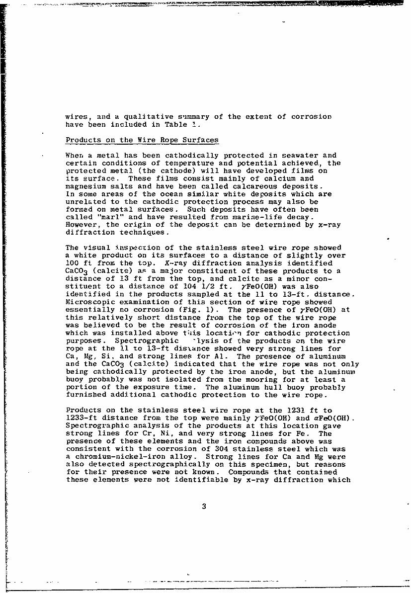
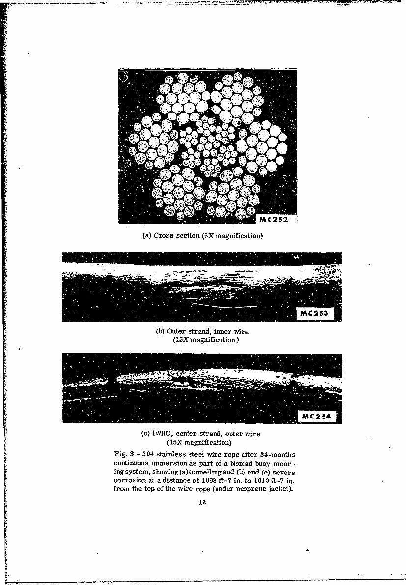
Fig. 3 - 304- stainless steel wire rope after 34-monthscontinuous immersion as part of a Nomad buoy moor-ing system, show~ing (a) tunnelling and (b) and (c) severecorrosion at a distance of 1008 ft-7 in. to 1010 ft-7 in.from the top of the wire rope (under neoprene jacket).
12

(a) Cross section (5X magnification)
(b) Outer strand, large outer wire(15X magnification)
(c) BVRC, center strand, outer wire(15X magnification)
Fig. 4 - 304 stainless steel Vire rope after 34-months continuousimmersion as part of a Nomad buoy mooring system, showing (a)limited tunnelling, but (b) and (c) deep pitting on individual -wiresat a distance of 1089 ft-8 in. to 1090 ft'-8 in. from the top of thewire rope (bright appearance under jacket).
13
(a) Cross section (5X magnification)
(b) Outer strand, outer small wire(15X magnification)
(c) MIRC, center strand, outer wire(15X magnification)
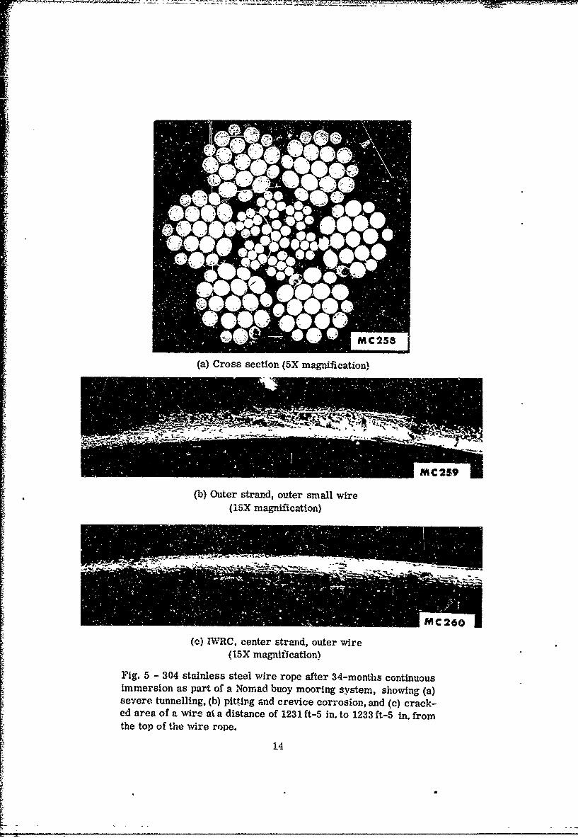
Fig. 5 - 304 stainless steel wire rope after 34-months continuousimmersion as part of a Nomad buoy mooring system, showing (a)severe tunnelling, (b) pitt~ing and crevice corrosion, and (c) crack-ed area of a wire at a distance of 1231 ft-s in. to 1233 ft-5 in. fromthe top of the wire rope.
14
K•

Fig. 6 - 304 stainless steel wire rope after 34-monthocontinuous immersion as part of a Nomad buoy moor-ing system, showing the good c on d it ion of the wirerope under a cable clamp at the top of the wire rope(5X magnification).
MC 262
Fig. 7 - 304 stainless steel wire rope after 34-monthscontinuous immersion as part of a Nomad buoy moor-ing system, showing corrosion at periphery o f s o m ewires under a cable clamp near the bottom of the wirerope (clamp and wire rope shielded with tape) (5 mag -nification).
15

Fig. 8 - 304 stainless stee! wire rope after 34-monthscontinuous Immersion as pazt of a Nomad buoy moor-ing system, showving severe pitting anid crevice corro-sion under a cable clamp near thie bottom of the wirerope (clamip and wire rope were shielded -with tape)(15X magnification).
16

II /
(Page 18 is Blank)
7 -.
(a) Unetched (IOOX magnification)
(b) Electrolytic etch - 10% oxalic acid(IOOX magnification)
Fig. 9 - Section of 304 stainless steel wire rope tube thimbleshowing crack which may have been caused by a cold weld orby undercutting during welding.
17

UNCLASSIFIED
Security Classification
DOCUMENT CONTROL DATA. R&D(Security €et4aaaicgtlo.,I 0of title bod) of abstract and indexinS annotation must be entered w"en the OVereli repo:t is clasifiled)
I OqIGINATING ACTIVI'.V (Corporate author) e2a REPORT SECURITY C LASSIFICATION
Naval Research Laboratory UnclassifiedWashington, D.C. 20390 2b GROUP
3- REPONT TITLE
Corrosion Analysis of 3'J4 Stainless Steel Wire Rope and Fittingsfrom a Nomad Buoy Mooring System After 34-Months Continuous Servicein the Gulf of Mexico
4. DESCRIPTIVE NOTFS (T"pe of report and inclualve date¢)
Progress ReportS. AUTHOR(S) (Leet none. first name, Initial)
Lennox, Thomas J., Jr.
6. REPORT DATE 7a TOTAL NO. OF PAGES r 7b. NO. OF REFS
September 1969 22 38411 CONTRACT OR ORAPJY NO. a& ORIGINATOR'S REPORT NUMBER(S)
NRL Problem-M04-02b. PRo-jCTNO. SF 51-542-602-12431- NRL Memorandum Report 2045
S-4607-11894C.96. 0TH~l ER. ftPO4tT NO(S) (A -i other number* that may be acalInod
this report)
d.
10. A VA h. ABIL.ITY/LIM;TATION NOTICES
This document has been approved for public release and sale; its distribution is Unlimited.
11- SUPPLEMENTARY NOTES 112. SPONSORING MILITARY ACTIVSTY
Naval Ship Systems Command andDeep Submergence Systems ProjectOffice, Department of Navy
13. ABSTRACT
Samples from a 1250-ft length of 304 stainless steel wire ropeand associated stainless steel tube thimbles and stainless steelcable clamps were studied to determine the extent of corrosion after34-months continuous .mmersion in the Gulf of Mexico. This 3/4-in.-diam wire rope (6 x 19 Warrington - IWRC 7 x 7) was used in theupper portion of a Nomad buoy mooring system. The performance ofthis particular buoy design is important because of its possibleinfluence on the national buoy program.
The absence of any significai.t corrosion on the top 1000 ft ofthis stainless steel wire rope_ was attributed to the beneficialeffects of the retained lubricant, to the cathodic protection from asteel anode located just above the wire rope, and to probable iliad-vertent cathodic protection from the 6061-T6 aluminum surface buoy.
The lower 250 ft of the wire rope was jacketed with neoprene toprevent abrasion of the synthetic rope used for the lower section ofthe mooring system. The distance from the anode and the electricalshielding effect of the jacket prevented effective cathodic protectionof this section of the rope, and relatively severe corrosion wasobserved.
Experience gained in this stainless steel wire rope analysis andother wire rope corrosion analyses currently being conducted indi-
cates that one cannot determine the extent of corrosion of wire ropes
(Scontd)DD 1473 UNCLASSIF DSecurity Classification
'A-

IA.CLAFSqIFIFDSvcui'ity Cu, ,~ication
14~~ LIN A LIKIt- IKEY WORDS---
ROLE WY ROLL WYZ tO L~ 9 WT
Cathodic ProtectionFittings
Marine CorrosionNomad Buoy Mooring System
Stainless Steel
Wire Rope
by an inspection of only the exposed external surfaces. This isespecially true when a material such as the common grades ofstainless steel is used because the corrosion of such i-aterialoccurs locally by tunnelling or crevice corrosion or pittingand, therefore, may not be evident externally. For certaincritical applications, i.e., where the system is not extremelyover-designed, it may be necessary to replace the wire ropeat the first sign of rope deterioration as evidenced by rusting
or hseig
NO,14V 4547 20 UNCLASSIFIED(P AGE 2) Security Class~ifiation