Embed Size (px)
Citation preview
Separating Texture and Illumination forSingle-Shot Structured Light Reconstruction
Minh [email protected]
Srinivasa G. [email protected]
Robotics Institute, Carnegie Mellon University, USA
Yaser [email protected]
Abstract
Active illumination based methods have a trade-off be-tween acquisition time and resolution of the estimated 3Dshapes. Multi-shot approaches can generate dense recon-structions but require stationary scenes. In contrast, single-shot methods are applicable to dynamic objects but can onlyestimate sparse reconstructions and are sensitive to surfacetexture. In this work, we develop a single-shot approachto produce dense reconstructions of highly textured objects.The key to our approach is an image decomposition schemethat can recover the illumination and the texture imagesfrom their mixed appearance. Despite the complex appear-ances of the illuminated textured regions, our method canaccurately compute per pixel warps from the illuminationpattern and the texture template to the observed image. Thetexture template is obtained by interleaving the projectionsequence with an all-white pattern. Our estimated warpingfunctions are reliable even with infrequent interleaved pro-jection. Thus, we obtain detailed shape reconstruction anddense motion tracking of the textured surfaces. We validatethe approach on synthetic and real data containing subtlenon-rigid surface deformations.
1. IntroductionStructured light based shape reconstruction algorithms
are divided into two categories: multi-shot [4, 6, 15] andsingle-shot methods [7, 14, 17]. Multi-shot methods can es-timate per-pixel depth map for a wide range of objects usingtemporal coding of the illumination patterns but require thescene to be stationary during image acquisition. Single-shotmethods can work for dynamic objects by decoding the spa-tial structure embedded in the illumination pattern but gen-erate low spatial resolution reconstructions and are suscep-tible to the high frequency texture on the object surface (seeFigure 1 for examples).
In this work, we present a single-shot structured light
http://www.cs.cmu.edu/∼ILIM/projects/IL/TextIllumSep
Figure 1. Conventional single-shot structured light systems oftenfail for highly textured objects. The mixture of albedo variationsand high frequency illumination patterns makes it difficult to es-tablish reliable and dense camera-projector correspondences.
system that can estimate high spatial and temporal resolu-tion depth even for highly textured objects. The proposedmethod is single-shot in the sense that it does not use theilluminated images in the previous frames to temporally de-code the illumination pattern. Our system consists of onecamera and one projector. The projector generates high fre-quency illumination patterns needed to estimate dense 3Dshape. We decompose the observed mixed appearance im-ages into the surface texture and the projected illuminationpattern. Because of this decomposition, high resolution 3Dshape of the object in the textured regions can be reliablyestimated. In addition, we obtain dense tracking inside thetexture region in the presence of the illumination pattern.
To achieve the illumination-texture separation, we de-velop an optimization framework that estimates warps ofboth the illumination pattern and a reference texture tem-plate to compose the observed image. The texture templateis obtained by infrequently interleaving the projection se-quence with an all-white pattern. The warping functionsare computed starting from a sparse set of correspondencesbetween the camera and the projector. The results are greed-ily propagated into textured areas where spatial correspon-dences cannot be directly estimated. Figure 1 shows severaltypes of surface texture that our method can handle.
Since the method computes warps to a template, it doesnot exhibit drift over time. Moreover, unlike conventionalsingle-shot structured light systems whose performancesdegrade as surface texture frequency increases, our method
1

achieves better decomposition accuracy with higher fre-quency texture. Finally, despite being presented for single-shot approaches, this method can also be used in conjunc-tion with multi-shot systems by spatially modulating the il-lumination patterns with a random pattern [18]. We demon-strate dense and accurate decomposition and reconstructionresults on both synthetic and real data with non-rigidly de-forming objects.
2. Related WorkActive illumination has been used to estimate shape es-
timation problem with major focus on designing coded pat-terns that are robust to occlusion, depth discontinuity, andalbedo variations [11]. A conventional structured light sys-tem has to choose appropriate illumination patterns depend-ing on its temporal or spatial resolution requirements. Sincemulti-shot methods can robustly generate high spatial reso-lution but require stationary scenes, motion compensationschemes have been developed to handle slowly moving ob-jects [16]. Another common approach is to interleave thepatterns for structure estimation with patterns optimized forcomputing motion [8].
On the other hand, single-shot methods sacrifice spa-tial resolution for high temporal resolution reconstruction.However, because of the spatial coding strategy, generallythese methods cannot deal with textured objects and theyare forced to rely on specific light patterns for differenttypes of surface texture. Koninckx et al. [9] mitigate theproblem by introducing a feedback loop that changes pat-terns according to the error in the decoding process. Yet,they rely on heuristic rules to set the color codes depend-ing on different textured surfaces. In principle, this methodtreats the surface texture as a nuisance and designs illumina-tion patterns robust to the texture. Conversely, our methodconsiders the texture as an additional source of informationthat needs to be recovered along with the 3D shapes. Tothe best of our knowledge, this is the first work to explicitlyseparate high frequency texture and illumination patterns inthe context of structured light system.
Another solution for single-shot methods to handle ob-ject with both textured and textureless regions is to employmulti-view stereo systems. These systems treat the illumi-nation pattern as surface texture to assist the matching [19].However, since this method requires at least two cameras inaddition to a projector in between, baseline between cam-eras is larger which makes correspondence estimation hard.
Our image decomposition method is similar in spiritto intrinsic image estimation [5, 12]. These works makesmoothness assumptions about the environment light (thesun, the sky, or indoor lights) and estimate the reflectanceand shading images from images captured by a single cam-era. Conversely, our work decomposes the high frequencyillumination patterns and texture from the observed mixed
appearance image. Additionally, our method is specificallydesigned for single-shot structured light systems that con-sist of one camera and one projector.
3. Texture-Illumination DecompositionConsider an object being illuminated by a projector.
Similar to intrinsic image estimation, the brightness I(x, y)at location (x, y) in the observed image is modeled as a mul-tiplication of a texture image IT (x, y) and the illuminationimage IL(x, y) at that location:
I(x, y) = IT (x, y)IL(x, y). (1)
The texture image IT is the image observed if the pro-jector illuminates an all-white pattern on the object. Theillumination image IL is the incident lighting pattern. Equa-tion 1 is ill-posed because it has two unknowns IT (x, y) andIL(x, y) in one equation. To handle this under-constrainedproblem, we require additional knowledge of the referencetemplates for the illumination and texture source and aproper per-pixel initialization of the unknowns. Since theillumination image is a projection of the known projectorpattern, this pattern serves as one of our references. The ref-erence texture template can be obtained by interleaving theprojection sequence with a white pattern. The initializationproblem is solved by the greedy correspondence growingalgorithm [3]. We describe the method in detail below.
3.1. Mathematical Formulation of the Objective
Figure 2 shows a sequence of images of an object beingilluminated by the projector. Initially, the projector illumi-nates the scene with an all-white pattern so that the texturetemplate T is observed. The appearance of this template ITchanges according to the movement of the object. Becauseimage deformation is high-dimensional and non-linear, an-alytic forms that describe consistent deformation behaviorover the entire image do not exist. Thus, we locally modelthis distortion by a warping function f and employ con-stant gain aT and offset bT to approximate for the intensitychanges between the two images due to changes in surfacenormals, light directions and ambient illumination:
IT (x, y) = aTT (f(x, y)) + bT , (2)
where f(x, y) maps the coordinate of point (x, y) in theobserved image to its corresponding location in the texturetemplate T . Similarly, the illumination image IL is the pro-jection of light pattern L on the object and hence, is relatedto each other by a set of local warping functions g. We as-sume the projector has been photometrically calibrated andadopt a linear model to relate the brightness of the pure il-lumination image to the projecting pattern:
IL(x, y) = aLL(g(x, y)) + bL, (3)

IL1
T IT2
L IL2
I1
IT1
I2
compose
g2
g1
compose
compose
compose
Time 1 Time 2 Time 0
I 11
g2
IIL1L1gg1
f2
f1
initialize
Figure 2. Texture and illumination image decomposition. Thegreen texture region in the template T is warped to the pure textureimage ITi by the function fi. The red squares from the illumina-tion pattern L are mapped to the pure illumination image ILi bythe function gi. Properly composing the illuminated red squaresin ILi with the green region in ITi turns them into yellow squares,which constitute the mixture image Ii observed at time i. Noticethat spatially adjacent squares are likely to have similar warpingparameters. By using the estimated warping parameters of the pre-vious frame to initialize warps between the observed frame to itsreference templates L and T , the warping function can be reliablyestimated even with infrequent interleaving.
where g(x, y) relates the point (x, y) to its matches in theillumination image L and aL, bL are constant gain and off-set to compensate for the brightness difference between theprojector pattern and the observed illumination.
To increase the robustness of the warping functions tolarge deformation, we set them to be locally affine and min-imize the following cost function for their shape parametersand the photometric compensation coefficients:
N∑k=−N
N∑l=−N
[IT (xk, yl)IL(xk, yl)− I(xk, yl)]2, (4)
over a patch of size (2N + 1) × (2N + 1) centered atpoint (x0, y0), where we want to decompose. These warp-ing functions are given as:
f(xk, yl) =
[x0 + p0 + (p2 + 1)k + p3ly0 + p1 + p4k + (p5 + 1)l
],
g(xk, yl) =
[x0 + q0dx + (q1 + 1)k + q2ly0 + q0dy + q3k + (q4 + 1)l
],
(5)
where (dx, dy) is the normalized vector representing thedirection of the epipolar line in the projector image, and
q0..4, p0..5 are the affine warp parameters. Similar to stereomatching, we simplify the parameterization of g by con-straining it to lie on the camera-projector epipolar line.Equation 4 is optimized at every patch in the textured re-gions using the Gauss-Newton method.
3.2. Pixel-wise Initialization
Due to perspective distortion in the illumination imageIL and the large deviation from the texture template T forfast moving objects, good initial guesses for the warping pa-rameters are required to optimize equation 4. Even with ran-dom patterns [4], the repetitive nature of the spatial neigh-bor coding illumination pattern exacerbates the local mini-mum problem. We solve the initialization problem as fol-lows: start from the texture boundary regions and greedilypropagate the results to the interior texture area. We employthe three steps to initialize points at the boundary.Step 1: Compute dense matching between camera and pro-jector using a greedy correspondence growing algorithm[3]. This greedy growing strategy and the use of a randomillumination pattern allows us to establish dense correspon-dences everywhere except for the textured surface regions.Here, the texture boundary is naturally defined as placeswhere spatial correspondences are not obtainable.Step 2: For a pixel that is close to the textured region bound-ary, we exhaustively search in its local neighbor for patcheson the illumination pattern and texture template that min-imizes the cost defined in Equation 4. Depending on themotion of the objects, the search range of pixels close to thetexture boundary is set a priory. Because of the deformationbetween patches in the templates and the ones in the puretexture and illumination images, patches in the templatesare pre-warped before being used to examine their contri-bution to the cost function. The warping parameters of theillumination pattern are initialized from its spatial neighborcomputed in step 1. Those of the texture templates are setto either its temporal neighbor if available or to the zero de-formation state.Step 3: Refine the best locations of the illumination andtexture patches by optimizing the cost function in Equation4 using a standard Gauss-Newton method.
Owing to the use of the texture warping parameters es-timated in the previous frame as initialization, our warpingfunctions can robustly warp observed patch to its referencetemplate that is temporally far away. Hence, only infrequentprojection of the interleaving white frame is needed and theobtained results have high temporal resolution. This strat-egy is analogous to the approach of Tian and Narasimhan etal. [13] who use less distorted patches to estimate globallyoptimal sets of warping parameters.
In spite of the greedy correspondence growing strategy,erroneous guesses can not propagate long as examined andthresholded by the cost function in Equation 4. Hence, our
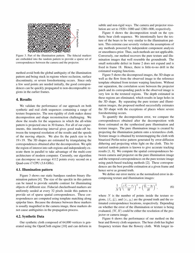
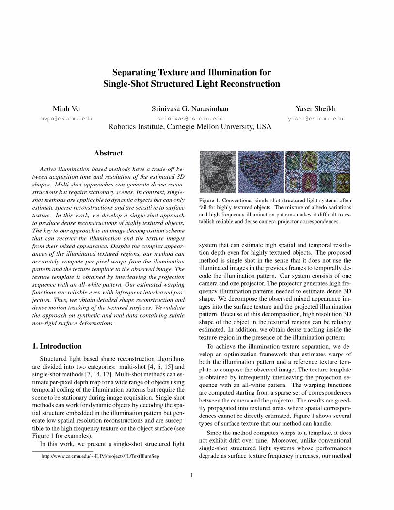
Figure 3. Part of the illumination pattern. The fiducial markersare embedded into the random pattern to provide a sparse set ofcorrespondences between the camera and the projector.
method avoid both the global ambiguity of the illuminationpattern and being stuck in regions where occlusion, surfacediscontinuity, or severe foreshortening occurs. Since onlya few seed points are needed initially, the good correspon-dences can be quickly propagated to non-decomposable re-gions in the earlier frames.
4. ResultsWe validate the performance of our approach on both
synthetic and real cloth sequences containing a range oftexture frequencies. The non-rigidity of cloth makes densedecomposition and shape reconstruction challenging. Weshow the results for the sequences in which the all-whitepattern is projected once in 30 frames. For all of our exper-iments, this interleaving interval gives good trade-off be-tween the temporal resolution of the results and the speedsof the moving objects. We also fix the patch size to be19×19. The 3D shapes are estimated by triangulating thecorrespondences obtained after the decomposition. We splitthe region of interest into sub-regions and independently ex-ecute them in parallel to take advantage of the multi-corearchitecture of modern computer. Currently, our algorithmcan decompose on average 4112 points every second on aQuad-core i7 CPU (3.6 GHz).
4.1. Illumination pattern
Figure 3 shows our static bandpass random binary illu-mination pattern [4]. The size of the speckle in this patterncan be tuned to provide suitable contrast for illuminatingobjects of different size. Fiducial checkerboard markers areuniformly seeded at every 32 pixels inside this pattern toprovide set of sparse spatial correspondences. These cor-respondences are computed using template matching alongepipolar lines. Because the distance between these markersis usually magnified in the camera image, these markers donot cause ambiguities in the propagation process.
4.2. Synthetic Data
Our synthetic cloth composed of 64,000 vertices is gen-erated using the OpenCloth engine [10] and can deform in
subtle and non-rigid ways. The camera and projector reso-lution are set to 1920×1080 and 1280×800, respectively.
Figure 4 shows the decomposition result on the syn-thetic bear cloth sequence. We intentionally have the tex-ture of the bears to be very similar to the illumination pat-tern. This extreme case severely violates the assumptions ofany methods powered by independent component analysisor smoothness prior. Thus, such methods are not applicable.Conversely, our method recovers the pure texture and illu-mination images that well resemble the groundtruth. Thesmall noticeable defect in frame 2 does not expand and isfixed in frame 18. Hence, there is little-to-no drift in theestimated warping functions.
Figure 5 shows the decomposed images, the 3D shape aswell as the flow from the observed image to the referencetemplate obtained from texture warping functions. Withoutour separation, the correlation score between the projectorpatch and its corresponding patch in the observed image isvery low in the textured regions. The depth estimated inthese regions are eliminated, which results in large holes inthe 3D shape. By separating the pure texture and illumi-nation images, the proposed method successfully estimatesthe 3D shape with the exceptions of places where severeforeshortening occurs.
To quantify the decomposition error, we compare thecorrespondences obtained after the decomposition withthose estimated on the synthesized pure illumination andtexture images. The pure illumination image is created byprojecting the illumination pattern onto a textureless cloth.Texture image is obtained by texturemapping the cloth withbinarized Perlin-noise pattern generated by error-diffusiondithering and projecting white light on the cloth. This bi-narized random pattern is known to give accurate trackingresults [1, 8]. We compute the spatial correspondences be-tween camera and projector on the pure illumination imageand the temporal correspondences on the pure texture imageusing patch-based tracking methods [2]. These correspon-dences are the best possible estimation at a given frame andhence serve as ground truth.
We define our error metric as the normalized error in de-composing texture and illumination images:
1
N
√( xi − xi
W
)2+( yi − yi
H
)2, (6)
where N is the number of points inside the texture re-gions, (xi, yi), and (xi, yi) are the ground truth and the es-timated correspondence locations, respectively. Dependingon whether the error of the illumination or texture is beingevaluated, (W,H) could be either the resolution of the pro-jector or camera image.
Figure 6 shows the performance of our method on thebear and flowery cloth sequences. The bear cloth has higherfrequency texture than the flowery cloth. With longer in-
Decomposed illumination at frame 18
Ground truth illumination at frame 18
Observed image and its magnified mixed
appearance region at frame 18
Ground truth illumination at frame 2 Ground truth texture at frame 18 Ground truth texture at frame 2
Decomposed illumination at frame 2 Decomposed texture at frame 18 Decomposed texture at frame 2
Observed image and its magnified mixed
appearance region at frame 2
Figure 4. Decomposition of the texture and illumination images of the synthetic bear cloth sequences. The interleaving pattern is projectedevery 30 frames. The same region of the bear in the two images is magnified to show how its intricate appearance changes over time whenit is illuminated by the projector. Because of cloth folding, bear appears smaller in the vertical direction. Visually, the illumination imagesexperiences higher deformation than the texture images. The noticeable defect in the decomposition at frame 2 has been fixed in frame 18.
terleaving sequences, larger deformation in the image de-grades the algorithm performance. Yet, no explosion in thedecomposed texture and illumination error is observed. Thetexture decomposition error and the fraction of correspon-dences estimated for flowery sequence are not as good asfor the bear sequence. This indicates that the algorithm per-forms better with higher frequency texture. The explanationfor this phenomenon is similar to the optical flow problem:tracking highly textured surfaces suffers from less drift. No-tice that because of the coherent structure of the bear, thealgorithm fails when the entire texture boundary cannot beestimated reliably. This results in the abrupt drop in thefraction of estimated correspondences. Nevertheless, ini-tially, the accuracy of decomposing the illumination for theflowery cloth sequence is competitive to the bear sequence
until influence of the decomposed texture error overwhelmsthe overall result.
4.3. Real Data
We conduct several real experiments with different clothdeformation and different texture frequencies. For all of ourexperiments, the scenes are illuminated using a 1280×800DLP View Sonic projector and the images are acquired bythe Canon XH-G1s HD 1920×1080 camera operating at30fps. The camera and projector are calibrated using themethod of Vo et al [15]. As in the synthetic dataset, weproject an all-white frame every 30 frames. The results arepresented without any post-processing.
Figure 7 shows our results on the dogs and flag se-quences. Despite the simple image formation model, our

3D shape computed
with texture decomposition
Observed image Decomposed texture Reference template
Estimating depth error with
respect to the ground truth
Depth map computed with
texture decomposition
Depth map computed without
texture decomposition
Texture flow
Figure 5. Decomposition of the texture and illumination images from a synthetic flowery cloth sequence with interleaving pattern projectedevery 30 frames. The depth map estimated after removing the texture not only shows its completeness over depth map obtained withouttexture removal but its high accuracy with respect to ground truth depth. The displacement of the texture regions with respect to thereference template is also estimated from the decomposition results.
(b)
(d) (c)
(a)
Figure 6. The accuracy and robustness of the decomposition withrespect to the interleaving period. (a) The median distance fromthe current frame to the reference template and the accumula-tive median displacement over frames (b) Percentage of camera-projector correspondences obtained in the textured regions (c)Normalized illumination error (d) Normalized texture error. Theerror is evaluated only for points inside the textured regions and iscomputed by Equation 6.
approach can handle complex appearances of real worldtextured objects illuminated by the projector. We believethis is due to the local block decomposition strategy whichis robust to global lighting variation. As shown in the flagsequence, while the texture decomposition could be incom-plete, especially for low frequency textured objects, thequality of the decomposed illumination is less affected bythe texture frequency. Due to the relatively large size of the
Kinect RGB 3D shape
Figure 8. 3D shape from the Kinect. Note that smoothing filtershas been applied to generate the mesh from raw point cloud data.
textured region, the 3D shape of this folding cloth cannotbe obtained by hole-filling or interpolation algorithms. De-spite the mixed appearance, the texture flow estimated withrespect to the reference template is also obtained.
Figure 8 shows the 3D shape obtained from the Kinectsensor. For fair comparison with the performance of theproposed method shown in the T-shirt sequence (see Fig-ure 7), the same subject is standing at a similar distance tothe sensor. Visually, the quality 3D shape from our methodoutperforms that of the Kinect. It is noteworthy that unlesssmoothing filter is applied to raw Kinect results, the meshgeneration fails as the surface normal computed from rawpoint cloud is noisy.
4.4. Texture Flow vs. Illumination Flow
Besides the motion of the textured regions, there is alsoan apparent motion due to the illumination pattern. As il-lustrated in Figure 9, the flow direction of the illuminationpattern and the texture are remarkably different from eachother. Unlike the motion flow which presents the movementof points on the object surface, the observed illumination isthe projection of the ray emanating from the light sourceand hence, its flow field must move only on the epipo-

3D shape obtained with
texture decomposition : view 2
Observed image Decomposed texture Texture flow
3D shape obtained without
texture separation
3D shape obtained with
texture decomposition: view 1
3D shape obtained with
texture decomposition : view 2
Observed image Decomposed texture Texture flow
3D shape obtained without
texture separation
3D shape obtained with
texture decomposition: view 1
Figure 7. Decomposition of the texture and illumination images from real cloth sequences. The interleaving pattern is projected every 30frames. After the decomposing process, the 3D shape can be obtained in the textured regions. No post-processing is applied. Applyinghole-filling methods on the 3D shape estimated without texture decomposing cannot yield appealing results because of the relatively largetextured regions. Despite the mixed appearance, the texture flow faithfully shows how the cloth is moving.
lar line of the camera-projector system. Furthermore, thisflow field encodes the changes in depths of rays emanatingfrom the light source that hit the object. Because establish-ing spatial correspondences between camera and projectoris much more difficult than estimating temporal correspon-dences, especially in the wide baseline scenario, any struc-
tured light system can gain benefit from the temporal co-herency of the illumination flow. Future work will inves-tigate different approaches to incorporate illumination flowconstraint into structured light reconstruction algorithms.

Illumination flow Illumination flow Texture flow Texture flow
Figure 9. Observed motion flow and illumination flow when a moving textured object is illuminated by point light source. While thedirections of texture flow follow the movement of the object, the directions of the illumination flow are constrained to be on the camera-projector epipolar line. The figure is best viewed in the electronic version.
5. Discussion
While we only show the results for a single deformingobject, our algorithm is applicable to general scenes con-taining multiple objects. As long as the seed points, i.e.correspondences established in low frequency textured re-gions, are available on the object, these correspondencescan propagate to the entire object. Nevertheless, becauseof the nature of the patch decomposition approach, our al-gorithm cannot handle well the textured regions at the oc-cluding boundary.
For objects with completely high frequency texture, theproposed algorithm will fail. Yet, such cases are rare andmost objects have a mixture of low and high frequencytexture regions (see Figure 5). While our approach mayalso fail for objects with low frequency texture, the camera-projector correspondence can be established to reconstruct3D shape. Moreoever, these correspondences can also beexploited to separate the texture out of the observed image.
Since the interleaving sequence is dependent on the mo-tion of the object, the interleaving period has to be adaptedto different applications. Nevertheless, in an era 60-fps con-sumer grade camera, there is no need to interleave everyframe, especially for daily human activity.
Acknowledgement: This research was supported inparts by an ONR Grant N00014-11-1-0295, a NSF GrantIIS-1317749, and a NSF Grant No. 1353120.
References[1] B. Atcheson, W. Heidrich, and I. Ihrke. An evaluation of
optical flow algorithms for background oriented schlierenimaging. Experiments in fluids, 2009.
[2] S. Baker and I. Matthews. Lucas-kanade 20 years on: Aunifying framework. IJCV, 2004.
[3] J. Cech, J. Sanchez-Riera, and R. Horaud. Scene flow esti-mation by growing correspondence seeds. In CVPR, 2011.
[4] V. Couture, N. Martin, and S. Roy. Unstructured light scan-ning to overcome interreflections. In ICCV, 2011.
[5] G. D. Finlayson, S. D. Hordley, C. Lu, and M. S. Drew. Onthe removal of shadows from images. PAMI, 2006.
[6] M. Gupta and S. K. Nayar. Micro phase shifting. In CVPR,2012.
[7] H. Kawasaki, R. Furukawa, R. Sagawa, and Y. Yagi. Dy-namic scene shape reconstruction using a single structuredlight pattern. In CVPR, 2008.
[8] S. Konig and S. Gumhold. Image-based motion compensa-tion for structured light scanning of dynamic surfaces. In-ternational Journal of Intelligent Systems Technologies andApplications, 2008.
[9] T. P. Koninckx, A. Griesser, and L. Van Gool. Real-timerange scanning of deformable surfaces by adaptively codedstructured light. In 3DIM, 2003.
[10] M. Movania. Openclothhttps://code.google.com/p/opencloth/, 2011.
[11] J. Salvi, S. Fernandez, T. Pribanic, and X. Llado. A state ofthe art in structured light patterns for surface profilometry.Pattern recognition, 2010.
[12] M. F. Tappen, W. T. Freeman, and E. H. Adelson. Recoveringintrinsic images from a single image. PAMI, 2005.
[13] Y. Tian and S. G. Narasimhan. Globally optimal estimationof nonrigid image distortion. IJCV, 2012.
[14] A. O. Ulusoy, F. Calakli, and G. Taubin. One-shot scanningusing de bruijn spaced grids. In ICCV Workshops, 2009.
[15] M. Vo, Z. Wang, B. Pan, and T. Pan. Hyper-accurate flex-ible calibration technique for fringe-projection-based three-dimensional imaging. OpEx, 2012.
[16] T. Weise, B. Leibe, and L. Van Gool. Fast 3d scanning withautomatic motion compensation. In CVPR, 2007.
[17] S. Yamazaki, A. Nukada, and M. Mochimaru. Hammingcolor code for dense and robust one-shot 3d scanning. InBMVC, 2011.
[18] Z. Yang, Z. Xiong, Y. Zhang, J. Wang, and F. Wu. Depth ac-quisition from density modulated binary patterns. In CVPR,2013.
[19] L. Zhang, B. Curless, and S. M. Seitz. Spacetime stereo:Shape recovery for dynamic scenes. In CVPR, 2003.