Embed Size (px)
Citation preview
SEPA CF CELLASSEMBLY & OPERATION
MANUAL

1. INTRODUCTION ........................................................................................ 1
2. SEPA CF CELL COMPONENTS ............................................................ 2
3. SEPA CF CELL ASSEMBLY ......................................................................4
4. OPERATION OF THE SEPA CF CELL .................................................. 11
5. SUPPLEMENTARY OPERATING INFORMATION ............................. 12
6. ACCESSORY AND SPARE PART ORDERING INFORMATION ....... 13
7. RETURN MATERIAL AUTHORIZATION ............................................... 14
8. WARRANTY ............................................................................................. 14
9. TECHNICAL ASSISTANCE .................................................................... 14
APPENDIX 1: SEPA CF CELL APPLICATIONS ........................................ 15
APPENDIX 2: BENCH SCALE FILTRATION PRODUCTS ...................... 16
CONTENTS
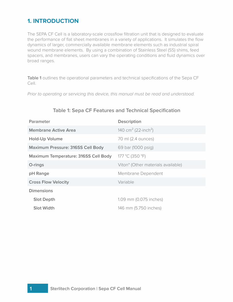
1. INTRODUCTION
The SEPA CF Cell is a laboratory-scale crossflow filtration unit that is designed to evaluate the performance of flat sheet membranes in a variety of applications. It simulates the flow dynamics of larger, commercially available membrane elements such as industrial spiral wound membrane elements. By using a combination of Stainless Steel (SS) shims, feed spacers, and membranes, users can vary the operating conditions and fluid dynamics over broad ranges.
Table 1 outlines the operational parameters and technical specifications of the Sepa CF Cell.
Prior to operating or servicing this device, this manual must be read and understood.
Table 1: Sepa CF Features and Technical Specification
Parameter Description
Membrane Active Area 140 cm² (22-inch²)
Hold-Up Volume 70 ml (2.4 ounces)
Maximum Pressure: 316SS Cell Body 69 bar (1000 psig)
Maximum Temperature: 316SS Cell Body 177 °C (350 °F)
O-rings Viton* (Other materials available)
pH Range Membrane Dependent
Cross Flow Velocity Variable
Dimensions
Slot Depth 1.09 mm (0.075 inches)
Slot Width 146 mm (5.750 inches)
Sterlitech Corporation | Sepa CF Cell Manual1
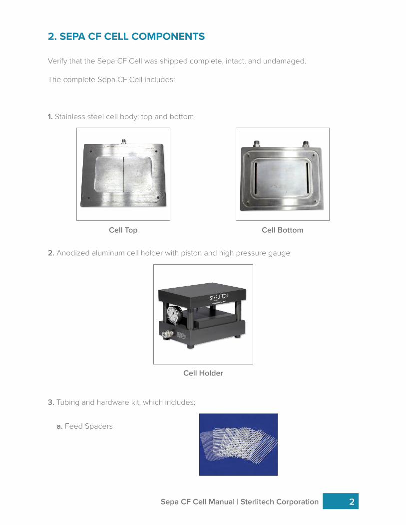
2. SEPA CF CELL COMPONENTS
Verify that the Sepa CF Cell was shipped complete, intact, and undamaged.
The complete Sepa CF Cell includes:
1. Stainless steel cell body: top and bottom
2. Anodized aluminum cell holder with piston and high pressure gauge
3. Tubing and hardware kit, which includes:
Cell Top Cell Bottom
Sepa CF Cell Manual | Sterlitech Corporation 2
Cell Holder
a. Feed Spacers
2.1 ADDITIONAL EQUIPMENT
The Sepa CF Cell also requires additional equipment to be operated, which are sold separately:
• Hydraulic hand pump to pressurize the cell holder• Feed Pump• Feed Tank• Filtration membrane packs• Assortments of shims and additional spacers
Sterlitech Corporation | Sepa CF Cell Manual3
5. O-rings (2)
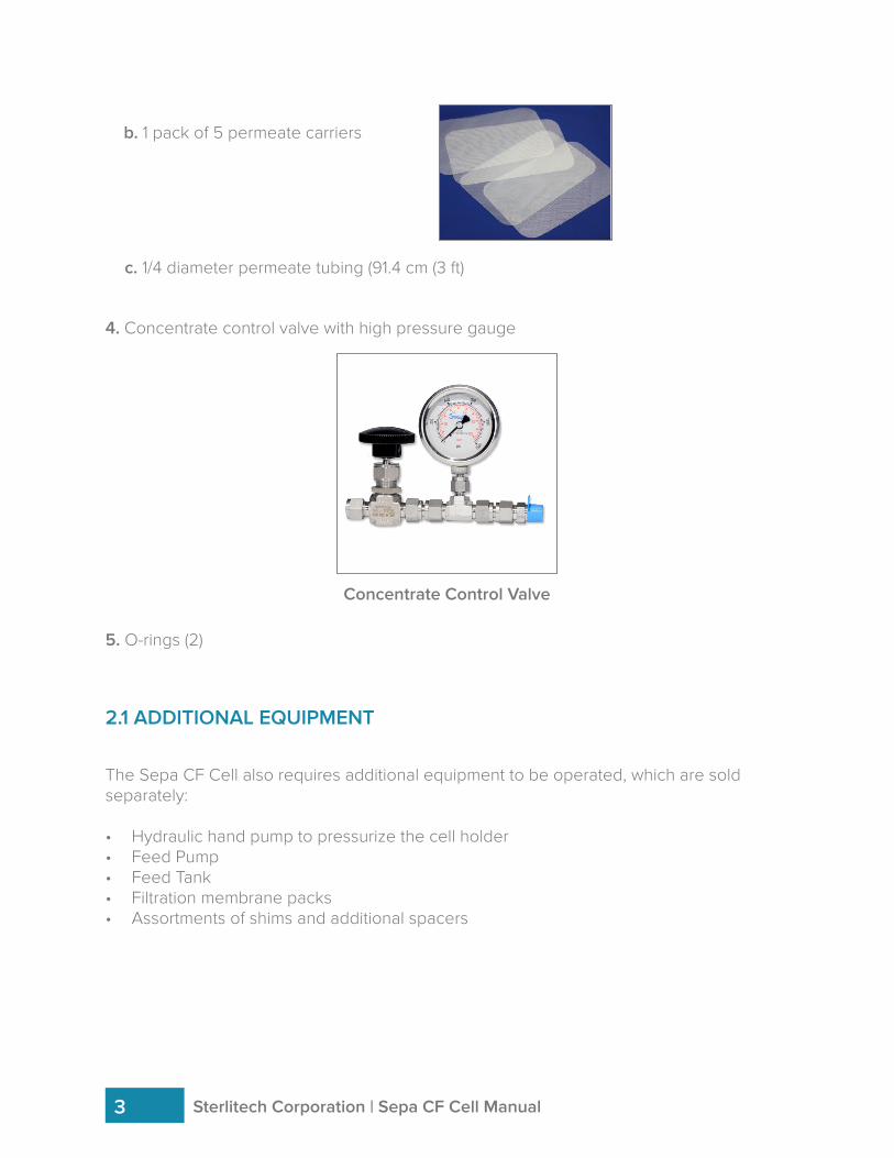
4. Concentrate control valve with high pressure gauge
b. 1 pack of 5 permeate carriers
c. 1/4 diameter permeate tubing (91.4 cm (3 ft)
Concentrate Control Valve
3. SEPA CF CELL ASSEMBLY
After verifying that all of the necessary components were shipped and present, you can begin the assembly of the Sepa CF Cell.
3.1 CELL BODY ASSEMBLY
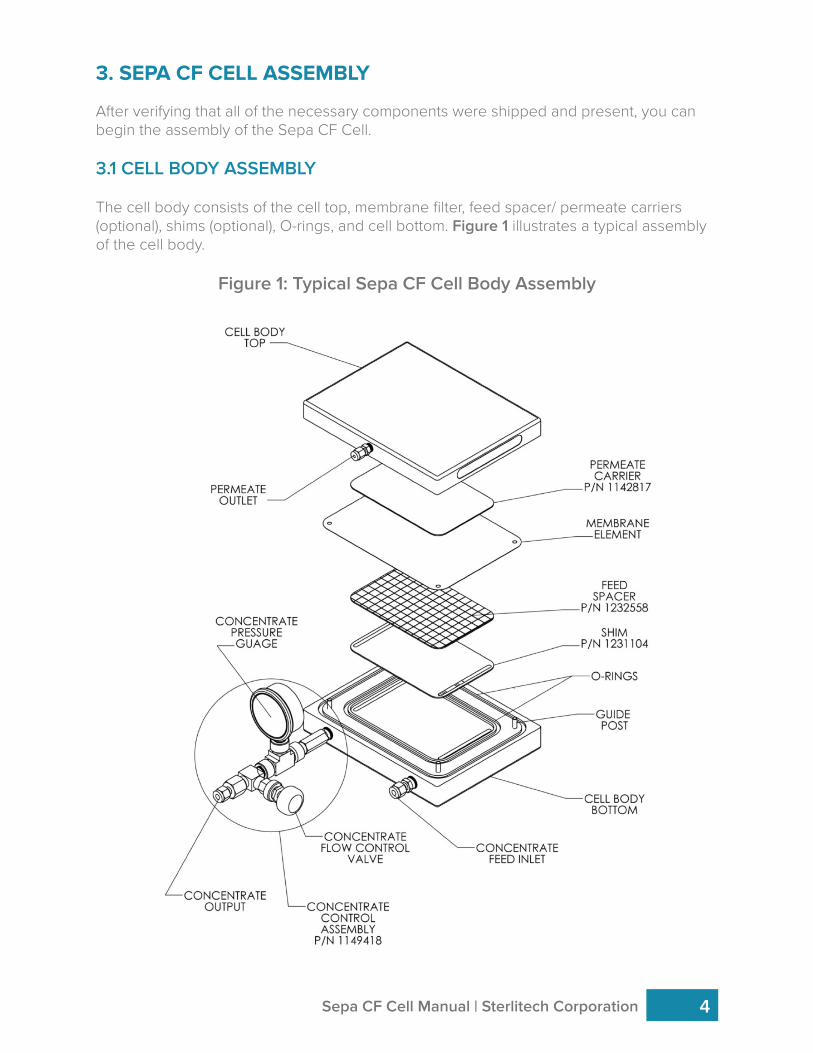
The cell body consists of the cell top, membrane filter, feed spacer/ permeate carriers (optional), shims (optional), O-rings, and cell bottom. Figure 1 illustrates a typical assembly of the cell body.
Figure 1: Typical Sepa CF Cell Body Assembly
Sepa CF Cell Manual | Sterlitech Corporation 4
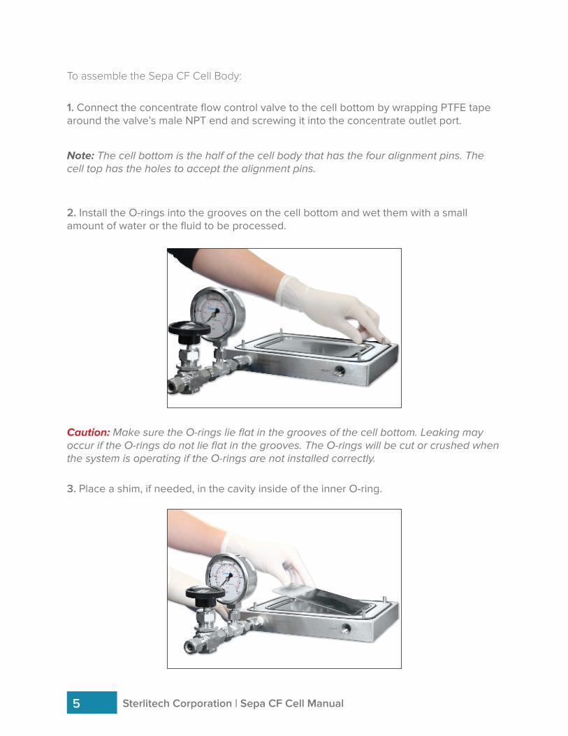
To assemble the Sepa CF Cell Body:
2. Install the O-rings into the grooves on the cell bottom and wet them with a small amount of water or the fluid to be processed.
1. Connect the concentrate flow control valve to the cell bottom by wrapping PTFE tape around the valve’s male NPT end and screwing it into the concentrate outlet port.
Caution: Make sure the O-rings lie flat in the grooves of the cell bottom. Leaking may occur if the O-rings do not lie flat in the grooves. The O-rings will be cut or crushed when the system is operating if the O-rings are not installed correctly.
Note: The cell bottom is the half of the cell body that has the four alignment pins. The cell top has the holes to accept the alignment pins.
3. Place a shim, if needed, in the cavity inside of the inner O-ring.
Sterlitech Corporation | Sepa CF Cell Manual5
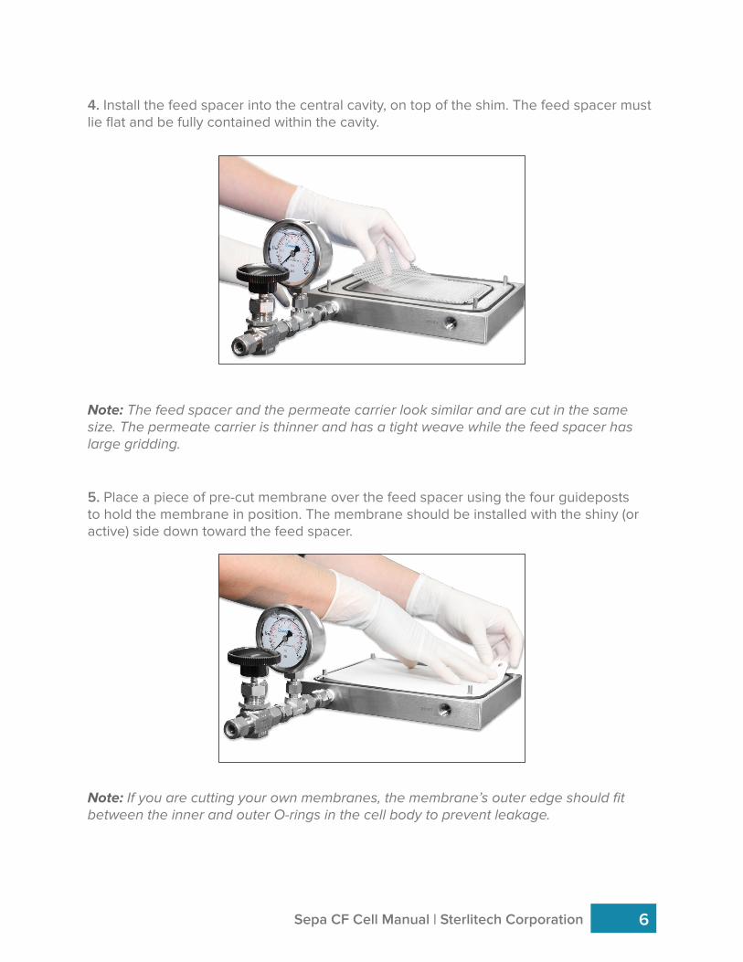
4. Install the feed spacer into the central cavity, on top of the shim. The feed spacer must lie flat and be fully contained within the cavity.
Sepa CF Cell Manual | Sterlitech Corporation 6
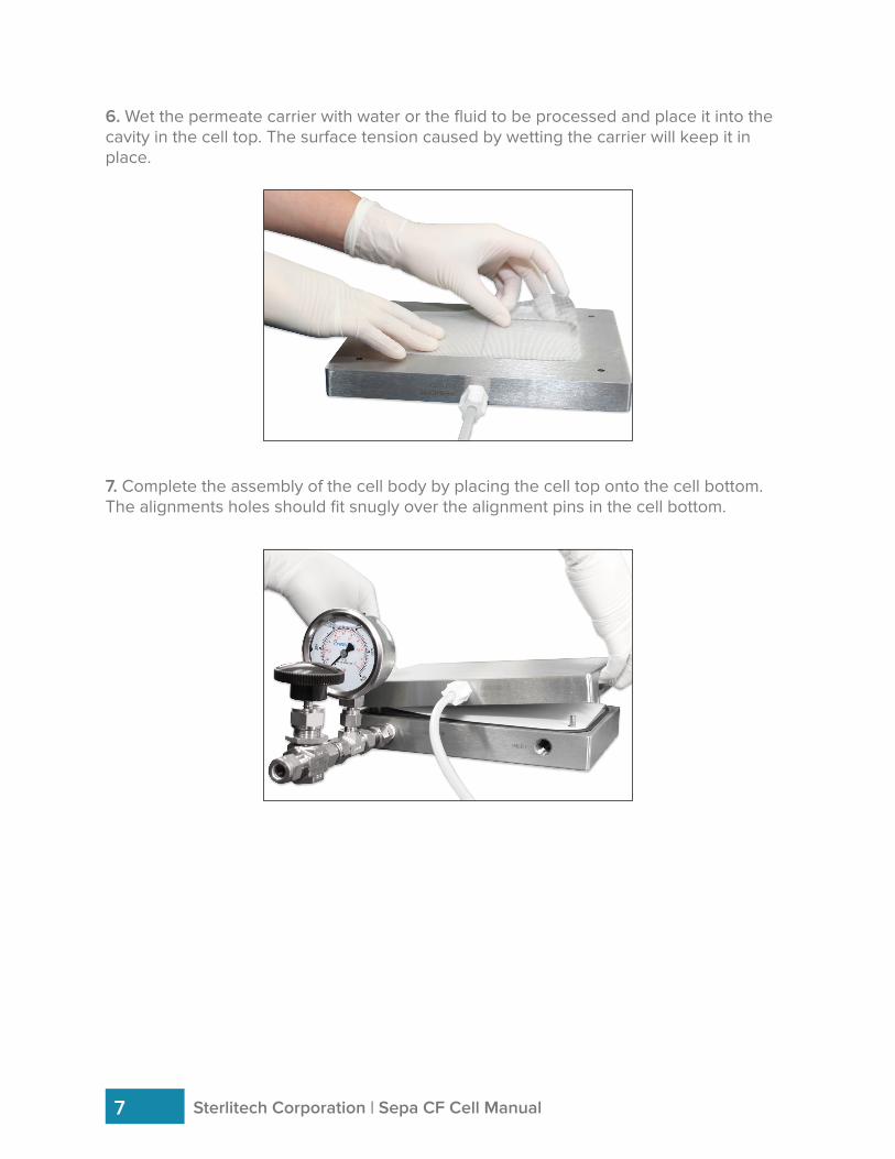
5. Place a piece of pre-cut membrane over the feed spacer using the four guideposts to hold the membrane in position. The membrane should be installed with the shiny (or active) side down toward the feed spacer.
Note: If you are cutting your own membranes, the membrane’s outer edge should fit between the inner and outer O-rings in the cell body to prevent leakage.
Note: The feed spacer and the permeate carrier look similar and are cut in the same size. The permeate carrier is thinner and has a tight weave while the feed spacer has large gridding.
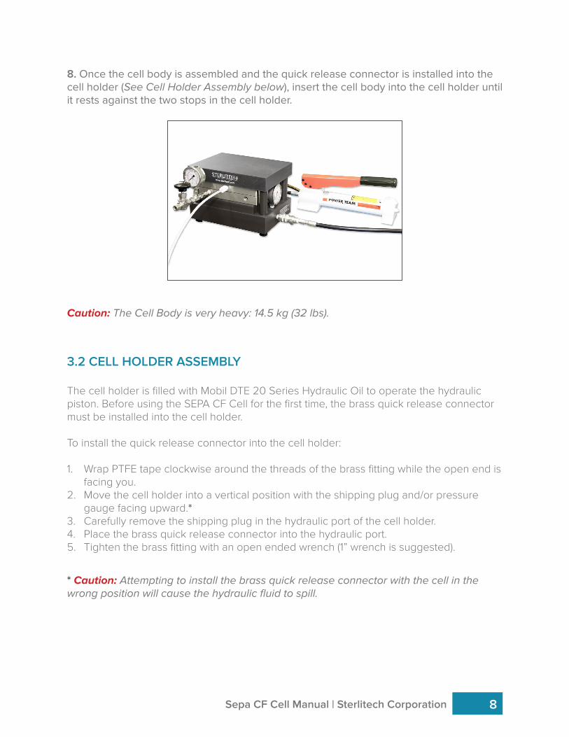
6. Wet the permeate carrier with water or the fluid to be processed and place it into the cavity in the cell top. The surface tension caused by wetting the carrier will keep it in place.
Sterlitech Corporation | Sepa CF Cell Manual7
7. Complete the assembly of the cell body by placing the cell top onto the cell bottom. The alignments holes should fit snugly over the alignment pins in the cell bottom.
Caution: The Cell Body is very heavy: 14.5 kg (32 lbs).
* Caution: Attempting to install the brass quick release connector with the cell in the wrong position will cause the hydraulic fluid to spill.
3.2 CELL HOLDER ASSEMBLY
The cell holder is filled with Mobil DTE 20 Series Hydraulic Oil to operate the hydraulic piston. Before using the SEPA CF Cell for the first time, the brass quick release connector must be installed into the cell holder.
To install the quick release connector into the cell holder:
1. Wrap PTFE tape clockwise around the threads of the brass fitting while the open end is facing you.
2. Move the cell holder into a vertical position with the shipping plug and/or pressure gauge facing upward.*
3. Carefully remove the shipping plug in the hydraulic port of the cell holder.4. Place the brass quick release connector into the hydraulic port.5. Tighten the brass fitting with an open ended wrench (1” wrench is suggested).
Sepa CF Cell Manual | Sterlitech Corporation 8
8. Once the cell body is assembled and the quick release connector is installed into the cell holder (See Cell Holder Assembly below), insert the cell body into the cell holder until it rests against the two stops in the cell holder.
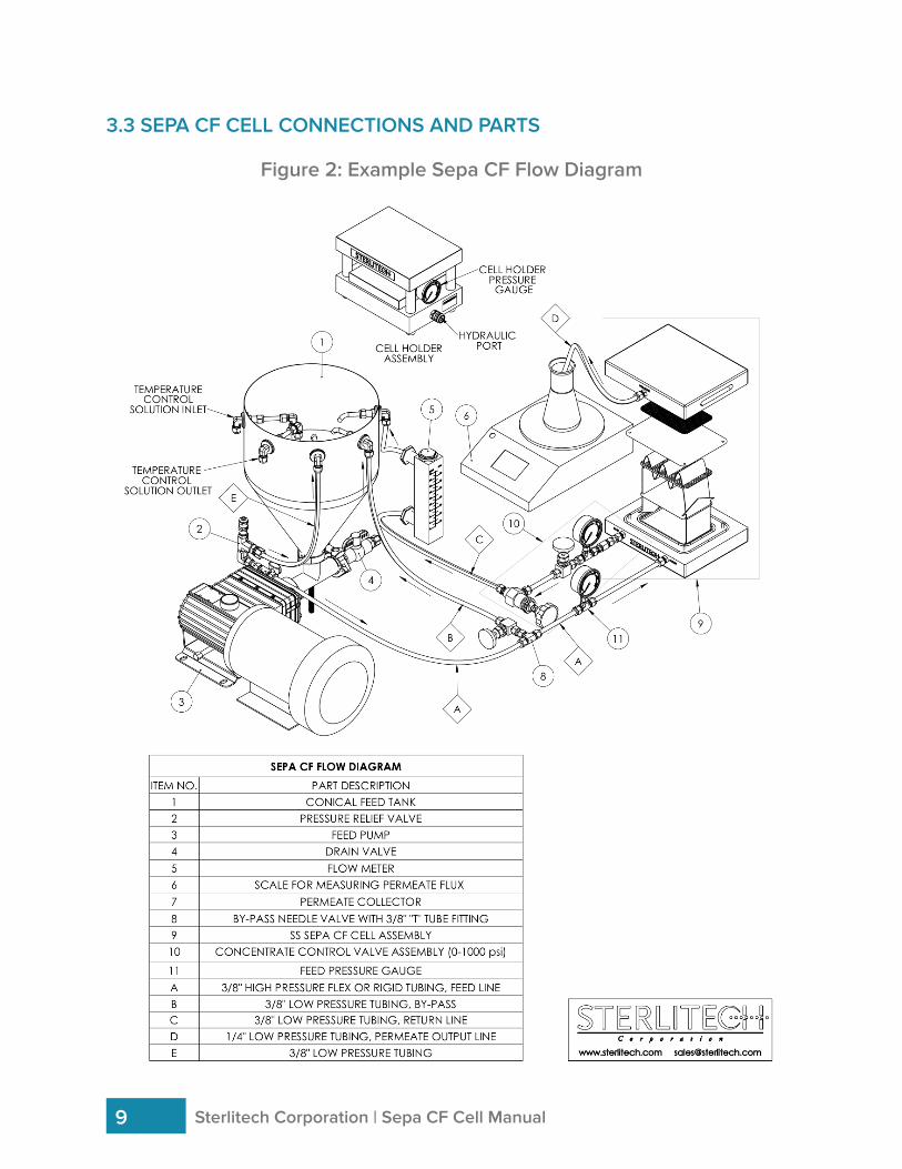
Figure 2: Example Sepa CF Flow Diagram
Sterlitech Corporation | Sepa CF Cell Manual9
3.3 SEPA CF CELL CONNECTIONS AND PARTS
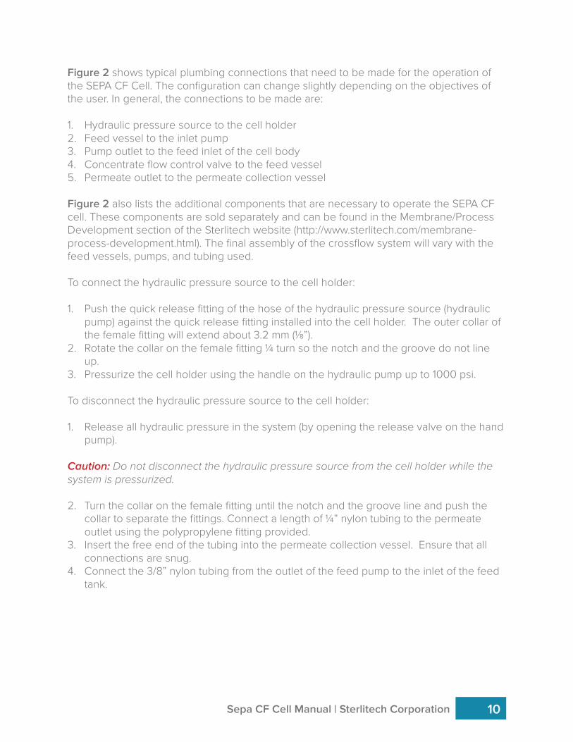
Figure 2 shows typical plumbing connections that need to be made for the operation of the SEPA CF Cell. The configuration can change slightly depending on the objectives of the user. In general, the connections to be made are:
1. Hydraulic pressure source to the cell holder2. Feed vessel to the inlet pump3. Pump outlet to the feed inlet of the cell body4. Concentrate flow control valve to the feed vessel5. Permeate outlet to the permeate collection vessel
Figure 2 also lists the additional components that are necessary to operate the SEPA CF cell. These components are sold separately and can be found in the Membrane/Process Development section of the Sterlitech website (http://www.sterlitech.com/membrane-process-development.html). The final assembly of the crossflow system will vary with the feed vessels, pumps, and tubing used.
To connect the hydraulic pressure source to the cell holder:
1. Push the quick release fitting of the hose of the hydraulic pressure source (hydraulic pump) against the quick release fitting installed into the cell holder. The outer collar of the female fitting will extend about 3.2 mm (⅛”).
2. Rotate the collar on the female fitting ¼ turn so the notch and the groove do not line up.
3. Pressurize the cell holder using the handle on the hydraulic pump up to 1000 psi.
To disconnect the hydraulic pressure source to the cell holder:
1. Release all hydraulic pressure in the system (by opening the release valve on the hand pump).
Caution: Do not disconnect the hydraulic pressure source from the cell holder while the system is pressurized.
2. Turn the collar on the female fitting until the notch and the groove line and push the collar to separate the fittings. Connect a length of ¼” nylon tubing to the permeate outlet using the polypropylene fitting provided.
3. Insert the free end of the tubing into the permeate collection vessel. Ensure that all connections are snug.
4. Connect the 3/8” nylon tubing from the outlet of the feed pump to the inlet of the feed tank.
Sepa CF Cell Manual | Sterlitech Corporation 10
4. OPERATION OF THE SEPA CF CELL
To operate the Sepa CF Cell:
1. Set the feed pressure less than or equal to the piston pressure on the cell holder/cell body and turn the feed flow pump on.
Note: A good starting point may be to set the system at 1.7 bar (25 psig) pressure for ultrafiltration, 17.2 bar (250 psig) for reverse osmosis, and 2–3 Lpm (0.5–0.8 gpm) concentrate flow. If this does not produce the desired results then the parameters can easily be adjusted and different membranes can be used.
2. Verify the feed pressure by comparing the reading on the piston cell holder pressure gauge to the reading on the concentrate pressure gauge.
3. Adjust the concentrate flow control valve to obtain the desired pressure and flow. Experimentation enables you to determine the optimum settings for pressure, flow rate, and shim/spacer combination to use on the chosen membrane and the fluid being processed.
To replace a membrane filter:
1. Turn the pumps OFF.
2. Turn the pressure relief valve knob on the hydraulic pump counterclockwise to release the hydraulic pressure in the system.
3. Slide the cell out of the cell holder.
4. Separate the cell body top from the cell bottom.
5. Remove the membrane.
6. Install the new membrane (and, if necessary, spacers/permeate carrier).
7. Reassemble the cell top and bottom.
8. Insert the cell in the cell holder.
9. Pressurize the cell holder to 1000 psi using the hand pump.
10. Turn the flow pumps on.
Once the SEPA CF Cell has been assembled and connected to a feed system, it can be used in variety of applications that includes reverse osmosis, ultrafiltration, nanofiltration, and microfiltration.
Sterlitech Corporation | Sepa CF Cell Manual11
Sepa CF Cell Manual | Sterlitech Corporation 12
5. SUPPLEMENTARY OPERATING INFORMATION
Other parameters such as viscosity, pressure, and suspended solids may also affect performance/operation. Experimentation with the SEPA CF Cell can help predict the best operating parameters. If your pump is delivering too much flow, a portion of the flow can be diverted back to the feed container before entering the feed inlet of the cell body. This requires installation of an optional bypass valve and fitting on the pump outlet (Figure 2, #4), which is not supplied with the system.
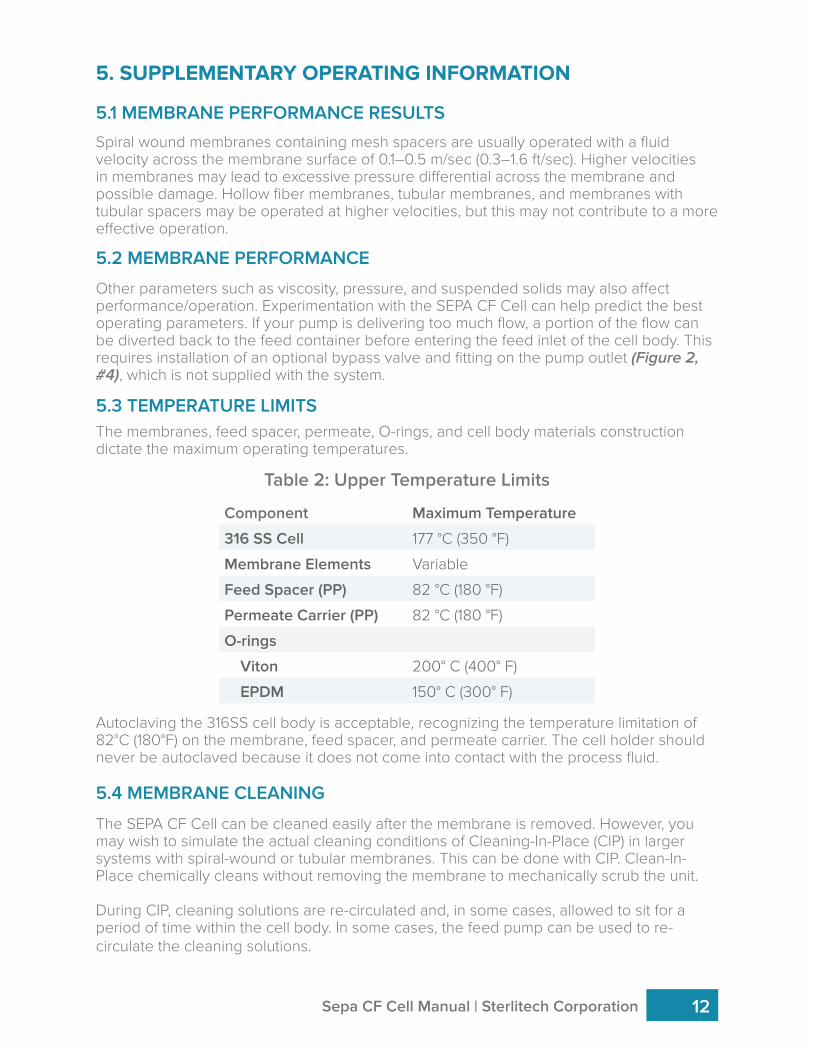
The membranes, feed spacer, permeate, O-rings, and cell body materials construction dictate the maximum operating temperatures.
5.2 MEMBRANE PERFORMANCE
5.3 TEMPERATURE LIMITS
Table 2: Upper Temperature Limits
Component Maximum Temperature
316 SS Cell 177 °C (350 °F)
Membrane Elements Variable
Feed Spacer (PP) 82 °C (180 °F)
Permeate Carrier (PP) 82 °C (180 °F)
O-rings
Viton 200° C (400° F)
EPDM 150° C (300° F)
5.4 MEMBRANE CLEANING
5.1 MEMBRANE PERFORMANCE RESULTSSpiral wound membranes containing mesh spacers are usually operated with a fluid velocity across the membrane surface of 0.1–0.5 m/sec (0.3–1.6 ft/sec). Higher velocities in membranes may lead to excessive pressure differential across the membrane and possible damage. Hollow fiber membranes, tubular membranes, and membranes with tubular spacers may be operated at higher velocities, but this may not contribute to a more effective operation.
Autoclaving the 316SS cell body is acceptable, recognizing the temperature limitation of 82°C (180°F) on the membrane, feed spacer, and permeate carrier. The cell holder should never be autoclaved because it does not come into contact with the process fluid.
The SEPA CF Cell can be cleaned easily after the membrane is removed. However, you may wish to simulate the actual cleaning conditions of Cleaning-In-Place (CIP) in larger systems with spiral-wound or tubular membranes. This can be done with CIP. Clean-In-Place chemically cleans without removing the membrane to mechanically scrub the unit.
During CIP, cleaning solutions are re-circulated and, in some cases, allowed to sit for a period of time within the cell body. In some cases, the feed pump can be used to re-circulate the cleaning solutions.
6. ACCESSORY AND SPARE PART ORDERING INFORMATION
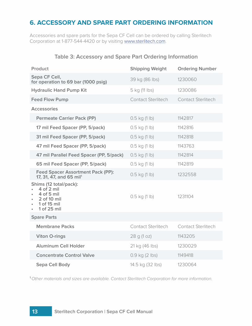
Accessories and spare parts for the Sepa CF Cell can be ordered by calling Sterlitech Corporation at 1-877-544-4420 or by visiting www.sterlitech.com.
Table 3: Accessory and Spare Part Ordering Information
Product Shipping Weight Ordering Number
Sepa CF Cell,for operation to 69 bar (1000 psig) 39 kg (86 lbs) 1230060
Hydraulic Hand Pump Kit 5 kg (11 lbs) 1230086
Feed Flow Pump Contact Sterlitech Contact Sterlitech
Accessories
Permeate Carrier Pack (PP) 0.5 kg (1 lb) 1142817
17 mil Feed Spacer (PP, 5/pack) 0.5 kg (1 lb) 1142816
31 mil Feed Spacer (PP, 5/pack) 0.5 kg (1 lb) 1142818
47 mil Feed Spacer (PP, 5/pack) 0.5 kg (1 lb) 1143763
47 mil Parallel Feed Spacer (PP, 5/pack) 0.5 kg (1 lb) 1142814
65 mil Feed Spacer (PP, 5/pack) 0.5 kg (1 lb) 1142819
Feed Spacer Assortment Pack (PP):17, 31, 47, and 65 mil1 0.5 kg (1 lb) 1232558
Shims (12 total/pack):• 4 of 2 mil• 4 of 5 mil• 2 of 10 mil• 1 of 15 mil• 1 of 25 mil
0.5 kg (1 lb) 1231104
Spare Parts
Membrane Packs Contact Sterlitech Contact Sterlitech
Viton O-rings 28 g (1 oz) 1143205
Aluminum Cell Holder 21 kg (46 lbs) 1230029
Concentrate Control Valve 0.9 kg (2 lbs) 1149418
Sepa Cell Body 14.5 kg (32 lbs) 1230064
1 Other materials and sizes are available. Contact Sterlitech Corporation for more information.
Sterlitech Corporation | Sepa CF Cell Manual13
Sepa CF Cell Manual | Sterlitech Corporation 14
7. RETURN MATERIAL AUTHORIZATION
8. WARRANTY
9. TECHNICAL ASSISTANCE
If materials are to be returned to Sterlitech for repair, evaluation, or warranty consideration, a Return Material Authorization (RMA) number and form must be obtained from Sterlitech prior to the return. Contact Sterlitech’s Customer Service Department for these forms.
The form must be completed and returned with the material. Be sure to include a complete, detailed written reason for the return. Also, include serial numbers, installation and removal dates, and any other pertinent information that is available. Sepa FO Cells have a serial number imprinted on the cell bottom.
Indicate the proposed disposition of the material, and reference the RMA number on all packages or cartons. All material must be shipped to Sterlitech with freight prepared by the customer.
The following is made in lieu of all other warranties expressed or implied. Sterlitech Corporation guarantees equipment to be free from defects in material and workmanship when operated in accordance with written instructions for a period of one year from receipt. Parts not manufactured by Sterlitech are covered by their manufacturer’s warranties, which are normally for one year.
Manufacturers and Seller’s only obligation shall be to issue credit against the purchase or replacement of equipment proved to be defective in material or workmanship. Neither manufacturer nor seller shall be liable for any injury, loss or damage, direct or indirect, special or consequential, arising out of the use of, misuse, or the inability to use such product.
The information contained herein is based on technical data and tests, which we believe to be reliable, and is intended for use by persons having technical skill at their discretion and risk. Since conditions of use are outside Sterlitech’s control, we can assume no liability whatsoever for results obtained or damages incurred through the application of the data presented.
This information is not intended as a license to operate under, or a recommendation to infringe upon, any patent of Sterlitech or others covering any material or use.
The foregoing may not be altered except by a written agreement signed by officers of the manufacturer.
Please contact us if you have any questions or technical inquiries about our products by calling Sterlitech Corporation at 1-877-544-4420 or by visiting www.sterlitech.com.
APPLICATION STUDY CITATION
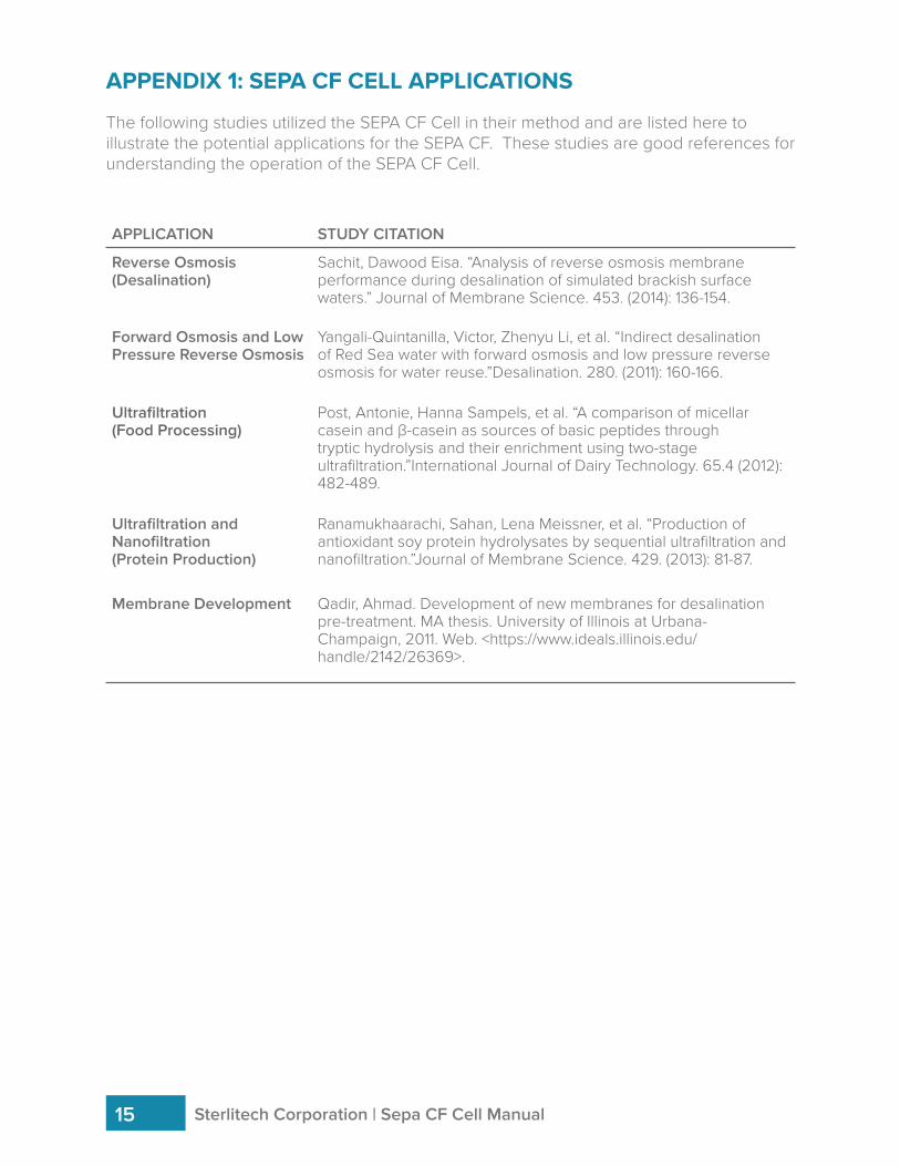
Reverse Osmosis (Desalination)
Sachit, Dawood Eisa. “Analysis of reverse osmosis membrane performance during desalination of simulated brackish surface waters.” Journal of Membrane Science. 453. (2014): 136-154.
Forward Osmosis and Low Pressure Reverse Osmosis
Yangali-Quintanilla, Victor, Zhenyu Li, et al. “Indirect desalination of Red Sea water with forward osmosis and low pressure reverse osmosis for water reuse.”Desalination. 280. (2011): 160-166.
Ultrafiltration(Food Processing)
Post, Antonie, Hanna Sampels, et al. “A comparison of micellar casein and β-casein as sources of basic peptides through tryptic hydrolysis and their enrichment using two-stage ultrafiltration.”International Journal of Dairy Technology. 65.4 (2012): 482-489.
Ultrafiltration and Nanofiltration(Protein Production)
Ranamukhaarachi, Sahan, Lena Meissner, et al. “Production of antioxidant soy protein hydrolysates by sequential ultrafiltration and nanofiltration.”Journal of Membrane Science. 429. (2013): 81-87.
Membrane Development Qadir, Ahmad. Development of new membranes for desalination pre-treatment. MA thesis. University of Illinois at Urbana-Champaign, 2011. Web. <https://www.ideals.illinois.edu/handle/2142/26369>.
APPENDIX 1: SEPA CF CELL APPLICATIONS
The following studies utilized the SEPA CF Cell in their method and are listed here to illustrate the potential applications for the SEPA CF. These studies are good references for understanding the operation of the SEPA CF Cell.
Sterlitech Corporation | Sepa CF Cell Manual15
Sepa CF Cell Manual | Sterlitech Corporation 16
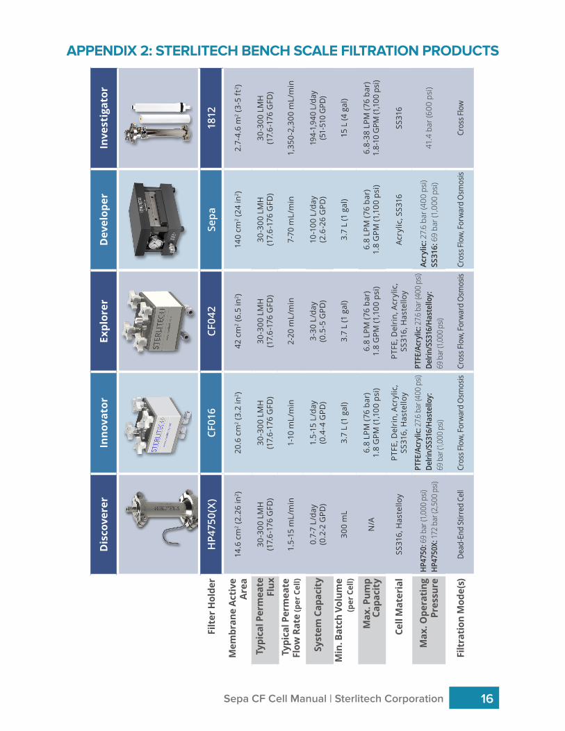
APPENDIX 2: STERLITECH BENCH SCALE FILTRATION PRODUCTS
Dis
cove
rer
Inno
vato
rEx
plor
erD
evel
oper
Inve
stig
ator
Filt
er H
olde
rH
P475
0(X)
CF01
6CF
042
Sepa
1812
Mem
bran
e Ac
tive
Ar
ea14
.6 c
m2 (
2.26
in2 )
20.6
cm
2 (3.
2 in
2 )42
cm
2 (6.
5 in
2 )14
0 cm
2 (24
in2 )
2.7-
4.6
m2 (
3-5
ft2 )
Typi
cal P
erm
eate
Fl
ux30
-300
LM
H(1
7.6-
176
GFD
)30
-300
LM
H(1
7.6-
176
GFD
)30
-300
LM
H(1
7.6-
176
GFD
)30
-300
LM
H(1
7.6-
176
GFD
)30
-300
LM
H(1
7.6-
176
GFD
)
Typi
cal P
erm
eate
Fl
ow R
ate
(per
Cel
l)1.
5-15
mL/
min
1-10
mL/
min
2-20
mL/
min
7-70
mL/
min
1,35
0-2,
300
mL/
min
Syst
em C
apac
ity
0.7-
7 L/
day
(0.2
-2 G
PD)
1.5-
15 L
/day
(0.4
-4 G
PD)
3-30
L/d
ay(0
.5-5
GPD
)10
-100
L/d
ay(2
.6-2
6 G
PD)
194-
1,94
0 L/
day
(51-
510
GPD
)
Min
. Bat
ch V
olum
e(p
er C
ell)
300
mL
3.7
L (1
gal
)3.
7 L
(1 g
al)
3.7
L (1
gal
)15
L (4
gal
)
Max
. Pum
pCa
paci
tyN
/A6.
8 LP
M (7
6 ba
r)1.
8 G
PM (1
,100
psi
)6.
8 LP
M (7
6 ba
r)1.
8 G
PM (1
,100
psi
)6.
8 LP
M (7
6 ba
r)1.
8 G
PM (1
,100
psi
)6.
8-38
LPM
(76
bar)
1.8-
10 G
PM (1
,100
psi
)
Cell
Mat
eria
lSS
316,
Has
tello
yPT
FE, D
elri
n, A
cryl
ic,
SS31
6, H
aste
lloy
PTFE
, Del
rin,
Acr
ylic
, SS
316,
Has
tello
yAc
rylic
, SS3
16SS
316
Max
. Ope
rati
ngPr
essu
reH
P475
0: 6
9 ba
r (1,0
00 p
si)H
P475
0X: 1
72 b
ar (2
,500
psi)
PTFE
/Acr
ylic
: 27.6
bar
(400
psi)
Delri
n/SS
316/
Has
tello
y:
69 b
ar (1
,000
psi)
PTFE
/Acr
ylic
: 27.6
bar
(400
psi)
Delri
n/SS
316/
Has
tello
y:
69 b
ar (1
,000
psi)
Acry
lic: 2
7.6
bar (
400
psi)
SS31
6: 6
9 ba
r (1,
000
psi)
41.4
bar
(600
psi
)
Filt
rati
on M
ode(
s)De
ad-E
nd S
tirre
d Ce
llCr
oss F
low
, For
war
d O
smos
isCr
oss F
low
, For
war
d O
smos
isCr
oss F
low
, For
war
d O
smos
isCr
oss F
low

NOTES:

NOTES:

NOTES:
Founded in 2001 in Kent, WA, Sterlitech Corporation manufactures and markets filtration-focused laboratory products to a broad spectrum of scientific and industrial sectors. Its line of flat sheet membranes and tangential flow cells deliver industry-leading performance and reliable results. Configured for reverse osmosis, nanofiltration, ultrafiltration, and microfiltration applications, Sterlitech’s bench scale test equipment provides the versatility required to innovate.
Sterlitech’s comprehensive line of products is supported by the expertise of its technical specialists who can assist with application-specific product selection, and provide customized solutions where necessary. Unique problem-solving approaches, flexibility, and consistent quality have made Sterlitech Corporation a renowned global provider of filtration products and equipment.
General Corporate Information
Sterlitech Corporation
22027 70th Avenue SKent, WA 98032-1911 USATel: 877-544-4420 or 1-253-437-0844Fax: 1-253-437-0845
Sales [email protected]
Accounts [email protected]
Accounts [email protected]
Press [email protected]

For more information, call (253) 437-0844, (877) 544-4420, or visit www.sterlitech.com
© 2017 Sterlitech Corporation22027 70th Ave. S
Kent, WA 98032-1911 USAPhone: (253) 437-0844
Fax: (253) 437-0845Email: [email protected]