Embed Size (px)
Citation preview

Feasibility Study of an Optically Actuated MR-compatible Active Needle
Seok Chang Ryu, Pierre Renaud, Richard J. Black, Bruce L. Daniel and Mark R. Cutkosky
Abstract— An active needle is proposed for the developmentof MRI guided percutaneous procedures. The needle usesinternal laser heating, conducted via optical fibers, of a shapememory alloy (SMA) actuator to produce bending in the distalsection of the needle. Active bending of the needle as it isinserted allows it to reach small targets while overcomingthe effects of interactions with surrounding tissue, which canotherwise deflect the needle away from its ideal path. The activesection is designed to bend preferentially in one direction underactuation, and is also made from SMA for its combinationof MR and bio-compatibility and its superelastic bendingproperties. A prototype, with a size equivalent to standard 16Gbiopsy needle, exhibits significant bending with a tip rotation ofmore than 10◦. A numerical analysis and experiments provideinformation concerning the required amount of heating andguidance for design of efficient optical heating systems.
I. INTRODUCTION
In the field of interventional radiology, procedures such asbiopsies or punctures are performed using an imaging devicefor guidance. MR scanners are very interesting devices in thiscontext: the radiologist and the patient are not exposed to anyionizing radiation, and the images provided by MR scannershave a high level of contrast and sufficient resolution toidentify small structures such as early stage tumors.
One of the factors limiting today the accuracy of suchgestures is the needle deflection during the insertion [1].The control of the needle path, previously achieved witha rigid body assumption [2], thus evolved towards needlesteering [3] by including needle-tissue interaction models,to predict the behavior of the needle from its geometryand tissue modeling. A simple insertion strategy was intro-duced in [4], the needle is simply rotated by 180◦ whenthe estimated deflection reaches a given threshold. Morecomplex control strategies have subsequently been developedto compensate for needle deflections and even to avoidanatomical obstacles. In [5], [6], the authors propose tomanipulate the needle from its base, outside the patient body,using a robotic system to create forces and moments on theneedle in a similar way to the approach used by clinicians.The stiffness of the tissues at the entry point may limit sucha steering strategy and the robotic system must be designedto provide mobilities in addition to those required for needleinsertion and rotation about the long axis.
S. C. Ryu and M. R. Cutkosky are with the Center for De-sign Research, Stanford University, Stanford, CA, USA, scryu ,[email protected]
P. Renaud is with LSIIT, Strasbourg University - CNRS - INSA, Stras-bourg, France, [email protected]
R. J. Black is with Intelligent Fiber Optic Systems Corporation(www.ifos.com), Santa Clara, CA, USA, [email protected]
Bruce L. Daniel is with the Department of radiology, Stanford University,Stanford, CA, USA, [email protected]
18G Needle tipNiTi tube
SMA wire
Fig. 1. Inner stylet of the proposed active biopsy needle
In [7], [8], [9] relative displacements between concentricneedles, or a prebent needle integrated into a straight cannula,are used to generate a needle trajectory. From a design pointof view, an even simpler approach to steer a needle is touse the asymmetry of the needle to create forces on theneedle during its insertion. The only degrees of freedom tocontrol are then the insertion and the axial rotation of theneedle. Needles with asymmetric bevels are submitted to anunbalanced field of forces during the insertion [10], [11].This phenomenon can be used [12] to steer thin needles.Various complex curves are obtained by combining theneedle insertion and self-rotation movements [13], [14],[15].
In this paper, we propose an extension of needle steeringusing interactions between the needle and the tissues. Thedesign consists of a needle capable of active bending that, incombination with the normal insertion forces and the abilityto rotate the needle about its long axis, allow it to be steeredto reach small tumors or other sites. The actuation systemis entirely compatible with MR imaging and the diameter,at 1.65 mm, is compatible with standard prostate biopsyneedles. In section II, the main design features are intro-duced. An experimental study of the device characteristicsand assessment of the optical heating requirements are thenprovided in section III before concluding on the next stepsin the development of the active needle.
II. ACTIVE NEEDLE DESIGN
A. Related work
The design of an active needle was considered of interestin [16], but no entirely MR-compatible active biopsy needlehas been presented in the literature. Tang et al. developeda needle with a magnetized compliant section near the tip

that is controlled by an external magnetic force [17], whichis not MR-compatible. The thin tip also makes the needlesusceptible to buckling. Yan et al. proposed a smart needleconcept, with a piezoelectric material deposited on the needleto create a continuous bending effect along the needle [18].However, this design is not optimized for steering the needletip during insertion. A tendon-driven steerable needle, basedon a design by PneumRx, was used for lung biopsy [19],where tissues are much less dense than in the prostate.
The principle of an active needle can also be related toactive catheters [20] e.g., for navigation in blood vessels.Several such systems have been developed [21], [22], [23],however their design cannot be directly exploited for anactive needle because of the very different mechanical inter-actions that exist between a needle and tissues, as comparedto the interaction of a catheter with blood flow.
MR-compatible actuation technologies have also beendeveloped for robotic devices. Pneumatic [24] or hy-draulic [25], [26] systems are of interest, the latter present-ing an impressive power/volume ratio. However, integratingsuch technologies in a 1-2 mm diameter needle remains aformidable challenge. Among the actuation technologies thatpresent a high power/volume ratio and MR-compatibility,Shape Memory Alloys (SMA) are of particular interest.By activating thermally a phase transition in the SMAmicrostructure, this material can be used as an actuator.
Joule heating with an electric current is usually adoptedto obtain SMA contraction. An MR-compatible device canbe designed using such an approach [27], however artifactswill be created if actuation and MR imaging are performedconcurrently. Optical heating has been proposed to actuate anSMA forceps for minimally invasive surgery in [28] and forcontraction of an embedded SMA in a smart composite [29].Both studies demonstrate the feasibility of optical SMAactuation.
B. Main design features
1) Principle of an active biopsy needle: A biopsy needleis composed of two main parts: an inner stylet and an outercannula. During a biopsy, the two elements are insertedtogether to reach the biopsy site. Then, the inner stylet isremoved and a biopsy probe is inserted to perform the biopsy.For the proposed device, the active element is the inner styletinitially inserted with the cannula (Fig. 2).
The active element introduces one degree of freedom in theneedle body. Combining active bending with needle insertionand axial rotation movements, it becomes possible to controlthe needle trajectory, following a similar approach as usedpreviously for needle steering with beveled needles.
The inner stylet has a maximum diameter of 1.35 mm, atthe location of the active element, corresponding to a 18Gneedle. With the external cannula, the overall diameter isequal to 1.65mm, which is equivalent to 16G devices usedfor prostate biopsies.
2) SMA for actuation with side optical heating: To pro-mote compactness and effective heat transfer, optical fibersshould run parallel to the needle axis and transmit heat
Clamped0.254 mm SMA
wire
1.02 mm diameterNeedle tip
NiTi tube with slits
A
A
A-A Cross-section
Optical fiber for bending angle sensing
Optical fiber for heating
SMA wire
Multi-lumen tube
Optical fiberfor temperature
sensing
1.37 mm
18 mm
Fig. 2. The inner stylet of an active needle design
Fig. 3. Principle of a Tilted Fiber Bragg Grating
over a finite length of the SMA wire integrated in the axialdirection to get a sufficient displacement. The core diameterof the optical fiber is approximately 100 µm and the laserillumination can produce excessive local heating if it is notdistributed. Solutions for distributed light emission includefiber side polishing and the use of tilted fiber Bragg gratings(TFBG) (Fig. 3). For TFBGs, by removing the fiber cladding,the power emission out of the fiber is maximized, and canreach 55% of the laser power emitted through the fiber [30].In this manner, homogeneous heating can be obtained overlengths up to 50mm [31]. Whether side polishing or TFBGsare used, the addition of thermal cement can enhance transferalong the SMA wire.
3) SMA for MR compatible superelastic structure: Thephase transition of SMA is used for actuation, but also toprovide the flexibility needed to deflect the needle. SMAexhibits a so-called superelastic domain: if the temperatureis high enough, the material is in its austenite phase. Astress increase can then induce a phase transition towardsthe martensite phase. This stress-induced phase transition ischaracterized by a large plateau in the stress-strain domain.We propose here, in a similar way to the needle designintroduced in [32], to use this large elasticity domain for thebody of the active device. This approach allows the needleto achieve high deflections, due to device actuation or tointeraction with tissues, without plastic deformation.
C. Design implementation
1) Integration: The actuation mechanism is based on alaser machined SMA tube and SMA wire. The flexible partof the SMA tube is 25 mm long, with a series of slits withrounded ends (to reduce stress concentrations) on one side(Fig. 2). The number of slits and the distance of 30 µmbetween two consecutive slits are chosen so that the slits

close fully under maximum actuation. In this way, the deviceis always in a configuration for which the wire can generatea tension during its contraction, independent of the externalinteraction forces. Once the slits have closed, the needle be-comes considerably stiffer with respect to additional bendingloads.
In addition to the SMA wire, the SMA tube contains opti-cal fibers for heating and sensing. These elements, presentedin the following section, are inserted in a flexible multi-lumen PTFE tube to obtain and maintain their alignments.High density PTFE material is relatively transparent to mid-infrared light, thereby allowing most of the emitted powerfrom the fibers to reach the SMA wire.
2) Actuation: The SMA wire has a diameter of 0.25 mm.In the current design, a Flexinol wire is chosen (DynalloyInc, Tustin, CA). It can generate, according to the manu-facturer’s specifications, up to 4% of strain when heated to90 ◦C. This temperature is high compared to safe tempera-tures for human tissues, which are on the order of 45 ◦C.However, SMA alloys can receive heat treatments to lowertheir phase transition temperature to 55 ◦C [33]. The outercannula, made of PTFE, introduces an additional thermalinsulation with respect to tissue. Moreover, the bendingactuation will be applied only for short periods of time, toalter the path taken by the needle as it is inserted. Under theseconditions, surrounding tissues should be able to sustain theresulting temperature increases.
Two fibers are embedded in the device to heat the SMAwire. Each of them integrates a side heating element so thatfour heating areas, including the fiber tips, are positionedalong the 18 mm of SMA wire.
3) Sensing: Optical sensing techniques are preferred foran MR-compatible device. In addition to the fibers for actua-tion, the design includes one optical fiber with standard FBGsfor temperature sensing and a second fiber with a treatedsection to increase light loss as a function of curvature.The estimated curvature information can be converted intomechanical strain along the temperature sensing fiber andthe SMA wire. The strain-compensated temperature and thestrain on the SMA wire enable closed loop control of bendingangle. This bending angle can also be used to estimate theneedle shape for instance to track in the image plane theneedle tip.
D. Behavior evaluation using numerical simulation
Steering performance is intrinsically linked to the steeringcontrol strategy and the mechanical properties of the tissuesin interaction with the needle. In this paper, we focuson two intrinsic properties of the device. The first is themaximum deflection of the needle when no force is appliedon the needle tip. This deflection describes the achievabletrajectory correction when using a simple retract-reinsertstrategy, where the needle is almost completely retracted,deflected, and inserted again. Second, the needle stiffness isevaluated to estimate, with a very simple interaction model,the potential behavior of the device in tissue.
Fig. 4. FEA: (a) Tip deflection(scale 1), (b) Von Mises stress in the tube
Finite Element Analysis (FEA) is performed using An-sys software. Superelastic behavior of the SMA can besimulated, in isothermal conditions. As a consequence, wedo not perform a thermo-mechanical simulation but only amechanical simulation, using the SMA wire specificationsprovided by the manufacturer and an experimentally identi-fied Young’s modulus for the tube under the conditions ofinterest.
1) Needle deflection: The SMA wire can be de-scribed [34], [35] as a spring for which displacement dependson the force generated by the phase transition in the materialand the stiffness of the surrounding elements connected to thewire. The deflection is therefore evaluated in 3 steps. First,the stiffness describing the action of the flexible tube againstthe actuating wire is evaluated. Next, the wire behaviorduring contraction is determined. Then, the needle deflectionis found by simulating the bending of the SMA tube withthe determined loading conditions.
The axial wire stiffness is 29 N/mm, and the (asymmet-ric) axial stiffness of the tube is estimated using FEA at43 N/mm. Using the wire description introduced in [34] andthe manufacturer’s specifications, the action of the wire onthe SMA tube can thus be modeled as a 10 N force. Thesimulated needle deflection is represented in Fig. 4 (a). Themaximum deflection is 2.23 mm, which represents a bendingangle of 4.6◦, considering from the FEA results that therotation begins at the first slit on the SMA tube. The VonMises stress reaches 233 MPa in the tube (Fig. 4 (b)). Thesuperelastic plateau is defined for the material by a stress of520 MPa. The superelastic effect is therefore not requiredduring contraction of the wire but may be used to remain inthe elastic regime when external loads are applied.
If a simple retract-reinsert strategy is employed, the deflec-tion angle results in a trajectory deviation of 4.8 mm whenthe needle is inserted by 60 mm, an average length to reachthe prostate during a biopsy [36]. The device performanceseems therefore relevant for the application. As outlinedearlier, its performance in terms of needle steering dependson the control strategy that will be implemented. A moredetailed analysis will be achieved in a future work.
2) Needle stiffness: The SMA tube is not symmetric withrespect to the needle axis. As a consequence, axial forcesexerted by tissues at the tip will induce bending, similarly
to a needle with an asymmetric bevel. Compensating forthis phenomenon is straightforward, and involves rotating theneedle about its long axis. We wish, however, to estimate themagnitude of force that will cause the slits to close up, i.e.beyond which active steering is no longer possible until theneedle is rotated.
The bending stiffness, defined as the ratio between themoment applied on the active part of the needle and its curva-ture, is estimated using FEA at 1493 Nmm2. Let us considera very simple model of interaction with the tissue, with apurely axial force exerted on the needle tip. This force mustthen be equal to 12.6 N to reach the maximum deflectionestimated previously. This value seems satisfactory, as theaxial force only reaches for instance 10 N when puncturinga prostate capsule [37], and is significantly lower after thispuncture. Lateral forces can also induce bending, but theseare compensated via a combination of actuation and needlerotation.
III. PROTOTYPE AND EXPERIMENTATION
A. Prototype
For this preliminary study, only the SMA tube and wireare assembled (Fig. 1). The tube slits are laser machined(Lumenous Inc, Sunnyvale, CA) on a NiTi tube (JohnsonMatthey Medical Inc, West Chester, PA). In this versionof the device, the SMA wire is pressed into the SMAtube using a grooved needle, manufactured using electro-discharge machining.
B. Evaluation of the mechanical behavior
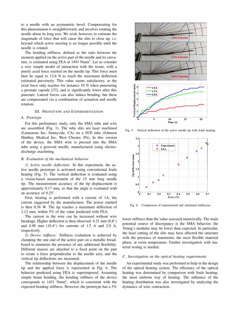
1) Active needle deflection: In this experiment, the ac-tive needle prototype is activated using conventional Jouleheating (Fig. 5). The vertical deflection is evaluated usinga vision-based measurement of the 15 mm long needletip. The measurement accuracy of the tip displacement isapproximately 0.17 mm, so that the angle is evaluated withan accuracy of 0.25◦.
First, heating is performed with a current of 1A, thecurrent suggested by the manufacturer. The power emittedis then 0.36 W. The tip reaches a maximum deflection of2.12 mm, within 5% of the value predicted with FEA.
The current in the wire can be increased without wirebreakage. Higher deflection is then observed: 4.21 mm (8.8◦)and 4.98 mm (10.4◦) for currents of 1.5 A and 2.0 A,respectively.
2) Device stiffness: Stiffness evaluation is achieved byclamping the one end of the active part on a metallic bread-board to minimize the presence of any additional flexibility.Different masses are attached to a fixed point on the partto create a force perpendicular to the needle axis, and thevertical tip deflections are measured.
The relationship between the displacement of the needletip and the applied force is represented in Fig. 6. Thebehavior predicted using FEA is superimposed. Assumingsimple beam bending, the bending stiffness of the devicecorresponds to 1451 Nmm2, which is consistent with theexpected bending stiffness. However, the prototype has a 5%
0 5 10 15 200
1
2
3
4
5
Ver
tical
Dis
plac
emen
t (m
m)
Time (s)
1.0A1.5A2.0A
Fig. 5. Vertical deflection of the active needle tip with Joule heating
3 5
3
3.5
ExperimentFEA
2
2.5
ctio
n [m
m]
1
1.5
Tip
defle
c
0 0.1 0.2 0.3 0.4 0.5 0.6 0.70
0.5
0 0.1 0.2 0.3 0.4 0.5 0.6 0.7
Force (N)
Fig. 6. Comparison of experimental and simulated stiffnesses
lower stiffness than the value assessed numerically. The mainpotential source of discrepancy is the SMA behavior; theYoung’s modulus may be lower than expected. In particular,the laser cutting of the slits may have affected the structurewith the presence of martensite, the most flexible materialphase, at room temperature. Further investigation with ma-terial testing is needed.
C. Investigation on the optical heating requirements
An experimental study was performed to help in the designof the optical heating system. The efficiency of the opticalheating was determined by comparison with Joule heating,the most uniform way of heating. The influence of theheating distribution was also investigated by analyzing thedynamics of wire contraction.

1) The experimental set-up: An apparatus was constructedto assess the heating performance using optical fibers ofa single SMA wire. The apparatus (Fig. 7) is a levermechanism, actuated by the SMA wire, whose displacementis measured using a spring-loaded dial gauge. The dial gaugeapplies a resisting force of approximately 1 N to the lever tip.A 0.25 mm diameter, 40 mm long, Dynalloy wire is used.Measurement resolution is 0.025 mm at the tip of the lever,which makes it possible determine the wire contraction usinga kinematic model with a resolution of 2 µm. To performthe heating, two multimode fibers (105µm core diameter) areconnected to 976nm lasers (Alfalight Inc, Madison, WI). Theuse of two fibers allows a simulation of multi-point heating,albeit less evenly distributed than with TFBGs. The opticalfibers and the SMA wire are positioned in the same plane.The fibers are spaced 15 mm apart and oriented perpendicularto the wire, almost in contact with it.
2) Results: The wire contraction is represented in Fig. 8.The displacements observed when using only one fiber,with two fibers, and after displacing the two fibers 5 mmdistant from the wire. The results are compared to the resultsobtained when the wire is heated uniformly by Joule heatingusing a constant current of 1.4 A, producing 2 W for the40 mm of wire. The dynamics and the amplitude of thecontraction in this case provide a reference for the opticalheating results.
First, the maximum power from the optical fiber tip isevaluated. Above 0.38 W, heating with the fiber tip nearly incontact with the wire leads to the wire breakage due to thesmall spot size.
Using one fiber to perform the heating, the wire contrac-tion is equal to 25% of the displacement obtained with Jouleheating, with a comparable initial contraction rate. This tendsto show that about 10 mm of wire has contracted during the8 seconds of heating.
With two fibers, the total power emitted is 0.76 W.The wire displacement reaches 58% of the 40 mm wirecontraction obtained by Joule heating. In other words, about23 mm of wire is contracted with the optical heating inabout 8 seconds. The initial contraction is faster than with theJoule heating. Since the heating is more localized, the wireis submitted to strong thermal gradients, and the maximumtemperatures exceed those from Joule heating.
When increasing the distance between the fibers and theSMA wire, the wire no longer receives most of the poweremitted by the fiber tips. Measurement with a power metershows that each fiber sends 0.16 W to approximately 5 mmof wire. The heating effect is still significant: the wire dis-placement is slightly greater than obtained with a single fiberin contact, with comparable dynamics. This configuration,similar to the effect that can be obtained using side polishingor TFBGs, appears promising: the power for optical heatingremains limited, with 0.32 W to obtain a contraction ofmore than 10 mm of wire, and heating along the lengthof the wire, instead of spot heating, limits overheating thatcan lead to breakage. With refinement of the optical heatingsystem and of the transfer of power into the wire, the bending
SMA wire
Fiber holder
Optical fibers
Dial gauge
Displacementamplifying lever
Fig. 7. Experimental set-up for the evaluation of the optical heating
1.2
1
Single fiber (contact, 0.38W)
Two fibers (contact, 0.76W)
0.8
(mm
) Joule heating (2W)
Two fibers (5 mm, 0.32W)
0.6
emen
t (
0.4
Dis
plac
e
0.2
D0
0 2 4 6 8Time (s)
Fig. 8. Comparison of wire displacement during optical and Joule heating
requirements can be satisfied.
IV. CONCLUSION
In this paper, a new design for an MR-compatible activeneedle is proposed. Combining optical heating and SMA,for its shape memory and superelastic effects, allows us topropose a device matching the size of a standard biopsyneedle with significant active deflection capabilities. A firstprototype is presented, with an evaluation of its perfor-mances. The potential of optical heating is then experi-mentally evaluated. Information about the required powerfor the SMA wire heating has been determined, and theeffect of uniformity of heating are evaluated. Further workwill focus on the integration of the optical heating systemto actuate the needle with SMA wires, with investigationon fiber polishing or fiber coating with a thermal layer asadditional solutions to TFBGs. The development of closed-loop bending and temperature control strategies adapted tothe steering capabilities of the device will then be studied.Next, the prototype will be tested under closed-loop controlin tissue phantoms in an MR scanner.
V. ACKNOWLEDGMENTS
S. C. Ryu was supported by a seed grant program ofCenter for Biomedical Imaging at Stanford and P. Renaudby a Fulbright fellowship at Stanford University.

REFERENCES
[1] P. Blumenfeld, N. Hata, S. DiMaio, K. Zou, S. Haker, G. Fichtinger,and C. Tempany, “Transperinal prostate biopsy under magnetic reso-nance image guidance: A needle placement accuracy study,” Journalof Magnetic Resonance Imaging, vol. 26, pp. 688–694, 2007.
[2] E. Buonocore and G. Skipper, “Steerable real-time sonographicallyguided needle biopsy,” Am. J. Roentgenol., vol. 136, no. 2, pp. 387–392, 1981.
[3] S. DiMaio and S. Salcudean, “Needle steering and model-based tra-jectory planning,” Medical Image Computing and Computer-AssistedIntervention, 2003.
[4] N. Abolhassani, R. Patel, and F. Ayazi, “Effects of different insertionmethods on reducing needle deflection,” in Proc. 29th Annual Interna-tional Conference of the IEEE Engineering in Medicine and BiologySociety EMBS 2007, 2007, pp. 491–494.
[5] S. P. DiMaio and S. E. Salcudean, “Needle steering and motion plan-ning in soft tissues,” IEEE Transactions on Biomedical Engineering,vol. 52, no. 6, pp. 965–974, June 2005.
[6] D. Glozman and M. Shoham, “Image-guided robotic flexible needlesteering,” IEEE Transactions on Robotics, vol. 23, no. 3, pp. 459–467,2007.
[7] P. Sears and P. Dupont, “A steerable needle technology using curvedconcentric tubes,” in Proc. IEEE/RSJ International Conference onIntelligent Robots and Systems, 2006, pp. 2850–2856.
[8] S. Okazawa, R. Ebrahimi, J. Chuang, S. E. Salcudean, and R. Rohling,“Hand-held steerable needle device,” IEEE/ASME Transactions onMechatronics, vol. 10, no. 3, pp. 285–296, 2005.
[9] I. Webster, R. J., A. M. Okamura, and N. Cowan, “Toward activecannulas: Miniature snake-like surgical robots,” in Proc. IEEE Inter-national Conference on Int. Robots and Systems, 2006, pp. 2857–2863.
[10] H. Kataoka, T. Washio, M. Audette, and K. Mizuhara, “A model forrelations between needle deflection, force, and thickness on needlepenetration,” in Medical Image Computing and Computer-AssistedIntervention, 2001, pp. 966–974.
[11] A. M. Okamura, C. Simone, and M. D. O’Leary, “Force modeling forneedle insertion into soft tissue,” IEEE Transactions on BiomedicalEngineering, vol. 51, no. 10, pp. 1707–1716, Oct. 2004.
[12] R. Alterovitz, K. Goldberg, and A. Okamura, “Planning for steerablebevel-tip needle insertion through 2d soft tissue with obstacles,” inProc. IEEE International Conference on Robotics and AutomationICRA 2005, 2005, pp. 1640–1645.
[13] J. A. Engh, G. Podnar, S. Y. Khoo, and C. N. Riviere, “Flexible needlesteering system for percutaneous access to deep zones of the brain,” inProc. IEEE 32nd Annual Northeast Bioengineering Conference, 2006,pp. 103–104.
[14] J. Ding, D. Stoianovici, D. Petrisor, P. Mozer, R. Avila, L. Ibanez,W. Turner, D. Yankelvitz, E. Wilson, F. Banovac, and K. Cleary,“Medical needle steering for lung biopsy: Experimental results intissue phantoms using a robotic needle driver,” in Proc. 8th IEEEInternational Conference on BioInformatics and BioEngineering BIBE2008, 2008, pp. 1–5.
[15] S. Misra, K. B. Reed, W. S. Benjamin, K. T. Ramesh, and A. M.Okamura, “Observations and models for needle-tissue interactions,”in Proc. IEEE Int. Conf. on Robotics and Automation, 2009.
[16] B. N. Li, P. B. Nguyen, S. H. Ong, J. Qin, L. J. Yang, and C. K. Chui,“Image processing and modeling for active needle steering in liversurgery,” in Proc. Int. Asia Conf. Informatics in Control, Automationand Robotics CAR ’09, 2009, pp. 306–310.
[17] L. Tang, Y. Chen, and X. He, “Magnetic force aided compliantneedle navigation and needle performance analysis,” in Proc. IEEEInternational Conference on Robotics and Biomimetics ROBIO 2007,15–18 Dec. 2007, pp. 612–616.
[18] K. Yan, T. Podder, W. S. Ng, and Y. Yu, “Smart needle for percuta-neous surgery: Influential factor investigation,” in Proc. 29th AnnualInternational Conference of the IEEE Engineering in Medicine andBiology Society EMBS 2007, 2007, pp. 461–464.
[19] L. B. Kratchman, M. M. Rahman, J. R. Saunders, P. J. Swaney, andR. J. Webster III, “Toward robotic needle steering in lung biopsy: Atendon-actuated approach,” Proc. of SPIE, vol. 7964, 2011.
[20] G. Lim, K. Park, M. Sugihara, K. Minami, and M. Esashi, “Future ofactive catheters,” Sensors and Actuators A: Physical, vol. 56, no. 1-2,pp. 113 – 121, 1996.
[21] Y. Haga, Y. Tanahashi, and M. Esashi, “Small diameter active catheterusing shape memory alloy,” in Proc. Workshop The Eleventh AnnualInt Micro Electro Mechanical Systems MEMS 98, 1998, pp. 419–424.
[22] K. Ikuta, H. Ichikawa, K. Suzuki, and D. Yajima, “Multi-degree offreedom hydraulic pressure driven safety active catheter,” in Proc.IEEE Int. Conf. Robotics and Automation ICRA 2006, 2006, pp. 4161–4166.
[23] A. T. Tung, B.-H. Park, G. Niemeyer, and D. H. Liang, “Laser-machined shape memory alloy actuators for active catheters,”IEEE/ASME Transactions on Mechatronics, vol. 12, no. 4, pp. 439–446, 2007.
[24] G. Fischer, I. Iordachita, C. Csoma, J. Tokuda, S. DiMaio, C. Tempany,N. Hata, and G. Fichtinger, “MRI-compatible pneumatic robot fortransperineal prostate needle placement,” IEEE/ASME Transactions onMechatronics, vol. 13, no. 3, pp. 295–305, 2008.
[25] G. Ganesh, R. Gassert, E. Burdet, and H. Bleuler, “Dynamics andcontrol of an MRI compatible master-slave system with hydrostatictransmission,” in IEEE Conf. on Robotics and Automation, 2004, pp.1288–1294.
[26] H. Okayasu, J. Okamoto, M. Fujie, M. Umezu, and H. Iseki, “Devel-opment of a hydraulic-driven flexible manipulator for neurosurgery,”International Congress Series, vol. 1256, pp. 607–612, 2003.
[27] W. Pappafotis, N. ad Bejgerowki, R. Gullapalli, J. Simard, S. Gupta,and J. Desai, “Towards design and fabrication of a miniature MRI-compatible robot for applications in neurosurgery,” in ASME Mecha-nisms and Robotics Conference, 2008.
[28] Y. Nakamura and K. Shimizu, “Optical drive of sma active forceps forminimally invasive surgery,” Journal of the Robotics Society of Japan,vol. 17, no. 3, pp. 439–448, 1999.
[29] Z.-m. Zhao, Y.-m. Chen, and X.-l. Yu, “The parameters selectionof sma optically activated and its application,” Journal of WuhanUniversity of Technology-Materials Science Edition, vol. 17, 2002.
[30] L. Seihyoung, Y. Shinyoung, J. L. Jong, H. Y. Chong, and S. K. Hyun,“Optical signal is coupled out using fiber grating,” SPIE, 2007.
[31] P. Westbrook, K. S. Feder, and C. G. E., “Fiber-grating distributedlighting for sensing applications,” SPIE, 2008.
[32] I. Webster, R. J., J. Memisevic, and A. M. Okamura, “Design con-siderations for robotic needle steering,” in Proc. IEEE InternationalConference on Robotics and Automation ICRA 2005, 2005, pp. 3588–3594.
[33] Y. Luo, T. Takagi, and K. Matsuzawa, “Thermal responses ofshape memory alloy artificial anal sphincters,” Smart Materialsand Structures, vol. 12, no. 4, p. 533, 2003. [Online]. Available:http://stacks.iop.org/0964-1726/12/i=4/a=304
[34] V. Kode, M. C. Cavusoglu, and M. T. Azar, “Design and characteri-zation of a novel hybrid actuator using shape memory alloy and D.C.motor for minimally invasive surgery applications,” in IEEE Int. Conf.on Mechatronics and Automation, 2005.
[35] S. Kim, E. Hawkes, K. Cho, M. Joda, J. Foley, and R. Wood, “Microartificial muscle fiber using NiTi spring for soft robotics,” in IEEEConf. on Int. Robots and Systems, 2009, pp. 2228–2234.
[36] J.-S. Plante, L. Devita, K. Tadakuma, and S. Dubowsky, MRI Com-patible Device for Robotic Assisted Interventions to Prostate Cancer.John Wiley & Sons, Ltd, 2009, pp. 411–425.
[37] K. Yan, L. Li, J. Joseph, D. Rubens, E. Messing, L. Liao, and L. Yu,“A real-time prostate cancer detection technique using needle insertionforce and patient-specific criteria during percutaneous intervention,”Med Phys, vol. 36, no. 7, 2009.