Embed Size (px)
Citation preview
Dallas Delta Corporation Pty.Ltd.Dallas Delta Corporation Pty.Ltd.102 Albert St. East Brunswick, 3057 Vic.Tel: 613 93877388 Fax: 613 93873128
Email: [email protected]
SENTINELNO BILL INTERFACE
Controller andExtension (Extn) Cards

Dallas Delta Corporation Pty.Ltd.Dallas Delta Corporation Pty.Ltd. Page 2.0Page 2.0
PRODUCT INFORMATION Sentinel No Bill Interface
The Sentinel secured entry telephone was designed to meet the communication needs of today's apartment and office buildings that have a constant need for entry supervision, without the need of a duty guard or monitoring facilities.
The Sentinel connects to the Tenant/Office via the telecommunication network using a single telephone line to call up to 100 different numbers. This eliminates the need for a separate intercom or PABX, both of which require dedicated wiring to each unit and many thousands of dollars in initial and running costs.
Now Dallas Delta Corp. has produced the No Bill Interface for the Sentinel. This means that we have now cut out the ongoing call costs for the Sentinel.
The No Bill Interface connects between the PSTN and the building telephone wiring. All wiring is made to the MDF KRONE terminals ensuring a very easy setup.
Capacity, the unit may be extended to connect up to 1000 rooms.
Multiple entry, Up to nine Sentinels can be connected to the system (optional).
No Call Charges, the Sentinel / No Bill Interface does not require a telephone line to operate.
Call Waiting Tone, this feature is used when the person in the apartment is on another call (PSTN call). The No Bill Interface sends a unique tone, similar to a call waiting tone, to notify that there is someone at the door. This feature is switchable and may be disabled.
Pure Sine Wave Ring Generator, may ring up to 3 telephones in parallel. Distinctive rings make it easy to differentiate between a PSTN call and someone at the Sentinel.
Lift Interface which allows access to the lift and a specific floor. Access time is programmable and expandable to 100 floors. (optional)
Plus all features available to the Sentinel, as referred to in the Sentinel manual.
FEATURES
Dallas Delta Corporation Pty.Ltd.Dallas Delta Corporation Pty.Ltd. Page 3.0Page 3.0
Sentinel No Bill Interface Operation
When a visitor dials a unit occupiers’ number on the Sentinel door station, the unit occupiers’ normal PSTN line is switched out of circuit and the Sentinel is connected instead. The telephone is rung with a ring cadence that is dis-similar to PSTN ring, so the occupier knows that it is a door station call. If there is no answer, the system will stop after approx. 90 seconds.
If the called unit occupiers’ telephone is in use, then a call waiting tone is inserted onto the telephone line. Once the telephone has been placed on hook, it will automatically start ringing at the door station cadence. This feature can be disabled, please refer to page 7 for details.
If the unit occupier is talking to the door station when the occupiers PSTN line starts to ring, a call waiting tone is also injected across the conversation. Once the telephone or Sentinel goes on hook, the telephone will ring as normal.

Dallas Delta Corporation Pty.Ltd.Dallas Delta Corporation Pty.Ltd. Page 4.0Page 4.0
extn 00
extn 01
extn 02
extn XX
Dallas Delta
Enter Number then #
1 2 3 4 5 6 7 8 9 0
1 2 3 4 5 6 7 8 9 0
1 2 3 4 5 6 7 8 9 0
1 2 3 4 5 6 7 8 9 0
BLOCK DIAGRAM
Dallas Delta Corporation Pty. LtdDallas Delta Corporation Pty. Ltd N722
PSTN
SENTINEL
SENTINELCARD
SLAVECARD
-++22Vdc @ 750mA
NO BILL INTERFACE CONTROLLER
VERSION co1.2
Dallas Delta Corporation Pty. LtdDallas Delta Corporation Pty. Ltd N722
Dallas Delta Corporation Pty.Ltd.Dallas Delta Corporation Pty.Ltd.102 Albert St. East Brunswick, 3057 Vic.Tel: 613 93877388 Fax: 613 93873128
Email: [email protected]
N722POWER
PowerSupply
to lift cardif fitted
(optional)
Controller
figure 1.0
Sentinel
INSTALLATION DETAILS (for single Sentinel operation)
STEP 1 - setup extn card addresses
Each individual extn card on the system must have a different address number. A maximum of 100 cards can be used on one system.eg. If 4 cards are supplied, the first card will be set to ‘00’, the second card to ‘01’ the third card to ‘02’ and the fourth card to ‘03’. (please refer to figure 2.0)
extn
No Bill Interface Extn Card
10 9 8 7 6 5 4 3 2 1
PSTN side
05123
6 7 8 9
4
A card number from '00 - 99' must be selected and cannot be the same as any other card on the system.
figure 2.0
LIN
E
PO
WE
R
RE
LA
Y
LIN
E
PO
WE
R
RE
LA
Y
PowerSupply
05123
6 7 8 9
4
Units Tens
BCD1 BCD2

Dallas Delta Corporation Pty.Ltd.Dallas Delta Corporation Pty.Ltd. Page 5.0Page 5.0
STEP 2 - wiring up the KRONE block
The Extn cards plugged into the KRONE blocks must be removed before any wiring may commence. The No Bill Interface is wired between the PSTN and the building wiring.
Figure 3.0 outlines the wiring details of the KRONE block. The PSTN wiring comes in from the top of the KRONE Block and the building internal wiring out the bottom.
1 2 3 4 5 6 7 8 9 0KRONE Block
PSTN 00
Internal line 00
PSTN 01
Internal line 01
PSTN 09
Internal Line 09figure 3.0
INSTALLATION DETAILS continued...
STEP 3 - inserting the Extn cards
Plugging in the cards must be done with extreme care. Make certain that the PSTN side of the card is lined up to the PSTN side of the KRONE block and the LOCAL side of the card is lined up to the LOCAL side of the KRONE block. Line up the cutouts and ensure the card is fully inserted. Make sure that the card with the terminating resistor (usually marked with an ‘X’) is last in line of a multiple card system. The terminating resistor is in circuit when a link is placed over the pins as indicated below. (The termination resistor will supply the correct impedance at the other end of the controller.)
101 2 3 4 5 6 7 8 9 PSTN101 2 3 4 5 6 7 8 9 PSTN
101 2 3 4 5 6 7 8 9 LOCAL
No Bill Interface Extn Card Top view
LED will flash when thecard is operational.
figure 5.0
10 9 8 7 6 5 4 3 2 1
05123
6 7 8 9
4
figure 4
05123
6 7 8 9
4
Units Tens
BCD1 BCD2
J1
Dallas Delta Corporation Pty. Ltd.102 Albert St. East Brunswick, Victoria 3057Ph: 613 9387 7388 Fax: 613 9387 3128
www. dallasdelta.com.au
Termination resistor link

Dallas Delta Corporation Pty.Ltd.Dallas Delta Corporation Pty.Ltd. Page 6.0Page 6.0
STEP 4 - wiring the sentinel to the controller
Connect the 6 way lead from the Sentinel to the Sentinel Junction Box, then connect a 2 way lead from the Controller to the Controller Junction Box. Now connect LINE to LINE between the junction boxes and power to the Sentinel Junction Box.
NO BILL INTERFACE CONTROLLER
Dallas Delta Corporation Pty. LtdDallas Delta Corporation Pty. Ltd N722
PSTN
SENTINEL
SENTINELCARD
EXTENSIONCARD
-++22Vdc @ 750mA
NO BILL INTERFACE CONTROLLER
VERSION co1.2
LED will flash when thecontroller is operational
LIN
E
PO
WE
R
RE
LA
Y
LIN
E
6 W
AY
2 W
AY
SENTINEL
SENTINELJUNCTION BOX
CONTROLLERJUNCTION BOX
figure 6.0
to Extn cards
POWERSUPPLY
POWERSUPPLY
Dallas Delta Corporation Pty. LtdDallas Delta Corporation Pty. Ltd N722
Dallas Delta Corporation Pty.Ltd.Dallas Delta Corporation Pty.Ltd.102 Albert St. East Brunswick, 3057 Vic.Tel: 613 93877388 Fax: 613 93873128
Email: [email protected]
N722POWER
NO BILL INTERFACE CONTROLLER
Dallas Delta
Enter Number then #
INSTALLATION DETAILS continued...

Dallas Delta Corporation Pty.Ltd.Dallas Delta Corporation Pty.Ltd. Page 7.0Page 7.0
STEP 6 - programming numbers into the Sentinel NB. Before any further programming can take place, the 'Lift Relay On Time' of the Sentinel must be
set correctly. OPTION 10 of MODE 1 must be set any where between '1 -9' and must not be '0'. (please refer to page 4 of 'The Sentinel Building Security Telephone' hand Book for details).
The programming of the No bill Interface is made at the Sentinel. The full programming details of the Sentinel are outlined in the Sentinel Manual. Variations necessary for the No Bill Interface are outlined as follows;
For a standard Sentinel the installer would program the telephone number for each room. The Sentinel will then dial the rooms phone number when instructed to call a particular room.
The No Bill Interface doesn’t use phone numbers, where the phone number is stored the following is required:
Link posNone = 0 (default)Mult. Sentinels = 1 (nearest ‘J2’, see text)Lift Card = 2 (near edge, see text)
Card number >> 00 - 09 (2 digit no.)
Line number >> 0 - 9 (1 digit no.)
Call Waiting Tone >> 0 = On (1 digit no.)(whilst on a PSTN call) 1 = Off
Floor number >> 00 - 99 (2 digit no.)
Example; A room on Extn cd 00, line 3, Call Waiting 'off' and floor 3 will have the following programmed in the Phone number location for that particular room
Phone number - 0002102
Example; A room on Extn cd 54, line 7, Call Waiting 'on' and floor 1 will have the following programmed in the Phone number location for that particular room
Phone number - 0546000
STEP 5 - powering up the system
Connect all required jumper leads from card to card and then to the Controller. Now connect the power supplies to the Sentinel and Controller. (Please refer to figure 1.0 block diagram). Once the power supplies are turned on the Sentinel LCD will light up with a greeting message and the Controller and Extn card LEDs will flash. (Please refer to figure 5 & 6 for the location of these LEDs).
INSTALLATION DETAILS continued...
CARD No.
LINE No.
FLOOR No.
CALL WAITINGtone on/off
eg.
0 9 0 4 0 0 7LINK pos.
BC
D1
BC
D2
TE
NS
UN
ITS

Lift Interface : For units supplied with a lift interface, the on time for the relays controlling the floors is variable. This is set at the Sentinel as follows; (refer to the Sentinel manual for full details.)
Option 1# 10# 1 - 9 # => 1 - 9 minutes
For an Extn card to become a LIFT card, a jumper link has to be placed over the two lower pins as shown in figure 7 below. Additionally, BCD1 and BCD2 switches have to be set to the range of floors required. The first LIFT card in a system must have both BCD switches set t 0. This corresponds to floors 1 - 10. The next LIFT card would have BCD1 set to 1 for floors 11 - 20.
Dallas Delta Corporation Pty.Ltd.Dallas Delta Corporation Pty.Ltd. Page 8.0Page 8.0
INSTALLATION DETAILS - LIFT INTERFACE (optional)
No Bill Extn Card
10 9 8 7 6 5 4 3 2 1
05123
6 7 8 9
4
figure 7
05123
6 7 8 9
4
Units Tens
BCD1 BCD2
J1
Link in this position for operation as a LIFT card.
Looking at underside of J1 (link pins 1 and 6)
Additionally pins 1 and 6 of J1 of the first LIFT card are joined by a short wire link soldered in place (Pins 1 and 6 are the two outer pins).
First LIFT card must have both switches set to 0

1 2 3 4 5 6 7 8 9 0
2 3 4 5 6 7 8 9 10
LIFT LEVEL N/O CONTACTSMASTER RELAY
LIFT 1
1 2 3 4 5 6 7 8 9 0
1 2 3 4 5 6 7 8 9 10
LIFT LEVEL N/O CONTACTSMASTER RELAY
M/R
LIFT 1
Power 12-15 Vdc
1M/R
The diagram below outlines the wiring for the Lift interface.
Normally Open outputs are provided which represent the lift level selected. These outputs are triggered depending on the floor as programmed in the example on page 7. The Master Relay output engages the same time any floor is selected.
Power needs to be connected to all boards but can come from the same supply. Polarity is not important.
NOTE; " ‘LIFT’ cards are wired as the last cards in a system, ie, the ‘normal’ cards (no
link installed) are connected to the controller first. " The cable that comes from the last ‘normal’ card to the first’ LIFT’ card has
wires 1 and 6 disconnected, usually snipped off before the RJ connector is crimped. This cable has special marking on it. Cables joining the next and subsequent ‘LIFT’ cards must be standard cables (ie, wires 1 and 6 not snipped off)
To other LIFT cards
From ‘normal’ Extn card ‘XX’(refer to figure 1.0)
Dallas Delta Corporation Pty.Ltd.Dallas Delta Corporation Pty.Ltd. Page 9.0Page 9.0
figure 8
INSTALLATION DETAILS - LIFT INTERFACE (optional)
Power 12-15 Vdc
Floors 1 - 10 Floors 11 - 20
Note that the second, and subsequent LIFT cards do not have to be consecutively numbered, eg the second LIFT card could have BCD1 set to 5 (floors 51 - 60). The limit is 100 floors, therefore BCD2 will always be set to 0.
For multiple lifts, the KRONE blocks may have to be wired in parallel, or the lift electrics may work with one relay contact controlling many lifts.
Wires 1 and 6cut off
(BCD1 = 0, BCD2 = 0) (BCD1 = 1, BCD2 = 0)
Dallas Delta Corporation Pty.Ltd.Dallas Delta Corporation Pty.Ltd. Page 10.0Page 10.0
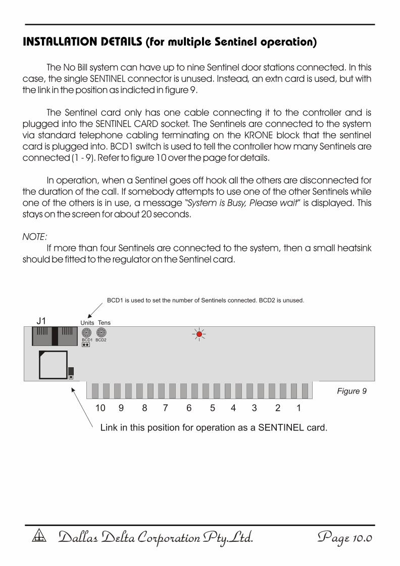
INSTALLATION DETAILS (for multiple Sentinel operation)
The No Bill system can have up to nine Sentinel door stations connected. In this case, the single SENTINEL connector is unused. Instead, an extn card is used, but with the link in the position as indicted in figure 9.
The Sentinel card only has one cable connecting it to the controller and is plugged into the SENTINEL CARD socket. The Sentinels are connected to the system via standard telephone cabling terminating on the KRONE block that the sentinel card is plugged into. BCD1 switch is used to tell the controller how many Sentinels are connected (1 - 9). Refer to figure 10 over the page for details.
In operation, when a Sentinel goes off hook all the others are disconnected for the duration of the call. If somebody attempts to use one of the other Sentinels while one of the others is in use, a message “System is Busy, Please wait” is displayed. This stays on the screen for about 20 seconds.
NOTE:If more than four Sentinels are connected to the system, then a small heatsink
should be fitted to the regulator on the Sentinel card.
10 9 8 7 6 5 4 3 2 1
05123
6 7 8 9
4
Figure 9
05123
6 7 8 9
4
Units Tens
BCD1 BCD2
J1
Link in this position for operation as a SENTINEL card.
BCD1 is used to set the number of Sentinels connected. BCD2 is unused.

Dallas Delta Corporation Pty.Ltd.Dallas Delta Corporation Pty.Ltd. Page 11.0Page 11.0
INSTALLATION DETAILS (for multiple Sentinel operation)
Extn 00
Extn 01
Extn 02
Dallas Delta
Enter Number then #
1 2 3 4 5 6 7 8 9 0
1 2 3 4 5 6 7 8 9 0
1 2 3 4 5 6 7 8 9 0
1 2 3 4 5 6 7 8 9 0
Dallas Delta Corporation Pty. LtdDallas Delta Corporation Pty. Ltd N722
PSTN
SENTINEL
SENTINELCARD
SLAVECARD
-++22Vdc @ 750mA
NO BILL INTERFACE CONTROLLER
VERSION co1.2
Dallas Delta Corporation Pty. LtdDallas Delta Corporation Pty. Ltd N722
Dallas Delta Corporation Pty.Ltd.Dallas Delta Corporation Pty.Ltd.102 Albert St. East Brunswick, 3057 Vic.Tel: 613 93877388 Fax: 613 93873128
Email: [email protected]
N722POWER
PowerSupply
Controller
figure 10
Sentinel 1
LIN
E
PO
WE
R
RE
LA
Y
PowerSupply
Dallas Delta
Enter Number then #
Sentinel 2
LIN
E
PO
WE
R
RE
LA
Y
PowerSupply
SentinelCard
Dallas Delta
Enter Number then #
Sentinel 3
LIN
E
PO
WE
R
RE
LA
Y
PowerSupply
Other Sentinel units (max 9)
Standard telephone cable
Dallas Delta Corporation Pty.Ltd.
Dallas Delta Corporation Pty.Ltd.
102 Albert St. East Brunswick, 3057 Vic.Tel: 613 93877388 Fax: 613 93873128
Email: [email protected]
Manufactures of:
Emergency Lift TelephonesEmergency Telephone SystemsEmergency Services TelephonesIndustrial TelephonesHygienic Environment TelephonesFreeway TelephonesRugged Environment TelephonesHotel Telephones
Prisoner TelephonesPrisoner Phone Monitor SystemsSecurity Door phonesDoor phonesLoud Ringer HornsHigh Voltage Line IsolatorsLoudspeaking Telephones
andthey’re
AllS e n t i n e l N o B i l l v 4.CDR
10/09/2002