Embed Size (px)
Citation preview

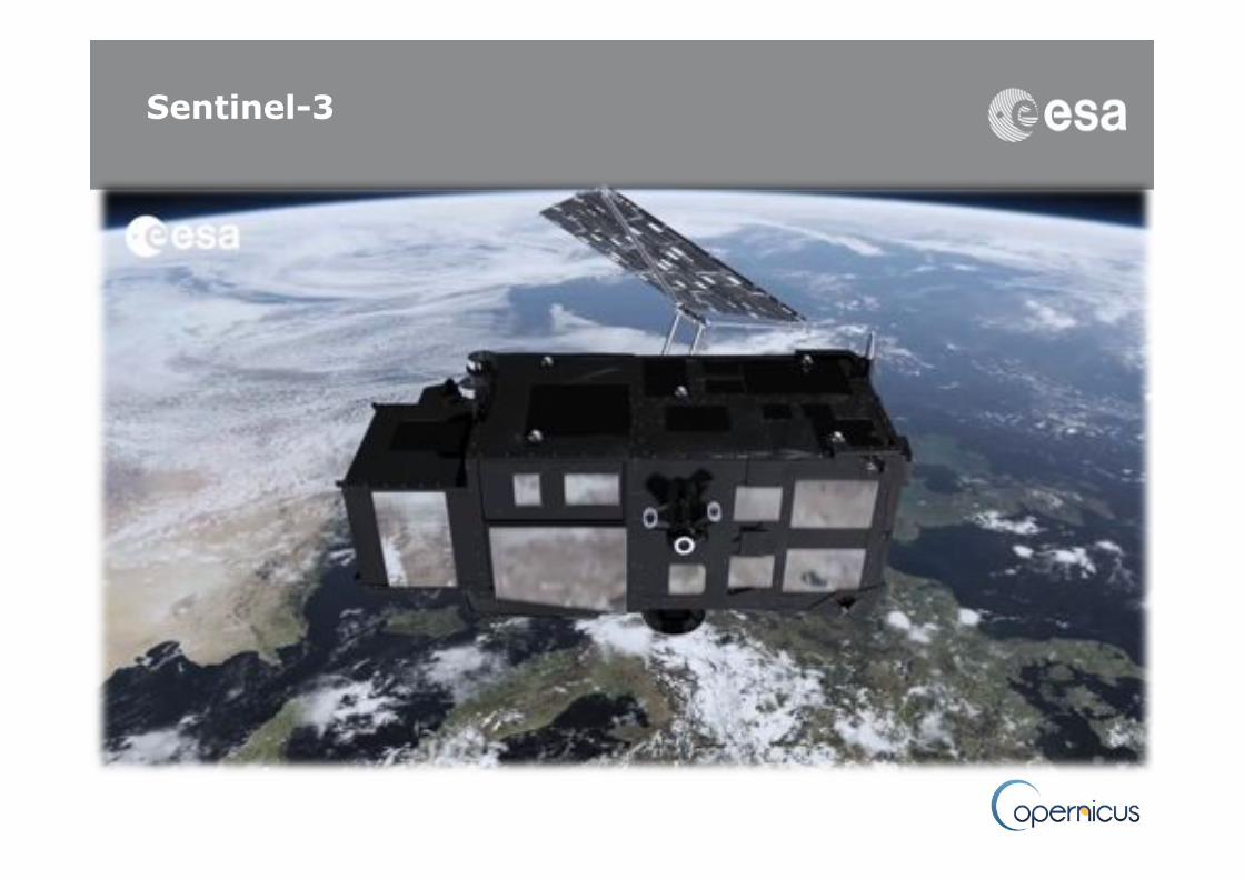
Sentinel-3: Current Status 1 year before Launch
C. Donlon Sentinel-3 Mission Scientist

Overview
• Sentinel-3 Satellite • Sentinel-3 Ground
Segment • Products
• Summary

!Main satellite characteristics!• 1250 kg maximal mass • Volume in 3.89 m x 2.202 m x 2.207 m • Average power consumption of 1100 W • Large cold face for optical instruments thermal control • Modular accommodation for a simplified management of
industrial interfaces • 7.5 years lifetime (fuel for 5 add. Years)
• Launch S3A 2015!• Launch S3B 18 months later !
Observation: • 1 ground contact per orbit • 3h delivery timeliness (from satellite sensing)
Sea and Land Surface
Temperature Radiometer!
Ocean and Land Colour
Instrument!
Microwave !Radiometer!
SAR Radar Altimeter!
X-band Antenna
DORIS Antenna
S-band Antenna
Laser retro-
reflector
GPS
Sentinel-3: The Copernicus Medium Resolution Ocean and Land Mission!
Sentinel-3

GCOS ECV
5
S3 ECV Impact: Atmosphere Impact =6/11 (54%)
✔ T
✔ = S3 capability O = OLCI S = SLSTR T = Topography (MWR, SRAL, POD)
✔ S ✔ OS
✔ OST
✔ OS
✔ OS

6
✔ = S3 capability O = OLCI S = SLSTR T = Topography (MWR, SRAL, POD)
✔ S GCOS ECV & S3:Ocean Impact =5/6 (83%)
✔ ST ✔ T
✔ OST
✔ O
S3 ECV Impact: Ocean

7
✔ OST ✔ OS ✔ OS ✔ OST ✔ OS ✔ OS ✔ O ✔ O
✔ OS ✔ T ✔ S
S3 ECV Impact: Terrestrial Impact =11/12 (92%)
✔ = S3 capability O = OLCI S = SLSTR T = Topography (MWR, SRAL, POD)

Sentinel-3A Satellite Status
• Platform readiness
• Intermediate Satellite Qualification Review successfully completed => Environmental test campaign released • Sentinel-3A AIT progressing: Full satellite and payload integrated since early July
• Payload readiness • SRAL PFM integrated on satellite, tests on-going. • MWR PFM integrated on satellite, no open issues • SLSTR PFM integrated on satellite, tests on-going.
• SLSTR FM2 sub-system tests on-going (LOS, BB), instrument integration plan leads to calibration in Q1 2015. Integration (swap) of FM at satellite level in March 2015. • OLCI PFM integrated on satellite; investigation of thermal issues affecting 1 camera on PFM detected during Tvac tests Camera will be swap for a camera allocated to FM2. • Launch: Current launch window June-Sept 2015, depending on export license clearance from US State Department for launch from Russia • Sentinel-3A predicted FAR Board date is 2nd half of July 2015, resulting in an earliest possible Launch Date 2 months later, 2nd half of September 2015 8
Sent ine l -3A in TAS Cannes test facilities in July 2015 (Credit: TAS)

Sentinel-3B Satellite Status
Sentinel-3B also in TAS Cannes ready for AIT (Credit: TAS)
– Sentinel-3B satellite: Assembly Integration and
Testing (AIT) has started as well with mechanical integration of Topography Payload.
– The platform units are mechanically and electrically integrated.
– SMU recently re-delivered for completing the Platform IST.
– DORIS and LRR are mechanically integrated. – SRAL FM2: is now being integrated into the satellite. – MWR FM2: delivered to TAS and awaiting integration – OLCI-FM2: instrument ready in December 2014. – SLSTR FM1: start of PFM refurbishment no earlier than
March 2015 – Sentinel-3B Final Acceptance Review is predicted at the
end of 2016, corresponding to an earliest Launch date of end 1st quarter 2017.

POD Instruments - status
10
GNSS receiver/antenna integration
Doris receiver mounted on a satellite panel (right) and Doris antenna and LRR (top) mounted on the spacecraft

SRAL: Technical Status
The Sentinel-3A Satellite Thales Alenia Space in Cannes, France, with the Topography Payload installed

Instruments – SRAL status
12
! SRAL PFM development is complete and the instrument is currently under mechanical integration into the spacecraft.
Final functional tests in Toulouse, with antenna provisionally connected in front of
the “RF wall EGSE”
SRAL PFM mechanical integration in the satellite

At SWH = 2m, the altimeter range noise is estimated to 0.7 cm rms. Better than LRM mode since the number of averaged pulses is greater in SAR mode (256 instead of 84 within a tracking cycle)
SRAL calibration and characterisation
• Key parameters to characterize the SRAL altimeter instrument performances are:
• Range Impulse response: • Low Pass Filter: • Range noise
• Some other parameters will require in-flight validation, this will be done during commissioning:
• Antenna pointing accuracy, antenna pattern • Range Absolute bias

14
SRAL Impulse Response
−1000 −500 0 500 1000−50
−45
−40
−35
−30
−25
−20
−15
−10
−5
0
Frequency (kHz)
Nor
mal
ized
leve
l (dB
)
Impulse Response ( Ku−Band ) | mode : SAR I,Q
Side lobe thresholdIdeal side lobesIRIdeal IR
−150 −100 −50 0 50 100 150 200−40
−35
−30
−25
−20
−15
−10
−5
0
Frequency (kHz)
Nor
mal
ized
leve
l (dB
)
Impulse Response ( Ku−Band ) | mode : SAR I,Q
Side lobe thresholdIdeal side lobesIRIdeal IR
Impulse Response function (CAL-1) Ku-band/SAR-mode/Nominal chain
very close to theoretical “sinc” function
C-band Range Impulse Response
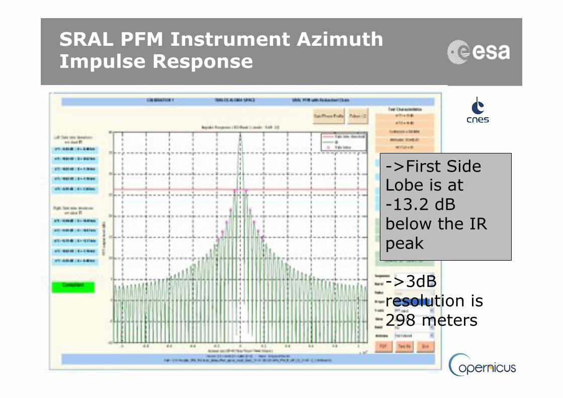
SRAL PFM Instrument Azimuth Impulse Response
->First Side Lobe is at -13.2 dB below the IR peak ->3dB resolution is 298 meters

16
SRAL PFM performance
Receive chain amplitude response (CAL-2)
• No spurious “spikes”
• Ripple within specifications and as expected
0 0.1 0.2 0.3 0.4 0.5 0.6 0.7 0.8 0.9 10
0.1
0.2
0.3
0.4
0.5
0.6
0.7
0.8
0.9
1
−1000 −500 0 500 1000−3.5
−3
−2.5
−2
−1.5
−1
−0.5
0
0.5
1
1.5
Ave
rage
(dB
)
Average, Ku−Band
−1000 −800 −600 −400 −200 0 200 400 600 800 10001
1.05
1.1
1.15
1.2
1.25
1.3
1.35
1.4
1.45
1.5
Zoom
(dB
)
Frequency (kHz)
Average, Ku−Band

SRAL Tracking performance
green: altitude variation of the test scenario red: SRAL PFM tracking window position blue: altitude difference Tracking performance (noise/lag) as expected
0 0.1 0.2 0.3 0.4 0.5 0.6 0.7 0.8 0.9 10
0.1
0.2
0.3
0.4
0.5
0.6
0.7
0.8
0.9
1
0 5 10 15 20 25 30
−250
−200
−150
−100
−50
0
50
100
150
200
m
Time (s)
Altitude variation (Initial altitude : 815042.357 m)
Scenario altitudeAltimeter altitude command
0 5 10 15 20 25 30−16
−15
−14
−13
−12
−11
−10
−9
−8Altitude difference
Time (s)
m
Altitude difference

Instruments – MWR status
18
! MWR PFM test campaign in IABG completed end of August, including mechanical vibrations, thermal vacuum (TB/TV), Instrument performance calibration in vacuum
MWR PFM being prepared for calibration with the installation of
cold loads
MWR PFM & cold loads entering the vacuum chamber

MWR vibration tests
19
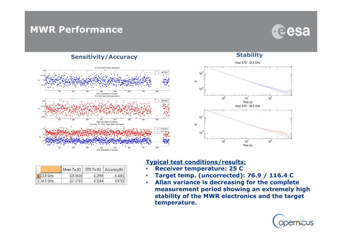
MWR Performance
20
Sensitivity/Accuracy
100 200 300 400 500 600 700 800
115.5
116
116.5
117
Earth observation (I) samples
K
Ta @ 23.8 GHz (Earth observation)
NO BLK
100 200 300 400 500 600 700 800
-1-0.5
00.5
11.5
Earth observation (I) samples
K
Accuracy: Ta - Temp Target (Earth observation)
100 200 300 400 500 600 700 800116.5
117
117.5
118
Earth observation (I) samples
K
Ta @ 36.5 GHz (Earth observation)
NO BLK
23.8 GHz36.5 GHz
100 101 102
10-2
10-1
Allan STD - 23.8 GHz
Time (s)
K
100 101 102
10-2
10-1
Allan STD - 36.5 GHz
Time (s)
K
Typical test conditions/results: • Receiver temperature: 25 C • Target temp. (uncorrected): 76.9 / 116.4 C • Allan variance is decreasing for the complete
measurement period showing an extremely high stability of the MWR electronics and the target temperature.
Stability

Sentinel-3A E1 Commissioning Phase planning
Estimated no earlier than Sept 2015
Estimated no earlier than March 2016
Archive and Offline Processing Centre
Mission Performance Centre (MC)
CDB
CDB
CDB
CDB
CDB
Infoterra UK Farnborough
Indra Madrid
CLS Toulouse
Eumetsat Darmstadt
DLR Oberpfaffenhofen
ACRI Nice
CDB
CLS Brest
CDB
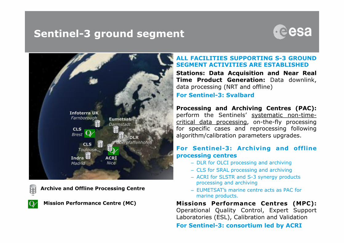
Sentinel-3 ground segment
ALL FACILITIES SUPPORTING S-3 GROUND SEGMENT ACTIVITIES ARE ESTABLISHED Stations: Data Acquisition and Near Real Time Product Generation: Data downlink, data processing (NRT and offline) For Sentinel-3: Svalbard
Processing and Archiving Centres (PAC): perform the Sentinels’ systematic non-time-critical data processing, on-the-fly processing for specific cases and reprocessing following algorithm/calibration parameters upgrades.
For Sentinel-3: Archiving and offline processing centres
– DLR for OLCI processing and archiving – CLS for SRAL processing and archiving – ACRI for SLSTR and S-3 synergy products
processing and archiving – EUMETSAT’s marine centre acts as PAC for
marine products. Missions Performance Centres (MPC): Operational Quality Control, Expert Support Laboratories (ESL), Calibration and Validation For Sentinel-3: consortium led by ACRI

T0 Sensing time
time 3 h 2-3 d ~30 d ~every 1-2 y
NRT products
STC products
NTC products
(only NTC products) Reprocessing Campaign NRT: Near Real time STC: Slow Time Critical NTC: Non time Critical
Ocean forecasting, Meteorology, Oceanography
Operational Ocean, Ocean forecasting, Oceanography
Climatology, Oceanography, Data exploitation
Sentinel-3 Product Timeliness (Example for SRAL)

L 1 FR OL _ 1 _ EFR
L 1 RR
OL _ 1 _ ERR
L 2 FR Land
OL _ 2 _ LFR L 2 FR Water
OL _ 2 _ WFR L 2 RR Land
OL _ 2 _ LRR L 2 RR Water
OL _ 2 _ WRR
L 1 SL _ 1 _ RBT
L 2 Land SL _ 2 _ LST
L 2 Water SL _ 2 _ WST
L 2 VGT _ P
SY _ 2 _ VGP L 2
SYN SY _ 2 _ SYN
L 2 VGT _ S 10 SY _ 2 _ V 10
L 2 VGT _ S 1
SY _ 2 _ VG 1
OLCI PRODUCTS
OLCI & SLSTR SYNERGY PRODUCTS
SLSTR PRODUCTS
VEGETATION - LIKE PRODUCTS
L 2 Marine Products L 2 Land
products L 1 Products
Op#cal'Sensors'Sen#nel.3'User'Products''
Op#cal'Sensor:'Level'2'Products'–'High'Level'''

Original operational baseline: split between LRM and SAR mode Late 2012: Request by the Copernicus user community to extend usage of
SAR mode for the S-3 SRAL instrument up to 100% of Earth coverage.
Low Resolution Mode (LRM) over open ocean
SAR mode over land, sea ice and coastal areas
100% SAR mode
SRAL: Changed observation scenario to 100% SAR
Note: LRM shall be kept as a back-up to reduce operational risks and to allow a possible switch to the LRM scenario if necessary

ESA Presentation | DD/MM/YYYY | Slide 26
ESA UNCLASSIFIED – For Official Use
• BUT: SAR technology is new and complex " Further work required to understand all in-orbit conditions and emerging processing approaches.
• NEW S3 SAR L1A products will be produced and made available to users.
S-3A: First mission to provide 100% SAR altimetry coverage
Product Level
Product Description
Relevance for
L1A Unpacked L0 data processed to engineering parameters with geo-location information
Fundamental studies on SAR processing such as Doppler beam formation and calibration studies using ground-based Transponders
L1B-S Geo-located, Calibrated gathered azimuth formed complex (I and Q) power echoes after slant/Doppler range correction
Geophysical retrieval algorithm developers (over ocean, land and ice surfaces), surface characterisations studies (e.g. impact of sea state bias, wave directional effects etc) and QC systems
L1B Geo-located, Calibrated Multi-looked power waveforms
geophysical retrieval algorithm developers and QC systems
• Expected advantages of L1A: • Foster a new generation of SAR altimetry
specialists maintaining Europe at the competitive edge
• Enhance maintenance and development of existing and new products over the Earth surface (ocean, ice and land) within Copernicus
• Enhance uptake, application, and quality control (e.g. transponder calibration) of SRAL SAR data products by the Copernicus user community
• Reduce large-scale reprocessing efforts (because starting from intermediate L1 products rather than from L0)
SRAL: Changed observation scenario to 100% SAR

Request from EC for two “new” operational products
# Fire Radiative Power – FRP in core product list – FRP at 1 km (pixel level) – Accuracy: goal 10%, threshold 30% – Threshold Detection: Goal 5MW, threshold 50 MW – NRT (< 3 h)
# Aerosol (Global) – Global Aerosol in core product list – Aerosol at pixel level (goal) – Accuracy: goal AOD 0.1 over land, AOD 0.05 over ocean – NRT (< 3 h) – AOD 550 nm over ocean and land (goal) – Include uncertainties at pixel level (goal)
SENTINEL-3: NEW PRODUCTS UNDER DEVELOPMENT FRP and AOD

The Sentinel-3 Mission Performance Centre: Operational Quality Control
Mission Performance Framework
Coordination
External/ complementary
Sentinel-3 Validation
Teams
Expert Support Labora-tories (ESL)
ESA/EUM expertise
Quality Working Groups (QWG)
International Cooperation
ESA/EUM Op. QC
Validation& Analysis
Payload Data
Ground Segment
DB
Potential Sentinel-3 user involvement

October(2014(
CSC'Data'Access:'Interac#on'with'Users'
29(
Collabora#ve'Access'Hub'
Copernicus'Services''Access'
Scien#fic'/'Other'Access'Hub'
Interna#onal'Agreements'Access'Hub'
Copernicus'Space'Component'Data'Access'Portal'
'www.sen&nel.esa.int+
Opening'of'dissemina.on'of'all'S1A'products'to'all'users'on'the'3rd'October'2014'

Data'Access'–'An'Engineering'View'
30(
MSs'Collabora#ve'
Access'
Copernicus'Services''Access''
CSC(GS
(Da
ta(Access(
Scien#fic'/'Other'Access'
Interna#onal'Agreements'
Access'
ESA(funded(R&D(projects(
Scien@fic/(Other((users(
e.g.(scien@fic,(commercial((outreach,(general(public(
Copernicus(Services(
MSs(CollGS(Users(e.g.(public,(scien@fic,(
commercial(
Interna@onal(users(
Funded+and+Operated+by+MSs+
Na@onal(Mirrors(((Inc(local(sta@on)(Na@onal(Mirrors(((Inc(local(sta@on)(
Na#onal'Access''
Interna@onal(Mirrors(Interna@onal(
Mirrors(((Inc(local(sta@on)(
Funded+and+Operated+by++int.+partners++
Int’l Access

Summary
– Sentinel-3A is a mission well-tuned to make a significant contribution to the GCOS ECV
– The S3A Satellite Assembly Integration and Testing (AIT) is proceeding well.
– Launch of the S3A-unit is anticipated in late 2015 – Sentinel-3B satellite is starting integration with a launch
anticipated in 2016/17. – Ground segment development in full development – New L1 products for Altimetry and optical sensors are in
preparation. – The ESA CCI programme is well poised to take full advantage
of early Sentinel-3 data.

Thank you - any questions? For more information http://www.esa.int
See Donlon et al (2012) The GMES Sentinel-3 Mission, Remote Sensing of Environment, http://dx.doi.org/10.1016/j.rse.2011.07.024,
and the Mission Requirements Traceability Document (MRTD) at
http://download.esa.int/docs/EarthObservation/GMES_Sentinel-3_MRTD_Iss-1_Rev-0-issued-signed.pdf
Contact: [email protected]