Embed Size (px)
Citation preview

P.O. Box 7322 ▪ Baltimore, Maryland 21227 ▪ Phone: 410.799.6200 ▪ Fax: 410.799.6416 ▪ website: BaltimoreAircoil.com
July 23, 2008 Sent via email Ms. Kristi Izzo, Secretary New Jersey Board of Public Utilities Two Gateway Center Newark, New Jersey 07102
Re: Written comments regarding New Jersey's Draft Energy Master Plan
Dear Secretary Izzo:
Baltimore Aircoil Company (BAC) applauds the efforts of the BPU, the Governor’s office, and the numerous coordinated agencies to create an Energy Master Plan for the State. We appreciate the opportunity to submit comments for consideration and respectfully request that the BPU consider and include these comments in preparing the final Energy Master Plan.
Baltimore Aircoil Company the worldwide leader in the manufacture and sales of heat transfer and ice thermal storage products that conserve resources and respect the environment. Serving air conditioning, refrigeration, industrial, process, and power generation customers, BAC's product offerings include ice thermal storage systems. As noted in the draft EMP:
“The high price periods generally coincide with the peak periods and accordingly the importance of peak load management. Reduction of the peak load has a direct correlation in reducing the marginal cost of electricity. In addition, peak load reduction can play a major role in reducing harmful environmental emissions. One commonly used measure of performance or efficiency of electricity use is the load factor. Load Factor is calculated as a ratio of the average load to the peak load during the period. The peakier the peak the worse the load factor….”
These issues are the basis on which most thermal storage systems are justified and installed. We respectfully recommend that the final report include incentives for demand shifting technology, and specifically include ice thermal storage as one alternative.
The other key benefit with a fully integrated thermal storage system is that it can reduce overall energy consumption while providing peak load reduction. Attached to the email are two documents, one piece of BAC literature that discuss the overall concept and benefit of ice thermal storage, the second being an ASHRAE (American Society of Heating, Refrigeration and Air Conditioning Engineers) publication that discuss the energy benefits of such systems.
If the regulatory parameters are established to encourage recognized technologies, such as the ice storage systems, to be rapidly implemented in the State, our experience has been that the proponents of such proven technology will seek to become

P.O. Box 7322 ▪ Baltimore, Maryland 21227 ▪ Phone: 410.799.6200 ▪ Fax: 410.799.6416 ▪ website: BaltimoreAircoil.com
active partners as the State moves toward the challenge of meeting its energy goals and legislative mandates. BAC looks forward to offering its experience to commercial customers within New Jersey to help bring a marked reduction to peak energy demands by how the economics and reliability of an ice thermal storage system is truly a “win-win” for the customer and the state.
Please contact me if I can be of service or if you would like to discuss in more detail. Sincerely,
Bill Dietrich Director of Sales and Product Marketing, Commercial and Industrial Products - Americas Baltimore Aircoil Company 410-799-6237 direct [email protected]
Th
erma
l Sto
rag
e Pro
du
ctsICE CHILLER® Thermal Storage Products
F1
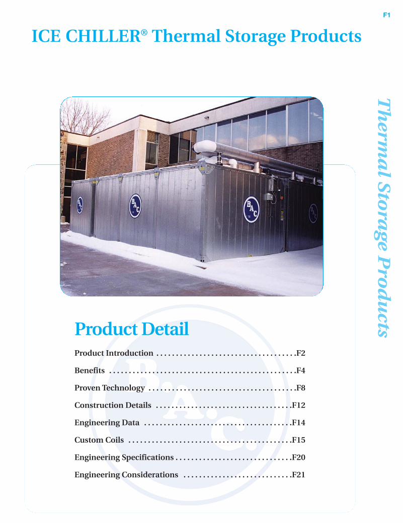
Product DetailProduct Introduction . . . . . . . . . . . . . . . . . . . . . . . . . . . . . . . . . . . .F2
Benefits . . . . . . . . . . . . . . . . . . . . . . . . . . . . . . . . . . . . . . . . . . . . . . . .F4
Proven Technology . . . . . . . . . . . . . . . . . . . . . . . . . . . . . . . . . . . . . .F8
Construction Details . . . . . . . . . . . . . . . . . . . . . . . . . . . . . . . . . . .F12
Engineering Data . . . . . . . . . . . . . . . . . . . . . . . . . . . . . . . . . . . . . .F14
Custom Coils . . . . . . . . . . . . . . . . . . . . . . . . . . . . . . . . . . . . . . . . . .F15
Engineering Specifications . . . . . . . . . . . . . . . . . . . . . . . . . . . . . .F20
Engineering Considerations . . . . . . . . . . . . . . . . . . . . . . . . . . . .F21

ICE
CH
ILL
ER
®F2
Baltimore Aircoil Company
Cooling with ice thermal storage can be the most cost-effective, reliable system approach to cooling offices,
schools, hospitals, malls and other buildings, and provides a steady source of low temperature fluids for
process cooling applications. These systems are environmentally friendly because they help lower energy
consumption and reduce greenhouse gas emissions. With thousands of successful installations worldwide,
BAC is the global leader in the application of ice thermal storage.
Ice Thermal Storage• Lowest first cost
• Reduced energy cost
• Variable capacity
• Improved system reliability
• Reduced maintenance
• Environmentally friendly
• Proven technology
ICE CHILLER® Thermal Storage Products
Th
erma
l Sto
rag
e Pro
du
ctsF3
...because temperature matters™
ICE
CH
ILL
ER
®F4
Baltimore Aircoil Company
Benefits
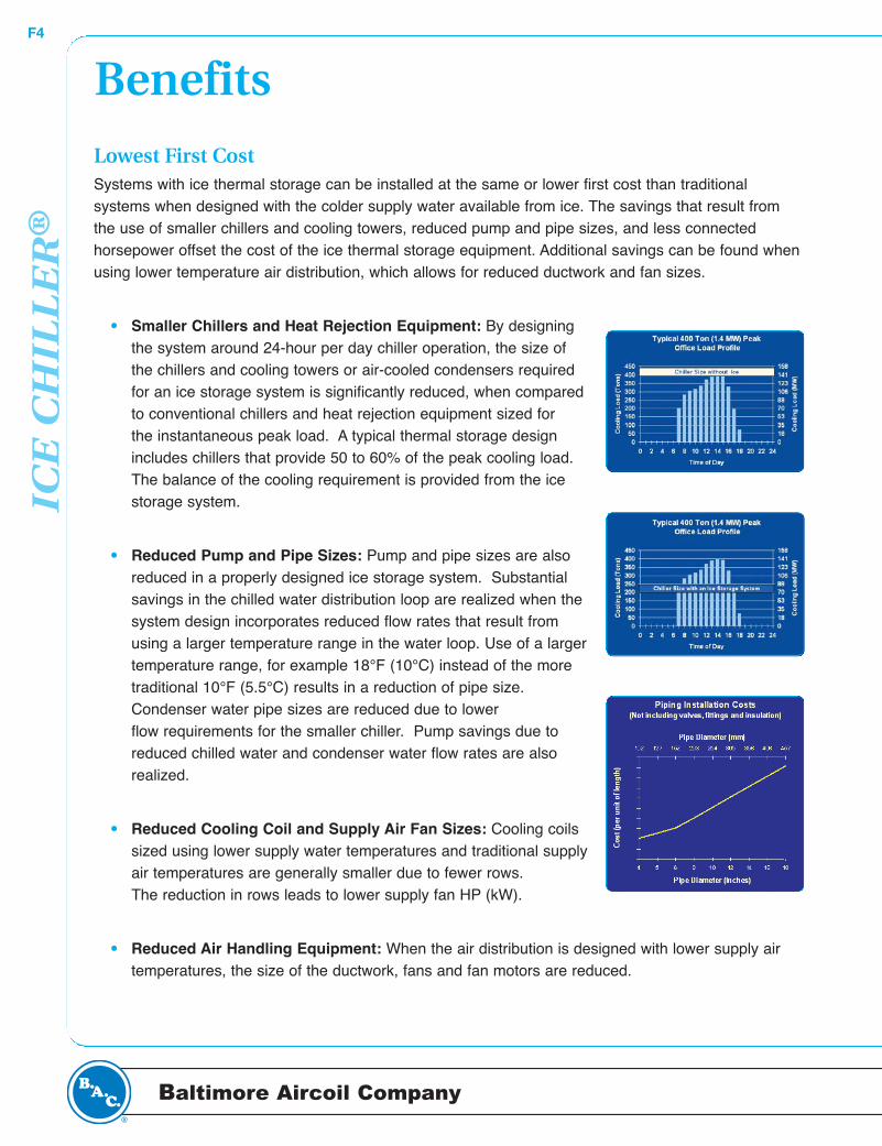
Lowest First Cost Systems with ice thermal storage can be installed at the same or lower first cost than traditional systems when designed with the colder supply water available from ice. The savings that result fromthe use of smaller chillers and cooling towers, reduced pump and pipe sizes, and less connected horsepower offset the cost of the ice thermal storage equipment. Additional savings can be found whenusing lower temperature air distribution, which allows for reduced ductwork and fan sizes.
• Smaller Chillers and Heat Rejection Equipment: By designing the system around 24-hour per day chiller operation, the size of the chillers and cooling towers or air-cooled condensers required for an ice storage system is significantly reduced, when compared to conventional chillers and heat rejection equipment sized for the instantaneous peak load. A typical thermal storage design includes chillers that provide 50 to 60% of the peak cooling load. The balance of the cooling requirement is provided from the ice storage system.
• Reduced Pump and Pipe Sizes: Pump and pipe sizes are also reduced in a properly designed ice storage system. Substantialsavings in the chilled water distribution loop are realized when the system design incorporates reduced flow rates that result from using a larger temperature range in the water loop. Use of a largertemperature range, for example 18°F (10°C) instead of the more traditional 10°F (5.5°C) results in a reduction of pipe size. Condenser water pipe sizes are reduced due to lower flow requirements for the smaller chiller. Pump savings due to reduced chilled water and condenser water flow rates are also realized.
• Reduced Cooling Coil and Supply Air Fan Sizes: Cooling coils sized using lower supply water temperatures and traditional supplyair temperatures are generally smaller due to fewer rows. The reduction in rows leads to lower supply fan HP (kW).
• Reduced Air Handling Equipment: When the air distribution is designed with lower supply air temperatures, the size of the ductwork, fans and fan motors are reduced.
Th
erma
l Sto
rag
e Pro
du
ctsF5
...because temperature matters™
• Reduced Electrical Distribution: Smaller chillers, heat rejection equipment and pumps require less horsepower than a traditional system, which results in smaller transformers, switchgear, wire sizes and starter panels.
• Reduced Generator Size: If a facility has a generator for daily or back-up power, the size of the generator will be significantly reduced when the peak electrical load of the facility is reduced using ice storage.
Reduced Energy CostAn ice thermal storage system reduces peak demand, shifts energy usage to non-peak hours, savesenergy, and reduces energy costs.
• Reduces Peak Demand and Shifts Energy Usage: With less connected horsepower, ice storagecan lower peak electrical demand for the HVAC or process cooling system by 50% or more. Since most electrical rates include demand charges during peak demand times and/or higher day versus night kWh charges, savings on electrical bills can be substantial. Peak electrical demand rates of $15 to $18 per kW are not uncommon. In areas with “real time pricing”, where the electric rate varies hour-by-hour based on the market price of electricity, day to night kWh costs can vary by 500 to 1000%. The use of electricity at night versus peak daytime hours can lead to large savings on energy bills.
• Saves Energy: In addition, total annual kilowatt-hours used are less when the system is designed to take advantage of the low supply water temperature available from ice storage system. Lower kWh consumption is possible for several reasons:
1. Although making ice requires more energy than producing chilled water, the efficiency penalty is not as large since the ice is made at night when condensing temperatures are lower, increasing the efficiency of the chiller.
2. Ice systems typically operate the chiller at full load. Chillers are inefficient when run with low loads during the spring and fall. A conventional chiller will operate at less than 30%
capacity for half the year.
3. Reduced pumping horsepower.
4. Reduced fan horsepower due to lower air pressure drop across the cooling coil. A higher chilled water temperature differential across the cooling coil usually results in fewer rows and therefore a lower pressure drop.
5. The ability to recover waste heat from the chiller for heating water both night and day.
ICE
CH
ILL
ER
®F6
Baltimore Aircoil Company
BenefitsAdditional kWh savings are possible if the air distribution isdesigned to take advantage of the low temperatures available from the ice storage system. As the electric industry continues to deregulate, and time-of-use rates, realtime pricing schedules and negotiated power prices becomestandard, ice storage can provide even greater future savings in operating costs.
Variable CapacityThe ice storage system will maintain a constant supply temperature regardless of the variations in instantaneous cooling demand. The flow and entering water temperature setthe instantaneous capacity.
Improved System ReliabilityIce storage systems provide the reliability necessary to ensureair-conditioning is available. With traditional systems, installing multiple chillers provides redundancy. Inthe event of a mechanical failure of one chiller, the second chiller provides limited cooling capacity. Themaximum available cooling for the traditional system would only be 50% on a design day.
Most ice storage systems utilize two chillers in addition to theice storage equipment. Two chillers are designed to provideapproximately 60% of the required cooling on a design daywhile the ice storage provides the remaining 40% of the cooling capacity. In the event only one chiller is available toprovide cooling during the day, up to 70% of the coolingcapacity is available. The one operable chiller provides 30%of the cooling requirement while the ice provides up to 40%.Based on typical HVAC load profiles and ASHRAE weatherdata, 70% of the cooling capacity would meet the total dailycooling requirements 85% of the time.

Th
erma
l Sto
rag
e Pro
du
ctsF7
...because temperature matters™
Reduced MaintenanceThe ice storage coils have no moving parts, so very little maintenance is required. Because the chillers,pumps and heat rejection equipment are smaller, ice storage systems will have less maintenance thana traditional system. The ice storage system also allows a chiller to undergo routine maintenance duringthe day when the ice storage can handle the system load.
Environmentally FriendlyReducing energy consumption and using electricity at night will reduce global warming. Electricity generated at night generally has a lower heat rate (lower fuel use per power output), and thereforelower carbon dioxide and greenhouse gas emissions resulting in less global warming. The CaliforniaEnergy Commission concluded that the use of electricity at night created a 31% reduction in air emissions over the use of electricity during the day.
With smaller chillers, an ice storage system reduces the amount of refrigerant in a system. Most refrigerants in use today are slated to be banned in the future under the Montreal Protocol because theycontribute to global warming. Using smaller amounts of refrigerant helps to save the ozone layer andreduce global warming.

ICE
CH
ILL
ER
®F8
Baltimore Aircoil Company
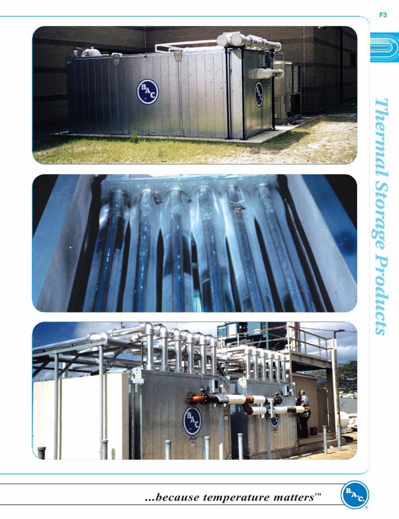
Proven TechnologyBAC has successfully applied ice storage technology to thousands of installations worldwide. BAC hasthe application and system experience to assist in the design, installation and operation of any ice storage system. BAC has supplied ICE CHILLER® Thermal Storage Products for projects that range insize from 90 to 125,000 ton-hours (0.3 to 441.3 MWh). Installations include office buildings, hospitals,manufacturing processes, schools, universities, sports arenas, produce storage facilities, hotels anddistrict cooling applications.
The ICE CHILLER® Product includes a variety of factory-assembled units. For large applications,where space is limited or factory-assembled units are not cost effective, ICE CHILLER® ThermalStorage Coils are available for installation in field-erected tanks.
The BAC product offering provides system design flexibility. Ice can be built using various refrigerantsor glycols on steel coils and is used to provide either chilled water or chilled glycol to the cooling system. This flexibility, combined with a broad range of application experiences, allows BAC to providea cost-effective product to meet your specific requirements.
Merchandise MartMerchandise Mart in Chicago, Illinois installed 26,400 ton-hours (93.2 MWh) of ICE CHILLER® Thermal Storage Coilsin a retrofit of the building’s air-conditioning system. TheMerchandise Mart was built in 1930. The increased air- conditioning load on the building from computers, otherelectrical equipment and increased people density madethe old system too small. Ice thermal storage, with lowtemperature water, allowed the retrofit of the air-conditioning system to go ahead without replacing pipingand ductwork. Increasing the temperature ranges on the piping and air distribution system allowed theMerchandise Mart to install an ice storage system at a lower first cost than a conventional system.
Johns Hopkins Applied Physics LabThe Johns Hopkins University Applied Physics Lab inLaurel, MD installed 5,600 ton-hours (19.8 MWh) of ICECHILLER® Thermal Storage Coils to cool the new StevenMueller Building which houses offices, labs and cleanrooms. Another 2,800 ton-hours (9.9 MWh) of ICECHILLER® Thermal Storage Coils were added to cool adjacent office and lab buildings. The ice thermal storageallows the Applied Physics Lab to save over $150,000 peryear on its electric bill.
Th
erma
l Sto
rag
e Pro
du
ctsF9
...because temperature matters™
Friendship Annex 3 Office BuildingThe HVAC renovation of Friendship Annex (FANX) 2 and3 in Baltimore, MD received the “Outstanding EngineeringAchievement of the Year Award” from the EngineeringSociety of Baltimore. Ice with low temperature air distribution cools these renovated buildings. To meet federal guidelines, a comprehensive study of five alternate systems was made using life cycle costing. Theanalysis showed ice storage with low temperature chilledwater and low temperature air to be the most economical system. A total of 15,230 ton-hours (53.8 MWh)of ICE CHILLER® Thermal Storage Units were installed for the two buildings.
Taipei 101Taipei 101 is located in the central government and business districtof Taipei, Taiwan. The building consists of a podium shopping andentertainment complex and office tower. Completed in August 2002,the 101-floor office tower is the world’s tallest building at 508 meters.
BAC ice storage equipment (36,450 ton-hours) was selected becauseof its ability to provide low fluid temperatures, in this case 36ºF (2°C).Low supply temperatures allowed economical selection of pressureisolation heat exchangers on the 42nd and 74th floors. Additionally, thelow supply temperature allowed cold air distribution to be usedthroughout, thus reducing first costs and operating costs while providing improved occupant comfort.
IMUX Beijing District CoolingIMUX Beijing District Cooling’s first central cooling plant islocated in Beijing’s West Zone Zhongguancun Scienceand Technology Park, China’s largest science parkfocused on developing high-tech enterprises. The plant,largely located underground, incorporates 29,800 ton-hours of BAC ice storage coils in a system whicheffectively uses less expensive nighttime power (75% lessexpensive than daytime power). Chilled water is suppliedat 34ºF (1°C) to a campus-style chilled water distributionloop. Many of the buildings served employ cold air distribution systems to achieve even lower constructionand operating costs.
ICE
CH
ILL
ER
®F10
Baltimore Aircoil Company
Proven Technology
Low Temperature Air
Omni Interlocken ResortHotelThe Omni Interlocken Resort Hotel justoutside of Denver, CO was designedwith a low temperature air and watersystem using ICE CHILLER® ThermalStorage Units. The challenge was todesign a high-quality HVAC systemsensitive to building aesthetics, whichwould provide good guest comfort, lowoperating/maintenance costs and couldbe constructed within a tight construction budget. The first conceptual design was a four-pipe fan-coil system for the hotel rooms with air-cooled chillers and rooftop air-handler units for the publicspaces. The final design was a low temperature air system with Modular ICE CHILLER® ThermalStorage Units. This low temperature air system was $500,000 less than the original conceptualdesign. In addition, the hotel’s energy bills are $100,000 less than with a conventional system.
Villa Julie CollegeModular ICE CHILLER® Thermal Storage Units were part of an expansion that doubled the size of this private college inBaltimore, MD. The new facilities added 135,700 ft2 (12,620 m2)of space to the campus and include a 400-seat auditorium andtheater, gymnasium with showers and locker rooms, student center, video center, academic and computer classrooms, kitchenand administrative offices. The architect designed the new buildings with the intention that the structure be part of the visualspace. This reduced the space allotted for the mechanical equipment. The engineer designed a lowtemperature air system that delivers 45°F (7°C) air temperature to VAV series fan powered boxes. Theuse of smaller piping and ductwork made it possible to avoid architectural changes that would affectthe aesthetics of the design.
Th
erma
l Sto
rag
e Pro
du
ctsF11
...because temperature matters™
Food ProcessingZippy’s Restaurant Central FacilityAt Zippy’s in Honolulu, HI, food is cooked in a centralkitchen where it is cooled and packaged for use in localZippy’s restaurants. The FDA requires that the food in thecooking vessels be cooled to 45°F (7°C) in less than onehour to prevent contamination. The cooking vessels in thekitchen need varying amounts of cooling depending on thedish that is being prepared, and when it finishes its cookingcycle. Because of the varying cooling load from day to dayand hour to hour and the need for a quick cool down period,standard chillers are not a good match for this application. Ice storage with its variable capacity and lowsupply temperature is an excellent match for this process cooling application.
Power GenerationWolverine PowerWolverine Power, located in central Michigan, is a generation and transmission electric cooperative. For a newgenerating plant with (2) 22-megawatt Rolls Royce turbines,Wolverine Power elected to use ice storage for their turbineinlet air cooling. They installed 7,610 ton-hours (26.9 MWH)of ICE CHILLER® Thermal Storage Units to gererate 40°F(4.4°C) chilled water, which provides 55°F (13°C) inlet air.The generating plant’s ice storage capacity can be used over a 16-hour period as partial storage or overa 4-hour period as full storage, depending on the value of power on the open market. During peak summer time, the increased power capacity is worth up to $3,500 per hour in electricity sales.
Emergency CoolingVerizonVerizon, the provider of telephone service to a large portionof the east coast, uses an ICE CHILLER® Thermal StorageUnit to provide back-up cooling to one of its computer centers in Silver Spring, MD. If the chiller that provides cooling goes down for any reason, power outage or alarm,the system immediately switches over to the ice storagesystem for cooling. The pump on the ice storage system ison the continuous power back up with the computers. Thereis enough ice to provide cooling for 30 minutes. This gives Verizon enough time to clear the alarm or getthe back-up generator running and the chiller back on line.
ICE
CH
ILL
ER
®F12
Baltimore Aircoil Company
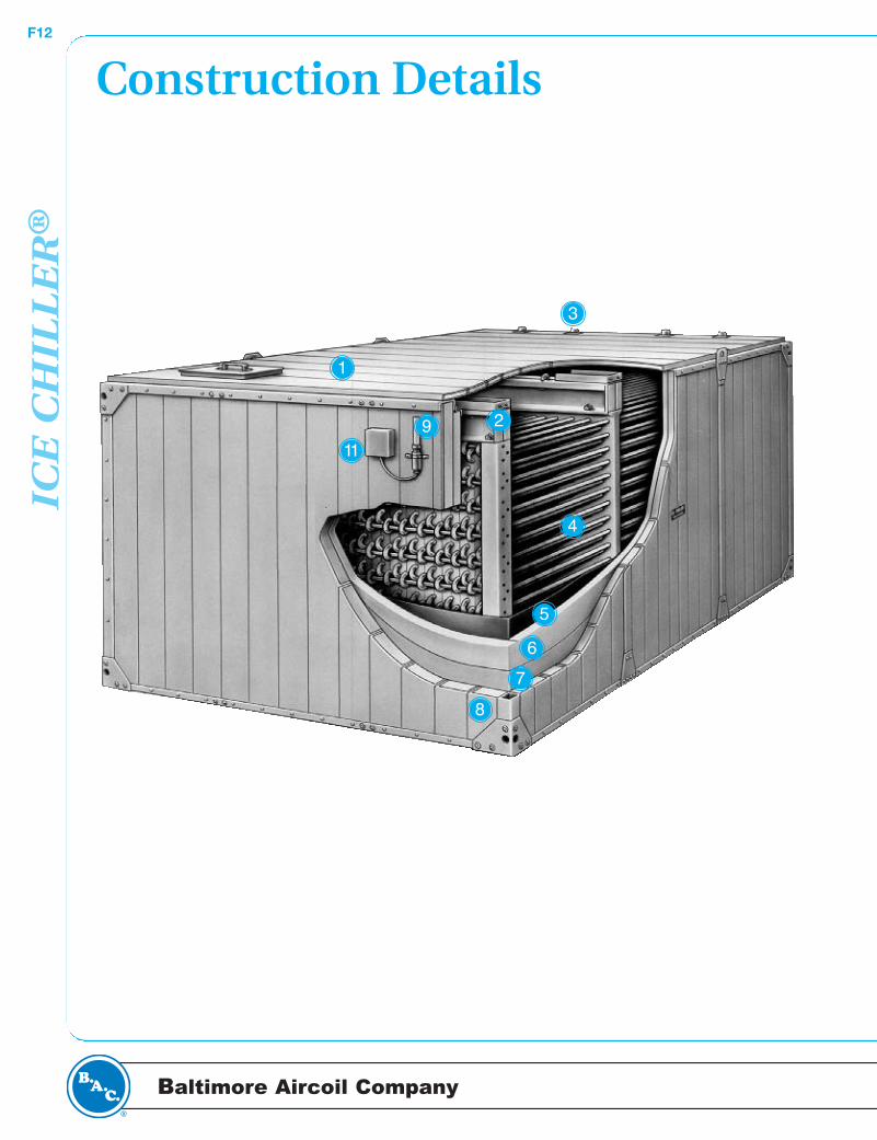
Construction Details
1
2
3
4
5
6
7
8
911
Th
erma
l Sto
rag
e Pro
du
ctsF13
...because temperature matters™
Covers• Watertight
• G-235 (Z700 Metric) Hot-dip galvanized steel panels
• Insulated with 2” expanded polystyrene insulation
Coil Support Beams• Prevent contact between coil and
primary liner
Glycol Connections• Grooved for mechanical coupling
Galvanized Steel Coil• Continuous serpentine, steel tubing
• Hot-dip galvanized after fabrication (HDGAF)
• Pneumatically tested at 190 psig
• Rated for 150 psig operating pressure
Primary Liner• Single piece
• 48-hour integrity test before shipment
Extruded PolystyreneInsulation
• 1.5” thick, installed between primary and secondary liners
Secondary Liner/VaporBarrier
• Prevents moisture from penetrating throughthe insulation
Wall Panel• Heavy-gauge galvanized steel with double
brake flanges
• 3” of expanded polystyrene insulation
Sight Tube• Visual indicator of water level
corresponding to the amount of ice in unit
Operating Control (Not Shown)
• High-level float switch and low water cutoutmounted on the outside of the tank
• Can be provided for one tank (standard) or all tanks (optional)
Ice Inventory Sensor(Optional)
• Differential pressure transmitter provides anelectrical 4-20 mA output signal which is proportional to the amount of ice in inventory
1
2
3
4
5
6
7
8
9
10
11
ICE
CH
ILL
ER
®F14
Baltimore Aircoil Company
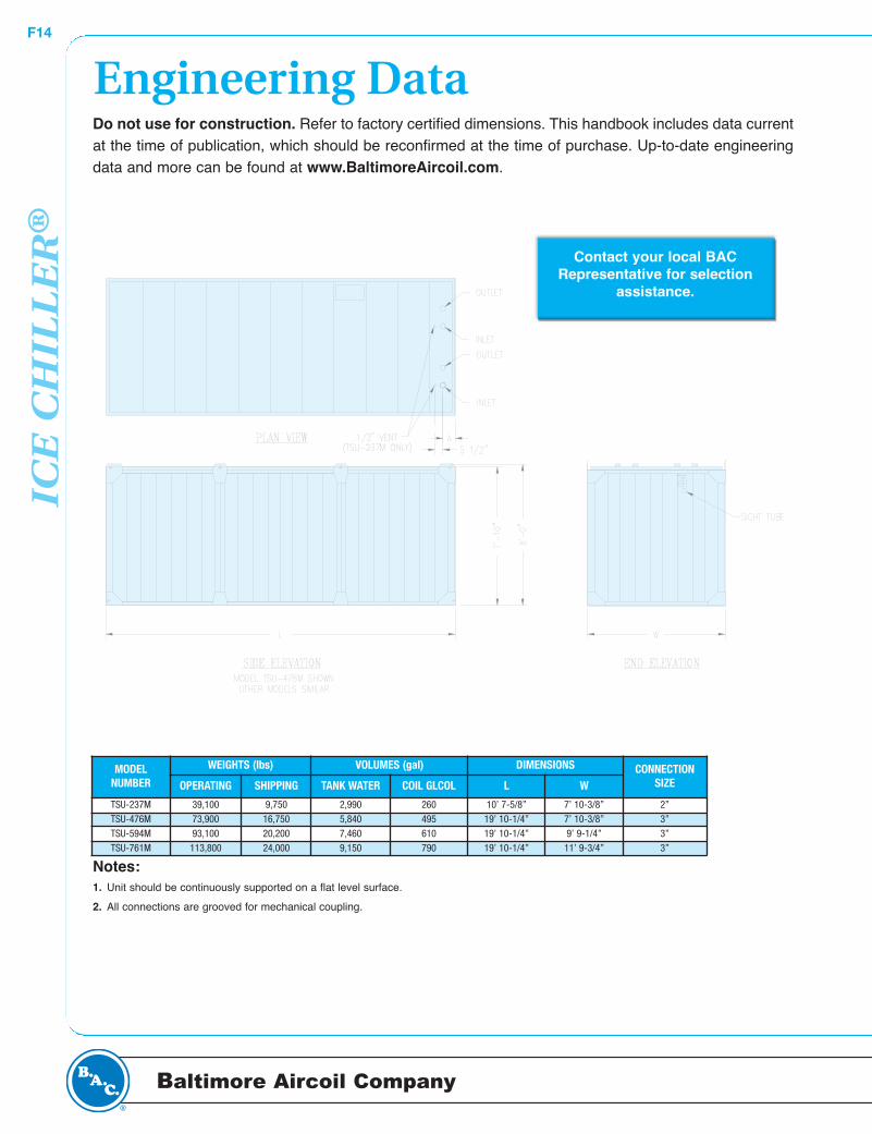
Do not use for construction. Refer to factory certified dimensions. This handbook includes data currentat the time of publication, which should be reconfirmed at the time of purchase. Up-to-date engineeringdata and more can be found at www.BaltimoreAircoil.com.
Engineering Data
Contact your local BACRepresentative for selection
assistance.
PERC
ENT
IC
E B
UIL
D
OVER FLOW
100 %
75 %
50 %
25 %
0 %
Notes: 1. Unit should be continuously supported on a flat level surface.
2. All connections are grooved for mechanical coupling.
MODELNUMBER
WEIGHTS (lbs) VOLUMES (gal) DIMENSIONS CONNECTIONSIZEOPERATING SHIPPING TANK WATER COIL GLCOL L W
TSU-237M 39,100 9,750 2,990 260 10’ 7-5/8” 7’ 10-3/8” 2”TSU-476M 73,900 16,750 5,840 495 19’ 10-1/4” 7’ 10-3/8” 3”TSU-594M 93,100 20,200 7,460 610 19’ 10-1/4” 9’ 9-1/4” 3”TSU-761M 113,800 24,000 9,150 790 19’ 10-1/4” 11’ 9-3/4” 3”

Th
erma
l Sto
rag
e Pro
du
ctsF15
...because temperature matters™
Custom CoilsBAC will manufacture custom ICE CHILLER® Thermal Storage Coils to meet project specific requirements. BAC has done extensive research and testing on the build and melt characteristics of icestorage. This research and testing has resulted in selection capabilities unmatched by any other company in the industry.
BAC can predict the temperatures required on an hour-by-hour basis for building ice on custom coils,over a variety of conditions and build times. The physical space available, load profile, discharge temperatures, chiller capacity and operating sequences can be evaluated to find the design that bestmeets the application.
The ICE CHILLER® Thermal Storage Coils are constructed of continuous 1.05" O.D. all prime surfaceserpentine steel tubing, with no intermediate butt welds. The coils are assembled in a structural steelframe designed to support the weight of the coil stack with a full ice build. After fabrication the coils aretested for leaks using 375 psig air pressure under water, then hot-dip galvanized for corrosion protection.
For glycol applications the coils are configured to provide countercurrent glycol flow in adjacent circuitsfor maximum storage capacity.
Individual coils are factory-assembled into modules of two (2) coils. Glycol manifolds are coated withzinc-rich, cold galvanizing finish at the factory. Necessary support steel and lifting lugs are provided onthe modules to allow for lifting into and final positioning within the storage tank.
Installation of coil module at Oriole Park at Camden Yards, Baltimore, MD

ICE
CH
ILL
ER
®F16
Baltimore Aircoil Company
The modular ICE CHILLER® Thermal Storage Unit can operate in any of five distinct operating modes.These modes of operation provide the flexibility required by building operators to meet their daily HVACcooling requirements.
Ice BuildIn this operating mode, ice is built by circulating a 25% solution (by weight) of inhibited ethylene/propylene glycol through the coils contained in the ICE CHILLER® Thermal Storage Unit. Figure 1 illustrates typical chiller supply temperatures for 8, 10 and 12 hour build cycles. For a typical 10–hourbuild time, the supply glycol temperature is never lower than 22°F (-5.6°C). As the graph illustrates, forbuild times exceeding 10 hours, the minimum glycol temperature is greater than 22°F (-5.6°C). Forbuild times less than 10 hours, the minimum glycol temperature will be lower than 22°F (-5.6°C) at theend of the build cycle. This performance is based on a chiller flow rate associated with a 5°F (2.8°C)range. When a larger temperature range is the basis of the chiller selection, the chiller supply temperatures will be lower than shown in Figure 1.
Engineering Data:Modes of Operation
Figure 1

Th
erma
l Sto
rag
e Pro
du
ctsF17
...because temperature matters™
Ice Build with CoolingWhen cooling loads exist during the ice build period, some of the cold glycol used to build ice is diverted to the cooling load to provide the required cooling. The amount of glycol diverted is determinedby the building loop set point temperature. BAC recommends that this mode of operation be applied onsystems using primary/secondary pumping. This reduces the possibility of damaging the cooling coil orheat exchanger by pumping cold glycol, lower than 32°F (0°C), to this equipment.
Cooling – Ice OnlyIn this operating mode the chiller is off. The warm return glycol solution is cooled to the desired setpoint temperature by melting ice stored in the modular ICE CHILLER® Thermal Storage Unit.
Cooling – Chiller OnlyIn this operating mode the chiller supplies all the building cooling requirements. Glycol flow is divertedaround the thermal storage equipment to allow the cold supply glycol to flow directly to the coolingload. Temperature set points are maintained by the chiller.
Cooling – Ice with ChillerIn this operating mode, cooling is provided by the combined operation of the chiller and ice storageequipment. The glycol chiller precools the warm return glycol. The partially cooled glycol solution thenpasses through the ICE CHILLER® Thermal Storage Unit where it is cooled by the ice to the designtemperature.
Modular ICE Thermal Storage Unit

ICE
CH
ILL
ER
®F18
Baltimore Aircoil Company
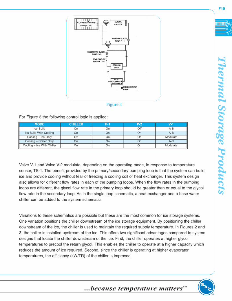
Engineering Data:System Schematics
Two basic flow schematics are applied to selectICE CHILLER® Thermal Storage Units. Figure 2illustrates a single piping loop with the chillerinstalled upstream of the thermal storage equipment. This design allows the thermal storage system to operate in four of the five possible operating modes. They are Ice Build,Cooling-Ice Only, Cooling-Chiller Only andCooling-Ice with Chiller.
For Figure 2 the following control logic is applied:
Valve V-1 modulates in response to temperature sensor, TS-1. Valve V-2 could be positioned to eithermaintain a constant flow, less than P-1, or modulate in response to the return glycol temperature fromthe cooling load.
When the building loop contains chilled water, a heat exchanger must be installed to separate the glycol loop from the building’s chilled water loop. On applications where an existing water chiller isavailable, it can be installed in the chilled water loop to reduce the load on the thermal storage system.
This design should not be used when there is a requirement to build ice and provide cooling. Thiswould require the cold return glycol from the thermal storage equipment be pumped to the cooling loador heat exchanger. Since the glycol temperature is below 32°F (0°C), the cooling coil or heat exchangeris subject to freezing. The flow schematic illustrated in Figure 3 details a primary/secondary pumpingloop with the chiller located upstream of the thermal storage equipment. This design allows the systemto operate in all five operating modes.
Figure 2
MODE CHILLER P-1 V-1 V-2Ice Build On On A-B A-B
Cooling – Ice Only Off On Modulate A-C
Cooling – Chiller Only On On A-C A-C
Cooling – Ice With Chiller On On Modulate A-C
Th
erma
l Sto
rag
e Pro
du
ctsF19
...because temperature matters™
For Figure 3 the following control logic is applied:
Valve V-1 and Valve V-2 modulate, depending on the operating mode, in response to temperature sensor, TS-1. The benefit provided by the primary/secondary pumping loop is that the system can buildice and provide cooling without fear of freezing a cooling coil or heat exchanger. This system designalso allows for different flow rates in each of the pumping loops. When the flow rates in the pumpingloops are different, the glycol flow rate in the primary loop should be greater than or equal to the glycolflow rate in the secondary loop. As in the single loop schematic, a heat exchanger and a base waterchiller can be added to the system schematic.
Variations to these schematics are possible but these are the most common for ice storage systems.One variation positions the chiller downstream of the ice storage equipment. By positioning the chillerdownstream of the ice, the chiller is used to maintain the required supply temperature. In Figures 2 and3, the chiller is installed upstream of the ice. This offers two significant advantages compared to systemdesigns that locate the chiller downstream of the ice. First, the chiller operates at higher glycol temperatures to precool the return glycol. This enables the chiller to operate at a higher capacity whichreduces the amount of ice required. Second, since the chiller is operating at higher evaporator temperatures, the efficiency (kW/TR) of the chiller is improved.
MODE CHILLER P-1 P-2 V-1Ice Build On On Off A-B
Ice Build With Cooling On On On A-B
Cooling – Ice Only Off On On Modulate
Cooling – Chiller Only On On On A-C
Cooling – Ice With Chiller On On On Modulate
Figure 3
ICE
CH
ILL
ER
®F20
Baltimore Aircoil Company
The ICE CHILLER® Thermal Storage Unit(s) shall be BaltimoreAircoil Company Model TSU-______. Each unit shall have alatent ton-hour storage capacity of _______ ton-hours to be generated in ____ hours when supplied with _______ USGPM(lps) of a 25% (by weight) solution of industrially inhibited ethylene/propylene glycol. The minimum glycol temperaturerequired during the ice build operating mode shall be _______°F(°C). Rated system performance shall be provided in the format recommended by the Air-Conditioning & RefrigerationInstitute (ARI) Guideline T. The thermal storage units shall bemodular in design. Unit design shall allow units of different sizesto be installed in order to optimize unit selection and minimizespace requirements. Tanks sizes can be mixed due to internalpiping arrangements that create a balanced flow due to uniformpressure drop through the coil circuits.
The tank shall be constructed of heavy-gauge galvanized steelpanels and include double brake flanges for structural strength.The tank walls shall be supplied with a minimum of 4-1/2" ofinsulation that provides a total insulating value of R-18. The tankdesign shall utilize multiple liners. The primary liner, which formsthe interior of the unit, shall be of single piece construction andbe suitable for low temperature applications. The secondaryliner/vapor barrier shall be separated from the primary liner by1-1/2" of extruded polystyrene insulation. The tank bottom shallbe insulated with 2" of expanded polystyrene insulation and 1" ofextruded polystyrene insulation.
The ICE CHILLER® Thermal Storage Unit shall be provided withwatertight, sectional covers constructed of hot-dip galvanizedsteel. The covers shall be insulated with a minimum of 2" ofexpanded polystyrene insulation.
Contained within the tank shall be a steel heat exchanger that isconstructed of 1.05" O.D., all prime surface serpentine steel tubing encased in a steel framework. The coil, which is hot-dipgalvanized after fabrication, shall be pneumatically tested at 190psig and rated for 150 psig operating pressure. The coil circuitsare configured to provide maximum storage capacity. The coilconnections on the unit are galvanized steel and are grooved formechanical coupling.
Each ICE CHILLER® Thermal Storage Unit shall be provided witha sight tube. The sight tube, which shall be fabricated from clearplastic pipe, shall display the tank water level and correspondingice inventory.
Operating controls, consisting of two float switches, shall bemounted on the outside of the tank. The high level float switchterminates the build cycle when the tank water level reaches the100% ice build level. The high level switch shall also prevent re-initiation of the build cycle until approximately 15% of the icehas been discharged. The second float switch is a low watercutout. The cutout requires that the water level in the ICECHILLER® Thermal Storage Unit be at or above the 0% ice build
level before the ice build cycle can begin. Operating controlquantities vary based on project requirements. An optional differential pressure transmitter shall be available to supply anelectrical output signal proportional to the amount of ice in inventory.
The heat transfer fluid shall be an industrially inhibited, 25% byweight, ethylene/propylene glycol solution specifically designedfor HVAC applications. The 25% (by weight) solution is designedto provide freeze/burst and corrosion protection as well as efficient heat transfer in water based, closed loop systems.Corrosion inhibitors shall be provided to keep pipes free of corrosion without fouling. DOWTHERM® SR-1 andUCARTHERM® are acceptable fluids.
Overall unit dimensions shall not exceed approximately _____ ft(m) by ____ ft (m) with an overall height not exceeding ____ ft(m). The operating weight shall not exceed _______ lbs (kg).
Engineering SpecificationsSee our website at www.BaltimoreAircoil.com for an electronic copy of product engineering specifications.
Th
erma
l Sto
rag
e Pro
du
ctsF21
...because temperature matters™
Engineering Considerations -ICE CHILLER® Thermal Storage ProductsInstallationICE CHILLER® Thermal Storage Units are designed to be installed
outdoors. The units must be installed on a continuous flat level surface.
The pitch of the slab must not exceed 1/8" over a 10’ span. Figure 1
details ICE CHILLER® Thermal Storage Unit layout guidelines. The
units should be positioned so there is sufficient clearance between units
and adjacent walls to allow easy access. When multiple units are
installed, a minimum of 18" is recommended side-to-side and 3'-0"
end-to-end for access to the operating controls.
When installed indoors, the access and slab requirements described
above also apply. The units should be placed close to a floor drain in
the event they need to be drained. The minimum height requirement
above the tank for proper pipe installation is 3 feet. Figure 2 illustrates
the recommended overhead clearance for ICE CHILLER® Thermal
Storage Units.
For large ton–hour applications, BAC will provide ICE CHILLER® Thermal Storage Coils for installation in
field fabricated concrete tanks. When coils are required, BAC’s manufacturing capabilities allow coils to be
manufactured in the size and configuration necessary to meet specific site and performance requirements.
The concrete tank design is to be completed by a qualified structural engineer. Figure 3 illustrates the ICE
CHILLER® Thermal Storage Coil layout guidelines. For large projects that require ICE CHILLER® Coils,
contact your local BAC Representative for selection and dimensional information.
Figure 1
Figure 3Figure 2
ICE
CH
ILL
ER
®F22
Baltimore Aircoil Company
Unit PipingPiping to the ICE CHILLER® Thermal Storage Unit should follow established piping guidelines. The coilconnections on the unit are galvanized steel and are grooved for mechanical coupling.
For single tank applications, each pair of manifoldedcoil connections should include a shut-off valve, sothe unit can be isolated from the system. Figure 4illustrates the valve arrangement for a single unit. It isrecommended that the piping include a bypass circuitto allow operation of the system without the ICECHILLER® Thermal Storage Unit in the piping loop.This bypass can be incorporated into the pipingdesign by installing a three way/modulating valve.This valve can also be used to control the leavingglycol temperature from the thermal storage unit.Temperature and pressure taps should be installed toallow for easier flow balancing and system troubleshooting. A relief valve, set at a maximum of 150 psi, must be installed between the shut-offvalves and the coil connections to protect the coils from excessive pressures due to hydraulic expansion. The relief valve should be vented to a portion of the system which can accommodate expansion.
CAUTION:
The system must include an expansion tank to accommodate changes in fluid volume.Adequately sized air vents must be installed at the high points in the piping loop to removetrapped air from the system.
Figure 5 illustrates reverse return piping for multiple units installed in parallel. The use of reverse returnpiping is recommended to ensure balanced flow toeach unit. Shut-off valves at each unit can be usedas balancing valves.
When large quantities of ICE CHILLER® ThermalStorage Units are installed, the system should bedivided into groups of units. Then, balancing of eachunit can be eliminated and a common balancingvalve for each group of units installed. Shut-off valvesfor isolating individual units should be installed butnot used for balancing glycol flow to the unit.
Figure 4
Figure 5
Th
erma
l Sto
rag
e Pro
du
ctsF23
...because temperature matters™
ControlsTo ensure efficient operation of the ICE CHILLER® Thermal Storage Units, each system is provided with
factory installed Operating Controls. A brief description of the controls follow.
Once the ice build cycle has been initiated, the glycol chiller should run at full capacity without cycling or
unloading until the ICE CHILLER® Thermal Storage Units are fully charged. When the units are fully
charged, the chiller should be turned off and not allowed to re-start until cooling is required. The ice build
cycle is terminated by the Operating Control Assembly. This assembly includes a low water cutout and a
shut-off switch. The low water cutout prevents the ice build mode from starting if there is insufficient water in
the tank. The shut-off switch will terminate the build cycle when the units are fully charged and will prevent
the next ice build mode from starting until 15% of the ice has melted.
Note: Multiple Operating Control Assemblies must be wired in series so that a full build signal from
any one tank will terminate the ice build cyle.
An inventory control that provides a 4 - 20 mA signal is available. This control should be used for
determining the amount of ice in inventory, but not to terminate the ice build cycle. Complete operating
control details are provided in the Installation, Operation and Maintenance Manual.
GlycolICE CHILLER® Thermal Storage Units typically use a 25% (by weight) solution of industrially inhibited
ethylene/propylene glycol for both corrosion protection and freeze protection. Industrial grade inhibited glycol
is specifically designed to prevent corrosion in HVAC and heat transfer equipment. Inhibitors are used to
prevent the ethylene glycol from becoming acidic and to protect the metal components in the thermal
storage system. The system’s lowest operating temperature should be 5°F to 7°F (2.8°C to 3.9°C) above the
glycol freeze point. The freeze point for a system with 25% by weight ethylene glycol is 13°F (10.6°C); the
freeze point for a system with 25% by weight propylene glycol is 15°F (9.4°C).
Acceptable industrial grade inhibited glycol solutions are DOWTHERM® SR–1, DOWFROST® HD and
UCARTHERM®. Use of other brands of glycol in ICE CHILLER® Thermal Storage Products should be
approved by BAC.
DOWTHERM® SR-1, DOWFROST® and UCARTHERM® are registered trademarks of The Dow Chemical Company or its
subsidaries.
CAUTION:
Uninhibited glycol and automotive antifreeze solutions are NOT to be used on thermal storage
applications.

ICE
CH
ILL
ER
®F24
Baltimore Aircoil Company
Water TreatmentIn the near freezing temperatures of the ICE CHILLER® Thermal Storage Unit, scale and corrosion are
naturally minimized. Therefore, water treatment for these two conditions may not be required or may require
minimal attention unless the water is corrosive in nature. To control biological growth, a biocide may be
needed to prevent the spread of iron bacteria or other organisms. For specific recommendations, consult a
reputable local water treatment company and follow the guidelines below:
Note:
1. A water pH of 8.3 or higher will require periodic passivation of the galvanized steel to prevent
“white rust,” the accumulation of white, waxy, nonprotective zinc corrosion products on
galvanized steel surfaces.
To assure full capacity of the ICE CHILLER® Thermal Storage Unit, the water treatment should not alter the
freeze point of water.
Winterization
CAUTION:
Precautions must be taken to protect the unit and associated piping from freezing conditions. Heat
tracing and insulation should be installed on all piping connected to the unit. The sight tube,
operating controls and optional inventory sensor must be protected if the units are installed
outdoors and exposed to sub-freezing ambient conditions.
For this purpose, BAC can provide an optional heated enclosure, complete with a 100 W heater.
Otherwise, the sight tube, operating controls and optional inventory sensor must be heat traced and
insulated. It is not necessary to drain the unit during cold weather.
PROPERTY OF WATER RANGE
pH 7.0 to 9.01
Hardness as CaCO3 30 to 500 ppm
Alkalinity as CaCO3 500 ppm maximum
Total Dissolved Solids 625 ppm maximum
Maximum Conductivity 1000 micromhos/cm @ 32°F
Chlorides 125 ppm maximum as Cl
Sulfates 125 ppm maximum

Th
erma
l Sto
rag
e Pro
du
ctsF25
...because temperature matters™
Pressure DropThe ICE CHILLER® Thermal Storage Unit is designed for low pressure drop. Figure 6 shows the pressure
drop associated with each unit for a 25% solution of industrially inhibited ethylene glycol. Data for flow rates
not shown should not be extrapolated from the performance curve. Pressure drops for flow rates not
presented in this table, and for alternative fluids, are available by contacting the local BAC Representative.
WarrantiesPlease refer to the Limitation of Warranties applicable to and in effect at the time of the sale/purchase of
these products.
Figure 6
NO-94-32-1
ACHiEViNG ENERGY CONSERVATIONWiTH ICE=BASED THERMAL STORAGE
T.W. BradyMember A SHRA E
ABSTRACT
In the last few years, studies have reported that, whilereducing on-peak instantaneous demand for electricalenergy, some existing ice-based thermal storage systemssignificantly increase overall annual energy consumption. Itis thus feared that incentives offered by various electricutility companies to reduce on-peak demamt for electricity,and thereby cost to the customer, will actually increaseelectrical generating requirements and lead to a waste ofnatural resources and increased environmental pollution. Inthis report, actual data collected from buiMings that haveat least two years of operating experience will be used todemonstrate that the negative impacts recognized by thesestudies can be avoided when designers take full advantageof the unique technological features offered by an ice-basedthermal system. Specifically, # will be shown that a thermalstorage system that is fully integrated with the total buiMingdesign will reduce annual energy consumption, reduce peakdemand, reduce annual operating costs, atut reduce theenvironmental impact from the use of mechanical systems.The net impact of thermal storage systems upon the envi-ronment at the generation source will be discussed.
INTRODUCTION
Considerable attention is now being given to therelative annual energy consumption of building heating,ventilating, and air-conditioning (HVAC) systems thatemploy ice-based thermal energy storage (ITES) versusalternati.ve system designs. Reports of the operating resultsachieved by several different ice storage systems (Gillespieand Turnbull 1991) have drawn the criticism of electricutility rate commissions and utility research institutes. Thiscriticism emphasizes the importance of promoting HVACsystem designs that reduce energy consumption, areenvironmentally benign, and, hopefully, reduce energy costto the end-user.
For at least 15 years, ]TES systems have been recog-nized for their ability to shift electric demand from on-peakelectric rate periods to off-peak periods. As a result ofutility rates that charge a high fee for on-peak demandkilowatts (kW), these systems have been able to reduce theoverall cost of electric energy delivered. However, in most
of the cases studied, there has been an increase in theannual energy consumption when compared to theoretically"conventional" HVAC systems. Any increase in energyrequirements is seen as having a negative environmentalimpact due to the greater use of natural resources and theresultant potential for increased carbon dioxide (COz)emissions.
The criticism of ITES systems based upon these allegednegative attributes has led to reduced utility sponsorship ofsystems that utilize this technology and reduced funding forresearch on ITES-related subjects.
It is the author’s experience that ITES systems that areproperly designed to take advantage of all aspects of thetechnology reduce annual energy consumption whencompared to alternative system designs. This paper com-pares system design features as well as annual operatingresults of the selected systems. Factors influencing thesizing and selection of components are discussed, andrecommendations based upon field experience are present-ed. The discussion emphasizes that ITES technology mustbe fully integrated into a building and the HVAC systemdesign in order for all of the benefits to be realized.Further, it shows that comparisons that rank the varioustypes of thermal storage systems in order of energy effi-ciency are not useful for system selection purposes due tothe impact of individual project specifics upon the featuresof each system type.
Following a discussion of the individual systems andassociated energy consumption, the impact of thermalenergy storage (TES) technology on energy use at the pointof generation is investigated. It is the opinion of someresearchers that TES technology increases the off-peak useof coal for electrical generation while reducing the on-peakuse of nuclear energy. It has been assumed that this shift ofprimary fuel will increase CO2 emissions.
The factors that influence the decision of the bulkpower operators as to the most economical mix of generat-ing capacity for any given time are many and vary consid-erably. It is nearly impossible, therefore, to arrive at aconsensus as to whether the widespread use of TES systemswill actually have the assumed negative impact on CO2emissions. From the fact that all utilities attempt to operatetheir most efficient mix of generating capacity at all timesand due to the interconnecting grid that allows neighboring
Thomas W. Brady is president of Brady Consulting Services, Inc., Westchester, IL.
ASHRAE Transactions: Symposia 1735

utilities to sell power to one another, it is reasoned that TEStechnology has a positive effect on CO2 emissions. Thispaper presents that reasoning. Office Area
TABLE 1Building Cooling Load Information
SYSTEM DESIGN COMPARISON
The size of the building under consideration deter-mines, in part, the system configuration options that areavailable to the designer. This statement applies to bothconventional HVAC systems and ITES systems. Theconsiderations presented in this paper apply to buildings thatare 150,000 gross ft 2 (13,935 2) and larger. The specificdesigns that will be analyzed are the HVAC systems thatserve a multi-story office building of 500,000 gross ft2
(46,450 m2). A similar comparison can be drawn forsmaller buildings; however, the type of equipment sdectedfor both the conventional system and the ITES systemwould likely not be the same as that used in this compar-ison.
Coincident peak cooling loadCoincident peak room sensible heat gainMinimum outdoor air required
for ventilation (25 efm/p)
Fitness Center
Cooling load at peakMinimum outside air
Kitchen
Cooling load at peakMinimum outside air
Miscellaneous cooling loads
14,891 MBh9,369 MBh
42,800 cfm
452 MBh5,600 efm
857 MBh20,000 efm
Building Design Considerations
As stated, the building to be analyzed contains 500,000gross ft 2 (46,450 m2), with 412,000 2 (38,275 m2) ofgeneral and private office space that is to be environmental-ly controlled by eight central station air-handling systems.There is also a fitness center and a kitchen that measure18,000 ft 2 (1,672 :) and 9,750 ft2 (906 m2), r espectively.The building is located in a geographical area that has anambient design of 95°F (35°C) dry-bulb (DB) and (24.4°C) wet-bulb (WB).
The local utility has established an on-peak electricaluse period of 9:00 a.m. to 6:00 p.m., Monday throughFriday. All other hours are considered part of the off-peakelectrical period. The charge for electrical consumption (perkWh) during the on-peak period is slightly more than twicethe charge for consumption during off-peak hours. A chargeis levied on the highest instantaneous rate of use (per kW)that is recorded during the on-peak hours in each monthlybilling period. This charge exceeds $16.00 per kW and hasthe effect of making on-peak consumption cost nearly sixtimes more than off-peak consumption.
Pertinent cooling load information on the building isgiven in Table 1. The size of the miscellaneous coolingloads and their location within the building make theirinclusion in the building’s central chilled-water system alogical choice. Thus, combining all cooling loads, the peakdemand on the central system is 17,040 MBh (4,993.7MW).
System Selection
The two central cooling systems selected for compari-son in this analysis are shown in Figures 1 and 2. There isspace for eight air-handling systems that will serve theoffice areas and individual air-handling systems for both thefitness center and the kitchen.
Heat rejection from kitchen refrigeration equipment480 MBh24-hour equipment cooling load 360 MBh
Total Building
Coincident peak cooling loadDaily cooling load on peak day
17,040 MBh187,200 MBh(15,600 ton-h)
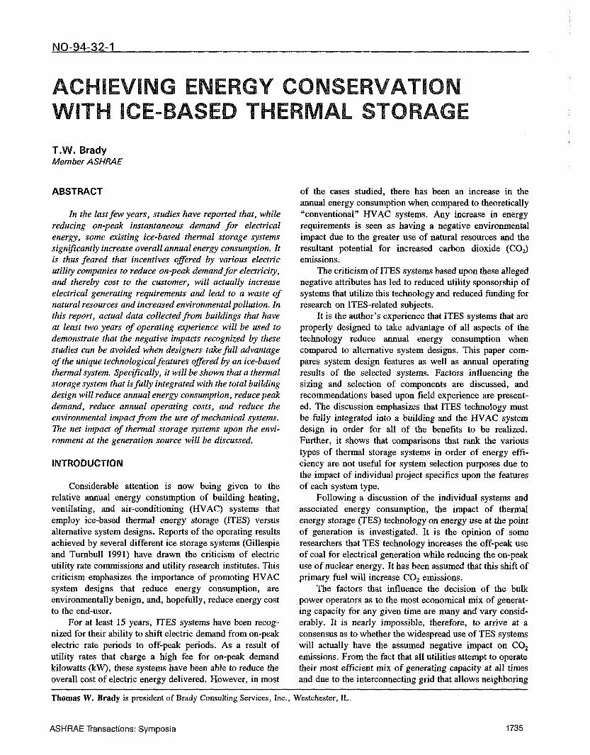
As shown in Figure 1, the conventional system iscomposed of three centrifugal chillers, three cooling towers,individual chiller and condenser water-circulating pumps,and a variable-special primary chilled-water distribution loopto serve the chilled-water coils in the air-handling units andany other uses. "][’here is a heat exchanger that is used inconjunction with one of the cooling towers to provide freecooling to the miscellaneous cooling loads during the wintermonths.
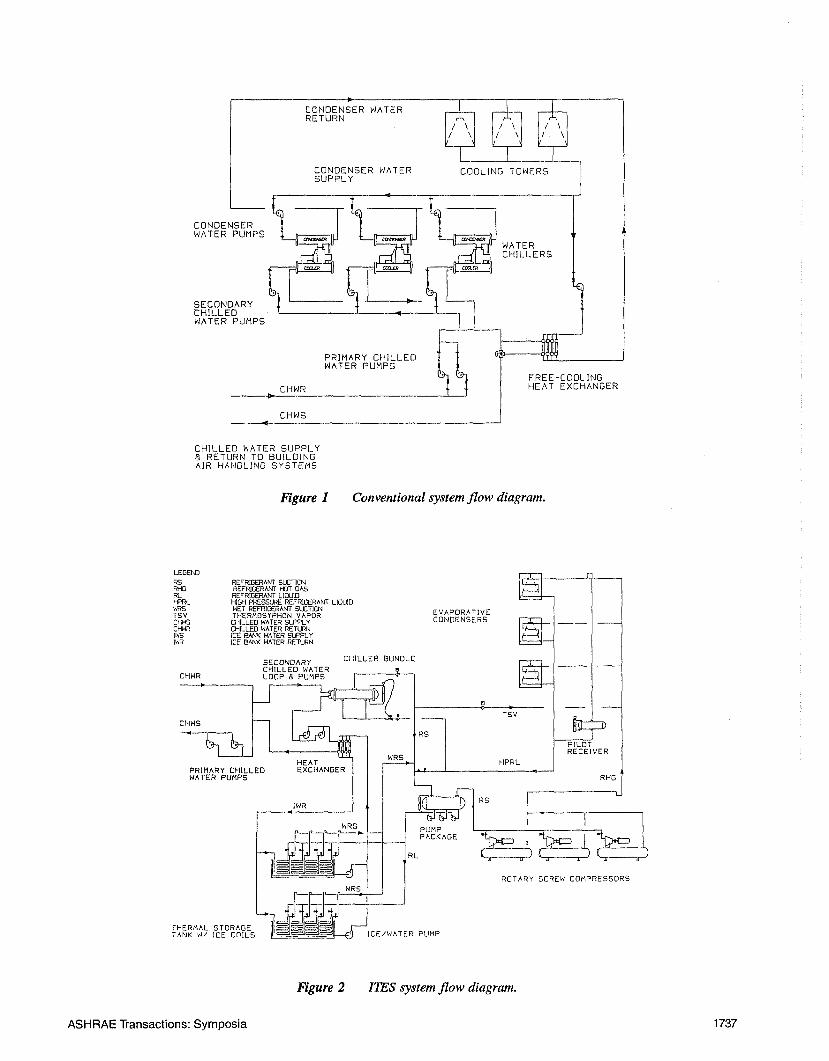
The thermal storage system shown in Figure 2 hasthree rotary screw compressors, three evaporative conden-sers, a liquid overfeed pump/accumulator package, a chillerbundle, an ice-on-coil thermal storage tank, a heat exchang-er between the storage system and the chilled-water system,ice/water pumps, secondary loop pumps, and a variable-speed primary chilled-water distribution loop to serve thechilled-water coils in the air-handling units and any otheruses. In addition to providing compressor-driven waterchilling to supplement the thermal storage in the summermonths, the chiller bundle is used in conjunction with theevaporative condensers to provide thermosiphon cooling tothe miscellaneous cooling loads during the winter months."l’he sumps of the evaporative condensers operate dry duringthis cooling mode.
q’he heating system serving the building is gas hotwater with perimeter heating elements.
1736 ASHRAE Transactions: Symposia
CONDENSER WATERRETURN
CONDENSER WATERSUPPLY
COOLING TOWERS
WATER PUMPS
WATER
CHILLEDSECONDARY WATER PUMPS~~’~ ~iCHILLERS
PRIMARY CHILLEDWATER PUMPS
~ u*~ I FREE-COOLING
~ CHWR ~ ~ HEAT EXCHANGER
CHWS
CHILLED WATER SUPPLYa RETURN TO BUILDINGAIR HANDLING SYSTEMS
Figure I Conventional system flow diagram.
LEGEhORS
RLI-PRL
TSVCHWSC~R
CHWR
CHWS
PRIMARY CHILLEDWATER PUMPS
THERMAL STORAGETANK W/ ICE COILS
REFRIGERANT SUCTIONREFRIGERANT k~DT OASREFRIGERANT LIOUIDI~GH PRESSURE REFRIGERANT LIOUIDWET REFRIGERANT SLETl(24THERMOSYPHON VAPORCHILLED WATER ~LYOHILLED WATER RETURNICE8Al~< WATER SLF~LYICEBANI< WATER RETURN
SECONDARYCHILLED WATERLOOP @ PUMPS
CHILLER BUNDLE
EVAPORATIVECONDENSERS
TSV
HEATEXCHANGER
IWR
WRS PUMP
WRS
--~##~IICE/WATER PUMP
HPRL
PILOTRECEIVER
RHO
ROTARY SCREW COMPRESSORS
Figure 2 ITES system flow diagram.
ASHRAE Transactions: Symposia 1737
Equipment Selection
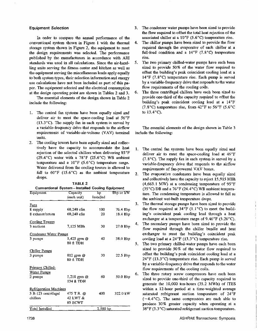
In order to compare the annual performance of theconventional system shown in Figure 1 with the thermalstorage system shown in Figure 2, the equipment to meetthe design requirements was selected. The performancepublished by the manufacturers in accordance with ARIstandards was used in all calculations. Since the air-hand-ling units serving the fitness center and kitchen as well asthe equipment serving the miscellaneous loads apply equallyto both syste~n types, their selection information and energyuse calculations have not been included as part of this pa-per. The equipment selected and the electrical consumptionat the design operating point are shown in Tables 2 and 3.
The essential elements of the design shown in Table 2include the following:
Equipment
The central fan systems have been equally sized anddeliver air to meet the space-cooling load at 56°F(13.3°C). The supply fan in each system is served a variable-frequency drive that responds to the airflowrequirements of variable-air-volume (VAV) terminalunits.The cooling towers have been equally sized and collec-tively have the capacity to accommodate the heatrejection of the selected chillers when delivering 85°F(29.4°C) water with a 78°F (25.6°C) WB ambienttemperature and a 10°F (5.6°C) temperature range.Water delivered from the cooling towers is allowed tofall to 60°F (15.6°C) as the ambient temperaturedrops.
TABLE 2Conventional System--Installed Cooling Equipment
Capacity hp Bhp or kW(each unit) Installed
Fan_...__qs8 supply 60,240 cfm 100 76.4 Bhp8 exhaust/return 60,240 cfm 20 18.4 Bhp
Cooling Towers3 sections 7,125 MBh 30 27.0 Bhp
Condenser Water Pumps3 pumps 1,425 gpm @
80 ft TDH40 38.0 Bhp
Chiller Pumps3 pumps 812 gpm @ 30 22.5 Bhp
80 ft TDH
Primary Chilled-Water Pumos2 pumps 1,218 gpm @ 60 50.0 Bhp
134 ft TDH
Refrigeration Machines3 R-123 centrifugalchillers
475 T.R. @42 LWT &85 ECWT
400 322.0 kW
Total Installed 2,580 hp
3. The condenser water pumps have been sized to providethe flow required to offset the total heat rejection of theassociated chiller at a 10°F (5.6°C) temperature rise.
4. The chiller pumps have been sized to provide the flowrequired through the evaporator of each chiller at afull-load condition and a 14°F (7.8°C) temperaturerise.
5. The two primary chilled-water pumps have each beensized to provide 50% of the water flow required tooffset the building’s peak coincident cooling load at a14°F (7.8°C) temperature rise. Each pump is servedby a variable-frequency drive that responds to the waterflow requirements of the cooling coils.
6. The three centrifugal chillers have each been sized toprovide one-third of the capacity required to offset thebuilding’s peak coincident cooling load at a 14°F(7.8°C) temperature rise, from 42°F to 56°F (5.6°Cto 13.4°C).
The essential elements of the design shown in Table 3include the following:
1. The central fan systems have been equally sized anddeliver air to meet the space-cooling load at 46°F(7.8°C). The supply fan in each systeru is served by variable-frequency drive that responds to the airflowrequirements of fan-powered VAV boxes.
2. The evaporative condensers have been equally sizedand collectively have the capacity to reject 15,915 MBh(4,663.1 MW) at a condensing temperature of 95°F(35°C) DB and a 76°F (24.4°C) WB ambient tempera-ture. The condensing temperature is allowed to fall asthe ambient wet-bulb temperature drops.
3. The thermal storage pumps have been sized to providethe flow required at 34°F (1.1°C) to meet the build-ing’s coincident peak cooling load through a heatexchanger at a temperature range of 9.46°F (5.26°C).
4. The secondary pumps have been sized to provide theflow required through the chiller bundle and heatexchanger to meet the building’s coincident peakcooling load at a 24°F (13.3°C) temperature rise.
5. The two primary chilled-water pumps have each beensized to provide 50% of the water flow required tooffset the building’s peak coincident cooling load at a24°F (13.3°C) temperature rise. Each pump is servedby a variable-frequency drive that responds to the waterflow requirements of the cooling coils.
6. The three rotary screw compressors have each beensized to provide one-third of the capacity required togenerate the 10,000 ton-hours (35.2 MWh) of ITESwithin a 12-hour period at a time-weighted averagesaturated refrigerant suction temperature of 24°F(-4.4°C). The same compressors are each able produce 30% greater capacity when operating at a38 OF (3.3 ° C) saturated refrigerant suction temperature.
1738 ASHRAE Transactions: Symposia
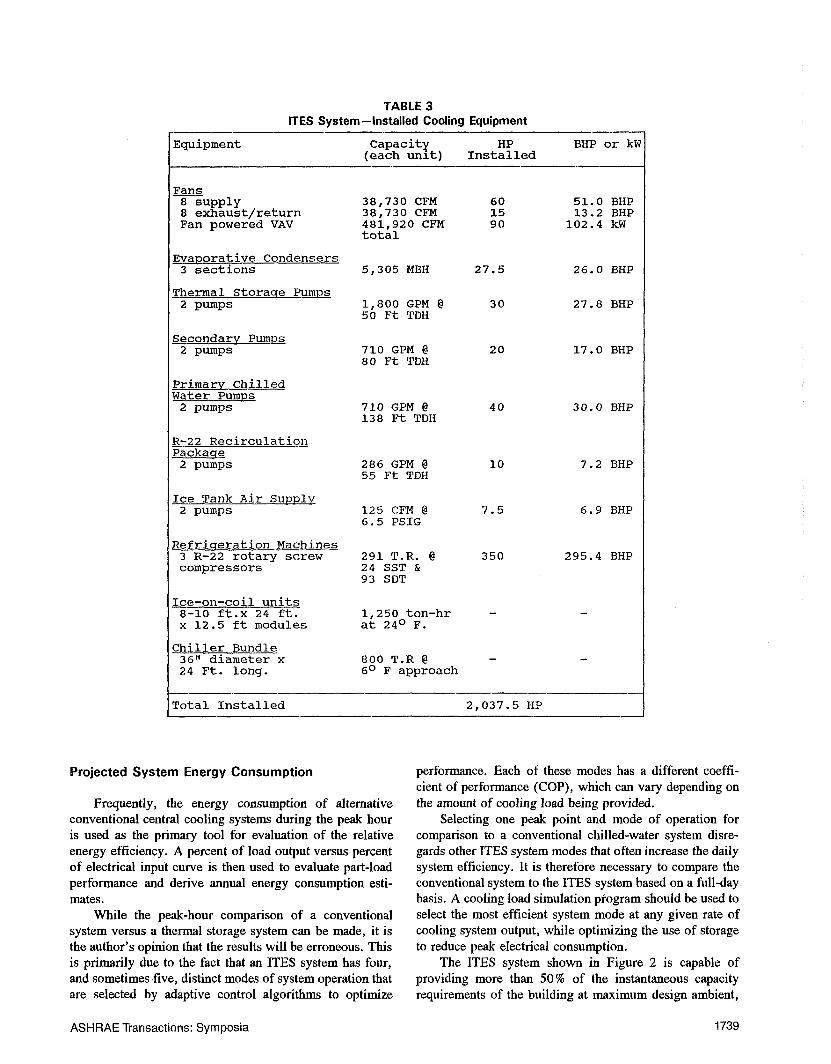
TABLE 3ITES System--Installed Cooling Equipment
Equipment Capacity HP BHP or kW(each unlt) Installed
Fans8 supply 38,730 CFM 60 51.0 BHP8 exhaust/return 38,730 CFM 15 13.2 BHPFan powered VAV 481,920 CFM 90 102.4 kW
total
~aporative Condensers3 sections 5,305 MBH 27.5 26.0 BHP
~hermal.......Storage Pumps2 p~mps 1,800 GPM @ 30 27.8 BHP
50 Ft TDH
Secondary pump__s2 pumps 710 GPM @ 20 17.0 BHP
80 Ft TDH
PrimarvChilledWater Pumps
2 pumps
R-22 Recirculation
710 GPM @ 40 30.0 BHP138 Ft TDH
Packaqe2 pumps 286 GPM @ I0 7.2 BHP
55 Ft TDH
Ice Tank Air Supply2 pumps 125 CFM @ 7.5 6.9 BHP
6.5 PSIG
Refriqeration Machines3 R-22 rotary screwcompressors
Ice-on-coil units8-10 ft.x 24 ft.x 12.5 ft modules
Chiller Bundle36" diameter x24 Ft. long.
291 T.R. @24 SST &93 SDT
1,250 ton-hrat 24° F.
800 T.R @6° F approach
350 295.4 BHP
Total Installed 2,037.5 HP
Projected System Energy Consumption
Frequently, the energy consumption of alternativeconventional central cooling systems during the peak houris used as the primary tool for evaluation of the relativeenergy efficiency. A percent of load output versus percentof electrical input curve is then used to evaluate part-loadperformance and derive annual energy consumption esti-
mates.While the peak-hour comparison of a conventional
system versus a thermal storage system can be made, it isthe author’s opinion that the results will be erroneous. Thisis primarily due to the fact that an ITES system has four,and sometimes five, distinct modes of system operation thatare selected by adaptive control algorithms to optimize
performance. Each of these modes has a different coeffi-cient of performance (COP), which can vary depending the amount of cooling load being provided.
Selecting one peak point and mode of operation forcomparison to a conventional chilled-water system disre-gards other ITES system modes that often increase the dailysystem efficiency. It is therefore necessary to compare theconventional system to the ITES system based on a full-daybasis. A cooling load simulation program should be used toselect the most efficient system mode at any given rate ofcooling system output, while optimizing the use of storageto reduce peak electrical consumption.
The ITES system shown in Figure 2 is capable ofproviding more than 50% of the instantaneous capacityrequirements of the building at maximum design ambient,
ASHRAE Transactions: Symposia 1739
with a compressor COP of 6.17. This is accomplished byoperating two of the three compressors at full load toprecool the return water prior to the ice/water heat ex-changer. "l~ne chiller bundle that provides the heat transfersurface is sized to provide a close approach temperature,resulting in a refrigerant evaporating temperature of no lessthan 40°F (4.4°C) at peak load. Further, the saturatedrefrigerant discharge temperature at the compressor is heldwithin 12°F (6.7°C) of the ambient wet-bulb temperaturedue to the fact that two compressors are operating on thefull condensing surface that serves three compressors in theice-building mode of operation. These factors combine toyield a low compression ratio of 2.28:1. The efficiency ofthe compressors during a water-chilling mode improvesfurther at times when only one compressor operates on thefull evaporating and condensing surfaces. Thus, part-loadoperation in an ITES system does not necessarily meanreduced efficiency. It is important to note that the locationof the chiller relative to the thermal storage makes thiscompressor operation efficient. If the chiller was located onthe leaving side of the thermal storage, then it would haveto provide the 36°F (2.2°C) design chilled-water supplytemperature. This location would reduce the compres-sor/chiller efficiency due to having to maintain a lowerevaporator temperature and higher compression ratio.
Another beneficial feature of the system shown inFigure 2 is that the pumping horsepower is reduced com-
pared to the requirements shown for Figure 1. This isprimarily the result of designing the system for a 24°F(13.3 °C) temperature range, with the supply water held 36°F (2.2°C). Also, the condenser water pumps that areneeded in the conventional system consume 35% moreelectrical power than all other pumps required in the ITESsystem.
Certainly a key ingredient to the overall efficiency ofthe ITES system lies in the comparison of the energyrequirements for the building’s air-moving apparatus tothose same requirements in a conventional system. Atmaximum air delivery, the fans in the ITES design consumenearly 28% less electrical energy than the fans in theconventional system. This is due to the use of 36°F (2.2°C)water available from the ITES central system to generatesupply air that has a 24 % lower heat content than the airdelivered from conventional systems. The supply fans inboth systems are controlled by variable-frequency drivesand, as a result, the percentage of energy savings remainsrelatively constant throughout all annual operating hours.
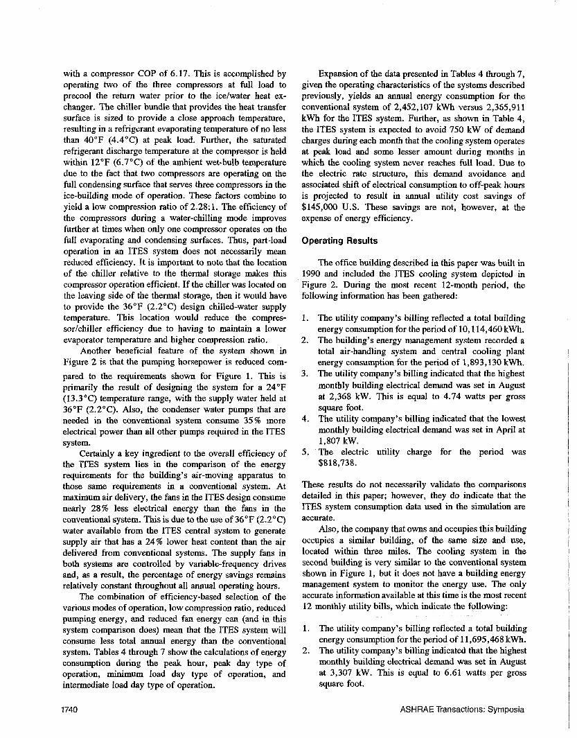
The combination of efficiency-based selection of thevarious modes of operation, low compression ratio, reducedpumping energy, and reduced fan energy can (and in thissystem comparison does) mean that the ITES system willconsume less total annual energy than the conventionalsystem. Tables 4 through 7 show the calculations of energyconsumption during the peak hour, peak day type ofoperation, minimum load day type of operation, andintermediate load day type of operation.
Expansion of the data presented in Tables 4 through 7,given the operating characteristics of the systems describedpreviously, yields an annual energy consumption for theconventional system of 2,452,107 kWh versus 2,365,911kWh for the ITES system. Further, as shown in Table 4,the ITES system is expected to avoid 750 kW of demandcharges during each month that the cooling system operatesat peak load and some lesser amount during months inwhich the cooling system never reaches full load. Due tothe electric rate structure, this demand avoidance andassociated shift of electrical consumption to off-peak hoursis projected to result in annual utility cost savings of$145,000 U.S. These savings are not, however, at theexpense of energy efficiency.
Operating Results
The office building described in this paper was built in1990 and included the ITES cooling system depicted inFigure 2. During the most recent 12-month period, thefollowing information has been gathered:
1. The utility company’s billing reflected a total buildingenergy consumption for the period of 10,114,460 kWh.
2. The building’s energy management system recorded atotal air-handling system and central cooling plantenergy consumption for the period of 1,893,130 kWh.
3. The utility company’s billing indicated that the highestmonthly building electrical demand was set in Augustat 2,368 kW. This is equal to 4.74 watts per grosssquare foot.
4. The utility company’s billing indicated that the lowestmonthly building electrical demand was set in April at1,807 kW.
5. ’The electric utility charge for the period was$818,738.
These results do not necessarily validate the comparisonsdetailed in this paper; however, they do indicate that theITES system consumption data used in the simulation areaccurate.
Also, the company that owns and occupies this buildingoccupies a similar building, of the same size and use,located within three miles. The cooling system in thesecond building is very similar to the conventional systemshown in Figure 1, but it does not have a building energymanagement system to monitor the energy use. "rhe onlyaccurate information available at this time is the most recent12 monthly utility bills, which indicate the following:
1. The utility company’s billing reflected a total buildingenergy consumption for the period of 11,695,468 kWh.
2. The utility company’s billing indicated that the highestmonthly building electrical demand was set in Augustat 3,307 kW. This is equal to 6.61 watts per grosssquare foot.
1740 ASHRAE Transactions: Symposia
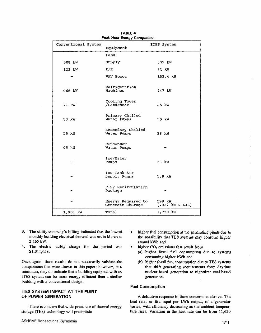
TABLE 4Peak Hour Energy Comparison
Conventional System ITES SystemEquipment
508 kW
122 kW
966 kW
71 kW
83 kW
56 kW
95 kW
Fans
Supply 339 kW
E/R 91 kW
VAV Boxes 102.4 kW
RefrigerationMachines 447 kW
Cooling Tower/Condenser 65 kW
Primary ChilledWater Pumps 50 kW
Secondary ChilledWater Pumps 28 kW
CondenserWater Pumps -
Ice/WaterPumps 23 kW
Ice Tank AirSupply ~imps 5.8 kW
R-22 RecirculationPackage -
Energy Required to 599 kWGenerate Storage (.927 kW x 646)
1,901 kW Total 1,750 kW
3. The utility company’s billing indicated that the lowestmonthly building electrical demand was set in March at2,165 kW.
4. The electric utility charge for the period was$1,011,658.
Once again, these results do not necessarily validate thecomparisons that were drawn in this paper; however, at a
minimum, they do indicate that a building equipped with anITES system can be more energy efficient than a similarbuilding with a conventional design.
ITES SYSTEM IMPACT AT THE POINTOF POWER GENERATION
There is concern that widespread use of thermal energystorage (TES) technology will precipitate
higher fuel consumption at the generating plants due tothe possibility that TES systems may consume higherannual kWh andhigher CO2 emissions that result from(a) higher fossil fuel consumption due to systems
consuming higher kWh and(b) higher fossil fuel consumption due to TES systems
that shift generating requirements from daytimenuclear-based generation to nighttime coal-basedgeneration.
Fuel Consumption
A definitive response to these concerns is elusive. Theheat rate, or Btu input per kWh output, of a generatorvaries, with efficiency decreasing as the ambient tempera-ture rises. Variation in the heat rate can be from 11,630
ASHRAE Transactions: Symposia 1741
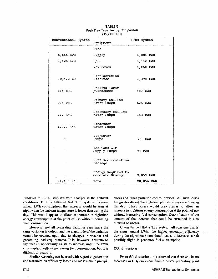
TABLE 5Peak Day Type Energy Comparison
(15,000 T-H)
Conventional System ITES SystemEquipment
Fans
5,855 kWH Supply 4,084 kWH
1,525 kWH E/R 1,132 kWH
- VAV Boxes 1,280 kWH
Refrigeration10,420 kWH Machines 3,398 kWH
Cooling Tower884 kWH /Condenser 487 kWH
Primary Chilled981 kwh Water Pumps 625 kWH
Secondary Chilled662 kWH Water Pumps 353 kWH
Condenser1,079 kWH Water Pumps -
Ice/Water- Pumps 371 kWH
Ice Tank Air- Supply Pumps 93 kwh
R-22 Recirculation- Package -
Energy Required to- Generate Storage 9,033 kWH
21,406 kWH Total 20,856 kWH
Btu/kWh to 7,700 Btu/kWh with changes in the ambientconditions. If it is assumed that TES systems increaseannual kWh consumption, that increase would be seen atnight when the ambient temperature is lower than during theday. This would appear to allow an increase in nighttimeenergy consumption at the point of use without increasingfuel consumption.
However, not all generating facilities experience thesame variation in output, and the magnitude of the variationc~ot be counted upon due to changes in weather andgenerating load requirements. It is, however, accurate tosay that an opportunity exists to increase nighttime kWhconsumption without increasing fuel consumption, but it isdifficult to quantify.
Similar reasoning can be used with regard to generationand transmission efficiency losses and losses due to precipi-
tators and other pollution control devices. All such lossesare greater during the high-load periods experienced duringthe day. These losses would also appear to allow anincrease in nighttime energy consumption at the point of usewithout increasing fuel consumption. Quantification of the
amount of the increase that could be sustained is alsodifficult to obtain.
Given the fact that a TES system will consume nearlythe same annual kWh, the higher generato r efficiencyduring the nighttime hours should cause a decrease, albeitpossibly slight, in generator fuel consumption.
CO2 Emissions
From this discussion, it is assumed that there will be noincreases in CO2 emissions from a power-generating plant
1742 ASH RAE Transactions: Syrnposia
TABLE 6Intermediate Day Type Energy Comparison
(9,000 T-H}
Conventional System ITES SystemEquipment
Fans
4,572 kWH Supply 3,053 kWH
1,464 kWH E/R 1,087 kWH
- VAV Boxes 1,280 kWH
Refrigeration5,769 kwh Machines -
Cooling Tower564 kwh /Condenser -
Primary Chilled744 kWH Water Pumps 450 kWH
Secondary Chilled481 kWH Water Pumps 228 kWH
Condenser768 kWH Water Pumps -
Ice/Water- Pumps 276 kWH
Ice Tank Air- Supply Pumps 70 kWH
R-22 Recirculation- Package -
Energy Re.fired to- Generate Storage 7,515 kWH
14,362 kWH Total 13,959 kWH
resulting from increased fuel consumption attributed to TEStechnology.
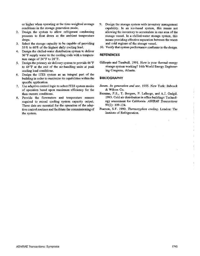
Concerns of increased fossil fuel use relative to the useof nuclear fuel do not appear to be well founded. The mixof fuels used at any point on the generation curve variesfrom one utility to the next. Also, not all utilities have anuclear base and therefore rely on the fossil fuels of coal,gas, and oil. Figure 3 depicts a 24-hour power generationcurve for a utility that uses all four fuels.
It can be seen from the curve that any nighttimeincrease in generation will be met by loading up the nuclearcapacity. The philosophy of the operators is to attempt to
use the mix of fuels with the lowest cost for any given day.With the relative costs for fuel being $5.60/MW, nuclear;$9.50 to $11.00/MW, coal; $15.00/MW, gas; and $30.00,
oil, any additional capacity requirement, whenever itoccurs, will be met with nuclear generation if it is avail-able.
The opposite side of the consideration is whether a
decrease in the daytime generation requirement will be metwith a reduction in nuclear fuel use or fossil fuel use. Onceagain, the economic considerations dictate that oil, gas, lessefficient coal, and more efficient coal generation capacity,in that order, will be reduced prior to reducing nucleargeneration.
By using the interconnecting grid that connects thegenerating capacity of neighboring utilities, operatorsregularly sell underutilized, lower cost generation capacityto other utilities to supplant their use of higher cost genera-tion.
ASHRAE Transactions: Symposia 1743
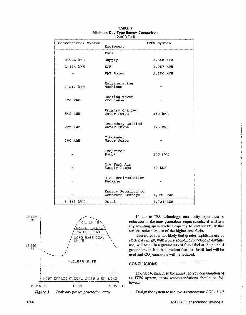
TABLE 7Minimum Day Type Energy Comparison
(2,400 T-H}
Conventional System ITES SystemEquipment
Fans
3,906 kWH Supply 2,640 kWH
1,464 kWH E/R 1,087 kWH
- VAV Boxes 1,280 kWH
Refrigeration1,517 kwh Machines -
Cooling Tower426 kwh /Condenser -
Primary Chilled548 kWH Water Pumps 330 kWH
Secondary Chilled222 kWH Water Pumps 170 kWH
Condenser380 kWH Water Pumps -
Ice/Water- Pumps 155 kWH
Ice Tank Air- Supply Pumps 70 kwh
R-22 Recirculation- Package -
Energy Required to- Generate Storage 1,992 kWH
8,463 kWH Total 7,724 kWH
NUCLEAR UNITS
MOST EFFICIENT COAL UNITS e 1@¼LOAD~ ]
MIDNIGHT
Figure 3
NOON MIDNIGHT
Peak day power generation curve.
If, due to TES technology, one utility experiences areduction in daytime generation requirements, it will sellany resulting spare nuclear capacity to another utility thatcan the reduce its use of the higher cost fuels.
Therefore, it is not likely that greater nighttime use ofelectrical energy, with a corresponding reduction in daytimeuse, will result in a greater use of fossil fuel at the point ofgeneration. In fact, it is evident that less fossil fuel will be
used and COz emissions will be reduced.
CONCLUSIONS
In order to minimize the annual energy consumption ofan ITES system, these recommendations should be fol-lowed:
1. Design the system to achieve a compressor COP of 3.7
1744 ASHRAE Transactions: Symposia
or higher when operating at the time-weighted averageconditions in the storage generation mode.
2. Design the system to allow refrigerant condensingpressure to float down as the ambient temperaturedrops.
3. Select the storage capacity to be capable of providing55 % to 60 % of the highest daily cooling load.
4. Design the chilled-water distribution system to deliver36°F supply water to the cooling coils with a tempera-ture range of 24°F to 28°F.
5. Design the primary air delivery system to provide 46°Fto 48°F at the exit of the air-handling units at peakcooling load conditions.
6. Design the ITES system as an integral part of thebuilding in order to maximize its capabilities within thespecific application.
7. Use adaptive control logic to select ITES system modesof operation based upon maximum efficiency for thethen current conditions.
8. Provide the flowmeters and temperature sensorsrequired to record cooling system capacity output.These data are essential for the operation of the adap-tive control routines and facilitate the commissioning ofthe system.
9. Design the storage system with inventory managementcapability. In an ice-based system, this means notallowing the inventory to accumulate in one area of thestorage vessel. In a chilled-water storage system, thismeans providing effective separation between the warmand cold regions of the storage vessel.
10. Verify that system performance conforms to the design.
REFERENCES
Gillespie and Turnbull. 1991. How is your thermal energystorage system working? 14th World Energy Engineer-ing Congress, Atlanta.
BIBLIOGRAPHY
Steam. lts generation and use. 1955. New York: Babcock& Wilcox Co.
Bauman, F.S., T. Borgers, P. LaBerge, and A.J. Gadgil.1993. Cold air distribution in office buildings: Technol-ogy assessment for California. ASHRAE Transactions99(2): 109-124.
Pearson, S.F. 1990. Therrnosyphon cooling. London: TheInstitute of Refrigeration.
ASHRAE Transactions: Symposia 1745