Embed Size (px)
Citation preview
SENSORSSENSORS
fromADC-001-Sen
SENSORS
Practical Guide toDiscrete Sensors for Industrial Applications
SENSORS
Table of Contents
2
Chapter 2Common Terms Used For Discrete Sensors
Chapter 6Magnetic Proximity Sensor
Chapter 4Limit Switches
Chapter 9Photoelectric Sensor
Chapter 3What Type of Sensor Do I Need?
Chapter 8Ultrasonic Proximity Sensor
Chapter 11Sensors with Analog Output
Chapter 5Inductive Proximity Sensors
Chapter 10Specialty Sensors
Chapter 7Capacitive Proximity Sensor
Jump toChapterChapter 1Introduction to Different Types of Sensors
Chapter 12Conclusion
SENSORS Practical Guide
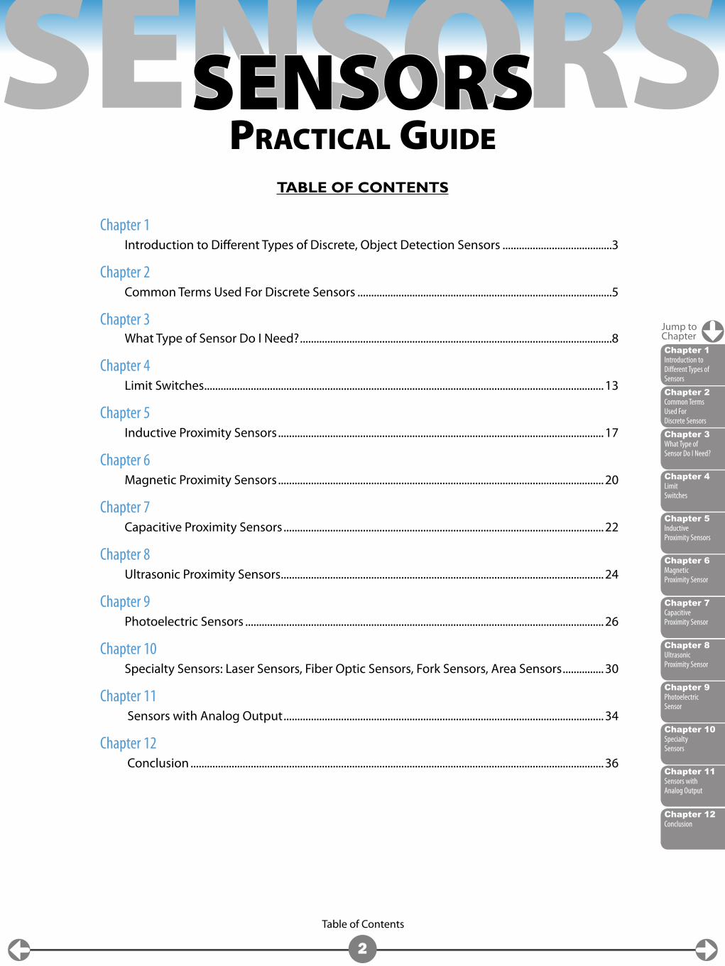
TABLE OF CONTENTS
Chapter 1 Introduction to Different Types of Discrete, Object Detection Sensors ........................................3
Chapter 2 Common Terms Used For Discrete Sensors .............................................................................................5
Chapter 3 What Type of Sensor Do I Need? ..................................................................................................................8
Chapter 4 Limit Switches ..................................................................................................................................................13
Chapter 5 Inductive Proximity Sensors .......................................................................................................................17
Chapter 6 Magnetic Proximity Sensors .......................................................................................................................20
Chapter 7 Capacitive Proximity Sensors .....................................................................................................................22
Chapter 8 Ultrasonic Proximity Sensors ......................................................................................................................24
Chapter 9 Photoelectric Sensors ...................................................................................................................................26
Chapter 10 Specialty Sensors: Laser Sensors, Fiber Optic Sensors, Fork Sensors, Area Sensors ...............30
Chapter 11 Sensors with Analog Output .....................................................................................................................34
Chapter 12 Conclusion .......................................................................................................................................................36
Chapter 2Common Terms Used For Discrete Sensors
Chapter 6Magnetic Proximity Sensor
Chapter 4Limit Switches
Chapter 9Photoelectric Sensor
Chapter 3What Type of Sensor Do I Need?
Chapter 8Ultrasonic Proximity Sensor
Chapter 11Sensors with Analog Output
Chapter 5Inductive Proximity Sensors
Chapter 10Specialty Sensors
Chapter 7Capacitive Proximity Sensor
Chapter 12Conclusion
Chapter 1
3
Chapter 1Introduction to Different Types of Sensors
Jump toChapter
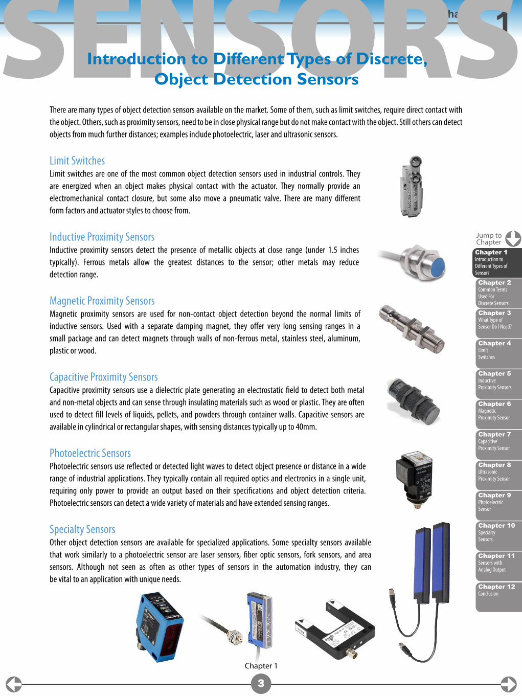
Chapter 1SENSORSThere are many types of object detection sensors available on the market. Some of them, such as limit switches, require direct contact with the object. Others, such as proximity sensors, need to be in close physical range but do not make contact with the object. Still others can detect objects from much further distances; examples include photoelectric, laser and ultrasonic sensors.
Limit SwitchesLimit switches are one of the most common object detection sensors used in industrial controls. They are energized when an object makes physical contact with the actuator. They normally provide an electromechanical contact closure, but some also move a pneumatic valve. There are many different form factors and actuator styles to choose from.
Inductive Proximity SensorsInductive proximity sensors detect the presence of metallic objects at close range (under 1.5 inches typically). Ferrous metals allow the greatest distances to the sensor; other metals may reduce detection range.
Magnetic Proximity SensorsMagnetic proximity sensors are used for non-contact object detection beyond the normal limits of inductive sensors. Used with a separate damping magnet, they offer very long sensing ranges in a small package and can detect magnets through walls of non-ferrous metal, stainless steel, aluminum, plastic or wood.
Capacitive Proximity SensorsCapacitive proximity sensors use a dielectric plate generating an electrostatic field to detect both metal and non-metal objects and can sense through insulating materials such as wood or plastic. They are often used to detect fill levels of liquids, pellets, and powders through container walls. Capacitive sensors are available in cylindrical or rectangular shapes, with sensing distances typically up to 40mm.
Photoelectric SensorsPhotoelectric sensors use reflected or detected light waves to detect object presence or distance in a wide range of industrial applications. They typically contain all required optics and electronics in a single unit, requiring only power to provide an output based on their specifications and object detection criteria. Photoelectric sensors can detect a wide variety of materials and have extended sensing ranges.
Specialty SensorsOther object detection sensors are available for specialized applications. Some specialty sensors available that work similarly to a photoelectric sensor are laser sensors, fiber optic sensors, fork sensors, and area sensors. Although not seen as often as other types of sensors in the automation industry, they can be vital to an application with unique needs.
Introduction to Different Types of Discrete, Object Detection Sensors
SENSORS
Chapter 2Common Terms Used For Discrete Sensors
Chapter 6Magnetic Proximity Sensor
Chapter 4Limit Switches
Chapter 9Photoelectric Sensor
Chapter 3What Type of Sensor Do I Need?
Chapter 8Ultrasonic Proximity Sensor
Chapter 11Sensors with Analog Output
Chapter 5Inductive Proximity Sensors
Chapter 10Specialty Sensors
Chapter 7Capacitive Proximity Sensor
Chapter 1Introduction to Different Types of Sensors
Chapter 12Conclusion
Chapter 1
4
Jump toChapter
Introduction to Different Types of Discrete, Object Detection SensorsChapter 1
SENSORS
Chapter 6Magnetic Proximity Sensor
Chapter 4Limit Switches
Chapter 9Photoelectric Sensor
Chapter 3What Type of Sensor Do I Need?
Chapter 8Ultrasonic Proximity Sensor
Chapter 11Sensors with Analog Output
Chapter 5Inductive Proximity Sensors
Chapter 10Specialty Sensors
Chapter 7Capacitive Proximity Sensor
Chapter 1Introduction to Different Types of Sensors
Chapter 12Conclusion
Chapter 2
5
Chapter 2Common Terms Used For
Discrete Sensors
Sensors have many different options when it comes to the output signal. The output can be an electromechanical relay contact or it can be solid state. If it is a solid state output, then the logic can be NPN or PNP. Either type of output can be Normally Open or Normally Closed.
Electromechanical Relay Contact vs. Solid State OutputAn electromechanical relay output uses a physical set of contacts that open or close to switch a signal. This works very similarly to a light switch in your house. It is either fully open or fully closed. The advantages of a relay contact output are that the signal is either fully ON or fully OFF and this type of output circuit usually can handle much higher current draw through it. A drawback of a relay contact is that since it is mechanical, it will eventually wear out after extended use and either weld closed or be stuck open. Most limit switches offer this as their output circuit type, although some other sensors may have this as an option as well.
A solid-state output uses a purely electrical device to switch the output signal. An example of a solid state device would be a transistor, MOSFET, SCR, or Triac. Solid state devices use no moving or mechanical parts and essentially have an infinite lifespan if they are not overloaded. They are smaller than relay contacts and make no noise when switching the output signal. Some drawbacks to solid state devices are that they usually do not handle as much current as a relay contact, and they are never truly completely OFF or completely ON so they will have some leakage current in their OFF or open state.
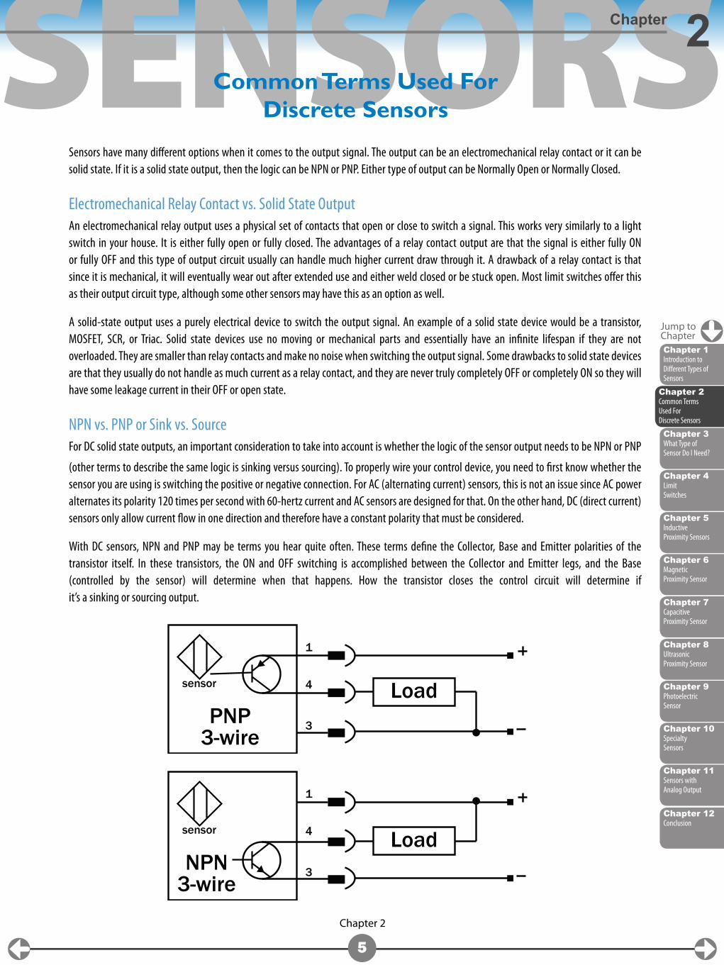
NPN vs. PNP or Sink vs. SourceFor DC solid state outputs, an important consideration to take into account is whether the logic of the sensor output needs to be NPN or PNP
(other terms to describe the same logic is sinking versus sourcing). To properly wire your control device, you need to first know whether the sensor you are using is switching the positive or negative connection. For AC (alternating current) sensors, this is not an issue since AC power alternates its polarity 120 times per second with 60-hertz current and AC sensors are designed for that. On the other hand, DC (direct current) sensors only allow current flow in one direction and therefore have a constant polarity that must be considered.
With DC sensors, NPN and PNP may be terms you hear quite often. These terms define the Collector, Base and Emitter polarities of the transistor itself. In these transistors, the ON and OFF switching is accomplished between the Collector and Emitter legs, and the Base (controlled by the sensor) will determine when that happens. How the transistor closes the control circuit will determine if it’s a sinking or sourcing output.
1
4
3
sensor
PNP3-wire
Load
1
4
3
sensor
NPN3-wire
Load
Chapter 2Common Terms Used For Discrete Sensors
Jump toChapter
SENSORS
Chapter 12Conclusion
Chapter 2
6
Common Terms Used For Discrete SensorsChapter 2
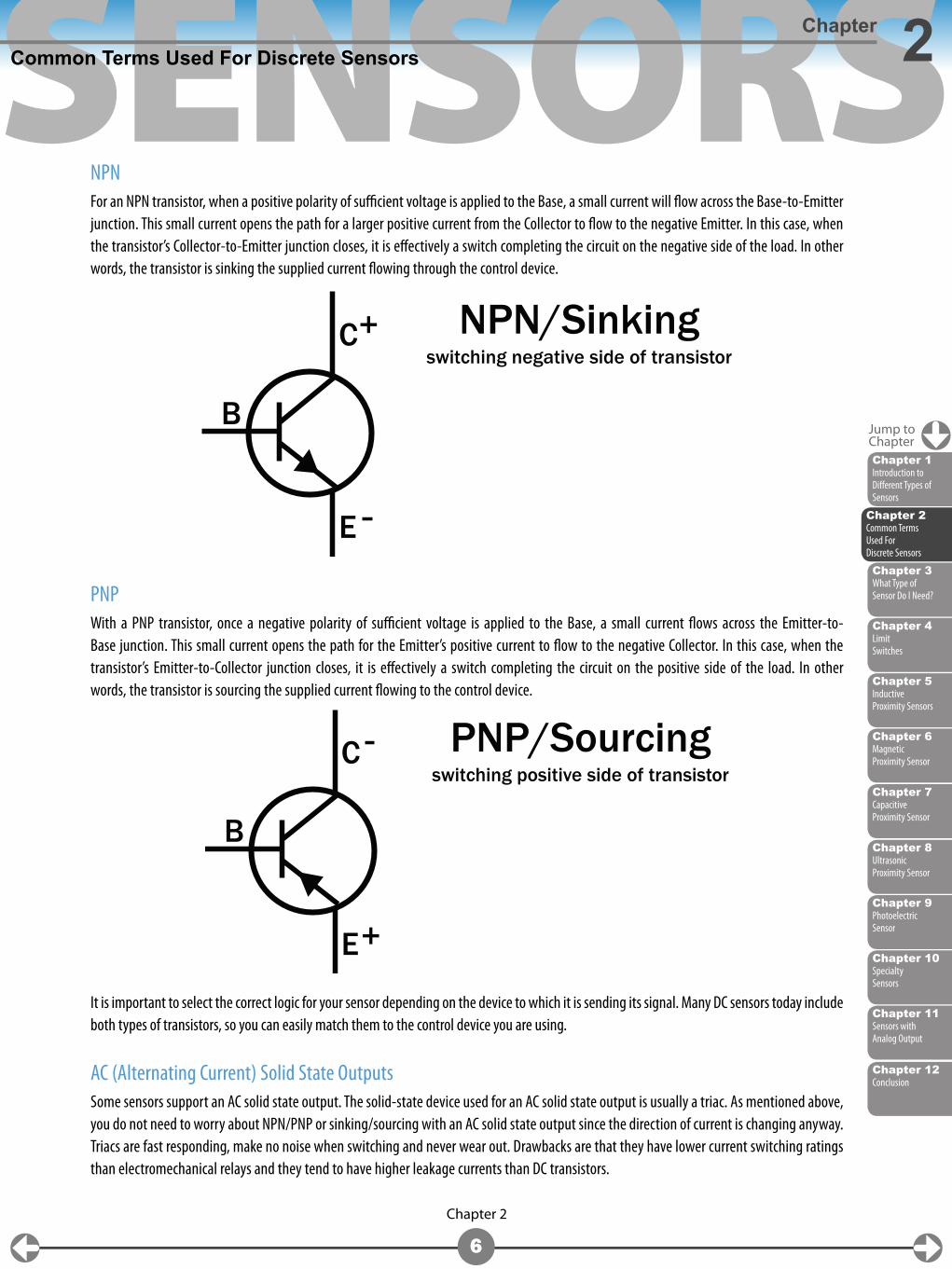
NPNFor an NPN transistor, when a positive polarity of sufficient voltage is applied to the Base, a small current will flow across the Base-to-Emitter junction. This small current opens the path for a larger positive current from the Collector to flow to the negative Emitter. In this case, when the transistor’s Collector-to-Emitter junction closes, it is effectively a switch completing the circuit on the negative side of the load. In other words, the transistor is sinking the supplied current flowing through the control device.
PNPWith a PNP transistor, once a negative polarity of sufficient voltage is applied to the Base, a small current flows across the Emitter-to-Base junction. This small current opens the path for the Emitter’s positive current to flow to the negative Collector. In this case, when the transistor’s Emitter-to-Collector junction closes, it is effectively a switch completing the circuit on the positive side of the load. In other words, the transistor is sourcing the supplied current flowing to the control device.
It is important to select the correct logic for your sensor depending on the device to which it is sending its signal. Many DC sensors today include both types of transistors, so you can easily match them to the control device you are using.
AC (Alternating Current) Solid State OutputsSome sensors support an AC solid state output. The solid-state device used for an AC solid state output is usually a triac. As mentioned above, you do not need to worry about NPN/PNP or sinking/sourcing with an AC solid state output since the direction of current is changing anyway. Triacs are fast responding, make no noise when switching and never wear out. Drawbacks are that they have lower current switching ratings than electromechanical relays and they tend to have higher leakage currents than DC transistors.
B
C
E
NPN/Sinkingswitching negative side of transistor
+
B
C
E
PNP/Sourcingswitching positive side of transistor
+
Jump toChapter
Chapter 6Magnetic Proximity Sensor
Chapter 4Limit Switches
Chapter 9Photoelectric Sensor
Chapter 3What Type of Sensor Do I Need?
Chapter 8Ultrasonic Proximity Sensor
Chapter 11Sensors with Analog Output
Chapter 5Inductive Proximity Sensors
Chapter 10Specialty Sensors
Chapter 7Capacitive Proximity Sensor
Chapter 1Introduction to Different Types of Sensors
Chapter 2Common Terms Used For Discrete Sensors
SENSORS
Chapter 12Conclusion
Chapter 2
7
Common Terms Used For Discrete SensorsChapter 2
Normally Open vs. Normally Closed (NO/NC)Normally open versus normally closed are terms used to describe whether the output is ON or OFF based on the sensor’s normal state. This is a throwback term from when the only output option was a relay contact and solid state switches didn’t exist. However, today we use the same terms to describe solid-state or relay outputs.
If the output is described as being closed, then the output is ON, just like when a relay contact or light switch is closed the output will be ON. When an output is described as being open then the output is OFF, exactly the opposite of being closed.
The “normal” state of a sensor means that the sensor is not detecting an object.
So for example, if any type of sensor has a normally open output and it does not detect an object, then the output will be OFF and will turn ON when it detects an object.
Likewise, if a sensor has a normally closed output, the output will be ON when it does NOT detect an object and the output will then turn OFF when an object is detected.
Environmental RatingsAll sensors offer some degree of protection from environmental factors such as moisture and debris. Ingress Protection (IP) ratings are established by the IEC and define the protection offered by electrical devices and their enclosures. It is similar to the NEMA rating system. IP ratings of IP65 or higher are very common for most sensors. Harsh duty models are also available and can have ratings as high as IP69K. IP69K is often required in the food and beverage industry where the sensors must withstand “washdown” cleaning procedures, often with harsh chemicals.
Connection optionsSensors may offer a threaded conduit fitting, an attached (embedded) cable or a quick-disconnect (Q/D) fitting to which a mating cable can be attached.
Threaded conduit connection On many limit switches, the connection is a threaded conduit connection opening in which individual wires can be terminated. Usually, this is either a female NPT or female PG threaded connection.
Attached cables Attached cables (embedded) are typically 6 feet (2m) in length and are molded into the body of the sensor at the attachment point. They are typically the less-expensive option. The cable can be cut to length, or may not be long enough to reach all the way to the termination point controller. Field junction boxes may be required, and numerous sensor signals are often combined into multi-conductor cables at such junction points. Lastly, a cable exiting from the end of the sensor body may not fit (physically) in all applications.
Quick-disconnects Sensors with quick disconnect fittings require the use of a separate cable to complete the installation. These cables typically include industry-standard M8, M12, or micro-AC (for some AC powered sensors) style connections on one end and offer a pigtail (flying leads) on the other end for completing the connection. These quick-disconnects offer several advantages: it’s very easy to replace a damaged sensor without any rewiring, and the cables are available in longer lengths with axial or 90-degree connections at the sensor. Field-wireable quick-disconnect connectors are also available for constructing custom cables.
Jump toChapter
Chapter 6Magnetic Proximity Sensor
Chapter 4Limit Switches
Chapter 9Photoelectric Sensor
Chapter 3What Type of Sensor Do I Need?
Chapter 8Ultrasonic Proximity Sensor
Chapter 11Sensors with Analog Output
Chapter 5Inductive Proximity Sensors
Chapter 10Specialty Sensors
Chapter 7Capacitive Proximity Sensor
Chapter 1Introduction to Different Types of Sensors
Chapter 2Common Terms Used For Discrete Sensors
SENSORS
Chapter 2Common Terms Used For Discrete Sensors
Chapter 6Magnetic Proximity Sensor
Chapter 4Limit Switches
Chapter 9Photoelectric Sensor
Chapter 8Ultrasonic Proximity Sensor
Chapter 11Sensors with Analog Output
Chapter 5Inductive Proximity Sensors
Chapter 10Specialty Sensors
Chapter 7Capacitive Proximity Sensor
Chapter 1Introduction to Different Types of Sensors
Chapter 12Conclusion
Chapter 3
8
Chapter 3
There are many factors that will determine the “best” sensor to use for a given application. Experience is the best teacher when it comes to selecting sensors. However, there are a few questions that can be asked to help narrow down your selection to a sensor type.
Keep in mind that this chapter will help you narrow down your choice to a particular family. There is no ironclad guarantee that this will be the absolute correct solution. A lot of this comes down to good old fashioned common-sense and experience. So keep that in mind when going through this chapter and of course if you have any questions feel free to call our FREE technical support service between the hours of 9 AM and 6 PM Eastern Time at 800-633-0405.
What Are You Trying to Detect?Are you trying to detect a solid object or a liquid/powder/pellet/grain ❑ I am trying to detect a liquid, powder, pellet or grain ❑ I am trying to detect a solid object
Would you like to detect a magnet from up to 70mm away? (Can be through non-magnetizable materials)? ❑ Magnetic Proximity Sensors
What Type of Sensor Do I Need?
Chapter 3What Type of Sensor Do I Need?
Jump toChapter
SENSORS
Chapter 12Conclusion
Chapter 3
9
What Type of Sensor Do I Need?Chapter 3
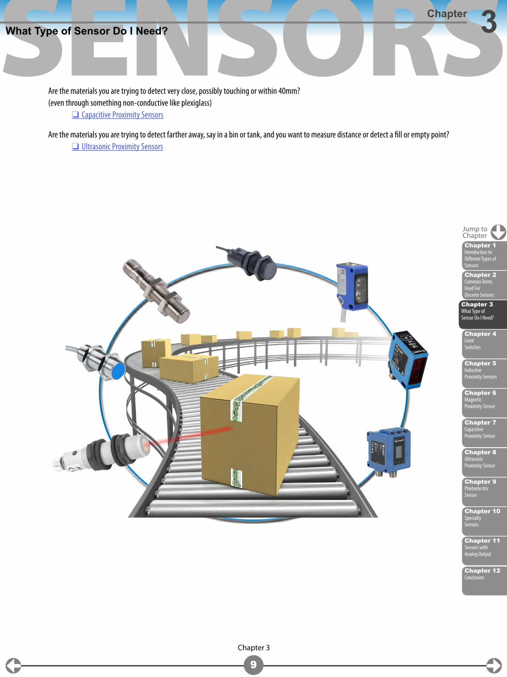
Are the materials you are trying to detect very close, possibly touching or within 40mm?(even through something non-conductive like plexiglass) ❑ Capacitive Proximity Sensors
Are the materials you are trying to detect farther away, say in a bin or tank, and you want to measure distance or detect a fill or empty point? ❑ Ultrasonic Proximity Sensors
Jump toChapter
Chapter 2Common Terms Used For Discrete Sensors
Chapter 6Magnetic Proximity Sensor
Chapter 4Limit Switches
Chapter 9Photoelectric Sensor
Chapter 8Ultrasonic Proximity Sensor
Chapter 11Sensors with Analog Output
Chapter 5Inductive Proximity Sensors
Chapter 10Specialty Sensors
Chapter 7Capacitive Proximity Sensor
Chapter 1Introduction to Different Types of Sensors
Chapter 3What Type of Sensor Do I Need?
SENSORS
Chapter 12Conclusion
Chapter 3
10
What Type of Sensor Do I Need?Chapter 3
If the object will be touching the sensor actuator or sensing face, then most likely a limit switch will be the solution to your sensor selection.❑ limit switches.
If your object is metal you may also want to look at❑ capacitive proximity sensors❑ inductive proximity sensors
If the object is not touching, then we need to continue with narrowing your selection:
Is your object closer or farther away than 40mm?❑ The object I wish to detect is closer than 40mm❑ The object I wish to detect is farther away than 40mm
Jump toChapter
Chapter 2Common Terms Used For Discrete Sensors
Chapter 6Magnetic Proximity Sensor
Chapter 4Limit Switches
Chapter 9Photoelectric Sensor
Chapter 8Ultrasonic Proximity Sensor
Chapter 11Sensors with Analog Output
Chapter 5Inductive Proximity Sensors
Chapter 10Specialty Sensors
Chapter 7Capacitive Proximity Sensor
Chapter 1Introduction to Different Types of Sensors
Chapter 3What Type of Sensor Do I Need?
SENSORS
Chapter 12Conclusion
Chapter 3
11
What Type of Sensor Do I Need?Chapter 3
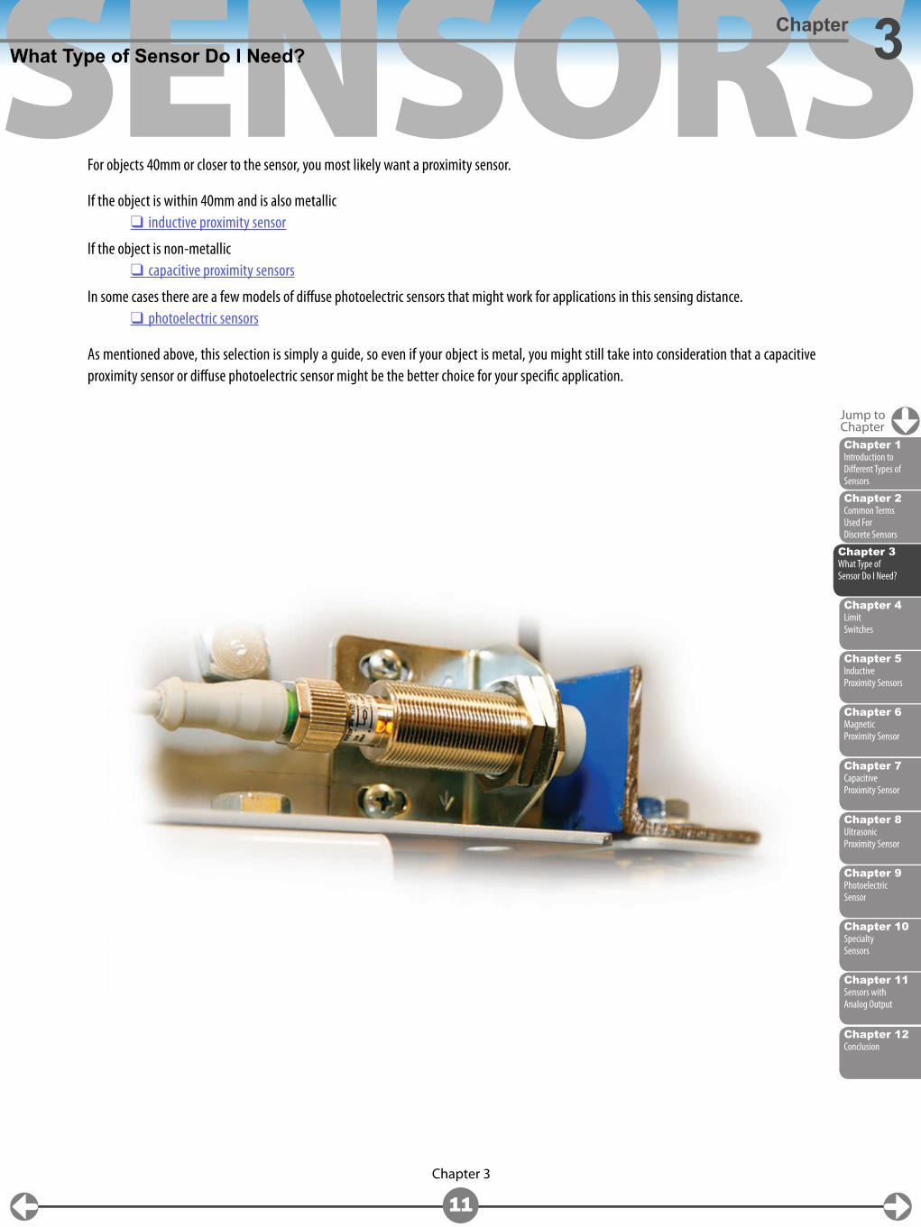
For objects 40mm or closer to the sensor, you most likely want a proximity sensor.
If the object is within 40mm and is also metallic ❑ inductive proximity sensor
If the object is non-metallic ❑ capacitive proximity sensors
In some cases there are a few models of diffuse photoelectric sensors that might work for applications in this sensing distance. ❑ photoelectric sensors
As mentioned above, this selection is simply a guide, so even if your object is metal, you might still take into consideration that a capacitive proximity sensor or diffuse photoelectric sensor might be the better choice for your specific application.
Jump toChapter
Chapter 2Common Terms Used For Discrete Sensors
Chapter 6Magnetic Proximity Sensor
Chapter 4Limit Switches
Chapter 9Photoelectric Sensor
Chapter 8Ultrasonic Proximity Sensor
Chapter 11Sensors with Analog Output
Chapter 5Inductive Proximity Sensors
Chapter 10Specialty Sensors
Chapter 7Capacitive Proximity Sensor
Chapter 1Introduction to Different Types of Sensors
Chapter 3What Type of Sensor Do I Need?
SENSORS
Chapter 12Conclusion
Chapter 3
12
What Type of Sensor Do I Need?Chapter 3
So if your object is farther away than 40mm from the sensor, then a proximity sensor is out of the question. To narrow things down farther, it will help you to know more about your application, most importantly the size of the object, the exact distance from the object to the sensing face, and the color of the object to be detected (Is it a light, reflective color or is it darker, like black, dark gray or brown?). Knowing if the application allows you to put components on either side of the sensing area (i.e. a reflector or emitter for photoelectric sensors) is helpful.
If your item is larger and application requires less accuracy (think detecting a fork truck near a machine as opposed to a small box on a specific location on a conveyor) ❑ ultrasonic sensor.
Now, keep in mind that ultrasonic sensors can detect up to 6,000mm and have a deadband close to the sensor. They are also not as accurate as photoelectric sensors and do not do as great of a job detecting smaller objects.
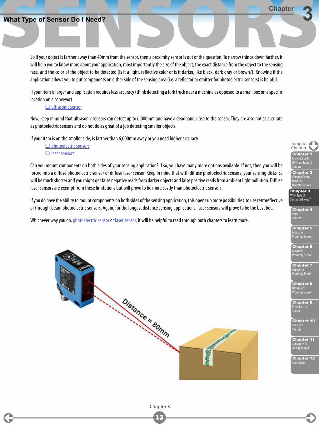
If your item is on the smaller side, is farther than 6,000mm away or you need higher accuracy ❑ photoelectric sensors ❑ laser sensors
Can you mount components on both sides of your sensing application? If so, you have many more options available. If not, then you will be forced into a diffuse photoelectric sensor or diffuse laser sensor. Keep in mind that with diffuse photoelectric sensors, your sensing distance will be much shorter and you might get false negative reads from darker objects and false positive reads from ambient light pollution. Diffuse laser sensors are exempt from these limitations but will prove to be more costly than photoelectric sensors.
If you do have the ability to mount components on both sides of the sensing application, this opens up more possibilities to use retroreflective or through-beam photoelectric sensors. Again, for the longest distance sensing applications, laser sensors will prove to be the best bet.
Whichever way you go, photoelectric sensor or laser sensor, it will be helpful to read through both chapters to learn more.
Jump toChapter
Chapter 2Common Terms Used For Discrete Sensors
Chapter 6Magnetic Proximity Sensor
Chapter 4Limit Switches
Chapter 9Photoelectric Sensor
Chapter 8Ultrasonic Proximity Sensor
Chapter 11Sensors with Analog Output
Chapter 5Inductive Proximity Sensors
Chapter 10Specialty Sensors
Chapter 7Capacitive Proximity Sensor
Chapter 1Introduction to Different Types of Sensors
Chapter 3What Type of Sensor Do I Need?
SENSORS
Chapter 2Common Terms Used For Discrete Sensors
Chapter 6Magnetic Proximity Sensor
Chapter 9Photoelectric Sensor
Chapter 3What Type of Sensor Do I Need?
Chapter 8Ultrasonic Proximity Sensor
Chapter 11Sensors with Analog Output
Chapter 5Inductive Proximity Sensors
Chapter 10Specialty Sensors
Chapter 7Capacitive Proximity Sensor
Chapter 1Introduction to Different Types of Sensors
Chapter 12Conclusion
Chapter 4
13
Chapter 4
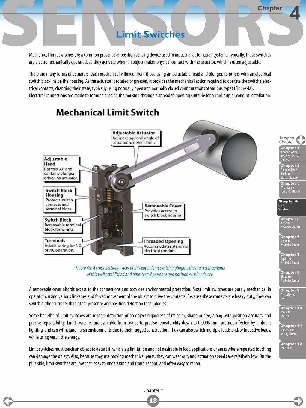
Mechanical limit switches are a common presence or position sensing device used in industrial automation systems. Typically, these switches are electromechanically operated, so they activate when an object makes physical contact with the actuator, which is often adjustable.
There are many forms of actuators, each mechanically linked, from those using an adjustable head and plunger, to others with an electrical switch block inside the housing. As the actuator is rotated or pressed, it provides the mechanical action required to operate the switch’s elec-trical contacts, changing their state, typically using normally open and normally closed configurations of various types (Figure 4a).Electrical connections are made to terminals inside the housing through a threaded opening suitable for a cord grip or conduit installation.
A removable cover affords access to the connections and provides environmental protection. Most limit switches are purely mechanical in operation, using various linkages and forced movement of the object to drive the contacts. Because these contacts are heavy duty, they can switch higher currents than other presence and position detection technologies.
Some benefits of limit switches are reliable detection of an object regardless of its color, shape or size, along with position accuracy and precise repeatability. Limit switches are available from coarse to precise repeatability down to 0.0005 mm, are not affected by ambient lighting, and can withstand harsh environments due to their rugged construction. They can also switch multiple loads and/or inductive loads, while using very little energy.
Limit switches must touch an object to detect it, which is a limitation and not desirable in food applications or areas where repeated touching can damage the object. Also, because they use moving mechanical parts, they can wear out, and actuation speeds are relatively low. On the plus side, limit switches are low cost, easy to understand and troubleshoot, and often easy to repair.
Limit Switches
Figure 4a: A cross-sectional view of this Eaton limit switch highlights the main components of this well established and time-tested presence and position sensing device.
Chapter 4Limit Switches
Jump toChapter
SENSORS
Chapter 12Conclusion
Chapter 4
14
Limit SwitchesChapter 4
Selection Considerations
It is important to study the specifications and understand limit switch terminology such as maximum switching frequency, travel to operate, total travel, repeatability, force to operate, etc. With the specifications considered, the limit switch selected should be first based on environ-mental factors and available space, then chosen by actuator style based on the mechanical setup of an application.
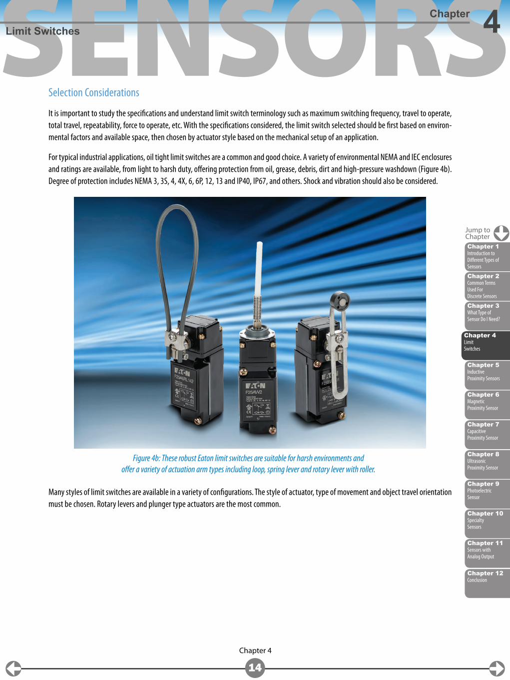
For typical industrial applications, oil tight limit switches are a common and good choice. A variety of environmental NEMA and IEC enclosures and ratings are available, from light to harsh duty, offering protection from oil, grease, debris, dirt and high-pressure washdown (Figure 4b). Degree of protection includes NEMA 3, 3S, 4, 4X, 6, 6P, 12, 13 and IP40, IP67, and others. Shock and vibration should also be considered.
Many styles of limit switches are available in a variety of configurations. The style of actuator, type of movement and object travel orientation must be chosen. Rotary levers and plunger type actuators are the most common.
Figure 4b: These robust Eaton limit switches are suitable for harsh environments and offer a variety of actuation arm types including loop, spring lever and rotary lever with roller.
Jump toChapter
Chapter 2Common Terms Used For Discrete Sensors
Chapter 6Magnetic Proximity Sensor
Chapter 9Photoelectric Sensor
Chapter 3What Type of Sensor Do I Need?
Chapter 8Ultrasonic Proximity Sensor
Chapter 11Sensors with Analog Output
Chapter 5Inductive Proximity Sensors
Chapter 10Specialty Sensors
Chapter 7Capacitive Proximity Sensor
Chapter 1Introduction to Different Types of Sensors
Chapter 4Limit Switches
SENSORS
Chapter 12Conclusion
Chapter 4
15
Limit SwitchesChapter 4
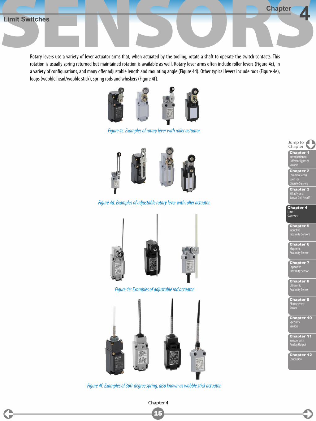
Rotary levers use a variety of lever actuator arms that, when actuated by the tooling, rotate a shaft to operate the switch contacts. This rotation is usually spring returned but maintained rotation is available as well. Rotary lever arms often include roller levers (Figure 4c), in a variety of configurations, and many offer adjustable length and mounting angle (Figure 4d). Other typical levers include rods (Figure 4e), loops (wobble head/wobble stick), spring rods and whiskers (Figure 4f).
Figure 4c: Examples of rotary lever with roller actuator.
Figure 4d: Examples of adjustable rotary lever with roller actuator.
Figure 4e: Examples of adjustable rod actuator.
Figure 4f: Examples of 360-degree spring, also known as wobble stick actuator.
Jump toChapter
Chapter 2Common Terms Used For Discrete Sensors
Chapter 6Magnetic Proximity Sensor
Chapter 9Photoelectric Sensor
Chapter 3What Type of Sensor Do I Need?
Chapter 8Ultrasonic Proximity Sensor
Chapter 11Sensors with Analog Output
Chapter 5Inductive Proximity Sensors
Chapter 10Specialty Sensors
Chapter 7Capacitive Proximity Sensor
Chapter 1Introduction to Different Types of Sensors
Chapter 4Limit Switches
SENSORS
Chapter 12Conclusion
Chapter 4
16
Limit SwitchesChapter 4
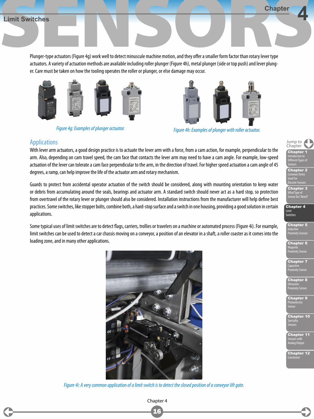
Plunger-type actuators (Figure 4g) work well to detect minuscule machine motion, and they offer a smaller form factor than rotary lever type actuators. A variety of actuation methods are available including roller plunger (Figure 4h), metal plunger (side or top push) and lever plung-er. Care must be taken on how the tooling operates the roller or plunger, or else damage may occur.
ApplicationsWith lever arm actuators, a good design practice is to actuate the lever arm with a force, from a cam action, for example, perpendicular to the arm. Also, depending on cam travel speed, the cam face that contacts the lever arm may need to have a cam angle. For example, low-speed actuation of the lever can tolerate a cam face perpendicular to the arm, in the direction of travel. For higher speed actuation a cam angle of 45 degrees, a ramp, can help improve the life of the actuator arm and rotary mechanism.
Guards to protect from accidental operator actuation of the switch should be considered, along with mounting orientation to keep water or debris from accumulating around the seals, bearings and actuator arm. A standard switch should never act as a hard stop, so protection from overtravel of the rotary lever or plunger should also be considered. Installation instructions from the manufacturer will help define best practices. Some switches, like stopper bolts, combine both, a hard-stop surface and a switch in one housing, providing a good solution in certain applications.
Some typical uses of limit switches are to detect flags, carriers, trollies or travelers on a machine or automated process (Figure 4i). For example, limit switches can be used to detect a car chassis moving on a conveyor, a position of an elevator in a shaft, a roller coaster as it comes into the loading zone, and in many other applications.
Figure 4g: Examples of plunger actuator.
Figure 4i: A very common application of a limit switch is to detect the closed position of a conveyor lift gate.
Figure 4h: Examples of plunger with roller actuator.
Jump toChapter
Chapter 2Common Terms Used For Discrete Sensors
Chapter 6Magnetic Proximity Sensor
Chapter 9Photoelectric Sensor
Chapter 3What Type of Sensor Do I Need?
Chapter 8Ultrasonic Proximity Sensor
Chapter 11Sensors with Analog Output
Chapter 5Inductive Proximity Sensors
Chapter 10Specialty Sensors
Chapter 7Capacitive Proximity Sensor
Chapter 1Introduction to Different Types of Sensors
Chapter 4Limit Switches
SENSORS
Chapter 2Common Terms Used For Discrete Sensors
Chapter 6Magnetic Proximity Sensor
Chapter 4Limit Switches
Chapter 9Photoelectric Sensor
Chapter 3What Type of Sensor Do I Need?
Chapter 8Ultrasonic Proximity Sensor
Chapter 11Sensors with Analog Output
Chapter 10Specialty Sensors
Chapter 7Capacitive Proximity Sensor
Chapter 1Introduction to Different Types of Sensors
Chapter 12Conclusion
Chapter 5
17
Chapter 5
What is an Inductive Proximity Sensor?Proximity sensors allow non-contact detection of metallic objects up to close range (up to 1.5 inches typically) using an inductive field. In particular, the presence of parts and/or machine elements can be detected for the purpose of counting, indexing, verification, end-of-stroke or travel, determining orientation, and many other common automation tasks.
Selection CriteriaSome common selection criteria for inductive proximity sensors include sensing distance, size/shape, switching frequency, ingress rating, flush vs non-flush, housing material, correction factor of 1, and weld slag resistance.
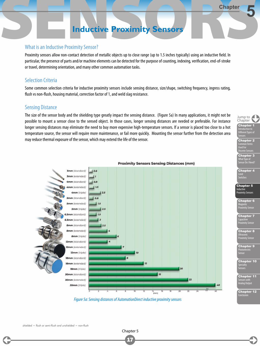
Sensing DistanceThe size of the sensor body and the shielding type greatly impact the sensing distance. (Figure 5a) In many applications, it might not be possible to mount a sensor close to the sensed object. In those cases, longer sensing distances are needed or preferable. For instance longer sensing distances may eliminate the need to buy more expensive high-temperature sensors. If a sensor is placed too close to a hot temperature source, the sensor will require more maintenance, or fail more quickly. Mounting the sensor further from the detection area may reduce thermal exposure of the sensor, which may extend the life of the sensor.
Inductive Proximity Sensors
Figure 5a: Sensing distances of AutomationDirect inductive proximity sensors
shielded = flush or semi-flush and unshielded = non-flush
Jump toChapter
Chapter 5Inductive Proximity Sensors
SENSORS
Chapter 12Conclusion
Chapter 5
18
Inductive Proximity SensorsChapter 5
Size and ShapeInductive proximity sensors are available in a vast assortment of sizes and shapes, from tiny 3mm barrels to 30mm cylindrical bodies, and in many rectangular form factors.
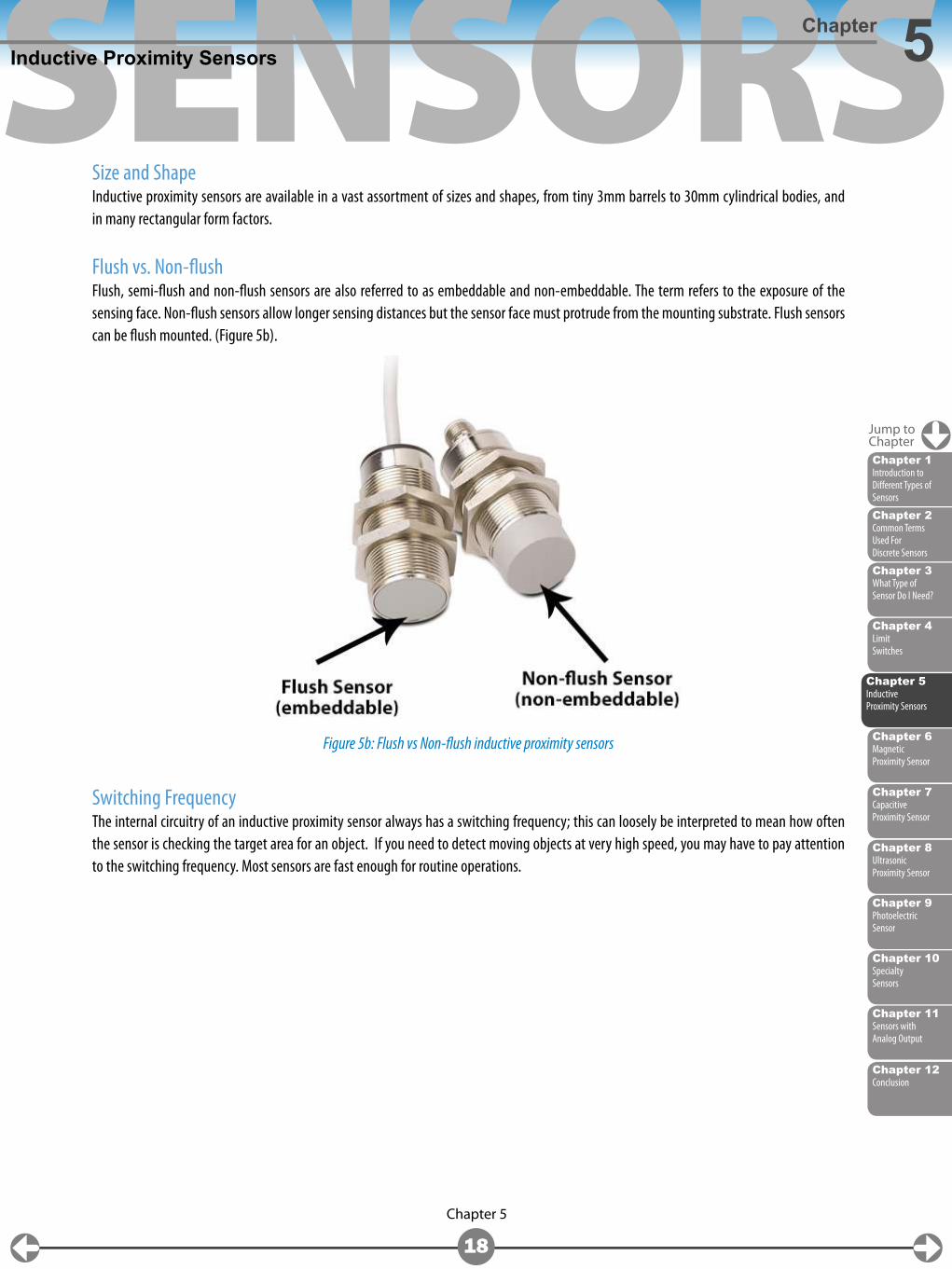
Flush vs. Non-flushFlush, semi-flush and non-flush sensors are also referred to as embeddable and non-embeddable. The term refers to the exposure of the sensing face. Non-flush sensors allow longer sensing distances but the sensor face must protrude from the mounting substrate. Flush sensors can be flush mounted. (Figure 5b).
Switching FrequencyThe internal circuitry of an inductive proximity sensor always has a switching frequency; this can loosely be interpreted to mean how often the sensor is checking the target area for an object. If you need to detect moving objects at very high speed, you may have to pay attention to the switching frequency. Most sensors are fast enough for routine operations.
Figure 5b: Flush vs Non-flush inductive proximity sensors
Jump toChapter
Chapter 2Common Terms Used For Discrete Sensors
Chapter 6Magnetic Proximity Sensor
Chapter 4Limit Switches
Chapter 9Photoelectric Sensor
Chapter 3What Type of Sensor Do I Need?
Chapter 8Ultrasonic Proximity Sensor
Chapter 11Sensors with Analog Output
Chapter 10Specialty Sensors
Chapter 7Capacitive Proximity Sensor
Chapter 1Introduction to Different Types of Sensors
Chapter 5Inductive Proximity Sensors
SENSORS
Chapter 12Conclusion
Chapter 5
19
Inductive Proximity SensorsChapter 5
Output TypeAs mentioned in chapter 2 of this eBook, the type of output required must be determined (i.e., NPN, PNP, or analog). Most PLC inputs will accept either NPN or PNP output types. If connecting to a solid state relay, a PNP output is needed. The need for an analog output is determined by the application. Sensors with analog outputs produce a signal approximately proportional to the target distance.
Do you need 2, 3, or 4-wire discrete outputs? This may be dictated by the device to which the sensor will be connected, or it may be a personal preference.
Some simple guidelines to use are:
2-wire • Will work with sinking or sourcing devices • Only 2 wires to terminate • Higher leakage current
3-wire • Most popular variety – familiar to most users • Must select between NPN and PNP outputs
4-wire • Allows flexibility of configuration in one device • May have both NPN/PNP selection or NO/NC selection • Allows the user to stock one part for numerous applications
Correction FactorMost Inductive proximity sensors require a correction factor to be factored in when detecting non-ferrous metals such as aluminum or stainless steel. The correction factor reduces the overall sensing distance when detecting non-ferrous metals. Inductive proximity sensors are available that have a correction factor (K-factor) of 1 for all metals so that this adjustment does not have to be made for non-ferrous metals.
Other Selection ConsiderationsOf course, the environmental ratings may have an impact on your selection of a sensor. Inductive proximity sensors usually have, at minimum, IP65 environmental ratings but are available up to an IP69K rating as well. If an inductive proximity sensor is going to be used in or near a welding application, then an inductive proximity sensor with weld slag resistance is a good choice to keep weld slag from building up on the sensor.
Jump toChapter
Chapter 2Common Terms Used For Discrete Sensors
Chapter 6Magnetic Proximity Sensor
Chapter 4Limit Switches
Chapter 9Photoelectric Sensor
Chapter 3What Type of Sensor Do I Need?
Chapter 8Ultrasonic Proximity Sensor
Chapter 11Sensors with Analog Output
Chapter 10Specialty Sensors
Chapter 7Capacitive Proximity Sensor
Chapter 1Introduction to Different Types of Sensors
Chapter 5Inductive Proximity Sensors
SENSORS
Chapter 2Common Terms Used For Discrete Sensors
Chapter 4Limit Switches
Chapter 9Photoelectric Sensor
Chapter 3What Type of Sensor Do I Need?
Chapter 8Ultrasonic Proximity Sensor
Chapter 11Sensors with Analog Output
Chapter 5Inductive Proximity Sensors
Chapter 10Specialty Sensors
Chapter 7Capacitive Proximity Sensor
Chapter 1Introduction to Different Types of Sensors
Chapter 12Conclusion
Chapter 6
20
Chapter 6
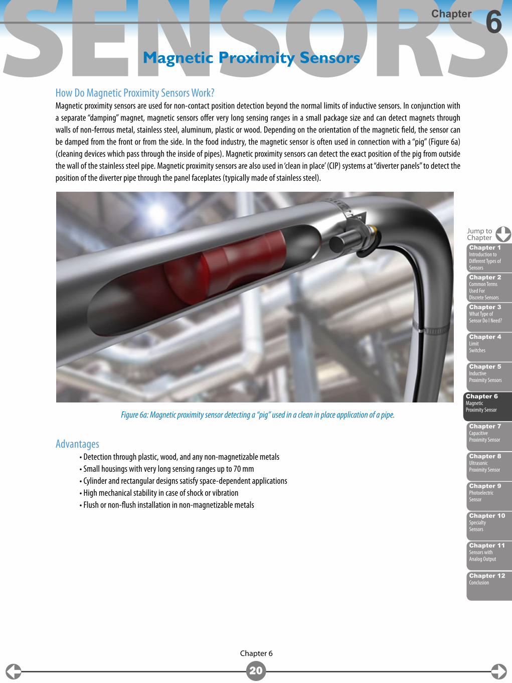
How Do Magnetic Proximity Sensors Work?Magnetic proximity sensors are used for non-contact position detection beyond the normal limits of inductive sensors. In conjunction with a separate “damping” magnet, magnetic sensors offer very long sensing ranges in a small package size and can detect magnets through walls of non-ferrous metal, stainless steel, aluminum, plastic or wood. Depending on the orientation of the magnetic field, the sensor can be damped from the front or from the side. In the food industry, the magnetic sensor is often used in connection with a “pig” (Figure 6a) (cleaning devices which pass through the inside of pipes). Magnetic proximity sensors can detect the exact position of the pig from outside the wall of the stainless steel pipe. Magnetic proximity sensors are also used in ‘clean in place’ (CIP) systems at “diverter panels” to detect the position of the diverter pipe through the panel faceplates (typically made of stainless steel).
Advantages • Detection through plastic, wood, and any non-magnetizable metals • Small housings with very long sensing ranges up to 70 mm • Cylinder and rectangular designs satisfy space-dependent applications • High mechanical stability in case of shock or vibration • Flush or non-flush installation in non-magnetizable metals
Magnetic Proximity Sensors
Figure 6a: Magnetic proximity sensor detecting a “pig” used in a clean in place application of a pipe.
Jump toChapter
Chapter 6Magnetic Proximity Sensor
SENSORS
Chapter 2Common Terms Used For Discrete Sensors
Chapter 4Limit Switches
Chapter 9Photoelectric Sensor
Chapter 3What Type of Sensor Do I Need?
Chapter 8Ultrasonic Proximity Sensor
Chapter 11Sensors with Analog Output
Chapter 5Inductive Proximity Sensors
Chapter 10Specialty Sensors
Chapter 7Capacitive Proximity Sensor
Chapter 1Introduction to Different Types of Sensors
Chapter 6Magnetic Proximity Sensor
Chapter 12Conclusion
Chapter 6
21
Magnetic Proximity SensorsChapter 6
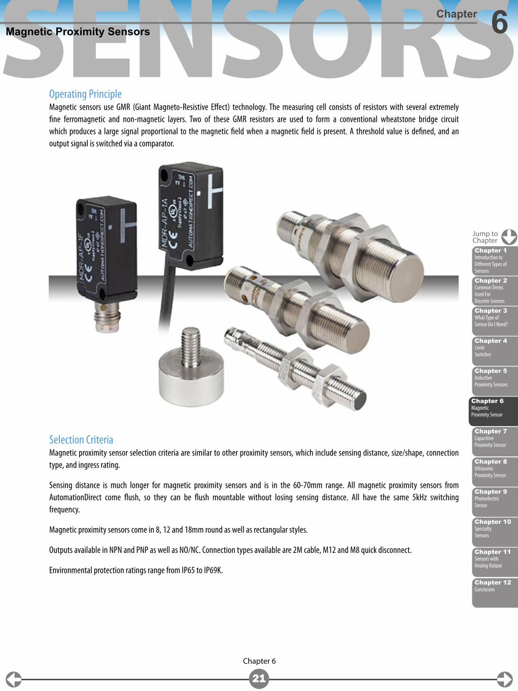
Operating PrincipleMagnetic sensors use GMR (Giant Magneto-Resistive Effect) technology. The measuring cell consists of resistors with several extremely fine ferromagnetic and non-magnetic layers. Two of these GMR resistors are used to form a conventional wheatstone bridge circuit which produces a large signal proportional to the magnetic field when a magnetic field is present. A threshold value is defined, and an output signal is switched via a comparator.
Selection CriteriaMagnetic proximity sensor selection criteria are similar to other proximity sensors, which include sensing distance, size/shape, connection type, and ingress rating.
Sensing distance is much longer for magnetic proximity sensors and is in the 60-70mm range. All magnetic proximity sensors from AutomationDirect come flush, so they can be flush mountable without losing sensing distance. All have the same 5kHz switching frequency.
Magnetic proximity sensors come in 8, 12 and 18mm round as well as rectangular styles.
Outputs available in NPN and PNP as well as NO/NC. Connection types available are 2M cable, M12 and M8 quick disconnect.
Environmental protection ratings range from IP65 to IP69K.
Jump toChapter
SENSORS
Chapter 2Common Terms Used For Discrete Sensors
Chapter 6Magnetic Proximity Sensor
Chapter 4Limit Switches
Chapter 9Photoelectric Sensor
Chapter 3What Type of Sensor Do I Need?
Chapter 8Ultrasonic Proximity Sensor
Chapter 11Sensors with Analog Output
Chapter 5Inductive Proximity Sensors
Chapter 10Specialty Sensors
Chapter 1Introduction to Different Types of Sensors
Chapter 12Conclusion
Chapter 7
22
Chapter 7
What are Capacitive Proximity sensors?Capacitive proximity sensors work similarly to inductive proximity sensors, where they detect objects in close proximity to the sensing face. However, instead of using an inductive field to detect metallic objects, capacitive proximity sensors use a dielectric plate to generate an electrostatic field. Because a capacitive field is used, these sensors can detect non-metallic objects as well as metallic objects, such as plastics, liquids, powders, and pellets. Can also detect these objects through insulating materials such as paper, wood or plastic. The maximum sensing distance of a capacitive proximity sensor is similar to the maximum sensing distance of an inductive proximity sensor (40mm).
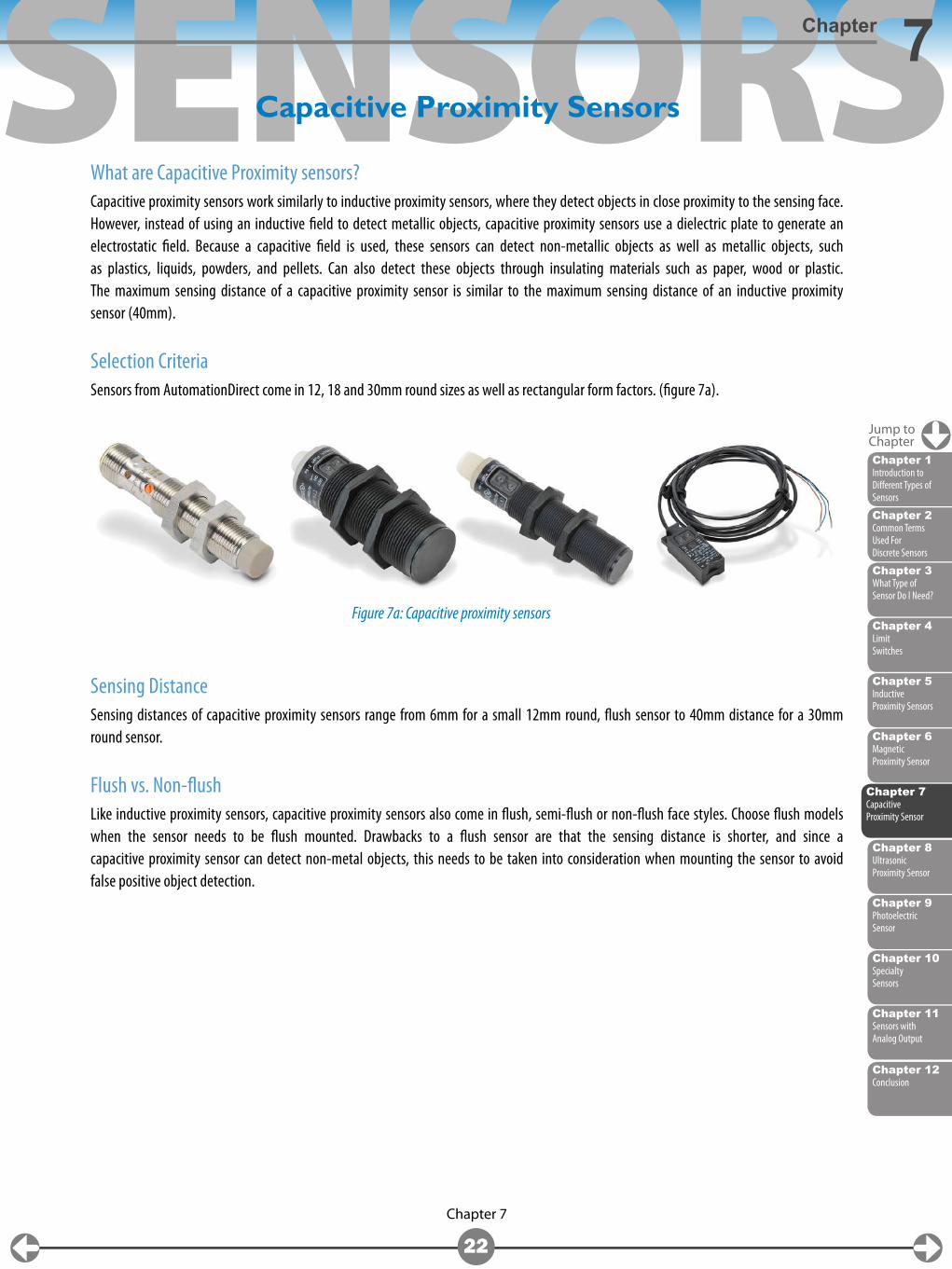
Selection CriteriaSensors from AutomationDirect come in 12, 18 and 30mm round sizes as well as rectangular form factors. (figure 7a).
Sensing DistanceSensing distances of capacitive proximity sensors range from 6mm for a small 12mm round, flush sensor to 40mm distance for a 30mm round sensor.
Flush vs. Non-flushLike inductive proximity sensors, capacitive proximity sensors also come in flush, semi-flush or non-flush face styles. Choose flush models when the sensor needs to be flush mounted. Drawbacks to a flush sensor are that the sensing distance is shorter, and since a capacitive proximity sensor can detect non-metal objects, this needs to be taken into consideration when mounting the sensor to avoid false positive object detection.
Capacitive Proximity Sensors
Figure 7a: Capacitive proximity sensors
Jump toChapter
Chapter 7Capacitive Proximity Sensor
SENSORS
Chapter 12Conclusion
Chapter 7
23
Capacitive Proximity SensorsChapter 7
Other Selection Considerations
Some capacitive proximity sensor outputs are configurable to work as a normally open or normally closed output; NPN or PNP configuration can sometimes also be determined by wiring arrangement.
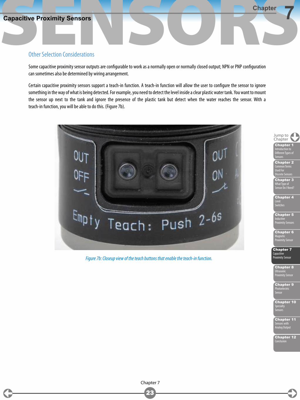
Certain capacitive proximity sensors support a teach-in function. A teach-in function will allow the user to configure the sensor to ignore something in the way of what is being detected. For example, you need to detect the level inside a clear plastic water tank. You want to mount the sensor up next to the tank and ignore the presence of the plastic tank but detect when the water reaches the sensor. With a teach-in function, you will be able to do this. (Figure 7b).
Figure 7b: Closeup view of the teach buttons that enable the teach-in function.
Jump toChapter
Chapter 2Common Terms Used For Discrete Sensors
Chapter 6Magnetic Proximity Sensor
Chapter 4Limit Switches
Chapter 9Photoelectric Sensor
Chapter 3What Type of Sensor Do I Need?
Chapter 8Ultrasonic Proximity Sensor
Chapter 11Sensors with Analog Output
Chapter 5Inductive Proximity Sensors
Chapter 10Specialty Sensors
Chapter 1Introduction to Different Types of Sensors
Chapter 7Capacitive Proximity Sensor
SENSORS
Chapter 2Common Terms Used For Discrete Sensors
Chapter 6Magnetic Proximity Sensor
Chapter 4Limit Switches
Chapter 9Photoelectric Sensor
Chapter 3What Type of Sensor Do I Need?
Chapter 11Sensors with Analog Output
Chapter 5Inductive Proximity Sensors
Chapter 10Specialty Sensors
Chapter 7Capacitive Proximity Sensor
Chapter 1Introduction to Different Types of Sensors
Chapter 12Conclusion
Chapter 8
24
Chapter 8
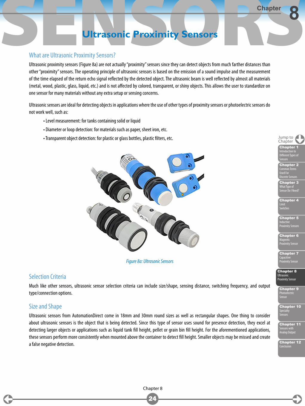
What are Ultrasonic Proximity Sensors?Ultrasonic proximity sensors (Figure 8a) are not actually “proximity” sensors since they can detect objects from much farther distances than other “proximity” sensors. The operating principle of ultrasonic sensors is based on the emission of a sound impulse and the measurement of the time elapsed of the return echo signal reflected by the detected object. The ultrasonic beam is well reflected by almost all materials (metal, wood, plastic, glass, liquid, etc.) and is not affected by colored, transparent, or shiny objects. This allows the user to standardize on one sensor for many materials without any extra setup or sensing concerns.
Ultrasonic sensors are ideal for detecting objects in applications where the use of other types of proximity sensors or photoelectric sensors do not work well, such as:
• Level measurement: for tanks containing solid or liquid
• Diameter or loop detection: for materials such as paper, sheet iron, etc.
• Transparent object detection: for plastic or glass bottles, plastic filters, etc.
Selection CriteriaMuch like other sensors, ultrasonic sensor selection criteria can include size/shape, sensing distance, switching frequency, and output type/connection options.
Size and ShapeUltrasonic sensors from AutomationDirect come in 18mm and 30mm round sizes as well as rectangular shapes. One thing to consider about ultrasonic sensors is the object that is being detected. Since this type of sensor uses sound for presence detection, they excel at detecting larger objects or applications such as liquid tank fill height, pellet or grain bin fill height. For the aforementioned applications, these sensors perform more consistently when mounted above the container to detect fill height. Smaller objects may be missed and create a false negative detection.
Ultrasonic Proximity Sensors
Figure 8a: Ultrasonic Sensors
Jump toChapter
Chapter 8Ultrasonic Proximity Sensor
SENSORS
Chapter 12Conclusion
Chapter 8
25
Ultrasonic Proximity SensorsChapter 8
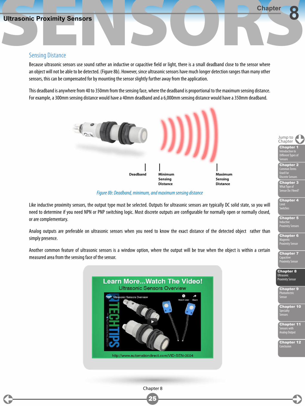
Sensing DistanceBecause ultrasonic sensors use sound rather an inductive or capacitive field or light, there is a small deadband close to the sensor where an object will not be able to be detected. (Figure 8b). However, since ultrasonic sensors have much longer detection ranges than many other sensors, this can be compensated for by mounting the sensor slightly further away from the application.
This deadband is anywhere from 40 to 350mm from the sensing face, where the deadband is proportional to the maximum sensing distance. For example, a 300mm sensing distance would have a 40mm deadband and a 6,000mm sensing distance would have a 350mm deadband.
Like inductive proximity sensors, the output type must be selected. Outputs for ultrasonic sensors are typically DC solid state, so you will need to determine if you need NPN or PNP switching logic. Most discrete outputs are configurable for normally open or normally closed, or are complementary.
Analog outputs are preferable on ultrasonic sensors when you need to know the exact distance of the detected object rather than simply presence.
Another common feature of ultrasonic sensors is a window option, where the output will be true when the object is within a certain measured area from the sensing face of the sensor.
Figure 8b: Deadband, minimum, and maximum sensing distance
Jump toChapter
Chapter 2Common Terms Used For Discrete Sensors
Chapter 6Magnetic Proximity Sensor
Chapter 4Limit Switches
Chapter 9Photoelectric Sensor
Chapter 3What Type of Sensor Do I Need?
Chapter 11Sensors with Analog Output
Chapter 5Inductive Proximity Sensors
Chapter 10Specialty Sensors
Chapter 7Capacitive Proximity Sensor
Chapter 1Introduction to Different Types of Sensors
Chapter 8Ultrasonic Proximity Sensor
SENSORS
Chapter 2Common Terms Used For Discrete Sensors
Chapter 6Magnetic Proximity Sensor
Chapter 4Limit Switches
Chapter 3What Type of Sensor Do I Need?
Chapter 8Ultrasonic Proximity Sensor
Chapter 11Sensors with Analog Output
Chapter 5Inductive Proximity Sensors
Chapter 10Specialty Sensors
Chapter 7Capacitive Proximity Sensor
Chapter 1Introduction to Different Types of Sensors
Chapter 12Conclusion
Chapter 9
26
Chapter 9
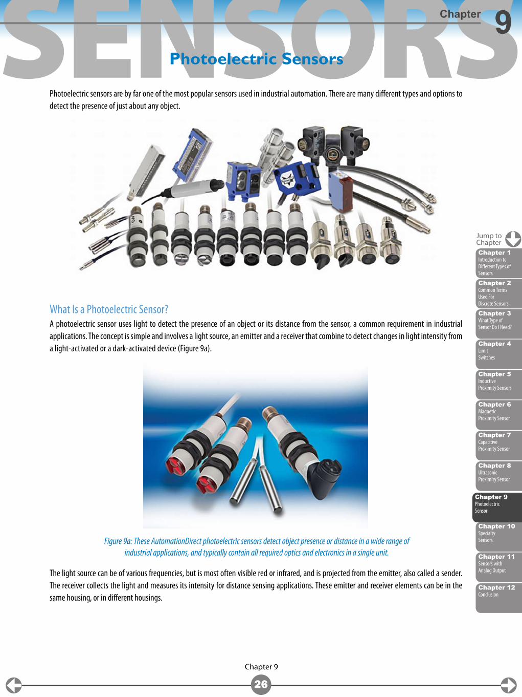
Photoelectric sensors are by far one of the most popular sensors used in industrial automation. There are many different types and options to detect the presence of just about any object.
What Is a Photoelectric Sensor?A photoelectric sensor uses light to detect the presence of an object or its distance from the sensor, a common requirement in industrial applications. The concept is simple and involves a light source, an emitter and a receiver that combine to detect changes in light intensity from a light-activated or a dark-activated device (Figure 9a).
The light source can be of various frequencies, but is most often visible red or infrared, and is projected from the emitter, also called a sender. The receiver collects the light and measures its intensity for distance sensing applications. These emitter and receiver elements can be in the same housing, or in different housings.
Photoelectric Sensors
Figure 9a: These AutomationDirect photoelectric sensors detect object presence or distance in a wide range of industrial applications, and typically contain all required optics and electronics in a single unit.
Jump toChapter
Chapter 9Photoelectric Sensor
SENSORS
Chapter 12Conclusion
Chapter 9
27
Photoelectric SensorsChapter 9
Sensing StylesThe three sensing configurations available with the photoelectric emitter and receiver in the same housing are diffuse, diffuse with background suppression and retroreflective. Diffuse/diffuse with background suppression sensing uses a sensor head with an integrated emitter and receiver. The emitted light is bounced off an object and back to the receiver. An advantage of this configuration is that there is just one sensor to mount. Disadvantages are that the sensing distance is shorter than a reflective style or through-beam sensor pair. Also, dark-colored objects may sometimes provide false negative detections if adequate light is not reflected from the object (remember, darker objects reflect less light, lighter colored objects reflect more light).
Diffuse with background suppression is a specialized diffuse photoelectric sensor that allows you to “teach” the sensor to ignore objects in the background. This adds more time to the overall setup and decreases the sensing distance, but provides more accuracy and fewer false positive detections.
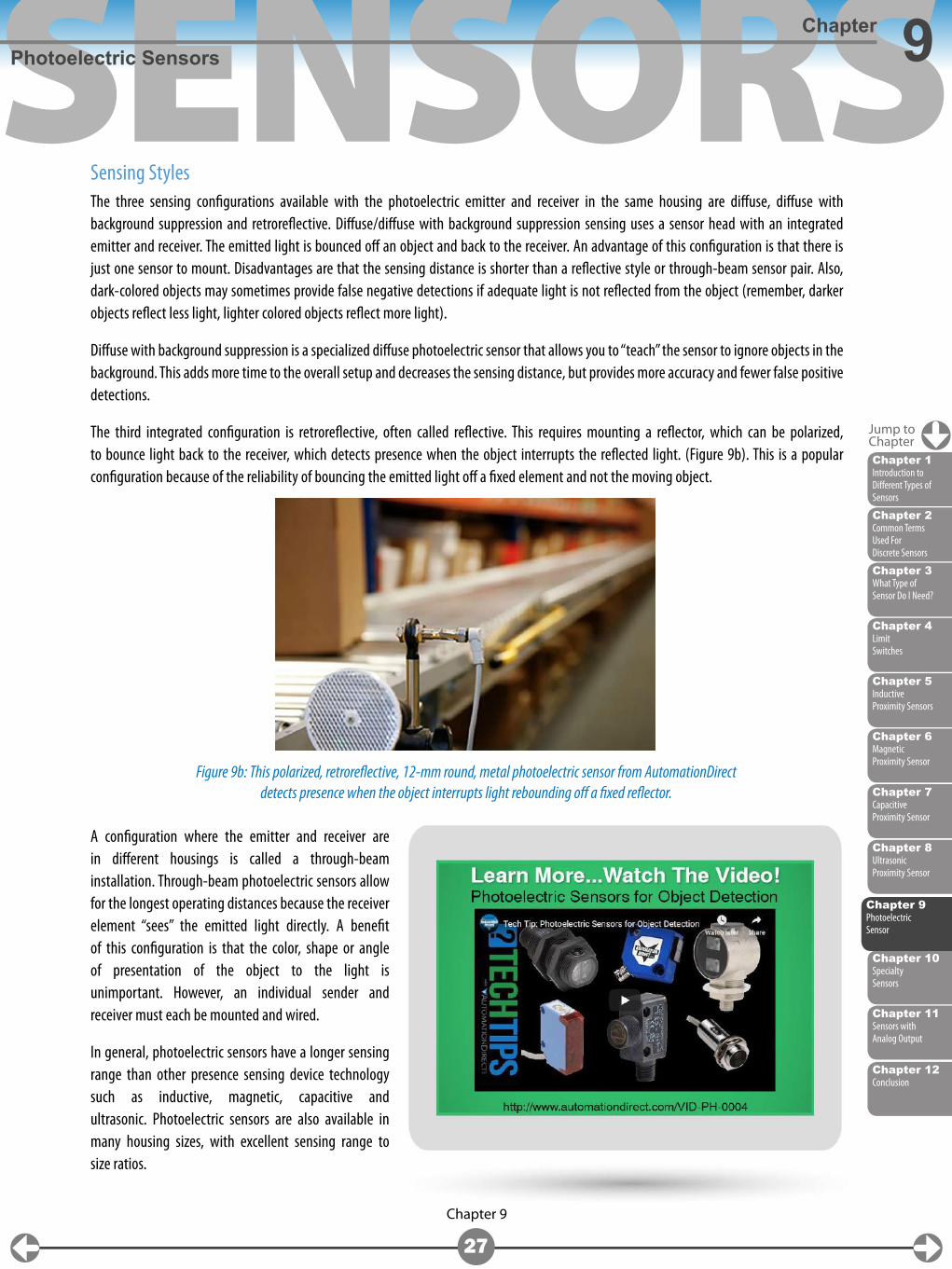
The third integrated configuration is retroreflective, often called reflective. This requires mounting a reflector, which can be polarized, to bounce light back to the receiver, which detects presence when the object interrupts the reflected light. (Figure 9b). This is a popular configuration because of the reliability of bouncing the emitted light off a fixed element and not the moving object.
A configuration where the emitter and receiver are in different housings is called a through-beam installation. Through-beam photoelectric sensors allow for the longest operating distances because the receiver element “sees” the emitted light directly. A benefit of this configuration is that the color, shape or angle of presentation of the object to the light is unimportant. However, an individual sender and receiver must each be mounted and wired.
In general, photoelectric sensors have a longer sensing range than other presence sensing device technology such as inductive, magnetic, capacitive and ultrasonic. Photoelectric sensors are also available in many housing sizes, with excellent sensing range to size ratios.
Figure 9b: This polarized, retroreflective, 12-mm round, metal photoelectric sensor from AutomationDirect detects presence when the object interrupts light rebounding off a fixed reflector.
Jump toChapter
Chapter 2Common Terms Used For Discrete Sensors
Chapter 6Magnetic Proximity Sensor
Chapter 4Limit Switches
Chapter 3What Type of Sensor Do I Need?
Chapter 8Ultrasonic Proximity Sensor
Chapter 11Sensors with Analog Output
Chapter 5Inductive Proximity Sensors
Chapter 10Specialty Sensors
Chapter 7Capacitive Proximity Sensor
Chapter 1Introduction to Different Types of Sensors
Chapter 9Photoelectric Sensor
SENSORS
Chapter 12Conclusion
Chapter 9
28
Photoelectric SensorsChapter 9
Other Selection Considerations for Photoelectric SensorsExactly how the light is sent and received can vary. In most cases, the sender will just transmit light of a certain wavelength using an LED, and the receiver will sense the light using a photo-transistor, and then energize an output. To avoid interference from ambient lighting, some sensors will pulse the light, or filter the receiver to only sense a specific wavelength.
When a reflector is used, adding a polarizing filter rotates the light 90 degrees. This phase shift allows only a preconfigured phase angle to be reflected to the receiver, helping to eliminate false detection of an object similar to the reflector.
Adjusting or programming photoelectric sensors essentially changes the threshold of light required to energize the sensing element. The type of object being detected can significantly change the threshold for proper operation. For example, a diffuse sensor might be used to detect a dark colored object one meter away. A powerful light emission source is necessary because when the light bounces off the object, much of it is absorbed by the dark surface, returning little light. The threshold to detect this dark object would be very different from the threshold to detect a white object at the same distance.
The detection distance can also greatly affect the threshold. When detecting objects at only one centimeter away, whether dark or light, there will be much more light reflected back to the receiver due to the short travel distance as compared to longer distances.
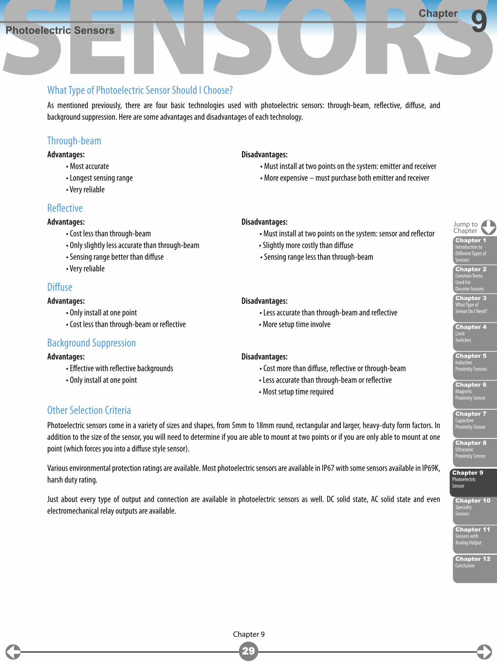
To combat the effect of color of dark and light objects, some sensors monitor the angle of the light bouncing back (Figure 9c). This is only found in diffuse applications and can be used to determine the distance of the object from the sensor. Instead of looking at the intensity of the light reflected as with a conventional distance sensor, an array of receiving elements are used. Depending on which element sees the light, the sensor can “triangulate” the distance to the object.
Figure 9c: A diffuse photoelectric sensor uses a sensor head with integrated emitter and receiver, with emitted light reflecting from the target object back to the sensor.
Jump toChapter
Chapter 2Common Terms Used For Discrete Sensors
Chapter 6Magnetic Proximity Sensor
Chapter 4Limit Switches
Chapter 3What Type of Sensor Do I Need?
Chapter 8Ultrasonic Proximity Sensor
Chapter 11Sensors with Analog Output
Chapter 5Inductive Proximity Sensors
Chapter 10Specialty Sensors
Chapter 7Capacitive Proximity Sensor
Chapter 1Introduction to Different Types of Sensors
Chapter 9Photoelectric Sensor
SENSORS
Chapter 12Conclusion
Chapter 9
29
Photoelectric SensorsChapter 9
What Type of Photoelectric Sensor Should I Choose?As mentioned previously, there are four basic technologies used with photoelectric sensors: through-beam, reflective, diffuse, and background suppression. Here are some advantages and disadvantages of each technology.
Through-beamAdvantages: Disadvantages: • Most accurate • Must install at two points on the system: emitter and receiver • Longest sensing range • More expensive – must purchase both emitter and receiver • Very reliable
ReflectiveAdvantages: Disadvantages: • Cost less than through-beam • Must install at two points on the system: sensor and reflector • Only slightly less accurate than through-beam • Slightly more costly than diffuse • Sensing range better than diffuse • Sensing range less than through-beam • Very reliable
DiffuseAdvantages: Disadvantages: • Only install at one point • Less accurate than through-beam and reflective • Cost less than through-beam or reflective • More setup time involve
Background SuppressionAdvantages: Disadvantages: • Effective with reflective backgrounds • Cost more than diffuse, reflective or through-beam • Only install at one point • Less accurate than through-beam or reflective • Most setup time required
Other Selection CriteriaPhotoelectric sensors come in a variety of sizes and shapes, from 5mm to 18mm round, rectangular and larger, heavy-duty form factors. In addition to the size of the sensor, you will need to determine if you are able to mount at two points or if you are only able to mount at one point (which forces you into a diffuse style sensor).
Various environmental protection ratings are available. Most photoelectric sensors are available in IP67 with some sensors available in IP69K, harsh duty rating.
Just about every type of output and connection are available in photoelectric sensors as well. DC solid state, AC solid state and even electromechanical relay outputs are available.
Jump toChapter
Chapter 2Common Terms Used For Discrete Sensors
Chapter 6Magnetic Proximity Sensor
Chapter 4Limit Switches
Chapter 3What Type of Sensor Do I Need?
Chapter 8Ultrasonic Proximity Sensor
Chapter 11Sensors with Analog Output
Chapter 5Inductive Proximity Sensors
Chapter 10Specialty Sensors
Chapter 7Capacitive Proximity Sensor
Chapter 1Introduction to Different Types of Sensors
Chapter 9Photoelectric Sensor
SENSORS
30
Jump toChapter
Chapter 10
Chapter 10
Chapter 2Common Terms Used For Discrete Sensors
Chapter 6Magnetic Proximity Sensor
Chapter 4Limit Switches
Chapter 9Photoelectric Sensor
Chapter 3What Type of Sensor Do I Need?
Chapter 8Ultrasonic Proximity Sensor
Chapter 11Sensors with Analog Output
Chapter 5Inductive Proximity Sensors
Chapter 7Capacitive Proximity Sensor
Chapter 1Introduction to Different Types of Sensors
Chapter 12Conclusion
Specialty Sensors: Laser Sensors, Fiber Optic Sensors, Fork Sensors, and Area Sensors
In addition to traditional photoelectric sensors, there are several other specialty sensors that use technology similar to photoelectric sensors to detect an object.
Some of the types of specialty sensors mentioned in this chapter are laser sensors, fiber optic sensors, fork sensors, and area sensors. All of these sensors use photoelectric technology of some type to detect objects.
Laser SensorsLaser sensors use highly focused laser light to detect objects or measure distances and can return a measured value regardless of ambient light, or the object’s material, color or brightness. Laser sensors are available in diffuse, background suppression and retroreflective styles for object presence, or with CMOS or transit time technologies for accurate distance measuring.
The reasons you would choose a laser sensor over traditional photoelectric technology are the need for a much farther sensing distance, and a requirement for greater accuracy (smaller object is to be detected or the tolerance of the application requires greater accuracy).
There are two types of lasers used in this sensor category. Class 1 lasers are eye-safe under all operating conditions. Class 2 lasers are visible lasers safe for quick accidental viewing of less than 0.25 s but may damage the eye if deliberately stared into. One reason you would choose the more dangerous class 2 laser would be that the laser is visible and would aid in focusing/aligning the beam on the object to be detected/measured.
Laser sensors have exceptional resolution over standard photoelectric sensors and are available in diffuse, background suppression and retroreflective styles. In addition to better resolution, laser sensors offer much longer sensing distances, from 3 meters for a background suppression model, 10 meters for a model, all the way up to 100 meter sensing distance for the most advanced retroreflective models.
Chapter 10Specialty Sensors
SENSORS
31 Chapter 10
Specialty Sensors: Laser Sensors, Fiber Optic Sensors, Fork Sensors, Area SensorsChapter 10
Jump toChapter
Chapter 12Conclusion
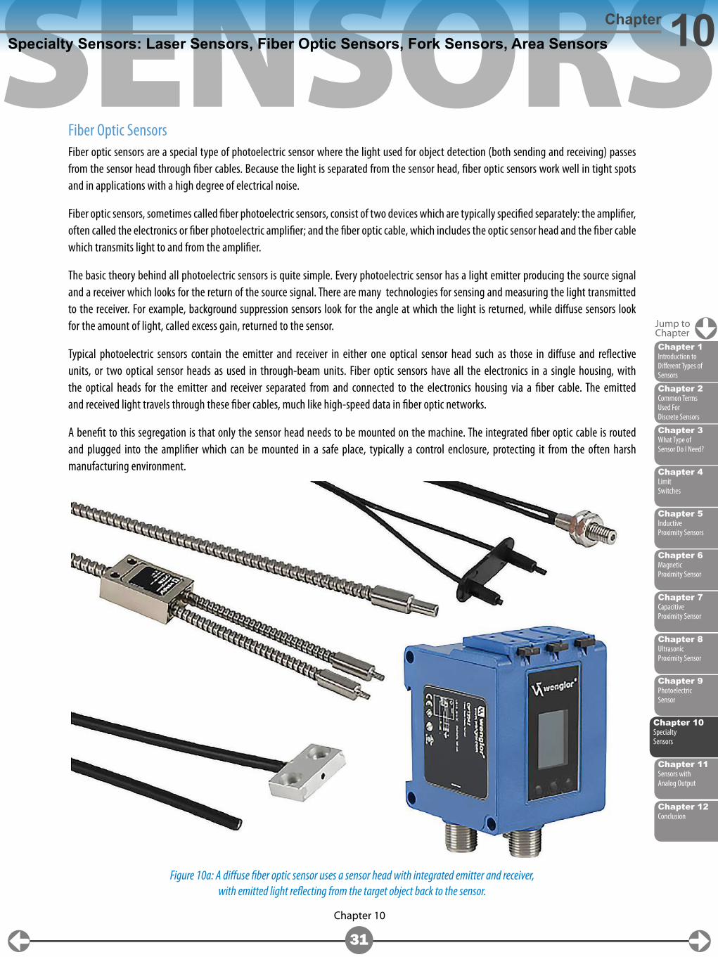
Fiber Optic SensorsFiber optic sensors are a special type of photoelectric sensor where the light used for object detection (both sending and receiving) passes from the sensor head through fiber cables. Because the light is separated from the sensor head, fiber optic sensors work well in tight spots and in applications with a high degree of electrical noise.
Fiber optic sensors, sometimes called fiber photoelectric sensors, consist of two devices which are typically specified separately: the amplifier, often called the electronics or fiber photoelectric amplifier; and the fiber optic cable, which includes the optic sensor head and the fiber cable which transmits light to and from the amplifier.
The basic theory behind all photoelectric sensors is quite simple. Every photoelectric sensor has a light emitter producing the source signal and a receiver which looks for the return of the source signal. There are many technologies for sensing and measuring the light transmitted to the receiver. For example, background suppression sensors look for the angle at which the light is returned, while diffuse sensors look for the amount of light, called excess gain, returned to the sensor.
Typical photoelectric sensors contain the emitter and receiver in either one optical sensor head such as those in diffuse and reflective units, or two optical sensor heads as used in through-beam units. Fiber optic sensors have all the electronics in a single housing, with the optical heads for the emitter and receiver separated from and connected to the electronics housing via a fiber cable. The emitted and received light travels through these fiber cables, much like high-speed data in fiber optic networks.
A benefit to this segregation is that only the sensor head needs to be mounted on the machine. The integrated fiber optic cable is routed and plugged into the amplifier which can be mounted in a safe place, typically a control enclosure, protecting it from the often harsh manufacturing environment.
Figure 10a: A diffuse fiber optic sensor uses a sensor head with integrated emitter and receiver, with emitted light reflecting from the target object back to the sensor.
Chapter 2Common Terms Used For Discrete Sensors
Chapter 6Magnetic Proximity Sensor
Chapter 4Limit Switches
Chapter 9Photoelectric Sensor
Chapter 3What Type of Sensor Do I Need?
Chapter 8Ultrasonic Proximity Sensor
Chapter 11Sensors with Analog Output
Chapter 5Inductive Proximity Sensors
Chapter 7Capacitive Proximity Sensor
Chapter 1Introduction to Different Types of Sensors
Chapter 10Specialty Sensors
SENSORS
32 Chapter 10
Specialty Sensors: Laser Sensors, Fiber Optic Sensors, Fork Sensors, Area SensorsChapter 10
Jump toChapter
Chapter 12Conclusion
Fiber optics work well and are commonly used in applications where there is significant electrical noise generated by such sources as automated welding, variable frequency drives, and motors. Fiber cabling is immune to electrical noise, and the electronics can be mounted away from the noise in a shielded enclosure.
Another very common application is small part assembly. These operations tend to be fully automated and thus require multiple sensors to confirm part placement (seated), and assembly verification to confirm an operation was completed. Typically, the parts are moving in and out of a stage quickly on carriers or an indexing table. There is minimal travel tolerance, so precise measurement of position is essential.
Fork (Slot) Sensors Fork sensors are a highly specialized type of through-beam photoelectric sensors. The emitter and receiver are integrated into the same housing; the two components are set in a fixed fashion on either side of a fork-shaped fixture.
The fixed-opening is used to detect small objects passing through the slot in the fork. These types of sensors are used on machines when a small object, such as a bolt, needs to be detected. The sensing slot on these is rather small, ranging from 5 to 220mm. Light sources are typically infrared, or visible red light if there is a need to verify the correct position of the sensing light beam.
Chapter 2Common Terms Used For Discrete Sensors
Chapter 6Magnetic Proximity Sensor
Chapter 4Limit Switches
Chapter 9Photoelectric Sensor
Chapter 3What Type of Sensor Do I Need?
Chapter 8Ultrasonic Proximity Sensor
Chapter 11Sensors with Analog Output
Chapter 5Inductive Proximity Sensors
Chapter 7Capacitive Proximity Sensor
Chapter 1Introduction to Different Types of Sensors
Chapter 10Specialty Sensors
SENSORS
33 Chapter 10
Specialty Sensors: Laser Sensors, Fiber Optic Sensors, Fork Sensors, Area SensorsChapter 10
Jump toChapter
Chapter 12Conclusion
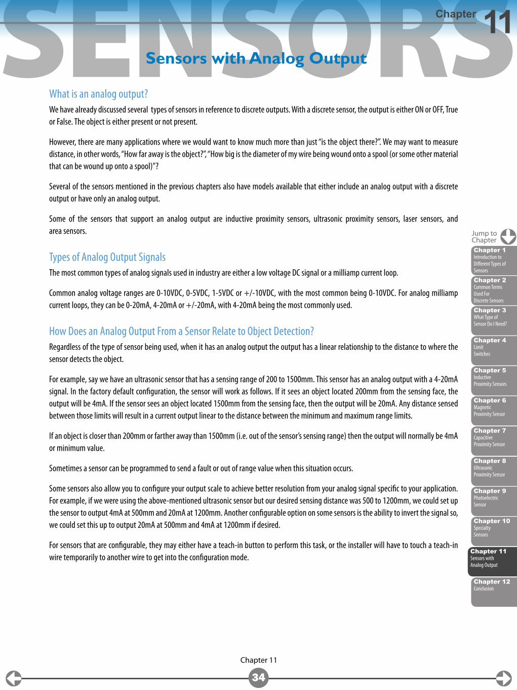
Area SensorsArea sensors are a multi-beam array of photoelectric sensors. These sensors provide a simple method to detect different sized and shaped objects as they drop or pass through the two-dimensional target area.
Think of a safety light curtain, but instead of detecting someone’s hand going through the light beam array and shutting a machine down, we are detecting the presence of an object in the light beam array. Keep in mind that area sensors are NOT safety devices and cannot be used in place of a safety light curtain.
The distance between the light beams in the array is known as the pitch, which determines the minimum object size that can be detected. The pitch varies from 5 to 10mm which translates to a minimum object detection size range of 1.5 to 10mm in height.
The area sensor array height can range from 70 to nearly 1000mm so any time an object is anywhere inside of this array, the sensor will detect an object’s presence.
The output of an area sensor can be discrete or include an analog output.
Some common applications include error-proofing the dropping of a part into a reject bin, where any time an object passes through the array, the discrete output will signal an object has been detected. An application example for an area sensor with an analog output would be using the sensor to detect approximate case height of cases or boxes traveling on a conveyor.
Chapter 2Common Terms Used For Discrete Sensors
Chapter 6Magnetic Proximity Sensor
Chapter 4Limit Switches
Chapter 9Photoelectric Sensor
Chapter 3What Type of Sensor Do I Need?
Chapter 8Ultrasonic Proximity Sensor
Chapter 11Sensors with Analog Output
Chapter 5Inductive Proximity Sensors
Chapter 7Capacitive Proximity Sensor
Chapter 1Introduction to Different Types of Sensors
Chapter 10Specialty Sensors
SENSORS
Chapter 11
34
Chapter 11
Jump toChapter
Chapter 11Sensors with Analog Output
Chapter 2Common Terms Used For Discrete Sensors
Chapter 6Magnetic Proximity Sensor
Chapter 4Limit Switches
Chapter 9Photoelectric Sensor
Chapter 3What Type of Sensor Do I Need?
Chapter 8Ultrasonic Proximity Sensor
Chapter 5Inductive Proximity Sensors
Chapter 10Specialty Sensors
Chapter 7Capacitive Proximity Sensor
Chapter 1Introduction to Different Types of Sensors
Chapter 12Conclusion
Sensors with Analog Output
What is an analog output?We have already discussed several types of sensors in reference to discrete outputs. With a discrete sensor, the output is either ON or OFF, True or False. The object is either present or not present.
However, there are many applications where we would want to know much more than just “is the object there?”. We may want to measure distance, in other words, “How far away is the object?”, “How big is the diameter of my wire being wound onto a spool (or some other material that can be wound up onto a spool)”?
Several of the sensors mentioned in the previous chapters also have models available that either include an analog output with a discrete output or have only an analog output.
Some of the sensors that support an analog output are inductive proximity sensors, ultrasonic proximity sensors, laser sensors, and area sensors.
Types of Analog Output SignalsThe most common types of analog signals used in industry are either a low voltage DC signal or a milliamp current loop.
Common analog voltage ranges are 0-10VDC, 0-5VDC, 1-5VDC or +/-10VDC, with the most common being 0-10VDC. For analog milliamp current loops, they can be 0-20mA, 4-20mA or +/-20mA, with 4-20mA being the most commonly used.
How Does an Analog Output From a Sensor Relate to Object Detection?Regardless of the type of sensor being used, when it has an analog output the output has a linear relationship to the distance to where the sensor detects the object.
For example, say we have an ultrasonic sensor that has a sensing range of 200 to 1500mm. This sensor has an analog output with a 4-20mA signal. In the factory default configuration, the sensor will work as follows. If it sees an object located 200mm from the sensing face, the output will be 4mA. If the sensor sees an object located 1500mm from the sensing face, then the output will be 20mA. Any distance sensed between those limits will result in a current output linear to the distance between the minimum and maximum range limits.
If an object is closer than 200mm or farther away than 1500mm (i.e. out of the sensor’s sensing range) then the output will normally be 4mA or minimum value.
Sometimes a sensor can be programmed to send a fault or out of range value when this situation occurs.
Some sensors also allow you to configure your output scale to achieve better resolution from your analog signal specific to your application. For example, if we were using the above-mentioned ultrasonic sensor but our desired sensing distance was 500 to 1200mm, we could set up the sensor to output 4mA at 500mm and 20mA at 1200mm. Another configurable option on some sensors is the ability to invert the signal so, we could set this up to output 20mA at 500mm and 4mA at 1200mm if desired.
For sensors that are configurable, they may either have a teach-in button to perform this task, or the installer will have to touch a teach-in wire temporarily to another wire to get into the configuration mode.
SENSORS
Chapter 11
35
Sensors with Analog OutputChapter 11
Jump toChapter
Chapter 11Sensors with Analog Output
Chapter 2Common Terms Used For Discrete Sensors
Chapter 6Magnetic Proximity Sensor
Chapter 4Limit Switches
Chapter 9Photoelectric Sensor
Chapter 3What Type of Sensor Do I Need?
Chapter 8Ultrasonic Proximity Sensor
Chapter 5Inductive Proximity Sensors
Chapter 10Specialty Sensors
Chapter 7Capacitive Proximity Sensor
Chapter 1Introduction to Different Types of Sensors
Chapter 12Conclusion
Types of Sensors That Support an Analog OutputSome inductive proximity sensors have an analog output in lieu of a discrete output. These sensors still follow the same rules as their discrete counterparts where they can only detect metallic objects at a very close distance, and output a value from 4-20mA. The analog signal will provide a more accurate depiction of how close or far away the metallic object is from the face of the sensor as opposed to “the object is there”.
Ultrasonic sensors that have an analog output provide much longer ranges of distance measurement than inductive proximity sensors. There is almost always a deadband close to the sensor face. The deadband is larger as the sensing distance increases. Some of the nicer features of ultrasonic sensors with analog outputs, in addition to their sensing distance, are their configuration options. The signal can be adjusted to fit the application and can even be inverted. Ultrasonic sensors can be purchased with an analog output only; there are models available that have an analog and discrete output together in the same sensor.
Laser sensors are primarily used for distance measurement due to their longer sensing distance and accuracy. Laser sensors that include an analog output feature excellent configuration flexibility by allowing selection of the output scale based on the application’s sensing range, signal inversion, and an optional discrete output. Laser sensors allow you to be able to measure the distance of an object all the way up to 100 meters away.
Some advanced area sensors include an analog output as well. With area sensors, the analog output signal is proportional to the number of beams blocked. The higher the output signal, the more beams are blocked. This is useful to be able to get an approximate height or length of an object passing through the area sensor beam array.
SENSORS
Chapter 12
36
Chapter 12
Jump toChapter
Chapter 12Conclusion
Chapter 2Common Terms Used For Discrete Sensors
Chapter 6Magnetic Proximity Sensor
Chapter 4Limit Switches
Chapter 9Photoelectric Sensor
Chapter 3What Type of Sensor Do I Need?
Chapter 8Ultrasonic Proximity Sensor
Chapter 5Inductive Proximity Sensors
Chapter 10Specialty Sensors
Chapter 7Capacitive Proximity Sensor
Chapter 1Introduction to Different Types of Sensors
Conclusion
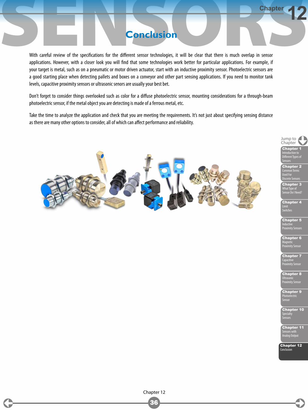
With careful review of the specifications for the different sensor technologies, it will be clear that there is much overlap in sensor applications. However, with a closer look you will find that some technologies work better for particular applications. For example, if your target is metal, such as on a pneumatic or motor driven actuator, start with an inductive proximity sensor. Photoelectric sensors are a good starting place when detecting pallets and boxes on a conveyor and other part sensing applications. If you need to monitor tank levels, capacitive proximity sensors or ultrasonic senors are usually your best bet.
Don’t forget to consider things overlooked such as color for a diffuse photoelectric sensor, mounting considerations for a through-beam photoelectric sensor, if the metal object you are detecting is made of a ferrous metal, etc.
Take the time to analyze the application and check that you are meeting the requirements. It’s not just about specifying sensing distance as there are many other options to consider, all of which can affect performance and reliability.
Chapter 11Sensors with Analog Output