Embed Size (px)
Citation preview

2
3
4
1
5
6
7
8
s
Products and Applications
Sonar-BERO
Opto-BERO
Inductive BERO
Capacitive BERO
Accessories
Supplementary Components – MOBY
Appendix
Contact your local Siemens representative for further information
The products in this catalog are also included in the CD-ROM catalog CA 01Order No.: E86060-D4001-A100-B6-7600
Sensors forAutomation
Catalog NS BERO · 2001/02
BERO
The products and systems described in this catalog are manufactured under applica-tion of a quality management system certified by DQS in accordance with ISO 9001 (Certificate Registration No.: 019634-01).The DQS Certificate is recog-nized in all EQ Net countries.
© Siemens AG 2001

1/4 Siemens NS BERO · 2001/02
Products and Applications
Sonar-BERO
Field of applicationThe wide range of applications for Sonar-BERO ultrasonic sen-sors is limited only by the de-signer’s imagination:• Level and height sensing• Distance measurement• Winding diameter detection• Bottle counting and much
moreThe sonar technology of the Sonar-BERO sensors enables them to detect any type of ob-ject, including liquids and pow-ders and colored or transparent objects.They also respond regardless of surface character or condition: rough or smooth, wet or dry, clean or soiled.
Sonar-BERO sensors are also extremely rugged and their operation is insensitive to dirt, vibration, ambient light and ambient sound.The Sonar-BERO measures the time taken for the emitted ultra-sonic pulse to return following reflection by the object, from which it can calculate the dis-tance to the object. The Sonar-BERO can operate over ex-tremely short distances (6 cm) or extremely long distances (10 m) without any problems at all.The SONPROG software makes it easy to make adjustments for the object and the operating range (e. g. minimum level).
Application:Level measurement in large containers
Sensor:Compact form K 65 with minimum/maximum monitoring (up to 2.5 m)Compact range M 18 with analog output (up to 1 m)Compact range III (up to 6 m)
Application:Measuring stack height
Sensor:Compact range M 18 with analog output (up to 1 m)Compact range III (up to 6 m)
Application:Level measurement in small bottles
Sensor:Compact range M 18 with analog output
Application:Diameter detection and speed measurement
Sensor:Compact range M 18 with analog output (up to 1 m)Compact range III (up to 6 m)
Application:Size measurement
Sensor:Compact range M 18 with analog output (up to 1 m)Compact range III (up to 6 m)
Application:Contour recognition
Sensor:Compact range M 18 with analog output (up to 1 m)Compact range III (up to 6 m)Synchronization

Products and Applications
Sonar-BERO
1/5Siemens NS BERO · 2001/02
1
Field of application
Application:Loop monitoring
Sensor:Compact form K 65 with minimum/maximum monitoring (up to 2.5 m)Compact range II with 2 switching outputs
Application:Quality control
Sensor:Compact range M 18 with switching outputCompact range II (up to 6 m)
Application:Bottle counting and gap recognition
Sensor:Sonar thru-beam sensor
Application:Breakage monitoring
Sensor:Compact range M 18 with switching output (up to 30 cm)
Application:Object detection
Sensor:Compact range M 18 with switching output
Application:Wire and cable break monitoring
Sensor:Compact range M 18 with switching outputCompact range II
Application:Gap monitoring
Sensor:Compact range II with 2 switching outputs (up to 6 m)

1/6 Siemens NS BERO · 2001/02
Products and Applications
Opto-BERO
Field of applicationOpto-BERO sensors are used in their various designs as• Diffuse sensors• Thru-beam sensors or• Retroreflective sensors– either with background suppression or as fiber-optic devices – especially in the fol-lowing applications:• In conveyor systems • In mechanical engineering • In paper, textile and plastics
processing• In printing presses and• In packaging machines.The comprehensive range of Opto-BEROs operates using in-frared light, red light or laser light and covers ranges of be-tween 3 cm and 50 m. These photoelectric sensors can de-tect any object whether it is
made of metal, wood or plastic. Even transparent objects can be detected by Opto-BERO K 20 in the miniature housing.Special devices, such as the color sensor or color mark sen-sor, can be used to recognize different colors or contrast differences. The analog laser supports extremely precise level measurement and position monitoring.The Opto-BEROs are easily ad-justed using teach-in functions or potentiometers. A wide selec-tion of cubic, cylindrical and miniature types satisfies the de-signer's every wish.
Application:Inspection of the content of transparent containers
Sensor:M 12 thru-beam sensor
Application:Recognition of loaded pallets
Sensor:K 31 retroreflective sensor with polarized red light
Application:Recognition of tins of food on a conveyor belt
Sensor:K 50 retroreflective sensor with polarized red light
Application:Bottle counting
Sensor:C 40 retroreflective sensor with polarized red light, also for clear glass recognition
Application:Recognition of boxes on a roller conveyor
Sensor:K 50 retroreflective sensor with polarized red light
Application:Entry control for a car wash-ing plant
Sensor:K 80 thru-beam sensor
Application:Recognition of color marks for triggering the cut com-mand
Sensor:C 80 color mark sensor
Application:Access monitoring
Sensor:K 50 retroreflective sensor

Products and Applications
Opto-BERO
1/7Siemens NS BERO · 2001/02
1
Field of application
Application:Monitoring of an entry barri-er
Sensor:K 80 retroreflective sensor with polarized red light
Application:Detection of the end of a roll
Sensor:K 31 light switch
Application:Thread recognition in a drilled hole
Sensor:KL 40 with plastic fiber-optic conductor
Application:Recognition of tops on bottles
Sensor:K 20 light switch with back-ground suppressionK 20 retroreflective sensor for clear glass detection
Application:Recognition of packages
Sensor:K 80 retroreflective sensor with polarized red light
Application:Recognition of objects in a container
Sensor:K 20 light sensor with back-ground suppression
Application:Position detection of ICs
Sensor:L 50 laser light sensor with background suppression
Application:Recognition of objects with different dimensions
Sensor:K 80 light sensor with back-ground suppression
Application:Position detection of ICs
Sensor:C 80 color mark sensor
Application:Inspection of stack heights
Sensor:K 80 thru-beam sensor
Application:Bottleneck detection on a roller conveyor
Sensor:K 80 retroreflective sensor with polarized red light
Application:Recognition of wrongly positioned objects on a conveyor
Sensor:C 40 retroreflective sensor

1/8 Siemens NS BERO · 2001/02
Products and Applications
Opto-BERO
Field of application
Application:Detection of IC pins
Sensor:KL 40 with plastic fiber-optic conductor
Application:Object detection on a roller conveyor
Sensor:K 40 retroreflective sensor with polarized red light
Application:Object detection for activat-ing a conveyor
Sensor:K 35 retroreflective sensor
Application:Recognition of reflecting objects
Sensor:K 80 retroreflective sensor with polarized red light
Application:Liquid inspection in glass containers
Sensor:K 35 with plastic fiber-optic conductor
Application:Checking the correct posi-tion of screws
Sensor:KL 40 with plastic fiber-optic conductor
Application:Object inspection in trans-parent packaging
Sensor:KL 40 with plastic fiber-optic conductor
Application:Checking lipstick height before fitting the cap
Sensor:M 5 or M 12 thru-beam sensor
Application:Detection of labels on a transparent backing tape
Sensor:G 20 fork/slot sensor
Application:Monitoring objects leaving a vibration conveyor
Sensor:K 35 with plastic fiber-optic conductor

Products and Applications
Inductive and capacitive BERO
1/9Siemens NS BERO · 2001/02
1
Field of applicationInductive BERO proximity sen-sors are the most economical solution for detecting metal ob-jects without contact. They are most often used where metal is the most common material, e. g.• In the automotive industry • In mechanical engineering • In the robotics industry • In conveyor systems and • In the paper and printing
industry.The induction principle and the extensive experience of Siemens over many years have made inductive BEROs what they are: Extremely reliable with a high repeat accuracy and long service life due to the lack of wear and of sensitivity to temperature, sound, light and water.Customers also benefit from the wide variety of inductive BERO proximity switches that Siemens offers. Our complete scope of products meets a wide range of
different requirements leaving nothing to be desired. There are inductive BEROs• With operating distances
ranging from 0.6 to 75 mm • In cylindrical and cubic types • In the standard duty version
as 3 and 4-wire sensors• As 2-wire sensors for solid-
state inputs (PLC)• In extra duty version (65 V DC
or 320 V AC/DC)• To the IP 68 degree of
protection for extreme environmental conditions
• With higher rated operating distances
• Without reduction factor• As pressure-proof sensors• Acc. to DESINA specification• Intrinsically safe sensors for
potentially explosive environments.
Application:Detection of broken drills
Sensor:Inductive BERO 3RG4
Application:Recognition of tins and lids
Sensor:
Inductive BERO 3RG4
Application:Recognition of position screws on a wheel for speed or direction control
Sensor:Inductive BERO 3RG4
Capacitive BEROsAs an alternative to inductive BEROs, capacitive BEROs are available that can detect non-conductive materials in solid, liquid or granular form, e. g. glass, plastic, wood, oil, water and paper.
Application:Recognition of valve posi-tion (completely open or closed)
Sensor:Inductive BERO 3RG4
Application:Detection of milk in cartons
Sensor:Capacitive BERO 3RG16
Application:Recognition of fragments on a cutter
Sensor:Inductive BERO 3RG4
Application:Level monitoring of loose material in a container
Sensor:Capacitive BERO 3RG16

Sonar-BERO 3RG6 Ultrasonic Proximity Switches
2/2 Siemens NS BERO · 2001/02
Compact ranges I, II, III with fixed, swivel and separate sensors
3RG60, 3RG61 Page
Selection and ordering data• Compact range I 2/33, 2/34• Compact range II 2/31, 2/32• Compact range III 2/29, 2/30
Introduction 2/4Sound cones 2/13 to 2/16Description 2/18Connection diagrams 2/19Technical data 2/32 to 2/37Dimension drawings 2/32 to 2/37
Compact range M 18, M 18 S Compact range 0 SONPROG interface unit
3RG62 Page 3RG63 Page 3RX4 000 Page
Selection and ordering data 2/35 Selection and ordering data 2/36 Selection and ordering data 2/35
Introduction 2/4 Introduction 2/4 Introduction 2/4Sound cones 2/11, 2/12 Sound cones 2/10 Description 2/23Description 2/20 Description 2/20 Technical data 2/23Connection diagrams 2/20 Connection diagrams 2/20Technical data 2/38 Technical data 2/39Dimension drawings 2/38 Dimension drawings 2/39

Sonar-BERO 3RG6 Ultrasonic Proximity Switches
Siemens NS BERO · 2001/02 2/3
2
Compact form Sonar thru-beam sensor Double-layer sheet monitoring
3RG62, 3SG16 Page 3RG62 Page 3RX2 210 Page
Selection and ordering data Selection and ordering data 2/39 Selection and ordering data 2/40• 3SG16 2/37• K 65 2/38
Introduction 2/4 Introduction 2/4 Introduction 2/4Sound cones 2/11 Sound cones 2/10 Description 2/27Description 2/24, 2/25 Description 2/26 Technical data 2/40Connection diagrams 2/24, 2/25 Connection diagrams 2/26 Dimension drawing 2/40Technical data 2/42, 2/43 Technical data 2/39Dimension drawings 2/42, 2/43 Dimension drawings 2/39
Modular range II
3RG61 Page
Selection and ordering data• Signal evaluator 2/41• Sensors 2/42, 2/43
Introduction 2/4Sound cones 2/13 to 2/16Description 2/28Connection diagram 2/28Time diagram 2/41Technical data 2/41 to 2/43Dimension drawings 2/41 to 2/43

2/4 Siemens NS BERO · 2001/02
Sonar-BERO 3RG6 Ultrasonic Proximity Switches
Introduction
Overview
The main technical features of each series are shown in the following table.
Com
pac
t ran
ge
0
Com
pac
t ran
ge
I
Com
pac
t ran
ge
II
Com
pac
t ran
ge
III
Com
pac
t ran
ge
M 1
8
Com
pac
t for
m 3
SG
16
Com
pac
t for
m K
65
Son
ar th
ru-b
eam
sen
sor
Mod
ular
ran
ge
II
Dou
ble
-laye
r sh
eet m
onito
ring
Mode of operationDiffuse sensor 7 7 7 7 7 7 7 7Reflex sensor 7 7 7 $ 7 7Thru-beam sensor 7 7 7 7 7Output1 switching output 7 7 7 7 72 switching outputs 7 7 7 71 switching output + 1 analog output 72 relay outputs + 1 analog output 7 71 analog output 71 frequency output 7 7Analog output0 to 20 mA 7 7 74 to 20 mA 7 7 70 to 10 V 7 7 7Setting1 potentiometer 7 72 potentiometers 7 7 7SONPROG interface unit 7 7 7 7Jumpers 7Teach-in 7 7 7 7 7Keys 7Wiring 7Parameters that can be changed with SONPROGBlind zone 7 7 7 7End of sensing range 7 7 7 7Lower limit of operating range 7 7 $ 7Upper limit of operating range 7 7 $ 7Differential travel 7 7 $ 7NO/NC switching output function 7 7 $ 7Lower limit of analog range 7 &Upper limit of analog range 7 &Analog output characteristic 7 &Analog output current range 7 &
Mean-value generation 7 7 7 7Mode of operation 7 7 7Temperature compensation 7 7 7 7Enable/disable potentiometers 7 7 $
Description 2/20 2/18 2/18 2/18 2/20 2/24 2/25 2/26 2/28 2/27Ordering data, technical data 2/36 2/33 2/31 2/29 2/35 2/37 2/38 2/39 2/41 2/40
Sonar-BERO programmable with SONPROG
7 Available$ Only available for devices with switching output& Only available for devices with analog output

Sonar-BERO 3RG6 Ultrasonic Proximity Switches
Introduction
2/5Siemens NS BERO · 2001/02
2
Field of application
The applications listed in the fol-lowing table are some of the most familiar and most frequent fields of application of the Sonar-BERO.
The device types marked as special designs feature special functions in addition to the series design.
Enquiries about special designs and continued support should be addressed to our Technical Support department. You will find information about this in the Appendix to this Catalog.
Special versions
For ordering sensors with spe-cial designs or preset param-eters, the order number must be supplemented with “–Z” and the required features should be specified in plain text.
Ordering example
Sensor of compact range II, sensing range 20 to 130 mm, 1 NO, stainless steel housing:
3RG6013–3AF00–ZZ = Stainless steel housing
Applications
Com
pac
t ran
ges
0, I
, II,
III,
M18
(sp
ecia
l des
ign)
Com
pac
t ran
ges
0, I
, II,
III,
M18
(sp
ecia
l des
ign)
Com
pac
t ran
ge
II w
ith 2
sw
itchi
ng o
utp
uts
(sp
. des
ign)
Com
pac
t ran
ge
II, M
18
(sp
ecia
l des
ign)
Com
pac
t for
m K
65
Com
pac
t ran
ge
II w
ith 2
sw
itchi
ng o
utp
uts
(sp
. des
ign)
Com
pac
t ran
ge
II w
ith
freq
uenc
y ou
tput
Com
pac
t ran
ge
II (s
pec
ial d
esig
n)
Son
ar th
ru-b
eam
sen
sor
Com
pac
t ran
ge
II (s
pec
ial d
esig
n)
In chemically aggressive mediumUltrasonic converter with Teflon film
7
In food processingUltrasonic converter with Teflon film, PPS ring, stainless steel casing V4A
7
Lifting control for machines with minimum/maximum recognition2 separately adjustable switching points
7
Level monitoring for pump control with 1 switching outputSeparately adjustable switching points for “Full” alarm and pump stroke
7
Level monitoring for pump control with 2 switching outputsFor “Full” alarm with differential travel 1For final shutdown with differential travel 2Level-dependent signaling
7
Winding diameter monitoringWarning with switching output 1Final shutdown with switching output 2
7
Threshold detection using LOGO!The frequency output is acquired by the counter inputs of the LOGO! controls: Several thresholds that are assigned to the relay outputs of the LOGO! control
7
Gate control, drive-in controlParameterizable raising/falling delay, Sonar-BERO in reflex mode
7
Conveyor belt controlReflex mode with emitter and receiver: No blind zone, max. switching frequency 200 Hz, insensitive to dirt and condensation
7
Loop control for slack controlAveraging and differential travel on echo pulse detection
7
Description 2/22 2/25 2/21 2/26

2/6 Siemens NS BERO · 2001/02
Sonar-BERO 3RG6 Ultrasonic Proximity Switches
Introduction
Field of application
Sonar-BEROs can be used as non-contact proximity switches in many fields of automation. Whenever distances through air have to be evaluated, these de-vices can be used, because they not only detect objects, but can also output and evaluate the absolute distance between the Sonar-BERO and the object. Changes in ambient conditions (e. g. temperature changes) are
balanced during evaluation of the measurement.
Objects
The objects to be detected can be solid, liquid, granular or pow-der. The material can be trans-parent or tinted, of any form with polished or matt surfaces.
Even at a maximum operating distance, all level or smooth sur-faces can be reliably detected up to an angular variation of
approximately 3° from the sound cone. Depending on the peak-to-valley height of the object, the angular variation may also be higher.
As a rule, the objects can enter the sound cone from any direc-tion.
Explosion protection
The Sonar-BEROs of compact ranges 0 to III, M 18 and K 65 as well as the sensors of modular
range II, sonar thru-beam sen-sors and compact form sensors are suitable for installation in Ex-Zone 2 and Ex-Zone 11.
Personnel safety
Due to their physical character-istics, the Sonar-BERO ultra-sonic proximity switches cannot be used for safety-related appli-cations (e. g. for the protection of personnel).
Mode of operation
The BEROs only operate through the medium of air and can detect any object that re-flects ultrasound.
The sensors emit ultrasonic pulses cyclically. When these pulses are reflected by an ob-ject, the generated echo is re-ceived and converted into an electrical signal. The incoming echo is detected in accordance with its intensity which, in turn, is dependent on the distance between the object and the Sonar-BERO.
The Sonar-BEROs operate according to the echo propaga-tion principle, i. e. the time difference between the emitted pulse and echo pulse is evaluat-ed.
Sensing range
The sensing range of a Sonar-BERO is the range within which the Sonar-BERO can detect ob-jects. Depending on the type, it can lie between 5 cm and 10 m.
The construction of the sensor causes the ultrasonic beam to be emitted in the shape of a cone. Only those reflecting ob-jects within this sound cone are detected.
Within the blind zone, which lies between the sensor surface and the sensing range, echoes can-not be evaluated for physical reasons.
Temperature compensation
The Sonar-BEROs of compact range II, III and M 18 as well as modular range II are fitted with temperature sensors and a com-pensation circuit that equalizes changes in operating distances caused by temperature chang-es.
Compensation can be per-formed throughout the tempera-ture range. This means that an absolute precision of +/- 1.5 % (compact range II and III) or of +/- 2.5 % (compact range M 18) is achieved.
Accuracy
The accuracy is the permissible error that exists as the difference between the true distance and the indicated value. The accura-cy of a Sonar-BERO depends on internal tolerances as well as certain physical parameters of the air such as humidity, atmo-spheric pressure and air move-ment. These parameters influ-ence the sound propagation time and therefore the measured value received.
Atmospheric pressure
Any other atmospheric changes at a permanent site will have a negligible effect on the sound propagation time. Between sea-level and 3000 m altitude, the speed of sound is reduced by less than 1 %. Sound propaga-tion is not possible in a vacuum.
Air humidity
At room temperature and at lower temperatures, the humidity will have a negligible effect on the sound propagation time. At higher temperatures, the speed of sound increases with humidi-ty.
Air temperature
The sound propagation time is dependent on the air tempera-ture. An air temperature of 20 °C is used as the reference variable here. The speed of sound changes with air temperature by 0.17 %/K. This temperature-de-pendent change in sound prop-agation time means that as the temperature increases, the dis-tance to the object appears to become shorter.
A change in temperature of, for example, +10 °C results in a change in the speed of sound of approximately +1.75 % and therefore a change in the operat-ing distance of +1.75 %.
Gas types
The Sonar-BERO is designed for operation in atmospheric air. If it is operated in other gases, dif-ferent values for the speed of sound and attenuation can result in significant measurement er-rors and even malfunction (e. g. in carbon dioxide).
Air currents
Changes to the speed of sound as a result of constant changes in the flow direction and flow velocity of the air cannot be quantified by means of a gener-ally applicable formula. High-temperature objects, such as glowing metal cause air turbu-lence. This will scatter or deflect the ultrasound. An echo will not be generated that can be evalu-ated.
The measured results are not af-fected by, e. g.:
Precipitation
Average levels of precipitation in the form of rain or snow will not adversely affect the functionality of the Sonar-BERO. The trans-ducer surface should not howev-er be wetted. Dewing permissi-ble.
Paint spray
This has no determinable effect on the functioning of the Sonar-BERO. To prevent any detrimen-tal effect on the sensitivity of the transducer, however, the paint spray must not be allowed to set-tle on the active transducer sur-face.
External sound
External sound is distinguished from the system-specific echoes and does not usually cause mal-functions.
Resolution
The resolution is the smallest change in the distance to the ob-ject that is necessary for a change in the output of the BERO. The internal resolution is 256 or 4096 steps. If values are entered during programming that exceed this resolution, they will be automatically corrected by the program. The corrected values will be displayed in a win-dow with a message.
Example: Sonar-BERO 3RG6014–..... (60 to 600 cm)
For a sensing range of 60 to 600 cm, the resolution is 1.3 mm:
6000 mm – 600 mm = 5400 mm 5400 mm/4096 = 1.3 mm (12 bits)
If the measuring range is restrict-ed, the step size is reduced be-cause the distance that is split up into 4096 steps has reduced. The smallest step size is, howev-er, limited to 1 mm by the elec-tronics. If the sensing range is restricted, the resolution is en-hanced.
Repeat accuracy R
The repeat accuracy is the value of the deviation in the indication or switching state for two suc-cessive measurements under specified conditions. The repeat accuracy of the Sonar-BERO is 0.15 % of full-scale.

Sonar-BERO 3RG6 Ultrasonic Proximity Switches
Introduction
2/7Siemens NS BERO · 2001/02
2
Design and installation
Mounting
Sonar-BEROs can be operated in any mounting position. Mount-ing positions in which deposits can settle on the transducer sur-face must however be avoided.
The best results are obtained if the Sonar-BEROs are aligned such that the ultrasound waves hit the object as near to the verti-cal as possible. If this is not pos-sible (e. g. in the case of bulk material), the maximum possible range must be determined ex-perimentally. This depends on the material, surface and align-ment of the objects.
To prevent undesirable reflec-tions, a clearance a from disturb-ing objects must be maintained around the axis of the sound cone (see “Sound cones”).
Between the sound cone axis and a smooth wall running in parallel to it, a clearance b must be maintained to prevent dis-turbing reflections. The clear-ance c must be maintained to ensure that no objects enter the blind zone (see “Sound cones”).
Mounting multiple sensors
Mutual interference between Sonar-BEROs that can result in spurious signals is excluded by maintaining sufficient clear-ances between the sensors or an appropriate alignment.
If two Sonar-BEROs of an identi-cal design are mounted oppo-site each other, distance d must be maintained between them. If two sensors of identical design are arranged in parallel, clear-ance e must be maintained be-tween the sensors.
To avoid mutual interference, BERO sensors of compact rang-es 0, II, III and M 18 can be syn-chronized or operated in multi-plex mode (see “Functions“).
In modular range II, a sensor connected to the terminals of sensor B will be activated in common mode with the operat-ing sensor unless sensor B is operated as a reference sensor. By this method a mutual interfer-ence of these two sensors is ex-cluded.
Fouling
The range of the BERO is re-duced if the transducer surface is damaged or painted or if water or wet dirt is applied to it.
Distance d between two Sonar-BEROs with the same sensing range,opposite to each other
Sonar-BERO with sensingrange
d
cm cm
6 (5) to 3020 to 130 (100)40 to 30060 to 60080 to 1000
> 120> 400> 1200> 2500> 4000
Clearance e between two Sonar-BEROs with the same sensing range,arranged in parallel with object perpendicular to the sound cone axis
Sonar-BERO with sensingrange
e
cm cm
6 (5) to 3020 to 130 (100)40 to 30060 to 60080 to 1000
> 15> 60> 150> 250> 350
Clearance e between two Sonar-BEROs with the same sensing range,arranged in parallel; object unfavorably aligned
The clearance e is to be determined experimentally. It depends on the angle of the object to the Sonar-BERO.
NSD00747
d
Sound coneSonar-BERO
e
NS
D00745a
Sound cone
ObjectSonar-BERO
e
NSD00746a
Object
Sound cone
Sonar-BERO

2/8 Siemens NS BERO · 2001/02
Sonar-BERO 3RG6 Ultrasonic Proximity Switches
Introduction
Programming
SONPROG interface unit
The SONPROG 3RX4 000 programmer is used to adjust the
operating parameters of the Sonar-BERO of compact ranges II, III and M 18 to the prevailing conditions. This program pro-vides an interface that can be used to• Check the parameters of the
Sonar-BERO• Change the parameters of the
Sonar-BERO and• Adapt the Sonar-BERO to the
application.
This enables a Sonar-BERO to be optimized specifically for an application. The adjustments found can be saved or printed out to facilitate maintenance and documentation of the equip-ment. When a Sonar-BERO has been replaced, the new one can be programmed with the saved data quickly and easily. There is then no need to repeat the ad-justment procedure.
The most important parameters that can be adjusted are:• Lower and upper limit of the
operating range• Differential travel• NO/NC switching output func-
tion• Switching frequency• Lower and upper limit of ana-
log characteristic (compact range III and M 18 only)
• Analog characteristic, rising/falling
• End of blind zone• End of sensing range• Mean-value generation• Sensitivity
The function can also be set for the sensor:• Multiplex function• Temperature compensation• Diffuse or reflex sensor.
A special function mode enables the Sonar-BERO to be optimized for level measurement.
Parameters
Sound cone
Operating range
The commands “Lower limit of operating range” and “Upper limit of operating range” are used to define a window within the sensing range of the Sonar-BERO.
If an object enters the operating range, the switching output is active (in case of NO function). If an object is outside the operat-ing range, the switching output is not active.
In the case of BEROs of com-pact range II with two switching outputs, the second switching output is active when an object is located between the end of blind zone and the operating range.
Differential travel
The differential travel can be ad-justed to move the switch-on point and the switch-off point at the limits of the operating range away from each other. This pre-vents output flutter and level control tasks can be solved ele-gantly.Example: Level monitoring with adjustable differential travel
1) Inhibit range2) Operating range3) Sensing range4) Blind zone5) Switching output upper limit
– when level is rising6) Switching output upper limit
– when level is falling7) Switching output lower limit
– when level is falling8) Switching output lower limit
– when level is rising
Switching frequency
The Sonar-BERO can be switched over from standard switching frequency (in accor-dance with the technical data) and rapid switching frequency (3 times the standard value).
Important: A Sonar-BERO with a rapid switching frequency is more sensitive to disturbance.
Switching output function
The function of the switching out-put that was set at the factory can be changed, e. g. from NO to NC.
The assignment of the connec-tions is not changed, i. e. if a sensor is switched from NO to NC, the switching output does not change from Pin 4.
Analog distance measurement
BEROs with an analog output can detect the distance to an ob-ject. This distance is converted to an analog output signal that is proportional to it (0 to 10 V, 0 to 20 mA or 4 to 20 mA). The reso-lution of the analog output is at least 1 mm within the preset lim-its.
Example:
Blind zone
A value must not be set for the blind zone that is less than the minimum value. This is the time that the Sonar-BERO requires to switch over from send to receive mode.
The blind zone can be moved away from the BERO (i. e. increased) to ignore objects in the foreground. It is, however, important to ensure that the ob-ject does not reflect ultrasound so well that double or triple echoes arise that give the im-pression of a more distant object (a fault of this kind cannot occur during normal operation becau-se only the first echo is accepted as valid).
However, the blind zone is ad-justed, objects are still not per-mitted within the original blind zone.
In the above diagram, the distur-bance echo is strong enough to be evaluated. This echo blocks the echo of the object to be de-tected. By extending the blind zone, the disturbance echo can be suppressed. The required object can then be detected. The range of the Sonar-BERO can be reduced in this case, be-cause part of the echo from the object to be detected is sup-pressed.
Sensing range
The resolution of the Sonar-BERO can be enhanced by re-ducing the sensing range. With large sensing ranges, it is not possible to adjust some values in steps of one millimeter. The minimum resolution of a Sonar-BERO is 1 mm.
Mean-value generation
Unfortunate reflective conditions or moving surfaces (e. g. in the case of moving liquids and bulk material on conveyors) can cause the measured values to change continuously which re-sults in constant switching. The Sonar-BERO allows a mean val-ue to be generated from up to 255 measurements.
Failed signals (when no object is in the sensing range) are ignored on mean-value genera-tion. After each measurement, a mean value is generated imme-diately from the new measured value and the stored number of old values. The response time of the Sonar-BERO is, therefore, not extended. A delay only oc-curs at the end of a measure-ment if the object is removed from the sensing range. This de-lay corresponds to the measure-ment cycle time multiplied by the saved number of mean values.
SONPROGSonar-BERO
NS
D00756
Blindzone Sensing range
Finalvalue(adjust-able)
Initialvalue(adjust-able)
ObjectSound cone
Set operatingor analog range
(LED lit)
BERO
4
1
2
3
5
7
6
8
NSD01192
Differential travel
Container
Differential travel
20 mA
4 mAP1
20 cm 130 cm
NS
D01193P2
Fallingcharacteristic
Initialvalue50 cm
Sensingrange
Risingcharacteristic
Finalvalue90 cm

Sonar-BERO 3RG6 Ultrasonic Proximity Switches
Introduction
2/9Siemens NS BERO · 2001/02
2
Sensitivity (see “Sound cones”)
The susceptibility of the receive amplifier is reduced here. Weak-ly reflecting objects at the edge of the sound cone are sup-pressed. It is also possible to re-duce the size of the sound cone here electronically. The permit-ted values are 0 (maximum sen-sitivity) to 7 (minimum sensitivi-ty).
Teach-in
All Sonar-BEROs of compact ranges II, III and M 18 can now be adjusted to the limits of the operating range by means of a teach-in function. For this pur-pose, the order number must be supplemented with “–0DT0” .
Teach-in is activated via a Low signal (0 V) on terminal XI. This can be implemented with a but-ton or bridge; teach-in is also possible via an electronic signal (e. g. PLC output). The timing of the signal is not critical but its duration must be greater than 150 ms.
Various adjustments can be im-plemented using the SONPROG V2.x software. The user can se-lect which value is to be taught.
In compact ranges II and III, the selection can also be made via the potentiometer (set using SONPROG).
The following adjustments can be implemented using SON-PROG V2.x :• Teach-in mode:
– Enabled– Disabled
• Teach-in mode (adjustable via potentiometer) for:– Start of range– End of range
Compact range M 18
For sensors with a switching out-put, the switching limit is taught that was specified in the SON-PROG programming (setting as supplied: maximum switching limit).
For sensors with an analog out-put, the analog limit is taught that was specified in the SONPROG programming (setting as sup-plied: maximum analog value)
Compact ranges II and III
For compact range II, the switch-ing limits are taught and or com-pact range III, the analog limits are taught.
Teach-in procedure• The LED flashes during teach-
in.• During teach-in, evaluation is
performed using the set mean value.
• If no object is detected in the sensing range, teach-in re-mains active (LED flashes).
• On successful completion of a teach-in, the potentiometer for adjusting the switching range is disabled.
• The teach-in procedure can be repeated as often as required.
Adjustment with potentiometersThe potentiometers are used to select the required limit values (min. or max.).
Minimum switching limit
Maximum switching limit
Standard operation; Teach-in disabled
Functions
BEROs with switching output
The Sonar-BEROs with a switch-ing output (the graphics de-scribe sensors with NO function) can be used in the following op-erating modes depending on their type:
Only emitter, only receiver
Two Sonar-BEROs are required in each case for this operating mode. One is parameterized as a receiver and the other is pa-rameterized as the emitter. There are two possible applica-tions:• Thru-beam sensor:
It is only evaluated whether an object lies between the BEROs. The range is twice the normal range. Adjustment of the operating range and evalu-ation of the analog output is not relevant in this case.
• Active measurement system: The propagation time of the ultrasonic signal from the emitter to the receiver is measured. The enabling inputs of the two BEROs must be connected together for this purpose. All functions of the BERO can still be used and the range is twice the normal range.
Emitter and receiver
This is the standard operating mode of the Sonar-BERO; it op-erates as a classical proximity switch.• Diffuse sensor:
In this case, the object that is to be detected acts as a reflector. As soon as an object enters the preset operating range, the echo from this object causes the output signal of the BERO to change.
• Reflex sensor: In this case, a permanently fixed reflector (e. g. a small metal plate is mounted oppo-site the BERO. The operating range is adjusted to this reflec-tor. If the path between the BERO and the reflector is inter-rupted, the sensor no longer detects the reflector and this triggers a change in the signal at the switching output.
SynchronizationIn compact ranges II, III and M 18, several devices can be synchronized with each other by interconnecting the synchroni-zation outputs of the devices (Pin 2 for NO function, Pin 4 for NC function). Up to 10 devices can be synchronized (or 6 devic-es in the case of compact range 0). This allows the sensors to be mounted extremely close to each other in many cases with-out causing mutual interference.Advantages:• No additional wiring over-
heads, simply connect the en-able inputs of the individual BEROs.
• Fast response, because every BERO is constantly active.
Disadvantages• The object cannot be assigned
to a particular BERO.
Example
Two Sonar-BEROs are mounted at a clearance e that is smaller than the minimum clearance (see mounting guidelines). An object is located in their com-mon sound field. The echo from B2 can reach B1 by reflection (GB). Mutual interference can occur. The object is detected from the two echoes E1 and E2 by
NS
D0
11
77
NS
D0
11
78
NS
D0
11
79
NS
D01
204
Emitter
Object detected, switching output active
Object Receiver
NS
D0
0120
2
Object detected,switching output active
Operating range
Object not detected,switching output not active
Operating range
NSD0 01203
Reflector detected,switching output not active
Reflector hidden by object,switching output active
Set operating range
Set operating range

2/10 Siemens NS BERO · 2001/02
Sonar-BERO 3RG6 Ultrasonic Proximity Switches
Introduction
Sonar-BEROs B1 and B2. If the two devices are synchronized, they may be no mutual interfer-ence, because, for example, echo E1 arrives after echo E2 at BERO B2. The devices only ever respond to the first echo.
Multiplex function
External multiplex mode
The fourth connection can be used as an external enabling in-put. This can be used to switch the Sonar-BERO to active or in-active using an external control without the need to switch the supply voltage on and off.
An external multiplex mode can be configured when Sonar-BEROs have to be switched on and off in sequence via the en-abling input. In this case, it is en-sured that the Sonar-BEROs will not interfere with each other. In contrast to internal multiplex mode, more than 10 Sonar-BEROs can be operated in mul-tiplex mode.
Connection of the enable input: • Sonar-BERO active,
Enable input XI at L+ or open.• Sonar-BERO not active,
Enable input XI at 0 to 3 V DC
Advantages• Reliable protection against
mutual interference.• An object can be assigned to a
BERO.
Disadvantages• Additional connection over-
heads (e. g. a PLC).• Longer response time than for
a synchronization circuit be-cause each BERO is only ac-tive briefly and then has to wait until all the other BEROs in the circuit have emitted.
Example: Recognition of narrow objects
Narrow objects are to be recog-nized and it shall be determined whether one, two or no objects are present.
In this example, echo GB would cause BERO B1 to mistakenly detect an object. Synchroniza-tion of the BEROs would not help here because echo pulse E2 would not arrive until after echo GB at BERO B1 and only a BERO only ever detects the first echo. In this example, a PLC must be used to switch cyclically to and fro between the two BEROs.
Internal multiplex mode
The Sonar-BEROs of compact ranges II, III and M 18 can be in-terconnected to form a network. Up to 10 devices (or 6 devices in the case of compact range 0) can be operated in series or par-allel (see “Synchronization”). No additional electronics is re-quired. The enable inputs of all the BEROs are simply connect-ed together. On programming, each device is informed about the number of BEROs in the net-work as well as its own position (address) in the network. When they have been wired up and the supply voltage has been con-nected, the BEROs automatical-ly operate in multiplex mode.
Connection diagrams
eB1
GB
B2
E2
E1
NSD01194
B1
GB
E1
E2
B2
NSD01195
SynchronizationNO function NC function
External multiplex modeNO function NC function
Internal multiplex mode (analog output)NO function NC function
U
NSD0 01196
1
2
34
L+
XI
L-
NO
U1
2
34
L+XI
L-
NO
L+L-
Synchronization cable
U
NSD0 01197
1
2
34
L+
XI
L-
NC U1
2
34
L+
XI
L-
NC
L+L-
Synchronization cable
U
NSD01198
1
2
3
4
L+
XI
L-
NO
U1
2
3
4
L+XI
L-
NO
L+L-
PLC50 mA
PLC50 mA
U
NSD0 01199
1
2
3
4
L+
XI
L-
NC U1
2
3
4
L+
XI
L-
NC
L+L-
PLC50 mAPLC50 mA
U
NSD01200
1234
L+XIL-NOIa /U
U1234
L+XIL-NOIa /U
L+L-
5 5a a
Synchronization cable
U
NSD01201
1234
L+NCL-XIIa /U
U1234
L+NCL-XIIa /U
L+L-
5 5 aa
Synchronization cable

Sonar-BERO 3RG6 Ultrasonic Proximity Switches
Introduction
2/11Siemens NS BERO · 2001/02
2
Sound cones
The diagrams are the result of measurements taken by Sonar-BEROs with the production-re-lated scatter at room tempera-ture (20 °C). Radially moving standard reflectors within the possible sensing range of the Sonar-BEROs were detected.
The diagrams are applicable for the individual sensor types, for the specified reflectors and for larger reflectors.• Measurement 1 with an aligned
object at optimal reflection ⇒ Area around object is kept free that is not to be detected.
• Measurement 2 with an object that has partially aligned sur-faces ⇒ Detection of rounded material and plates with round-ed edges.
• Measurement 3 with an object with a flat surface that moves perpendicularly to the sound cone ⇒ Detection of level sur-faces and edges.
Specified reflectors:• Measurements 1 and 3: Flat
object– 2 cm × 2 cm, for sensors with
sensing ranges up to 130 cm– 10 cm × 10 cm, for sensors
with larger sensing ranges• Measurement 2: Cylindrical
object, 8 cm in diameter.
Compact range 0, sensing range 6 to 30 cmMeasurement 1 (optimum reflection), sensitivity 0 Measurement 2 (cylindrical object), sensitivity 0 Measurement 3 (flat object), sensitivity 0
Compact range 0, sensing range 20 to 100 cmMeasurement 1 (optimum reflection), sensitivity 0 Measurement 2 (cylindrical object), sensitivity 0 Measurement 3 (flat object), sensitivity 0
Compact form K 65, sensing range 25 to 250 cmMeasurement 1 (optimum reflection), sensitivity 0 Measurement 2 (cylindrical object), sensitivity 0 Measurement 3 (flat object), sensitivity 0
Sonar thru-beam sensor, sensing ranges 5 to 40 cm, 5 to 80 cm, 5 to 150 cmReceiver angle 0° Receiver angle variable, optimum alignment
0 5 10 15 20 25 30 35 40-12
-9
0
-3
-6
3
6
9
12
BERO
NSD 01207
Maximum
Minimum
AverageObject
Object distance in cm
Sou
nd c
one
wid
th in
cm
0 5 10 15 20 25 30 35 40-12
-9
0
-3
-6
3
6
9
12
BERO
NSD 01208
Object distance in cm
Sou
nd c
one
wid
th in
cm
Maximum
Minimum
Average
Object
0 5 10 15 20 25 30 35 40-12
-9
0
-3
-6
3
6
9
12
BERO
NSD 01209
Object distance in cm
Sou
nd c
one
wid
th in
cm
Maximum
Minimum
Average
Object
0 20 120-36
-12
-24
12
24
36NSD 01210
0
40 80 100
BERO
60
Object distance in cm
Maximum
Minimum
Average
Sou
nd c
one
wid
th in
cm
Object
0 20 120-36
-12
-24
12
24
36NSD 01211
0
40 80 100
BERO
60
Object distance in cm
Maximum
Minimum
Average
Sou
nd c
one
wid
th in
cm
Object
0 20 120-36
-12
-24
12
24
36NSD 01212
0
40 80 100
BERO
60
Object distance in cm
Maximum
Minimum
Average
Sou
nd c
one
wid
th in
cm
Object
0 300-90
-30
-60
30
60
90 NSD0 01261
0
120 180 240
BERO
60
Object distance in cm
Maximum
Minimum
Average
Sou
nd c
one
wid
th in
cm
Object
0 300-90
-30
-60
30
60
90 NSD0 01262
0
120 180 240
BERO
60
Maximum
Minimum
Average
Object distance in cm
Sou
nd c
one
wid
th in
cm
Object
0 300-90
-30
-60
30
60
90 NSD0 01263
0
120 180 240
BERO
60
Object distance in cm
Maximum
Minimum
Average
Sou
nd c
one
wid
th in
cm
Object
0
100 150 200 2500-30
-10
-20
20
30NSD0 01264
10
50Distance emitter to receiver in cm
ReceiverEmitter
Sou
nd c
one
wid
th in
cm
0
100 150 200 2500-30
-10
-20
20
30NSD0 01265
10
50Distance emitter to receiver in cm
ReceiverEmitter
Sou
nd c
one
wid
th in
cm

2/12 Siemens NS BERO · 2001/02
Sonar-BERO 3RG6 Ultrasonic Proximity Switches
Introduction
Sound cones
Compact range M 18, sensing range 5 to 30 cmMeasurement 1 (optimum reflection), sensitivity 0 Measurement 2 (cylindrical object), sensitivity 0 Measurement 3 (flat object), sensitivity 0
Measurement 1 (optimum reflection), sensitivity 2 Measurement 2 (cylindrical object), sensitivity 2 Measurement 3 (flat object), sensitivity 2
Measurement 1 (optimum reflection), sensitivity 4 Measurement 2 (cylindrical object), sensitivity 4 Measurement 3 (flat object), sensitivity 4
Measurement 1 (optimum reflection), sensitivity 6 Measurement 2 (cylindrical object), sensitivity 6 Measurement 3 (flat object), sensitivity 6
Inadequate sensitivity
0 10-12
-3
-6
NSD0 01266
0BERO
-9
3
6
9
12
20 30 40 50 60 70
Object distance in cm
Maximum
Minimum
Average
Sou
nd c
one
wid
th in
cm
Object
0 10-12
-3
-6
NSD0 01267
0BERO
-9
3
6
9
12
20 30 40 50 60 70
Object distance in cm
Maximum
Minimum
Average
Sou
nd c
one
wid
th in
cm
Object
0 10-12
-3
-6
NSD0 01268
0BERO
-9
3
6
9
12
20 30 40 50 60 70
Object distance in cm
Maximum
Minimum
Average
Sou
nd c
one
wid
th in
cm
Object
0 10-12
-3
-6
NSD0 01269
0BERO
-9
3
6
9
12
20 30 40 50 60 70
Object distance in cm
Maximum Minimum
Average
Sou
nd c
one
wid
th in
cm
Object
0 10-12
-3
-6
NSD0 01270
0BERO
-9
3
6
9
12
20 30 40 50 60 70
Object distance in cm
Maximum
Minimum
Average
Sou
nd c
one
wid
th in
cm
Object
0 10-12
-3
-6
NSD0 01271
0BERO
-9
3
6
9
12
20 30 40 50 60 70
Object distance in cm
Maximum
Minimum
Average
Sou
nd c
one
wid
th in
cm
Object
0 5-12
-3
-6
NSD 01272
0BERO
-9
3
6
9
12
10 15 20 30 35 4025
Object distance in cm
Maximum
MinimumAverage
Sou
nd c
one
wid
th in
cm
Object
0 5-12
-3
-6
NSD0 01273
0BERO
-9
3
6
9
12
10 15 20 30 35 4025
Object distance in cm
Maximum
Minimum
Average
Sou
nd c
one
wid
th in
cm
Object
0 5-12
-3
-6
NSD0 01274
0BERO
-9
3
6
9
12
10 15 20 30 35 4025
Object distance in cm
Maximum
Minimum
Average
Sou
nd c
one
wid
th in
cm
Object
0 5-12
-3
-6
NSD0 01275
0BERO
-9
3
6
9
12
10 15 20 30 35 4025
Object distance in cm
Maximum
Minimum
Average
Sou
nd c
one
wid
th in
cm
Object
0 5-12
-3
-6
NSD0 01277
0BERO
-9
3
6
9
12
10 15 20 30 35 4025
Object distance in cm
Maximum
Minimum
Average
Sou
nd c
one
wid
th in
cm
Object

Sonar-BERO 3RG6 Ultrasonic Proximity Switches
Introduction
2/13Siemens NS BERO · 2001/02
2
Sound cones
Compact range M 18, sensing range 15 to 100 cmMeasurement 1 (optimum reflection), sensitivity 0 Measurement 2 (cylindrical object), sensitivity 0 Measurement 3 (flat object), sensitivity 0
Measurement 1 (optimum reflection), sensitivity 2 Measurement 2 (cylindrical object), sensitivity 2 Measurement 3 (flat object), sensitivity 2
Measurement 1 (optimum reflection), sensitivity 4 Measurement 2 (cylindrical object), sensitivity 4 Measurement 3 (flat object), sensitivity 4
Measurement 1 (optimum reflection), sensitivity 6 Measurement 2 (cylindrical object), sensitivity 6 Measurement 3 (flat object), sensitivity 6
0 40 200-36
-12
-24
12
24
36 NSD 01213
0
80 120 160
BERO
Object distance in cm
Minimum
Average
Sou
nd c
one
wid
th in
cm
Object
Maximum
0 40 200-36
-12
-24
12
24
36NSD 01214
0
80 120 160
BERO
Object distance in cm
Maximum
Minimum
Average
Sou
nd c
one
wid
th in
cm
Object
0 40 200-36
-12
-24
12
24
36 NSD 01215
0
80 120 160
BERO
Object distance in cm
Maximum
MinimumAverage
Sou
nd c
one
wid
th in
cm
Object
0 40 200-36
-12
-24
12
24
36 NSD 01216
0
80 120 160
BERO
Object distance in cm
Maximum
Minimum
Average
Sou
nd c
one
wid
th in
cm
Object
0 40 200-36
-12
-24
12
24
36NSD 01217
0
80 120 160
BERO
Object distance in cm
Maximum
Minimum
Average
Sou
nd c
one
wid
th in
cm
Object
0 40 200-36
-12
-24
12
24
36 NSD 01218
0
80 120 160
BERO
Object distance in cm
Maximum
MinimumAverage
Sou
nd c
one
wid
th in
cm
Object
0 20 140-36
-12
-24
12
24
36 NSD 01219
0
60 80 100
BERO
40 120
Object distance in cm
Maximum
Minimum
Average
Sou
nd c
one
wid
th in
cm
Object
0 20 140-36
-12
-24
12
24
36 NSD 01220
0
60 80 100
BERO
40 120
Object distance in cm
Maximum
Minimum
Average
Sou
nd c
one
wid
th in
cm
0 20 140-36
-12
-24
12
24
36 NSD 01221
0
60 80 100
BERO
40 120
Object distance in cm
Maximum
Minimum
Average
Sou
nd c
one
wid
th in
cm
Object
0 10 80-36
-12
-24
12
24
36 NSD 01222
0
30 50 60
BERO
20 7040
Object distance in cm
Maximum
MinimumAverage
Sou
nd c
one
wid
th in
cm
Object
0 10 80-36
-12
-24
12
24
36 NSD 01223
0
30 50 60
BERO
20 7040
Object distance in cm
Maximum
MinimumAverage
Sou
nd c
one
wid
th in
cm
Object
0 10 80-36
-12
-24
12
24
36 NSD 01224
0
30 50 60
BERO
20 7040
Object distance in cm
MaximumMinimum
Average
Sou
nd c
one
wid
th in
cm
Object

2/14 Siemens NS BERO · 2001/02
Sonar-BERO 3RG6 Ultrasonic Proximity Switches
Introduction
Sound cones
Note: For compact range I, only the sound cones with sensitivity 0 are applicable.
Compact ranges I to III and modular range II, sensing range 6 to 30 cmMeasurement 1 (optimum reflection), sensitivity 0 Measurement 2 (cylindrical object), sensitivity 0 Measurement 3 (flat object), sensitivity 0
Measurement 1 (optimum reflection), sensitivity 2 Measurement 2 (cylindrical object), sensitivity 2 Measurement 3 (flat object), sensitivity 2
Measurement 1 (optimum reflection), sensitivity 4 Measurement 2 (cylindrical object), sensitivity 4 Measurement 3 (flat object), sensitivity 4
Measurement 1 (optimum reflection), sensitivity 6 Measurement 2 (cylindrical object), sensitivity 6 Measurement 3 (flat object), sensitivity 6
Inadequate sensitivity
0 10-12
-3
-6
NSD0 01278
0BERO
-9
3
6
9
12
20 30 40 50 60 70
Object distance in cm
Maximum
Minimum
Average
Sou
nd c
one
wid
th in
cm
Object
0 10-12
-3
-6
NSD0 01279
0BERO
-9
3
6
9
12
20 30 40 50 60 70
Object distance in cm
Maximum
Minimum
Average
Sou
nd c
one
wid
th in
cm
Object
0 10-12
-3
-6
NSD0 01280
0BERO
-9
3
6
9
12
20 30 40 50 60 70
Object distance in cm
Maximum
Minimum Average
Sou
nd c
one
wid
th in
cm
Object
0 10-12
-3
-6
NSD0 01281
0BERO
-9
3
6
9
12
20 30 40 50 60 70
Object distance in cm
Maximum
Minimum
Average
Sou
nd c
one
wid
th in
cm
Object
0 10-12
-3
-6
NSD0 01282
0BERO
-9
3
6
9
12
20 30 40 50 60 70
Object distance in cm
Maximum
Minimum
Average
Sou
nd c
one
wid
th in
cm
Object
0 10-12
-3
-6
NSD0 01283
0BERO
-9
3
6
9
12
20 30 40 50 60 70
Object distance in cm
Maximum
Minimum Average
Sou
nd c
one
wid
th in
cm
Object
0-12
-3
-6
NSD0 01284
0BERO
-9
3
6
9
12
10 5020 30 40
Object distance in cm
Maximum
Minimum
Average
Sou
nd c
one
wid
th in
cm
Object
0-12
-3
-6
NSD0 01285
0BERO
-9
3
6
9
12
10 5020 30 40
Object distance in cm
Maximum
Minimum
Average
Sou
nd c
one
wid
th in
cm
Object
0-12
-3
-6
NSD0 01286
0BERO
-9
3
6
9
12
10 5020 30 40
Object distance in cm
Maximum
Minimum
Average
Sou
nd c
one
wid
th in
cm
Object
0 5-12
-3
-6
NSD0 01287
0BERO
-9
3
6
9
12
10 15 20 30 35 4025
Object distance in cm
Maximum
Minimum
Average
Sou
nd c
one
wid
th in
cm
Object
0 5-12
-3
-6
NSD0 01289
0BERO
-9
3
6
9
12
10 15 20 30 35 4025
Object distance in cm
Maximum
Minimum
Average
Sou
nd c
one
wid
th in
cm
Object

Sonar-BERO 3RG6 Ultrasonic Proximity Switches
Introduction
2/15Siemens NS BERO · 2001/02
2
Sound cones
Note: For compact range I, only the sound cones with sensitivity 0 are applicable.
Compact ranges I to III and modular range II, sensing range 20 to 130 cmMeasurement 1 (optimum reflection), sensitivity 0 Measurement 2 (cylindrical object), sensitivity 0 Measurement 3 (flat object), sensitivity 0
Measurement 1 (optimum reflection), sensitivity 2 Measurement 2 (cylindrical object), sensitivity 2 Measurement 3 (flat object), sensitivity 2
Measurement 1 (optimum reflection), sensitivity 4 Measurement 2 (cylindrical object), sensitivity 4 Measurement 3 (flat object), sensitivity 4
Measurement 1 (optimum reflection), sensitivity 6 Measurement 2 (cylindrical object), sensitivity 6 Measurement 3 (flat object), sensitivity 6
Inadequate sensitivity
0 40 200
-12
-24
24
42NSD 01225
0
80 120 160
BERO
12
-42
Object distance in cm
Maximum
Minimum
Average
Sou
nd c
one
wid
th in
cm
Object
0 40 200
-12
-24
24
42NSD 01226
0
80 120 160
BERO
12
-42
Object distance in cm
Maximum
Minimum
Average
Sou
nd c
one
wid
th in
cm
Object
0 40 200
-12
-24
24
42NSD 01227
0
80 120 160
BERO
12
-42
Object distance in cm
Maximum
MinimumAverage
Sou
nd c
one
wid
th in
cm
Object
0 40 200-36
-12
-24
12
24
36 NSD 01228
0
80 120 160
BERO
Object distance in cm
Maximum
Minimum
Average
Sou
nd c
one
wid
th in
cm
Object
0 40 200-36
-12
-24
12
24
36NSD 01229
0
80 120 160
BERO
Object distance in cm
Maximum
Minimum
Average
Sou
nd c
one
wid
th in
cm
Object
0 40 200-36
-12
-24
12
24
36 NSD 01230
0
80 120 160
BERO
Object distance in cm
Maximum
MinimumAverage
Sou
nd c
one
wid
th in
cm
Object
0 20 120-36
-12
-24
12
24
36NSD 01231
0
40 80 100
BERO
60
Object distance in cm
Maximum
Minimum
Average
Sou
nd c
one
wid
th in
cm
Object
0 20 120-36
-12
-24
12
24
36NSD 01232
0
40 80 100
BERO
60
Object distance in cm
Maximum
Minimum
Average
Sou
nd c
one
wid
th in
cm
Object
0 20 120-36
-12
-24
12
24
36NSD 01233
0
40 80 100
BERO
60
Object distance in cm
Maximum
Minimum
Average
Sou
nd c
one
wid
th in
cm
Object
0 10 80-36
-12
-24
12
24
36 NSD 01234
0
30 50 60
BERO
20 7040
Object distance in cm
Maximum
MinimumAverage
Sou
nd c
one
wid
th in
cm
Object
0 10 80-36
-12
-24
12
24
36 NSD 01236
0
30 50 60
BERO
20 7040
Object distance in cm
MaximumMinimum
Average
Sou
nd c
one
wid
th in
cm
Object

2/16 Siemens NS BERO · 2001/02
Sonar-BERO 3RG6 Ultrasonic Proximity Switches
Introduction
Sound cones
Note: For compact range I, only the sound cones with sensitivity 0 are applicable.
Compact ranges I to III and modular range II, sensing range 40 to 300 cmMeasurement 1 (optimum reflection), sensitivity 0 Measurement 2 (cylindrical object), sensitivity 0 Measurement 3 (flat object), sensitivity 0
Measurement 1 (optimum reflection), sensitivity 2 Measurement 2 (cylindrical object), sensitivity 2 Measurement 3 (flat object), sensitivity 2
Measurement 1 (optimum reflection), sensitivity 4 Measurement 2 (cylindrical object), sensitivity 4 Measurement 3 (flat object), sensitivity 4
Measurement 1 (optimum reflection), sensitivity 6 Measurement 2 (cylindrical object), sensitivity 6 Measurement 3 (flat object), sensitivity 6
0 300-90
-30
-60
30
60
90 NSD 01237
0
120 180 240
BERO
60
Object distance in cm
Maximum
MinimumAverage
Sou
nd c
one
wid
th in
cm
Object
0 300-90
-30
-60
30
60
90 NSD 01238
0
120 180 240
BERO
60
Object distance in cm
Maximum
Minimum
Average
Sou
nd c
one
wid
th in
cm
Object
0 300-90
-30
-60
30
60
90 NSD 01239
0
120 180 240
BERO
60
Object distance in cm
Maximum
Minimum
Average
Sou
nd c
one
wid
th in
cm
Object
0 300-90
-30
-60
30
60
90 NSD 01240
0
120 180 240
BERO
60
Object distance in cm
Maximum
MinimumAverage
Sou
nd c
one
wid
th in
cm
Object
0 300-90
-30
-60
30
60
90 NSD 01241
0
120 180 240
BERO
60
Object distance in cm
Maximum
MinimumAverage
Sou
nd c
one
wid
th in
cm
Object
0 300-90
-30
-60
30
60
90 NSD 01242
0
120 180 240
BERO
60Object distance in cm
Maximum
MinimumAverage
Sou
nd c
one
wid
th in
cm
Object
0 300-90
-30
-60
30
60
90 NSD 01243
0
120 180 240
BERO
60
Object distance in cm
Maximum
Minimum
Average
Sou
nd c
one
wid
th in
cm
Object
0 300-90
-30
-60
30
60
90 NSD 01244
0
120 180 240
BERO
60
Object distance in cm
Maximum
Minimum
Average
Sou
nd c
one
wid
th in
cm
Object
0 300-90
-30
-60
30
60
90 NSD 01245
0
120 180 240
BERO
60
Object distance in cm
Maximum
Minimum
AverageObject
Sou
nd c
one
wid
th in
cm
0 300-90
-30
-60
30
60
90 NSD 01246
0
120 180 240
BERO
60
Object distance in cm
Maximum
Minimum
Average
Sou
nd c
one
wid
th in
cm
Object
0 300-90
-30
-60
30
60
90 NSD 01247
0
120 180 240
BERO
60
Object distance in cm
Maximum
Minimum
Average
Sou
nd c
one
wid
th in
cm
Object
0 300-90
-30
-60
30
60
90 NSD 01248
0
120 180 240
BERO
60
Object distance in cm
Maximum
Minimum
Average
Sou
nd c
one
wid
th in
cm
Object

Sonar-BERO 3RG6 Ultrasonic Proximity Switches
Introduction
2/17Siemens NS BERO · 2001/02
2
Sound cones
Note: For compact range I, only the sound cones with sensitivity 0 are applicable.
Compact ranges I to III and modular range II, sensing range 60 to 600 cmMeasurement 1 (optimum reflection), sensitivity 0 Measurement 2 (cylindrical object), sensitivity 0 Measurement 3 (flat object), sensitivity 0
Measurement 1 (optimum reflection), sensitivity 2 Measurement 2 (cylindrical object), sensitivity 2 Measurement 3 (flat object), sensitivity 2
Measurement 1 (optimum reflection), sensitivity 4 Measurement 2 (cylindrical object), sensitivity 4 Measurement 3 (flat object), sensitivity 4
Measurement 1 (optimum reflection), sensitivity 6 Measurement 2 (cylindrical object), sensitivity 6 Measurement 3 (flat object), sensitivity 6
0 600-120
-40
-80
40
80
120 NSD 01249
0
200 300 500
BERO
100 400
Object distance in cm
Maximum
MinimumAverage
Sou
nd c
one
wid
th in
cm
Object
0 600-120
-40
-80
40
80
120 NSD 01250
0
200 300 500
BERO
100 400
Object distance in cm
Maximum
MinimumAverage
Sou
nd c
one
wid
th in
cm
Object
0 600-120
-40
-80
40
80
120 NSD 01251
0
200 300 500
BERO
100 400
Object distance in cm
Maximum
Minimum
Average
Sou
nd c
one
wid
th in
cm
Object
0 600-120
-40
-80
40
80
120 NSD 01252
0
200 300 500
BERO
100 400Object distance in cm
Maximum
Minimum
Average
Sou
nd c
one
wid
th in
cm
Object
0 600-120
-40
-80
40
80
120 NSD 01253
0
200 300 500
BERO
100 400Object distance in cm
MaximumAverage
Sou
nd c
one
wid
th in
cm
Object
Minimum
0 600-120
-40
-80
40
80
120 NSD 01254
0
200 300 500
BERO
100 400Object distance in cm
Maximum
Minimum
Average
Sou
nd c
one
wid
th in
cm
Object
0 600-120
-40
-80
40
80
120 NSD 01255
0
200 300 500
BERO
100 400
Object distance in cm
Maximum
Minimum
Average
Sou
nd c
one
wid
th in
cm
Object
0 600-120
-40
-80
40
80
120 NSD 01256
0
200 300 500
BERO
100 400
Object distance in cm
Maximum
Minimum
Average
Sou
nd c
one
wid
th in
cm
Object
0 600-120
-40
-80
40
80
120 NSD 01257
0
200 300 500
BERO
100 400Object distance in cm
Maximum
MinimumAverage
Sou
nd c
one
wid
th in
cm
Object
0 600-120
-40
-80
40
80
120 NSD 01258
0
200 300 500
BERO
100 400
Object distance in cm
Maximum
MinimumAverage
Sou
nd c
one
wid
th in
cm
Object
0 600-120
-40
-80
40
80
120 NSD 01259
0
200 300 500
BERO
100 400Object distance in cm
Maximum
Minimum
Average
Sou
nd c
one
wid
th in
cm
Object
0 600-120
-40
-80
40
80
120 NSD 01260
0
200 300 500
BERO
100 400
Object distance in cm
Maximum
MinimumAverage
Sou
nd c
one
wid
th in
cm
Object
A

2/18 Siemens NS BERO · 2001/02
Sonar-BERO 3RG6 Ultrasonic Proximity Switches
Compact ranges I to III
Overview
The Sonar-BEROs of the com-pact ranges are complete, facto-ry-assembled units, ready for connection. They differ with re-gard to their ranges, functional scope and adjustment and pro-gramming possibilities.
Compact ranges I to III
Mode of operation
Range definition and adjustability
Objects within the preset operat-ing range or analog range will be reliably detected causing the switching output or analog out-put to change state.
The blind zone must be kept clear of any objects since this might cause false outputs. Ob-jects at a distance from the sen-sor that is outside the operating range limits will not be signaled at the switching output.
Operating modes
Standard operating mode: Diffuse sensor
An object entering the sound cone from any direction causes the output signal to change when it enters the preset sensing range.
Reflex sensor
If a reflector is set up in the pre-set operating range, the Sonar-BERO can be actuated by all ob-jects (including sound-absorb-ing objects) situated between the Sonar-BERO and the reflec-tor.
Thru-beam sensor
(compact ranges II and III only)
The Sonar-BERO only evaluates whether or not an object is locat-ed between the emitter and the receiver. The range of the ar-rangement is twice that of a sin-gle sensor.
Active measurement system
The propagation time of the ultrasonic signal is evaluated in order to determine the distance between the emitter and the re-ceiver. The range of the arrange-ments is twice that of a single sensor. The system is insensitive to objects in the measurement path as long as they do not total-ly shield the ultrasonic pulses of the emitter from the receiver.
Sound cone
Programming
For optimum adjust-ment to the application requirements, all the
devices in compact ranges II and III can be programmed by means of a PC and the SON-PROG 3RX4 000 interface unit.
The following parameters can be changed:• Lower and upper limit of the
operating range• Differential travel• NO/NC switching output func-
tion• Switching frequency
• Lower and upper limit of the analog range
• Analog characteristic, rising/falling
• End of blind zone• End of sensing range• Mean-value generation• Multiplex function• Temperature compensation• Sensitivity
The proximity switches can also be ordered preset with values other than the standard values. These values must be submitted in plain text with the order.
Sonar-BERO
NS
D00756
Blindzone Sensing range
Finalvalue(adjust-able)
Initialvalue(adjust-able)
ObjectSound cone
Set operatingor analog range
(LED lit)
SONPROG

Sonar-BERO 3RG6 Ultrasonic Proximity Switches
Compact ranges I to III
2/19Siemens NS BERO · 2001/02
2
Forms
Standard version
In the standard version, the de-vices have a permanently in-stalled sensor.
Version with separate sensor
The small physical size of the sensors makes them ideal for applications where space is limited.
The ultrasonic sensor is sepa-rate from the other parts of the electronics and housed in a cy-lindrical case. Switches of type 3RG6. 12 have the sensor in an M 18 screwed sleeve and switches of type 3RG6. 13 have the sensor in an M 30 screwed sleeve, each 25 mm in length.
Two nuts are included for secur-ing the housing. The 1.6 m cable is permanently molded into the sensor. A preassembled coaxial plug provides the connection to the signal evaluator which is contained within an M 30 hous-ing of the compact range. The connection is incorporated at the front of the case.
Version with swivel sensor
These devices correspond func-tionally to the other devices of compact ranges I to III. They are particularly suitable for applica-tions where the standard types cannot be used due to space limitations.
The ultrasonic sensor is hinged with a swivel arm to the tubular housing of the signal evaluator. This allows rotation about the cylinder axes as well as perpen-dicular movement at about 100° to the cylinder axis.
Reflector
With the Sonar-BEROs of com-pact ranges I to III, a passive re-flector 3RX1 910 can be clamped onto the sensor head (see “Accessories”, Section 6).
Where space is limited, objects can be detected which are per-pendicular to the Sonar-BERO (which reduces the installation depth). The blind zone is then re-duced by about 6 cm.
Sonar-BERO with separate sensor
Sonar-BERO with swivel sensor
Connection diagrams
Compact range I
View onto rear of device
Compact range II
Compact range II with 2 switching outputs
Compact range III
U1
3
4
L+
L-
NSD00757
Output
NO
U1
2
3
L+
L-
NSD00758
Output
NC
NSD01042a
2
3 4
1
U1
2
3
4
L+
L-
NSD00759
XI
Output
NO or analog output
U1
2
3
4
L+
L-
NSD00760
XI
Output
NC
NSD01042a
2
3 4
1
1
2
3
4
5
U
NSD00761 L+
L-
XI
Switching output 2
Switching output 1
NO
12
3
4
5
U
NSD00762 L+
L-
XI
Switching output 2
Switching output 1
NC
NSD00763a
2
3 4
1
5
12
3
4
5
U
NSD00764 L+
L-
XI
Switching output
Analog output
NO
1
2
3
4
5
U
NSD00765 L+
L-
XI
Switching output
Analog output
NC
NSD00763a
2
3 4
1
5

2/20 Siemens NS BERO · 2001/02
Sonar-BERO 3RG6 Ultrasonic Proximity Switches
Compact ranges 0 and M 18
Overview
The Sonar-BEROs of the com-pact ranges are complete, facto-ry-assembled units, ready for connection. They differ with re-gard to their ranges, functional scope and adjustment and pro-gramming possibilities. The functions of the individual device types are presented in the table on Page 2/4.
Compact range 0 Compact range M 18 Compact range M 18 S
Mode of operation
Compact range 0
Compact range 0 is designed for simple applications. The devic-es are only suitable for operation as diffuse sensors.
The devices can be supplied with a switching output or analog output. The upper limit of the switching or analog range can
be set by means of a potentio-meter.
Up to 6 devices can be mutually synchronized.
Compact range M 18
The devices are suitable for op-eration as diffuse sensors, reflex sensors and thru-beam sensors. The devices can be supplied
with a switching output, analog output or frequency output.
Up to 10 devices of compact range M 18 can be mutually syn-chronized via the enabling in-puts. The devices are also suit-able for multiplex operation.
For further details, see compact ranges I to III.
Compact range M 18 S
The versions available are dif-fuse sensors and reflex sensors. The devices can be supplied with a switching output or fre-quency output. Their wide range and reduced close range makes them suitable for numerous ap-plications.
Programming
Compact range M 18
For optimum adjust-ment to the application requirements, all the
devices in compact range M 18 can be programmed by means of a PC and the SONPROG 3RX4 000 interface unit.
The following parameters can be changed:• Lower and upper limit of the
operating range• Differential travel• NO/NC switching output func-
tion• Switching frequency• Lower and upper limit of the
analog range• Analog characteristic, rising/
falling
• End of blind zone• End of sensing range• Mean-value generation• Multiplex function• Temperature compensation• Sensitivity
The proximity switches can also be ordered preset with values other than the standard values. These values must be submitted in plain text with the order.
Compact range M 18 S
Devices with a switching output can be adjusted by means of a teach-in function via the device connection. The devices with a frequency output cannot be ad-justed. The signals can be eval-uated in a PLC or in a LOGO! mini controller.
Forms
Compact range 0
The devices of compact range 0 are supplied in the standard ver-sion with permanently installed sensors.
The devices of compact range 0 can also be supplied with sepa-rate sensors. The small physical size of the sensors makes them ideal for applications where space is limited.
The ultrasonic sensor is sepa-rate from the other parts of the electronics and housed in a cy-lindrical case. Switches of type 3RG63 42 have the sensor in an M 18 screwed sleeve and switches of type 3RG63 43 have the sensor in an M 30 screwed sleeve, each 25 mm in length.
Two nuts are included for secur-ing the housing. The 1.6 m cable is permanently molded into the
sensor. A preassembled coaxial plug provides the connection to the signal evaluator which is contained within a housing of compact range 0. The connec-tion is incorporated at the front of the case.
Compact range M 18
The devices of compact range M 18 are only supplied with per-manently installed sensors.
Compact range M 18 S
Compact range M 18 S can be supplied with an aligned sensor head or and angled sensor head. The small physical size of the sensors makes them ideal for applications where space is lim-ited.
Connection diagrams
SONPROG
Compact ranges 0 and M 18
View onto rear of device
Compact range M 18 S
(as above, but ET instead of XI)
U1
2
3
4
L+
L-
NSD00759
XI
Output
NO or analog output
U1
2
3
4
L+
L-
NSD00760
XI
Output
NC
NSD01042a
2
3 4
1

Sonar-BERO 3RG6 Ultrasonic Proximity Switches
Compact range with LOGO!
2/21Siemens NS BERO · 2001/02
2
Field of application
When a Sonar-BERO with a fre-quency output (compact ranges II and M 18) is combined with the LOGO! mini controller levels of any form can be measured and controlled economically. The following features are avail-able:• Overflow protection• Pump control• No-load protection and• Functions
Other applications include:• Automatic door control• Object detection• Collision protection• Gap measurement and• Stack height measurement
Mode of operation
The Sonar-BERO emits short ul-trasonic pulses at regular inter-vals. The time that elapses be-fore the echo from the sound pulse is received following re-flection by an object is mea-
sured and the distance to the object is determined from this time. Depending on the type of Sonar-BERO used, objects at a distance of up to 6 m can be de-tected.
The BERO outputs a square-wave signal at its switching out-put which has a frequency pro-portional to the measured distance. With a control such as LOGO! the frequency of this
square-wave can be measured and indicated as an analog val-ue or used in further processing.
Programming
The devices of the LOGO! range (DC version only) feature the special function “Threshold switch” with which the frequency output of the Sonar-BERO can be evaluated. The input to the special function must be con-nected to Input I11, I12 (for LOGO! Long) or I5, I6 (for LOGO! Basic) because only these are designed for frequen-cies up to 1 kHz.
The switch-on threshold (SW↑ ) and switch-off threshold (SW↓) as well as the gate time (G_T) can be set as parameters of the threshold function. The gate time is the time taken to count the pul-ses at the input to the special function.
Example
The parameterization shown causes the switching output to be set by an approaching object with SW↑ (70 cm) and this is re-set when SW↓ (50 cm) is under-shot. When the object moves away, the switching output is set again for SW↑ and remains set until the object undershoots the switching threshold SW↓ again.
The Sonar-BERO (in this examp-le, with a range of 20 to 130 cm) has a frequency of 66 Hz which corresponds to a distance of 66 cm for this device. If the gate time is set to 1 s, the flag “fa” in operating mode corresponds to the distance in cm.

2/22 Siemens NS BERO · 2001/02
Sonar-BERO 3RG6 Ultrasonic Proximity Switches
Compact range for pump control
Field of application
The Sonar-BEROs of forms M 30 and M 18 with a switching output are suitable for pump controls, e. g. for applications with auto-mated filling or emptying.
Design
The Sonar-BEROs of compact ranges II (M 30) and M 18 fea-ture a switching output with ei-ther an NO function or an NC function as required.
In the case of the M 30 form, the standard design with a fixed sensor head as well as the de-vices with separate or swivel sensor heads can be used.
Mode of operation
Automated emptying
A Sonar-BERO with NO function is used for this purpose.
The fill level rises and approach-es the Sonar-BERO:
The switching output is inactive while the level approaches the Sonar-BERO before the maxi-mum fill height is reached. When the maximum level is reached, the Sonar-BERO switches the pump on and automatic empty-ing is performed until the mini-mum level is reached (dryrun-ning protection). During emptying, the switching output remains active.
Automated filling
A Sonar-BERO with NC function is used for this purpose.
The fill level falls and moves away from the Sonar-BERO:
The switching output remains in-active as long as the falling fill level has not reached the mini-mum fill height. When the mini-mum level is reached, the Sonar-BERO switches the pump on and automatic filling is per-formed until the maximum level is reached. During filling, the switching output remains active.
Programming
The devices can be switched to fill level mode by means of the SONPROG interface unit.
The existing potentiometers, SONPROG software or teach-in keys of the SONPROG interface can be used to set the lower and upper limits of the operating range.
In the case of the M 30 form, the lower and upper limits of the op-erating range can be set using potentiometers, but with the M 18 form, only the upper limit can be set; in this case the lower limit is preset. It is important to set a mean value. Mean value generation over
100 measured values is recom-mended as standard.
The required parameters can also be set at the factory. For this purpose, the order number must be supplemented with “–Z” . Furthermore, “Z = fill level soft-ware” and the required parame-ters should be specified in plain text:
• NO (automatic emptying) or NC (automatic filling)
• Fill level limits adjustable via potentiometers or permanently programmed, then:– Lower limit of operating
range (maximum fill level)– Upper limit of operating
range (minimum fill level)• Mean-value
NSD01185
Pum
p O
FF
Blind zone
Sonar-BERO
Pump
Start of operatingrange
Min. fill levelEnd of operatingrange
Pum
p O
N,
drai
ning
Max. fill level
NSD01186
Pu
mpe O
FF
Blind zone
Sonar-BERO
Pump
Start of operatingrange
Min. fill levelEnd of operatingrange
Pum
p O
N,
fillin
g
Max. fill level

Sonar-BERO 3RG6 Ultrasonic Proximity Switches
SONPROG PC interface
2/23Siemens NS BERO · 2001/02
2
Field of application
Using the SONPROG 3RX4 000 PC interface unit and the relevant software, the following Sonar-BEROs can be individually adapted to the respective appli-cation requirements:• Compact ranges II and III• Compact range M 18• Compact form K 65.
Scope of supply• PC interface• Plug-in power supply unit • Connecting leads to the PC
and Sonar-BERO • SONPROG software for
Windows.
Programming
The new version of the SON-PROG 3RX4 000 allows the user to program several Sonar-BEROs simultaneously. The low-er and upper limit of the operat-ing range can be saved at the click of a button for copying to other Sonar-BEROs.
For each BERO, the following parameters can be set:
• Lower and upper limit of the operating range
• Differential travel• NO/NC switching output func-
tion• Switching frequency• Lower and upper limit of the
analog characteristic• Analog characteristic, rising/
falling• End of blind zone
• End of sensing range• Mean-value generation• Sensitivity
The function can also be set for the device:• Multiplex function• Function as diffuse or reflex
sensor• Fill level mode
The programmed values are saved in the BERO and are re-tained even after the interface or supply voltage has been discon-nected.
The programmed values can be printed out and recorded. They will then be immediately avail-able, for example, for series ap-plications or for replacement of the Sonar-BERO.
Technical data
Software update on the Internet:http://www.siemens.de/bero
SONPROG
Type 3RX4 000
Required hardware PC with VGA video card serial interface COM1 or COM2
Required software MS-DOS, Version 3.1 upwardsWindows 3.X, Windows 95, 98 Windows NT
Operating voltage range 100 to 240 V AC, 24 V DC

2/24 Siemens NS BERO · 2001/02
Sonar-BERO 3RG6 Ultrasonic Proximity Switches
Compact range 3SG16
Field of application
The Sonar-BERO in compact form for DC is a complete facto-ry-assembled unit, ready for connection. It cannot be com-bined with devices from the compact ranges and the modu-lar range.
Design
All components are integrated into a single box-shaped hous-ing. The ultrasonic converter and the terminal compartment are arranged on the same hous-ing level.
The electrical connections are made via screw terminals in the terminal compartment; cable en-try is through the M 20 cable gland.
Aligning unit
To make it easier to align the Sonar-BERO with the object to be detected, an aligning unit 3SX6 287 is available.
This apparatus allows swiveling about a horizontal and a vertical axis with an angle of rotation in each case of up to 30°.
Mode of operation
Range definition and adjustability
The Sonar-BERO outputs a sig-nal as long as an object is locat-ed in the preset operating range or inhibit range within an aper-ture angle of approximately 5° (see the diagram).
The sensing range between 0.2 and 1 m is subdivided into 8 equal operating ranges of 0.1 m. Each operating range, B1 to B8, can be selected by setting a jumper in the terminal compart-ment.
The Sonar-BERO signals by means of one output and indi-cates with one diode (LED) whether objects are located in the preset operating range or in the so called inhibit range that lies before it.
The programming connector supplied can be used to com-bine from two to eight of the ex-isting individual operating rang-es (B1 to B8) to form one extended switching range.
For each operating range that can only be coupled with adja-cent areas, a programming con-nector is necessary. It is plug-ged into a pin connector in the terminal compartment of the unit. The possible pin assign-ments are shown in the cover of the terminal compartment.
Operating modes
Standard operating mode: Diffuse sensor
The Sonar-BERO switches when an object enters the sound cone from any direction; Output 14 (S) is set to the “1” signal when the object is located in a preset op-erating range (B1 to B8). Output 24 (SX) is set to “1” when an ob-ject is within the inhibit range. Objects within blind zone do not cause an identifiable signal change on Outputs 14 and 24.
Reflex sensor
If a reflector is set up in the pre-set operating range, the ultra-sonic pulse can be interrupted by all objects (including sound-absorbing objects) situated in the inhibit range.
In this case, Output 14 (S) switches to the “0” signal. If a re-flecting object is within the inhibit range, Output 24 (SX) will switch to the “1” signal simultaneously.
Series and parallel connection
Series connection of the Sonar-BERO (Terminal 2 or 4) is possi-ble. The voltage drops must however be taken into account.
Parallel connection of the out-puts is also possible. If the Sonar-BEROs connected in par-allel are connected to different supply voltages, the outputs must be decoupled using di-odes (diodes for 300 mA, 150 to 300 V blocking voltage; recom-mended diode type, for example, 1N4004).
Connection diagram
NS
D00754
0 0,2 0,8 0,9 1 m
B1 B2 B3 B4 B5 B6 B8B7
Blind zone
Soundconeapprox. 5°
Sensing range(selectable operating rangesvia jumpers in terminalcompartment)
Set operating rangee. g. 0.8 to 0.9 mOutput 1 (green LED)
Blocking range: Output 2 (red LED)
U1
2
3
4
L+
L-
NSD00755
Output 2
Output 1

Sonar-BERO 3RG6 Ultrasonic Proximity Switches
Compact form K 65
2/25Siemens NS BERO · 2001/02
2
Field of application
The Sonar-BEROs of compact form K 65 are complete, factory-assembled units, ready for con-nection. They operate with a DC supply. Their housing design and function makes them ideal for level applications in small containers.
They cannot be combined with devices from the modular range.
The devices feature two swit-ching outputs (Smin and Smax) to which a different distance can be assigned. This allows, for example, the minimum and ma-ximum fill level in a tank to be evaluated. The values are set using SONPROG or by means of automatic alignment (teach-in function).
Design
All components are integrated into a rounded box-shaped housing. The ultrasonic convert-er is protected – set back slightly – in the housing. The integrated
circumferential seal allows the Sonar-BERO to be used directly as a cap with integrated level measurement.
The tank opening must have a minimum diameter of 26 mm. The Sonar-BERO can be con-nected to the tank using two M 5 bolts.
The electrical connection is made via an M 12 connector.
Mode of operation
Within the sensing range, the fill level of a container is detected. If the fill level reaches one of the two switching limits (Smin, Smax), the relevant output is set. During emptying or filling, the switching outputs remain set in accor-dance with the differential travel (Hmin, Hmax). This is signaled by the relevant LED. When the level lies between the two operating ranges, both outputs are reset (see “Definition of ranges”).
Objects within the blind zone can cause fault signals, so the customer must ensure with ap-propriate installation that the fill level cannot enter close range.
Adjustability
The product is supplied with the two ranges set (see Technical Data). The values are set using SONPROG 3RX4 000 or by means of automatic alignment. Alignment can be performed us-ing the buttons of the SONPROG 3RX4 000 interface unit or via terminal XI. Special settings can be programmed on request.The following parameters can be changed using SONPROG:• Lower or upper limits of the two
operating ranges Smin and Smax• Differential travel (Hmin, Hmax)• Blind zone• End of sensing range• Mean-value generation• Switching output Smin NO/NC
Definition of ranges
Connection diagrams
Sonar-BERO
NSD0 01120
Smax
Smin
Smax
Smin
S max
Smax
Smin
Smin
H min
Hmax
Sen
sing r
ange
Blind zone
Connection Automatic alignment
View onto rear of device For automatic alignment, XI must be connected to L–.
2
3 4
1
5
12
3
4
5
NS
D01119a L +
XI
L -
Smin
Smax
2
3 4
1
5
12
3
4
5
NS
D01
134

2/26 Siemens NS BERO · 2001/02
Sonar-BERO 3RG6 Ultrasonic Proximity Switches
Sonar thru-beam sensor
Design
The sonar thru-beam sensor comprises an ultrasonic emitter and a receiver.
The emitter and receiver circuits are installed in separate box-shaped housings of molded plastic. Depending on the type selected, the electrical connec-tion consists of either an M 8 or M 12 connector.
Mode of operation
Operating modes
The emitter of the sonar thru-beam sensor emits a narrowly focussed continuous tone in the direction of the receiver.
The receiver located opposite evaluates this ultrasonic signal. Interruption of the tone by an ob-ject will cause the output signal to change.
Adjustability
The sensitivity can be adjusted at the receiver module at termi-nal 2 (NO version) or 4 (NC ver-sion).
Application information
The minimum size of detectable objects depends on the dis-tance between emitter and re-ceiver. If the distance is less than 40 cm, objects 2 cm or larger will be detected. The gap width between two objects must be at least 3 mm.
If the distance is shorter, gaps of <1 mm can even be detected. At maximum distance, objects greater than 4 cm in size can be detected. In this case, the gaps between the objects must be >1 cm.
Arrangement
Connection diagrams
XI Switching frequency
Emitter/ receiver distance
Not connected
100 Hz < 150 cm
L– 150 Hz < 80 cm
L+ 200 Hz < 40 cm
NSD007505 - 150 cm
ReceiverObjectEmitter
View onto rear of deviceU
4/2
3
2/4
1 L+
L-
NSD00751
Emitter
NSD01042a
2
3 4
1
UWH/BK
BU
BK/WH
BN L+
L-
NSD00753a2/4
3
4/2
1
X1
Receiver (NO/NC)

Sonar-BERO 3RG6 Ultrasonic Proximity Switches
Double-layer sheet monitoring
2/27Siemens NS BERO · 2001/02
2
Overview
The 3RX2 210 Sonar-BERO for double-layer sheet monitoring comprises one signal evaluator and two ultrasonic sensors (emitter and receiver).• Reliable monitoring of multilay-
er paper sheets, plastic sheets or metal foil
• Measuring range from 20 g paper to 1100 g card
• Manual or automatic adjust-ment
• Sonar sensors in M 18 housing• Short-circuit-proof solid-state
outputs (pnp)• Connection via M 12 connec-
tor.
Mode of operation
The devices are used mainly for checking sheets of paper, plas-tic and metal foil. Each sheet is compared with the saved refer-ence value and where a single-layer or double-layer sheet is measured, appropriate indica-tion is given.
The 3RX2 210 signal evaluator constantly indicates the situation between the sonar sensors on the two outputs A1 and A2. Out-put A1 “Single-layer sheet” is ac-tive as long as only one sheet is positioned between the sensors. Output A2 “Double-layer sheet” is active as soon as there are two or more sheets between the sen-sors. Two LEDs also indicate the status of the outputs. The yellow LED A1 indicates a single-layer sheet and the red LED A2 indi-cates a double-layer sheet.
Programming
The signal evaluator can be set to two different modes.
Manual adjustment
Switch S1 (adjustment) is in po-sition “1”.
The device is adjusted to the material to be detected using either the “SET” button on the top of the device or a control sig-nal on the “SET” input of the M 12 connector (Pin 5). The set value remains fixed until adjust-ment is performed again. The device is set by placing a single-layer sheet between the sonar sensors and activating the “SET” command.
The 3RX2 210 requires up to 100 ms to readjust; i. e. the SET button must remain depressed or the “1” signal must remain ap-plied (> 6 V) to Pin 5 for this time. During adjustment, the green LED “SET” flashes. When adjust-ment has been completed, it stops flashing and remains lit.
Automatic adjustment
Switch S1 (adjustment) is set to position “0” (factory setting).
Adjustment is performed either as described above, or automat-ically when a sheet arrives and the supply voltage is applied if a sheet lies between the sensors at this moment.
Automatic adjustment is per-formed when sheets are moving and when a sheet has not been detected between the sensors for 2 s.
Design and installation
The emitter and receiver sensors are of an identical design and are installed at an angle of 30° (±10°) and 5° to the vertical. They are adjusted using the in-ternal switch S2. If the system is operated at an angle between 5° and 20°, switch S2 (operating mode) must be set to position “1”.
The material to be detected must be approximately 5 to 15 mm above the sensor. A larger angle of inclination will increase the flutter range, e. g. at 40° inclina-tion, flutter is permissible within 60 % of the measuring field.
The distance between the emit-ter and the receiver must be at least 20 mm and can be up to 60 mm. They must be accurately aligned (±1°). If they are not aligned along the axis, the oper-ating range is reduced.
Mounting the sensors
MADE IN GERMANY
UB : 20..30VDC
SETS2
S1
10
10
A1 A2
LED SET
SET
LED A1
LED A2
SEND REC
OUT
SEND REC
3RX2210SIEMENS
NSD01129
REC
SEND
C = 20 ... 40°
A =
20
... 6
0 m
m
B =
5 ... 1
5 m
m
NSD01130

2/28 Siemens NS BERO · 2001/02
Sonar-BERO 3RG6 Ultrasonic Proximity Switches
Modular range II
Overview
The Sonar-BEROs of modular range II comprise the• 3RG61 sonar sensor and• 3RX2 110 signal evaluator.
The signal evaluators are suit-able for all sonar sensors of modular range II and adapt themselves automatically to the type of sensor connected.
The parameters can be set using four input keys through menuas-sisted programming in English or German.
The extended version of the sig-nal evaluator offers in addition:• Differential measurement• Multiplex operation with two
sensors• Calibration (correction of sys-
tematic measurement errors)
Signal evaluator and sonar sensors
Design
Sensors
There are three different sensor designs:• Cubic sensors with a swivel
sensor head• Cylindrical sensors• Spherical sensors
The spherical sensors can ac-commodate a larger converter and are therefore suitable for distances up to 10 m.
The temperature sensor is fitted to the sensor. It can also mea-sure the ambient temperature at another location via a 2 m long extension cable 3RX1 516.
Signal evaluator
The signals output by the sensor are conditioned by the signal evaluator. It also provides the operating voltage for the sen-sors.
The signal evaluator is suitable for mounting on a 35 mm stan-dard mounting rail to EN 50 022.
Control keys and an LCD display on the front panel are used for menu-assisted adjustment.
A green LED indicates the oper-ating voltage and a red LED re-ports faults.
Programming
There are two menu sections for programming: The main menu and submenu. The main menu comprises the following parame-ters:• Language• Relative measurement Yes/No
– If Yes: Reference zero point• Lower and upper limit of the
operating range
The submenu comprises the fol-lowing parameters:• Resolution• Inhibit range expanded• Operating range expanded• Differential travel• Arithmetic mean• Switching frequency• Axial speed• Analog output• Lower and upper limit of the
analog range• Reference measurement Yes/
No– If Yes: Ref. meas. distance– Ref. meas. cycle
The extended version has an ex-tended main menu with the para-meters:• Language• Relative measurement Yes/No
– If Yes: Reference zero point• Differential measurement Yes/
No– If Yes: Differential operating
point• Multiplex mode On/Off
– If On: Min. operating point Sensor 1
– Max. operating point Sensor 1
– Min. operating point Sensor 2– Max. operating point Sensor
2
• Lower and upper limit of oper-ating range (not for multiplex operation or differential mea-surement).
The submenu for the extended version also comprises the follo-wing parameters:• Calibration On/Off
– If On: Distance
Calibration is performed by en-tering the actual distance to the object. The signal evaluator cal-culates a correction factor from this value and the value mea-sured by the sensor which is then applied to all the following measurements.
Connection diagram
NSD0 00752a
2
3 4
1
Pin 1: Supply L+Pin 2: RECPin 3: Supply LPin 4: SEND/TEMP
Pin assignment
View onto rear ofsensor

Sonar-BERO 3RG6 Ultrasonic Proximity Switches
Compact range III
2/29Siemens NS BERO · 2001/02
2
Selection and ordering data
1) Parameters can be preset to non-standard values. A programming supplement will be charged in this case per Sonar-BERO.
K IIIHousing M 30 × 1.5Adjustable via potentiometers or using SONPROG 1)
Operates as diffuse sensor or reflex sensorForeground and background suppressionSynchronization capability, multiplex operationSolid-state outputs:• Switching output• Analog outputElectrical connection via M 12 connector, Type GTemperature range:• Operation –25 to 70 °C• Storage –40 to 85 °C
3RG 61 12–3..003RG 61 13–3..00
3RG 61 15–3..00 3RG 61 22–3..003RG 61 23–3..00
3RG 61 25–3..00 3RG 61 12–3..01 3RG 61 13–3..01
SONPROG
NS
D00
778
M 12x110
,5
M 30x1,5
SW
36
8013
1
27,3
M 3
0x1,
5S
W 3
633
19
47,534
9915
0
NS
D00
779
M 12x1
10,5
27,3 M 30x1,5
SW 368013
112
30
2818
105°
45°
NS
D00
783
M 12x1
10,5
27,3
M 30x1,5
SW 368013
112
47,5
3418
100°
35°
NS
D00
784
M 12x1
10,5
27,3M 30x1,5
SW
36
801
31 14
8
NS
D00
786
M 12x1
10,5
27,3M
18x
1
25SW 24
Cable length1,6 m
SW 36
M 3
0x1
,5
25
M 30x1,5
SW
36
801
31 14
8
NS
D00
787
M 12x1
10,5
27,3
Cable length1,6 m
Sensing range cm 6 to 30 20 to 130 40 to 300Standard target cm 1 × 1 2 × 2 5 × 5
Rated operational voltage (DC) V 10 to 30 (± 10 % residual ripple included; for 10 to 20 V sensitivity reduced by 20 %)Rated operational current (NC/NO) mA 300/150No-load supply current I0 mA < 60
Switching frequency Hz 5 4 2Response time ms 100 120 200Power-up delay ms 280
Differential travel H mm 10 10 20Repeat accuracy R mm ± 0.45 ± 2 ± 5LED (switching state) Yellow
Ultrasonic frequency kHz 400 200 120
Housing material Brass, nickel-plated; converter cover CRASTIN; converter coating Epoxy resinDegree of protection IP 65
Weight, approx. kg 0.21 0.21 0.34
Order No. Order No. Order No.
Preferred type Preferred type Preferred type
Analog output 4 to 20 mA 1 NO, pnp 3RG61 12–3BF00 3RG61 13–3BF00 3RG61 15–3BF001 NC, pnp 3RG61 12–3BE00 3RG61 13–3BE00 3RG61 15–3BE00
Analog output 0 to 20 mA 1 NO, pnp 3RG61 12–3CF00 3RG61 13–3CF00 3RG61 15–3CF001 NC, pnp 3RG61 12–3CE00 3RG61 13–3CE00 3RG61 15–3CE00
Analog output 0 to 10 V 1 NO, pnp 3RG61 12–3GF00 3RG61 13–3GF00 3RG61 15–3GF001 NC, pnp 3RG61 12–3GE00 3RG61 13–3GE00 3RG61 15–3GE00
With swivel sensor
Analog output 4 to 20 mA 1 NO, pnp 3RG61 22–3BF00 3RG61 23–3BF00 3RG61 25–3BF001 NC, pnp 3RG61 22–3BE00 3RG61 23–3BE00 3RG61 25–3BE00
Analog output 0 to 20 mA 1 NO, pnp 3RG61 22–3CF00 3RG61 23–3CF00 3RG61 25–3CF001 NC, pnp 3RG61 22–3CE00 3RG61 23–3CE00 3RG61 25–3CE00
Analog output 0 to 10 V 1 NO, pnp 3RG61 22–3GF00 3RG61 23–3GF00 3RG61 25–3GF001 NC, pnp 3RG61 22–3GE00 3RG61 23–3GE00 3RG61 25–3GE00
With separate sensor
Analog output 4 to 20 mA 1 NO, pnp 3RG61 12–3BF01 3RG61 13–3BF01 –1 NC, pnp 3RG61 12–3BE01 3RG61 13–3BE01 –
Analog output 0 to 20 mA 1 NO, pnp 3RG61 12–3CF01 3RG61 13–3CF01 –1 NC, pnp 3RG61 12–3CE01 3RG61 13–3CE01 –
Analog output 0 to 10 V 1 NO, pnp 3RG61 12–3GF01 3RG61 13–3GF01 –1 NC, pnp 3RG61 12–3GE01 3RG61 13–3GE01 –

2/30 Siemens NS BERO · 2001/02
Sonar-BERO 3RG6 Ultrasonic Proximity Switches
Compact range III
Selection and ordering data
1) Parameters can be preset to non-standard values. A programming supplement will be charged in this case per Sonar-BERO.
K IIIHousing M 30 × 1.5Adjustable via potentiometers or using SONPROG 1)
Operates as diffuse sensor or reflex sensorForeground and background suppressionSynchronization capability, multiplex operationSolid-state outputs:• Switching output• Analog outputElectrical connection with M 12 connector, Type G or screw terminalsTemperature range:• Operation –25 to 70 °C• Storage –40 to 85 °C
3RG 61 14–3..00 3RG 61 76–6..00
3RG 61 24–3..00
SONPROG
2135
6534
153
M 3
0x1,
5S
W 3
6
101
NS
D00
780
M 12x1
10,5
27,3
8,5
10°
26112
102
10°138
160
6990
160
NS
D00
781
NS
D00
785
M 30x1,5
SW 368013
112
25°
653718
95°
M 12x1
10,5
27,3
Sensing range cm 80 to 600 100 to 1000Standard target cm 10 × 10 10 × 10
Rated operational voltage (DC) V 10 to 30 (± 10 % residual ripple included; for 10 to 20 V sensitivity reduced by 20 %)Rated operational current (NC/NO) mA 300/150No-load supply current I0 mA < 60 < 75
Switching frequency Hz 1 0.5Response time ms 400 800Power-up delay ms 280
Differential travel H mm 60 10Repeat accuracy R mm ± 9 ± 2LED (switching state) Yellow
Ultrasonic frequency kHz 80 200
Housing material Brass, nickel-plated; converter cover CRASTIN; converter coating Epoxy resin
CRASTIN; converter coating Epoxy resin
Degree of protection IP 65 IP 65
Weight, approx. kg 0.38 0.5
Order No. Weight, approx. Order No. Weight, approx.
Preferred type kg Preferred type kg
Analog output 4 to 20 mA 1 NO, pnp 3RG61 14–3BF00 0.38 –1 NC, pnp 3RG61 14–3BE00 0.38 –
Analog output 0 to 20 mA 1 NO, pnp 3RG61 14–3CF00 0.38 –1 NC, pnp 3RG61 14–3CE00 0.38 –
Analog output 0 to 10 V 1 NO, pnp 3RG61 14–3GF00 0.38 –1 NC, pnp 3RG61 14–3GE00 0.38 –
With swivel sensor
Analog output 4 to 20 mA 1 NO, pnp 3RG61 24–3BF00 0.43 –1 NC, pnp 3RG61 24–3BE00 0.43 –
Analog output 0 to 20 mA 1 NO, pnp 3RG61 24–3CF00 0.43 –1 NC, pnp 3RG61 24–3CE00 0.43 –
Analog output 0 to 10 V 1 NO, pnp 3RG61 24–3GF00 0.43 –1 NC, pnp 3RG61 24–3GE00 0.43 –
Spherical sensor
Analog output 4 to 20 mA 2 NO, pnp – 3RG61 76–6BH002 NC, pnp – 3RG61 76–6BG00
Analog output 0 to 20 mA 2 NO, pnp – 3RG61 76–6CH002 NC, pnp – 3RG61 76–6CG00
Analog output 0 to 10 V 2 NO, pnp – 3RG61 76–6GH002 NC, pnp – 3RG61 76–6GG00

Sonar-BERO 3RG6 Ultrasonic Proximity Switches
Compact range II
2/31Siemens NS BERO · 2001/02
2
Selection and ordering data
1) Parameters can be preset to non-standard values. A programming supplement will be charged in this case per Sonar-BERO.
K IIHousing M 30 × 1.5Adjustable via potentiometers or using SONPROG 1)
Operates as diffuse sensor or reflex sensorForeground and background suppressionSynchronization capability, multiplex operationSolid-state outputs:• 1 or 2 switching outputs• Frequency output, suitable for
connection to LOGO!Electrical connection via M 12 connector, Type FTemperature range:• Operation –25 to 70 °C• Storage –40 to 85 °C
3RG 60 12–3..00 3RG 60 22–3..00 3RG 60 13–3..00 3RG 60 23–3..00
3RG 60 12–3..01 3RG 60 13–3..01
SONPROG
NS
D00
778
M 12x1
10,5
M 30x1,5
SW
36
8013
1
27,3M 30x1,5
SW 368013
112
30
2818
105°
45°
NS
D00
783
M 12x1
10,5
27,3
NS
D00
778
M 12x1
10,5
M 30x1,5
SW
36
8013
1
27,3M 30x1,5
SW 368013
112
30
2818
105°
45°
NS
D00
783
M 12x1
10,5
27,3
M 30x1,5
SW
36
801
31 14
8
NS
D00
786
M 12x1
10,5
27,3
M 1
8x1
25SW 24
Cable length1,6 m
SW 36
M 3
0x1
,5
25
M 30x1,5
SW
36
801
31 14
8
NS
D00
787
M 12x110,5
27,3
Cable length1,6 m
Sensing range cm 6 to 30 20 to 130Standard target cm 1 × 1 2 × 2
Rated operational voltage (DC) V 12 to 30 (± 10 % residual ripple included; for 12 to 20 V sensitivity reduced by 20 %)Rated operational current mA 300No-load supply current I0 mA < 50
Switching frequency Hz 8 4Response time ms 80 110Power-up delay ms 280
Differential travel H mm 10 10Repeat accuracy R mm ± 0.45 ± 2LED (switching state) Yellow
Ultrasonic frequency kHz 400 200
Housing material Brass, nickel-plated; converter cover CRASTIN; converter coating Epoxy resinDegree of protection IP 65; with separate sensor IP 68
Weight, approx. kg 0.21 0.21
Order No. Weight, approx. Order No. Weight, approx.
Preferred type kg Preferred type kg
1 switching output 1 NO, pnp 3RG60 12–3AF00 0.21 3RG60 13–3AF00 0.211 NC, pnp 3RG60 12–3AE00 0.21 3RG60 13–3AE00 0.21
2 switching outputs (plug connection Type G)
2 NO, pnp 3RG60 12–3AH00 0.21 3RG60 13–3AH00 0.212 NC, pnp 3RG60 12–3AG00 0.21 3RG60 13–3AG00 0.21
Frequency output 30 to 150 Hz, pnp suitable for LOGO!
3RG60 12–3RS00 0.21 –
Frequency output 20 to 130 Hz, pnp suitable for LOGO!
– 3RG60 13–3RS00 0.21
With swivel sensor
1 switching output 1 NO, pnp 3RG60 22–3AF00 0.28 3RG60 23–3AF00 0.281 NC, pnp 3RG60 22–3AE00 0.28 3RG60 23–3AE00 0.28
With separate sensor
1 switching output 1 NO, pnp 3RG60 12–3AF01 0.29 3RG60 13–3AF01 0.321 NC, pnp 3RG60 12–3AE01 0.29 3RG60 13–3AE01 0.32

2/32 Siemens NS BERO · 2001/02
Sonar-BERO 3RG6 Ultrasonic Proximity Switches
Compact range II
Selection and ordering data
1) Parameters can be preset to non-standard values. A programming supplement will be charged in this case per Sonar-BERO.
K IIHousing M 30 × 1.5Adjustable via potentiometers or using SONPROG 1)
Operates as diffuse sensor or reflex sensorForeground and background suppressionSynchronization capability, multiplex operationSolid-state outputs:• 1 or 2 switching outputs• Frequency output, suitable for
connection to LOGO!Electrical connection via M 12 connector, Type FTemperature range:• Operation –25 to 70 °C• Storage –40 to 85 °C
3RG 60 15–3..00 3RG 60 25–3..00 3RG 60 14–3..00 3RG 60 24–3..00
SONPROG
M 3
0x1,
5S
W 3
633
19
47,534
9915
0
NS
D00
779
M 12x110
,5
27,3M 30x1,5
SW 368013
112
47,5
3418
100°
35°
NS
D00
784
M 12x1
10,5
27,3
2135
6534
153
M 3
0x1,
5S
W 3
6
101
NS
D00
780
M 12x1
10,5
27,3
NS
D00
785
M 30x1,5
SW 368013
112
25°
65
3718
95°
M 12x1
10,5
27,3
Sensing range cm 40 to 300 60 to 600Standard target cm 5 × 5 10 × 10
Rated operational voltage (DC) V 12 to 30 (± 10 % residual ripple included; for 12 to 20 V sensitivity reduced by 20 %)Rated operational current mA 300No-load supply current I0 mA < 50
Switching frequency Hz 2 1Response time ms 200 400Power-up delay ms 280
Differential travel H mm 20 60Repeat accuracy R mm ± 5 ± 9LED (switching state) Yellow
Ultrasonic frequency kHz 120 80
Housing material Brass, nickel-plated; converter cover CRASTIN; converter coating Epoxy resinDegree of protection IP 65
Weight, approx. kg 0.34 0.38
Order No. Weight, approx. Order No. Weight, approx.
Preferred type kg Preferred type kg
1 switching output 1 NO, pnp 3RG60 15–3AF00 0.34 3RG60 14–3AF00 0.381 NC, pnp 3RG60 15–3AE00 0.34 3RG60 14–3AE00 0.38
2 switching outputs (plug connection Type G)
2 NO, pnp 3RG60 15–3AH00 0.34 3RG60 14–3AH00 0.382 NC, pnp 3RG60 15–3AG00 0.34 3RG60 14–3AG00 0.38
Frequency output 20 to 150 Hz, pnp suitable for LOGO!
3RG60 15–3RS00 0.34 –
Frequency output 15 to 150 Hz, pnp suitable for LOGO!
– 3RG60 14–3RS00 0.38
With swivel sensor
1 switching output 1 NO, pnp 3RG60 25–3AF00 0.36 3RG60 24–3AF00 0.431 NC, pnp 3RG60 25–3AE00 0.36 3RG60 24–3AE00 0.43

Sonar-BERO 3RG6 Ultrasonic Proximity Switches
Compact range I
2/33Siemens NS BERO · 2001/02
2
Selection and ordering data
K IHousing M 30 × 1.5Adjustable via potentiometerOperates as diffuse sensor or reflex sensorSolid-state output:• Switching outputElectrical connection via M 12 connector, Type E, FTemperature range:• Operation –25 to 70 °C• Storage –40 to 85 °C
3RG 60 12–3..00 3RG 60 22–3..00 3RG 60 13–3..00 3RG 60 23–3..00
3RG 60 12–3..01 3RG 60 13–3..01
NS
D00
778
M 12x1
10,5
M 30x1,5
SW
36
8013
1
27,3M 30x1,5
SW 368013
112
30
2818
105°
45°
NS
D00
783
M 12x1
10,5
27,3
NS
D00
778
M 12x1
10,5
M 30x1,5
SW
36
8013
1
27,3M 30x1,5
SW 368013
112
30
2818
105°
45°
NS
D00
783
M 12x1
10,5
27,3
M 30x1,5
SW
36
801
31 14
8
NS
D00
786
M 12x1
10,5
27,3
M 1
8x1
25SW 24
Cable length1,6 m
SW 36
M 3
0x1
,5
25
M 30x1,5
SW
36
801
31 14
8
NS
D00
787
M 12x110,5
27,3
Cable length1,6 m
Sensing range cm 6 to 30 20 to 130Standard target cm 1 × 1 2 × 2
Rated operational voltage (DC) V 20 to 30 (± 10 % residual ripple included)Rated operational current mA 300No-load supply current I0 mA < 50
Switching frequency Hz 10 4Response time ms 80 110Power-up delay ms 280
Differential travel H mm 10 10Repeat accuracy R mm ± 0.45 ± 1.5LED (switching state) Yellow
Ultrasonic frequency kHz 400 200
Housing material Brass, nickel-plated; converter cover CRASTIN; converter coating Epoxy resinDegree of protection IP 65; with separate sensor IP 68
Weight, approx. kg 0.21 0.21
Order No. Weight, approx. Order No. Weight, approx.
Preferred type kg Preferred type kg
1 switching output 1 NO, pnp 3RG60 12–3AD00 0.21 3RG60 13–3AD00 0.211 NC, pnp 3RG60 12–3AC00 0.21 3RG60 13–3AC00 0.21
With swivel sensor
1 switching output 1 NO, pnp 3RG60 22–3AD00 0.28 3RG60 23–3AD00 0.281 NC, pnp 3RG60 22–3AC00 0.28 3RG60 23–3AC00 0.28
With separate sensor
1 switching output 1 NO, pnp 3RG60 12–3AD01 0.29 3RG60 13–3AD01 0.321 NC, pnp 3RG60 12–3AC01 0.29 3RG60 13–3AC01 0.32

2/34 Siemens NS BERO · 2001/02
Sonar-BERO 3RG6 Ultrasonic Proximity Switches
Compact range I
Selection and ordering data
K IHousing M 30 × 1.5Adjustable via potentiometerOperates as diffuse sensor or reflex sensorSolid-state output:• Switching outputElectrical connection via M 12 connector, Type E, FTemperature range:• Operation –25 to 70 °C• Storage –40 to 85 °C
3RG 60 15–3..00 3RG 60 25–3..00 3RG 60 14–3..00 3RG 60 24–3..00
M 3
0x1,
5S
W 3
633
19
47,534
9915
0
NS
D00
779
M 12x110
,5
27,3M 30x1,5
SW 368013
112
47,5
3418
100°
35°
NS
D00
784
M 12x1
10,5
27,3
2135
6534
153
M 3
0x1,
5S
W 3
6
101
NS
D00
780
M 12x1
10,5
27,3
NS
D00
785
M 30x1,5
SW 368013
112
25°
65
3718
95°
M 12x1
10,5
27,3
Sensing range cm 40 to 300 60 to 600Standard target cm 5 × 5 10 × 10
Rated operational voltage (DC) V 20 to 30 (± 10 % residual ripple included)Rated operational current mA 300No-load supply rating I0 mA < 50
Switching frequency Hz 2 1Response time ms 200 400Power-up delay ms 280
Differential travel H mm 20 60Repeat accuracy R mm ± 5 ± 9LED (switching state) Yellow
Ultrasonic frequency kHz 120 80
Housing material Brass, nickel-plated; converter cover CRASTIN; converter coating Epoxy resinDegree of protection IP 65
Weight, approx. kg 0.34 0.38
Order No. Weight, approx. Order No. Weight, approx.
Preferred type kg Preferred type kg
1 switching output 1 NO, pnp 3RG60 15–3AD00 0.34 3RG60 14–3AD00 0.381 NC, pnp 3RG60 15–3AC00 0.34 3RG60 14–3AC00 0.38
With swivel sensor
1 switching output 1 NO, pnp 3RG60 25–3AD00 0.36 3RG60 24–3AD00 0.431 NC, pnp 3RG60 25–3AC00 0.36 3RG60 24–3AC00 0.43

Sonar-BERO 3RG6 Ultrasonic Proximity Switches
Compact ranges M 18, M 18 S
2/35Siemens NS BERO · 2001/02
2
Selection and ordering data
1) Parameters can be preset to non-standard values. A programming supplement will be charged in this case per Sonar-BERO.
K M 18Housing M 18 × 1M 18 adjustable via potentiometers or using SONPROG 1)
M 18 S adjustable via teach-inVersions as diffuse sensor or reflex sensorForeground and background suppressionSynchronization capability, multiplex operationSolid-state outputs:• Switching output• Analog output (not for M 18 S)• Frequency outputElectrical connection via M 12 connector, Type FTemperature range:• Operation –25 to 70 °C• Storage –40 to 85 °C
3RG 62 3.–3A.00 3RG 62 3.–3.S00 3RG64 2.(angular sensor)
3RG64 3.(straight sensor)
SONPROG
LED (4x)
M 18x1
65
NSD0 0077690,5
10
4 (-
3)
SW
24
472,5
Pot.
LED (4x)
M 18x1
65
NSD00775
90,5
104
(-3)
SW
24
4
LED
M 18x1
51
NS
D01291a
SW
24
4
12
M 12x1
18,5
12
37
Sensingface
LED
M 18x1
51,5
NS
D01290a
SW
24
4
12
M 12x1
37
0,5
Type cm M 18 M 18 S M 18 M 18 S
Sensing range 5 to 30 3 to 20 15 to 100 10 to 70Standard target cm 1 × 1 2 × 2 2 × 2 2 × 2
Rated operational voltage (DC) V 10 to 30 (± 10 % residual ripple included; for 10 to 20 V sensitivity reduced by 20 %)
20 to 30 (± 10 % residual ripple included)
10 to 30 (± 10 % residual ripple included; for 10 to 20 V sensitivity reduced by 20 %)
20 to 30 (± 10 % residual ripple included)
Rated operational current mA 150No-load supply current I0 mA < 60 < 20 < 60 < 20
Switching frequency Hz 5 10 4 5Response time ms 100 50 120 100Power-up delay ms 280 20 280 20
Differential travel H mm 10 10Repeat accuracy R mm ± 1 ± 1 (freq. output ± 2.5) ± 2 ± 1 (freq. output ± 2.5)LED (switching state) Yellow
Ultrasonic frequency kHz 400 200
Housing material Brass, nickel-plated; converter cover CRASTIN; converter coating Epoxy resinDegree of protection IP 67
Weight, approx. kg 0.05 0.05
Order No. Weight, approx. Order No. Weight, approx.
Preferred type kg Preferred type kg
Straight form M 18
Switching output 1 NO, pnp 3RG62 32–3AB00 0.05 3RG62 33–3AB00 0.051 NC, pnp 3RG62 32–3AA00 0.05 3RG62 33–3AA00 0.05
Analog output 4 to 20 mA 3RG62 32–3LS00 0.05 3RG62 33–3LS00 0.05
0 to 20 mA 3RG62 32–3TS00 0.05 3RG62 33–3TS00 0.05
0 to 10 V 3RG62 32–3JS00 0.05 3RG62 33–3JS00 0.05
Frequency output, suitable for LOGO!
250 to 1500 Hz 3RG62 32–3RS00 0.05 –
150 to 1000 Hz – 3RG62 33–3RS00 0.05
Straight form M 18 S
Diffuse sensor 1 NO, pnp 3RG64 32–3AB00 0.05 3RG64 33–3AB00 0.05
Reflex sensor 1 NO, pnp 3RG64 32–3BB00 0.05 3RG62 33–3BB00 0.05
Frequency output
400 to 1600 Hz or 200 to 800 Hz 3RG64 32–3RS00 0.05 –
300 to 1400 Hz or 150 to 700 Hz – 3RG64 33–3RS00 0.05
Angular form M 18 S
Diffuse sensor 1 NO, pnp 3RG64 22–3AB00 0.05 3RG64 23–3AB00 0.05
Reflex sensor 1 NO, pnp 3RG64 22–3BB00 0.05 3RG62 23–3BB00 0.05
Frequency output
400 to 1600 Hz or 200 to 800 Hz 3RG64 22–3RS00 0.05 –
300 to 1400 Hz or 150 to 700 Hz – 3RG64 23–3RS00 0.05
Accessories
SONPROG interface unit, 100 to 240 V AC, 24 V DC
3RX4 000 0.5

2/36 Siemens NS BERO · 2001/02
Sonar-BERO 3RG6 Ultrasonic Proximity Switches
Compact range 0
Selection and ordering data
K 0Housing 65 × 88 × 30Adjustable via potentiometerOperates as diffuse sensorBackground suppressionSolid-state outputs:• Switching output• Analog outputElectrical connection via M 12 connector, Type FTemperature range:• Operation 0 to 55 °C• Storage –40 to 85 °C
3RG 63 4.–3..00 3RG 63 4.–3..01
M 12
NS
D00
772
768813,5
5365
5,3
30
24
Ultra-sonicconver-ter
Pot. + LED
M 12
76 8813,5
5365
5,3
30
25
A
B
NS
D0 0
0773
Pot. + LED
Type A B
3RG63 42–3..01
3RG63 43–3..01
M 18
M 30
SW 24
SW 36
Sensing range cm 6 to 30 20 to 100Standard target cm 1 × 1 2 × 2
Rated operational voltage (DC) V 10 to 35 (± 10 % residual ripple included; for 10 to 18 V sensitivity reduced by 30 %)Rated operational current mA 100No-load supply current I0 mA < 35
Switching frequency Hz 8 5Response time ms 70 90Power-up delay ms 7
Differential travel H mm 5 10Repeat accuracy R mm ± 0.45 ± 1.5LED (switching state) Yellow
Ultrasonic frequency kHz 400 200
Housing material CRASTIN; converter coating Epoxy resinDegree of protection IP 65; with separate sensor IP 68
Weight, approx. kg 0.2 0.2
Order No. Weight, approx. Order No. Weight, approx.
Preferred type kg Preferred type kg
Switching output 1 NO, pnp 3RG63 42–3AB00 0.2 3RG63 43–3AB00 0.21 NC, pnp 3RG63 42–3AA00 0.2 3RG63 43–3AA00 0.2
Analog output 0 to 10 V 3RG63 42–3JK00 0.2 3RG63 43–3JK00 0.2
With separate sensor
Switching output 1 NO, pnp 3RG63 42–3AB01 0.3 3RG63 43–3AB01 0.31 NC, pnp 3RG63 42–3AA01 0.3 3RG63 43–3AA01 0.3
Analog output 0 to 10 V 3RG63 42–3JK01 0.3 3RG63 43–3JK01 0.3

Sonar-BERO 3RG6 Ultrasonic Proximity Switches
Compact form 3SG16
2/37Siemens NS BERO · 2001/02
2
Selection and ordering data
KFHousing 80 × 130 × 40Adjustable via plug-in jumpersOperates as diffuse sensor or reflex sensorForeground and background suppressionSolid-state outputs:• 2 switching outputsTerminal compartment with screw-type terminalsTemperature range:• Operation –25 to 70 °C• Storage –40 to 85 °C
3RG 63 4.–3..00
8065
5,3
7,3x5,3
LED
135
65
Æ3340
19,5
NS
D00
777
Sensor connectorcan beretrofitted
Sensing range cm 20 to 100Standard target cm 2 × 2
Rated operational voltage (DC) V 10 to 35 (± 10 % residual ripple included; for 10 to 18 V sensitivity reduced by 30 %)No-load supply current I0 mA < 60
Switching output• Rated operational current mA 150• Voltage drop V 2• Off-state current mA 0.01
Switching frequency Hz 4Response time ms 120Power-up delay ms 280
Differential travel H mm 10Repeat accuracy R mm ± 2LED (switching state) Yellow
Ultrasonic frequency kHz 200
Housing material CRASTIN; converter coating Epoxy resinDegree of protection IP 65
Weight, approx. kg 0.39
Order No. Weight, approx.
Preferred type kg
2 switching outputs 2 NO, pnp 3SG16 67–1BJ87 0.39
Accessories
Aligning unit 3SX6 287

2/38 Siemens NS BERO · 2001/02
Sonar-BERO 3RG6 Ultrasonic Proximity Switches
Compact form K 65
Selection and ordering data
K 65Housing 65 × 120 × 30Adjustable via teach-in or SONPROG
Operates as diffuse sensor or reflex sensorSolid-state outputs:• 2 switching outputsElectrical connection via M 12 connector, Type GTemperature range:• Operation –25 to 70 °C• Storage –40 to 85 °C
3RG 62 5.–3AH00
SONPROG
12512
54
5,5
8,8
4664
,4106
1730
30NSD01138
Sensing range cm 6 to 50 20 to 150 25 to 250Standard target cm 1 × 1 2 × 2 5 × 5
Rated operational voltage (DC) V 20 to 30 (± 10 % residual ripple included)No-load supply current I0 mA < 60
Switching output• Rated operational current mA 150• Voltage drop V 2• Switching output function Smax NO• Switching output function Smin NO/NC programmable
Ultrasonic frequency kHz 400 200 100Measurement rate ms 20 25 50
Switching limit• Smax cm 8 25 35• Smin cm 45 140 230
Differential travel H• Hmax (adjustable) cm 2 5 10• Hmin (adjustable) cm 10 10 20
LED (switching state) 2 × yellowLED (operation) Green
Housing material CRASTIN; converter coating Epoxy resinDegree of protection IP 65
Weight, approx. kg 0.5
Order No. Order No. Order No.
2 switching outputs 2 NO, pnp 3RG62 52–3AH00 3RG62 53–3AH00 3RG62 55–3AH00
Accessories
SONPROG interface unit, 100 to 240 V AC, 24 V DC
3RX4 000

Sonar-BERO 3RG6 Ultrasonic Proximity Switches
Sonar thru-beam sensor
2/39Siemens NS BERO · 2001/02
2
Selection and ordering data
Sonar thru-beam sensorHousing 40 × 40 × 193 measurement ranges can be setOperates as thru-beam sensor with emitter and receiverSolid-state output:• Switching outputConnection:• With 3 m cable• With M 8 connector, Type B• With M 12 connector, Type FTemperature range:• Operation 0 to 70 °C• Storage –25 to 85 °C
3RG62 43–0..00 3RG62 43–3..00. 3RG62 43–7..00
19
4031 4,5
314,
540
29
28
28
NS
D00
771
For M 4
19
4031 4,5
314,
540
29
28
28
NS
D00
774
For M 4
Sensing range cm – (receiver) 5 to 150 (emitter)Standard target• Up to 40 cm cm 2 × 2• Over 40 cm cm 1 × 1
Rated operational voltage (DC) V 20 to 30 (± 10 % residual ripple included)Rated operational current mA 100 –No-load supply current I0 mA < 20 < 30
Switching frequency• Up to 40 cm Hz 200 –• Up to 80 cm Hz 150 –• Up to 150 cm Hz 100 –Response time• Up to 40 cm ms 2 –• Up to 80 cm ms 1.5 –• Up to 150 cm ms 1 –Power-up delay ms < 40
LED (status indication) Green
Ultrasonic frequency kHz – 200
Housing material CRASTIN; converter coating Epoxy resinDegree of protection IP 65
Weight, approx. kg 0.2 0.2
Order No. Weight, approx. Order No. Weight, approx.
Preferred type kg Preferred type kg
Receiver
With cable, 3 m, switching output
1 NO, pnp 3RG62 43–0PB00 0.21 NC, pnp 3RG62 43–0PA00 0.2
With M 8 connector, 4-pole, switching output
1 NO, pnp 3RG62 43–7PB00 0.21 NC, pnp 3RG62 43–7PA00 0.2
With M 12 connector, 4-pole, switching output
1 NO, pnp 3RG62 43–3PB00 0.21 NC, pnp 3RG62 43–3PA00 0.2
Emitter
With 3 m cable 3RG62 43–0NN00 0.2
With M 8 connector, 4-pole 3RG62 43–7NN00 0.2
With M 12 connector, 4-pole 3RG62 43–3NN00 0.2

2/40 Siemens NS BERO · 2001/02
Sonar-BERO 3RG6 Ultrasonic Proximity Switches
Double-layer sheet monitoring
Selection and ordering data
DKHousing 84 × 98 × 37Adjustable via teach-inWith 2 separate sensorsSolid-state outputs:• 2 switching outputsElectrical connection via M 12 connector, Type GTemperature range:• Operation 0 to 65 °C• Storage –40 to 85 °C
Signal evaluator Sensor
NS
D01
131
987810
74 5
M824 16
6484
4,313
2,537
M 12 x 113
NSD01132 M 1
8 x
1
25~2000
M 8
Sensing range mm 20 to 60Material thickness (paper, card) g 20 to 1100
Rated operational voltage (DC) V 18 to 36 (± 10 % residual ripple included)No-load supply current I0 mA < 75
Switching output• Rated operational current mA 200• Voltage drop at 200 mA V < 3
Switching frequency Hz 100Response time ms 5
LED (switching state) Red and yellow
Ultrasonic frequency kHz 200
Housing material• Signal evaluator Metal• Sensor Brass, nickel-plated; converter coating Epoxy resin
Degree of protection IP 65
Weight, approx. kg 0.5
Order No. Weight, approx.
kg
2 switching outputs 2 NO, pnp 3RX2 210 0.5

Sonar-BERO 3RG6 Ultrasonic Proximity Switches
Modular range II
2/41Siemens NS BERO · 2001/02
2
Selection and ordering data
Time diagram
B IISignal evaluatorAdjustable via four keys and a two-line LCDOperates as diffuse sensor or reflex sensorOutputs:• 2 switching outputs• 1 analog output• 1 alarm output• 1 relay outputConnections• Screw terminalsTemperature range:• Operation 0 to 55 °C• Storage –10 to 70 °C
Signal evaluator
SIEMENS
SEL
LED 100
113
7090
4,8
5
1)
NSD00794
343
100
9685
Rated operational voltage (DC) V 20 to 30 (± 10 % residual ripple included)No-load supply current I0 mA < 150
Switching output• Current Ie /AC-12 at 230 V A 3.0• Current Ie /DC-12 at 230 V A 0.1• Life at switching frequency of
5000/h30 million operating cycles
Analog output• Range mA 4 to 20• Burden Ω 0 to 500• Max. voltage V 10• Resolution bit 8
Switching frequency Hz Depending on sensor typeResponse time ms Depending on sensor type
Display LCD, 2 lines of 16 characters
Mounting Screw fitting or snap-on fitting (standard mounting rail)Cable to sensor max. 100 m (shielded)
Housing material CRASTINDegree of protection IP 20
Weight, approx. kg 0.6
Order No. Weight, approx.
Preferred type kg
Standard version 3RX2 110 0.6
Extended version 3RX2 110–1A 0.6
a: Input SEND, output TEMP
b: Output RECValues depend on sensor type, see following pages.
Sending pulse width tSTemperature pulse time tPTemperature pulse width tiCycle time tW
Sending deadtime tTSound propagation time tLEcho duration tE
t s t p t i
t w
t T
t L t E
a
b
(24V) UA
(24V) UH
0V
0VNSD00766

2/42 Siemens NS BERO · 2001/02
Sonar-BERO 3RG6 Ultrasonic Proximity Switches
Modular range II
Selection and ordering data
B IIExternal sensorsConnections• M 12 connectorTemperature range:• Operation 0 to 55 °C• Storage –10 to 70 °C
3SG61 52–3MM00 3SG61 53–3MM00 3SG61 52–3MM00
3SG61 42–3MM00 3SG61 43–3MM00 3SG61 45–3MM00
13,74,
5
690
M 30x1,5
NS
D00
790
23,5
Æ 8
Æ 27,513,7
4,5
690
M 30x1,5
NS
D00
790
23,5
Æ 8
Æ 27,5
6,5
M 12x1
3319
108,
5
NS
D00
791
47,534
6012
72
3042
16 18Æ
28
36
NS
D01
173
41
Æ 5,3
30
6012
72
3042
16 18Æ
28
36
NS
D01
173
41
Æ 5,3
30
6012
72
3042
16 18Æ
36
36
NS
D01
174
41
Æ 5,3
47,5
Sensing range cm 6 to 30 20 to 130 40 to 300Standard target cm 1 × 1 2 × 2 5 × 5
Rated operational voltage (DC) V 20 to 30 (±10 % residual ripple included)No-load supply current I0 mA < 30
Switching frequency Hz 1 to 20 1 to 10 1 to 4Power-up delay ms < 50
Differential travel H mm AdjustableResolution mm 1 1 10
Ultrasonic frequency kHz 400 200 120
Sending pulse width tS µs 70 to 80 140 to 160 235 to 265Temperature pulse time tP ms 9 to 12 18 to 24 30 to 40Temperature pulse width ti µs 350 to 750Cycle time tW ms > 13 > 25 > 50Sending deadtime tT ms < 0.35 < 1.17 < 2.33Echo duration tE µs 40 to 400 100 to 800 100 to 800
Housing material• 3RG61 4. CRASTIN; converter coating Epoxy resin• 3RG61 5. Brass, nickel-plated; converter cover CRASTIN; converter coating Epoxy resinDegree of protection IP 65
Weight, approx.• 3RG61 4. kg 0.27 0.27 0.3• 3RG61 5. kg 0.21 0.21 0.3
Order No. Order No. Order No.
Preferred type Preferred type Preferred type
Cubic housing with a swivel sensor
3RG61 42–3MM00 3RG61 43–3MM00 3RG61 45–3MM00
Cylindrical housing M 30 × 1,5 3RG61 52–3MM00 3RG61 53–3MM00 3RG61 55–3MM00

Sonar-BERO 3RG6 Ultrasonic Proximity Switches
Modular range II
2/43Siemens NS BERO · 2001/02
2
Selection and ordering data
B IIExternal sensorsConnections• M 12 connectorTemperature range:• Operation 0 to 55 °C• Storage –10 to 70 °C
3SG61 54–3MM00 3SG61 74–6MM00, 3SG61 76–6MM00
3SG61 44–3MM00
6,5
M 12x1
NS
D00
792
2135
111,
5
6534
8,5
10°
26112
102
10°138
160
6990
160
NS
D00
781
6012
72
3042
16 18Æ
36
36
NS
D01
174
41
Æ 5,3
65
Sensing range cm 60 to 600 80 to 1000Standard target cm 10 × 10 20 × 20
Rated operational voltage (DC) V 20 to 30 (±10 % residual ripple included)No-load supply current I0 mA < 30
Switching frequency Hz 1 to 3 1 to 2Power-up delay ms < 50
Differential travel H mm AdjustableResolution mm 10 10
Ultrasonic frequency kHz 80 60
Sending pulse width tS µs 330 to 370 470 to 530Temperature pulse time tP ms 45 to 60 60 to 80Temperature pulse width ti µs 350 to 700Cycle time tW ms > 95 > 130Sending deadtime tT ms < 3.5 < 4.66Echo duration tE µs 200 to 5000 200 to 5000
Housing material• 3RG61 4., 3RG61 7. CRASTIN; converter coating Epoxy resin• 3RG61 5. Brass, nickel-plated; converter cover CRASTIN; converter coating Epoxy resinDegree of protection IP 65
Weight, approx.• 3RG61 4. kg 0.39 –• 3RG61 5. kg 0.38 –• 3RG61 7. kg 1.85 1.9
Order No. Order No.
Preferred type
Cubic housing with a swivel sensor 3RG61 44–3MM00 –
Cylindrical housing M 30 × 1,5 3RG61 54–3MM00 –
Spherical housing 3RG61 74–6MM00 3RG61 76–6MM00

Opto-BERO 3RG7 Photoelectric Proximity Switches
3/2 Siemens NS BERO · 2001/02
D 4 and M 5 forms M 12 form M 18, M 18 M, M 18 P forms
3RG70 Page 3RG71 Page 3RG7 Page
Selection and ordering data 3/16 Selection and ordering data 3/17 Selection and ordering data 3/19
Overview 3/4 Overview 3/4 Overview 3/4Introduction 3/8 Introduction 3/8 Introduction 3/8Technical data 3/11 Technical data 3/11 Technical data 3/11Connection diagrams 3/12 Connection diagrams 3/12 Connection diagrams 3/12Beam diagrams 3/14 Beam diagrams 3/14 Beam diagrams 3/14Dimension drawings 3/16 Dimension drawings 3/17 Dimension drawings 3/19
K 20 form K 30, K 31 and K 35 forms C 40 and K 40 forms
3RG74 Page 3RG70, 3RG73 Page 3RG72, 3RG70 Page
Selection and ordering data 3/28 Selection and ordering data 3/30 Selection and ordering data 3/37
Overview 3/4 Overview 3/4 Overview 3/4Introduction 3/8 Introduction 3/8 Introduction 3/8Technical data 3/11 Technical data 3/11 Technical data 3/11Connection diagrams 3/12 Connection diagrams 3/12 Connection diagrams 3/12Dimension drawings 3/28 Beam diagrams 3/15 Beam diagrams 3/15
Dimension drawings 3/30 Dimension drawings 3/37

Opto-BERO 3RG7 Photoelectric Proximity Switches
3/3Siemens NS BERO · 2001/02
3
K 50 and K 65 forms K 80 form L 18 and L 50 forms(Laser sensors)
3RG73 Page 3RG72 Page 3RG7 Page
Selection and ordering data 3/41 Selection and ordering data 3/48 Selection and ordering data 3/56
Overview 3/4 Overview 3/4 Overview 3/4Introduction 3/8 Introduction 3/8 Introduction 3/8Technical data 3/11 Technical data 3/11 Technical data 3/11Connection diagrams 3/12 Connection diagrams 3/12 Connection diagrams 3/12Dimension drawings 3/41 Beam diagrams 3/15 Dimension drawings 3/56
Dimension drawings 3/48
KL 40 form CL 40 form(color sensor)
C 80 and G 20 forms(color mark sensor)
3RG74 Page 3RG75 Page 3RG75 Page
Selection and ordering data 3/52 Selection and ordering data 3/53 Selection and ordering data 3/54
Overview 3/4 Overview 3/6 Overview 3/6Introduction 3/8 Introduction 3/8 Introduction 3/8Technical data 3/11 Technical data 3/11 Technical data 3/11Connection diagrams 3/12 Connection diagrams 3/12 Connection diagrams 3/12Dimension drawings 3/52 Dimension drawings 3/53 Dimension drawings 3/54

Opto-BERO 3RG7 Photoelectric Proximity Switches
Overview
3/4 Siemens NS BERO · 2001/02
Form Sensing range
50 m
m
120
mm
150
mm
50 c
m
60 c
m
1 m
1.2
m
2 m
2.5
m
4 m
6 m
12 m
15 m
50 m
70 m
Diffuse sensor D 4, M 5 50 mm
K 20 30 cm
M 12 30 cm
M 18 P 30 cm
M 18 M 30 cm
K 35 50 cm
M 18 60 cm
K 31 60 cm
K 50 90 cm
C40 1 m
K 30 1.2 m
K 40 2 m
K 65 2 m
K 80 2 m
Diffuse sensor with background suppression
K 20 100 mm
M 18 P 100 mm
M 18 120 mm
K 31 150 mm
C 40 25 cm
K 50 25 cm
K 65 50 cm
K 80 1 m
Laser L 50 150 mm
Opto-BEROs with optical fibers
K 35 75 mm
K 31 200 mm
KL 40 280 mm
K 30 400 mm
K 40 1500 mm
Laser diffuse sensor with analog output
L 50 45 to 85 mm

Opto-BERO 3RG7 Photoelectric Proximity Switches
Overview
Siemens NS BERO · 2001/02 3/5
3
Voltage Output Connection Features
DC
AC
/DC
pnp
npn
Rel
ay
AS
-Int
erfa
ce
Ana
log
out
put
M 8
con
nect
or
M 1
2 co
nnec
tor
Cab
le
Term
inal
s
AS
-Int
erfa
ce
with
FK
con
nect
.
Tim
ing
func
tion
Ant
i-int
erfe
renc
e fu
nctio
n
Ena
blin
g in
put
Mol
ded
pla
stic
h.
Met
al h
ousi
ng
Pag
e
10 to 30 V 3/16
10 to 30 V 3/28
10 to 36 V 3/17
10 to 30 V 3/24
10 to 30 V 3/21
10 to 30 V 3/34
10 to 36 V 3/19
10 to 36 V 3/30
10 to 30 V 15 to 264 V 3/41
10 to 30 V 3/37
10 to 36 V 3/32
10 to 36 V 3/39
10 to 30 V 3/46
10 to 36 V 20 to 320 V 3/48
10 to 30 V 3/28
10 to 30 V 3/25
10 to 36 V 3/19
10 to 36 V 3/30
10 to 30 V 3/37
10 to 36 V 3/42
10 to 30 V 3/46
10 to 36 V 20 to 320 V 3/49
10 to 30 V 3/57
10 to 30 V 3/36
10 to 30 V 3/52
10 to 36 V 3/31
10 to 36 V 3/33
10 to 36 V 3/40
18 to 28 V 3/58

Opto-BERO 3RG7 Photoelectric Proximity Switches
Overview
3/6 Siemens NS BERO · 2001/02
Form Sensing range
50 m
m
120
mm
150
mm
50 c
m
60 c
m
1 m
1.2
m
2 m
2.5
m
4 m
6 m
12 m
15 m
25 m
50 m
Retroreflective sensor
M 12 1.5 m
M 18 2 m
M 18 M 2 m
M 18 P 2 m
K 31 2 m
K 20 2.5 m
K 35 2.5 m
K 30 4 m
K 50 4 m
K 40 6 m
C 40 6 m
K 80 6 m
K 65 8 m
Laser L 50 12 m
Light array 1.4 m
Thru-beamsensor
D 4, M 5 25 cm
M 12 4 m
K 35 5 m
K 50 5 m
M 18 6 m
K 31 6 m
M 18 M 12 m
M 18 P 12 m
K 30 12 m
K 40 15 m
K 65 50 m
K 80 50 m
Laser L 18 50 m
Fork/slotsensor
G 20 2 mm
Color sensor CL 40 15 mm
Color mark BERO C 80 18 mm

Opto-BERO 3RG7 Photoelectric Proximity Switches
Overview
Siemens NS BERO · 2001/02 3/7
3
Voltage Output Connection Features
DC
AC
/DC
pnp
npn
Rel
ay
AS
-Int
erfa
ce
M 8
con
nect
or
M 1
2 co
nnec
tor
Cab
le
Term
inal
s
AS
-Int
erfa
ce
with
FK
con
nect
.
Tim
ing
func
tion
Ant
i-int
erfe
renc
e fu
nctio
n
Ena
blin
g in
put
mol
ded
pla
stic
h.
Met
al h
ousi
ng
Pag
e
10 to 30 V 3/18
10 to 36 V 3/20
10 to 30 V 3/22
10 to 30 V 3/26
10 to 36 V 3/30
10 to 30 V 3/29
10 to 30 V 3/35
10 to 36 V 3/32
10 to 30 V 15 to 264 V 3/43
10 to 36 V 3/39
10 to 30 V 3/38
10 to 36 V 20 to 320 V 3/50
10 to 30 V 3/47
10 to 36 V 3/57
12 to 36 V 3/59
10 to 30 V 3/16
10 to 36 V 3/18
10 to 30 V 3/36
10 to 30 V 15 to 264 V 3/45
10 to 36 V 3/20
10 to 36 V 3/31
10 to 30 V 3/23
10 to 30 V 3/27
10 to 36 V 3/33
10 to 36 V 3/40
10 to 30 V 3/47
10 to 36 V 20 to 320 V 3/51
10 to 30 V 3/56
10 to 30 V 3/55
10 to 30 V 3/53
10 to 30 V 3/54

Opto-BERO 3RG7 Photoelectric Proximity Switches
Introduction
3/8 Siemens NS BERO · 2001/02
Mode of operation
Opto-BEROs react to changes in the received quantity of light. The light beam emitted from the emitter diode is interrupted or reflected by the object to be detected.
Depending on the type of BE-RO, the interruption or reflection of the light beam is evaluated.
Opto-BEROs are available as• Diffuse sensors• Retroreflective sensors• Thru-beam sensors.
Due to the different physical principles of these systems, thru-beam sensors have wider ranges than retroreflective sen-sors. Diffuse sensors can also react to diffuse-reflecting mate-rials. The sensing range is therefore shorter than the range of retroreflective sensors.
Functions
Diffuse sensors (energetic sensors)
The light from the emitter falls on an object and is reflect-ed in a diffuse pat-
tern. Part of this reflected light reaches the receiver located in the same device. If the intensity of the received light is suffi-cient, the output is switched.
The sensing range depends on the size and color of the object involved as well as its surface texture. The sensing range can be varied within a wide range by means of the built-in potenti-ometer. The “energetic sensor” can therefore also be used to detect different colors.
Diffuse sensorswith background suppression
Diffuse sensors with background sup-pression can detect objects up to a spe-
cific sensing range. All objects beyond this range are sup-pressed. The focus level can be adjusted. The background is suppressed due to the geomet-ric constellation between the emitter and the receiver.
Retroreflective sensors
The light from the emitter diode is fo-cussed through a lens and directed
via a polarization filter to a re-flector (principle of a 3-way mir-ror).
Part of the reflected light pass-es through another polarization filter and reaches the receiver. The filters are selected and aligned in such a way that only the light reflected from the re-flector reaches the receiver and not the light reflected from other objects within the beam range.
An object that interrupts the light beam from the emitter through the reflector to the re-ceiver causes the output to switch.
Light array (7-beam retroflective sensor)
The light from all seven emitters of this special Opto-BERO is di-rected to one reflector and re-flected to the seven receivers of the BERO. The switching output switches as soon as one of the beams is interrupted. A line of 42 mm can be completely cov-ered. This Opto-BERO type can be used, for example, in con-veyor systems.
Thru-beam sensors
Thru-beam sensors comprise an emit-ter and a receiver. The emitter is
aligned in such a way that the greatest possible amount of pulsed light from the emitter di-ode reaches the receiver. The receiver evaluates the incoming light to clearly separate it from the ambient light and other light sources.
Any interruption of the light beam between emitter and re-ceiver causes the output to switch.
Devices for optical fibers
The basic opera-tion is the same for optical fibers made of glass or plastic.
Optical fibers are fitted in front of the emitter and receiver. They represent the “extended eye” of the Opto-BERO.
As optical fibers are very small and flexible, they provide a practical solution to the prob-lem of sensing at points that are not easily accessible. Further-more no electrical potential is transferred.
Laser diffuse sensor with analog output
The analog laser BERO can measure the exact distance of an object within
its sensing range. Due to the use of visible laser light, the measurement is highly accu-rate and the output is extremely linear. All laser BEROs belong to laser protection class 2, i. e. they are harmless and can be used without health risks (e. g. to the eyes).
Fork/slot sensors
The object is placed inside the slot of the BERO. The emitted light of the sensor
passes through the object. Variations in contrast, cracks or holes will change the quality of the light received by the receiv-er. The BERO reacts to the change in the received quantity of light.
Color sensors
The color sensor uses three LEDs with the colors red, green and blue. The
light is emitted to the object.
When the BERO is set, the color of the object is measured and assigned to an output state. During the learning phase, the BERO saves the detected col-or in a non-volatile EEPROM. This ensures that the setting procedure will not have to be repeated whenever the supply for the BERO is switched on. One color or a color range can be set.
Color mark BERO
The color mark BERO uses green or red emitted light. The color is select-
ed automatically depending on the constrast. The mark color and the background color can be set separately by means of two keys.

Opto-BERO 3RG7 Photoelectric Proximity Switches
Introduction
Siemens NS BERO · 2001/02 3/9
3
Design and installation
The devices can be mounted in any position. They should be in-stalled in such a manner as to prevent dirt deposits as far as possible. The available acces-sories enable the devices to be mounted easily and correctly.
Alignment
Diffuse sensors
The BERO must be aligned with the object to be sensed to en-sure reliable switching. In de-vices that have a surplus light function, the relevant LED must be active.
Retroreflective sensors
• Place the reflector at the re-quired location and secure it firmly.
• Cover the reflector with adhe-sive tape so that only the cen-ter (approximately 25 % of the surface) remains free.
• Install the retroreflective sen-sor so that it switches reliably.
• Finally remove the adhesive tape from the reflector.
Thru-beam sensors
• Place the receiver in the re-quired position and secure it firmly.
• Align the emitter with the re-ceiver as accurately as possi-ble.
Clearance
The Opto-BEROs must not in-terfere with each other. For this reason, a minimum clearance a between 2 devices must be ob-served.
The clearances shown in the ta-ble below are recommended values only. The values given are for maximum sensitivity.
Diffuse sensor
Retroreflective sensor
Thru-beam sensor
1) Focussing at 50 m.
Opto-BERO dictionary
Adjustment (potentiometer)
The sensitivity is adjusted via the built-in multi-turn potentio-meter. Turning it clockwise in-creases the sensitivity. The po-tentiometer cannot be over-wound (no stops).
Diffuse sensors
The sensitivity and the dis-tance should be set such that the object is reliably detected. If required, the surplus light LED should be activated. The object must then be removed. If the output remains On, the sen-sitivity must be reduced slightly.
Retroreflective sensors / thru-beam sensors
The potentiometer is normally set to maximum sensitivity (clockwise rotation). This results in maximum surplus light. It may be necessary to reduce the sensitivity in the case of transparent objects.
Ambient light limit
Ambient light is the light pro-duced by external light sour-ces. The luminance level is measured on the light inci-dence surface. Due to the use of modulated light, the sensors are largely insensitive to ambi-ent light.
There is, however, an upper lim-it for the intensity of any exter-nal light which is referred to as the ambient light limit. It is specified for sunlight (unmodu-lated light) and halogen light (light modulated at twice the frequency of the electricity sup-ply). Reliable operation is not possible above the respective ambient light limit.
Anti-interference function
This function prevents mutual interference between Opto-BEROs. The specified clear-ances between devices does not have to be observed for de-vices with an anti-interference function. It is therefore possible to align two retroreflective sen-sors with a common reflector.
Autocollimation
For these devices, the optical axes for the emitter and recei-ver are identical. The device has only one optical system. This means that there is no blind zone in front of the BERO and the accuracy of the switch-ing point is higher.
Cable length (maximum)
For the devices, a long cable length causes:• Additional capacitive load
(short-circuit protection)• Increased injection of interfer-
ence.
The specified maximum cable length should therefore not be exceeded.
Connection to AS-Interface
Allocation of data bits
Allocation of parameter bits
Correction factors (sensing range)
The specified sensing ranges of diffuse sensors are achieved with the specified surfaces by using matte-white standard pa-per. The correction factors sta-ted below are to be applied for other surfaces (guide values):
Test card 100 %White paper 80 %Gray PVC 57 %Printed newspaper 60 %Light-colored wood 73 %Cork 65 %White plastic 70 %Black plastic 22 %Black neoprene 20 %Automobile tyres 15 %Untreated alumin. sheet 200 %Black anodized aluminum sheet 150 %Dull aluminum sheet (brushed) 120 %Stainless steel, polished 230 %
Differential travel
The differential travel causes a defined switching response for the devices. The range is al-ways specified with regard to the pick-up point on approach.
NSD00795
a
NSD00796
a
Opto-BERO Clearance a
D 4/M 5M 12M 18K 31K 30K 40K 80L 18L 50 (diffuse)L 50 (retroreflective)
50 mm250 mm250 mm250 mm500 mm750 mm500 mm150 mm 1)
30 mm80 mm
a
NSD00797
Data bits Meaning
D0 Switching signal
D1 Surplus light
D2 –
D3 Enabling input for testing• 0: Emitter On• 1: Emitter Off
Parameter bits Meaning
P0 –
P1 Inversion of D0• 0: Inverted• 1: Not inverted
P2 –
P3 –

Opto-BERO 3RG7 Photoelectric Proximity Switches
Introduction
3/10 Siemens NS BERO · 2001/02
Enabling input
Opto-BEROs with a test input allow the emitter to be selec-tively switched on or off. The output signal can be evaluated to check that the sensor is func-tioning correctly (thru-beam sensors: no obstruction of light beam / diffuse sensors: reflect-ing object exists).
To disable the BERO, the en-abling input must be connected to 0 V. For operation of the BERO, the enabling input does not have to be used.
IR light
IR is the abbreviation for “infra-red”. It refers to electromagnet-ic radiation with a wavelength between 780 and 1500 nm which is longer than that of visi-ble light (wavelength between 380 and 780 nm).
LEDs
In Opto-BEROs, LEDs are used as emitting sources. They have a small emission spectrum, can be easily modulated and have a long life. They are also used in the Opto-BERO to signal the switching state or the surplus light.
Modulated light
Opto-BEROs operate with mod-ulated light, i. e. the emitter is only active for a short time. De-pending on the type, the modu-lation frequency fmod of the modulated light is between 5 and 30 kHz.
If an Opto-BERO is operated within close proximity of ano-ther Opto-BERO with the same modulation frequency, interfer-ence might occur (see mini-mum distance).
Operation with modulated light provides the following advan-tages:• High degree of insensitivity to
ambient light• Wider range• Minimal temperature rise and
therefore longer service life of the emitter diodes.
Optical fibers
Optical fibers are plastic or glass fibers inside which light can also be guided round bends. Optical fibers can be used for applications in con-fined spaces and extreme environmental conditions.
Outputs
Dark-ON
The “dark-ON” function means that this output is switched through (current-carrying) when no light reaches the receiver.
Light-ON
The “light-ON” function means that this output is switched through (current-carrying) when light reaches the receiver.
Complementary
Devices with complementary outputs have 2 outputs. One output is dark-ON and the other is light-ON. This configuration is called complementary.
Surplus light
Alternatively some of the de-vices are available with a differ-ent configuration of the outputs: One output is light-ON and the other is for surplus light.
Output current
The devices are designed for maximum output current (see rated operational current in technical data). If this current is exceeded, even briefly, the built-in overload and short-cir-cuit protection will be activated. Destruction of the device is ef-fectively prevented. Incandes-cent lamps, capacitors and other strongly capacitive loads (e. g. long leads) have a similar effect on an overload. A mini-mum load current is not neces-sary. A built-in pull-up resistor ensures that an output signal is always available.
Parallel connection
Devices can be connected in parallel for logic gating of the outputs. Different logic opera-tions can be achieved by mixed use of dark-ON and light-ON outputs.
Please note:The power consumption increa-ses. Leakage currents add up so that even in the off state, the load may be energized. Dio-des in the output leads serve to decouple the pull-up resistors. They can be omitted when a small number of devices are connected in parallel.
Polarized light
Natural light (including the light from the emitter diodes or laser diodes) is unpolarized. When the light has passed through a polarization filter, only that part of the light remains which oscil-lates in the polarization direc-tion of the filter.
Retroreflective sensors use this polarized light to minimize the influence of unwanted reflec-tions. With polarization filters in front of the emitter and receiver, the retroreflective sensor only reacts to light that is reflected by a special reflector, the so-called 3-way mirror. Other re-flections do not cause a reac-tion.
Safety-related applications
The use of Opto-BEROs is not per-missible for appli-cations in which the safety of per-sons is dependent on the function of the BERO!
Solid-state lasers, laser diodes
These emit extremely high-in-tensity red light in a narrow light beam.
The lasers used meet the standards of protection class 2. They use visible red light.
Spurious signal suppression
The devices feature spurious signal suppression. It prevents the occurrence of spurious sig-nals from the moment of appli-cation of the operating voltage until the moment when the de-vice is ready for operation (ap-proximately 5 ms).
Surplus light
The surplus light is the excess radiant power that falls on the light incidence surface and that is evaluated by the light recei-ver. The surplus light can de-crease in the course of time due to pollution, changing of the reflection factor of the ob-ject and aging of the emitter di-ode, so that reliable operation is no longer guaranteed.
All devices are therefore equipped with a surplus light LED. Devices are also available in which this signal is connect-ed to one of the outputs. This can be used to recognize that operation can no longer be re-lied on.
f
NSD00799
mod
Z X
NSD00800
Y
NSD00801
t
10
10
NSD00798
Receive level
Surplus light
Differentialtravel
Output surplus light
Switching output

Opto-BERO 3RG7 Photoelectric Proximity Switches
Introduction
Siemens NS BERO · 2001/02 3/11
3
General technical data
Special designs
Cable length
The designs including cables are normally supplied with a cable of 2 or 3 m in length (see selection data).
Longer cables can be ordered as necessary. In this case, the Order No. must be supplemen-ted with “–Z” and the required length should be specified in plain text.
Solid-state output Relay output (K 80) Devices with laser (L18, L 50)
Voltage drop at 200 mA Max. 2.0 V – Max. 2.4 mA
Operating capacity Max. 200 mA 2 A Max. 200 mA
Blocking output current Max. 0.1 mA – Max. 0.1 mA
Overload protection Built-in Not available Built-in
Overvoltage protection Built-in – Built-in
Short-circuit protection Built-in Back-up fuse necessary Built-in
Power-up delay Max. 20 ms Max. 300 ms Max. 300 ms
Max. lead length Max. 250 m Max. 250 m Max. 100 m
Differential travel (typical) for diffuse sensors
10 % 5 %
Repeat accuracy for diffuse sensors
5 % of operating distance 5 % of operating distance
Ambient light limit acc. to DIN
Sunlight 10,000 Lux
Halogen light 3,000 Lux
The use of Opto-BEROs is not permissible for applications in which the safety of persons is dependent on the function of the BERO.
NSD00801

Opto-BERO 3RG7 Photoelectric Proximity Switches
Introduction
3/12 Siemens NS BERO · 2001/02
Connection diagramsFigure 1 Figure 2
M 8 connector, Type A, C, D
Cable
M 8 connector, Type A, C, D
Cable
Figure 3 Figure 4
M 8 connector, Type B
Cable
M 8 connector, Type B, 4-pole
Cable
Figure 5 Figure 6
M 12 connector, Type F, K, L
Cable
M 12 connector, Type F, K, L
Cable
Figure 7 Figure 8
M 12 connector, Type E, F, H, J, K, L
Cable
M 12 connector, Type G, M
Figure 9 Figure 10
M 12 connector, Type E, F, H, J, K, L,M
Cable
AS-Interface FK connection
Figure 11 Figure 12
Screw terminals Screw terminals
Figure 13 Figure 14
M 12 connector, Type E, F, H, J, K, L,N
Cable
M 12 connectorType E, F, H, J, K, L,N
Cable
Figure 15 Figure 16
M 12 connector, Type E, F, H, J, K, L,N
M 8 connector, Type B, 4-pole
Figure 17 Figure 18
M 8 connectorType B, 4-pole
M 8 connector, Type B, 4-pole
Figure 19 Figure 20
M 12 connector, Type E, F, H, J, K, L,N
M 12 connector, Type E, F, H, J, K, L,N
NS
D00
867a
BN
BK
BU
(1)
(4)
(3)
4
1 3
U+
0 V
b
Output light-ON/dark-ON
NS
D00
873a
BN
BK
BU
(1)
(4)
(3)
4
1 3
4
1 3
+
Enable input
0 V
Ub
NS
D00
868b (1)
(2)
(4)
(3)
2
1 4
3
BN
WH
BK
BU
Output dark-ON
0 V
+ Ub
Output light-ON NS
D00
874a
2
1 4
3
BN
WH
BK
BU
(1)
(2)
(4)
(3)
+
Output surplus light
Output light-ON
0 V
Ub
NS
D0
0086
9a BN
WH
BK
BU
(1)
(2)
(4)
(3)
2
3 4
1
+
0 V
Ub
Output light-ON
Output dark-ON
NS
D00
875a
2
3 4
1
BN
WH
BK
BU
(1)
(2)
(4)
(3)
+
Output surplus light
Output light-ON/dark-ON
0 V
Ub
NS
D0
0087
0a
2
3 4
1
BN
BK
BU
(1)
(4)
(3)
Enable input
+
0 V
Ub
NS
D00
876a
2
3 4
1
BN
WH
BK
BU
GR
(1)
(2)
(4)
(3)
(5)
+
Output surplus light
Output light-ON/dark-ON
0 V
Enable input
Ub
NS
D00
871a
BN
BU
(1)
(3)
2
3 4
1
+
0 V
Ub
NS
D00
877 (1)
(3)
AS-Interface
AS-Interface
NS
D00
872 (1)
(2)
(3)
(4)
(5)
+
0 V
NC (relay)
Common (relay)
NO (relay)
Ub
NS
D00
878 BN
WH
BK
BU
GR
(1)
(2)
(4)
(3)
(5)
+
Output surplus light
Output light-ON/dark-ON
0 V
Enable input
Ub
NS
D00
879
2
3 4
1
BN
BK
BU
(1)
(4)
(3)
+
Output light-ON/dark-ON
0 V
Ub
NS
D00
886
2
3 4
1
BN
WH
BU
(1)
(2)
(3)
+
Output light-ON/dark-ON
0 V
Ub
NS
D00
880
BU (3)
BK (4)
2
3 4
1 WH (2)
BN (1)
0 V
Output light-ON
Output dark-ON
+Ub 10 ... 30 V DC
NS
D01
084
BU (3)
BK (4)
2 4
31
WH (2)BN (1)
Switching output light-ON/dark-ON
Programming
0 V
+Ub DC 10 ... 30 V
NS
D00
881a
BU (3)
BK (4)
2 4
31
WH (2)BN (1)
0 V
Switching output
Changeover light-ON/dark-ON+Ub 10 ... 30 V DC
NS
D0
0108
5
BU (3)
BK (4)
2 4
31
WH (2)
BN (1)
Test input +
Test input
0 V
+Ub 10 ... 30 V DC
NSD0 01086
2
3 4
1Pin 1:
Pin 2:
Pin 3:
Pin 4:
0 V
Switching output pnp
Changeover light-ON/dark-ON
+Ub 10 ... 30 V DC
BK = Black GR = Gray
BN = Brown WH = White
BU = Blue YE = Yellow

Opto-BERO 3RG7 Photoelectric Proximity Switches
Introduction
Siemens NS BERO · 2001/02 3/13
3
Connection diagrams (continued)Figure 21 Figure 22
M 12 connector, Type E, F, H, J, K, L,N
M 12 connectorType E, F, H, J, K, L,N
Figure 23 Figure 24
M 8 connector, Type B, 4-pole
M 8 connector, Type B, 4-pole
Figure 25 Figure 26
M 8 connector, Type B, 4-pole
M 12 connector, Type E, F, H, J, K, L,N
Figure 27 Figure 28
Cable Cable
Figure 29 Figure 30
Cable Cable
Figure 31 Figure 32
Cable Cable
Figure 33 Figure 34
Cable Cable
Figure 35 Figure 36
Cable Cable
Figure 37 Figure 38
Cable M 12 connector, Type E, F, H, J, K, L,N
Cable
Figure 39 Figure 40
M 12 connector, Type G, M
M 12 connector, Type G, M
NSD0 01089
2
3 4
1Pin 1: +
Pin 2: Test input +
Pin 3: 0 V
Pin 4: Test input _
Ub 10 ... 30 V DC
NS
D00
880
BU (3)
BK (4)
2
3 4
1 WH (2)
BN (1)
0 V
Output light-ON
Output dark-ON
+Ub 10 ... 30 V DC
b
NSD00883
2 4
31
Pin 1: +
Pin 2: Programming
Pin 3: 0 V
Pin 4: Switching output
U 10 ... 30 V DC
NSD01087
2 4
31
Pin 1: +
Pin 2: Switching output npn
Pin 3: 0 V
Pin 4: Switching output pnp
Ub 10 ... 30 V DC
NSD0 01090
2 4
31
Pin 1: +
Pin 2: Time function
Pin 3: 0 V
Pin 4: Switching output
Ub 10 ... 30 V DC
NSD01088
2
3 4
1Pin 1:
Pin 2:
Pin 3:
Pin 4:
0 V
Switching output npn/pnp
Analog output
+Ub 10 ... 30 V DC
NS
D0
0088
4 BN
WH
BK
BU
+
Test input +
Test input
0 V
Ub 10 ... 30 V DC
NS
D00
704 BN
WH
BK
BU
RD
0 V
Changeover light:
Switching output pnp
+U b 10 ... 30 V DC
Ub
NS
D00
885 BN
WH
BK
BU
RD
+
Switching output npn
0 V
Changeover light-ON :
Ub 10 ... 30 V DC
Ub
NS
D00
887 BN
WHBKBURD
+
Switching output pnp0 VChangeover light: Alarm output
Ub 10 ... 30 V DC
Ub; dark: 0 V
NS
D00
888 BN
WHBKBURD
+Switching output npn
Alarm output
0 VChangeover light:
Ub 10 ... 30 V DC
Ub; dark: 0 V
NS
D0
0088
9
BK
BU15 ... 264 V AC/DC
NS
D00
890 WH
BN
RDBKBU
Switching output relay
15 ... 264 V AC/DC
NS
D00
891 BN
WH
BU
OR
+
Switching output
0 V
Programming
Ub 10 ... 30 V DC
NS
D00
892 BN
BKGRBU
RDWH
+Switching outputTime function0 V
Alarm outputProgramming
Ub 10 ... 30 V DC
NS
D00
893
BNWH
OR
BU
RD
GR
+Switching output npn/pnp
Control input B
0 V
Control input A
Analog output
Ub 10 ... 30 V DC
NS
D00
894 BN
WH
YE
GN
+
+_
0 V
Ub
Ua
Ua
Shielding
NS
D00
895 BN
WH
BK
BU
+
Switching output (npn), Progr. (pnp)
Progr. (npn), Switching output (pnp)
0 V
Ub 10 ... 30 V DC
NS
D01
205
PIN 3:
PIN 4:
2 1
43
PIN 2:
PIN 1:
0 V
Switching outputlight-ON/dark-ON
Programming
+Ub
NS
D01
206
PIN 3:
PIN 4:
2 1
43
PIN 2:
PIN 1:
5
PIN 5:
0 VSwitching outputlight-ON/dark-ON
Programming
+Ub
Output surplus light
BK = Black BU = Blue OR = Orange WH = White
BN = Brown GR = Gray RD = Red YE = Yellow

Opto-BERO 3RG7 Photoelectric Proximity Switches
Introduction
3/14 Siemens NS BERO · 2001/02
Beam diagrams
D 4 and M 5 forms
Diffuse sensor Thru-beam sensor
M 12 form
Diffuse sensor Retroreflective sensor Thru-beam sensor
M 18 form
Diffuse sensor Retroreflective sensor Thru-beam sensor
30
20
10
40
01020 10 20 (mm)a
S (m)NSD00896a
S
a
50
60
0,05
0,10
04080 40 80 (mm)a
S (m)NSD00897a
0,15
0,20
0,25
Sa
0,30
0,1
0,2
01020 10 20 (mm)a
S (m)NSD00898a
S
a0,4
0,3
0,2
0,6
02040 20 40 (mm)a
S (m)NSD00899a
S
a
1,0
1,4
1,6
2,0
1,5
0150300 150 300 (mm)a
S (m)NSD00900a
2,5
3,5
4,5
Sa
0,2
0,4
04080 40 80 (mm)a
S (m)NSD00901a
S
a0,8
0,6
0,6
02040 20 40 (mm)a
S (m)NSD00902a
S
a
1,2
1,8
2,4
1,0
0300600 300 600 (mm)a
S (m)NSD00903a
3,0
5,0
7,0
Sa

Opto-BERO 3RG7 Photoelectric Proximity Switches
Introduction
Siemens NS BERO · 2001/02 3/15
3
Beam diagrams (continued)
K 30 and K 31 forms
Diffuse sensor Retroreflective sensor Thru-beam sensor
K 40 form
Diffuse sensor Retroreflective sensor Thru-beam sensor
K 80 form
Diffuse sensor Retroreflective sensor Thru-beam sensor
NSD00904a
1,2
0,9
0,6
0,3
0100200 100 200 (mm)a
S
a
S (m)
Series K 30Series K 31
3,0
2,0
1,0
4,0
04080 40 80 (mm)a
S (m)NSD00905a
S
a
Series K 30Series K 31
NSD00906a
12
8
4
0400800 400 800 (mm)a
S (m)
Sa16
20
Series K 30Series K 31
1,2
0,8
0,4
2,4
0200400 200 400 (mm)a
S (m)NSD00907a
S
a
1,6
2,0
3,0
2,0
1,0
4,0
0200400 200 400 (mm)a
S (m)NSD00908a
S
a
5,0
6,0NSD00909a
16
12
8
4
20
01,02,0 1,0 2,0 (m)a
S (m)
Sa
1,2
0,8
0,4
2,4
0200400 200 400 (mm)a
S (m)NSD00910a
S
a
1,6
2,0
3,0
2,0
1,0
4,0
04080 40 80 (mm)a
S (m)NSD00911a
S
a
5,0
6,0
30
20
10
40
010002000 1000 2000 (mm)a
S (m)NSD00912b
Sa50
60

Opto-BERO 3RG7 Photoelectric Proximity Switches
D 4 and M 5 forms
3/16 Siemens NS BERO · 2001/02
Selection and ordering data
Diffuse sensor Thru-beam sensor
D 4 and M 5Sensing range 50 mm (diffuse sensor; energetic sensor)Range 250 mm (thru-beam sensor)IR light10 to 30 V DCCable or M 8 connectorIP 67Solid-state outputTemperature range 0 to +55 °C Temperature coefficient 0.3 %/K
35
NS
D00
802
4
26,5
LED
45
NS
D00
803
4
2826,5
LED
35
NS
D00
802
4
26,5
LED
45
NS
D00
803
4
2826,5
LED
SW 7
35
NS
D00
804
M 5x0,5
3026,5
LED
SW 7
45
NS
D00
805
M 5x0,5
3026,5
LED
SW 7
35
NS
D00
804
M 5x0,5
3026,5
LED
SW 7
45
NS
D00
805
M 5x0,5
3026,5
LED
Sensing range/Range cm 5 (not adjustable) 25 (not adjustable)
Rated operational voltage (DC) V 10 to 30 (max. 20 % residual ripple) 10 to 30 (max. 20 % residual ripple)Rated operational current mA Max. 100 m Max. 100 mNo-load supply current I0 (typ.) mA 10 5 / 5 (emitter/receiver)
Switching frequency Hz 250 250Operating time ms 2.5 2.5
LEDs Yellow = Reliable detection; Yellow flashing = Surplus light low
Yellow = Reliable detection; Yellow flashing = Surplus light low
Standard target 100 mm × 100 mm (white) –Wave length (type of light) nm 880 (IR) 880 (IR)
Housing material D 4: Stainless steel; M 5: Brass, nickel-plated D 4: Stainless steel; M 5: Brass, nickel-platedDegree of protection IP 67 IP 67Weight (cable/connector) g 35 / 4 35 / 4
Order No. Connection diagram (see Page 3/12)
Order No. Connection diagram (see Page 3/12)
Preferred type Preferred type
Receiver
D 4 2 m cable, PUR, 3 × 0.14 mm2
pnp, light-ON 3RG70 40–0AB00 1 3RG70 42–0AB00 1npn, light-ON 3RG70 40–0GB00 1 3RG70 42–0GB00 1
M 8 connector, 3-pole, Type A
pnp, light-ON 3RG70 40–7AB00 1 3RG70 42–7AB00 1npn, light-ON 3RG70 40–7GB00 1 3RG70 42–7GB00 1
M 5 2 m cable, PUR, 3 × 0.14 mm2
pnp, light-ON 3RG70 30–0AB00 1 3RG70 32–0AB00 1npn, light-ON 3RG70 30–0GB00 1 3RG70 32–0GB00 1
M 8 connector, 3-pole, Type A
pnp, light-ON 3RG70 30–7AB00 1 3RG70 32–7AB00 1npn, light-ON 3RG70 30–7GB00 1 3RG70 32–7GB00 1
For thru-beam sensors Emitter
D 4 2 m cable, PUR, 3 × 0.14 mm2 – 3RG70 42–0BG00 2
M 8 connector, 3-pole, Type A – 3RG70 42–7BG00 2
M 5 2 m cable, PUR, 3 × 0.14 mm2 – 3RG70 32–0BG00 2
M 8 connector, 3-pole, Type A – 3RG70 32–7BG00 2

Opto-BERO 3RG7 Photoelectric Proximity Switches
M 12 form
Siemens NS BERO · 2001/02 3/17
3
Selection and ordering data
Diffuse sensor
M 12Sensing range 30 cm (energetic sensor)Modulated red light, visible10 to 36 V DCCable or M 12 connectorIP 67Solid-state outputTemperature range –25 to +55°C Temperature coefficient 0.3 %/K
50
M 12x1N
SD
0 0
0806
LED
31,5
SW
17
4
Pot.
M 12x1
NSD0 00807
60 S
W 1
7
4
44
LEDPot.
Sensing range cm 30 (adjustable via potentiometer)
Rated operational voltage (DC) V 10 to 36 (max. 20 % residual ripple)Rated operational current mA Max. 200 mANo-load supply current I0 (typ.) mA 15
Switching frequency Hz 1000Operating time ms 0.5
LEDs Switching state indication (yellow), surplus light (green)Standard target 200 mm × 200 mm (white)Wave length (type of light) nm 660 (red, visible)
Housing material Brass, nickel-platedDegree of protection IP 67Weight (cable/connector) g 100 / 20
Order No. Connection diagram (see Page 3/12)
Preferred type
2 m cable, PUR, 3 × 0.34 mm2
pnp, light-ON 3RG71 20–0AB00 13pnp, dark-ON 3RG71 20–0AA00 14
npn, light-ON 3RG71 20–0GB00 13npn, dark-ON 3RG71 20–0GA00 14
M 12 connector4-pole, Type F
pnp, light-ON 3RG71 20–3AB00 13pnp, dark-ON 3RG71 20–3AA00 14
npn, light-ON 3RG71 20–3GB00 13npn, dark-ON 3RG71 20–3GA00 14
3

Opto-BERO 3RG7 Photoelectric Proximity Switches
M 12 form
3/18 Siemens NS BERO · 2001/02
Selection and ordering data
Retroreflective sensor Thru-beam sensor
M 12Range 1.5 m (retroreflective sensor)Range 4 m Enabling input for test purposes (thru-beam sensor)Red light10 to 36 V DCCable or M 12 connectorIP 67Solid-state outputTemperature range –25 to +55°C Temperature coefficient 0.3 %/KSupplied without reflector
50M 12x1
NS
D00
808
LED
31,5
SW
17
4
M 12x1
NSD00809
60
SW
17
4
44
LED
50
M 12x1
NS
D00
808
LED
31,5
SW
17
4
M 12x1
NSD00809
60
SW
17
4
44
LED
Range m 1.5 (adjustable via potentiometer) 4 (adjustable via potentiometer)
Rated operational voltage (DC) V 10 to 36 (max. 20 % residual ripple) 10 to 36 (max. 20 % residual ripple)Rated operational current mA Max. 200 mA Max. 200 mANo-load supply current I0 (typ.) mA 15 15 / 15 (emitter/receiver)
Switching frequency Hz 1000 1000Operating time ms 0.5 0.5
LEDs Switching state indication (yellow), surplus light (green) Switching state indication (yellow), surplus light (green)Standard target Reflector type D 84, 3RX7 916 –Wave length (type of light) nm 660 (red, polarized, visible) 660 (red, visible)
Housing material Brass, nickel-plated Brass, nickel-platedDegree of protection IP 67 IP 67Weight (cable/connector) g 100 / 20 100 / 20
Order No. Connection diagram (see Page 3/12)
Order No. Connection diagram (see Page 3/12)
Preferred type Preferred type
Receiver
2 m cable, PUR, 3 × 0.34 mm2
pnp, light-ON 3RG71 21–0AB00 14 3RG71 22–0AB00 14pnp, dark-ON 3RG71 21–0AA00 13 3RG71 22–0AA00 13
npn, light-ON 3RG71 21–0GB00 14 3RG71 22–0GB00 14npn, dark-ON 3RG71 21–0GA00 13 3RG71 22–0GA00 13
M 12 connector4-pole, Type F
pnp, light-ON 3RG71 21–3AB00 14 3RG71 22–3AB00 14pnp, dark-ON 3RG71 21–3AA00 13 3RG71 22–3AA00 13
npn, light-ON 3RG71 21–3GB00 14 3RG71 22–3GB00 14npn, dark-ON 3RG71 21–3GA00 13 3RG71 22–3GA00 13
For thru-beam sensors Emitter
2 m cable, PUR, 3 × 0.34 mm2 – 3RG71 22–0BG00 7
M 12 connector, 4-pole, Type F – 3RG71 22–3BG00 7

Opto-BERO 3RG7 Photoelectric Proximity Switches
M 18 form
Siemens NS BERO · 2001/02 3/19
3
Selection and ordering data
Diffuse sensor Diffuse sensor with background suppression
M 18Sensing range 60 mm (diffuse sensor; energetic sensor)Sensing range 30 to 120 mm (diffuse sensor with background suppression)Red light (visible)10 to 36 V DCCable or M 12 connectorIP 67Solid-state outputTemperature range –25 to +55°C Temperature coefficient 0.3 %/K
M 18x1
SW
24
4
NS
D0 0
0810
LED29
50
Pot.
M 18x1
SW
24
4
NSD0 00811
LED 4x
29
63,5
Pot.
M 18x1
SW
24
4
NS
D0 0
0810
LED
29
50
Pot.
M 18x1
SW
24
4
NSD0 00811
LED 4x
29
63,5
Pot.
Sensing range cm 60 (adjustable via potentiometer) 1 to 12 (adjustable via potentiometer)
Rated operational voltage (DC) V 10 to 36 (max. 20 % residual ripple) 10 to 36 (max. 20 % residual ripple)Rated operational current mA Max. 200 mA Max. 200 mANo-load supply current I0 (typ.) mA 15 25
Switching frequency Hz 1000 500Operating time ms 0.5 1
LEDs Switching state indication (yellow), surplus light (green) Switching state indication (yellow), surplus light (green)Standard target 200 mm × 200 mm (white) 50 mm × 50 mm (white)Wave length (type of light) nm 660 (red, visible) 660 (red, visible)
Housing material Brass, nickel-plated Brass, nickel-platedDegree of protection IP 67 IP 67Weight (cable/connector) g 115 / 40 115 / 40
Order No. Connection diagram (see Page 3/12)
Order No. Connection diagram (see Page 3/12)
2 m cable, PUR, 3 × 0.34 mm2
pnp, light-ON 3RG71 30–0AB00 13 3RG71 34–0AB00 13pnp, dark-ON 3RG71 30–0AA00 14 3RG71 34–0AA00 14
npn, light-ON 3RG71 30–0GB00 13 3RG71 34–0GB00 13npn, dark-ON 3RG71 30–0GA00 14 3RG71 34–0GA00 14
M 12 connector4-pole, Type F
pnp, light-ON 3RG71 30–3AB00 13 3RG71 34–3AB00 13pnp, dark-ON 3RG71 30–3AA00 14 3RG71 34–3AA00 14
npn, light-ON 3RG71 30–3GB00 13 3RG71 34–3GB00 13npn, dark-ON 3RG71 30–3GA00 14 3RG71 34–3GA00 14

Opto-BERO 3RG7 Photoelectric Proximity Switches
M 18 form
3/20 Siemens NS BERO · 2001/02
Selection and ordering data
Retroreflective sensor Thru-beam sensor
M 18Range 2 m (retroreflective sensor)Range 6 m Enabling input for test purposes (thru-beam sensor)Red light10 to 36 V DCCable or M 12 connectorIP 67Solid-state outputTemperature range –25 to +55°C Temperature coefficient 0.3 %/KSupplied without reflector
M 18x1
SW
24
4
NS
D00
812
LED29
50M 18x1
SW
24
4
NSD00813
LED 4x
29
63,5
M 18x1
SW
24
4
NS
D00
812
LED
29
50
M 18x1
SW
24
4
NSD00813
LED 4x
29
63,5
Range m 2 (adjustable via potentiometer) 6 (adjustable via potentiometer)
Rated operational voltage (DC) V 10 to 36 V (max. 20 % residual ripple) 10 to 36 V (max. 20 % residual ripple)Rated operational current mA Max. 200 mA Max. 200 mANo-load supply current I0 (typ.) mA 15 15
Switching frequency Hz 1000 1000Operating time ms 0.5 0.5
LEDs Switching state indication (yellow), surplus light (green) Switching state indication (yellow), surplus light (green)Standard target Reflector type D 84, 3RX7 916 –Wave length (type of light) nm 660 (red, polarized, visible) 660 (red, visible)
Housing material Brass, nickel-plated Brass, nickel-platedDegree of protection IP 67 IP 67Weight (cable/connector) g 115 / 40 115 / 40
Order No. Connection diagram (see Page 3/12)
Order No. Connection diagram (see Page 3/12)
Receiver
2 m cable, PUR, 3 × 0.34 mm2
pnp, light-ON 3RG71 31–0AB00 14 3RG71 32–0AB00 14pnp, dark-ON 3RG71 31–0AA00 13 3RG71 32–0AA00 13
npn, light-ON 3RG71 31–0GB00 14 3RG71 32–0GB00 14npn, dark-ON 3RG71 31–0GA00 13 3RG71 32–0GA00 13
M 12 connector4-pole, Type F
pnp, light-ON 3RG71 31–3AB00 14 3RG71 32–3AB00 14pnp, dark-ON 3RG71 31–3AA00 13 3RG71 32–3AA00 13
npn, light-ON 3RG71 31–3GB00 14 3RG71 32–3GB00 14npn, dark-ON 3RG71 31–3GA00 13 3RG71 32–3GA00 13
For thru-beam sensors Emitter
2 m cable, PUR, 3 × 0.34 mm2 – 3RG71 32–0BG00 7
M 12 connector, 4-pole, Type E – 3RG71 32–3BG00 7

Opto-BERO 3RG7 Photoelectric Proximity Switches
M 18 M form
Siemens NS BERO · 2001/02 3/21
3
Selection and ordering data
Diffuse sensor Diffuse sensor
M 18 MSensing range 8 cm or 30 cm (diffuse sensor)10 to 30 V DCCable or M 12 connectorMetal housing, IP 67Light-ON/Dark-ON programmableSolid-state output pnp/npnTemperature range –15 to +55 °CSupplied without fixing accessories
23.5
16.6M 18x1
64
26
5
48
M 1216.6
NS
D0 0
0814
18.8
Pot.
4.5
23.5
3
66
542
11.9
16.6
Pot.
48
NS
D0 0
0815
Sensing range cm 30 (adjustable via potentiometer) 8 (not adjustable)
Rated operational voltage (DC) V 10 to 30Rated operational current mA 150Supply current mA < 30
Switching frequency Hz 500Operating time ms 1
LEDs Switching state (yellow)Standard target 100 mm × 100 mm (white)Wave length (type of light) nm 880 (IR)
Housing material Brass, nickel-platedDegree of protection IP 67Weight (cable/connector) g 100
Order No. Connection diagram (see Page 3/13)
Order No. Connection diagram (see Page 3/13)
Preferred type
2 m cable, PVC, 4 × 0.25 mm2
pnp/npn, light-ON or dark-ON
3RG76 00–1RH00 38 3RG76 00–1RH60 38
M 12 connector4-pole, Type F
pnp/npn, light-ON or dark-ON
3RG76 00–3RH00 38 3RG76 00–3RH60 38

Opto-BERO 3RG7 Photoelectric Proximity Switches
M 18 M form
3/22 Siemens NS BERO · 2001/02
Selection and ordering data
Retroreflective sensor with polarization filter Retroreflective sensor without polarization filter
M 18 MRange 2 m10 to 30 V DCCable or M 12 connectorMetal housing, IP 67Light-ON/Dark-ON programmableSolid-state output pnp/npnTemperature range –15 to +55 °CSupplied without fixing accessories and without reflector
23.5
16.6M 18x1
64
26
8
48
M 1216.6
NS
D0 0
0818
18.8
Pot.
3
66
84
21
1.9
16.6
Pot.
48
NS
D0 0
0819
4.5
23.5
Range m 1.5 (adjustable via potentiometer) 2 (not adjustable)
Rated operational voltage (DC) V 10 to 30Rated operational current mA 150Supply current mA < 30
Switching frequency Hz 500Operating time ms 1
LEDs Switching state (yellow)Standard target Reflector type S 48, 3RX7 922Wave length (type of light) nm 660 (red, visible) 880 (IR)
Housing material Brass, nickel-platedDegree of protection IP 67Weight (cable/connector) g 100
Order No. Connection diagram (see Page 3/13)
Order No. Connection diagram (see Page 3/13)
Preferred type
2 m cable, PVC, 4 × 0.25 mm2
pnp/npn, light-ON or dark-ON
3RG76 01–1RH00 38 3RG76 01–1RH51 38
M 12 connector4-pole, Type F
pnp/npn, light-ON or dark-ON
3RG76 01–3RH00 38 3RG76 01–3RH51 38

Opto-BERO 3RG7 Photoelectric Proximity Switches
M 18 M form
Siemens NS BERO · 2001/02 3/23
3
Selection and ordering data
Thru-beam sensor
M 18 MRange 12 m10 to 30 V DCCable or M 12 connectorMetal housing, IP 67Light-ON/Dark-ON programmableSolid-state output pnp/npnTemperature range –15 to +55 °CSupplied without fixing accessories
Range m 12 (not adjustable)
Rated operational voltage (DC) V 10 to 30Rated operational current mA 150Supply current mA < 30
Switching frequency Hz 250Operating time ms 2
LEDs Switching state (yellow)Standard target –Wave length (type of light) nm 880 (IR)
Housing material Brass, nickel-platedDegree of protection IP 67Weight (cable/connector) g 100
Order No. Connection diagram (see Page 3/13)
Receiver Preferred type
2 m cable, PVC, 4 × 0.25 mm²
pnp/npn, light-ON or dark-ON
3RG76 02–1RH00 38
M 12 connector4-pole, Type F
pnp/npn, light-ON or dark-ON
3RG76 02–3RH00 38
Emitter
2 m cable, PVC, 4 × 0.25 mm²
3RG76 02–1BG00 21
M 12 connector4-pole, Type F
3RG76 02–3BG00 21

Opto-BERO 3RG7 Photoelectric Proximity Switches
M 18 P form
3/24 Siemens NS BERO · 2001/02
Selection and ordering data
Diffuse sensor Diffuse sensor
M 18 PSensing range 8 cm (diffuse sensor)Sensing range 30 cm (diffuse sensor)10 to 30 V DCCable or M 12 connectorMolded plastic housing, IP 67Light-ON/Dark-ON programmableSolid-state output pnp/npnTemperature range –15 to +55 °CSupplied without fixing accessories
23.5
16.6M 18x1
64
26
5
48
M 1216.6
NS
D0 0
0814
18.8
Pot.
4.5
23.5
3
66
542
11.9
16.6
Pot.
48
NS
D0 0
0815
Sensing range cm 30 (adjustable via potentiometer) 8 (not adjustable)
Rated operational voltage (DC) V 10 to 30Rated operational current mA 150Supply current mA < 30
Switching frequency Hz 500Operating time ms 1
LEDs Switching state (yellow)Standard target 100 mm × 100 mm (white)Wave length (type of light) nm 880 (IR)
Housing material Molded plastic (ABS)Degree of protection IP 67Weight (cable/connector) g 100
Order No. Connection diagram (see Page 3/13)
Order No. Connection diagram (see Page 3/13)
Preferred type
2 m cable, PVC, 4 × 0.25 mm2
pnp/npn, light-ON ordark-ON
3RG76 20–1RH00 38 3RG76 20–1RH60 38
M 12 connector4-pole, Type F
pnp/npn, light-ON ordark-ON
3RG76 20–3RH00 38 3RG76 20–3RH60 38

Opto-BERO 3RG7 Photoelectric Proximity Switches
M 18 P form
Siemens NS BERO · 2001/02 3/25
3
Selection and ordering data
Diffuse sensor with background suppression
M 18 PSensing range 20 to 100 mm10 to 30 V DCCable or M 12 connectorMolded plastic housing, IP 67Light-ON/Dark-ON programmableSolid-state output pnp/npnTemperature range –15 to +55 °CSupplied without fixing accessories
Angular optical system Straight optical system
21.4
10
NS
D00824a
22
45.5
∅ 19
M 1
8x1
88.1
∅16.6
Sensing range cm 2 to 10 (not adjustable)
Rated operational voltage (DC) V 10 to 30 VRated operational current mA 100Supply current mA < 30
Switching frequency Hz 200Operating time ms 2.5
LEDs Switching state (yellow), surplus light (green)Standard target 100 mm × 100 mm (gray 18 %)Wave length (type of light) nm 660 (red, visible)
Housing material Molded plastic (ABS)Degree of protection IP 67Weight (cable/connector) g 100
Order No. Connection diagram (see Page 3/12)
Order No. Connection diagram (see Page 3/12)
Preferred type Preferred type
2 m cable, PVC, 4 × 0.25 mm2
pnp, light-ON, dark-ON (compatible)
3RG76 34–1CC00 15 3RG76 24–1CC00 15
npn, light-ON, dark-ON (compatible)
3RG76 34–1HC00 15 3RG76 24–1HC00 15
M 12 connector4-pole, Type F
pnp, light-ON, dark-ON (compatible)
3RG76 34–3CC00 15 3RG76 24–3CC00 15
npn, light-ON, dark-ON (compatible)
3RG76 34–3HC00 15 3RG76 24–3HC00 15

Opto-BERO 3RG7 Photoelectric Proximity Switches
M 18 P form
3/26 Siemens NS BERO · 2001/02
Selection and ordering data
Retroreflective sensor with polarization filter Retroreflective sensor without polarization filter
M 18 PSensing range 2 m10 to 30 V DCCable or M 12 connectorMolded plastic housing, IP 67Light-ON/Dark-ON programmableSolid-state output pnp/npnTemperature range –15 to +55 °CSupplied without fixing accessories and without reflector
23.5
16.6M 18x1
64
26
8
48
M 1216.6
NS
D0 0
0818
18.8
Pot.
3
66
84
21
1.9
16.6
Pot.
48
NS
D0 0
0819
4.5
23.5
Range m 1.5 (adjustable via potentiometer) 2 (not adjustable)
Rated operational voltage (DC) V 10 to 30Rated operational current mA 150Supply current mA < 30
Switching frequency Hz 500Operating time ms 1
LEDs Switching state (yellow)Standard target Reflector type S 48, 3RX7 922Wave length (type of light) nm 660 (red, visible) 880 (IR)
Housing material Molded plastic (ABS)Degree of protection IP 67Weight (cable/connector) g 100
Order No. Connection diagram (see Page 3/13)
Order No. Connection diagram (see Page 3/13)
Preferred type
2 m cable, PVC, 4 × 0.25 mm2
pnp/npn, light-ON or dark-ON
3RG76 21–1RH00 38 3RG76 21–1RH51 38
M 12 connector4-pole, Type F
pnp/npn, light-ON or dark-ON
3RG76 21–3RH00 38 3RG76 21–3RH51 38

Opto-BERO 3RG7 Photoelectric Proximity Switches
M 18 P form
Siemens NS BERO · 2001/02 3/27
3
Selection and ordering data
Thru-beam sensor
M 18 PRange 12 m10 to 30 V DCCable or M 12 connectorMolded plastic housing, IP 67Light-ON/Dark-ON programmableSolid-state output pnp/npnTemperature range –15 to +55 °CSupplied without fixing accessories
Range m 12 (not adjustable)
Rated operational voltage (DC) V 10 to 30Rated operational current mA 150Supply current mA < 30
Switching frequency Hz 250Operating time ms 2
LEDs Switching state indication (yellow)Standard target –Wave length (type of light) nm 880 (IR)
Housing material Molded plastic (ABS)Degree of protection IP 67Weight (cable/connector) g 100
Order No. Connection diagram (see Page 3/13)
Receiver Preferred type
2 m cable, PVC, 4 × 0.25 mm2
pnp/npn, light-ON or dark-ON
3RG76 22–1RH00 38
M 12 connector4-pole, Type F
pnp/npn, light-ON or dark-ON
3RG76 22–3RH00 38
Emitter
2 m cable, PVC, 4 × 0.25 mm2
3RG76 22–1BG00 38
M 12 connector4-pole, Type F
3RG76 22–3BG00 38

Opto-BERO 3RG7 Photoelectric Proximity Switches
K 20 form
3/28 Siemens NS BERO · 2001/02
Selection and ordering data
Diffuse sensor Diffuse sensor with background suppression
K 20Sensing range 300 mm (diffuse sensor)Sensing range 20 to 100 mm (diffuse sensor with background suppression)Anti-interference functionAdjustment with teach-in function (interlocking possible)10 to 30 V DCCable or M 8 connectorMolded plastic housing, IP 67Solid-state outputTemperature range –20 to +60 °CSupplied without fixing accessories
10.720
5
3.2
4.2
24
4
12
NS
D00826
2.6
32
M 8x1
42
4
10.720
3.8
4.2
NS
D00827
2.6
3.212
Sensing range cm 30 (adjustable via "teach-in") 2 to 10 (adjustable via "teach-in")
Rated operational voltage (DC) V 10 to 30Rated operational current mA 100Supply current at 24 V DC mA Max. 35
Switching frequency Hz 1000Operating time ms 0.5
LEDs Switching state indication (yellow), surplus light (green)Standard target 100 mm × 100 mm (white 90%) 100 mm × 100 mm (gray 18 %)Wave length (type of light) nm 660 (red, visible)
Housing material Molded plastic (ABS)Degree of protection IP 67Weight (with connector) g 40
Order No. Connection diagram (see Page 3/12)
Order No. Connection diagram (see Page 3/12)
Preferred type Preferred type
2 m cable, PUR, 4 × 0.14 mm2
pnp, light-ON or dark-ON
3RG74 00–0CH00 16 3RG74 04–0CH00 16
npn, light-ON or dark-ON
3RG74 00–0HH00 16 3RG74 04–0HH00 16
M 8 connector, 4-pole, Type B
pnp, light-ON or dark-ON
3RG74 00–7CH00 16 3RG74 04–7CH00 16
npn, light-ON or dark-ON
3RG74 00–7HH00 16 3RG74 04–7HH00 16
Accessories
Mounting bracket for K 20 3RX7 308
For mounting brackets, see also Page 3/66.

Opto-BERO 3RG7 Photoelectric Proximity Switches
K 20 form
Siemens NS BERO · 2001/02 3/29
3
Selection and ordering data
Retroreflective sensor Retroreflective sensor for transparent objects
K 20Range 0.1 m to 2.5 m (retroreflective sensor)Range 0.1 m to 3.5 m (retroreflective sensor with increased range)Range 50 cm (retroreflective sensor for transparent objects)Anti-interference functionAdjustment with teach-in function (interlocking possible)10 to 30 V DCCable or M 8 connectorMolded plastic housing, IP 67Solid-state outputTemperature range –20 to +60 °CSupplied without fixing accessories
10.720
5
3.2
4.2
24
4
12
NS
D00826
2.6
32
M 8x1
42
4
10.720
3.8
4.2
NS
D00827
2.6
3.212
Range cm 10 to 250 or 10 to 350 (adjustable via "teach-in") 50 (adjustable via "teach-in")
Rated operational voltage (DC) V 10 to 30Rated operational current mA 100Supply current at 24 V DC mA Max. 35
Switching frequency Hz 1000Operating time ms 0.5
LEDs Switching state indication (yellow), surplus light (green)Standard target Reflector type R 60, 3RX7 305Wave length (type of light) nm 660 (red, visible)
Housing material Molded plastic (ABS)Degree of protection IP 67Weight (with connector) g 40
Order No. Connection diagram (see Page 3/12)
Order No. Connection diagram (see Page 3/12)
Range 2.5 m/50 cm Preferred type Preferred type
2 m cable, PUR, 4 × 0.14 mm2
pnp, light-ON or dark-ON
3RG74 01–0CH00 16 3RG74 01–0CH52 16
npn, light-ON or dark-ON
3RG74 01–0HH00 16 3RG74 01–0HH52 19
M 8 connector, 4-pole, Type B
pnp, light-ON or dark-ON
3RG74 01–7CH00 16 3RG74 01–7CH52 16
npn, light-ON or dark-ON
3RG74 01–7HH00 16 3RG74 01–7HH52 16
Range 3.5 m
2 m cable, PUR, 4 × 0.14 mm2
pnp, light-ON or dark-ON
3RG74 01–0CH61 16
npn, light-ON or dark-ON
3RG74 01–0HH61 16
M 8 connector, 4-pole, Type B
pnp, light-ON or dark-ON
3RG74 01–7CH61 16
npn, light-ON or dark-ON
3RG74 01–7HH61 16
Accessories
Mounting bracket for K 20 3RX7 308
For mounting brackets, see also Page 3/66.

Opto-BERO 3RG7 Photoelectric Proximity Switches
K 31 form
3/30 Siemens NS BERO · 2001/02
Selection and ordering data
Diffuse sensor Retroreflective sensor
K 31Sensing range 30 to 150 mm (diffuse sensor with background suppression) red lightSensing range 60 cm (diffuse sensor; energetic sensor) IR lightRange 2 m (retroreflective sensor) red light (polarized)10 to 36 V DCCable or M 8 connectorMolded plastic housing, IP 65Solid-state outputTemperature range –25 to +55°C Temperature coefficient 0.3 %/KSupplied without fixing accessories and reflector
15
3021 4,5
21
4,5
30
14
20
21
21
NS
D00828
A
For M 4
15
3021 4,5
21
4,5
30
14
20
21
21
NS
D00830
For M 4
15
3021 4,5
21
4,5
301
420
5
21
21
NS
D00829
For M 4
15
3021 4,5
21
4,5
301
420
5
21
21
NS
D00831
For M 4
With background suppression
Energetic sensor
Sensing range/Range cm 3 to 15 (potentiometer) 60 (potentiometer) 200 (adjustable via potentiometer)
Rated operational voltage (DC) V 10 to 36 (max. 20 % residual ripple) 10 to 36 (max. 20 % residual ripple)Rated operational current mA Max. 200 mA Max. 200 mANo-load supply current I0 (typ.) mA 25 15 15
Switching frequency Hz 500 1000 1000Operating time ms 1 0.5 0.5
LEDs Switching state indication (yellow), surplus light (green) Switching state indication (yellow), surplus light (green)Standard target 100 mm × 100 mm (white) 200 mm × 200 mm (white) Reflector type D 84, 3RX7 916Wave length (type of light) nm 660 (red, visible) 880 (IR) 660 (red, polarized, visible)
Housing material Molded plastic (PBTP, Crastin) Molded plastic (PBTP, Crastin)Degree of protection IP 65 IP 65Weight (cable/connector) g 75 / 17 80 / 18
Order No. Connection diagram (see Page 3/12)
Order No. Connection diagram (see Page 3/12)
Energetic sensor Preferred type Preferred type
2 m cable, PUR, 3 × 0.14 mm2
pnp, light-ON 3RG70 10–0AB00 1 3RG70 11–0AB00 1pnp, dark-ON 3RG70 10–0AA00 1 3RG70 11–0AA00 1npn, light-ON 3RG70 10–0GB00 1 3RG70 11–0GB00 1npn, dark-ON 3RG70 10–0GA00 1 3RG70 11–0GA00 1
M 8 connector, 3-pole, Type A
pnp, light-ON 3RG70 10–7AB00 1 3RG70 11–7AB00 1pnp, dark-ON 3RG70 10–7AA00 1 3RG70 11–7AA00 1npn, light-ON 3RG70 10–7GB00 1 3RG70 11–7GB00 1npn, dark-ON 3RG70 10–7GA00 1 3RG70 11–7GA00 1
With background suppression
2 m cable, PUR, 3 × 0.14 mm2
pnp, light-ON 3RG70 14–0AB00 1 –pnp, dark-ON 3RG70 14–0AA00 1 –npn, light-ON 3RG70 14–0GB00 1 –npn, dark-ON 3RG70 14–0GA00 1 –
M 8 connector, 3-pole, Type A
pnp, light-ON 3RG70 14–7AB00 1 –pnp, dark-ON 3RG70 14–7AA00 1 –npn, light-ON 3RG70 14–7GB00 1 –npn, dark-ON 3RG70 14–7GA00 1 –
Accessories
Mounting bracket for K 31 3RX7 910
For mounting brackets, see also Page 3/66.

Opto-BERO 3RG7 Photoelectric Proximity Switches
K 31 form
Siemens NS BERO · 2001/02 3/31
3
Selection and ordering data
Thru-beam sensor BERO for plastic fiber-optic conductor
K 31Range 6 m (thru-beam sensor)IR light10 to 36 V DCCable or M 8 connectorMolded plastic housing, IP 65Enabling input for test purposes Solid-state outputTemperature range –25 to +55°C Temperature coefficient 0.3 %/KSupplied without fixing accessories
15
3021 4,5
21
4,5
30
14
20
21
21
NS
D00828
A
For M 4
15
3021 4,5
21
4,5
30
14
20
21
21
NS
D00830
For M 4
15
3021 4,5
21
4,5
30
20
4,5
21
21
NS
D00832
For M 4
15
3021 4,5
21
4,5
30
20
4,5
21
21
NS
D00833
For M 4
Range m 6 (adjustable via potentiometer) Dependent on fiber type
Rated operational voltage (DC) V 10 to 36 (max. 20 % residual ripple) 10 to 36 (max. 20 % residual ripple)Rated operational current mA Max. 200 mA Max. 200 mANo-load supply current I0 (typ.) mA 10 / 15 (emitter/receiver) 15
Switching frequency Hz 1000 1000Operating time ms 0.5 0.5
LEDs Switching state indication (yellow), surplus light (green) Switching state indication (yellow), surplus light (green)Standard target – 100 mm × 100 mm (white)Wave length (type of light) nm 880 (IR) 660 (red, visible)
Housing material Molded plastic (PBTP, Crastin) Molded plastic (PBTP, Crastin)Degree of protection IP 65 IP 65Weight (cable/connector) g 75 / 17 (emitter and receiver) 80 / 18
Order No. Connection diagram (see Page 3/12)
Order No. Connection diagram (see Page 3/12)
Preferred type Preferred type
2 m cable, PUR, 3 × 0.14 mm2
pnp, light-ON 3RG70 12–0AB00 1 3RG70 13–0AB00 1pnp, dark-ON 3RG70 12–0AA00 1 3RG70 13–0AA00 1npn, light-ON 3RG70 12–0GB00 1 3RG70 13–0GB00 1npn, dark-ON 3RG70 12–0GA00 1 3RG70 13–0GA00 1
M 8 connector, 3-pole, Type A
pnp, light-ON 3RG70 12–7AB00 1 3RG70 13–7AB00 1pnp, dark-ON 3RG70 12–7AA00 1 3RG70 13–7AA00 1npn, light-ON 3RG70 12–7GB00 1 3RG70 13–7GB00 1npn, dark-ON 3RG70 12–7GA00 1 3RG70 13–7GA00 1
Emitter for thru-beam sensors
2 m cable, PUR, 3 × 0.14 mm2 3RG70 12–0BG00 2
M 8 connector, 3-pole, Type A 3RG70 12–7BG00 2
Accessories
Mounting bracket for K 31 3RX7 910
For mounting brackets, see also Page 3/66.For plastic fiber-optic conductors, see Pages 3/60 and 3/61.

Opto-BERO 3RG7 Photoelectric Proximity Switches
K 30 form
3/32 Siemens NS BERO · 2001/02
Selection and ordering data
Diffuse sensor Retroreflective sensor
K 30Sensing range 1.2 m (diffuse sensor) IR lightRange 4 m (retroreflective sensor) red light (polarized)10 to 36 V DCCable or M 8 connectorMolded plastic housing, IP 67Solid-state outputTemperature range –25 to +55°C Temperature coefficient 0.3 %/KSupplied with fixing accessories; without reflector
15
3021 4,5
21
4,5
30
14
20
21
21
NS
D00828
A
For M 4
15
3021 4,5
21
4,5
30
14
20
21
21
NS
D00830
For M 4
15
3021 4,5
21
4,5
301
420
5
21
21
NS
D00829
For M 4
15
3021 4,5
21
4,5
301
420
5
21
21
NS
D00831
For M 4
Sensing range/Range m 1.2 (adjustable via potentiometer) 4 (adjustable via potentiometer)
Rated operational voltage (DC) V 10 to 36 (max. 20% residual ripple) 10 to 36 (max. 20% residual ripple)Rated operational current mA Max. 200 mA Max. 200 mANo-load supply current I0 (typ.) mA 15 15
Switching frequency Hz 1000 1000Operating time ms 0.5 0.5
LEDs Switching state indication (yellow), surplus light (green) Switching state indication (yellow), surplus light (green)Standard target 200 mm × 200 mm (white) Reflector type D 84, 3RX7 916Wave length (type of light) nm 880 (IR) 660 (red, polarized, visible)
Housing material Molded plastic (PBTP, Crastin) Molded plastic (PBTP, Crastin)Degree of protection IP 67 IP 67Weight (cable/connector) g 75 / 17 80 / 18
Order No. Connection diagram (see Page 3/12)
Order No. Connection diagram (see Page 3/12)
Preferred type Preferred type
3 m cable, PUR, 4 × 0.14 mm2
pnp, light-ON and dark-ON (compatible)
3RG70 10–0CC00 3 3RG70 11–0CC00 3
pnp, light-ON and surplus light function
3RG70 10–0CD00 4 3RG70 11–0CD00 4
npn, light-ON and dark-ON (compatible)
3RG70 10–0HC00 3 3RG70 11–0HC00 3
npn, light-ON and surplus light function
3RG70 10–0HD00 4 3RG70 11–0HD00 4
M 8 connector, 4-pole, Type B
pnp, light-ON and dark-ON (compatible)
3RG70 10–7CC00 17 3RG70 11–7CC00 3
pnp, light-ON and surplus light function
3RG70 10–7CD00 4 3RG70 11–7CD00 4
npn, light-ON and dark-ON (compatible)
3RG70 10–7HC00 3 3RG70 11–7HC00 3
npn, light-ON and surplus light function
3RG70 10–7HD00 4 3RG70 11–7HD00 4
Accessories
Mounting bracket for K 30 3RX7 910
For mounting brackets, see also Page 3/66.

Opto-BERO 3RG7 Photoelectric Proximity Switches
K 30 form
Siemens NS BERO · 2001/02 3/33
3
Selection and ordering data
Thru-beam sensor BERO for plastic fiber-optic conductor
K 30Range 12 m (thru-beam sensor)IR light10 to 36 V DCCable or M 8 connectorMolded plastic housing, IP 67Enabling input for test purposes solid-state outputTemperature range –25 to +55°C Temperature coefficient 0.3 %/KSupplied without fixing accessories
15
3021 4,5
21
4,5
30
14
20
21
21
NS
D00828
A
For M 4
15
3021 4,5
21
4,5
30
14
20
21
21
NS
D00830
For M 4
15
3021 4,5
21
4,5
30
20
4,5
21
21
NS
D00832
For M 4
15
3021 4,5
21
4,5
30
20
4,5
21
21
NS
D00833
For M 4
Range m 12 (adjustable via potentiometer) Dependent on fiber type
Rated operational voltage (DC) V 10 to 36 (max. 20 % residual ripple) 10 to 36 (max. 20 % residual ripple)Rated operational current mA Max. 200 mA Max. 200 mANo-load supply current I0 (typ.) mA 10 / 15 (emitter/receiver) 15
Switching frequency Hz 1000 1000Operating time ms 0.5 0.5
LEDs Switching state indication (yellow), surplus light (green) Switching state indication (yellow), surplus light (green)Standard target – 100 mm × 100 mm (white)Wave length (type of light) nm 880 (IR) 660 (red, visible)
Housing material Molded plastic (PBTP, Crastin) Molded plastic (PBTP, Crastin)Degree of protection IP 67 IP 67Weight (cable/connector) g 75 / 17 (emitter and receiver) 78 / 18
Order No. Connection diagram (see Page 3/12)
Order No. Connection diagram (see Page 3/12)
Preferred type Preferred type
3 m cable, PUR, 4 × 0.14 mm2
pnp, light-ON and dark-ON (compatible)
3RG70 12–0CC00 3 3RG70 13–0CC00 3
pnp, light-ON and surplus light function
3RG70 12–0CD00 4 3RG70 13–0CD00 4
npn, light-ON and dark-ON (compatible)
3RG70 12–0HC00 3 3RG70 13–0HC00 3
npn, light-ON and surplus light function
3RG70 12–0HD00 4 3RG70 13–0HD00 4
M 8 connector, 4-pole, Type B
pnp, light-ON and dark-ON (compatible)
3RG70 12–7CC00 3 3RG70 13–7CC00 3
pnp, light-ON and surplus light function
3RG70 12–7CD00 4 3RG70 13–7CD00 4
npn, light-ON and dark-ON (compatible)
3RG70 12–7HC00 3 3RG70 13–7HC00 3
npn, light-ON and surplus light function
3RG70 12–7HD00 4 3RG70 13–7HD00 4
Emitter for thru-beam sensors
3 m cable, PUR, 3 × 0.14 mm2 3RG70 12–0BE00 2
M 8 connector, 4-pole, Type B 3RG70 12–7BE00 2
Accessories
Mounting bracket for K 30 3RX7 910
For mounting brackets, see also Page 3/66.For plastic fiber-optic conductors, see Pages 3/60 and 3/61.

Opto-BERO 3RG7 Photoelectric Proximity Switches
K 35 form
3/34 Siemens NS BERO · 2001/02
Selection and ordering data
Diffuse sensor
K 35Sensing range 10 or 50 cmAnti-interference function10 to 30 V DCCable or M 8 connectorMolded plastic housing, IP 66pnp/npn (M 8 pnp only)Solid-state outputTemperature range –15 to +55 °CSupplied without fixing accessories
Straight optical system
Angular optical system
13
2016
23
26
4 844
52
∅1
3
∅ 3
.7
28
11.5
NSD00835
∅1
3M
8x1
15.5
13
∅13M 8x1
15.529.5
∅13
4
8
20 4
2
2629
25
50
NSD00834
Sensing range cm 50 (adjustable via potentiometer) 10 (adjustable via potentiometer)
Rated operational voltage (DC) V 10 to 30Rated operational current mA 100Supply current mA < 30
Switching frequency Hz 500Operating time ms 1
LEDs Switching state (yellow)Standard target 100 mm × 100 mm (white)Wave length (type of light) nm 880 (IR)
Housing material Molded plastic (ABS)Degree of protection IP 66Weight g 30
Order No. Connection diagram (see Page 3/12)
Order No. Connection diagram (see Page 3/12)
Preferred type
Straight optical system
2 m cable, PVC, 5 × 0.2 mm2
npn/pnp, light-ON or dark-ON
0 3RG73 20–1RH00 28, 29 –
M 8 connector, 4-pole, Type B
pnp, light-ON or dark-ON
0 3RG73 20–7CH00 17 –
Angular optical system
2 m cable, PVC, 5 × 0.2 mm2
npn/pnp, light-ON or dark-ON
3RG73 30–1RH00 28, 29 3RG73 30–1RH60 28, 29
M 8 connector, 4-pole, Type B
pnp, light-ON or dark-ON
3RG73 30–7CH00 17 3RG73 30–7CH60 17
Accessories
Mounting bracket for K 35 3RX7 313
For mounting brackets, see also Page 3/66.

Opto-BERO 3RG7 Photoelectric Proximity Switches
K 35 form
Siemens NS BERO · 2001/02 3/35
3
Selection and ordering data
Retroreflective sensor Retroreflective sensor without polarization filter
K 35Range 0.1 to 2.5 mAnti-interference function10 to 30 V DCCable or M 8 connectorMolded plastic housing, IP 66pnp/npn (M 8 pnp only)Solid-state outputTemperature range –15 to +55 °CSupplied without fixing accessories and without reflector
Straight optical system
Angular optical system
Angular optical system
13
2016
23
26
4 844
52
∅1
3
∅ 3
.7
28
11.5
NSD00835
∅1
3M
8x1
15.5
13
∅13M 8x1
15.529.5
∅13
4
8
20 4
2
2629
25
50
NSD008341
3
∅13M 8x1
15.529.5
∅13
4
8
20 4
2
2629
25
50
NSD00834
Range m 1.8 (adjustable via potentiometer) 2.5 (adjustable via potentiometer)
Rated operational voltage (DC) V 10 to 30 10 to 30Rated operational current mA 100 100Supply current mA < 30 < 30
Switching frequency Hz 500 500Operating time ms 1 1
LEDs Switching state (yellow) Switching state (yellow)Standard target Reflector type S48, 3RX7 922 Reflector type S48, 3RX7 922Wave length (type of light) nm 660 (red, visible) 880 (IR)
Housing material Molded plastic (ABS) Molded plastic (ABS)Degree of protection IP 66 IP 66Weight g 30 30
Order No. Connection diagram (see Page 3/12)
Order No. Connection diagram (see Page 3/12)
Preferred type
Straight optical system
2 m cable, PVC, 5 × 0.2 mm2
pnp/npn, light-ON or dark-ON
0 3RG73 21–1RH00 28, 29 –
M 8 connector, 4-pole, Type B
pnp, light-ON or dark-ON
0 3RG73 21–7CH00 17 –
Angular optical system
2 m cable, PVC, 5 × 0.2 mm2
pnp/npn, light-ON or dark-ON
3RG73 31–1RH00 28, 29 3RG73 31–1RH51 28, 29
M 8 connector, 4-pole, Type B
pnp, light-ON or dark-ON
3RG73 31–7CH00 17 3RG73 31–7CH51 17
Accessories
Mounting bracket for K 35 3RX7 313
For mounting brackets, see also Page 3/66.

Opto-BERO 3RG7 Photoelectric Proximity Switches
K 35 form
3/36 Siemens NS BERO · 2001/02
Selection and ordering data
Thru-beam sensor BERO for plastic fiber-optic conductor
K 35Range 5 mAnti-interference function10 to 30 V DCCable or M 8 connectorMolded plastic housing, IP 66pnp/npn (M 8 pnp only)Solid-state outputTemperature range –15 to +55 °CSupplied without fixing accessories
Straight optical system
Angular optical system
Straight optical system
Angular optical system
13
2016
23
26
4 844
52
∅1
3
∅ 3
.7
28
11.5
NSD00835
∅1
3M
8x1
15.5
13
∅13M 8x1
15.529.5
∅13
4
8
20 4
2
2629
25
50
NSD00834
28.5
11.5
8
3525.413
8467.5
23
61.5
13
NSD00837
∅3.7
∅1
3
3729.57.526
35
25
.49
46
8
∅13
36
54
13
∅3.7
NSD00836
Range m 5 (adjustable via potentiometer) Dependent on fiber type
Rated operational voltage (DC) V 10 to 30 10 to 30Rated operational current mA 100 100Supply current mA < 30 < 30
Switching frequency Hz 250 500Operating time ms 2
LEDs Switching state (yellow) Switching state (yellow)Standard target –Wave length (type of light) nm 880 (IR) 880 (IR)
Housing material Molded plastic (ABS) Molded plastic (ABS)Degree of protection IP 66 IP 66Weight g 30 30
Order No. Connection diagram (see Page 3/12)
Order No. Connection diagram (see Page 3/12)
Preferred type Preferred type
Straight optical system
2 m cable, PVC, 6 × 0.2 mm2
pnp/npn, light-ON or dark-ON
0 3RG73 22–1RK00 30, 31 0 3RG73 23–1RH00 30, 31
M 8 connector, 4-pole, Type B
pnp, light-ON or dark-ON
0 3RG73 22–7CK00 17 0 3RG73 23–7CH00 17
Angular optical system
2 m cable, PVC, 6 × 0.2 mm2
pnp/npn, light-ON or dark-ON
3RG73 32–1RK00 30, 31 3RG73 33–1RH00 30, 31
M 8 connector, 4-pole, Type B
pnp, light-ON or dark-ON
3RG73 32–7CK00 17 3RG73 33–7CH00 17
Emitter for thru-beam sensors
2 m cable, PVC, 4 × 0.2 mm2
Straight optical system
0 3RG73 22–1BG00 27
Angular optical system
3RG73 32–1BG00 27
M 8 connector, 4-pole, Type B
Straight optical system
0 3RG73 22–7BG00 18
Angular optical system
3RG73 32–7BG00 18
Accessories
Mounting bracket for K 35 3RX7 313
For mounting brackets, see also Page 3/66.For plastic fiber-optic conductors, see Pages 3/60 and 3/61.

Opto-BERO 3RG7 Photoelectric Proximity Switches
C 40 form
Siemens NS BERO · 2001/02 3/37
3
Selection and ordering data
Diffuse sensor Diffuse sensor with background suppression
C 40Sensing range 70 cm (diffuse sensor)Sensing range 5 to 25 cm (diffuse sensor with background suppression)Anti-interference functionAdjustment with teach-in function (interlocking possible)10 to 30 V DCM 12 connectorMolded plastic housing, IP 67Solid-state outputTemperature range –25 to +55°C Temperature coefficient 0.1 %/KSupplied with mounting bracket
4030 5,3x7,3
46
55
40
NS
D 0
1184
LED
69
40
M 12x14030 5,3x7,3
46
55
40
NS
D 0
1184
LED
69
40
M 12x1
Sensing range cm 70 (adjustable via "teach-in") 5 to 25 (adjustable via "teach-in")
Rated operational voltage (DC) V 10 to 30 10 to 30Rated operational current mA 200 250Supply current mA ≤ 35 ≤ 35
Switching frequency Hz 1000 200Operating time ms 0.5 2.5
LEDs Switching state indication (yellow), surplus light (green) Switching state indication (yellow), surplus light (green)Standard target 200 mm × 200 mm (white) 100 mm × 100 mm (gray)Wave length (type of light) nm 660 (red, visible) 660 (red, visible)
Housing material Molded plastic (PBTP) Molded plastic (PBTP)Degree of protection IP 67 IP 67Weight g 0.40 0.40
Order No. Connection diagram (see Page 3/13)
Order No. Connection diagram (see Page 3/13)
M 12 connector4-pole, Type F
pnp, light-ON or dark-ON
3RG72 40–3CH00 39 3RG72 44–3CH00 40
npn, light-ON or dark-ON
3RG72 40–3HH00 39 3RG72 44–3HH00 40
N

Opto-BERO 3RG7 Photoelectric Proximity Switches
C 40 form
3/38 Siemens NS BERO · 2001/02
Selection and ordering data
Retroreflective sensor with polarization filter Retroreflective sensor for transparent objects
C 40Range 6 m (retroreflective sensor)Range 1 m (retroreflective sensor for transparent objects)Anti-interference functionAdjustment with teach-in function (interlocking possible)10 to 30 V DCM 12 connectorMolded plastic housing, IP 67Solid-state outputTemperature range –25 to +55°C Temperature coefficient 0.1 %/KSupplied with mounting bracket
4030 5,3x7,3
46
55
40
NS
D 0
1184
LED
69
40
M 12x14030 5,3x7,3
46
55
40
NS
D 0
1184
LED
69
40
M 12x1
Range m 6 (adjustable via "teach-in") 1 (adjustable via "teach-in")
Rated operational voltage (DC) V 10 to 30 10 to 30Rated operational current mA 200 200Supply current mA ≤ 35 ≤ 35
Switching frequency Hz 1000 1000Operating time ms 0.5 0.5
LEDs Switching state indication (yellow), surplus light (green) Switching state indication (yellow), surplus light (green)Standard target Reflector type D 84, 3RX7 916 Reflector type D 84, 3RX7 916Wave length (type of light) nm 660 (red, polarized, visible) 660 (red, polarized, visible)
Housing material Molded plastic (PBTP) Molded plastic (PBTP)Degree of protection IP 67 IP 67Weight g 0.40 0.40
Order No. Connection diagram (see Page 3/13)
Order No. Connection diagram (see Page 3/13)
M 12 connector4-pole, Type F
pnp, light-ON or dark-ON
3RG72 41–3CH00 39 3RG72 41–3CH52 40
npn, light-ON or dark-ON
3RG72 41–3HH00 39 3RG72 41–3HH52 40
N

Opto-BERO 3RG7 Photoelectric Proximity Switches
K 40 form
Siemens NS BERO · 2001/02 3/39
3
Selection and ordering data
Diffuse sensor Retroreflective sensor
K 40Sensing range 2 m (diffuse sensor) IR lightRange 6 m (retroreflective sensor) red light (polarized)10 to 36 V DCCable or M 8 and M 12 connectorIP 67Solid-state outputTemperature range –25 to +55°C Temperature coefficient 0.1 %/KSupplied with fixing accessories
19
4031 4,5
31
4,5
40
29
2828
NS
D00838
For M 4
19
4031 4,5
31
4,5
40
29
28
28
NS
D00840
For M 4
19
4031 4,5
31
4,5
40
29
16
5
28
28
NS
D00839
For M 4
19
4031 4,5
31
4,5
40
29
16
5
28
28
NS
D00841
für M 4
Sensing range/Range m 2 (adjustable via potentiometer) 6 (adjustable via potentiometer)
Rated operational voltage (DC) V 10 to 36 (max. 20 % residual ripple) 10 to 36 (max. 20 % residual ripple)Rated operational current mA Max. 200 mA Max. 200 mANo-load supply current I0 (typ.) mA 15 15
Switching frequency Hz 1000 1000Operating time ms 0.5 0.5
LEDs Switching state indication (yellow), surplus light (green) Switching state indication (yellow), surplus light (green)Standard target 400 mm × 400 mm (white) Reflector type D 84, 3RX7 916Wave length (type of light) nm 880 (IR) 660 (red, polarized, visible)
Housing material Molded plastic (PBTP, Crastin) Molded plastic (PBTP, Crastin)Degree of protection IP 67 IP 67Weight (cable/connector) g 90 / 35 90 / 35
Order No. Connection diagram (see Page 3/12)
Order No. Connection diagram (see Page 3/12)
3 m cable, PUR, 4 × 0.14 mm2
pnp, light-ON and dark-ON (compatible)
3RG70 20–0CC00 3 3RG70 21–0CC00 3
pnp, light-ON and surplus light function
3RG70 20–0CD00 4 3RG70 21–0CD00 4
npn, light-ON and dark-ON (compatible)
3RG70 20–0HC00 3 3RG70 21–0HC00 3
npn, light-ON and surplus light function
3RG70 20–0HD00 4 3RG70 21–0HD00 4
M 8 connector, 4-pole, Type B
pnp, light-ON and dark-ON (compatible)
3RG70 20–7CC00 3 3RG70 21–7CC00 3
pnp, light-ON and surplus light function
3RG70 20–7CD00 4 3RG70 21–7CD00 4
npn, light-ON and dark-ON (compatible)
3RG70 20–7HC00 3 3RG70 21–7HC00 3
npn, light-ON and surplus light function
3RG70 20–7HD00 4 3RG70 21–7HD00 4
M 12 connector4-pole, Type F
pnp, light-ON and dark-ON (compatible)
3RG70 20–3CC00 5 3RG70 21–3CC00 5
pnp, light-ON and surplus light function
3RG70 20–3CD00 6 3RG70 21–3CD00 6
npn, light-ON and dark-ON (compatible)
3RG70 20–3HC00 5 3RG70 21–3HC00 5
npn, light-ON and surplus light function
3RG70 20–3HD00 6 3RG70 21–3HD00 6
Accessories
Mounting bracket for K 40 3RX7 911
For mounting brackets, see also Page 3/66.

Opto-BERO 3RG7 Photoelectric Proximity Switches
K 40 form
3/40 Siemens NS BERO · 2001/02
Selection and ordering data
Thru-beam sensor BERO for glass fiber-optic conductor
K 40Range 15 m (thru-beam sensor)Red light10 to 36 V DCCable or M 8 and M 12 connectorMolded plastic housing, IP 67Enabling input for test purposes solid-state outputTemperature range –25 to +55°C Temperature coefficient 0.1 %/KSupplied with fixing accessories
19
4031 4,5
31
4,5
40
29
16
5
2828
NS
D00839
For M 4
19
4031 4,5
31
4,5
40
29
16
5
28
28
NS
D00841
For M 4
19
4031 4,5
31
4,5
40
29
28
28
NS
D00842
For M 4
19
4031 4,5
31
4,5
40
29
28
28
NS
D00843
For M 4
Range m 15 (adjustable via potentiometer) Dependent on fiber type
Rated operational voltage (DC) V 10 to 36 (max. 20 % residual ripple) 10 to 36 (max. 20 % residual ripple)Rated operational current mA Max. 200 mA Max. 200 mANo-load supply current I0 (typ.) mA 10 / 15 (emitter/receiver) 15
Switching frequency Hz 1000 1000Operating time ms 0.5 0.5
LEDs Switching state indication (yellow), surplus light (green) Switching state indication (yellow), surplus light (green)Standard target – 100 mm × 100 mmWave length (type of light) nm 880 (IR) 660 nm (red, visible)
Housing material Molded plastic (PBTP, Crastin) Molded plastic (PBTP, Crastin)Degree of protection IP 67 IP 67Weight (cable/connector) g 90 / 35 (emitter and receiver) 90 / 35
Order No. Connection diagram (see Page 3/12)
Order No. Connection diagram (see Page 3/12)
3 m cable, PUR, 4 × 0.14 mm2
pnp, light-ON and dark-ON (compatible)
3RG70 22–0CC00 3 3RG70 23–0CC00 3
pnp, light-ON and surplus light function
3RG70 22–0CD00 4 3RG70 23–0CD00 4
npn, light-ON and dark-ON (compatible)
3RG70 22–0HC00 3 3RG70 23–0HC00 3
npn, light-ON and surplus light function
3RG70 22–0HD00 4 3RG70 23–0HD00 4
M 8 connector, 4-pole, Type B
pnp, light-ON and dark-ON (compatible)
3RG70 22–7CC00 3 3RG70 23–7CC00 3
pnp, light-ON and surplus light function
3RG70 22–7CD00 4 3RG70 23–7CD00 4
npn, light-ON and dark-ON (compatible)
3RG70 22–7HC00 3 3RG70 23–7HC00 3
npn, light-ON and surplus light function
3RG70 22–7HD00 4 3RG70 23–7HD00 4
M 12 connector4-pole, Type F
pnp, light-ON and dark-ON (compatible)
3RG70 22–3CC00 5 3RG70 23–3CC00 5
pnp, light-ON and surplus light function
3RG70 22–3CD00 6 3RG70 23–3CD00 6
npn, light-ON and dark-ON (compatible)
3RG70 22–3HC00 5 3RG70 23–3HC00 5
npn, light-ON and surplus light function
3RG70 22–3HD00 6 3RG70 23–3HD00 6
Emitter for thru-beam sensors
3 m cable, PUR, 3 × 0.14 mm2 3RG70 22–0BE00 2
M 8 connector, 3-pole, Type A 3RG70 22–7BE00 2
M 12 connector, 4-pole, Type F 3RG70 22–3BE00 7
Accessories
Mounting bracket for K 40 3RX7 911
For mounting brackets, see also Page 3/60. For glass FO conductors., see P. 3/62 to 3/65.

Opto-BERO 3RG7 Photoelectric Proximity Switches
K 50 form
Siemens NS BERO · 2001/02 3/41
3
Selection and ordering data
Diffuse sensor
K 50Sensing range 90 cmAnti-interference functionDC or AC/DCM 12 connectorMolded plastic housing, IP 65Solid-state or relay outputTemperature range –15 to +55 °CSupplied without fixing accessories
18 16.2
M 122
0.4 11
.6
∅4
.6
4050
40
50
NSD00844
30
27
Sensing range cm 90 (adjustable via potentiometer)
Rated operational voltage V 10 to 30 DC 15 to 264 V AC/DCRated operational current mA 150 3 A (for 250 V AC, 30 V DC); min. 5 V/10 mASupply current mA < 30 < 40
Switching frequency Hz 500 2Operating time ms 1 30
LEDs Switching state (yellow)Standard target 100 mm × 100 mm (white)Wavelength (type of light) nm 660 (red, visible)
Housing material Molded plastic (ABS)Degree of protection IP 65Weight g 100
Order No. Connection diagram (see Page 3/12)
Order No. Connection diagram (see Page 3/12)
Preferred type Preferred type
2 m cable, PVC, 5 × 0.5 mm2
pnp/npn, light-ON or dark-ON
3RG73 00–1RH00 28, 29 –
M 12 connector4-pole, Type F
pnp/npn, light-ON or dark-ON
3RG73 00–3RH00 20 –
2 m cable, PVC, 5 × 0.5 mm2
Relay, light-ON or dark-ON
– 3RG73 00–1PH00 33
Accessories
Mounting bracket for K 50 3RX7 310
For mounting brackets, see also Page 3/67.

Opto-BERO 3RG7 Photoelectric Proximity Switches
K 50 form
3/42 Siemens NS BERO · 2001/02
Selection and ordering data
Diffuse sensor with background suppression
K 50Range 5 to 25 cmAnti-interference functionDCM 12 connectorMolded plastic housing, IP 65Solid-state or relay outputAS-InterfaceTemperature range –15 to +55 °CSupplied without fixing accessories
18 16.2
M 122
0.4 11
.6
∅4
.6
4050
40
50
NSD00844
30
27
Sensing range cm 5 to 25 (adjustable via potentiometer)
Rated operational voltage V 10 to 30 DC From AS-InterfaceRated operational current mA 150 I/O Configuration 1, ID-Code 1Supply current mA < 30 < 30
Switching frequency Hz 500 –Operating time ms 1 < 5
LEDs Switching state (yellow)Standard target 100 mm × 100 mm (gray 18 %)Wavelength (type of light) nm 660 (IR)
Housing material Molded plastic (ABS)Degree of protection IP 65Weight g 100
Order No. Connection diagram (see Page 3/12)
Order No. Connection diagram (see Page 3/12)
Preferred type Preferred type
2 m cable, PVC, 5 × 0.5 mm2
pnp/npn, light-ON or dark-ON
3RG73 04–1RH00 28, 29 –
M 12 connector4-pole, Type F
pnp, light-ON or dark-ON
3RG73 04–3CH00 20 –
With AS-Interface connection, M 12 connector
– 3RG73 04–3WS00 19
Accessories
Mounting bracket for K 50 3RX7 310
For mounting brackets, see also Page 3/67.

Opto-BERO 3RG7 Photoelectric Proximity Switches
K 50 form
Siemens NS BERO · 2001/02 3/43
3
Selection and ordering data
Retroreflective sensor with polarization filter
K 50Range 3 mAnti-interference functionDC or AC/DCM 12 connectorMolded plastic housing, IP 65Solid-state or relay outputAS-InterfaceTemperature range –15 to +55 °CSupplied without fixing accessories and without reflector
18 16.2
M 122
0.4 11
.6
∅4
.6
4050
40
50
NSD00844
30
27
Range m 3 (adjustable via potentiometer)
Rated operational voltage V 10 to 30 DC 15 to 264 V AC/DC From AS-InterfaceRated operational current mA 150 3 A (for 250 V AC, 30 V AC);
min. 5 V/10 mAI/O Configuration 1, ID-Code 1
Supply current mA < 30 < 40 mA < 30 mA
Switching frequency Hz 500 2 –Operating time ms 1 30 < 5
LEDs Switching state (yellow)Standard target Reflector S 48, 3RX7 922Wavelength (type of light) nm 660 (red, polarized, visible)
Housing material Molded plastic (ABS)Degree of protection IP 65Weight g 100
Order No. Connection diagram (see Page 3/12)
Order No. Connection diagram (see Page 3/12)
Preferred type Preferred type
2 m cable, PVC, 5 × 0.5 mm2
pnp/npn, light-ON or dark-ON
3RG73 01–1RH00 28, 29 –
M 12 connector4-pole, Type F
pnp, light-ON or dark-ON
3RG73 01–3CH00 20 –
With AS-Interface connection, M 12 connector
Light-ON or dark-ON – 3RG73 01–3WS00 19
2 m cable, PVC, 5 × 0.5 mm2
Relay, light-ON or dark-ON
– 3RG73 01–1PH00 33
Accessories
Mounting bracket for K 50 3RX7 310
For mounting brackets, see also Page 3/67.

Opto-BERO 3RG7 Photoelectric Proximity Switches
K 50 form
3/44 Siemens NS BERO · 2001/02
Selection and ordering data
Retroreflective sensor without polarization filter
K 50Range 4 mAnti-interference functionDC or AC/DCM 12 connector Molded plastic housing, IP 65Solid-state or relay outputTemperature range –15 to +55 °CSupplied without fixing accessories and without reflector
18 16.2
M 122
0.4 11
.6
∅4
.6
4050
40
50
NSD00844
30
27
Range m 4 (adjustable via potentiometer)
Rated operational voltage V 10 to 30 DC 15 to 264 V AC/DCRated operational current mA 150 3 A (for 250 V AC, 30 V DC); min. 5 V/10 mASupply current mA < 30 < 40
Switching frequency Hz 500 2Operating time ms 1 30
LEDs Switching state (yellow)Standard target Reflector S 48, 3RX7 922Wavelength (type of light) nm 660 (red, visible)
Housing material Molded plastic (ABS)Degree of protection IP 65Weight g 100
Order No. Connection diagram (see Page 3/12)
Order No. Connection diagram (see Page 3/12)
Preferred type Preferred type
2 m cable, PVC, 5 × 0.5 mm2
pnp/npn, light-ON or dark-ON
3RG73 01–1RH51 28, 29 –
M 12 connector4-pole, Type F
pnp, light-ON or dark-ON
3RG73 01–3CH51 20 –
2 m cable, PVC, 5 × 0.5 mm2
Relay, light-ON or dark-ON
– 3RG73 01–1PH51 33
Accessories
Mounting bracket for K 50 3RX7 310
For mounting brackets, see also Page 3/67.

Opto-BERO 3RG7 Photoelectric Proximity Switches
K 50 form
Siemens NS BERO · 2001/02 3/45
3
Selection and ordering data
Thru-beam sensor
K 50Range 5 mAnti-interference functionDC or AC/DCM 12 connectorMolded plastic housing, IP 65Solid-state or relay outputTemperature range –15 to +55 °CSupplied without fixing accessories
18 16.2
M 122
0.4 11
.6
∅4
.6
4050
40
50
NSD00844
30
27
Range m 5 (adjustable via potentiometer)
Rated operational voltage V 10 to 30 DC 15 to 264 V AC/DCRated operational current mA 150 3 A (for 250 V AC, 30 V DC); min. 5 V/10 mASupply current mA < 30 < 40
Switching frequency Hz 250 2Operating time ms 2 30
LEDs Switching state (yellow)Standard target –Wavelength (type of light) nm 660 (red, visible)
Housing material Molded plastic (ABS)Degree of protection IP 65Weight g 100
Order No. Connection diagram (see Page 3/12)
Order No. Connection diagram (see Page 3/12)
Receiver Preferred type Preferred type
2 m cable, PVC, 6 × 0.35 mm2
pnp/npn, light-ON or dark-ON, with alarm output
3RG73 02–1RH00 30, 31 –
M 12 connector4-pole, Type F
pnp, light-ON or dark-ON
3RG73 02–3CH00 20 –
2 m cable, PVC, 5 × 0.5 mm2
Relay, light-ON or dark-ON
– 3RG73 02–1PH00 33
Emitter
2 m cable, PVC 3RG73 02–1BG00 27 3RG73 02–1FG00 32
M 12 connector, 4-pole, Type F 3RG73 02–3BG00 21 –
Accessories
Mounting bracket for K 50 3RX7 310
For mounting brackets, see also Page 3/67.

Opto-BERO 3RG7 Photoelectric Proximity Switches
K 65 form
3/46 Siemens NS BERO · 2001/02
Selection and ordering data
Diffuse sensor Diffuse sensor with background suppression
K 65Sensing range 2 m, adjustable via potentiometerTemperature range –20 to +60 °C
Sensing range 10 to 50 cm, adjustable via "teach-in"(background suppression)Temperature range –10 to +55 °C
Anti-interference function10 to 30 V DCCable or M 12 connectorMolded plastic housing, IP 66Solid-state outputSupplied without fixing accessories
5.555
∅ 4.3
53
61
0.8
41
NSD00845
22
20
40
16
10
M12
65
Sensing range cm 200 (adjustable via potentiometer) 10 to 50 (adjustable via "teach-in")
Rated operational voltage (DC) V 10 to 30 10 to 30Rated operational current mA 200 200Supply current mA < 40 < 50
Switching frequency Hz 500 200Operating time ms 1 2.5
LEDs Switching state (yellow) Switching state (yellow), Ready (green)Standard target 100 mm × 100 mm (white) 100 mm × 100 mm (gray 18 %)Wavelength (type of light) nm 880 (IR) 660 (red, visible)
Housing material Molded plastic (ABS) ABSDegree of protection IP 66 IP 66Weight g 130 130
Order No. Connection diagram (see Page 3/13)
Order No. Connection diagram (see Page 3/13)
Preferred type Preferred type
2 m cable, PVC, 4 × 0.25 mm2
pnp, light-ON, dark-ON (compatible)
3RG73 40–1CC00 22 3RG73 44–1CC00 22
npn, light-ON, dark-ON (compatible)
3RG73 40–1HC00 22 3RG73 44–1HC00 22
M 12 connector4-pole, Type F
pnp, light-ON, dark-ON (compatible)
3RG73 40–3CC00 22 3RG73 44–3CC00 22
npn, light-ON, dark-ON (compatible)
3RG73 40–3HC00 22 3RG73 44–3HC00 22
Accessories
Mounting bracket for K 65 3RX7 311
For mounting brackets, see also Page 3/67.

Opto-BERO 3RG7 Photoelectric Proximity Switches
K 65 form
Siemens NS BERO · 2001/02 3/47
3
Selection and ordering data
Retroreflective sensor Thru-beam sensor
K 65Range 8 m (retroreflective sensor)Range 50 mm (thru-beam sensor)
Adjustment via potentiometerAnti-interference function10 to 30 V DCCable or M 12 connectorMolded plastic housing, IP 66Solid-state outputTemperature range –20 to +60 °CSupplied without fixing accessories and without reflector
5.555
∅ 4.3
53
61
0.8
41
NSD00845
22
20
40
16
10
M12
65
Range m 8 (adjustable via potentiometer) 50 (adjustable via potentiometer)
Rated operational voltage (DC) V 10 to 30 10 to 30Rated operational current mA 200 200Supply current mA < 40 < 40
Switching frequency Hz 500 25Operating time ms 1 20
LEDs Switching state (yellow), surplus light (green) Switching state (yellow), surplus light (green)Standard target Reflector type D 84, 3RX7 916 –Wavelength (type of light) nm 660 (red, visible) 880 (IR)
Housing material Molded plastic (ABS) Molded plastic (ABS)Degree of protection IP 66 IP 66Weight g 130 130
Order No. Connection diagram (see Page 3/13)
Order No. Connection diagram (see Page 3/13)
Preferred type Preferred type
2 m cable, PVC, 4 × 0.25 mm2
pnp, light-ON, dark-ON (compatible)
3RG73 41–1CC00 22 3RG73 42–1CC00 22
npn, light-ON, dark-ON (compatible)
3RG73 41–1HC00 22 3RG73 42–1HC00 22
M 12 connector4-pole, Type F
pnp, light-ON, dark-ON (compatible)
3RG73 41–3CC00 22 3RG73 42–3CC00 22
npn, light-ON, dark-ON (compatible)
3RG73 41–3HC00 22 3RG73 42–3HC00 22
Emitter
2 m cable, PVC, 4 × 0.25 mm2 – 3RG73 42–1BG00 21
M 12 connector, 4-pole, Type F – 3RG73 42–3BG00 21
Accessories
Mounting bracket for K 65 3RX7 311
For mounting brackets, see also Page 3/67.

Opto-BERO 3RG7 Photoelectric Proximity Switches
K 80 form
3/48 Siemens NS BERO · 2001/02
Selection and ordering data
Diffuse sensor
K 80Sensing range 2 mInfrared lightDC or AC/DCM 12 connector or Pg 11 molded plastic screw gland, molded plastic housing, IP 67ON-delay, OFF-delay, pulse shapingTime range 0.01 s to 10 sSolid-state or relay output, enabling input for test purposes, AS-Interface with FK connectionTemperature range –5 to +55°C Temperature coefficient 0.3 %/KSupplied without fixing accessories
NS
D0 0
084
6b
83
M 12x1
62
73
13,2
Pot. + LEDs
5
1020
3650
65
5,5
30
25
NS
D0 0
084
8b
83
PG 11
62
73
Pot. + LEDs
5
1020
3650
65
5,5
30
25
Sensing range m 2 (adjustable via potentiometer)
Rated operational voltage V 10 to 36 DC 20 to 320 AC/DC, From AS-InterfaceRated operational current 200 mA 2 A (at 240 V AC) I/O Configuration 1,
ID-Code 1Supply current ≤ 30 mA ≤ 2 VA ≤ 30 mA
Switching frequency Hz ≤ 1000 ≤ 20 –Operating time ms ≤ 0.5 ≤ 20 ≤ 5LEDs Switching state indication (yellow), surplus light (green)Standard target 400 mm × 400 mm (white)Wavelength (type of light) nm 880 (IR)
Housing material Molded plastic (PBTP)Degree of protection IP 67Weight g 95
Order No. Connection diagram (see Page 3/12)
Order No. Connection diagram (see Page 3/12)
Preferred type Preferred type
M 12 connector4-pole, Type F
Light-ON and dark-ON (compatible)
pnp 3RG72 00–3CC00 5 –
npn 3RG72 00–3HC00 –
M 12 connector, 5-pole, Type G, with enabling input
Light-ON or dark-ON, surplus light, with timing function (0.01 to 1 s)
pnp 3RG72 10–3DK00 8 –
npn 3RG72 10–3EK00 –
Pg 11 Light-ON and dark-ON (compatible)
pnp 3RG72 00–6CC00 12 –
npn 3RG72 00–6HC00 –
Pg 11, with enabling input
Light-ON or dark-ON, surplus light, with timing function (0.01 to 1 s)
pnp 3RG72 10–6DK00 12 –
npn 3RG72 10–6EK00 –
Pg 11 Relay, light-ON and dark-ON, with timing function (0.1 to 10 s)
– 3RG72 10–6MC00 11
FK connection AS-Interface, with timing function (0.01 to 1 s)
– 3RG72 10–5WS00 10
Accessories
For mounting brackets, see also Page 3/67.
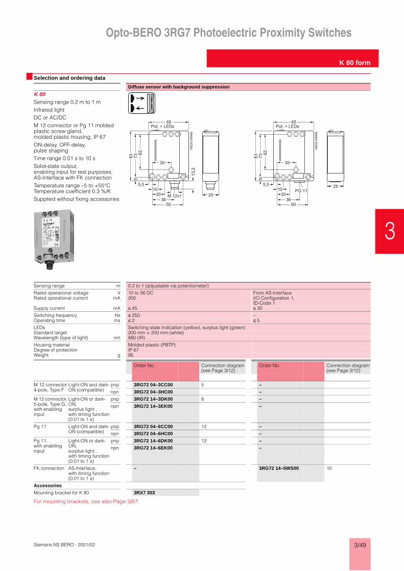
Opto-BERO 3RG7 Photoelectric Proximity Switches
K 80 form
Siemens NS BERO · 2001/02 3/49
3
Selection and ordering data
Diffuse sensor with background suppression
K 80Sensing range 0.2 m to 1 mInfrared lightDC or AC/DCM 12 connector or Pg 11 molded plastic screw gland, molded plastic housing, IP 67ON-delay, OFF-delay, pulse shapingTime range 0.01 s to 10 sSolid-state output, enabling input for test purposes, AS-Interface with FK connectionTemperature range –5 to +55°C Temperature coefficient 0.3 %/KSupplied without fixing accessories
NS
D0 0
084
6b
83
M 12x1
62
73
13,2
Pot. + LEDs
5
1020
3650
65
5,5
30
25
NS
D0 0
084
8b
83
PG 11
62
73
Pot. + LEDs
5
1020
3650
65
5,5
30
25
Sensing range m 0.2 to 1 (adjustable via potentiometer)
Rated operational voltage V 10 to 36 DC From AS-InterfaceRated operational current mA 200 I/O Configuration 1,
ID-Code 1Supply current mA ≤ 45 ≤ 30
Switching frequency Hz ≤ 250 –Operating time ms ≤ 2 ≤ 5LEDs Switching state indication (yellow), surplus light (green)Standard target 200 mm × 200 mm (white)Wavelength (type of light) nm 880 (IR)
Housing material Molded plastic (PBTP)Degree of protection IP 67Weight g 95
Order No. Connection diagram (see Page 3/12)
Order No. Connection diagram (see Page 3/12)
M 12 connector4-pole, Type F
Light-ON and dark-ON (compatible)
pnp 3RG72 04–3CC00 5 –
npn 3RG72 04–3HC00 –
M 12 connector, 5-pole, Type G, with enabling input
Light-ON or dark-ON, surplus light ,with timing function (0.01 to 1 s)
pnp 3RG72 14–3DK00 8 –
npn 3RG72 14–3EK00 –
Pg 11 Light-ON and dark-ON (compatible)
pnp 3RG72 04–6CC00 12 –
npn 3RG72 04–6HC00 –
Pg 11, with enabling input
Light-ON or dark-ON, surplus light ,with timing function (0.01 to 1 s)
pnp 3RG72 14–6DK00 12 –
npn 3RG72 14–6EK00 –
FK connection AS-Interface, with timing function (0.01 to 1 s)
– 3RG72 14–5WS00 10
Accessories
Mounting bracket for K 80 3RX7 303
For mounting brackets, see also Page 3/67.

Opto-BERO 3RG7 Photoelectric Proximity Switches
K 80 form
3/50 Siemens NS BERO · 2001/02
Selection and ordering data
Retroreflective sensor with polarization filter
K 80Range 6 m (autocollimation principle)Visible red lightDC or AC/DCM 12 connector or Pg 11 molded plastic screw gland, molded plastic housing, IP 67ON-delay, OFF-delay, pulse shapingTime range 0.01 s to 10 sSolid-state or relay output, enabling input for test purposes, AS-Interface with FK connectionTemperature range –5 to +55°C Temperature coefficient 0.3 %/KSupplied without fixing accessories and without reflector
NS
D0 0
084
6b
83
M 12x1
62
73
13,2
Pot. + LEDs
5
1020
3650
65
5,5
30
25
NS
D0 0
084
8b
83
PG 11
62
73
Pot. + LEDs
5
1020
3650
65
5,5
30
25
Range m 6 (adjustable via potentiometer)
Rated operational voltage V 10 to 36 DC 20 to 320 AC/DC, From AS-InterfaceRated operational current 200 mA 2 A (at 240 V AC) I/O Configuration 1,
ID-Code 1Supply current ≤ 30 mA ≤ 2 VA ≤ 30 mA
Switching frequency Hz ≤ 1000 ≤ 20 –Operating time ms ≤ 0.5 ≤ 20 ≤ 5LEDs Switching state indication (yellow), surplus light (green)Standard target Reflector type D 84, 3RX7 916Wavelength (type of light) nm 660 (red, polarized, visible)
Housing material Molded plastic (PBTP)Degree of protection IP 67Weight g 95
Order No. Connection diagram (see Page 3/12)
Order No. Connection diagram (see Page 3/12)
Preferred type Preferred type
M 12 connector4-pole, Type F
Light-ON and dark-ON (compatible)
pnp 3RG72 01–3CC00 5 –
npn 3RG72 01–3HC00 –
M 12 connector, 5-pole, Type G, with enabling input
Light-ON or dark-ON, surplus light , with timing function (0.01 to 1 s)
pnp 3RG72 11–3DK00 8 –
npn 3RG72 11–3EK00 –
Pg 11 Light-ON and dark-ON (compatible)
pnp 3RG72 01–6CC00 12 –
npn 3RG72 01–6HC00 –
Pg 11, with enabling input
Light-ON or dark-ON, surplus light , with timing function (0.01 to 1 s)
pnp 3RG72 11–6DK00 12 –
npn 3RG72 11–6EK00 –
Pg 11 Relay, light-ON and dark-ON, with timing function (0.1 to 10 s)
– 3RG72 11–6MC00 11
FK connection AS-Interface, with timing function (0.01 to 1 s)
– 3RG72 11–5WS00 10
Accessories
Mounting bracket for K 80 3RX7 303
For mounting brackets, see also Page 3/67.

Opto-BERO 3RG7 Photoelectric Proximity Switches
K 80 form
Siemens NS BERO · 2001/02 3/51
3
Selection and ordering data
Thru-beam sensor
K 80Range 50 mModulated infrared lightDC or AC/DCM 12 connector or Pg 11 molded plastic screw gland, molded plastic housing, IP 67ON-delay, OFF-delay, pulse shapingTime range 0.01 s to 10 sSolid-state or relay output, enabling input for test purposes, AS-Interface with FK connectionTemperature range –5 to +55°C Temperature coefficient 0.3 %/KSupplied without fixing accessories
NS
D0 0
084
6b
83
M 12x1
62
73
13,2
Pot. + LEDs
5
1020
3650
65
5,5
30
25
NS
D0 0
084
8b
83
PG 11
62
73
Pot. + LEDs
5
1020
3650
65
5,5
30
25
Range m 50 (adjustable via potentiometer)
Rated operational voltage V 10 to 36 DC 20 to 320 AC/DC, From AS-InterfaceRated operational current 200 mA 2 A I/O Configuration 1,
ID-Code 1Supply current ≤ 30 mA ≤ 2 VA ≤ 30 mA
Switching frequency Hz ≤ 1000 ≤ 20 –Operating time ms ≤ 0.5 ≤ 20 ≤ 5LEDs Switching state indication (yellow), surplus light (green)Standard target –Wavelength (type of light) nm 880 (IR)
Housing material Molded plastic (PBTP)Degree of protection IP 67Weight g 95
Order No. Connection diagram (see Page 3/12)
Order No. Connection diagram (see Page 3/12)
Receiver Preferred type Preferred type
M 12 connector4-pole, Type F
Light-ON and dark-ON (compatible)
pnp 3RG72 02–3CC00 5 –
npn 3RG72 02–3HC00 –
M 12 connector, 4-pole, Type F
Light-ON or dark-ON, surplus light , with timing function (0.01 to 1 s)
pnp 3RG72 12–3DK00 6 –
npn 3RG72 12–3EK00 –
Pg 11 Light-ON and dark-ON (compatible)
pnp 3RG72 02–6CC00 12 –
npn 3RG72 02–6HC00 –
Pg 11, with enabling input
Light-ON or dark-ON, surplus light , with timing function (0.01 to 1 s)
pnp 3RG72 12–6DK00 12 –
npn 3RG72 12–6EK00 –
Pg 11 Relay, light-ON and dark-ON, with timing function (0.1 to 10 s)
– 3RG72 12–6MC00 11
FK connection AS-Interface, with timing function (0.01 to 1 s)
– 3RG72 12–5WS00 10
Emitter
M 12 connector, 4-pole, Type F 3RG72 02–3BG00 7 –
Pg 11 3RG72 02–6BG00 12 3RG72 02–6FG00 12
FK connection for AS-Interface – 3RG72 02–5WG00 10
Accessories
Mounting bracket for K 80 3RX7 303
For mounting brackets, see also Page 3/67.

Opto-BERO 3RG7 Photoelectric Proximity Switches
KL 40 form
3/52 Siemens NS BERO · 2001/02
Selection and ordering data
BERO for plastic fiber-optic conductor
KL 40Snap-on fitting (standard mounting rail)10 to 30 V DCCable or M 8 connectorMolded plastic housing, IP 65Programmable via teach-inSolid-state output npn or pnpTemperature range –10 to +55 °CSupplied without fixing accessories
64
44.5
25.75 24.65
3.6
6.3
12
17
16
12
NS
D00849
Programming
LED GN/RD
LED YE
Sensing range mm Max. 280
Rated operational voltage (DC) V 10 to 30Rated operational current mA 100Supply current mA < 55
Switching frequency Hz 1500Operating time µs 333
LEDs Switching state (yellow), Set (red/green)Standard target –Wavelength (type of light) nm 660 (red)
Housing material Molded plastic (ABS)Degree of protection IP 65Weight g 100
Order No. Connection diagram (see Page 3/13)
Preferred type
2 m cable, PVC, 6 × 0.088 mm2
pnp, light-ON or dark-ON
3RG74 13–1CH00 34
npn, light-ON or dark-ON
3RG74 13–1HH00 34
M 8 connector, 4-pole, Type B
pnp, light-ON or dark-ON
3RG74 13–7CH00 23
npn, light-ON or dark-ON
3RG74 13–7HH00 23
Accessories
Mounting bracket for KL 40 3RX7 313
For mounting brackets, see also Page 3/66.For plastic fiber-optic conductors, see Pages 3/60 and 3/61.

Opto-BERO 3RG7 Photoelectric Proximity Switches
CL 40 form
Siemens NS BERO · 2001/02 3/53
3
Selection and ordering data
Color sensor
CL 40Sensing range 3 to 15 mm10 to 30 V DCCable or M 8 connectorMolded plastic housing, IP 65Programmable via teach-inVersion with cable: Also with remote teach-in and alarm outputSolid-state output npn/pnpTiming functionTemperature range –10 to +55 °CSupplied without fixing accessoriesSupplied with plastic fiber-optic conductor 3RX7 011
98
88
12
1224.6525.75
3.6
6.3
64
NS
D00850
44.5
Programming
LED RD/GN
LED YE
LED GN
Sensing range mm 3 to 15
Rated operational voltage (DC) V 10 to 30Rated operational current mA 100Supply current mA < 60
Switching frequency Hz 550Operating time µs 100
LEDs Switching state (yellow), programming (red/green), timer (green)Standard target –Wavelength (type of light) nm 3 LEDs: 660 (red), 525 (green), 470 (blue)
Housing material Molded plastic (ABS)Degree of protection IP 65Weight g 40
Order No. Connection diagram (see Page 3/13)
Preferred type
2 m cable, PVC, 6 × 0.088 mm2
pnp 3RG75 50–1CA00 35
npn 3RG75 50–1HA00 35
M 8 connector, 4-pole, Type B
pnp 3RG75 50–7CA00 25
npn 3RG75 50–7HA00 25
Accessories
Plastic fiber-optic conductor, 1 m long, for color sensor CL 40
3RX7 011
Mounting bracket for CL 40 3RX7 313
For mounting brackets, see also Page 3/66.

Opto-BERO 3RG7 Photoelectric Proximity Switches
C 80 form
3/54 Siemens NS BERO · 2001/02
Selection and ordering data
Color mark sensor
C 80Sensing range 9 or 18 mm10 to 30 V DCCable or M 12 connectorMetal housing, IP 67Programmable via teach-inON-delay, switchableSolid-state output pnp, analog output 0 to 5.5 VHorizontal or vertical light spotTemperature range –10 to +55 °CSupplied without fixing accessories
36.6 28 M 5
M 1
2x1
39
.8
24
42
.258
9
4.3
MARK BKGR
READY OUT
NSD00851
7.5
18
∅25
31
5.982.8
M 5 15
21
14.1 27.5 28
∅25
33.7
M 1220.9
Sensing range mm 9 18
Rated operational voltage (DC) V 10 to 30Rated operational current mA 200Supply current mA < 80
Analog output (R i = 22 kΩ) V 0 ... 5.5
Switching frequency kHz 10Operating time µs 50
LEDs Switching state (yellow), Ready (green)Standard target –Wavelength (type of light) nm 660 (red) or 565 (green); automatic selection
Housing material Aluminum die-castDegree of protection IP 67Weight g 560
Order No. Connection diagram (see Page 3/13)
Order No. Connection diagram (see Page 3/13)
Preferred type Preferred type
3 m cable, PVC, 6 × 0.15 mm² shielded
pnp, light-ON or dark-ON, vertical light spot
3RG75 60–1CH55 36 3RG75 60–1CH54 36
M 12 connector4-pole, Type F
pnp, light-ON or dark-ON, vertical light spot
3RG75 60–3CH55 26 3RG75 60–3CH54 26
pnp, light-ON or dark-ON, horizontal light spot
3RG75 60–3CH53 26 3RG75 60–3CH56 26

Opto-BERO 3RG7 Photoelectric Proximity Switches
G 20 form
Siemens NS BERO · 2001/02 3/55
3
Selection and ordering data
Fork/slot, visible red/green Fork/slot, infrared
G 20Fork/slot width 2 mm10 to 30 V DCM 8 connectorMetal housing, IP 65Solid-state output, pnp and npnTeach-inTemperature range 0 to +55 °CSupplied without fixing accessories
16
12
904.25
7.5
18
4
18426
6
50
99
26
20
8
M8
97.5
20
7.5
2
NSD00852M4
Fork/slot width mm 2
Rated operational voltage (DC) V 10 to 30 Rated operational current mA 100Supply current mA < 55
Switching frequency kHz 6Operating time µs 80
LEDs Switching state (yellow)Standard target –Wavelength (type of light) nm Green/red IR
Housing material Aluminum die-castDegree of protection IP 65Weight g 115 g
Order No. Connection diagram (see Page 3/13)
Order No. Connection diagram (see Page 3/13)
Preferred type Preferred type
M 8 connector, 4-pole, Type B
pnp/npn, light-ON or dark-ON
3RG75 02–7RH57 24 3RG75 02–7RH58 24

Opto-BERO 3RG7 Photoelectric Proximity Switches
L 18 form (Laser)
3/56 Siemens NS BERO · 2001/02
Selection and ordering data
Laser thru-beam sensor
L 18Range 50 mVisible laser light, Laser Protection Class 210 to 30 V DCCable or M 12 connectorIP 65Solid-state outputTemperature range –10 to +60°C Temperature coefficient 0.1 %/KSupplied with focussing and adjustment tool; without fixing accessories
Straight optical system
Angular optical system
M 18x1
SW
24
4N
SD
0 0
0853
48
75
LED
Pot.
M 18x1
SW
24
4
NSD00854
37
64
5
4
27,7
SW
24
NSD00855
48
75
M 1
8x1
20
4N
SD
0 0
0856
48
75
LED
Pot.
SW
24
M 1
8x1 4
28,7
NS
D00857
75
5
SW
24
M 1
8x1
M 18x1
SW
24
NS
D0 0
0858
48
75
LED
Pot.
M 12x1
4
M 18x1
SW
24
4
NSD00859
37
64
M 12x1
5
4
27,7
NSD00860
48
75
M 12x1
SW
24
M 1
8x1
20
4N
SD
0 0
0861
48
75
LEDPot.
M 12x1
SW
24
M 1
8x1 4
28,7
NS
D00862
75
5
M 12x1
SW
24
M 1
8x1
Range m 50 (adjustable via potentiometer)
Rated operational voltage (DC) V 10 to 30Rated operational current mA 200No-load supply current I0 (typ.) mA Emitter: ≤ 10, receiver: ≤ 15
Switching frequency Hz 6000Operating time µs ≤ 83
LEDs Operating voltage (green), switching state indication (yellow), surplus light (red)Standard target –Wavelength (type of light) nm 660 (red laser light, visible)
Housing material Brass, nickel-platedDegree of protection IP 65Weight (cable/connector) g 75 / 175
Order No. Connection diagram (see Page 3/12)
Order No. Connection diagram (see Page 3/12)
Receiver
3 m cable, PUR, 4 × 0.25 mm²
pnp, light-ON, dark-ON (compatible)
3RG71 35–0CC00 5 3RG71 75–0CC00 5
pnp, light-ON and surplus light function
3RG71 35–0CD00 6 3RG71 75–0CD00 6
M 12 connector4-pole, Type F
pnp, light-ON, dark-ON (compatible)
3RG71 35–3CC00 5 3RG71 75–3CC00 5
pnp, light-ON and surplus light function
3RG71 35–3CD00 6 3RG71 75–3CD00 6
Emitter
3 m cable, PUR, 4 × 0.25 mm² 3RG71 35–0BE00 9 3RG71 75–0BE00 9
M 12 connector, 4-pole, Type F 3RG71 35–3BE00 9 3RG71 75–3BE00 9
Accessories
Mounting bracket for L 18 3RX7 300
For mounting brackets, see also Page 3/68.

Opto-BERO 3RG7 Photoelectric Proximity Switches
L 50 form (Laser)
Siemens NS BERO · 2001/02 3/57
3
Selection and ordering data
Laser diffuse sensor with background suppression Laser diffuse sensor
L 50Sensing range 30 to 150 mm (diffuse sensor with background suppr.)Range 12 m (retroreflective sensor)
Visible laser light, Laser Protection Class 2Cable or M 12 connectorIP 67Solid-state outputTemperature range –20 to +45°C Temperature coefficient 0.1 %/KSupplied without fixing accessories and without reflector
17
50
NS
D0 0
0863
50
4,3
Pot. + LEDs4
4044
44
16
46
17
50
NS
D0 0
0863
50
4,3
Pot. + LEDs4
4044
44
16
46
17
50
NS
D0 0
0864
50
4,3
M 12x1M 12x1
44
16
46
4440
4
27
,5
Pot. + LEDs 17
50
NS
D0 0
0864
50
4,3
M 12x1M 12x1
44
16
46
4440
4
27
,5
Pot. + LEDs
Sensing range/Range 30 to 150 mm (adjustable via potentiometer) 12 m (adjustable via potentiometer)
Rated operational voltage (DC) V 10 to 30 (max. 10 % residual ripple) 10 to 30 (max. 10 % residual ripple)Rated operational current mA 200 200No-load supply current I0 (typ.) mA ≤ 50 ≤ 50
Switching frequency Hz 2500 2500Operating time µs ≤ 200 ≤ 200
LEDs Operating voltage (green), switching state (yellow), surplus light (red)
Operating voltage (green), switching state (yellow), surplus light (red)
Standard target 100 mm × 100 mm (white) Reflector type RL 50, 3RX7 307Wavelength (type of light) nm 670 (red laser light) 670 (red laser light)
Housing material Molded plastic (ABS) Molded plastic (ABS)Degree of protection IP 67 IP 67Weight (cable/connector) g 140 / 40 145 / 45
Order No. Connection diagram (see Page 3/12)
Order No. Connection diagram (see Page 3/12)
Preferred type
2 m cable, PUR, 4 × 0.25 mm²
pnp, light-ON and dark-ON
3RG70 56–0CC00 5 3RG70 57–0CC00 5
pnp, light-ON and surplus light function
3RG70 56–0CD00 6 3RG70 57–0CD00 6
npn, light-ON and dark-ON
3RG70 56–0HC00 5 3RG70 57–0HC00 5
npn, light-ON and surplus light function
3RG70 56–0HD00 6 3RG70 57–0HD00 6
M 12 connector4-pole, Type F
pnp, light-ON and dark-ON
3RG70 56–3CC00 5 3RG70 57–3CC00 5
pnp, light-ON and surplus light function
3RG70 56–3CD00 6 3RG70 57–3CD00 6
npn, light-ON and dark-ON
3RG70 56–3HC00 5 3RG70 57–3HC00 5
npn, light-ON and surplus light function
3RG70 56–3HD00 6 3RG70 57–3HD00 6
Accessories
Mounting bracket for L 50 3RX7 302
For mounting brackets, see also Page 3/67.

Opto-BERO 3RG7 Photoelectric Proximity Switches
L 50 form (Laser)
3/58 Siemens NS BERO · 2001/02
Selection and ordering data
Characteristic
Laser diffuse sensor with analog output
L 50Sensing range 45 to 85 mmResolution 80 µm/20 µmVisible laser light, Laser Protection Class 2 (acc. to IEC 825/VDE 0837)CableIP 67Voltage output 0 to 10 VTemperature range 0 to +45 °C, temperature drift 18 µm/KSupplied without fixing accessories
17
50
NS
D0 0
0863
50
4,3
Pot. + LEDs4
4044
44
16
46
Sensing range mm 45 to 85 (adjustable via potentiometer)
Resolution µm 80 20Linearity < 1 % of measuring range (40 mm)
Rated operational voltage (DC) V 18 to 28Analog output V 0 to 10 / max. 3 mANo-load supply current I0 (typ.) mA ≤ 35
Switching frequency Hz 500 50Operating time ms 1 10
LEDs Operating voltage (green), surplus light (red)Spot size when sensor is 65 mm from target
mm < 0.8
Housing material Molded plastic (ABS)Degree of protection IP 67Weight g 280
Order No. Connection diagram (see Page 3/13)
Order No. Connection diagram (see Page 3/13)
6 m cable, PVC, 4 × 0.34 mm² shielded
Analog output 0 to 10 V, rising
3RG70 56–1CM00 37 3RG70 56–1CM03 37
M 12 connector4-pole, Type F
Analog output 0 to 10 V, rising
3RG70 56–3CM00 37 3RG70 56–3CM03 37
Accessories
Cable plug, shielded, 4 × 0.34 mm² 3RX1 680
Right angle cable plug, shielded, 4 × 0.34 mm²
3RX1 681
Mounting bracket for L 50 3RX7 302
For mounting brackets, see also Page 3/67.
NS
D00
865
85 mm45 mm
10 V
0 V
Measuring range

Opto-BERO 3RG7 Photoelectric Proximity Switches
Light array
Siemens NS BERO · 2001/02 3/59
3
Selection and ordering data
Retroreflective sensor with polarization filter
LGRange 1.4 mVisible red light, 7 light beamsAutocollimation principle12 to 36 V DCM 8 connectorIP 54Solid-state outputTemperature range –10 to +50°C Temperature coefficient 0.1 %/KSupplied with fixing accessoriesSupplied without reflector
746
16
23
3060
M 4
2045
12
60
6x7
=42
9
NS
D00866
Direction of travel
A
LED YELED RE
Sensing range m 1.4
Rated operational voltage (DC) V 12 to 36Rated operational current mA Max. 200No-load supply current I0 (typ.) mA < 30
Switching frequency Hz 50Operating time ms 10
LEDs Switching state indication (yellow), fouling indic. (red)Standard target Reflector type R 45, 3RX7 924Wavelength (type of light) nm 660 (red, polarized, visible)
Housing material Molded plastic (PBTP, Crastin)Degree of protection IP 54Weight g 120
Order No. Connection diagram (see Page 3/12)
Preferred type
M 8 connector, 4-pole, Type B
pnp, dark-ON and surplus light function
3RG70 71–7CD27 6
The switching output switches as soon as one of the 7 beams is interrupted.
Accessories
Reflector type R 45 3RX7 924

Opto-BERO 3RG7 Photoelectric Proximity Switches
3RX7 plastic fiber-optic conductors
3/60 Siemens NS BERO · 2001/02
OverviewThe plastic fiber-optic conduc-tors are used in conjunction with the Opto-BEROs of types K 30, K 31, K 35 and KL 40.The sensing range of the plas-tic fiber-optic conductors de-pends on the type of Opto-BERO used.
The main advantages are:• Extremely small dimensions• Small bending radius• For cutting to length• Visible light• Wide range of types• Attractively priced
Typical beam diagram (fiber type 3RX7 003)
Technical data
Selection and ordering data
NSD00913a
40
30
20
10
50
01020 10 20 (mm)a
TW
TW (mm)
a
TW = Sensing range
Temperature range –40 to +75 °C
Degree of protection• Sensor head IP 67• Sensor IP 65
Standard length 2 m ± 0.1 m
Bending radius Min. 25 mm
Tensile strength Max. 30 N
Attenuation Max. 0.4 dB/m at 660 nm
Sleeve material Polyethylene
Angle of incidence Max. ± 56°
Solvent resistance Not resistant
Design Order No. Weight
kg
Plastic fiber-optic conductors for diffuse sensorsSensing range:
Series K 31Series K 30Series K 35Series KL 40
20 mm40 mm20 mm35 mm
3RX7 001 0.01
2 individual fibers Ø 1 mm, can be cut
Adapter sleeves for Ø 2.2 mm contained in the scope of supply.
Sensing range:
Series K 31Series K 30Series K 35Series KL 40
60 mm120 mm50 mm
110 mm
3RX7 002 0.01
2 individual fibers Ø 2.2 mm, can be cut
Sensing range:
Series K 31Series K 30Series K 35Series KL 40
20 mm40 mm20 mm35 mm
3RX7 004 0.01
2 individual fibers Ø 1 mm, can be cut
Adapter sleeves for Ø 2.2 mm contained in the scope of supply.
Sensing range:
Series K 31Series K 30Series K 35Series KL 40
60 mm120 mm16 mm
100 mm
3RX7 005 0.01
2 individual fibers Ø 2.2 mm, can be cut
712
2000 +- 100
M 3 (P=0,5)NSD00914
∅ 1
1,815
2000 +- 100
M 6 (P=0,75)
2,2
NSD00915
712
2000 +- 100
M 3 (P=0,5)NSD00917
90+- 2
1,2 ∅ 1
1,815
2000 +- 100
M 6 (P=0,75)NSD00918
90
∅ 2,2 ∅ 2,5

Opto-BERO 3RG7 Photoelectric Proximity Switches
3RX7 plastic fiber-optic conductors
Siemens NS BERO · 2001/02 3/61
3
Selection and ordering data
Design Order No. Weight, approx.kg
Plastic fiber-optic conductors for thru-beam sensorsRange: Series K 31
Series K 30Series K 35Series KL 40
60 mm120 mm32 mm90 mm
3RX7 006 0.01
2 individual fibers Ø 2.2 mm, can be cut
(fine internal fiber)
Range: Series K 31Series K 30Series K 35Series KL 40
200 mm400 mm50 mm
280 mm
3RX7 007 0.01
2 individual fibers Ø 2.2 mm, can be cut
Range: Series K 31Series K 30Series K 35Series KL 40
60 mm120 mm14 mm60 mm
3RX7 008 0.01
2 individual fibers Ø 2.2 mm, can be cut
(fine internal fiber)
Range: Series K 31Series K 30Series K 35Series KL 40
200 mm400 mm75 mm
280 mm
3RX7 010 0.01
2 individual fibers Ø 2.2 mm, can be cut
Front lensesFront lenses (1 pair)
for use with 3RX7 007 fiber type
3RX7 901 0.02
Range: Series K 31Series K 30Series K 35Series KL 40
1500 mm3000 mm250 mm
2000 mm
Front lenses 90° (1 pair)
for use with 3RX7 007 fiber type
3RX7 902 0.02
Range: Series K 31Series K 30Series K 35Series KL 40
250 mm500 mm
20 mm350 mm
712
2000 +- 100
M 3 (P=0,5)NSD00919
∅ 2,2 ∅ 3
3112000 +- 100
M 4 (P=0,7)
NSD00920
M 2,6 (P=0,45)
∅ 2,2
712
2000 +- 100
M 3 (P=0.5)NSD00921
90+- 2
∅ 2.2 ∅ 0.9
90112000 +- 100
M 4 (P=0,7)
NSD00922
+- 2
∅ 2,2
∅ 1,2
NSD00923
8,75,5M 2,6 (P=0,45)
∅ 4
∅ 4
,5
NSD00924
9,75,8
M 2,6 (P=0,45)
∅ 4
,5

Opto-BERO 3RG7 Photoelectric Proximity Switches
3RX7 glass fiber-optic conductors
3/62 Siemens NS BERO · 2001/02
Overview
The glass fiber-optic conduc-tors are used in conjunction with the Opto-BEROs of type K 40.The main advantages are:• Small dimensions• Wide range of types• Large selection of fibers and
sensor heads• Detection of extremely small
parts
Depending on the type, glass fiber-optic conductors comprise 200 to 5000 individual fibers with a diameter of 30 to 50 mm. The bundle of fibers is surrounded by a sheath that can be selected according to the application:• Wound sheath of chrome-
plated brass• Silicon sheath with stainless
steel braiding for strain-relief for use in corrosive media and under mechanical stress.
The sensor heads are available with light outlet at the front or side. The range includes glass optical fibers for operation in retroreflective mode (with separate bundles of fibers for emitter and receiver) and for operation as diffuse sensors (the bundles for emitter and receiver are located in a common sleeve).
Typical beam diagram
Technical data
Selection and ordering data
NS
D00
925
Temperature range• Silicon sheath –25 °C to +150 °C • Wound sheath –25 °C to +250 °C
Sensor head degree of protection IP 54 (optionally IP 68)
Optical fiber degree of protection• With wound sheath of chrome-
plated brassIP 50
• With silicon sheath sleeve IP 65
Standard lengths 0.25 m; 0.5 m; 1.0 m
Attenuation at 880 nm Max. 0.4 dB/m
Angle of incidence Max. ± 32°
Solvent resistance Not resistant
Design Order No. Weight, approx.
kg
Glass fiber-optic conductors for axial diffuse sensorsSensing range 5 mm
With flexible light outlet sleeve (minimum radius 4 mm) for detecting the smallest objects
Sheath: Silicon sheath Ø 4.7 mmMin. bending radius 20 mmMax. tensile strength 10 N
Length 250 mm
500 mm
1000 mm
3RX7 101–0CF
3RX7 101–0FA
3RX7 101–1AA
0.01
0.02
0.04
For special lengths, see Page 4/65.
Sensing range 15 mm
With flexible light outlet sleeve (minimum radius 5 mm) for practically inaccessible locations
Sheath: Silicon sheath Ø 4.7 mmMin. bending radius 20 mmMax. tensile strength 10 N
Length 250 mm
500 mm
1000 mm
3RX7 104–0CF
3RX7 104–0FA
3RX7 104–1AA
0.01
0.02
0.04
For special lengths, see Page 4/65.
Sensing range 15 mm
For detecting extremely small objects
Sheath: Wound sheath of chrome-plated brass Ø 4.7 mmMin. bending radius 23 mmMax. tensile strength 10 N
Length 250 mm
500 mm
1000 mm
3RX7 107–0CF
3RX7 107–0FA
3RX7 107–1AA
0.01
0.02
0.04
For special lengths, see Page 4/65.
6 15
12
75
55056
1 0,7
NSD00926
6 15
12
100
58056
1,5 1
NSD00927
6 15 12 25
6
1
NSD00928

Opto-BERO 3RG7 Photoelectric Proximity Switches
3RX7 glass fiber-optic conductors
Siemens NS BERO · 2001/02 3/63
3
Selection and ordering data
Design Order No. Weight, approx.
kg
Glass fiber-optic conductors for axial diffuse sensors (continued)Sensing range 50 mm
Universal sensor of medium range
Sheath: Wound sheath of chrome-plated brass Ø 6.7 mmMin. bending radius 25 mmMax. tensile strength 300 N
Length 250 mm
500 mm
1000 mm
3RX7 111–0CF3RX7 111–0FA3RX7 111–1AA
0.010.020.04
For special lengths, see Page 4/65.
Sensing range 150 mm
Sheath: Wound sheath of chrome-plated brass Ø 6.7 mmMin. bending radius 25 mmMax. tensile strength 300 N
Length 250 mm
500 mm
1000 mm
3RX7 114–0CF3RX7 114–0FA3RX7 114–1AA
0.010.020.04
For special lengths, see Page 4/65.
Axial headsSensing range 100 mm
For reducing the sensing range to 100 mm
Housing material: Polyamide
3RX7 903 0.02
Sensing range 150 mm
For reducing the sensing range to 150 mm
Housing material: Polyamide
3RX7 904 0.02
Glass fiber-optic conductors for radial diffuse sensorsSensing range 15 mm
For detecting the smallest objects
Limb length 14 mmSheath: Wound sheath of chrome-plated brass Ø 4.7 mmMin. bending radius 23 mmMax. tensile strength 10 N
Length 250 mm
500 mm
1000 mm
3RX7 201–0CF
3RX7 201–0FA
3RX7 201–1AA
0.01
0.02
0.04
For special lengths, see Page 4/65.
Sensing range 30 mm
Universal design
Limb length 14 mmSheath: Wound sheath of chrome-plated brass Ø 6.7 mmMin. bending radius 25 mmMax. tensile strength 300 N
Length 250 mm
500 mm
1000 mm
3RX7 204–0CF
3RX7 204–0FA
3RX7 204–1AA
0.01
0.02
0.04
For special lengths, see Page 4/65.
Sensing range 15 mm
Limb length 14 mm
Sheath: Wound sheath of chrome-plated brass Ø 6.7 mmMin. bending radius 25 mmMax. tensile strength 300 N
Length 250 mm
500 mm
1000 mm
3RX7 207–0CF
3RX7 207–0FA
3RX7 207–1AA
0.01
0.02
0.04
For special lengths, see Page 4/65.
6 15 12 25
8
5
NSD00929 10
6 15 12 25
8
6
NSD00930 10
3
12
24
3
NSD00931
156 15,3
3
12
24
3
NSD00931
156 15,3
6 15 12 206
NSD00932
1,5
14
1,25
6 15 12 208
NSD00933
5
14
3,5
6 15 12 208
NSD00934
6
14
4

Opto-BERO 3RG7 Photoelectric Proximity Switches
3RX7 glass fiber-optic conductors
3/64 Siemens NS BERO · 2001/02
Selection and ordering data
Design Order No. Weight, approx.
kg
Radial headsSensing range 100 mm
For reducing the sensing range to 100 mm
Housing material: Polyamide
3RX7 907 0.02
Sensing range 150 mm
For reducing the sensing range to 150 mm
Housing material: Polyamide
3RX7 908 0.02
Glass fiber-optic conductors for axial thru-beam sensorsRange 50 mm
With flexible light outlet sleeve (minimum radius 4 mm) for detecting the smallest objects
Sheath: Silicon sheath Ø 4.7 mmMin. bending radius 20 mmMax. tensile strength 10 N
Length 250 mm
500 mm
1000 mm
3RX7 117–0CF
3RX7 117–0FA
3RX7 117–1AA
0.02
0.04
0.08
For special lengths, see Page 4/65.
Range 200 mm
With flexible light outlet sleeve (minimum radius 5 mm) for practically inaccessible locations
Sheath: Silicon sheath Ø 4.7 mmMin. bending radius 20 mmMax. tensile strength 10 N
Length 250 mm
500 mm
1000 mm
3RX7 121–0CF
3RX7 121–0FA
3RX7 121–1AA
0.02
0.04
0.08
For special lengths, see Page 4/65.
Range 200 mm
For detecting the smallest objects
Sheath: Wound sheath of chrome-plated brass Ø 4.7 mmMin. bending radius 23 mmMax. tensile strength 10 N
Length 250 mm
500 mm
1000 mm
3RX7 124–0CF
3RX7 124–0FA
3RX7 124–1AA
0.025
0.05
0.1
For special lengths, see Page 4/65.
Range 800 mm
Universal design
Sheath: Wound sheath of chrome-plated brass Ø 4.7 mmMin. bending radius 23 mmMax. tensile strength 300 N
Length 250 mm
500 mm
1000 mm
3RX7 127–0CF
3RX7 127–0FA
3RX7 127–1AA
0.025
0.05
0.1
For special length, see Page 4/65.
Range 1500 mm
Sheath: Wound sheath of chrome-plated brass Ø 5.1 mmMin. bending radius 24 mmMax. tensile strength 300 N
Length 250 mm
500 mm
1000 mm
3RX7 131–0CF
3RX7 131–0FA
3RX7 131–1AA
0.025
0.05
0.1
For special lengths, see Page 4/65.
4
12
NSD00935
6 15,3
13
5
2115
∅
4
12
NSD00935
6 15,3
13
5
2115
∅
6 15
12
75
55056
1 0,7
NSD00936
6 15
12
100
58056
1,5 1
NSD00937
6 15 12 25
6
1
NSD00938
6 15 12 25
8
6
NSD00939 10
6 15 12 25
8
6
NSD00939 10

Opto-BERO 3RG7 Photoelectric Proximity Switches
3RX7 glass fiber-optic conductors
Siemens NS BERO · 2001/02 3/65
3
Selection and ordering data
Special designs
Special lengths for glass fiber-optic conductorsThe design is indicated in the first seven positions of the Or-der No. in accordance with Pages 4/62 to 4/65.
Positions 8 to 10 ("–0AZ") indi-cate special lengths.The required length must be specified in the order as fol-lows: Order No. and additional-ly the length in cm.
Ordering exampleThe glass fiber-optic conductor 3RX7 127 is ordered with a length of 75 cm. The order is specified as follows:3RX 127–0AZ Length: 75 cm
Design Order No. Weight, approx.
kg
Glass fiber-optic conductors for radial thru-beam sensorsRange 200 mm
For detecting extremely small objects
Sheath: Wound sheath of chrome-plated brass Ø 4.7 mmMin. bending radius 23 mmMax. tensile strength 10 N
Length 250 mm
500 mm
1000 mm
3RX7 211–0CF
3RX7 211–0FA
3RX7 211–1AA
0.025
0.05
0.1
For special lengths, see below.
Range 800 mm
Universal design
Sheath: Wound sheath of chrome-plated brass Ø 4.7 mmMin. bending radius 23 mmMax. tensile strength 300 N
Length 250 mm
500 mm
1000 mm
3RX7 214–0CF
3RX7 214–0FA
3RX7 214–1AA
0.025
0.05
0.1
For special lengths, see below.
Range 1500 mm
Sheath: Wound sheath of chrome-plated brass Ø 5.1 mmMin. bending radius 24 mmMax. tensile strength 300 N
Length 250 mm
500 mm
1000 mm
3RX7 217–0CF
3RX7 217–0FA
3RX7 217–1AA
0.025
0.05
0.1
For special lengths, see below.
6 15 12 206
NSD00940
1,5
14
1,25
6 15 12 208
NSD00941
5
14
3,5
6 15 12 208
NSD00942
6
14
4
Order No. Order No. Order No.
3RX7 101–0AZ 3RX7 204–0AZ 3RX7 131–0AZ
3RX7 104–0AZ 3RX7 207–0AZ 3RX7 211–0AZ
3RX7 107–0AZ 3RX7 117–0AZ 3RX7 214–0AZ
3RX7 111–0AZ 3RX7 121–0AZ 3RX7 217–0AZ
3RX7 114–0AZ 3RX7 124–0AZ
3RX7 201–0AZ 3RX7 127–0AZ

Opto-BERO 3RG7 Photoelectric Proximity Switches
3RX7 accessories
3/66 Siemens NS BERO · 2001/02
Selection and ordering data
Design Order No. Weight, approx.kg
Mounting bracketsMounting bracket for Opto-BEROs of Series K 20
3RX7 308 0.013
Mounting bracket for Opto-BEROs of Series K 30, K 31
Material: Galvanized steel
3RX7 910 0.02
Mounting bracket for 35 mm mounting rail for Opto-BEROs of Series K 30, K 31
Material: Galvanized steel
3RX7 304 0.032
Mounting bracket for Opto-BEROs of Series K 35, KL 40 and CL 40
3RX7 313 0.017
Mounting bracket for Opto-BEROs of Series K 40 (included in scope of supply)
Material: Galvanized steel
3RX7 911 0.035
3,3
30
7,5
NSD00943
20 1,2
146
3,3
5
18,753,3
∅
21 4,5
∅4,2
10°10°
214,
5
16,5
42
8°8°
4,5 2130
33
1,5
7,5
NS
D0
09
44
a
∅4,2
∅4,2∅4,2
2141
4,5
21
4,5
30
49
37,5
15 NSD00945a
NSD00946
1 13,8
4
3413,8
4
4,2x12
11
4,2x12
1
19
19
1
31 4,5
10°10°
314,
5
16,5
52
8°8°
4,5 2130
45
1,5
7,5
NS
D0
09
47
a
∅4,2
∅4,2
∅4,2
∅4,2

Opto-BERO 3RG7 Photoelectric Proximity Switches
3RX7 accessories
Siemens NS BERO · 2001/02 3/67
3
Selection and ordering data
Design Order No. Weight, approx.kg
Mounting bracketsMounting bracket for Opto-BEROs of Series K 50
3RX7 310 0.061
Mounting bracket for Opto-BEROs of Series K 65
3RX7 311 0.08
Mounting bracket for Opto-BEROs of Series K 80
Material: Galvanized steel
3RX7 303 0.245
Mounting bracket for Laser BEROs of Series L 50
Material: Galvanized steel
3RX7 302
NSD00948
20
40
9
2
10°
40 560
15
58
9
20°
40∅ 4,5
∅ 4,5
∅ 5,5
∅ 6,510
°
NSD00949
16°
22
530
9
2
46,4
12
30°
15°
36
55
5,5
36 575
2
R36
4
R36
∅ 4,2
∅ 6,4
R62
R73
16°
8°
5137
63
10R14
R25
R25
34°63°
NSD00950
26,5
3013
31,5
∅5,3
19
48
24°
423
32
49
2
NS
D0
09
51
∅4,3 7,5
4,3
10,5

Opto-BERO 3RG7 Photoelectric Proximity Switches
3RX7 accessories
3/68 Siemens NS BERO · 2001/02
Selection and ordering data
Design Order No. Weight, approx.kg
Mounting bracketsMounting bracket for Opto-BEROs with M 18 housing
(alignable, specially designed for laser BEROs of Series L 18)
Material: Galvanized steel
3RX7 300
Universal mounting bracket for Opto-BEROs with M 18 housing
Material: Galvanized steel
3RX7 301
Metal supports and cutting tool for fiber-optic conductorsMetal support for fiber-optic conductors
• Ø 3.5 mm 3RX7 940 0.03
• Ø 4.5 mm 3RX7 941 0.03
• Ø 6 mm 3RX7 942 0.03
• Ø 7 mm 3RX7 943 0.04
• Ø 8 mm 3RX7 944 0.04
• Ø 10 mm 3RX7 945 0.04
Cutting tool for plastic fiber-optic conductors 3RX7 918 0.02
28
13
30
42
4,2x6,2
50
50 M 18
NSD00952
20
18,5 40
33 1
2
6
40
32
NS
D0
09
53
M 3
A
12168
NS
D00
954
4
B ∅3,
2∅
6
A
B3,5
204,5
206
207
25
825
1025
51NS
D00
95
5

Opto-BERO 3RG7 Photoelectric Proximity Switches
3RX7 accessories
Siemens NS BERO · 2001/02 3/69
3
Selection and ordering data
Design Order No. Weight, approx.kg
ReflectorsD 22
25 mm diameter
Range typ. approx. 40% of that for Type D 84 (3RX7 916)
3RX7 914 0.005
D 40
46 mm diameter
Range typ. approx. 60% of that for Type D 84 (3RX7 916)
3RX7 915 0.01
D 84
85 mm diameter
3RX7 916 0.02
S 48
Range typ. approx. 50% of that for Type D 84 (3RX7 916)
3RX7 922 0.01
R 70
Range typ. approx. 30% of that for Type D 84 (3RX7 916)
3RX7 920 0.005
R 45
Range typ. approx. 60% of that for Type D 84 (3RX7 916)
3RX7 924 0.01
R 60
Reflector 40 mm × 60 mm
Range typ. approx. 40 to 50 % of that for Type D 84 (3RX7 916)
3RX7 305 0.01
R 84
Reflector 84 mm × 84 mm, high reflection factor for wide ranges
3RX7 306 0.02
RL 50
Laser reflector 50 mm × 50 mm, special reflector for laser retroreflective sensors
3RX7 307 0.01
Reflecting foil 100 mm × 100 mm 3RX7 917 0.005
25 2,25
NS
D0
095
6
46 6NS
D0
095
7
85 10NS
D0
095
8
8,5
4,8
48 74
NS
D0
09
59
55
86
8,5
ø4,
5
5
71 82
7,5
ø4,
5
4
NS
D0
096
0
22,5
ø8
45 51 61 71
365860
8
ø4,
3
4
NS
D0
096
1
52 60
34
NS
D0
096
2
40,5
ø3,
5
77 84,5
77
NS
D0
096
3
84,5
ø3,
5
51 61
10
NS
D0
096
4
51,5
4,3

BERO 3RG4 Inductive Proximity Switches
4/2 Siemens NS BERO · 2001/02
Mini (D 3 to D 6.5, M 5,
Shorty (M 8 to M 30)
Cylindrical type (M 8 to M 30)
3RG4 Page 3RG4 Page 3RG4 Page
Selection and ordering data 4/19, 4/38 Selection and ordering data 4/25 Selection and ordering data 4/26
Overview 4/4 Overview 4/4 Overview 4/4Introduction 4/10 Introduction 4/10 Introduction 4/10Technical data 4/16 Technical data 4/16 Technical data 4/16Special designs 4/16 Special designs 4/16 Special designs 4/16Connection diagrams 4/17 Connection diagrams 4/17 Connection diagrams 4/17Typical circuits 4/18 Typical circuits 4/18 Typical circuits 4/18Response characteristics 4/19, 4/38 Response characteristics 4/25 Response characteristics 4/26Mounting instructions 4/19, 4/38 Mounting instructions 4/25 Mounting instructions 4/26Dimension drawings 4/19, 4/38 Dimension drawings 4/25 Dimension drawings 4/26
Cubic type (5 mm × 5 mm, 8 mm × 8 mm)
Cubic type (40 mm × 40 mm)
Cubic type(60 mm × 80 mm, 80 mm × 100 mm)
3RG4 Page 3RG4 Page 3RG4 Page
Selection and ordering data 4/20, 4/23 Selection and ordering data 4/46 Selection and ordering data 4/49
Overview 4/4 Overview 4/4 Overview 4/4Introduction 4/10 Introduction 4/10 Introduction 4/10Technical data 4/16 Technical data 4/16 Technical data 4/16Special designs 4/16 Special designs 4/16 Special designs 4/16Connection diagrams 4/17 Connection diagrams 4/17 Connection diagrams 4/17Typical circuits 4/18 Typical circuits 4/18 Typical circuits 4/18Response characteristics 4/20, 4/23 Response characteristics 4/46 Response characteristics 4/49Mounting instructions 4/20, 4/23 Mounting instructions 4/46 Mounting instructions 4/49Dimension drawings 4/20, 4/23 Dimension drawings 4/46 Dimension drawings 4/49

BERO 3RG4 Inductive Proximity Switches
Siemens NS BERO · 2001/02 4/3
4
IP 68 degree of protectionCylindrical type
IP 68 degree of protectionCubic type
Explosion-protected acc. to NAMUR and DIN 19 234
3RG4 Page 3RG4 Page 3RG46 Page
Selection and ordering data 4/73 Selection and ordering data 4/81 Selection and ordering data 4/108
Overview 4/4 Overview 4/4 Overview 4/4Introduction 4/10 Introduction 4/10 Introduction 4/10Technical data 4/16 Technical data 4/16 Technical data 4/16, 4/110Special designs 4/16 Special designs 4/16 Special designs 4/16Connection diagrams 4/17 Connection diagrams 4/17 Description 4/106Typical circuits 4/18 Typical circuits 4/18 Connection diagrams 4/107Response characteristics 4/73 Response characteristics 4/81 Typical circuits 4/107Mounting instructions 4/73 Mounting instructions 4/81 Response characteristics 4/108Dimension drawings 4/73 Dimension drawings 4/81 Dimension drawings 4/108
U BERO cylindrical (insensitive to magnetic fields)
U BERO cubic type (insensitive to magnetic fields)
3RG46 Page 3RG46 Page
Selection and ordering data 4/95 Selection and ordering data 4/99
Overview 4/4 Overview 4/4Introduction 4/10 Introduction 4/10Technical data 4/16 Technical data 4/16Special designs 4/16 Special designs 4/16Connection diagrams 4/17 Connection diagrams 4/17Typical circuits 4/18 Typical circuits 4/18Response characteristics 4/95 Response characteristics 4/99Mounting instructions 4/95 Mounting instructions 4/99Dimension drawings 4/95 Dimension drawings 4/99

BERO 3RG4 Inductive Proximity Switches
4/4 Siemens NS BERO · 2001/02
Overview
Operating distance Cylindrical type
3 m
m d
iam
eter
4 m
m d
iam
eter
M 5
6.5
mm
dia
met
er
6.5
mm
dia
met
er
M 8
M 8
8 m
m d
iam
eter
M 1
2
M 1
2
12 m
m d
iam
eter
12 m
m d
iam
eter
M 1
8
M 1
8
18 m
m d
iam
eter
18 m
m d
iam
eter
20 m
m d
iam
eter
M 3
0
M 3
0
Shielded / unshielded s s s s us s us s s us s us s us s us us s us
Standard duty
0.6 mm 4/19
0.8 mm 4/19 4/20
1 mm 4/21
1.5 mm 4/224/24
4/224/254/26
4/25
2 mm 4/274/28
2.5 mm 4/32 4/30
4 mm 4/344/35
5 mm 4/374/38
4/38
8 mm 4/394/40
10 mm 4/43 4/414/42
15 mm 4/444/45
20 mm
25 mm
30 mm
40 mm
Standard duty (PLC)
1 mm 4/51
2 mm 4/51
2.5 mm
4 mm 4/52
5 mm 4/53
8 mm 4/53
10 mm 4/54
15 mm 4/54
20 mm
Pressure-resistant up to 500 bar (7250 psi)
3 mm 4/103
With analog output
0 to 6 mm 4/104

BERO 3RG4 Inductive Proximity Switches
4/5Siemens NS BERO · 2001/02
Overview
4
Cubic type Operating distance
30 m
m d
iam
eter
30 m
m d
iam
eter
34 m
m d
iam
eter
5 m
m ×
5 m
m
8 m
m ×
8 m
m
Box
with
M 1
4
Box
with
M 1
4
12 m
m ×
32
mm
12 m
m ×
40
mm
12 m
m ×
40
mm
40 m
m ×
40
mm
40 m
m ×
40
mm
60 m
m ×
80
mm
60 m
m ×
80
mm
80 m
m ×
100
mm
80 m
m ×
100
mm
100
mm
× 1
00 m
m
s us us s s s us s s us s us s us s us us Shielded / unshielded
Standard duty
0.6 mm
4/20 0.8 mm
1 mm
4/23 1.5 mm
4/29 4/294/304/31
2 mm
4/33 2.5 mm
4/36 4 mm
4/36 5 mm
8 mm
10 mm
4/464/47
15 mm
4/43 4/44 20 mm
4/48 25 mm
4/49 30 mm
4/50 40 mm
Standard duty (PLC)
1 mm
2 mm
4/52 2.5 mm
4 mm
5 mm
8 mm
10 mm
4/55 15 mm
4/55 20 mm

BERO 3RG4 Inductive Proximity Switches
4/6 Siemens NS BERO · 2001/02
Overview
Operating distance Cylindrical type
3 m
m d
iam
eter
4 m
m d
iam
eter
M 5
6.5
mm
dia
met
er
6.5
mm
dia
met
er
M 8
M 8
8 m
m d
iam
eter
M 1
2
M 1
2
12 m
m d
iam
eter
12 m
m d
iam
eter
M 1
8
M 1
8
18 m
m d
iam
eter
18 m
m d
iam
eter
20 m
m d
iam
eter
M 3
0
M 3
0
Shielded / unshielded s s s s us s us s s us s us s us s us us s us
Extra duty (65 V DC or AC/DC)
1 mm 4/56
2 mm 4/574/64
2.5 mm
4 mm 4/574/64
5 mm 4/594/66
8 mm 4/594/66
10 mm 4/68 4/604/67
15 mm 4/604/67
20 mm
30 mm
40 mm
Extreme environment (IP 68)
0.6 mm 4/73 4/73
1 mm
2 mm 4/74 4/74
2.5 mm 4/75 4/75
4 mm 4/744/76
4/74
5 mm 4/77 4/77
8 mm 4/764/77
4/77
10 mm 4/78
15 mm 4/784/79
Optimized for DESINA (IP 68)
2 mm 4/105
4 mm 4/105

BERO 3RG4 Inductive Proximity Switches
4/7Siemens NS BERO · 2001/02
Overview
4
Cubic type Operating distance
30 m
m d
iam
eter
30 m
m d
iam
eter
34 m
m d
iam
eter
5 m
m ×
5 m
m
8 m
m ×
8 m
m
Box
with
M 1
4
Box
with
M 1
4
12 m
m ×
32
mm
12 m
m ×
40
mm
12 m
m ×
40
mm
40 m
m ×
40
mm
40 m
m ×
40
mm
60 m
m ×
80
mm
60 m
m ×
80
mm
80 m
m ×
100
mm
80 m
m ×
100
mm
100
mm
× 1
00 m
m
s us us s s s us s s us s us s us s us us Shielded / unshielded
Extra duty (65 V DC or AC/DC)
1 mm
2 mm
4/584/65
2.5 mm
4 mm
4/58 5 mm
8 mm
10 mm
4/614/694/70
15 mm
4/68 4/614/69
20 mm
4/624/71
4/634/72
30 mm
4/634/72
4/624/71
40 mm
Extreme environment (IP 68)
0.6 mm
1 mm
2 mm
2.5 mm
4 mm
5 mm
8 mm
4/78 10 mm
4/78 4/794/80
15 mm

BERO 3RG4 Inductive Proximity Switches
4/8 Siemens NS BERO · 2001/02
Overview
Operating distance Cylindrical type
3 m
m d
iam
eter
4 m
m d
iam
eter
M 5
6.5
mm
dia
met
er
6.5
mm
dia
met
er
M 8
M 8
8 m
m d
iam
eter
M 1
2
M 1
2
12 m
m d
iam
eter
12 m
m d
iam
eter
M 1
8
M 1
8
18 m
m d
iam
eter
18 m
m d
iam
eter
20 m
m d
iam
eter
M 3
0
M 3
0
Shielded / unshielded s s s s us s us s s us s us s us s us us s us
Greater rated operating distance
2 mm 4/81
3 mm 4/82 4/82
4 mm 4/83
6 mm 4/84 4/84
8 mm 4/85
10 mm 4/85
12 mm 4/86
15 mm 4/86
20 mm 4/87
22 mm 4/88
25 mm
30 mm
35 mm
40 mm 4/92
50 mm
65 mm
No reduction factor
1.5 mm 4/95
3 mm 4/96
4 mm 4/95
5 mm 4/97
8 mm 4/96
10 mm 4/98
12 mm 4/97
15 mm
20 mm 4/98
25 mm
35 mm
40 mm
75 mm

BERO 3RG4 Inductive Proximity Switches
4/9Siemens NS BERO · 2001/02
Overview
4
Cubic type Operating distance
30 m
m d
iam
eter
30 m
m d
iam
eter
34 m
m d
iam
eter
5 m
m ×
5 m
m
8 m
m ×
8 m
m
Box
with
M 1
4
Box
with
M 1
4
12 m
m ×
32
mm
12 m
m ×
40
mm
12 m
m ×
40
mm
40 m
m ×
40
mm
40 m
m ×
40
mm
60 m
m ×
80
mm
60 m
m ×
80
mm
80 m
m ×
100
mm
80 m
m ×
100
mm
100
mm
× 1
00 m
m
s us us s s s us s s us s us s us s us us Shielded / unshielded
Greater rated operating distance
2 mm
4/83 3 mm
4 mm
6 mm
8 mm
10 mm
12 mm
15 mm
4/874/884/894/90
20 mm
22 mm
4/91 4/93 25 mm
4/91 30 mm
4/894/90
35 mm
4/924/93
40 mm
4/94 50 mm
4/94 65 mm
No reduction factor
1.5 mm
3 mm
4 mm
5 mm
8 mm
10 mm
12 mm
4/99 15 mm
20 mm
4/100 25 mm
4/101 35 mm
4/101 40 mm
4/102 75 mm

BERO 3RG4 Inductive Proximity Switches
Introduction
4/10 Siemens NS BERO · 2001/02
Mode of operation
The inductive BEROs are posi-tion switches that can be oper-ated without contact, that con-tain no mechanical parts sub-ject to wear and that are mainly insensitive to environmental conditions.
They are used in applications with stringent requirements for reliability, switch point accura-cy, service life, number of switching operations, operat-ing speed, and so on.
A high-frequency alternating field is generated in the BERO and emerges at the sensing face. The physical size of this alternating field determines the “range” of the device. When a material that is a good conduc-tor of electricity and/or magne-
tism comes into close proximity with the sensing surface, the field is damped. Both states (field damped or undamped) are evaluated in the BERO and result in a change in the output state of the switch.
Field of application
The inductive BERO proximity switches are classified in ac-cordance with their applica-tions or their technical charac-teristics:
BEROs for standard duty
See Page 4/19.
• Rated operational voltage: 15 to 34 V DC3RG46: 10 to 30 V DC
• Output- 3-wire BERO:
1 NO or 1 NC up to 200 mA- 4-wire BERO:
1 NO and 1 NC (compatible),pnp, up to 200 mA
• Operating frequency up to 3000 Hz (Ø 4 mm)
• Operating distance acc. to standard
• The actuation distance is between 0 and 81 % of the rated operating distance.
Optimized for solid-state inputs (PLC)
See Page 4/51.
• Rated operational voltage: 15 to 34 V DC,
• Output2-wire BERO: 1 NO up to 25 mA,
• Off-state current and voltage drop to suit PLC inputs
• Operating frequency up to 1500 Hz (Ø 8 mm, M 8),
• Operating distance acc. to standard
• The actuation distance is between 0 and 81 % of the rated operating distance.
Advantages:• Minimum wiring overheads• Direct replacement of
mechanical position switches possible in installations that are not safety-oriented
• Power is supplied from the PLC input
• npn as well as pnp switching
BEROs for extra duty
See Page 4/56.
• Rated operational voltage- 3-wire BERO:
10 to 65 V DC- 2-wire BERO:
20 to 320 V AC/DC,• Output
- 3-wire BERO: 1 NO or 1 NC, pnp, up to 300 mA
- 2-wire BERO: 1 NO or 1 NC, resistive load up to 300 mA
• Operating frequency up to 5000 Hz (M 8)
• The actuation distance is between 0 and 81 % of the rated operating distance.
Advantages:• Problem-free adaptation to
different rated operational voltages
• Insensitive to voltage deviations
BEROs for extreme environment (IP 68)
See Page 4/73.
• Rated operational voltage- 2-wire BERO:
20 to 320 V AC/DC,- 3-wire BERO:
15 to 34 V DC,10 to 65 V DC
- 4-wire BERO: 15 to 34 V DC,
• Output- 3-wire BERO:
1 NO or 1 NC, pnp, up to 300 mA
- 4-wire BERO: 1 NO and 1 NC (compatible), pnp, up to 200 mA
• The actuation distance is between 0 and 81 % of the rated operating distance.
Advantages:• Can be used under extreme
environmental conditions according to IP 68 by use of a well-sealed housing with a special potting compound.
BEROs with greater rated operating distance
See Page 4/81.
• Rated operational voltage: 10 to 65 V DC(for 3RG46: 10 to 30 V DC)
• Output3-wire BERO: 1 NO or 1 NC, pnp, up to 300 mA
• Operating frequency up to 1000 Hz (Ø 6.5 mm),
• Operating distance considerably higher than German standard: Up to 3 times the standard rated operating distance
• The actuation distance is between 0 and 81 % of the rated operating distance.
Advantages• Wide range of mounting
adjustment• A smaller type can be
selected for the required operating distance
• Reduction of actuation distance is corrected for non-ferrous metals
No reduction factor
See Page 4/95.
• Rated operational voltage- 3-wire BERO:
10 to 30 V DC• Output
- 3-wire BERO: 1 NO, pnp, up to 200 mA
• Operating frequency up to 3000 Hz
Advantages:• No reduction factor for non-
ferrous metals• Magnetic field resistant, i. e.
these BEROs are insensitive to welding current. Magnetic field resistant up to 160 mT r.m.s. = 21 kA at 25.4 mm; exceptions: 3RG46 48: 140 mT r.m.s. 3RG46 44: 140 mT r.m.s. 3RG46 43: 75 mT r.m.s.
NSD00296a
BERO
Standard duty
Extra duty
3-wire, DC 15 to 34 V3RG46: DC 10 to 30 V
2-wire, 15 to 34 V DC 2-wire, 20 to 320 V AC/DC3-wire, 10 to 65 V DC
Optimized for solid-state inputs (PLC)
Extremeenvironment(IP 68)
4-wire, 10 to 30 V DC
2-wire, 20 to 320 V AC/DC3-wire, 15 to 34 V DC 3-wire, 10 to 65 V DC4-wire, 15 to 34 V DC
Analog output
Greater ratedoperatingdistance
3-wire, 10 to 30 V DC 3-wire, 10 to 65 V DC
3-wire, 10 to 65 V DC4-wire, 10 to 65 V DCinsensitive to magnetic fields
No reductionfactorPressure resistant
3-wire, up to 500 bar
NAMUR (non-selfcontained)
2-wire, 5 to 25 V DCEEx ib IIC
DESINA
AS-Interface
2-wire, AS-Interface
2-wire, 10 to 55 V DC3-wire, 10 to 30 V DC

BERO 3RG4 Inductive Proximity Switches
Introduction
Siemens NS BERO · 2001/02 4/11
4
Field of application
BEROs pressure-resistant up to 500 bar (7250 psi)
See Page 4/103.
• Rated operational voltage: 10 to 30 V DC
• Output3-wire BERO: 1 NO, pnp, up to 200 mA
• Operating frequency up to 400 Hz
• Operating distance: 3 mm.
Advantages:• Suitable for extreme dynamic
mechanical stress• Easy to install: BERO can be
screw fastened against a stop, no adjustment required
• Sensing face seal is gas-tight
BEROs with analog output
See Page 4/104.
• Rated operational voltage10 to 30 V DC
• Output- Voltage output
0 to 5 V DC- Current output
1 to 5 mA• Short-circuit protection,
inductive interference protection,total reverse polarity protection
• Non-linearized design• Connection via cable or S12
connector
BEROs for DESINA
See Page 4/105.
DESINA describes a compre-hensive overall concept for the standardization and decentrali-zation of the electrical and fluid-ic installation of machines and installations.
• Acc. to Specification 06• Rated operational voltage:
- 3-wire BERO10 to 30 V DC
- 2-wire BERO10 to 55 V DC
• Output- 3-wire BERO: 1 NO, pnp,
up to 200 mA- 2-wire BERO: 1 NO,
up to 200 mA- Additional diagnostics
output, rated operational current up to 50 mA
• Operating frequency up to 3000 Hz
Advantages:• Standardized connection
technique• Diagnostic functions• Adjustment aid
BEROs to NAMUR and DIN 19 234 standards
See Page 4/106.
• Intrinsically safe for use in potentially explosive areas (not Zone 0)
• Rated operational voltage: 5 to 25 V DC(can be extended with series-connection switching devices)
• Output 2-wire current loop for series connection of switching devices (continuous characteristic curve)
• Operating frequency up to 5000 Hz (Ø 4.5 mm, M 8)
• Operating distance acc. to standard
• The actuation distance is between 0 and 81 % of the rated operating distance.
Advantages:• Intrinsically safe, EEx ib IIC,
certified by PTB (No. Ex-88.B.2145),
• Small types• Matching SIMATIC NAMUR
input modules• Wire-break and short-circuit
monitoring by series-connection switching devices
Applications in Zone 2
to DIN VDE 0165/2.91, Section 6.3
The proximity switches with the order designations• 3RG40 . . • 3RG41 . . • 3RG46 . .
are permitted to be implemented in Zone 2 in accordance with DIN VDE 0165 Subsection 6.3.
The following requirements are met or must be complied with.
• The proximity switches operate without contact. No sparks or arcing occur during operation.
• The maximum surface temperature with reference to the ambient temperature is +50 K.
• The requirements of the IP 54 degree of protection are met.
• For devices with plugs and connectors, they must be interlocked, such that plugging in and unplugging is only possible with the power turned off. A warning notice “Do not operate when live” must be applied to them.
In addition, the general require-ments of the DIN VDE 0165 standard for the installation of electrical equipment in poten-tially explosive areas must be observed.
Approvals
3RG40 and 3RG41 sensors with M 12 or M 18 connectors as well as terminal compart-ments are UL and CSA listed.
For a complete overview, see the Appendix.
Personnel safety
The use of inductive BEROs is not permissible for applica-tions in which the safety of per-sons is dependent on the func-tion of the BERO.

BERO 3RG4 Inductive Proximity Switches
Introduction
4/12 Siemens NS BERO · 2001/02
Functions
Built-in protection
The protective circuits built into most BEROs (see selection da-ta) make them easy to handle and protect the devices from damage.
Protection is possible against• Wire-break
(connection L– or L+),• Spurious signals• Short-circuit and overload
(DC)• Overvoltage peaks• Swapped connectors• Radio interference
Wire-break protection
The DC version is designed such that the BERO does not output a false signal in the event of a wire-beak in any con-nection (not for 3RG46 and all 4-wire BEROs). A false signal is any signal other than 0 that re-mains active for longer than 2 ms whose current is larger than the off-state current.
Spurious signalsuppression
When the operating voltage is suddenly applied, the damped status is simulated due to the transient state of the sensor in-ductor even when an object is not present. This protection function prevents the output from switching during this peri-od.
Inductive interference protection
When inductive loads are deac-tivated, the output voltage rises (without a protection circuit) to a high value which can destroy the output transistor. The induc-tive BERO proximity switches therefore have a Zener diode connected to the output that limits the switch-off voltage to a safe value (3-wire BERO).
When inductive loads are con-nected with a current > 100 mA as well as an operating fre-quency > 10 Hz, it is recom-mended that a free-wheeling di-ode is connected directly to the load (due to the power loss in the built-in Zener diode).
Short-circuit and overload protection
All DC devices are equipped with short-circuit and overload protection. Short-circuits be-tween the output and the oper-ational voltage connections will not damage the proximity switches and are permitted to be continuous; there are also no restrictions on the duration of an overload. During the short-circuit, the LEDs are not functional.
Reverse polarity protection
All inductive proximity switches are protected against the wrong connection of all connectors.
Protection against interference from radio equipment
The high-frequency sensitivity is so low that it meets the re-quirements of IEC 60 801-3, Level 3 (testing level 10 V/m).
Protection against static electricity
The devices are constructed such that they will not be dam-aged if charged with static electricity to IEC 60 801-3, Level 3 (8 kV).
Electromagnetic compatibility
All inductive BEROs meet the protection requirements of EMC guideline No. 89/336/EWG. This is verified by application of the standard EN 60 947-5-2 and certified by the appropriate au-thority.
The following EMC standards are applicable for the individual tests:• ENV 50 140• ENV 50 141• EN 55 011• EN 55 022• EN 61 000-4-2• EN 61 000-4-4
LEDs
The cylindrical BEROs (with the exception of BEROs for ex-treme environmental conditions and BEROs according to NAMUR) are equipped with one or two light emitting diodes (LEDs).
The yellow LEDs indicate the operating status, i. e.• For the NO function:
BERO damped = LED lit
• For the NC function: BERO not damped = LED lit
The green LED indicates that the operational voltage is ap-plied. This function is only avail-able in certain devices.
Design and installation
Specifications
EN 60 947-5-2 (VDE 0660, Part 208)
Clearance
Mutual interference between the proximity switches is not permitted. For this reason, a minimum clearance a between BEROs must be observed.
The clearance a depends on the housing size and device type (see diagrams in selection tables).
Connectors
For the cylindrical types, 8 mm combined plugs or plugs with M 12 threads are offered as standard (3-pole or 4-pole). A cable plug is additionally re-quired for the plug-and-socket connections, see Accessories. As an option, plugs with an M 18 thread (3-pole) are also of-fered for the M 18 and M 30 types.
Cables
In general, highly flexible ca-bles with oil-resistant outer cas-ings of polyurethane (PUR) are used that are 2 m long as stan-dard.
For applications where cables come into contact with acids or alkalis, please order devices with PVC cables.
For devices used in applica-tions to UL and CSA, PVC ca-bles must be ordered.
Other cable lengths and materi-als are available on request.
Cable length
For the BERO proximity switch-es, long cables cause:• Capacitive loading of the
output• Increased injection of
interference.
Cables should be shorter than 300 m even under favorable conditions.
Cable routing
The connecting leads of the proximity switches should not be routed in a cable duct alongside cables that are used to switch inductive loads (e. g. contactor coils, solenoid valves or motors) or that carry the cur-rents of electronic motorized operating mechanisms. The lead lengths should be as short as possible; they can, however, be up to 300 m in length under the best conditions (minimal coupling capacitance, low in-terference voltage levels.
Interference can be reduced by means of the following mea-sures:• Clearance from interfering
cables > 100 mm,• Shielding• Connection of coils (of
contactors, relays or solenoid valves) with RC elements or varistors.
NSD00796
a

BERO 3RG4 Inductive Proximity Switches
Introduction
Siemens NS BERO · 2001/02 4/13
4
BERO dictionary
Actuating distance sa
See “Operating distance”
Actuating element
The actuating elements are the structural parts made from met-al that are used to actuate the BERO during normal operation.
Their shape, material and di-mensions have an effect on the response characteristic of the BERO (see “Reduction fac-tors”).
The rated operating distances sn specified were determined using the minimum surface area defined in the standard (see the characteristic curve). If the surface area used is less than this minimum, the usable operating distance is reduced su.
Axial approach
Axial approach is when the ac-tuating element approaches the sensing face centrally along the reference axis z.
Build-up time tsThis is the time that elapses at the output between removal of the actuation and the change in signal, defined as s = 0.5 sn.
Non-equivalent outputs
The 4-wire BEROs have two outputs:• A1 with NO function and• A2 with NC function.
Current consumption
Current consumption (supply current) is defined as the cur-rent consumed by the proximity switch itself for operation of the oscillator, amplifier, etc. This does not include the current that flows through the load.
The no-load supply current I0 is the current that is drawn from the electricity supply when a load is not connected.
Degree of protection
Degree of protection to DIN 40 050/IEC 60 529.
IP 67 degree of protection
Where:6 indicates protection against
the ingress of dust. Complete protection against contact with live parts.
7 indicates protection against the effects of immersion in water at a specified pressure for a specified duration. Water must not penetrate in quantities that can cause adverse effects.
Test conditions:• Immersion depth 1 m• Immersion time 30 min
IP 68 degree of protection
Where:6 indicates the same protection
as above.8 indicates protection against
the effects of immersion in water.
Differential travel H
The differential travel H is the distance between the switch-on point and the switch-off point of the BERO. It causes a defined switching response for the de-vices. The operating distance is always specified with refer-ence to the switch-on point.
EMC
The electromagnetic compati-bility of the devices meets the most stringent requirements. The following requirements are met:• IEC 60 801-2, Level 3• IEC 60 801-3, Level 3• IEC 60 801-4, Level 3• IEC 60 255-4/E, Class III
This is supplemented by strict practical tests.
Free zone ZF
This is the zone that surrounds the damping zone and that has to be kept free of metal parts as does the damping zone itself. Its volume is determined by the dimensions r, c and w, g.
Ak Response characteristicA Response pointc, g Partial height of the transition zoned Diameter of the BEROQ Sensing facer Radius of the free zonew Mounting statusz Reference axisZB Damping zoneZF Free zoneZJ Inactive zone
Functions
NO function
An inductive BERO is said to have an NO function when its output is switched through in the damped state and blocked in the non-damped state.
NC function
An inductive BERO is said to have an NC function when its output is blocked in the damped state and switched through in the non-damped state.
Magnetic fields
Permanent magnetic fields and low-frequency alternating fields do not generally affect the func-tion of the proximity switches. Intense fields may saturate the ferrite core of the switch and therefore increase the operat-ing distance or allow the device to switch through. Damage is however unlikely to occur.
High-frequency fields with fre-quencies of several hundred kHz can have a detri-mental effect on the function (operational frequency of the devices). In the event of prob-lems with interference fields, shielding should be implement-ed.
Minimum load current
The minimum load current is the lowest current that is necessary to ensure reliable operation of the BERO in the switched through state (for 2-wire BEROs).
Mounting
Proximity switches for shielded mounting
Proximity switches for shielded mounting can be shielded-mounted in any type of metal. The specified clearance must be observed to ensure that the proximity switch functions cor-rectly.
Proximity switches for unshielded mounting
When proximity switches for un-shielded mounting are mounted in conductive materials (met-als), the specified clearances between the sensor and the conductive material must be observed. This also applies in the case of semi-shielded mounting.
Shielded mounting in non-con-ductive materials is permissi-ble.
NSD01053
Switch-off pointSwitch-on point
Operating dis-tance s
Responsecurves
Differential travel
Direction of movement
w
dQ
ZFAk
ZJ
AZB
r
cg
z NSD01061
NSD01060
Metal BERO
Sensing face
NSD01062
Metal BERO
Sensing face

BERO 3RG4 Inductive Proximity Switches
Introduction
4/14 Siemens NS BERO · 2001/02
BERO dictionary
npn circuit
The output stage contains an npn transistor that switches the load onto the negative operat-ing voltage (0 V). The load is connected between the output and the positive operating volt-age (+UB).
Oil resistance
The proximity switches to the IP 67 degree of protection are not suitable for continuous op-eration in oily environments. It is important to note the following:
Lubricating oils
Usually unproblematic.
Hydraulic oils, cutting oils
These oils attack most plastics. In particular, PVC cables are discolored and become brittle.
Action: Avoid contact with these liquids wherever possi-ble, especially on the sensing surface.
Off-state current
The off-state current is the cur-rent that flows through the out-put transistor when the output is inhibited and that therefore also flows through the load (this is particularly important in the case of connection in parallel).
Operating distance
The operating distance is the distance at which a target ap-proaching the sensing surface of the proximity switch causes a signal change. The operating distance is measured in accor-dance with EN 50 010 using a standard target in the axial di-rection.
Rated operating distance sn
The rated operating distance sn of the BERO is a characteristic value of the device that does not take into account the practi-cal deviations caused by exter-nal influences such as tempera-ture and voltage.
This operating distance is ap-plicable when using the stan-dard actuating element speci-fied in EN 50 010. If the actuat-ing element deviates from this with regard to its material and/or size, reduction factors must be applied.
Effective operating distance sr
This is the operating distance that applies to a specific exam-ple in accordance with EN 50 010. The manufacturing tolerance is 10 %:0.9 sn < sr < 1.1 sn
Usable operating distance su
This includes the expected de-viations that are caused by temperature variations and op-erating voltage variations with-in a specified range. Taking into account the effective operating distance, the following is true for a reliable situation:0.81 sn < su < 1.21 sn
Assured operating distance (actuating distance) sa
This is the minimum usable op-erating distance:sa = 0.81 sn
sa Operating distancesn Rated operating distancesr Effective operating distancesmin Min. usable operating distance su (= Actuating distance sa)smax Max. usable oper. distance su
Operating frequency f
The operating frequency f is the maximum possible number of changeovers between the damped and undamped states of a BERO at which the output circuit still supplies a defined signal sequence in accordance with the operation.
This specifies the highest per-missible number of pulses per second for a constant ratio of Pulse:Interval = 1:2 and half the rated operating distance sn. Measurement was performed in accordance with EN 50 010.
Operating temperature
The specified operating tem-perature range must not be ex-ceeded. Otherwise, the proxim-ity switch may be damaged and the operating response is undefined.
Output
The BERO proximity switch is available with different types of outputs.2-wire, DC or AC/DC, load is in series with BERO
3-wire, DC, pnp, load is between A and L–
3-wire, DC, npn, load is between A and L+
4-wire, compatible, DC, load is between A1, A2 and L–
Output current
The devices are designed for a specified maximum output cur-rent. If this current is exceeded, even briefly, the built-in over-load protection will be activat-ed. Incandescent lamps, ca-pacitors and other strongly ca-pacitive loads, e. g. long leads, have a similar effect to an over-load.
Output resistance
To ensure that the output volt-age follows the switching state even when an external load is not connected, the BERO prox-imity switches have a built-in output resistance. For operation at high operating frequencies, a load resistance must be con-nected (to reduce the electrical time constant).
Parallel connection
Proximity switches can be con-nected in parallel to implement logic gating operations without any problems in the case of 3-wire and 4-wire BEROs but not in the case of 2-wire BEROs.
Please note:• The power consumption
increases.• Leakage currents add up so
that even in the off state, an impermissible voltage drop can occur across the load.
See diagrams on Page 4/18.
NSD01049
+U
A
B
0 V
R L
Load
t
m
d
NSD01051
NSD01063
120%
100%
80%
0%
sn
sr
-10%
+10%
min
s rmax
smin
-10%
+10%
smax
s s 20%
N n+
saSensingface
BERO
s / 2
NSD01052
n
m2 m
Proximityswitch
Non-conductivematerial
Disc
Target
NSD01055
L+
L-
I
NSD01057
L+
L-
AI
NSD01056
L+
L-
AI
NSD01058
L+
L-
A2
A1
I

BERO 3RG4 Inductive Proximity Switches
Introduction
Siemens NS BERO · 2001/02 4/15
4
BERO dictionary
pnp circuit
The output stage contains a pnp transistor that switches the load onto the positive operating voltage (+UB) The load is con-nected between the output and the negative operating voltage (0 V).
Power supply units
Single-phase power supply units must be smoothed with at least 1000 µF/A. For the pur-pose of interference suppres-sion, this action must also be taken in the case of three-phase power supply units.
Power-up delay teThis is the device-specific time that elapses before the BERO is ready for operation after the op-erating voltage is applied (see also “Spurious signal suppres-sion”).
Programming
The NO or NC function can be selected by setting a sliding-dolly switch in the base of the housing or by setting a jumper in the electronics socket. This is only possible in box-shaped BEROs with increased require-ments and with increased oper-ating distance.
Rated operational voltage
The rated operational voltage is specified inclusive of 10 % re-sidual ripple.
Reduction factors
The specified operating dis-tance s refers to precisely de-fined measuring conditions (see “Operating distance”). Un-der other conditions, the oper-ating distance is usually re-duced.
The reduction factors (see the technical data) are only approx-imate values. Deviations can occur due to differences in ma-terial composition and type.
The influence of geometry
If a smaller plate is used in-stead of the standard actuating element specified in EN 50 010, the operating state must be corrected with a reduction fac-tor.
Reference axis z
The reference axis is the axis that passes vertically through the center of the sensing face of the BERO proximity switch (see also “Mounting”).
Repeat accuracy R
The repeat accuracy R is de-fined as the repeat accuracy of the effective operating distance sr for two successive switching operations within a period of eight hours for housing temper-ature between 18 and 28 °C at rated operating voltage Un.
The specified repeat accuracy is based on this definition. The deviation from the effective dis-tance sr is permitted to be up to 10 %. The repeat accuracy is usually significantly better for measurements that follow each other immediately.
Residual ripple σ
The maximum value of residual ripple peak-to-peak is not per-mitted to exceed 10 % of the rated voltage Un.
If the residual ripple is exces-sive, the operating response can be undefined. This can be rectified by means of a larger smoothing capacitor or a stabi-lized power supply.
Residual voltage
The residual voltage is the volt-age that is measured across the load when the output is in-hibited.
Response characteristic Ak
This is the line on which all the response points A for a BERO are located. They were deter-mined using a standard actua-tion element. The device-spe-cific characteristic values can be read from the response characteristic. The BERO axis z is aligned with the y-axis.
Ak Response characteristicA Response pointB Switchback pointH Differential travels Operating distancex Direction of motion∆x Tripping distancey Distance to BEROz Reference axis
Response point A
This is the location of the actu-ating element at the moment of signal output. The reference point is the lower front edge of the actuating element.
Response time tA
This is the time that elapses at the output between actuation and the change in signal, de-fined as s = 0.5 sn.
Sensing face
The sensing face of a BERO proximity switch is the surface that the actuating element has to approach before the output will switch.
Series connection
See diagrams on Page 4/18.
Shielded mounting
See “Mounting”.
Standard target
Actuating elements with speci-fied dimensions that are used to determine the response characteristic.
Material of the standard target: St 37, 1 mm thickness
Surface dimensions of the square standard target: The length of the sides is identical to the diameter of the circle drawn on the sensing face of the BERO (in accordance with EN 50 010) or equal to three times the rated operating dis-tance sn, provided that 3 × sn is larger than the diameter of the circle.
Switchback point B
This is the location of the lower rear edge of the actuating ele-ment, e. g. in the damping zone, at the moment when the signal changes on departure of the actuating element.
Temperature drift
The specified operating dis-tances are based on an ambi-ent temperature of 20 °C. Within the permissible temperature range of –25 to +70 °C, the op-erating distance varies by up to ±10 % of the value for 25 °C.
The temperature of the actuat-ing element itself has a negligi-ble effect on the operating dis-tance.
Tightening torque
If the nuts are over-tightened, the BERO proximity switches can be mechanically damaged. The maximum permissible tightening torques are specified in the technical data.
Tripping distance ∆x
Distance between the actuating element and BERO axis z at re-sponse point A.
Unshielded mounting
See “Mounting”.
Voltage drop
In the switched through state, a (current-dependent) voltage drop occurs across the output transistor; the output voltage does not therefore reach the as-sociated operating voltage (particularly important to note in the case of series connection and solid-state inputs).
Weld-resistant
Devices that are characterized as weld-resistant are insensitive to magnetic fields of up to 0.23 Tesla (peak value). This corresponds to an effective cur-rent of up to 21 kA for 25.4 mm spacing.
NSD01050
+U
R
A
0 V
L
B
Load
1,0
1,21,00,80,60,40,20
0,8
0,6
0,4
0,2
0
NS
D01054
Relative side length of target
Red
uct
ion
fact
or
NSD0 01059
y z
x
x
x
x
Ak
BA
B H s
x
x
Ax
Sensing face

BERO 3RG4 Inductive Proximity Switches
4/16 Siemens NS BERO · 2001/02
Introduction
Technical data
Special designs
Differential travel H H ≤ 0.2 sr
Cable length
Max. permissible (unshielded)
AC
DC
100 m300 m
Degree of protection Molded cablePlug with cable plugTerminal compartment
For extreme environmentalconditions / DESINA
IP 67IP 67IP 65
IP 68
Ambient temperature During operationDuring storage
–25 to +85 °C 1)2)–40 to +85 °C 1)
Shock resistance 30 × g, 18 ms duration
Vibration strength 55 Hz, 1 mm amplitude
Reduction factor
U BERO
BERO for shielded mounting/unshielded mounting(typical values)
Stainless steelAlCuMs
1
0.7 to 0.90.35 to 0.50.2 to 0.40.3 to 0.6
Voltage drop
2-wire BERO
3-wire BERO
4-wire BERO
≤ 8 V
≤ 2.5 V
≤ 2.5 V
Longer connecting cables3RG40/41 inductive BEROs can be supplied with longer connecting cables (PUR).
3RG46 inductive BEROs can be supplied with longer connecting cables.
Minimum order quantity 50 units.
Delivery times on request.
Price supplement per m
The Order No. must be supplemented with “–Z” and the short code for the required length should be appended.
Up to 9.9 m in steps of 0.1 m:Short code A10 Length 1.0 m
A21 Length 2.1 mA99 Length 9.9 m
Note: These details do not apply to the standard design with a cable length of 2 m (no supplement). For shorter lengths under 2 m, the normal price applies.
From 10 m in steps of 1 m:Short code B10 Length 10 m
B99 Length 99 m
Example: 3RG40 12–0AB00–ZExample: B10
Stainless steel housingMany types of 3RG4 cylindrical inductive BEROs (from type M 12 onwards) with metal housings can also be supplied in stainless steel.
Can be supplied on request.
Extended temperature rangeThe 3RG40 BEROs can be supplied for an operating temperature range of –40 to +85 °C or –25 to +100 °C.
Price supplement
Can be supplied on request.
Special cables3RG4 inductive BEROs can also be supplied with other types of cable – See the table below.
The Order No. must be supplemented with “–Z” and the required cable and cable length should be specified in plain text.
(3RG46 . . on request)
If UL and CSA approvals are required, please order the approved PVC cable.
Delivery times and prices will be supplied on request.
Version with cable (standard 2 m PUR or PVC cable, depending on type)
Cable type OuterDiameter
Perm. conductor cross-section
mm mm2
2-wire BERO LiYY11Y (PUR)PVC (UL + CSA approved)
4.54.5
2 × 0.252 × 0.56
3-wire BERO LiYY11Y (PUR)PVC (UL + CSA approved)PVC (oil resistant)TeflonSilicon
4.54.84.64.05.5
3 × 0.253 × 0.563 × 0.253 × 0.553 × 0.25
4-wire BERO LiYY11Y (PUR)PVC (UL + CSA approved)PVC (oil resistant)Teflon
4.55.34.64.3
4 × 0.144 × 0.344 × 0.144 × 0.55
Type Material Tightening torque
Nm
M 8 Stainless steelBrass
52
M 12 BrassMolded plasticStainless steel
101
25
M 14 Molded plastic 0.5
M 18 BrassMolded plasticStainless steel
203
50
M 30 BrassMolded plasticStainless steel
405
100
1) For 3RG41 and 3RG46, up to +70 °C.2) Maximum switching current for 3-wire BERO for normal requirements
is 150 mA for operating temperatures >50 °C.

BERO 3RG4 Inductive Proximity Switches
4/17Siemens NS BERO · 2001/02
Connection diagrams
4
Connection diagrams
Figure 1
Figure 2
Figure 3
Figure 4
Figure 5
Figure 6
Figure 7
Figure 8
Figure 9
Figure 10
Figure 11
Figure 12
Figure 13
Figure 14
Figure 15
Figure 16
Figure 17
Figure 18
Figure 19
Figure 20
Figure 21
Figure 22
Figure 23
Figure 24
Figure 25
Figure 26
Figure 27
Figure 28
Figure 29
Figure 30
Figure 31
Figure 32
Abbreviations for color identification of the connecting cables according to DIN IEC 60 757:
BK= Black BN = BrownBU= Blue WH = White
1
243
L+
L
NSD00642
NO+NC
I
1
4
3
L+
LNO
NSD00643
I
1
2
3
L+
LNC
NSD00644
I
1
4
3
L+
LNO
NSD00645
I
1
2
3
L+
LNC
NSD00646
I
1
4
L+
LNO
NSD00647
I
1
4
3
L+
L
NONSD00648
I
3
4
L1/L+
NONSD00649
N/L
N/LL1/L+
I
1
2NC
NSD00650
L1/L+N/L
L1/L+N/L
I
L
L+
NSD00651
NO+NC
WH
BN
BK
BU
I
L+
L
NSD00652a
NO
BN
BK
BU
I
NCNSD00653
BN
BK
BU
L+
L
I
NONSD00654
BN
BK
BU
L+
L
I
NCNSD00655
BN
BK
BU
L+
L
I
NONSD00656
BN
BU
L+
L
I
NONSD00657
BK
BK
L1/L+
N/L
(N/L )
(L1/L+)
I
NCNSD00658
BK
BK
L1/L+
N/L
(N/L )
(L1/L+)
I
1
42
3
L+
LNO+NC
NSD00659
I
1
2/4
3
L+
LNO
NSD00660
I
1
2/4
3
L+
LNC
NSD00661
I
1
2/4
3
L+
LNO
NSD00662
I
1
4
L+
LNO
NSD00663
I
1
2/4
3
L+
LNC NO
NSD00664
I
1/3
2/4
L1/L+
NC NONSD00665
(N/L )
N/L
(L1/L+)
I
3
42
1 L+
L
NO+NCNSD00666
I
1/3
X
2/4
L+
L
NSD00667
NO
I
1/3
X
2/4
L+
L
NSD00668
NC NO
I
1
4
3
L+
LNO
NSD01167
I
1
4
3
L+
LNO
NSD01168
I
+UB
R L2
A1
A2
0 V
=
39 V
39 V
BN
BK
WH
BUR L1
NSD00669
1
4
2NO
NSD01182
IL+
L
1
4
2
3
Sensor
Monitor
1
4
3
L+
LNO
NSD01183
I2
1
4
2
3
Sensor
MonitorM

BERO 3RG4 Inductive Proximity Switches
4/18 Siemens NS BERO · 2001/02
Connection diagrams
Typical circuits
DC versionParallel connection Series connection 1) Parallel connection with
1 contact (NO or NC)Series connection with 1 contact (NO or NC) 1)
2-wire BERO, for solid-state inputs (PLC)
Not possible, because the sum of all residual currents of the BERO must be less than the holding current of the load.
Not possible, because
n ≤
Ub PLC: 24 V
3-wire BERO, pnp
n ≤ + 1
Uc = Ub – (n · 2.5 V)
No other circuits are permitted.
3-wire BERO, npn
n ≤ + 1
Uc = Ub – (n · 2.5 V)
4-wire BERO, pnp
AC/DC versionParallel connection Series connection 1) Parallel connection with
1 contact (NO or NC)Series connection with 1 contact (NO or NC) 1)
With 2 connections
The sum of all off-state currents of the BERO must be less than the holding current of the load.
n ≤
Uc = Ub – (n · 8 V)
For DC operation, a diode must be connected in parallel with the mainly inductive load.
Ub 15 V–
8 V-------------------
NSD00671
BN
BU L
L
I
NSD00670
BN
BU L
L
I
NSD00672
BN
BK
BU
L L
BN
BK
BU
I
I
NSD00673
BN
BK
BU
L
L
BN
BK
BU
I
I
Ub Umin–
2,5 V--------------------
NSD00675
L
BN
BK
BU
L
I
NSD00674
L
BN
BK
BU
L
I
NSD00676
BU
BK
BN
L L
BU
BK
BN
I
I
NSD00677
BU
BK
BN
L
L
BU
BK
BN
I
I
Ub Umin–
2,5 V--------------------
NSD00679
L
BU
BK
BN
L
I
NSD00678
L
BU
BK
BN
L
I
NSD01187 LL
BNBK
I
I
BU
BNBKWHBU
WH
NSD01188
BNBK
I
I
BU
BNBKWHBU
WH
L
L
IBNBKWHBU
NSD01190
L
L
IBNBKWHBU
NSD01189
L
L
NSD00680
BK
BK
BK
BK N(L )
L1(L )I
I
NSD00681
BK
BK
BK
BK N(L )
L1(L )
I
I
Ub
20 V---------
NSD00683
BK
BK
L1(L )
N(L )I
NSD00682
BK
BK N(L )
L1(L )
I
Ub = Operational voltageUc = Minimum operating voltage of the loadn = Number of BEROsUmin = Minimum permissible operational voltage
Abbreviations for color identification of the connecting cables according to DIN IEC 60 757:BK = Black BN = BrownBU = Blue WH= White
1) The power-up delay for the devices must be taken into account when calculating the operating times.

BERO 3RG4 Inductive Proximity Switches
4/19Siemens NS BERO · 2001/02
Selection and ordering data
Standard duty
4
Rated operating distance sn
Form
Embeddable in metal
Dimensions
Connecting wires
Housing material
Rated operational voltage (DC) VIndicatorNo-load supply current I0 mARated operational current mA
Operating frequency HzRepeat accuracy mmPower-up delay ms
Protective measures
With 2 m cable, PUR, 3 × 0.055 mm2
NO func., pnp
With 2 m cable, PUR, 3 × 0.14 mm2
NO func., pnp
Response characteristicsMounting instructions
Protective measuresNot availableSpurious signal suppressionShort-circuit and overload protectionReverse polarity protectionWire-break protectionInductive interference protectionRadio interference protection
123456
0.6 mm
Ø 3 mm
Shielded
Type
3-wire
Stainless steel
10 to 30LED≤ 10100
50000.0110
Type Order No. Weight, approx.
Conn. diagr. P. 4/17
Preferred type kg No.
3RG46 03–2AB00 0.021 11
–
1
NS
D00298
22 1
6
LED
Æ 3
1 2 3 5 6
1
Determined with standard target
A = Sensing faceB = Metal-free space
ymm
mm mm
0,8
1 0 1
NS
D00301
-x +x
0,6
0,2
1
0,51,5 1,50,5
0,4
A
B
NS
D003
02
6
1,5
A
B4,5
0.8 mm
Ø 4 mm
Shielded
Type
3-wire
Stainless steel
10 to 30LED≤ 10200
50000.018
Type Order No. Weight, approx.
Conn. diagr. P. 4/17
Preferred type kg No.
–
3RG46 00–1AB00 0.033 11
2
NS
D00307
25
18
LED
Æ 4
1 2 3 5 6
2
Determined with standard target
A = Sensing faceB = Metal-free space
ymm
mm mm
0,8
2 1 0 1
NS
D00303
-x +x 2
0,6
0,4
0,2
1
A
B
NS
D003
04
8
2,4
A
B6

BERO 3RG4 Inductive Proximity Switches
4/20 Siemens NS BERO · 2001/02
Selection and ordering data
Standard duty
Rated operating distance sn
Form
Embeddable in metal
Dimensions
Sg = Connecting thread
Connecting wires
Housing material
Rated operational voltage (DC) VIndicatorNo-load supply current I0 mARated operational current mA
Switching frequency HzRepeat accuracy mmPower-up delay ms
Protective measures
With 2 m cable, PUR, 3 × 0.14 mm2
NO func., pnpNO func., npn
With 8 mm combined plug, Type A, C
NO func., pnpNO func., npn
Response characteristicsMounting instructions
Protective measuresNot availableSpurious signal suppressionShort-circuit and overload protectionReverse polarity protectionWire-break protectionInductive interference protectionRadio interference protection
123456
0.8 mm
M 5
Shielded
Type Type
3-wire
Brass, nickel-plated
10 to 30LED≤ 10200
50000.0110
Type Order No. Weight, approx.
Conn. diagr. P. 4/17
Preferred type kg No.
3RG46 10–0AG00 0.04 113RG46 10–0GB00 0.04 13
3RG46 10–7AG00 0.01 23RG46 10–7GB00 0.01 4
1 2
25
SW 7
NS
D00308
18
M 5x0,5
LED2
0
NS
D00309a
SW
7
M 5x0,5
23
15
18
LEDSg
M 8x1
1 2 3 5 6
1
2
Determined with standard target
A = Sensing faceB = Metal-free space
ymm
mm mm
0,8
2 1 0 1
NS
D00303
-x +x 2
0,6
0,4
0,2
1
A
B
NS
D003
06
10
2,4
A
B7,5
0.8 mm
5 mm × 5 mm
Shielded
Type
3-wire
Brass, nickel-plated
10 to 30LED≤ 10200
50000.0110
Type Order No. Weight, approx.
Conn. diagr. P. 4/17
Preferred type kg No.
3RG46 36–0AG00 0.026 113RG46 36–0GB00 0.026 13
––
3
3
5x5 1,5
5,5
14
M 1,6
NS
D00310
25
1 2 3 5 6
3
Determined with standard target
A = Sensing faceB = Metal-free space
ymm
mm mm
0,8
2 1 0 1
NS
D00303
-x +x 2
0,6
0,4
0,2
1
NSD00311
10
2,4
A
B
A
B
7,5

BERO 3RG4 Inductive Proximity Switches
4/21Siemens NS BERO · 2001/02
Selection and ordering data
Standard duty
4
Rated operating distance sn
Form
Embeddable in metal
Dimensions
Sg = Connecting thread
Connecting wires
Housing material
Rated operational voltage (DC) VIndicatorNo-load supply current I0 mARated operational current mA
Switching frequency HzRepeat accuracy mmPower-up delay ms
Protective measures
With 2 m cable, PUR, 3 × 0.25 mm2
NO func., pnpNC func., pnpNO func., npn
With 2 m cable, PUR, 4 × 0.14 mm2
NO and NC func., pnp
With 8 mm comb. plug• Type A, C NO func., pnp• Type A NC func., pnp
With 8 mm combined plug, Type B
NO and NC func., pnp
With M12 connector• Type E, F NO func., pnp• Type F NC func., pnp• Type E, F NO func., npn
With M 12 connector, Type F
NO and NC func., pnp
Response characteristicsMounting instructions
Protective measuresNot availableSpurious signal suppressionShort-circuit and overload protectionReverse polarity protectionWire-break protectionInductive interference protectionRadio interference protection
123456
1 mm
M 8
Shielded
Type Type Type
3-wire
Stainless steel
15 to 34LED≤ 17 (24 V); ≤ 30 (34 V)200 (≤ 50 °C); 150 (≤ 85 °C)
15000.140
Type Order No. Weight, approx.
Conn. diagr. P. 4/17
Preferred type kg No.
3RG40 11–0AG00 0.08 113RG40 11–0AF00 0.08 12
3RG40 11–0GB00 0.08 13
–
3RG40 11–7AG00 0.018 23RG40 11–7AF00 0.018 3
–
3RG40 11–3AG00 0.021 23RG40 11–3AF00 0.021 33RG40 11–3GB00 0.021 4
–
1 2 3
NS
D00
312
LED
50
M 8x1
34S
W 1
3LED
M 8x1
SW
13
NSD00313
34
45
2
Sg
LED
M 8x1
SW
13
NS
D00
31
4b
34
55
M 12x1
1 2 3 4 5 6
1
2
3
Determined with standard target
A = Sensing faceB = Metal-free space
y
mm mm2 1 0 1
NS
D00318
-x +x2
0,4
0,2
1,0
0,8
0,6
mm
A
B
NS
D003
19
4 12
3
A
B
1 mm
M 8
Shielded
Type Type Type
4-wire
Stainless steel
10 to 30LED≤ 1.050
15000.140
Type Order No. Weight, approx.
Conn. diagr. P. 4/17
Preferred type kg No.
–––
3RG40 11–0CC00 0.072 10
––
3RG40 11–7CC00 0.018 1–
––
3RG40 11–3CC00 0.021 1
4 5 6
NS
D00
312
LED
50
M 8x1
34S
W 1
3
LED
M 8x1
SW
13
NSD00313
34
45
2
Sg
LED
M 8x1
SW
13
NS
D00
31
4b
34
55
M 12x1
1 2 3 5 6
4
5
6
Determined with standard target
A = Sensing faceB = Metal-free space
y
mm mm2 1 0 1
NS
D00318
-x +x2
0,4
0,2
1,0
0,8
0,6
mm
A
B
NS
D003
19
4 12
3
A
B

BERO 3RG4 Inductive Proximity Switches
4/22 Siemens NS BERO · 2001/02
Selection and ordering data
Standard duty
Rated operating distance sn
Form
Embeddable in metal
Dimensions
Sg = Connecting thread
Connecting wires
Housing material
Rated operational voltage (DC) VIndicatorNo-load supply current I0 mARated operational current mA
Switching frequency HzRepeat accuracy mmPower-up delay ms
Protective measures
With 2 m cable, PUR, 3 × 0.14 mm2
NO func., pnp
With 8 mm combined plug, Type A
NO func., pnpNC func., pnpNO func., npn
Response characteristicsMounting instructions
Protective measuresNot availableSpurious signal suppressionShort-circuit and overload protectionReverse polarity protectionWire-break protectionInductive interference protectionRadio interference protection
123456
1.5 mm
Ø 6.5 mm
Shielded
Type Type
3-wire
Stainless steel
10 to 30LED≤ 10200
30000.0210
Type Order No. Weight, approx.
Conn. diagr. P. 4/17
Preferred type kg No.
3RG46 01–1AB00 0.035 11
3RG46 01–7AG00 0.01 2–3RG46 01–7GB00 0.01 4
1 2
16
Æ 6,5
NS
D00
32
8 LED
20
29
LED (4x)
NSD00329
Æ 6,5
Sg
1 2 3 5 6
1
2
Determined with standard target
A = Sensing faceB = Metal-free space
mm
mm mm
1,5
0,5
1
3 1 0 21
NS
D00331
-x 2 +x3
y
A
B
NS
D0033
2
4 13
4,5
A
B
1.5 mm
M 8
Shielded
Type Type
3-wire
Brass, nickel-plated
10 to 30LED≤ 10200
30000.0110
Type Order No. Weight, approx.
Conn. diagr. P. 4/17
Preferred type kg No.
3RG46 11–0AG31 0.044 11
3RG46 11–7AG31 0.016 23RG46 11–7AF31 0.016 33RG46 11–7GB31 0.016 4
3 4
M 8x1
16N
SD
0033
8 LED
SW
13
M 8x1
17
29
SW
13
NSD00339b
LED(4x)
Sg
1 2 3 5 6
3
4
Determined with standard target
A = Sensing faceB = Metal-free space
mm
mm mm
1,5
0,5
1
3 1 0 21
NS
D00331
-x 2 +x3
y
A
B
NS
D003
19
4 12
3
A
B

BERO 3RG4 Inductive Proximity Switches
4/23Siemens NS BERO · 2001/02
Selection and ordering data
Standard duty
4
Rated operating distance sn
Form
Embeddable in metal
Dimensions
Sg = Connecting thread
Connecting wires
Housing material
Rated operational voltage (DC) VIndicatorNo-load supply current I0 mARated operational current mA
Switching frequency HzRepeat accuracy mmPower-up delay ms
Protective measures
With 2 m cable, PUR, 3 × 0.14 mm2
NO func., pnpNO func., npn
With 8 mm combined plug• Type A NO func., pnp• Type A NC func., pnp• Type A NO func., npn• Type A NC func., npn
Response characteristicsMounting instructions
Protective measuresNot availableSpurious signal suppressionShort-circuit and overload protectionReverse polarity protectionWire-break protectionInductive interference protectionRadio interference protection
123456
1.5 mm
8 mm × 8 mm
Shielded
Type Type
3-wire
Brass, nickel-plated
10 to 30LED≤ 10200
10000.0710
Type Order No. Weight, approx.
Conn. diagr. P. 4/17
Preferred type kg No.
3RG46 37–0AB00 0.045 113RG46 37–0GG00 0.045 13
3RG46 37–7AB00 0.02 23RG46 37–7AA00 0.02 33RG46 37–7GG00 0.02 43RG46 37–7GF00 0.02 5
1 2
NS
D00333a
40
8x8
5
3
10
20
M 3
37
LED
NSD00334a
5
10
20
M 3
50
59
8x8 3
Sg
37
LED
1 2 3 5 6
1
Determined with standard target
A = Sensing faceB = Metal-free space
mm
mm mm
1,5
0,5
1
3 1 0 21
NS
D00331
-x 2 +x3
y
NSD00337
4 12
3
A
B
A
B

BERO 3RG4 Inductive Proximity Switches
4/24 Siemens NS BERO · 2001/02
Selection and ordering data
Standard duty
Rated operating distance sn
Form
Embeddable in metal
Dimensions
Sg = Connecting thread
Connecting wires
Housing material
Rated operational voltage (DC) VIndicatorNo-load supply current I0 mARated operational current mA
Switching frequency HzRepeat accuracy mmPower-up delay ms
Protective measures
With 2 m cable, PUR, 3 × 0.25 mm2
NO func., pnpNC func., pnpNO func., npnNC func., npn
With 8 mm combined plug• Type A NO func., pnp• Type A NC func., pnp• Type A NO func., npn• Type A NC func., npn
Response characteristicsMounting instructions
Protective measuresNot availableSpurious signal suppressionShort-circuit and overload protectionReverse polarity protectionWire-break protectionInductive interference protectionRadio interference protection
123456
1.5 mm
Ø 6.5 mm
Shielded
Type Type
3-wire
Stainless steel
15 to 34LED≤ 17 (24 V); ≤ 30 (34 V)200 (≤ 50 °C); 150 (≤ 85 °C)
15000.140
Type Order No. Weight, approx.
Conn. diagr. P. 4/17
kg No.
3RG40 50–0AG33 0.066 113RG40 50–0AF33 0.066 123RG40 50–0GB33 0.066 133RG40 50–0GA33 0.066 14
3RG40 50–7AG33 0.01 23RG40 50–7AF33 0.01 33RG40 50–7GB33 0.01 43RG40 50–7GA33 0.01 5
1 2
35
NS
D00326
LED
Æ 6,5
NSD00327
45
LED (4x)
33
Æ 6,5
Sg
1 2 3 4 5 6
1
2
Determined with standard target
A = Sensing faceB = Metal-free space
ymm
mm mm
1,5
0,5
1
3 1 0 21
NS
D00330
-x 2 +x3
A
B
NS
D003
19
4 12
3
A
B
1.5 mm
Ø 6.5 mm
Shielded
Type Type
3-wire
Stainless steel
15 to 34LED≤ 17 (24 V); ≤ 30 (34 V)200 (≤ 50 °C); 150 (≤ 85 °C)
15000.140
Type Order No. Weight, approx.
Conn. diagr. P. 4/17
kg No.
3RG40 50–0AG05 0.07 113RG40 50–0AF05 0.07 123RG40 50–0GB05 0.07 133RG40 50–0GA05 0.07 14
3RG40 50–7AG05 0.01 23RG40 50–7AF05 0.01 33RG40 50–7GB05 0.01 43RG40 50–7GA05 0.01 5
3 4
34
50
LED
NS
D0
03
35
Æ 6,5
34
52LED
NS
D0
03
36
M 8x1
Æ 6,5
1 2 3 4 5 6
3
4
Determined with standard target
A = Sensing faceB = Metal-free space
mm
mm mm
1,5
0,5
1
3 1 0 21
NS
D00331
-x 2 +x3
y
A
B
NS
D003
19
4 12
3
A
B

BERO 3RG4 Inductive Proximity Switches
4/25Siemens NS BERO · 2001/02
Selection and ordering data
Standard duty
4
Rated operating distance sn
Form
Embeddable in metal
Dimensions
Sg = Connecting thread
Connecting wires
Housing material
Rated operational voltage (DC) VIndicatorNo-load supply current I0 mARated operational current mA
Switching frequency HzRepeat accuracy mmPower-up delay ms
Protective measures
With 2 m cable, PUR, 3 × 0.25 mm2
NO func., pnpNC func., pnpNO func., npnNC func., npn
With 8 mm combined plug• Type A NO func., pnp• Type A NC func., pnp• Type A NO func., npn• Type A NC func., npn
Response characteristicsMounting instructions
Protective measuresNot availableSpurious signal suppressionShort-circuit and overload protectionReverse polarity protectionWire-break protectionInductive interference protectionRadio interference protection
123456
1.5 mm
Ø 8 mm
Shielded
Type Type
3-wire
Stainless steel
15 to 34LED≤ 17 (24 V); ≤ 30 (34 V)200 (≤ 50 °C); 150 (≤ 85 °C)
15000.140
Type Order No. Weight, approx.
Conn. diagr. P. 4/17
Preferred type kg No.
3RG40 51–0AG33 0.07 11 3RG40 51–0AF33 0.07 12
3RG40 51–0GB33 0.07 133RG40 51–0GA33 0.07 14
3RG40 51–7AG33 0.01 2 3RG40 51–7AF33 0.01 3
3RG40 51–7GB33 0.01 43RG40 51–7GA33 0.01 5
1 2
35
NS
D00
35
1 LED
Æ 8
NSD00352
45
LED (4x)
33
Æ 8
Sg
1 2 3 4 5 6
1
2
Determined with standard target
A = Sensing faceB = Metal-free space
ymm
mm mm
1,5
0,5
1
3 1 0 21
NS
D00330
-x 2 +x3
A
B
NS
D003
19
4 12
3
A
B
1.5 mm
M 8
Shielded
Type Type
3-wire
Stainless steel
15 to 34LED≤ 17 (24 V); ≤ 30 (34 V)200 (≤ 50 °C); 150 (≤ 85 °C)
15000.140
Type Order No. Weight, approx.
Conn. diagr. P. 4/17
Preferred type kg No.
3RG40 11–0AG33 0.07 11 3RG40 11–0AF33 0.07 12
3RG40 11–0GB33 0.07 133RG40 11–0GA33 0.07 14
3RG40 11–7AG33 0.017 2 3RG40 11–7AF33 0.017 3
3RG40 11–7GB33 0.017 43RG40 11–7GA33 0.017 5
3 4
35
M 8x1
NS
D00
340 LED
SW
13
33
M 8x1
LED(4x)
45 S
W 1
3
SgNSD00341b
1 2 3 4 5 6
3
4
Determined with standard target
A = Sensing faceB = Metal-free space
ymm
mm mm
1,5
0,5
1
3 1 0 21
NS
D00330
-x 2 +x3
A
B
NS
D003
19
4 12
3
A
B

BERO 3RG4 Inductive Proximity Switches
4/26 Siemens NS BERO · 2001/02
Selection and ordering data
Standard duty
Rated operating distance sn
Form
Embeddable in metal
Dimensions
Sg = Connecting thread
Connecting wires
Housing material
Rated operational voltage (DC) VIndicatorNo-load supply current I0 mARated operational current mA
Switching frequency HzRepeat accuracy mmPower-up delay ms
Protective measures
With 2 m cable, PUR, 3 × 0.25 mm2
NO func., pnpNC func., pnpNO func., npnNC func., npn
With 2 m cable, PUR, 4 × 0.14 mm2
NO and NC func., pnp
With 8 mm combined plug• Type A, C NO func., pnp• Type A, C NC func., pnp
With 8 mm combined plug, Type B
NO and NC func., pnp
With M12 connector• Type E, F NO func., pnp• Type F NC func., pnp• Type E, F NO func., npn• Type F NC func., npn
With M 12 connector, Type F
NO and NC func., pnp
Response characteristicsMounting instructions
Protective measuresNot availableSpurious signal suppressionShort-circuit and overload protectionReverse polarity protectionWire-break protectionInductive interference protectionRadio interference protection
123456
1.5 mm
M 8
Shielded
Type Type Type
3-wire
Stainless steel
15 to 34LED≤ 17 (24 V); ≤ 30 (34 V)200 (≤ 50 °C); 150 (≤ 85 °C)
15000.140
Type Order No. Weight, approx.
Conn. diagr. P. 4/17
Preferred type kg No.
3RG40 11–0AG05 0.076 113RG40 11–0AF05 0.076 123RG40 11–0GB05 0.076 133RG40 11–0GA05 0.076 14
–
3RG40 11–7AG05 0.018 23RG40 11–7AF05 0.018 3
–
3RG40 11–3AG05 0.023 23RG40 11–3AF05 0.023 33RG40 11–3GB05 0.023 43RG40 11–3GA05 0.023 5
–
1 2 3
NS
D00
312
LED
50
M 8x1
34S
W 1
3LED
M 8x1
SW
13
NSD00313
34
45
2
Sg
LED
M 8x1
SW
13
NS
D00
31
4b
34
55
M 12x1
1 2 3 4 5 6
1
2
3
Determined with standard target
A = Sensing faceB = Metal-free space
mm
mm mm
1,5
0,5
1
3 1 0 21
NS
D00331
-x 2 +x3
y
A
B
NS
D003
19
4 12
3
A
B
1.5 mm
M 8
Shielded
Type Type Type
4-wire
Stainless steel
10 to 30LED≤ 1.050
15000.140
Type Order No. Weight, approx.
Conn. diagr. P. 4/17
kg No.
––––
3RG40 11–0CC05 0.071 10
––
3RG40 11–7CC05 0.02 1–
––––
3RG40 11–3CC05 0.02 1
4 5 6
NS
D00
312
LED
50
M 8x1
34S
W 1
3
LED
M 8x1
SW
13
NSD00313
34
45
2
Sg
LED
M 8x1
SW
13
NS
D00
31
4b
34
55
M 12x1
1 2 3 5 6
4
5
6
Determined with standard target
A = Sensing faceB = Metal-free space
mm
mm mm
1,5
0,5
1
3 1 0 21
NS
D00331
-x 2 +x3
y
A
B
NS
D003
19
4 12
3
A
B

BERO 3RG4 Inductive Proximity Switches
4/27Siemens NS BERO · 2001/02
Selection and ordering data
Standard duty
4
Rated operating distance sn
Form
Embeddable in metal
Dimensions
Sg = Connecting thread
Connecting wires
Housing material
Rated operational voltage (DC) VIndicatorNo-load supply current I0 mARated operational current mA
Switching frequency HzRepeat accuracy mmPower-up delay ms
Protective measures
With 2 m cable, PUR, 3 × 0.25 mm2
NO func., pnpNC func., pnpNO func., npnNC func., npn
With M12 connector• Type E, F NO func., pnp• Type F NC func., pnp• Type E, F NO func., npn• Type F NC func., npn
Response characteristicsMounting instructions
Protective measuresNot availableSpurious signal suppressionShort-circuit and overload protectionReverse polarity protectionWire-break protectionInductive interference protectionRadio interference protection
123456
2 mm
M 12
Shielded
Type Type
3-wire
Brass, nickel-plated
15 to 34LED≤ 17 (24 V); ≤ 30 (34 V)200 (≤ 50 °C); 150 (≤ 85 °C)
12000.140
Type Order No. Weight, approx.
Conn. diagr. P. 4/17
Preferred type kg No.
3RG40 12–0AG33 0.085 113RG40 12–0AF33 0.085 12
3RG40 12–0GB33 0.085 133RG40 12–0GA33 0.085 14
3RG40 12–3AG33 0.03 23RG40 12–3AF33 0.03 3
3RG40 12–3GB33 0.03 43RG40 12–3GA33 0.03 5
1 2
NS
D00
366
35
M 12x1
SW
17
LED
4
LED(4x)
NSD00367b
M 12x1
45 3
4
SW 17
4
Sg
1 2 3 4 5 6
1
2
Determined with standard target
A = Sensing faceB = Metal-free space
ymm
-x +x
2
0,5
1
4 2 0 2 4
NS
D00362
mm mm
A
B
NS
D003
63
6 12
5
A
B
2 mm
M 12
Shielded
Type Type
3-wire
Brass, nickel-plated
15 to 34LED≤ 17 (24 V); ≤ 30 (34 V)200 (≤ 50 °C); 150 (≤ 85 °C)
12000.140
Type Order No. Weight, approx.
Conn. diagr. P. 4/17
Preferred type kg No.
3RG40 12–0AG01 0.085 113RG40 12–0AF01 0.085 12
3RG40 12–0GB00 0.085 133RG40 12–0GA00 0.085 14
3RG40 12–3AG01 0.031 23RG40 12–3AF01 0.031 3
3RG40 12–3GB00 0.031 4–
3 4
LED
NS
D00360a
50
4
M 12x1
SW
17
NSD00361b
59
M 12x1
48
SW
17
4
Sg
LED(4x)
1 2 3 4 5 6
3
4
Determined with standard target
A = Sensing faceB = Metal-free space
ymm
-x +x
2
0,5
1
4 2 0 2 4
NS
D00362
mm mm
A
B
NS
D003
63
6 12
5
A
B

BERO 3RG4 Inductive Proximity Switches
4/28 Siemens NS BERO · 2001/02
Selection and ordering data
Standard duty
Rated operating distance sn
Form
Embeddable in metal
Dimensions
Sg = Connecting thread
Connecting wires
Housing material
Rated operational voltage (DC) VIndicatorNo-load supply current I0 mARated operational current mA
Switching frequency HzRepeat accuracy mmPower-up delay ms
Protective measures
With 2 m cable, PUR, 4 × 0.14 mm2
NO and NC func., pnp
With M 12 connector, Type F
NO and NC func., pnp
Response characteristicsMounting instructions
Protective measuresNot availableSpurious signal suppressionShort-circuit and overload protectionReverse polarity protectionWire-break protectionInductive interference protectionRadio interference protection
123456
2 mm
M 12
Shielded
Type Type
4-wire
Brass, nickel-plated
15 to 34LED≤ 1.050
8000.13
Type Order No. Weight, approx.
Conn. diagr. P. 4/17
kg No.
3RG40 12–0CD10 0.08 10
3RG40 12–3CD11 0.04 1
1 2
NS
D00373
40
M 12x1
LEDS
W 1
74
NSD00374a
50
M 12x1
39
LED (4x)
SW
17
4
Sg
1 2 3 5 6
1
2
Determined with standard target
A = Sensing faceB = Metal-free space
ymm
-x +x
2
0,5
1
4 2 0 2 4
NS
D00362
mm mm
A
B
NS
D003
63
6 12
5
A
B
2 mm
M 12
Shielded
Type Type
4-wire
Brass, nickel-plated
15 to 34LED≤ 25 (24 V); ≤ 40 (34 V)200 (≤ 50 °C); 150 (≤ 85 °C)
12000.140
Type Order No. Weight, approx.
Conn. diagr.P. 4/17
Preferred type kg No.
3RG40 12–0CD00 0.085 10
3RG40 12–3CD00 0.032 1
3 4
LED
NS
D00360a
50
4
M 12x1
SW
17
NSD00361b
59
M 12x1
48
SW
17
4
Sg
LED(4x)
1 2 3 4 5 6
3
4
Determined with standard target
A = Sensing faceB = Metal-free space
ymm
-x +x
2
0,5
1
4 2 0 2 4
NS
D00362
mm mm
A
B
NS
D003
63
6 12
5
A
B

BERO 3RG4 Inductive Proximity Switches
4/29Siemens NS BERO · 2001/02
Selection and ordering data
Standard duty
4
Rated operating distance sn
Form
Embeddable in metal
Dimensions
Connecting wiresHousing material
Rated operational voltage (DC) VIndicatorNo-load supply current I0 mARated operational current mA
Switching frequency HzRepeat accuracy mmPower-up delay ms
Protective measures
With 2 m cable, PUR, 3 × 0.25 mm2
NO func., pnp
With 2 m cable, PUR, 4 × 0.14 mm2
NO and NC func., pnp
With 8 mm combined plug, Type A
NO func., pnp
Response characteristicsMounting instructions
Protective measuresNot availableSpurious signal suppressionShort-circuit and overload protectionReverse polarity protectionWire-break protectionInductive interference protectionRadio interference protection
123456
2 mm
Block 12 mm × 40 mm
Shielded
Type
Type
3-wireMolded plastic
15 to 34LED≤ 17 (24 V); ≤ 30 (34 V)200 (≤ 50 °C); 150 (≤ 85 °C)
8000.240
Type Order No. Weight, approx.
Conn. diagr. P. 4/17
Preferred type kg No.
3RG40 70–0AG45 0.08 11
–
3RG40 70–7AG45 0.02 2
1
NSD00376b
2618 4
32
4
40
3,2x5
Æ 3,2
12
16
10M3
6
LEDSensor center
2
2618 4
32
4
40
NSD0 00377b
Sensor center
M33,2x5
Æ 3,2
1216
10
M 8x1
6
LED
1 2 3 4 5 6
1
2
Determined with standard target
A = Sensing faceB = Metal-free space
These BEROs can be connected in series.
ymm
-x +x
2
0,5
1
4 2 0 2 4
NS
D00362
mm mm
NS
D0
037
8
6
5
A
B
A
B
2 mm
Block 12 mm × 32 mm
Shielded
Type
4-wireMolded plastic
15 to 34–≤ 1.0200 (≤ 50 °C); 150 (≤ 85 °C)
12000.140
Type Order No. Weight, approx.
Conn. diagr. P. 4/17
Preferred type kg No.
–
3RG40 71–0CD00 0.073 10
–
3
NSD00382
32
12,6
Æ 2,6
27
8
13
2,4
1 2 3 5 6
3
Determined with standard target
A = Sensing faceB = Metal-free space
These BEROs can be connected in series.
ymm
-x +x
2
0,5
1
4 2 0 2 4
NS
D00362
mm mm
NS
D0
037
8
6
5
A
B
A
B

BERO 3RG4 Inductive Proximity Switches
4/30 Siemens NS BERO · 2001/02
Selection and ordering data
Standard duty
Rated operating distance sn
Form
Embeddable in metal
Dimensions
Sg = Connecting thread
Connecting wiresHousing material
Rated operational voltage (DC) VIndicatorNo-load supply current I0 mARated operational current mA
Switching frequency HzRepeat accuracy mmPower-up delay ms
Protective measures
With 2 m cable, PUR, 3 × 0.25 mm2
NO func., pnpNC func., pnp
With 8 mm combined plug, Type A
NO func., pnp
With M12 connector• Type E, F NO func., pnp• Type F NC func., pnp
Response characteristicsMounting instructions
Protective measuresNot availableSpurious signal suppressionShort-circuit and overload protectionReverse polarity protectionWire-break protectionInductive interference protectionRadio interference protection
123456
2 mm
Block 12 mm × 40 mm
Shielded
Type
Type
3-wireMolded plastic
15 to 34LED≤ 17 (24 V); ≤ 40 (34 V)200 (≤ 50 °C); 150 (≤ 85 °C)
12000.140
Type Order No. Weight, approx.
Conn. diagr. P. 4/17
kg No.
3RG40 70–0AG01 0.08 113RG40 70–0AF01 0.08 12
3RG40 70–7AG01 0.021 2
––
1
44
6
17
3240
12
26
6,5 NS
D00379b3,2
LED
Æ
Sensor center
2
Sg
4
4
6
17
3240
12
26
6,5
NS
D003803
4
10
Æ 3,2
Sensor center
LED
1 2 3 4 5 6
1
2
Determined with standard target
A = Sensing faceB = Metal-free space
These BEROs can be connected in series.
ymm
-x +x
2
0,5
1
4 2 0 2 4
NS
D00362
mm mm
NS
D0
037
8
6
5
A
B
A
B
2 mm
Block 12 mm × 40 mm
Shielded
Type
3-wireMolded plastic
15 to 34LED≤ 17 (24 V); ≤ 40 (34 V)200 (≤ 50 °C); 150 (≤ 85 °C)
12000.140
Type Order No. Weight, approx.
Conn. diagr. P. 4/17
kg No.
––
–
3RG40 70–3AG01 0.023 23RG40 70–3AF01 0.023 3
3
Sg
4
4
6
17
3240
12
26
6,5
NS
D00381
36
Æ 3,2
LED
Sensor center
1 2 3 4 5 6
3
Determined with standard target
A = Sensing faceB = Metal-free space
These BEROs can be connected in series.
ymm
-x +x
2
0,5
1
4 2 0 2 4
NS
D00362
mm mm
NS
D0
037
8
6
5
A
B
A
B

BERO 3RG4 Inductive Proximity Switches
4/31Siemens NS BERO · 2001/02
Selection and ordering data
Standard duty
4
Rated operating distance sn
Form
Embeddable in metal
Dimensions
Sg = Connecting thread
Connecting wiresHousing material
Rated operational voltage (DC) VIndicatorNo-load supply current I0 mARated operational current mA
Switching frequency HzRepeat accuracy mmPower-up delay ms
Protective measures
With 2 m cable, PUR, 4 × 0.14 mm2
NO and NC func., pnp
With 8 mm combined plug, Type A
NO and NC func., pnp
With M 12 connector, Type F
NO and NC func., pnp
Response characteristicsMounting instructions
Protective measuresNot availableSpurious signal suppressionShort-circuit and overload protectionReverse polarity protectionWire-break protectionInductive interference protectionRadio interference protection
123456
2 mm
Block 12 mm × 40 mm
Shielded
Type
Type
4-wireMolded plastic
15 to 34LED≤ 25 (24 V); ≤ 40 (34 V)200 (≤ 50 °C); 150 (≤ 85 °C)
12000.140
Type Order No. Weight, approx.
Conn. diagr. P. 4/17
Preferred type kg No.
3RG40 70–0CD00 0.08 10
3RG40 70–7CD01 0.023 1(LED corresponds to NO f.)
3RG40 70–7CD02 0.023 1(LED corresponds to NC f.)
–
1
44
6
17
3240
12
26
6,5 NS
D00379b3,2
LED
Æ
Sensor center
2
Sg
4
4
6
17
3240
12
26
6,5
NS
D003803
4
10
Æ 3,2
Sensor center
LED
1 2 3 4 5 6
1
2
2
Determined with standard target
A = Sensing faceB = Metal-free space
These BEROs can be connected in series.
ymm
-x +x
2
0,5
1
4 2 0 2 4
NS
D00362
mm mm
NS
D0
037
8
6
5
A
B
A
B
2 mm
Block 12 mm × 40 mm
Shielded
Type
4-wireMolded plastic
15 to 34LED≤ 25 (24 V); ≤ 40 (34 V)200 (≤ 50 °C); 150 (≤ 85 °C)
12000.140
Type Order No. Weight, approx.
Conn. diagr. P. 4/17
kg No.
–
–
–
3RG40 70–3CD00 0.023 1
3
Sg
4
4
6
17
3240
12
26
6,5
NS
D00381
36
Æ 3,2
LED
Sensor center
1 2 3 4 5 6
3
Determined with standard target
A = Sensing faceB = Metal-free space
These BEROs can be connected in series.
ymm
-x +x
2
0,5
1
4 2 0 2 4
NS
D00362
mm mm
NS
D0
037
8
6
5
A
B
A
B

BERO 3RG4 Inductive Proximity Switches
4/32 Siemens NS BERO · 2001/02
Selection and ordering data
Standard duty
Rated operating distance sn
Form
Embeddable in metal
Dimensions
Sg = Connecting thread
Connecting wires
Housing material
Rated operational voltage (DC) VIndicatorNo-load supply current I0 mARated operational current mA
Switching frequency HzRepeat accuracy mmPower-up delay ms
Protective measures
With 2 m cable, PUR, 3 × 0.25 mm2
NO func., pnpNC func., pnpNO func., npnNC func., npn
With 8 mm combined plug• Type A NO func., pnp• Type A NC func., pnp• Type A NO func., npn• Type A NC func., npn
Response characteristicsMounting instructions
Protective measuresNot availableSpurious signal suppressionShort-circuit and overload protectionReverse polarity protectionWire-break protectionInductive interference protectionRadio interference protection
123456
2.5 mm
Ø 6.5 mm
Unshielded
Type Type
3-wire
Stainless steel
15 to 34LED≤ 17 (24 V); ≤ 30 (34 V)200 (≤ 50 °C); 150 (≤ 85 °C)
12000.140
Type Order No. Weight, approx.
Conn. diagr. P. 4/17
kg No.
3RG40 60–0AG33 0.04 113RG40 60–0AF33 0.04 123RG40 60–0GB33 0.04 133RG40 60–0GA33 0.04 14
3RG40 60–7AG33 0.02 23RG40 60–7AF33 0.02 33RG40 60–7GB33 0.02 43RG40 60–7GA33 0.02 5
1 2
4
6,5
NS
D00386
LED
35 4
NSD00387
LED (4x)
33
45
6,5
Sg
1 2 3 4 5 6
1
2
Determined with standard target
A = Sensing faceB = Metal-free space
ymm
mm mm24 0 4
NS
D00390
-x +x2
1
0,5
2,5
2
1,5
A
B
NS
D00391
10 20
866
A
B
2.5 mm
M 8
Unshielded
Type Type
3-wire
Stainless steel
15 to 34LED≤ 17 (24 V); ≤ 30 (34 V)200 (≤ 50 °C); 150 (≤ 85 °C)
12000.140
Type Order No. Weight, approx.
Conn. diagr. P. 4/17
kg No.
3RG40 21–0AG33 0.07 113RG40 21–0AF33 0.07 123RG40 21–0GB33 0.07 133RG40 21–0GA33 0.07 14
3RG40 21–7AG33 0.017 23RG40 21–7AF33 0.017 33RG40 21–7GB33 0.017 43RG40 21–7GA33 0.017 5
3 4
4 SW
13
M 8x1
NS
D00388 LED
35
LED (4x)
4
NSD00389a
SW
13
M 8x1
45 3
3
Sg
1 2 3 4 5 6
3
4
Determined with standard target
A = Sensing faceB = Metal-free space
ymm
mm mm24 0 4
NS
D00390
-x +x2
1
0,5
2,5
2
1,5
A
B
NS
D00391
10 20
866
A
B

BERO 3RG4 Inductive Proximity Switches
4/33Siemens NS BERO · 2001/02
Selection and ordering data
Standard duty
4
Rated operating distance sn
Form
Embeddable in metal
Dimensions
Sg = Connecting thread
Connecting wires
Housing material
Rated operational voltage (DC) VIndicatorNo-load supply current I0 mARated operational current mA
Switching frequency HzRepeat accuracy mmPower-up delay ms
Protective measures
With 2 m cable, PUR, 3 × 0.25 mm2
NO func., npnNC func., npn
With 2 m cable, PUR, 4 × 0.14 mm2
NO and NC func., pnp
With M12 connector• Type E, F NO func., npn• Type F NC func., npn
With M 12 connector, Type F
NO and NC func., pnp
Response characteristicsMounting instructions
Protective measuresNot availableSpurious signal suppressionShort-circuit and overload protectionReverse polarity protectionWire-break protectionInductive interference protectionRadio interference protection
123456
2.5 mm
Block with M 14
Shielded
Type Type
Viewed from above
3-wire
Molded plastic
15 to 34LED≤ 17 (24 V); ≤ 30 (34 V)200 (≤ 50 °C); 150 (≤ 85 °C)
8000.140
Type Order No. Weight, approx.
Conn. diagr. P. 4/17
Preferred type kg No.
3RG40 72–0GB00 0.085 13 3RG40 72–0GA00 0.085 14
–
3RG40 72–3GB00 0.03 43RG40 72–3GA00 0.03 5
–
1 2
LED
23
203,5
M 14x1
20
56
NS
D00398a
6x3,5
5,5
NS
D00399a
LED
23
203,5
M 14x1
20
56
66
Sg
6x3,5
5,5
NS
D00
400 12
27
1 2 3 4 5 6
1
2
Determined with standard target
A = Sensing faceB = Metal-free space
These BEROs can be connected in series.
ymm
mm mm24 0 4
NS
D00401
-x +x2
1
0,5
2,5
2
NS
D0
040
2a
7
6
A
B
A
B
2.5 mm
Block with M 14
Shielded
Type Type
Viewed from above
4-wire
Molded plastic
15 to 34LED≤ 25 (24 V); ≤ 40 (34 V)200 (≤ 50 °C); 150 (≤ 85 °C)
8000.140
Type Order No. Weight, approx.
Conn. diagr. P. 4/17
Preferred type kg No.
––
3RG40 72–0CD00 0.085 10
––
3RG40 72–3CD00 0.03 1
1 2
LED
23
203,5
M 14x1
20
56
NS
D00398a
6x3,5
5,5
NS
D00399a
LED
23
203,5
M 14x1
20
56
66
Sg
6x3,5
5,5
NS
D00
400 12
27
1 2 3 4 5 6
1
2
Determined with standard target
A = Sensing faceB = Metal-free space
These BEROs can be connected in series.
ymm
mm mm24 0 4
NS
D00401
-x +x2
1
0,5
2,5
2
NS
D0
040
2a
7
6
A
B
A
B

BERO 3RG4 Inductive Proximity Switches
4/34 Siemens NS BERO · 2001/02
Selection and ordering data
Standard duty
Rated operating distance sn
Form
Embeddable in metal
Dimensions
Sg = Connecting thread
Connecting wires
Housing material
Rated operational voltage (DC) VIndicatorNo-load supply current I0 mARated operational current mA
Switching frequency HzRepeat accuracy mmPower-up delay ms
Protective measures
With 2 m cable, PUR, 3 × 0.25 mm2
NO func., pnpNC func., pnpNO func., npnNC func., npn
With M12 connector• Type E, F NO func., pnp• Type F NC func., pnp• Type E, F NO func., npn• Type F NC func., npn
Response characteristicsMounting instructions
Protective measuresNot availableSpurious signal suppressionShort-circuit and overload protectionReverse polarity protectionWire-break protectionInductive interference protectionRadio interference protection
123456
4 mm
M 12
Unshielded
Type Type
3-wire
Brass, nickel-plated
15 to 34LED≤ 17 (24 V); ≤ 30 (34 V)200 (≤ 50 °C); 150 (≤ 85 °C)
8000.240
Type Order No. Weight, approx.
Conn. diagr. P. 4/17
kg No.
3RG40 22–0AG33 0.083 113RG40 22–0AF33 0.083 123RG40 22–0GB33 0.083 133RG40 22–0GA33 0.083 14
3RG40 22–3AG33 0.026 23RG40 22–3AF33 0.026 33RG40 22–3GB33 0.026 43RG40 22–3GA33 0.026 5
1 2
LED
6,5
SW
17
35
NS
D00427
M 12x1
4LED (4x)
NSD00428
6,54
5 34
M 12x1
4S
W 1
7
Sg
1 2 3 4 5 6
1
2
Determined with standard target
A = Sensing faceB = Metal-free space
ymm
-xmm
1
2
4 2 0 42
NS
D00422
4
+xmmmm
NS
D004
23
15 27
889
A
B
A
B
4 mm
M 12
Unshielded
Type Type
3-wire
Brass, nickel-plated
15 to 34LED≤ 17 (24 V); ≤ 30 (34 V)200 (≤ 50 °C); 150 (≤ 85 °C)
8000.240
Type Order No. Weight, approx.
Conn. diagr. P. 4/17
Preferred type kg No.
3RG40 22–0AG01 0.08 11 3RG40 22–0AF01 0.08 12 3RG40 22–0GB00 0.08 13
3RG40 22–0GA00 0.08 14
3RG40 22–3AG01 0.032 23RG40 22–3AF01 0.032 3
3RG40 22–3GB00 0.032 43RG40 22–3GA00 0.032 5
3 4
NS
D00
42
0
46,5
56
SW
17
LED
M 12x1
NSD00421a
65
LED(4x)
54
M 12x1
6,5
4
SW
17
Sg
1 2 3 4 5 6
3
4
Determined with standard target
A = Sensing faceB = Metal-free space
ymm
-xmm
1
2
4 2 0 42
NS
D00422
4
+xmmmm
NS
D004
23
15 27
889
A
B
A
B

BERO 3RG4 Inductive Proximity Switches
4/35Siemens NS BERO · 2001/02
Selection and ordering data
Standard duty
4
Rated operating distance sn
Form
Embeddable in metal
Dimensions
Sg = Connecting thread
Connecting wires
Housing material
Rated operational voltage (DC) VIndicatorNo-load supply current I0 mARated operational current mA
Switching frequency HzRepeat accuracy mmPower-up delay ms
Protective measures
With 2 m cable, PUR, 4 × 0.14 mm2
NO and NC func., pnp
With M 12 connector, Type F
NO and NC func., pnp
Response characteristicsMounting instructions
Protective measuresNot availableSpurious signal suppressionShort-circuit and overload protectionReverse polarity protectionWire-break protectionInductive interference protectionRadio interference protection
123456
4 mm
M 12
Unshielded
Type Type
4-wire
Brass, nickel-plated
15 to 34LED1.050
8000.240
Type Order No. Weight, approx.
Conn. diagr. P. 4/17
kg No.
3RG40 22–0CD10 0.083 10
3RG40 22–3CD11 0.04 1
1 2
LED
6,540
NS
D00444
M 12x1
SW
17
4
NSD00448a
50
LED (4x)
39
M 12x1
6,5
4
SW
17
Sg
1 2 3 5 6
1
2
Determined with standard target
A = Sensing faceB = Metal-free space
ymm
-xmm
1
2
4 2 0 42
NS
D00422
4
+xmmmm
NS
D004
23
15 27
889
A
B
A
B
4 mm
M 12
Unshielded
Type Type
4-wire
Brass, nickel-plated
15 to 34LED≤ 25 (24 V); ≤ 40 (34 V)200 (≤ 50 °C); 150 (≤ 85 °C)
8000.240
Type Order No. Weight, approx.
Conn. diagr. P. 4/17
Preferred type kg No.
3RG40 22–0CD00 0.08 10
3RG40 22–3CD00 0.03 1
3 4
NS
D00
42
0
46,5
56
SW
17
LED
M 12x1
NSD00421a
65
LED(4x)
54
M 12x1
6,5
4
SW
17
Sg
1 2 3 5 6
3
4
Determined with standard target
A = Sensing faceB = Metal-free space
ymm
-xmm
1
2
4 2 0 42
NS
D00422
4
+xmmmm
NS
D004
23
15 27
889
A
B
A
B

BERO 3RG4 Inductive Proximity Switches
4/36 Siemens NS BERO · 2001/02
Selection and ordering data
Standard duty
Rated operating distance sn
Form
Embeddable in metal
Dimensions
Connecting wiresHousing material
Rated operational voltage (DC) VIndicatorNo-load supply current I0 mARated operational current mA
Switching frequency HzRepeat accuracy mmPower-up delay ms
Protective measures
With 2 m cable, PUR, 3 × 0.25 mm2
NO func., pnp
With 8 mm combined plug, Type A
NO func., pnp
With 2 m cable, PUR, 4 × 0.14 mm2
NO and NC func., pnp
With M 12 connector, Type F
NO and NC func., pnp
Response characteristicsMounting instructions
Protective measuresNot availableSpurious signal suppressionShort-circuit and overload protectionReverse polarity protectionWire-break protectionInductive interference protectionRadio interference protection
123456
4 mm
Block 12 mm × 40 mm
Unshielded
Type
Type
3-wireMolded plastic
15 to 34LED≤ 17 (24 V); ≤ 30 (34 V)200 (≤ 50 °C); 150 (≤ 85 °C)
8000.240
Type Order No. Weight, approx.
Conn. diagr.P. 4/17
Preferred type kg No.
3RG40 80–0AG45 0.08 11
3RG40 80–7AG45 0.02 2
–
–
1
NSD00376b
2618 4
32
4
40
3,2x5
Æ 3,2
12
16
10M3
6
LEDSensor center
2
2618 4
32
4
40
NSD0 00377b
Sensor center
M33,2x5
Æ 3,2
1216
10
M 8x1
6
LED
1 2 3 4 5 6
1
2
Determined with standard target
A = Sensing faceB = Metal-free space
ymm
-xmm
1
2
4 2 0 42
NS
D00422
4
+xmmmm
NSD01073
27
889
A
B
A
B
15
5 mm
Block with M 14
Unshielded
Type Type
Viewed from above
4-wireMolded plastic
15 to 34LED≤ 25 (24 V); ≤ 40 (34 V)200 (≤ 50 °C); 150 (≤ 85 °C)
3000.140
Type Order No. Weight, approx.
Conn. diagr. P. 4/17
Preferred type kg No.
–
–
3RG40 82–0CD00 0.085 10
3RG40 82–3CD00 0.03 1
3 4
LED
23
203,5
M 14x1
20
56
NS
D00398a
6x3,5
5,5
NS
D00399a
LED
23
203,5
M 14x1
20
56
66
Sg
6x3,5
5,5
NS
D00
400 12
27
1 2 3 4 5 6
3
4
Determined with standard target
A = Sensing faceB = Metal-free space
ymm
mm mm8 0 8
NS
D00474
-x +x
1
5
4 4
2
4
3
NS
D0
04
75
a
20 40
15
1212
A
B
A
B

BERO 3RG4 Inductive Proximity Switches
4/37Siemens NS BERO · 2001/02
Selection and ordering data
Standard duty
4
Rated operating distance sn
Form
Embeddable in metal
Dimensions
Sg = Connecting thread
Connecting wires
Housing material
Rated operational voltage (DC) VIndicatorNo-load supply current I0 mARated operational current mA
Switching frequency HzRepeat accuracy mmPower-up delay ms
Protective measures
With 2 m cable, PUR, 3 × 0.25 mm2
NO func., pnpNC func., pnpNO func., npnNC func., npn
With M12 connector• Type E, F NO func., pnp• Type F NC func., pnp• Type E, F NO func., npn• Type F NC func., npn
With M 18 connector, Type P
NO func., pnp
Response characteristicsMounting instructions
Protective measuresNot availableSpurious signal suppressionShort-circuit and overload protectionReverse polarity protectionWire-break protectionInductive interference protectionRadio interference protection
123456
5 mm
M 18
Shielded
Type Type
3-wire
Brass, nickel-plated
15 to 34LED≤ 17 (24 V); ≤ 30 (34 V)200 (≤ 50 °C); 150 (≤ 85 °C)
8000.1540
Type Order No. Weight, approx.
Conn. diagr. P. 4/17
Preferred type kg No.
3RG40 13–0AG33 0.123 113RG40 13–0AF33 0.123 123RG40 13–0GB33 0.123 133RG40 13–0GA33 0.123 14
3RG40 13–3AG33 0.067 23RG40 13–3AF33 0.067 33RG40 13–3GB33 0.067 43RG40 13–3GA33 0.067 5
–
1 2
M 18x1
NS
D0
044
7
35
LED
SW
24
4
LED (4x)
M 18x1
31
NSD00456
34
45
SW 24
4
Sg
1 2 3 4 5 6
1
2
Determined with standard target
A = Sensing faceB = Metal-free space
ymm
-x +x
54
3
2
1
8 4 0 4 8
NS
D00450
mm mm
A
B
NS
D004
51
11 30
10
A
B
5 mm
M 18
Shielded
Type Type Type
3-wire
Brass, nickel-plated
15 to 34LED≤ 17 (24 V); ≤ 30 (34 V)200 (≤ 50 °C); 150 (≤ 85 °C)
8000.1540
Type Order No. Weight, approx.
Conn. diagr. P. 4/17
Preferred type kg No.
3RG40 13–0AG01 0.12 113RG40 13–0AF01 0.12 12
3RG40 13–0GB00 0.12 133RG40 13–0GA00 0.12 14
3RG40 13–3AG01 0.07 23RG40 13–3AF01 0.07 33RG40 13–3GB00 0.07 43RG40 13–3GA00 0.07 5
3RG40 13–2AG01 0.06 2
3 4 5
M 18x1
NS
D0
04
45
54
LED
SW
24
4
LED
M 18x1
NS
D0
044
9a
42
74
Sg
SW
24
4
1 2 3 4 5 6
3
4
5
Determined with standard target
A = Sensing faceB = Metal-free space
ymm
-x +x
54
3
2
1
8 4 0 4 8
NS
D00450
mm mm
A
B
NS
D004
51
11 30
10
A
B

BERO 3RG4 Inductive Proximity Switches
4/38 Siemens NS BERO · 2001/02
Selection and ordering data
Standard duty
Rated operating distance sn
Form
Embeddable in metal
Dimensions
Sg = Connecting thread
Connecting wires
Housing material
Rated operational voltage (DC) VIndicatorNo-load supply current I0 mARated operational current mA
Switching frequency HzRepeat accuracy mmPower-up delay ms
Protective measures
With 2 m cable, PUR, 4 × 0.14 mm2
NO and NC func., pnp
With M 12 connector, Type F
NO and NC func., pnp
With single cores, 0.5 m, PVC, 3 × 0.25 mm2
NO func., pnpNC func., pnpNO func., npn
Response characteristicsMounting instructions
Protective measuresNot availableSpurious signal suppressionShort-circuit and overload protectionReverse polarity protectionWire-break protectionInductive interference protectionRadio interference protection
123456
5 mm
M 18
Shielded
Type Type
4-wire
Brass, nickel-plated
15 to 34LED≤ 25 (24 V); ≤ 40 (34 V)200 (≤ 50 °C); 150 (≤ 85 °C)
8000.1540
Type Order No. Weight, approx.
Conn. diagr. P. 4/17
Preferred type kg No.
3RG40 13–0CD00 0.1 10
3RG40 13–3CD00 0.061 1
–––
1 2
M 18x1
NS
D0
04
45
54
LED
SW
24
4
1 2 3 4 5 6
1
2
Determined with standard target
A = Sensing faceB = Metal-free space
ymm
-x +x
54
3
2
1
8 4 0 4 8
NS
D00450
mm mm
A
B
NS
D004
51
11 30
10
A
B
5 mm (3.2 mm)
Ø 18 mm
Shielded 1)
Type
1) 3RG40 75–0GJ00 for unshielded mounting: Rated operating distance sn = 3.2 mm
3-wire
Molded plastic
10 to 30–≤ 1.550
1000.151.0
Type Order No. Weight, approx.
Conn. diagr. P. 4/17
Preferred type kg No.
–
–
3RG40 75–0AJ00 0.011 11 3RG40 75–0AH00 0.011 12 3RG40 75–0GJ00 0.011 13
3
18
NS
D0
04
64
9,93,8515,95
3 5 6
3
Determined with standard target
A = Sensing faceB = Metal-free space
ymm
-x +x
54
3
2
1
8 4 0 4 8
NS
D00450
mm mm
A
B
NS
D 0
0467
15 30
10
A
B

BERO 3RG4 Inductive Proximity Switches
4/39Siemens NS BERO · 2001/02
Selection and ordering data
Standard duty
4
Rated operating distance sn
Form
Embeddable in metal
Dimensions
Sg = Connecting thread
Connecting wires
Housing material
Rated operational voltage (DC) VIndicatorNo-load supply current I0 mARated operational current mA
Switching frequency HzRepeat accuracy mmPower-up delay ms
Protective measures
With 2 m cable, PUR, 3 × 0.25 mm2
NO func., pnpNC func., pnpNO func., npnNC func., npn
With M12 connector• Type E, F NO func., pnp• Type F NC func., pnp• Type E, F NO func., npn• Type F NC func., npn
With M 18 connector, Type P
NO func., pnpNC func., pnp
Response characteristicsMounting instructions
Protective measuresNot availableSpurious signal suppressionShort-circuit and overload protectionReverse polarity protectionWire-break protectionInductive interference protectionRadio interference protection
123456
8 mm
M 18
Unshielded
Type Type
3-wire
Brass, nickel-plated
15 to 34LED≤ 17 (24 V); ≤ 30 (34 V)200 (≤ 50 °C); 150 (≤ 85 °C)
5000.240
Type Order No. Weight, approx.
Conn. diagr. P. 4/17
kg No.
3RG40 23–0AG33 0.11 113RG40 23–0AF33 0.11 123RG40 23–0GB33 0.11 133RG40 23–0GA33 0.11 14
3RG40 23–3AG33 0.05 23RG40 23–3AF33 0.05 33RG40 23–3GB33 0.05 43RG40 23–3GA33 0.05 5
––
1 2
NS
D0
05
02 LED
M 18x1
35
10,5
SW
24
4NSD00503
M 18x1
45
10,5
LED (4x)
3431
SW
24
4
Sg
1 2 3 4 5 6
1
2
Determined with standard target
A = Sensing faceB = Metal-free space
ymm
-x +x
10
2
4
8 4 0 84
NS
D00499
8
6
mmmm
NS
D0050
0
20 28
15
1511
A
B
A
B
8 mm
M 18
Unshielded
Type Type Type
3-wire
Brass, nickel-plated
15 to 34LED≤ 17 (24 V); ≤ 30 (34 V)200 (≤ 50 °C); 150 (≤ 85 °C)
5000.240
Type Order No. Weight, approx.
Conn. diagr. P. 4/17
Preferred type kg No.
3RG40 23–0AG01 0.115 113RG40 23–0AF01 0.115 123RG40 23–0GB00 0.115 13–
3RG40 23–3AG01 0.07 23RG40 23–3AF01 0.07 33RG40 23–3GB00 0.07 4–
3RG40 23–2AG01 0.06 23RG40 23–2AF01 0.06 3
3 4 5
NS
D0
049
3
LED
M 18x1
54
10,5
SW
24
4
LED(4x)
55
58,5
69
M 18x1
10,5
SW
24
4
M 12x1
NSD00494b
LED
M 18x1
NSD00497a
42
10,5
74
SW
24
4
Sg
1 2 3 4 5 6
3
4
5
Determined with standard target
A = Sensing faceB = Metal-free space
ymm
-x +x
10
2
4
8 4 0 84
NS
D00499
8
6
mmmm
A
B
NS
D0050
1
50
15
1511
A
B20

BERO 3RG4 Inductive Proximity Switches
4/40 Siemens NS BERO · 2001/02
Selection and ordering data
Standard duty
Rated operating distance sn
Form
Embeddable in metal
Dimensions
Sg = Connecting thread
Connecting wires
Housing material
Rated operational voltage (DC) VIndicatorNo-load supply current I0 mARated operational current mA
Switching frequency HzRepeat accuracy mmPower-up delay ms
Protective measures
With 2 m cable, PUR, 4 × 0.14 mm2
NO and NC func., pnp
With M 12 connector, Type F
NO and NC func., pnp
With M 18 connector, Type P
NO and NC func., pnp
Response characteristicsMounting instructions
Protective measuresNot availableSpurious signal suppressionShort-circuit and overload protectionReverse polarity protectionWire-break protectionInductive interference protectionRadio interference protection
123456
8 mm
M 18
Unshielded
Type Type Type
4-wire
Brass, nickel-plated
15 to 34LED≤ 25 (24 V); ≤ 40 (34 V)200 (≤ 50 °C); 150 (≤ 85 °C)
5000.240
Type Order No. Weight, approx.
Conn. diagr. P. 4/17
kg No.
3RG40 23–0CD00 0.1 10
3RG40 23–3CD00 0.06 1
3RG40 23–2CD00 0.05 1
1 2 3
NS
D0
049
3
LED
M 18x1
54
10,5
SW
24
4
LED(4x)
55
58,5
69
M 18x1
10,5
SW
24
4
M 12x1
NSD00494b
LED
M 18x1
NSD00497a
42
10,5
74
SW
24
4
Sg
1 2 3 4 5 6
1
2
3
Determined with standard target
A = Sensing faceB = Metal-free space
ymm
-x +x
10
2
4
8 4 0 84
NS
D00499
8
6
mmmm
NS
D0050
0
20 28
15
1511
A
B
A
B

BERO 3RG4 Inductive Proximity Switches
4/41Siemens NS BERO · 2001/02
Selection and ordering data
Standard duty
4
Rated operating distance sn
Form
Embeddable in metal
Dimensions
Sg = Connecting thread
Connecting wires
Housing material
Rated operational voltage (DC) VIndicatorNo-load supply current I0 mARated operational current mA
Switching frequency HzRepeat accuracy mmPower-up delay ms
Protective measures
With 2 m cable, PUR, 3 × 0.25 mm2
NO func., pnpNC func., pnpNO func., npnNC func., npn
With M12 connector• Type E, F NO func., pnp• Type F NC func., pnp• Type E, F NO func., npn• Type F NC func., npn
With M 18 connector, Type P
NO func., pnpNC func., pnp
Response characteristicsMounting instructions
Protective measuresNot availableSpurious signal suppressionShort-circuit and overload protectionReverse polarity protectionWire-break protectionInductive interference protectionRadio interference protection
123456
10 mm
M 30
Shielded
Type Type
3-wire
Brass, nickel-plated
15 to 34LED≤ 17 (24 V); ≤ 30 (34 V)200 (≤ 50 °C); 150 (≤ 85 °C)
3000.340
Type Order No. Weight, approx.
Conn. diagr. P. 4/17
Preferred type kg No.
3RG40 14–0AG33 0.25 113RG40 14–0AF33 0.25 123RG40 14–0GB33 0.25 133RG40 14–0GA33 0.25 14
3RG40 14–3AG33 0.165 23RG40 14–3AF33 0.165 33RG40 14–3GB33 0.165 43RG40 14–3GA33 0.165 5
––
1 2
NS
D0
05
23
M 30x1,5
LED
35
SW
36
5NSD00524
M 30x1,5
31
45
LED (4x)
34
SW 36
5
Sg
1 2 3 4 5 6
1
2
Determined with standard target
A = Sensing faceB = Metal-free space
mm
-x +x
10
8
6
4
2
10 5 1050
NS
D00516
y
mmmm
A
B
NS
D005
21
25 37
16
A
B
10 mm
M 30
Shielded
Type Type Type
3-wire
Brass, nickel-plated
15 to 34LED≤ 17 (24 V); ≤ 30 (34 V)200 (≤ 50 °C); 150 (≤ 85 °C)
3000.340
Type Order No. Weight, approx.
Conn. diagr. P. 4/17
Preferred type kg No.
3RG40 14–0AG01 0.2 11 3RG40 14–0AF01 0.2 12 3RG40 14–0GB00 0.2 13
–
3RG40 14–3AG01 0.18 23RG40 14–3AF01 0.18 33RG40 14–3GB00 0.18 4–
3RG40 14–2AG01 0.15 23RG40 14–2AF01 0.15 3
3 4 5
NS
D0
051
8a
M 30x1,5
LED
54
SW
36
5
NS
D0
051
9a
M 30x1,5
55
69
LED(4x)
58,5
SW
36
5
M 12x1 LED
NS
D00520b
64
M 30x1,5
84
53
SW
36
5
M 18x1
1 2 3 4 5 6
3
4
5
Determined with standard target
A = Sensing faceB = Metal-free space
mm
-x +x
10
8
6
4
2
10 5 1050
NS
D00516
y
mmmm
A
B
NS
D005
22
25 45
16
A
B

BERO 3RG4 Inductive Proximity Switches
4/42 Siemens NS BERO · 2001/02
Selection and ordering data
Standard duty
Rated operating distance sn
Form
Embeddable in metal
Dimensions
Sg = Connecting thread
Connecting wires
Housing material
Rated operational voltage (DC) VIndicatorNo-load supply current I0 mARated operational current mA
Switching frequency HzRepeat accuracy mmPower-up delay ms
Protective measures
With 2 m cable, PUR, 4 × 0.14 mm2
NO and NC func., pnp
With M 12 connector, Type F
NO and NC func., pnp
Response characteristicsMounting instructions
Protective measuresNot availableSpurious signal suppressionShort-circuit and overload protectionReverse polarity protectionWire-break protectionInductive interference protectionRadio interference protection
123456
10 mm
M 30
Shielded
Type Type
4-wire
Brass, nickel-plated
15 to 34LED≤ 25 (24 V); ≤ 40 (34 V)200 (≤ 50 °C); 150 (≤ 85 °C)
3000.340
Type Order No. Weight, approx.
Conn. diagr. P. 4/17
Preferred type kg No.
3RG40 14–0CD00 0.17 10
3RG40 14–3CD00 0.15 1
1 2
NS
D0
051
8a
M 30x1,5
LED
54
SW
36
5
NS
D0
051
9a
M 30x1,5
55
69
LED(4x)
58,5
SW
36
5
M 12x1
1 2 3 4 5 6
1
2
Determined with standard target
A = Sensing faceB = Metal-free space
mm
-x +x
10
8
6
4
2
10 5 1050
NS
D00516
y
mmmm
A
B
NS
D005
21
25 37
16
A
B
10 mm
M 30
Shielded
Type
4-wire (designed for Mercedes-Benz)
Brass, nickel-plated
10 to 30–15300
3000.340
Type Order No. Weight, approx.
Conn. diagr. P. 4/17
kg No.
–
3RG40 14–3CD01 0.17 1
3
NSD00528 Sg
M 30x1,5
50
80
SW
36
5
1 2 3 4 5 6
3
Determined with standard target
A = Sensing faceB = Metal-free space
mm
-x +x
10
8
6
4
2
10 5 1050
NS
D00516
y
mmmm
A
B
NS
D005
21
25 37
16
A
B

BERO 3RG4 Inductive Proximity Switches
4/43Siemens NS BERO · 2001/02
Selection and ordering data
Standard duty
4
Rated operating distance sn
Form
Embeddable in metal
Dimensions
BERO with terminal compartment: Now supplied with metric thread M 16 or M 20 for molded plastic screw gland.
A fixing clamp is included in the scope of supply.
Connecting wires
Housing material
Rated operational voltage (DC) VIndicatorNo-load supply current I0 mARated operational current mA
Switching frequency HzRepeat accuracy mmPower-up delay ms
Protective measures
With terminal compart-ment for cables 0.75 to 2.5 mm2
NO func., pnp
With terminal compart-ment for cables 0.75 to 2.5 mm2
NO or NC, pnp, programmable
Response characteristicsMounting instructions
Protective measuresNot availableSpurious signal suppressionShort-circuit and overload protectionReverse polarity protectionWire-break protectionInductive interference protectionRadio interference protection
123456
10 mm
Ø 20 mm
Unshielded
Type
3-wire
Molded plastic
10 to 36LED≤ 5250
3000.36
Type Order No. Weight, approx.
Conn. diagr. P. 4/17
kg No.
3RG46 25–6AG00 0.074 26
–
1
M 16
92
LED
62
30
NS
D00533a
63
20
1 2 3 5 6
1
Determined with standard target
A = Sensing faceB = Metal-free space
mm
-x +x
10
8
6
4
2
10 5 1050
NS
D00516
y
mmmm
NS
D00534
40 60
60
2020
A
B
A
B
20 mm
Ø 34 mm
Unshielded
Type
3-wire
Molded plastic
10 to 36LED5200
3500.7520
Type Order No. Weight, approx.
Conn. diagr. P. 4/17
kg No.
–
3RG46 26–6AD00 0.16 27
2
M 20
98
LED
34
60
38
NSD00579a
70
1 2 3 5 6
2
Determined with standard target
A = Sensing faceB = Metal-free space
y
mm mm816 0 16
NS
D00581
-x +x8
8
4
20
12
mm
NS
D00
582
102
60
40
A
B
A
B
68
34

BERO 3RG4 Inductive Proximity Switches
4/44 Siemens NS BERO · 2001/02
Selection and ordering data
Standard duty
Rated operating distance sn
Form
Embeddable in metal
Dimensions
Sg = Connecting thread
Connecting wires
Housing material
Rated operational voltage (DC) VIndicatorNo-load supply current I0 mARated operational current mA
Switching frequency HzRepeat accuracy mmPower-up delay ms
Protective measures
With 2 m cable, PUR, 3 × 0.25 mm2
NO func., pnpNC func., pnpNO func., npnNC func., npn
With M12 connector• Type E, F NO func., pnp• Type F NC func., pnp• Type E, F NO func., npn• Type F NC func., npn
With M 18 connector, Type P
NO func., pnpNC func., pnp
Response characteristicsMounting instructions
Protective measuresNot availableSpurious signal suppressionShort-circuit and overload protectionReverse polarity protectionWire-break protectionInductive interference protectionRadio interference protection
123456
15 mm
M 30
Unshielded
Type Type
3-wire
Brass, nickel-plated
15 to 34LED≤ 17 (24 V); ≤ 30 (34 V)200 (≤ 50 °C); 150 (≤ 85 °C)
3000.440
Type Order No. Weight, approx.
Conn. diagr. P. 4/17
Preferred type kg No.
3RG40 24–0AG33 0.21 113RG40 24–0AF33 0.21 123RG40 24–0GB33 0.21 133RG40 24–0GA33 0.21 14
3RG40 24–3AG33 0.12 23RG40 24–3AF33 0.12 33RG40 24–3GB33 0.12 43RG40 24–3GA33 0.12 5
––
1 2
35
M 30x1,5
16
NS
D00551 S
W 3
6
5LED
LED (4x)
31
M 30x1,5
16
NSD00552
45 3
4S
W 3
65
Sg
1 2 3 4 5 6
1
2
Determined with standard target
A = Sensing faceB = Metal-free space
A
B
NS
D005
48
30 80
25
1515
A
B
15 mm
M 30
Unshielded
Type Type Type
3-wire
Brass, nickel-plated
15 to 34LED≤ 17 (24 V); ≤ 30 (34 V)200 (≤ 50 °C); 150 (≤ 85 °C)
3000.440
Type Order No. Weight, approx.
Conn. diagr. P. 4/17
Preferred type kg No.
3RG40 24–0AG01 0.185 113RG40 24–0AF01 0.185 123RG40 24–0GB00 0.185 133RG40 24–0GA00 0.185 14
3RG40 24–3AG01 0.165 23RG40 24–3AF01 0.165 33RG40 24–3GB00 0.165 4–
3RG40 24–2AG01 0.14 23RG40 24–2AF01 0.14 3
3 4 5
54
M 30x1,5
16
NS
D00544a
LED
SW
36
5
LED(4x)
55
M 30x1,5
16
NSD00545b
69 58,5
SW
36
5
M 12x1
LED
NS
D00546b
64
M 30x1,5
16
84
53
SW
36
5
M 18x1
1 2 3 4 5 6
3
4
5
Determined with standard target
A = Sensing faceB = Metal-free space
A
B
NS
D005
48
30 80
25
1515
A
B

BERO 3RG4 Inductive Proximity Switches
4/45Siemens NS BERO · 2001/02
Selection and ordering data
Standard duty
4
Rated operating distance sn
Form
Embeddable in metal
Dimensions
Connecting wires
Housing material
Rated operational voltage (DC) VIndicatorNo-load supply current I0 mARated operational current mA
Switching frequency HzRepeat accuracy mmPower-up delay ms
Protective measures
With 2 m cable, PUR, 4 × 0.14 mm2
NO and NC func., pnp
With M 12 connector, Type F
NO and NC func., pnp
Response characteristicsMounting instructions
Protective measuresNot availableSpurious signal suppressionShort-circuit and overload protectionReverse polarity protectionWire-break protectionInductive interference protectionRadio interference protection
123456
15 mm
M 30
Unshielded
Type Type
4-wire
Brass, nickel-plated
15 to 34LED≤ 25 (24 V); ≤ 40 (34 V)200 (≤ 50 °C); 150 (≤ 85 °C)
3000.440
Type Order No. Weight, approx.
Conn. diagr. P. 4/17
Preferred type kg No.
3RG40 24–0CD00 0.15 10
3RG40 24–3CD00 0.15 1
1 2
54
M 30x1,5
16
NS
D00544a
LED
SW
36
5
LED(4x)
55
M 30x1,5
16
NSD00545b
69 58,5
SW
36
5
M 12x1
1 2 3 4 5 6
1
2
Determined with standard target
A = Sensing faceB = Metal-free space
A
B
NS
D005
48
30 80
25
1515
A
B

BERO 3RG4 Inductive Proximity Switches
4/46 Siemens NS BERO · 2001/02
Selection and ordering data
Standard duty
Rated operating distance sn
Form
Embeddable in metal
Dimensions
All BEROs with terminal compartment: Supplied with Pg 13.5 thread for molded plastic screw gland.
Corresponding adapter for M 12 connector: 3RX1 566 (see Part 6, Accessories)
Connecting wires
Housing material
Rated operational voltage (DC) VIndicatorNo-load supply current I0 mARated operational current mA
Switching frequency HzRepeat accuracy mmPower-up delay ms
Protective measures
With M 12 connector, Type F
NO and NC func., pnpNO and NC func., npn
With terminal compart-ment for cables 0.5 to 2.5 mm2
NO func., pnpNC func., pnpNO func., npn
Response characteristicsMounting instructions
Protective measuresNot availableSpurious signal suppressionShort-circuit and overload protectionReverse polarity protectionWire-break protectionInductive interference protectionRadio interference protection
123456
15 mm
Block 40 mm × 40 mm
Shielded
Type
The sensing face can be set to 5 different planes.
4-wire
Molded plastic
15 to 342 LEDs≤ 30 (24 V); ≤ 40 (34 V)200 (≤ 50 °C); 150 (≤ 85 °C)
500.75100
Type Order No. Weight, approx.
Conn. diagr. P. 4/17
Preferred type kg No.
3RG40 38–3CD00 0.13 1
3RG40 38–3GD00 0.13
–––
1 N
4030 5,3x7,3
46
55
40
NS
D 0
1163
LED
69
40
M 12x1
1 2 3 4 5 6
1
Determined with standard target
A = Sensing faceB = Metal-free space
ymm
-x +x
NS
D01170
mm mm0816 8 16
4
8
12
16
20
NSD 01164
25 75 B
A 30
A
B
15 mm
Block 40 mm × 40 mm
Shielded
Type
The sensing face can be set to 5 different planes.
3-wire
Molded plastic
15 to 342 LEDs≤ 25 (24 V); ≤ 40 (34 V)200 (≤ 50 °C); 150 (≤ 85 °C)
1000.75100
Type Order No. Weight, approx.
Conn. diagr. P. 4/17
Preferred type kg No.
–
–
3RG40 31–6AG01 0.23 193RG40 31–6AF01 0.23 20
3RG40 31–6GB00 0.23 21
2
45
60
120
30
7,3x5,3
5,3
40
40
LED
40
NS
D00564
LED
Pg 13,514
1 2 3 4 5 6
2
Determined with standard target
A = Sensing faceB = Metal-free space
NS
D005
63
75
30
A
B
A
B
25

BERO 3RG4 Inductive Proximity Switches
4/47Siemens NS BERO · 2001/02
Selection and ordering data
Standard duty
4
Rated operating distance sn
Form
Embeddable in metal
Dimensions
All BEROs with terminal compartment: Supplied with Pg 13.5 thread for molded plastic screw gland.
Corresponding adapter for M 12 connector: 3RX1 566 (see Part 6, Accessories)
Connecting wires
Housing material
Rated operational voltage (DC) VIndicatorNo-load supply current I0 mARated operational current mA
Switching frequency HzRepeat accuracy mmPower-up delay ms
Protective measures
With terminal compart-ment for cables 0.5 to 2.5 mm2
NO and NC func., pnp
Response characteristicsMounting instructions
Protective measuresNot availableSpurious signal suppressionShort-circuit and overload protectionReverse polarity protectionWire-break protectionInductive interference protectionRadio interference protection
123456
15 mm
Block 40 mm × 40 mm
Shielded
Type
The sensing face can be set to 5 different planes.
4-wire
Molded plastic
15 to 342 LEDs≤ 30 (24 V); ≤ 50 (34 V)200 (≤ 50 °C); 150 (≤ 85 °C)
1000.75100
Type Order No. Weight, approx.
Conn. diagr. P. 4/17
Preferred type kg No.
3RG40 31–6CD00 0.23 18
1
45
60
120
30
7,3x5,3
5,3
40
40
LED
40
NS
D00564
LED
Pg 13,514
1 2 3 4 5 6
1
Determined with standard target
A = Sensing faceB = Metal-free space
NS
D005
63
75
30
A
B
A
B
25
15 mm
Block 40 mm × 40 mm
Shielded
Type
With screw sensor.The sensing face can be set to 5 different planes.
4-wire (designed for Mercedes-Benz)
Molded plastic
15 to 342 LEDs≤ 30 (24 V); ≤ 50 (34 V)200 (≤ 50 °C); 150 (≤ 85 °C)
1000.75100
Type Order No. Weight, approx.
Conn. diagr. P. 4/17
Preferred type kg No.
3RG40 34–6CD00 0.24 18
2
45
60
118
30
7,3x5,3
5,3
40
40
LED
40
NS
D00570
LED
Pg 13,514
1 2 3 4 5 6
2
Determined with standard target
A = Sensing faceB = Metal-free space
ymm
-x +x
20
16
8
4
NS
D00562
16 8 1680mm mm
NS
D005
63
75
30
A
B
A
B
25

BERO 3RG4 Inductive Proximity Switches
4/48 Siemens NS BERO · 2001/02
Selection and ordering data
Standard duty
Rated operating distance sn
Form
Embeddable in metal
Dimensions
All BEROs with terminal compartment: Supplied with Pg 13.5 thread for molded plastic screw gland.
Corresponding adapter for M 12 connector: 3RX1 566 (see Part 6, Accessories)
Connecting wires
Housing material
Rated operational voltage (DC) VIndicatorNo-load supply current I0 mARated operational current mA
Switching frequency HzRepeat accuracy mmPower-up delay ms
Protective measures
With terminal compart-ment for cables 0.5 to 2.5 mm2
NO func., pnpNC func., pnpNO func., npn
With terminal compart-ment for cables 0.5 to 2.5 mm2
NO and NC func., pnp
Response characteristicsMounting instructions
Protective measuresNot availableSpurious signal suppressionShort-circuit and overload protectionReverse polarity protectionWire-break protectionInductive interference protectionRadio interference protection
123456
20 mm
Block 40 mm × 40 mm
Unshielded
Type
The sensing face can be set to 5 different planes.
3-wire
Molded plastic
15 to 342 LEDs≤ 25 (24 V); ≤ 40 (34 V)200 (≤ 50 °C); 150 (≤ 85 °C)
750.75100
Type Order No. Weight, approx.
Conn. diagr. P. 4/17
Preferred type kg No.
3RG40 41–6AG01 0.23 193RG40 41–6AF01 0.23 203RG40 41–6GB00 0.23 21
–
1
45
60
120
30
7,3x5,3
5,3
40
40
LED
40
NS
D00564
LED
Pg 13,514
1 2 3 4 5 6
1
Determined with standard target
A = Sensing faceB = Metal-free space
y
mm mm816 0 16
NS
D00581
-x +x8
8
4
20
12
mm
NS
D0
058
3
100
40
4050
A
B
A
B
70
20 mm
Block 40 mm × 40 mm
Unshielded
Type
The sensing face can be set to 5 different planes.
4-wire
Molded plastic
15 to 342 LEDs≤ 30 (24 V); ≤ 50 (34 V)200 (≤ 50 °C); 150 (≤ 85 °C)
750.75100
Type Order No. Weight, approx.
Conn. diagr. P. 4/17
Preferred type kg No.
–––
3RG40 41–6CD00 0.23 18
2
45
60
120
30
7,3x5,3
5,3
40
40
LED
40
NS
D00564
LED
Pg 13,514
1 2 3 4 5 6
2
Determined with standard target
A = Sensing faceB = Metal-free space
y
mm mm816 0 16
NS
D00581
-x +x8
8
4
20
12
mm
NS
D0
058
3
100
40
4050
A
B
A
B
70

BERO 3RG4 Inductive Proximity Switches
4/49Siemens NS BERO · 2001/02
Selection and ordering data
Standard duty
4
Rated operating distance sn
Form
Embeddable in metal
Dimensions
All BEROs with terminal compartment: Supplied with Pg 13.5 thread for molded plastic screw gland.
Corresponding adapter for M 12 connector: 3RX1 566 (see Part 6, Accessories)
Connecting wires
Housing material
Rated operational voltage (DC) VIndicatorNo-load supply current I0 mARated operational current mA
Switching frequency HzRepeat accuracy mmPower-up delay ms
Protective measures
With terminal compart-ment for cables 0.5 to 2.5 mm2
NO and NC func., pnp
Response characteristicsMounting instructions
Protective measuresNot availableSpurious signal suppressionShort-circuit and overload protectionReverse polarity protectionWire-break protectionInductive interference protectionRadio interference protection
123456
25 mm
Block 60 mm × 80 mm
Shielded
Type
4-wire
Molded plastic
15 to 342 LEDs≤ 30 (24 V); ≤ 50 (34 V)200 (≤ 50 °C); 150 (≤ 85 °C)
701100
Type Order No. Weight, approx.
Conn. diagr. P. 4/17
Preferred type kg No.
3RG40 32–6CD00 0.27 18
1
LED GN
LED
YE24,5
77
5,3
Pg 13,5
NS
D00601
45
4560
41
1 2 3 4 5 6
1
Determined with standard target
A = Sensing faceB = Metal-free space
ymm
-x +x
25
5
10
20 10 0 2010
NS
D00594
15
20
mmmm
NSD00603
55 210
50
A
B
A
B
30 mm
Block 60 mm × 80 mm
Unshielded
Type
4-wire
Molded plastic
15 to 342 LEDs≤ 30 (24 V); ≤ 50 (34 V)200 (≤ 50 °C); 150 (≤ 85 °C)
501100
Type Order No. Weight, approx.
Conn. diagr. P. 4/17
kg No.
3RG40 42–6CD00 0.27 18
2
LED GN
LED
YE24,5
77
5,3
Pg 13,5
NS
D00601
45
4560
41
1 2 3 4 5 6
2
Determined with standard target
A = Sensing faceB = Metal-free space
ymm
mm +x
30
6
12
30 15 0 3015
NS
D00604
18
24
-xmm
NSD00608
90 210
90
4060
A
B
A
B

BERO 3RG4 Inductive Proximity Switches
4/50 Siemens NS BERO · 2001/02
Selection and ordering data
Standard duty
Rated operating distance sn
Form
Embeddable in metal
Dimensions
All BEROs with terminal compartment: Supplied with Pg 13.5 thread for molded plastic screw gland.
Corresponding adapter for M 12 connector: 3RX1 566 (see Part 6, Accessories)
Connecting wires
Housing material
Rated operational voltage (DC) VIndicatorNo-load supply current I0 mARated operational current mA
Switching frequency HzRepeat accuracy mmPower-up delay ms
Protective measures
With terminal compart-ment for cables 0.5 to 2.5 mm2
NO and NC func., pnp
Response characteristicsMounting instructions
Protective measuresNot availableSpurious signal suppressionShort-circuit and overload protectionReverse polarity protectionWire-break protectionInductive interference protectionRadio interference protection
123456
40 mm
Block 80 mm × 100 mm
Unshielded
Type
4-wire
Molded plastic
15 to 342 LEDs≤ 30 (24 V); ≤ 50 (34 V)200 (≤ 50 °C); 150 (≤ 85 °C)
101200
Type Order No. Weight, approx.
Conn. diagr. P. 4/17
kg No.
3RG40 43–6CD00 0.47 18
1
27,5
100
5,3
Pg 13,5
NS
D00625LED
YE
LED GN
65
65
41,5
80,3
1 2 3 4 5 6
1
Determined with standard target
A = Sensing faceB = Metal-free space
ymm
-x +x
50
10
20
30
30 15 0 3015
NS
D00626
40
mm mm
NSD00613
80 160
90
4015
A
B
A
B

BERO 3RG4 Inductive Proximity Switches
4/51Siemens NS BERO · 2001/02
Selection and ordering data
Optimized for solid-state inputs (PLC)
4
Rated operating distance sn
Form
Embeddable in metal
Dimensions
Sg = Connecting thread
Connecting wires
Housing material
Rated operational voltage (DC) VIndicatorNo-load supply current I0 mARated operational current mAMinimum operating current mA
Switching frequency HzRepeat accuracy mmPower-up delay ms
Protective measures
With 2 m cable, PUR, 2 × 0.25 mm2
NO func.
With 8 mm combined plug, Type A
NO func.
With M 12 connector,Type E, F
NO func.
Response characteristicsMounting instructions
Protective measuresNot availableSpurious signal suppressionShort-circuit and overload protectionReverse polarity protectionWire-break protectionInductive interference protectionRadio interference protection
123456
1 mm
M 8
Shielded
Type Type Type
2-wire
Stainless steel
15 to 34LED≤ 1.5252
15000.140
Type Order No. Weight, approx.
Conn. diagr. P. 4/17
Preferred type kg No.
3RG40 11–0JB00 0.080 15
3RG40 11–7JB00 0.018 7
3RG40 11–3JB00 0.025 6
1 2 3
NS
D00
312
LED
50
M 8x1
34S
W 1
3LED
M 8x1
SW
13
NSD00313
34
45
2
Sg
LED
M 8x1
SW
13
NS
D00
31
4b
34
55
M 12x1
1 3 4 5 6
1
2
3
Determined with standard target
A = Sensing faceB = Metal-free space
y
mm mm2 1 0 1
NS
D00318
-x +x2
0,4
0,2
1,0
0,8
0,6
mm
A
B
NS
D003
19
4 12
3
A
B
2 mm
M 12
Shielded
Type Type
2-wire
Brass, nickel-plated
15 to 34LED1.5252
7000.140
Type Order No. Weight, approx.
Conn. diagr. P. 4/17
Preferred type kg No.
3RG40 12–0JB00 0.080 15
–
3RG40 12–3JB00 0.03 6
4 5
LED
NS
D00360a
50
4
M 12x1
SW
17
NSD00361b
59
M 12x1
48
SW
17
4
Sg
LED(4x)
1 3 4 5 6
4
5
Determined with standard target
A = Sensing faceB = Metal-free space
ymm
-x +x
2
0,5
1
4 2 0 2 4
NS
D00362
mm mm
A
B
NS
D003
63
6 12
5
A
B

BERO 3RG4 Inductive Proximity Switches
4/52 Siemens NS BERO · 2001/02
Selection and ordering data
Optimized for solid-state inputs (PLC)
Rated operating distance sn
Form
Embeddable in metal
Dimensions
Sg = Connecting thread
Connecting wires
Housing material
Rated operational voltage (DC) VIndicatorNo-load supply current I0 mARated operational current mAMinimum operating current mA
Switching frequency HzRepeat accuracy mmPower-up delay ms
Protective measures
With 2 m cable, PUR,2 × 0.25 mm2
NO func.
With M 12 connector,Type E, F
NO func.
Response characteristicsMounting instructions
Protective measuresNot availableSpurious signal suppressionShort-circuit and overload protectionReverse polarity protectionWire-break protectionInductive interference protectionRadio interference protection
123456
2.5 mm
Block with M 14
Shielded
Type Type
Viewed from above
2-wire
Molded plastic
15 to 34LED1.5252
8000.140
Type Order No. Weight, approx.
Conn. diagr. P. 4/17
kg No.
3RG40 72–0JB00 0.082 15
3RG40 72–3JB00 0.030 6
1 2
LED
23
203,5
M 14x1
20
56
NS
D00398a
6x3,5
5,5
NS
D00399a
LED
23
203,5
M 14x1
20
56
66
Sg
6x3,5
5,5
NS
D00
400 12
27
1 3 4 5 6
1
2
Determined with standard target
A = Sensing faceB = Metal-free space
These BEROs can be connected in series.
ymm
mm mm24 0 4
NS
D00401
-x +x2
1
0,5
2,5
2
NS
D0
040
2a
7
6
A
B
A
B
4 mm
M 12
Unshielded
Type Type
2-wire
Brass, nickel-plated
15 to 34LED≤ 1.5252
3000.240
Type Order No. Weight, approx.
Conn. diagr. P. 4/17
Preferred type kg No.
3RG40 22–0JB00 0.080 15
3RG40 22–3JB00 0.035 6
3 4
NS
D00
42
0
46,5
56
SW
17
LED
M 12x1
NSD00421a
65
LED(4x)
54
M 12x1
6,5
4
SW
17
Sg
1 3 4 5 6
3
4
Determined with standard target
A = Sensing faceB = Metal-free space
ymm
-xmm
1
2
4 2 0 42
NS
D00422
4
+xmmmm
NS
D004
23
15 27
889
A
B
A
B

BERO 3RG4 Inductive Proximity Switches
4/53Siemens NS BERO · 2001/02
Selection and ordering data
Optimized for solid-state inputs (PLC)
4
Rated operating distance sn
Form
Embeddable in metal
Dimensions
Sg = Connecting thread
Connecting wires
Housing material
Rated operational voltage (DC) VIndicatorNo-load supply current I0 mARated operational current mAMinimum operating current mA
Switching frequency HzRepeat accuracy mmPower-up delay ms
Protective measures
With 2 m cable, PUR,2 × 0.25 mm2
NO func.
With M 12 connector,Type E, F
NO func.
With M 18 connector, Type P
NO func.
Response characteristicsMounting instructions
Protective measuresNot availableSpurious signal suppressionShort-circuit and overload protectionReverse polarity protectionWire-break protectionInductive interference protectionRadio interference protection
123456
5 mm
M 18
Shielded
Type Type Type
2-wire
Brass, nickel-plated
15 to 34LED≤ 1.5252
4000.1540
Type Order No. Weight, approx.
Conn. diagr. P. 4/17
Preferred type kg No.
3RG40 13–0JB00 0.115 15
3RG40 13–3JB00 0.075 6
3RG40 13–2JB00 0.062 6
1 2 3
M 18x1
NS
D0
04
45
54
LED
SW
24
4
LED
M 18x1
NS
D0
044
9a
42
74
Sg
SW
24
4
1 3 4 5 6
1
2
3
Determined with standard target
A = Sensing faceB = Metal-free space
ymm
-x +x
54
3
2
1
8 4 0 4 8
NS
D00450
mm mm
A
B
NS
D004
51
11 30
10
A
B
8 mm
M 18
Unshielded
Type Type Type
2-wire
Brass, nickel-plated
15 to 34LED≤ 1.5252
2000.240
Type Order No. Weight, approx.
Conn. diagr. P. 4/17
Preferred type kg No.
3RG40 23–0JB00 0.100 15
3RG40 23–3JB00 0.070 6
3RG40 23–2JB00 0.060 6
4 5 6
NS
D0
049
3
LED
M 18x1
54
10,5
SW
24
4
LED(4x)
55
58,5
69
M 18x1
10,5
SW
24
4
M 12x1
NSD00494b
LED
M 18x1
NSD00497a
42
10,5
74
SW
24
4
Sg
1 3 4 5 6
4
5
6
Determined with standard target
A = Sensing faceB = Metal-free space
ymm
-x +x
10
2
4
8 4 0 84
NS
D00499
8
6
mmmm
NS
D0050
0
20 28
15
1511
A
B
A
B

BERO 3RG4 Inductive Proximity Switches
4/54 Siemens NS BERO · 2001/02
Selection and ordering data
Optimized for solid-state inputs (PLC)
Rated operating distance sn
Form
Embeddable in metal
Dimensions
Connecting wires
Housing material
Rated operational voltage (DC) VIndicatorNo-load supply current I0 mARated operational current mAMinimum operating current mA
Switching frequency HzRepeat accuracy mmPower-up delay ms
Protective measures
With 2 m cable, PUR,2 × 0.25 mm2
NO func.
With M 12 connector,Type E, F
NO func.
With M 18 connector, Type P
NO func.
Response characteristicsMounting instructions
Protective measuresNot availableSpurious signal suppressionShort-circuit and overload protectionReverse polarity protectionWire-break protectionInductive interference protectionRadio interference protection
123456
10 mm
M 30
Shielded
Type Type Type
2-wire
Brass, nickel-plated
15 to 34LED≤ 1.5252
3000.340
Type Order No. Weight, approx.
Conn. diagr. P. 4/17
Preferred type kg No.
3RG40 14–0JB00 0.19 15
3RG40 14–3JB00 0.17 6
3RG40 14–2JB00 0.14 6
1 2 3
NS
D0
051
8a
M 30x1,5
LED
54
SW
36
5
NS
D0
051
9a
M 30x1,5
55
69
LED(4x)
58,5
SW
36
5
M 12x1 LED
NS
D00520b
64
M 30x1,5
84
53
SW
36
5
M 18x1
1 3 4 5 6
1
2
3
Determined with standard target
A = Sensing faceB = Metal-free space
mm
-x +x
10
8
6
4
2
10 5 1050
NS
D00516
y
mmmm
A
B
NS
D005
21
25 37
16
A
B
15 mm
M 30
Unshielded
Type Type Type
2-wire
Brass, nickel-plated
15 to 34LED1.5252
1800.440
Type Order No. Weight, approx.
Conn. diagr. P. 4/17
Preferred type kg No.
3RG40 24–0JB00 0.18 15
3RG40 24–3JB00 0.16 6
3RG40 24–2JB00 0.13 6
4 5 6
54
M 30x1,5
16
NS
D00544a
LED
SW
36
5
LED(4x)
55
M 30x1,5
16
NSD00545b
69 58,5
SW
36
5
M 12x1
LED
NS
D00546b
64
M 30x1,5
16
84
53
SW
36
5
M 18x1
1 3 4 5 6
4
5
6
Determined with standard target
A = Sensing faceB = Metal-free space
A
B
NS
D005
48
30 80
25
1515
A
B

BERO 3RG4 Inductive Proximity Switches
4/55Siemens NS BERO · 2001/02
Selection and ordering data
Optimized for solid-state inputs (PLC)
4
Rated operating distance sn
Form
Embeddable in metal
Dimensions
All BEROs with terminal compartment: Supplied with Pg 13.5 thread for molded plastic screw gland.
Corresponding adapter for M 12 connector: 3RX1 566 (see Part 6, Accessories)
Connecting wires
Housing material
Rated operational voltage (DC) VIndicatorNo-load supply current I0 mARated operational current mAMinimum operating current mA
Switching frequency HzRepeat accuracy mmPower-up delay ms
Protective measures
With terminal compart-ment for cables 0.5 to 2.5 mm2
NO func.
Response characteristicsMounting instructions
Protective measuresNot availableSpurious signal suppressionShort-circuit and overload protectionReverse polarity protectionWire-break protectionInductive interference protectionRadio interference protection
123456
15 mm
Block 40 mm × 40 mm
Shielded
Type
The sensing face can be set to 5 different planes.
2-wire
Molded plastic
15 to 34LED≤ 1.5252
1000.75100
Type Order No. Weight, approx.
Conn. diagr. P. 4/17
Preferred type kg No.
3RG40 31–6JB00 0.25 22
1
45
60
120
30
7,3x5,3
40
40
Pg 13,5
40
NS
D00560
LED
Æ 5,3
14
1 3 4 5 6
1
Determined with standard target
A = Sensing faceB = Metal-free space
NS
D005
63
75
30
A
B
A
B
25
20 mm
Block 40 mm × 40 mm
Unshielded
Type
The sensing face can be set to 5 different planes.
2-wire
Molded plastic
15 to 34LED≤ 1.5252
750.75100
Type Order No. Weight, approx.
Conn. diagr. P. 4/17
Preferred type kg No.
3RG40 41–6JB00 0.25 22
2
45
60
120
30
7,3x5,3
40
40
Pg 13,5
40
NS
D00560
LED
Æ 5,3
14
1 3 4 5 6
2
Determined with standard target
A = Sensing faceB = Metal-free space
y
mm mm816 0 16
NS
D00581
-x +x8
8
4
20
12
mm
NS
D0
058
3
100
40
4050
A
B
A
B
70

BERO 3RG4 Inductive Proximity Switches
4/56 Siemens NS BERO · 2001/02
Selection and ordering data
Extra duty (65 V DC)
Rated operating distance sn
Form
Embeddable in metal
Dimensions
Sg = Connecting thread
Connecting wires
Housing material
Rated operational voltage (DC) VIndicatorNo-load supply current I0 mARated operational current mA
Switching frequency HzRepeat accuracy mmPower-up delay ms
Protective measures
With 2 m cable, PUR, 3 × 0.25 mm2
NO func., pnpNC func., pnp
With 8 mm comb. plug• Type A NO func., pnp• Type A NC func., pnp
With M12 connector• Type E, F NO func., pnp• Type F NC func., pnp
Response characteristicsMounting instructions
Protective measuresNot availableSpurious signal suppressionShort-circuit and overload protectionReverse polarity protectionWire-break protectionInductive interference protectionRadio interference protection
123456
1 mm
M 8
Shielded
Type Type Type
3-wire
Stainless steel
10 to 65LED≤ 10200
50000.140
Type Order No. Weight, approx.
Conn. diagr. P. 4/17
Preferred type kg No.
3RG40 11–0AB00 0.080 113RG40 11–0AA00 0.080 12
3RG40 11–7AB00 0.018 23RG40 11–7AA00 0.018 3
3RG40 11–3AB00 0.022 23RG40 11–3AA00 0.022 3
1 2 3
LED
57N
SD
0032
0
M 8x1
41 SW
13
LED
M 8x1
SW
134
58 41
NSD00321 Sg
LED
M 8x1
SW
13
NS
D00
32
2a
38
41
62
M 12x1
1 2 3 4 5 6
1
2
3
Determined with standard target
A = Sensing faceB = Metal-free space
y
mm mm2 1 0 1
NS
D00318
-x +x2
0,4
0,2
1,0
0,8
0,6
mm
A
B
NS
D003
19
4 12
3
A
B

BERO 3RG4 Inductive Proximity Switches
4/57Siemens NS BERO · 2001/02
Selection and ordering data
Extra duty (65 V DC)
4
Rated operating distance sn
Form
Embeddable in metal
Dimensions
Sg = Connecting thread
Connecting wires
Housing material
Rated operational voltage (DC) VIndicatorNo-load supply current I0 mARated operational current mA
Switching frequency HzRepeat accuracy mmPower-up delay ms
Protective measures
With 2 m cable, PUR, 3 × 0.25 mm2
NO func., pnpNC func., pnp
With M12 connector• Type E, F NO func., pnp• Type F NC func., pnp
Response characteristicsMounting instructions
Protective measuresNot availableSpurious signal suppressionShort-circuit and overload protectionReverse polarity protectionWire-break protectionInductive interference protectionRadio interference protection
123456
2 mm
M 12
Shielded
Type Type
3-wire
Brass, nickel-plated
10 to 65LED≤ 10300
40000.140
Type Order No. Weight, approx.
Conn. diagr. P. 4/17
Preferred type kg No.
3RG40 12–0AB00 0.090 11 3RG40 12–0AA00 0.090 12
3RG40 12–3AB00 0.033 23RG40 12–3AA00 0.033 3
1 2
LED
NS
D00
364
56
4
M 12x1
SW
17
NSD00365
65
M 12x1
54
LED (4x)
SW
17
4
Sg
1 2 3 4 5 6
1
2
Determined with standard target
A = Sensing faceB = Metal-free space
ymm
-x +x
2
0,5
1
4 2 0 2 4
NS
D00362
mm mm
A
B
NS
D0036
8
6 12
6
A
B
4 mm
M 12
Unshielded
Type Type
3-wire
Brass, nickel-plated
10 to 65LED≤ 10300
8000.240
Type Order No. Weight, approx.
Conn. diagr. P. 4/17
Preferred type kg No.
3RG40 22–0AB00 0.090 113RG40 22–0AA00 0.090 12
3RG40 22–3AB00 0.034 23RG40 22–3AA00 0.034 3
3 4
NS
D00
42
4
4
M 12x1
6,5
62
SW
17
LED NSD00425a
71
LED(4x)
60
6,5
M 12x1
4S
W 1
7
Sg
1 2 3 4 5 6
3
4
Determined with standard target
A = Sensing faceB = Metal-free space
ymm
-xmm
1
2
4 2 0 42
NS
D00422
4
+xmmmm
NS
D004
23
15 27
889
A
B
A
B

BERO 3RG4 Inductive Proximity Switches
4/58 Siemens NS BERO · 2001/02
Selection and ordering data
Extra duty (65 V DC)
Rated operating distance sn
Form
Embeddable in metal
Dimensions
Sg = Connecting thread
Connecting wires
Housing material
Rated operational voltage (DC) VIndicatorNo-load supply current I0 mARated operational current mA
Switching frequency HzRepeat accuracy mmPower-up delay ms
Protective measures
With 2 m cable, PUR, 3 × 0.25 mm2
NO func., pnpNC func., pnp
With M 12 connector,Type E, F
NO func., pnp
Response characteristicsMounting instructions
Protective measuresNot availableSpurious signal suppressionShort-circuit and overload protectionReverse polarity protectionWire-break protectionInductive interference protectionRadio interference protection
123456
2.5 mm
Block with M 14
Shielded
Type Type
Viewed from above
3-wire
Molded plastic
10 to 65LED≤ 10300
8000.0540
Type Order No. Weight, approx.
Conn. diagr. P. 4/17
kg No.
3RG40 72–0AB00 0.085 113RG40 72–0AA00 0.085 12
3RG40 72–3AB00 0.030 2
1 2
LED
23
203,5
M 14x1
20
56
NS
D00398a
6x3,5
5,5
NS
D00399a
LED
23
203,5
M 14x1
20
56
66
Sg
6x3,5
5,5
NS
D00
400 12
27
1 2 3 4 5 6
1
2
Determined with standard target
A = Sensing faceB = Metal-free space
These BEROs can be connected in series.
ymm
mm mm24 0 4
NS
D00401
-x +x2
1
0,5
2,5
2
NS
D0
040
2a
7
6
A
B
A
B
5 mm
Block with M 14
Unshielded
Type Type
Viewed from above
3-wire
Molded plastic
10 to 65LED≤ 10300
3000.140
Type Order No. Weight, approx.
Conn. diagr. P. 4/17
Preferred type kg No.
3RG40 82–0AB00 0.085 11–
3RG40 82–3AB00 0.030 2
1 2
LED
23
203,5
M 14x1
20
56
NS
D00398a
6x3,5
5,5
NS
D00399a
LED
23
203,5
M 14x1
20
56
66
Sg
6x3,5
5,5
NS
D00
400 12
27
1 2 3 4 5 6
1
2
Determined with standard target
A = Sensing faceB = Metal-free space
ymm
mm mm8 0 8
NS
D00474
-x +x
1
5
4 4
2
4
3
NS
D0
04
75
a
20 40
15
1212
A
B
A
B

BERO 3RG4 Inductive Proximity Switches
4/59Siemens NS BERO · 2001/02
Selection and ordering data
Extra duty (65 V DC)
4
Rated operating distance sn
Form
Embeddable in metal
Dimensions
Sg = Connecting thread
Connecting wires
Housing material
Rated operational voltage (DC) VIndicatorNo-load supply current I0 mARated operational current mA
Switching frequency HzRepeat accuracy mmPower-up delay ms
Protective measures
With 2 m cable, PUR, 3 × 0.25 mm2
NO func., pnpNC func., pnp
With M12 connector• Type E, F NO func., pnp• Type F NC func., pnp
With M 18 connector, Type P
NO func., pnpNC func., pnp
Response characteristicsMounting instructions
Protective measuresNot availableSpurious signal suppressionShort-circuit and overload protectionReverse polarity protectionWire-break protectionInductive interference protectionRadio interference protection
123456
5 mm
M 18
Shielded
Type Type Type
3-wire
Brass, nickel-plated
10 to 65LED≤ 10300
8000.1540
Type Order No. Weight, approx.
Conn. diagr. P. 4/17
Preferred type kg No.
3RG40 13–0AB00 0.12 11 3RG40 13–0AA00 0.12 12
3RG40 13–3AB00 0.07 23RG40 13–3AA00 0.07 3
3RG40 13–2AB00 0.06 23RG40 13–2AA00 0.06 3
1 2 3
M 18x1
NS
D0
04
45
54
LED
SW
24
4
LED
M 18x1
NS
D0
044
9a
42
74
Sg
SW
24
4
1 2 3 4 5 6
1
2
3
Determined with standard target
A = Sensing faceB = Metal-free space
ymm
-x +x
54
3
2
1
8 4 0 4 8
NS
D00450
mm mm
A
B
NS
D004
51
11 30
10
A
B
8 mm
M 18
Unshielded
Type Type Type
3-wire
Brass, nickel-plated
10 to 65LED≤ 10300
5000.240
Type Order No. Weight, approx.
Conn. diagr. P. 4/17
Preferred type kg No.
3RG40 23–0AB00 0.09 11 3RG40 23–0AA00 0.09 12
3RG40 23–3AB00 0.04 23RG40 23–3AA00 0.04 3
3RG40 23–2AB00 0.04 2–
4 5 6
NS
D0
049
3
LED
M 18x1
54
10,5
SW
24
4
LED(4x)
55
58,5
69
M 18x1
10,5
SW
24
4
M 12x1
NSD00494b
LED
M 18x1
NSD00497a
42
10,5
74
SW
24
4
Sg
1 2 3 4 5 6
4
5
6
Determined with standard target
A = Sensing faceB = Metal-free space
ymm
-x +x
10
2
4
8 4 0 84
NS
D00499
8
6
mmmm
A
B
NS
D0050
1
50
15
1511
A
B20

BERO 3RG4 Inductive Proximity Switches
4/60 Siemens NS BERO · 2001/02
Selection and ordering data
Extra duty (65 V DC)
Rated operating distance sn
Form
Embeddable in metal
Dimensions
Connecting wires
Housing material
Rated operational voltage (DC) VIndicatorNo-load supply current I0 mARated operational current mA
Switching frequency HzRepeat accuracy mmPower-up delay ms
Protective measures
With 2 m cable, PUR, 3 × 0.25 mm2
NO func., pnpNC func., pnp
With M12 connector• Type E, F NO func., pnp• Type F NC func., pnp
With M 18 connector, Type P
NO func., pnpNC func., pnp
Response characteristicsMounting instructions
Protective measuresNot availableSpurious signal suppressionShort-circuit and overload protectionReverse polarity protectionWire-break protectionInductive interference protectionRadio interference protection
123456
10 mm
M 30
Shielded
Type Type Type
3-wire
Brass, nickel-plated
10 to 65LED≤ 10300
3000.340
Type Order No. Weight, approx.
Conn. diagr. P. 4/17
Preferred type kg No.
3RG40 14–0AB00 0.20 113RG40 14–0AA00 0.20 12
3RG40 14–3AB00 0.18 23RG40 14–3AA00 0.18 3
3RG40 14–2AB00 0.15 23RG40 14–2AA00 0.15 3
1 2 3
NS
D0
051
8a
M 30x1,5
LED
54
SW
36
5
NS
D0
051
9a
M 30x1,5
55
69
LED(4x)
58,5
SW
36
5
M 12x1 LED
NS
D00520b
64
M 30x1,5
84
53
SW
36
5
M 18x1
1 2 3 4 5 6
1
2
3
Determined with standard target
A = Sensing faceB = Metal-free space
mm
-x +x
10
8
6
4
2
10 5 1050
NS
D00516
y
mmmm
A
B
NS
D005
21
25 37
16
A
B
15 mm
M 30
Unshielded
Type Type Type
3-wire
Brass, nickel-plated
10 to 65LED≤ 10300
3000.440
Type Order No. Weight, approx.
Conn. diagr. P. 4/17
Preferred type kg No.
3RG40 24–0AB00 0.13 113RG40 24–0AA00 0.13 12
3RG40 24–3AB00 0.11 23RG40 24–3AA00 0.11 3
3RG40 24–2AB00 0.08 23RG40 24–2AA00 0.08 3
4 5 6
54
M 30x1,5
16
NS
D00544a
LED
SW
36
5
LED(4x)
55
M 30x1,5
16
NSD00545b
69 58,5
SW
36
5
M 12x1
LED
NS
D00546b
64
M 30x1,5
16
84
53
SW
36
5
M 18x1
1 2 3 4 5 6
4
5
6
Determined with standard target
A = Sensing faceB = Metal-free space
A
B
NS
D005
48
30 80
25
1515
A
B

BERO 3RG4 Inductive Proximity Switches
4/61Siemens NS BERO · 2001/02
Selection and ordering data
Extra duty (65 V DC)
4
Rated operating distance sn
Form
Embeddable in metal
Dimensions
All BEROs with terminal compartment: Supplied with Pg 13.5 thread for molded plastic screw gland.
Corresponding adapter for M 12 connector: 3RX1 566 (see Part 6, Accessories)
Connecting wires
Housing material
Rated operational voltage (DC) VIndicatorNo-load supply current I0 mARated operational current mA
Switching frequency HzRepeat accuracy mmPower-up delay ms
Protective measures
With terminal compart-ment for cables 0.5 to 2.5 mm2
NO or NC, pnp, programmable
Response characteristicsMounting instructions
Protective measuresNot availableSpurious signal suppressionShort-circuit and overload protectionReverse polarity protectionWire-break protectionInductive interference protectionRadio interference protection
123456
15 mm
Block 40 mm × 40 mm
Shielded
Type
The sensing face can be set to 5 different planes.
3-wire
Molded plastic
10 to 652 LEDs≤ 20300
1000.75100
Type Order No. Weight, approx.
Conn. diagr. P. 4/17
Preferred type kg No.
3RG40 31–6AD00 0.23 23
1
45
60
120
30
7,3x5,3
5,3
40
40
LED
40
NS
D00564
LED
Pg 13,514
1 2 3 4 5 6
1
Determined with standard target
A = Sensing faceB = Metal-free space
ymm
-x +x
20
16
8
4
NS
D00562
16 8 1680mm mm
NS
D005
63
75
30
A
B
A
B
25
20 mm
Block 40 mm × 40 mm
Unshielded
Type
The sensing face can be set to 5 different planes.
3-wire
Molded plastic
10 to 652 LEDs≤ 20300
750.75100
Type Order No. Weight, approx.
Conn. diagr. P. 4/17
Preferred type kg No.
3RG40 41–6AD00 0.23 23
2
45
60
120
30
7,3x5,3
5,3
40
40
LED
40
NS
D00564
LED
Pg 13,514
1 2 3 4 5 6
2
Determined with standard target
A = Sensing faceB = Metal-free space
y
mm mm816 0 16
NS
D00581
-x +x8
8
4
20
12
mm
NS
D0
058
3
100
40
4050
A
B
A
B
70

BERO 3RG4 Inductive Proximity Switches
4/62 Siemens NS BERO · 2001/02
Selection and ordering data
Extra duty (65 V DC)
Rated operating distance sn
Form
Embeddable in metal
Dimensions
All BEROs with terminal compartment: Supplied with Pg 13.5 thread for molded plastic screw gland.
Corresponding adapter for M 12 connector: 3RX1 566 (see Part 6, Accessories)
Connecting wires
Housing material
Rated operational voltage (DC) VIndicatorNo-load supply current I0 mARated operational current mA
Switching frequency HzRepeat accuracy mmPower-up delay ms
Protective measures
With terminal compart-ment for cables 0.5 to 2.5 mm2
NO or NC, pnp, programmable
Response characteristicsMounting instructions
Protective measuresNot availableSpurious signal suppressionShort-circuit and overload protectionReverse polarity protectionWire-break protectionInductive interference protectionRadio interference protection
123456
30 mm
Block 60 mm × 80 mm
Unshielded
Type
3-wire
Molded plastic
10 to 652 LEDs≤ 40300
501100
Type Order No. Weight, approx.
Conn. diagr. P. 4/17
Preferred type kg No.
3RG40 42–6AD00 0.27 23
1
LED GN
LED
YE24,5
77
5,3
Pg 13,5
NS
D00601
45
4560
41
1 2 3 4 5 6
1
Determined with standard target
A = Sensing faceB = Metal-free space
ymm
mm +x
30
6
12
30 15 0 3015
NS
D00604
18
24
-xmm
NSD00608
90 210
90
4060
A
B
A
B
40 mm
Block 80 mm × 100 mm
Unshielded
Type
3-wire
Molded plastic
10 to 652 LEDs≤ 40300
101200
Type Order No. Weight, approx.
Conn. diagr. P. 4/17
Preferred type kg No.
3RG40 43–6AD00 0.47 23
2
27,5
100
5,3
Pg 13,5
NS
D00625LED
YE
LED GN
65
65
41,5
80,3
1 2 3 4 5 6
2
Determined with standard target
A = Sensing faceB = Metal-free space
ymm
-x +x
50
10
20
30
30 15 0 3015
NS
D00626
40
mm mm
NSD00613
80 160
90
4015
A
B
A
B

BERO 3RG4 Inductive Proximity Switches
4/63Siemens NS BERO · 2001/02
Selection and ordering data
Extra duty (65 V DC)
4
Rated operating distance sn
Form
Embeddable in metal
Dimensions
All BEROs with terminal compartment: Supplied with Pg 13.5 thread for molded plastic screw gland.
Corresponding adapter for M 12 connector: 3RX1 566 (see Part 6, Accessories)
Connecting wires
Housing material
Rated operational voltage (DC) VIndicatorNo-load supply current I0 mARated operational current mA
Switching frequency HzRepeat accuracy mmPower-up delay ms
Protective measures
With terminal compart-ment for cables 0.5 to 2.5 mm2
NO or NC, pnp, programmable
Response characteristicsMounting instructions
Protective measuresNot availableSpurious signal suppressionShort-circuit and overload protectionReverse polarity protectionWire-break protectionInductive interference protectionRadio interference protection
123456
30 mm for unshielded mounting/ 40 mm for shielded mounting
Block 80 mm × 100 mm
Unshielded or shielded
Type
3-wire (designed for Ford)
Molded plastic
10 to 652 LEDs≤ 40300
102200
Type Order No. Weight, approx.
Conn. diagr. P. 4/17
Preferred type kg No.
3RG40 33–6AD01 0.47 23
1
27,5
100
5,3
Pg 13,5
NS
D00625LED
YE
LED GN
65
65
41,5
80,3
1 2 3 4 5 6
1
Operating distance 30 mm
Determined with standard target
A = Sensing faceB = Metal-free space
ymm
mm +x
30
6
12
30 15 0 3015
NS
D00604
18
24
-xmm
NSD00613
80 160
90
4015
A
B
A
B
Operating distance 40 mm
Determined with standard target
A = Sensing faceB = Metal-free space
ymm
-x +x
50
10
20
30
30 15 0 3015
NS
D00626
40
mm mm
NSD00627
160
90
A
B
A
B
80

BERO 3RG4 Inductive Proximity Switches
4/64 Siemens NS BERO · 2001/02
Selection and ordering data
Extra duty (AC/DC)
Rated operating distance sn
Form
Embeddable in metal
Dimensions
Sg = Connecting thread
Connecting wires
Housing material
Rated operational voltage (AC/DC) VIndicatorNo-load supply current I0• At 230 V AC/24 V DC mARated operational current• Continuous mA• 20 ms mAMinimum operating current mA
Operating frequency (AC/DC) HzRepeat accuracy mmPower-up delay ms
Protective measures
With 2 m cable, PUR, 2 × 0.25 mm2
NO func.NC func.
With M 12 connector,Type E, F
NO func.NC func.
Response characteristicsMounting instructions
Protective measuresNot availableSpurious signal suppressionShort-circuit and overload protectionReverse polarity protectionWire-break protectionInductive interference protectionRadio interference protection
1) Siemens 3RT1 contactors up to Size S3 (230 V AC; max. operating frequency 0.25 Hz)
123456
2 mm
M 12
Shielded
Type Type
2-wire
Brass, nickel-plated
20 to 265/20 to 320LED
1.5/1.0
2001800 1)5
25/12000.04100
Type Order No. Weight, approx.
Conn. diagr. P. 4/17
Preferred type kg No.
3RG40 12–0KB00 0.08 163RG40 12–0KA00 0.08 17
3RG40 12–3KB00 0.033 83RG40 12–3KA00 0.033 9
1 2
LED
NS
D00
364
56
4
M 12x1
SW
17
NSD00365
65
M 12x1
54
LED (4x)
SW
17
4
Sg
1 3 4 5 6
1
2
Determined with standard target
A = Sensing faceB = Metal-free space
ymm
-x +x
2
0,5
1
4 2 0 2 4
NS
D00362
mm mm
A
B
NS
D0036
8
6 12
6
A
B
4 mm
M 12
Unshielded
Type Type
2-wire
Brass, nickel-plated
20 to 265/20 to 320LED
1.5/1.0
2001200 1)5
25/9000.12100
Type Order No. Weight, approx.
Conn. diagr. P. 4/17
Preferred type kg No.
3RG40 22–0KB00 0.08 163RG40 22–0KA00 0.08 17
3RG40 22–3KB00 0.035 83RG40 22–3KA00 0.035 9
3 4
NS
D00
42
4
4
M 12x1
6,5
62
SW
17
LED NSD00425a
71
LED(4x)
60
6,5
M 12x1
4S
W 1
7
Sg
1 3 4 5 6
3
4
Determined with standard target
A = Sensing faceB = Metal-free space
ymm
-xmm
1
2
4 2 0 42
NS
D00422
4
+xmmmm
NS
D004
23
15 27
889
A
B
A
B

BERO 3RG4 Inductive Proximity Switches
4/65Siemens NS BERO · 2001/02
Selection and ordering data
Extra duty (AC/DC)
4
Rated operating distance sn
Form
Embeddable in metal
Dimensions
Sg = Connecting thread
Connecting wires
Housing material
Rated operational voltage (AC/DC) VIndicatorNo-load supply current I0• At 230 V AC/24 V DC mARated operational current• Continuous mA• 20 ms mAMinimum operating current mA
Operating frequency (AC/DC) HzRepeat accuracy mmPower-up delay ms
Protective measures
With 2 m cable, PUR, 2 × 0.25 mm2
NO func.NC func.
With M 12 connector,Type E, F
NO func.NC func.
Response characteristicsMounting instructions
Protective measuresNot availableSpurious signal suppressionShort-circuit and overload protectionReverse polarity protectionWire-break protectionInductive interference protectionRadio interference protection
123456
2.5 mm
Block with M 14
Shielded
Type Type
Viewed from above
2-wire
Molded plastic
10 to 265/20 to 320LED
1.5/1.0
20012005
25/10000.04100
Type Order No. Weight, approx.
Conn. diagr. P. 4/17
kg No.
3RG40 72–0KB00 0.082 163RG40 72–0KA00 0.082 17
3RG40 72–3KB00 0.030 83RG40 72–3KA00 0.030 9
1 2
LED
23
203,5
M 14x1
20
56
NS
D00398a
6x3,5
5,5
NS
D00399a
LED
23
203,5
M 14x1
20
56
66
Sg
6x3,5
5,5
NS
D00
400 12
27
1 3 4 5 6
1
2
Determined with standard target
A = Sensing faceB = Metal-free space
These BEROs can be connected in series.
ymm
mm mm24 0 4
NS
D00401
-x +x2
1
0,5
2,5
2
NS
D0
040
2a
7
6
A
B
A
B

BERO 3RG4 Inductive Proximity Switches
4/66 Siemens NS BERO · 2001/02
Selection and ordering data
Extra duty (AC/DC)
Rated operating distance sn
Form
Embeddable in metal
Dimensions
Sg = Connecting thread
Connecting wires
Housing material
Rated operational voltage (AC/DC) VIndicatorNo-load supply current I0• At 230 V AC/24 V DC mARated operational current• Continuous mA• 20 ms mAMinimum operating current mA
Operating frequency (AC/DC) HzRepeat accuracy mmPower-up delay ms
Protective measures
With 2 m cable, PUR, 2 × 0.25 mm2
NO func.NC func.
With M 12 connector,Type E, F
NO func.NC func.
With M 18 connector, Type P
NO func.NC func.
Response characteristicsMounting instructions
Protective measuresNot availableSpurious signal suppressionShort-circuit and overload protectionReverse polarity protectionWire-break protectionInductive interference protectionRadio interference protection
1) Siemens 3RT1 contactors up to Size S3 (230 V AC; max. operating frequency 0.25 Hz)
123456
5 mm
M 18
Shielded
Type Type Type
2-wire
Brass, nickel-plated
20 to 265/20 to 320LED
1.5/1.0
3001800 1)5
25/4900.15100
Type Order No. Weight, approx.
Conn. diagr. P. 4/17
Preferred type kg No.
3RG40 13–0KB00 0.11 16 3RG40 13–0KA00 0.11 17
3RG40 13–3KB00 0.075 83RG40 13–3KA00 0.075 9
3RG40 13–2KB00 0.063 83RG40 13–2KA00 0.063 9
1 2 3
M 18x1
NS
D0
04
45
54
LED
SW
24
4
LED
M 18x1
NS
D0
044
9a
42
74
Sg
SW
24
4
1 3 4 5 6
1
2
3
Determined with standard target
A = Sensing faceB = Metal-free space
ymm
-x +x
54
3
2
1
8 4 0 4 8
NS
D00450
mm mm
A
B
NS
D004
51
11 30
10
A
B
8 mm
M 18
Unshielded
Type Type Type
2-wire
Brass, nickel-plated
20 to 265/20 to 320LED
1.5/1.0
3001800 1)5
25/3400.2100
Type Order No. Weight, approx.
Conn. diagr. P. 4/17
Preferred type kg No.
3RG40 23–0KB00 0.085 16 3RG40 23–0KA00 0.085 17
3RG40 23–3KB00 0.04 83RG40 23–3KA00 0.04 9
3RG40 23–2KB00 0.035 8–
4 5 6
NS
D0
049
3
LED
M 18x1
54
10,5
SW
24
4
LED(4x)
55
58,5
69
M 18x1
10,5
SW
24
4
M 12x1
NSD00494b
LED
M 18x1
NSD00497a
42
10,5
74
SW
24
4
Sg
1 3 4 5 6
4
5
6
Determined with standard target
A = Sensing faceB = Metal-free space
ymm
-x +x
10
2
4
8 4 0 84
NS
D00499
8
6
mmmm
A
B
NS
D0050
1
50
15
1511
A
B20

BERO 3RG4 Inductive Proximity Switches
4/67Siemens NS BERO · 2001/02
Selection and ordering data
Extra duty (AC/DC)
4
Rated operating distance sn
Form
Embeddable in metal
Dimensions
Connecting wires
Housing material
Rated operational voltage (AC/DC) VIndicatorNo-load supply current I0• At 230 V AC/24 V DC mARated operational current• Continuous mA• 20 ms mAMinimum operating current mA
Operating frequency (AC/DC) HzRepeat accuracy mmPower-up delay ms
Protective measures
With 2 m cable, PUR, 2 × 0.25 mm2
NO func.NC func.
With M 12 connector,Type E, F
NO func.NC func.
With M 18 connector, Type P
NO func.NC func.
Response characteristicsMounting instructions
Protective measuresNot availableSpurious signal suppressionShort-circuit and overload protectionReverse polarity protectionWire-break protectionInductive interference protectionRadio interference protection
1) Siemens 3RT1 contactors up to Size S3 (230 V AC; max. operating frequency 0.25 Hz)
123456
10 mm
M 30
Shielded
Type Type Type
2-wire
Brass, nickel-plated
20 to 265/20 to 320LED
1.5/1.0
3001800 1)5
25/2000.3100
Type Order No. Weight, approx.
Conn. diagr. P. 4/17
Preferred type kg No.
3RG40 14–0KB00 0.19 163RG40 14–0KA00 0.19 17
3RG40 14–3KB00 0.17 83RG40 14–3KA00 0.17 9
3RG40 14–2KB00 0.14 83RG40 14–2KA00 0.14 9
1 2 3
NS
D0
051
8a
M 30x1,5
LED
54
SW
36
5
NS
D0
051
9a
M 30x1,5
55
69
LED(4x)
58,5
SW
36
5
M 12x1 LED
NS
D00520b
64
M 30x1,5
84
53
SW
36
5
M 18x1
1 3 4 5 6
1
2
3
Determined with standard target
A = Sensing faceB = Metal-free space
mm
-x +x
10
8
6
4
2
10 5 1050
NS
D00516
y
mmmm
A
B
NS
D005
22
25 45
16
A
B
15 mm
M 30
Unshielded
Type Type Type
2-wire
Brass, nickel-plated
20 to 265/20 to 320LED
1.5/1.0
3001800 1)5
25/2200.4100
Type Order No. Weight, approx.
Conn. diagr. P. 4/17
Preferred type kg No.
3RG40 24–0KB00 0.13 16 3RG40 24–0KA00 0.13 17
3RG40 24–3KB00 0.11 83RG40 24–3KA00 0.11 9
3RG40 24–2KB00 0.09 8–
4 5 6
54
M 30x1,5
16
NS
D00544a
LED
SW
36
5
LED(4x)
55
M 30x1,5
16
NSD00545b
69 58,5
SW
36
5
M 12x1
LED
NS
D00546b
64
M 30x1,5
16
84
53
SW
36
5
M 18x1
1 3 4 5 6
4
5
6
Determined with standard target
A = Sensing faceB = Metal-free space
A
B
NS
D005
49a
65
25
1515
A
B30

BERO 3RG4 Inductive Proximity Switches
4/68 Siemens NS BERO · 2001/02
Selection and ordering data
Extra duty (AC/DC)
Rated operating distance sn
Form
Embeddable in metal
Dimensions
BERO with terminal compartment: Now supplied with metric thread M 16 or M 20 for molded plastic screw gland.
A fixing clamp is included in the scope of supply.
Connecting wires
Housing material
Rated operational voltage (AC/DC) VIndicatorNo-load supply current I0• At 230 V AC/24 V DC mARated operational current• Continuous mA• 20 ms mAMinimum operating current mA
Operating frequency (AC/DC) HzRepeat accuracy mmPower-up delay ms
Protective measures
With terminal compart-ment for cables 0.5 to 2.5 mm2
NO or NC, programma-ble
Response characteristicsMounting instructions
Protective measuresNot availableSpurious signal suppressionShort-circuit and overload protectionReverse polarity protectionWire-break protectionInductive interference protectionRadio interference protection
1) Siemens 3RT1 contactors up to Size S3 (230 V AC; max. operating frequency 0.5 Hz)
123456
10 mm
Ø 20 mm
Unshielded
Type
2-wire
Molded plastic
20 to 250/20 to 250LED
≤ 2.5/≤ 0.8
250/1002200 1)5
25/700.215
Type Order No. Weight, approx.
Conn. diagr. P. 4/17
Preferred type kg No.
3RG46 25–6KD00 0.074 24
1
M 16
92
LED
62
30
NS
D00533a
63
20
1 5 6
1
Determined with standard target
A = Sensing faceB = Metal-free space
mm
-x +x
10
8
6
4
2
10 5 1050
NS
D00516
y
mmmm
NS
D00534
40 60
60
2020
A
B
A
B
20 mm
Ø 34 mm
Unshielded
Type
2-wire
Molded plastic
20 to 250/20 to 250LED
2.5/0.8
250/1002200 1)5
20/700.7520
Type Order No. Weight, approx.
Conn. diagr. P. 4/17
Preferred type kg No.
3RG46 26–6KD00 0.16 24
2
M 20
98
LED
34
60
38
NSD00579a
70
1 5 6
2
Determined with standard target
A = Sensing faceB = Metal-free space
y
mm mm816 0 16
NS
D00581
-x +x8
8
4
20
12
mm
NS
D00
582
102
60
40
A
B
A
B
68
34

BERO 3RG4 Inductive Proximity Switches
4/69Siemens NS BERO · 2001/02
Selection and ordering data
Extra duty (AC/DC)
4
Rated operating distance sn
Form
Embeddable in metal
Dimensions
All BEROs with terminal compartment: Supplied with Pg 13.5 thread for molded plastic screw gland.
Corresponding adapter for M 12 connector: 3RX1 566 (see Part 6, Accessories)
Connecting wires
Housing material
Rated operational voltage (AC/DC) VIndicatorNo-load supply current I0• At 230 V AC/24 V DC mARated operational current• Continuous mA• 20 ms mAMinimum operating current mA
Operating frequency (AC/DC) HzRepeat accuracy mmPower-up delay ms
Protective measures
With terminal compart-ment for cables 0.5 to 2.5 mm2
NO or NC, programma-ble
Response characteristicsMounting instructions
Protective measuresNot availableSpurious signal suppressionShort-circuit and overload protectionReverse polarity protectionWire-break protectionInductive interference protectionRadio interference protection
1) Siemens 3RT1 contactors up to Size S3 (230 V AC; max. operating frequency 0.25 Hz)
123456
15 mm
Block 40 mm × 40 mm
Shielded
Type
The sensing face can be set to 5 different planes.
2-wire
Molded plastic
20 to 265/20 to 320LED
≤ 1.5/1.0
3001800 1)5
25/1500.75100
Type Order No. Weight, approx.
Conn. diagr. P. 4/17
Preferred type kg No.
3RG40 31–6KD00 0.23 24
1
45
60
120
30
7,3x5,3
40
40
Pg 13,5
40
NS
D00560
LED
Æ 5,3
14
1 3 4 5 6
1
Determined with standard target
A = Sensing faceB = Metal-free space
ymm
-x +x
20
16
8
4
NS
D00562
16 8 1680mm mm
NS
D005
63
75
30
A
B
A
B
25
20 mm
Block 40 mm × 40 mm
Unshielded
Type
The sensing face can be set to 5 different planes.
2-wire
Molded plastic
20 to 265/20 to 320LED
1.5/1.0
3001800 1)5
25/100120
Type Order No. Weight, approx.
Conn. diagr. P. 4/17
Preferred type kg No.
3RG40 41–6KD00 0.23 24
2
45
60
120
30
7,3x5,3
40
40
Pg 13,5
40
NS
D00560
LED
Æ 5,3
14
1 3 4 5 6
2
Determined with standard target
A = Sensing faceB = Metal-free space
y
mm mm816 0 16
NS
D00581
-x +x8
8
4
20
12
mm
NS
D0
058
3
100
40
4050
A
B
A
B
70

BERO 3RG4 Inductive Proximity Switches
4/70 Siemens NS BERO · 2001/02
Selection and ordering data
Extra duty (AC/DC)
Rated operating distance sn
Form
Embeddable in metal
Dimensions
Connecting wires
Housing material
Rated operational voltage (AC/DC) VLED (switching state)No-load supply current I0• At 24 V mA• At Umax mARated operational current mAOff-state current mA
Operating frequency (AC/DC) HzRepeat accuracy mmDifferential travel mmPower-up delay ms
Protective measures
With M 12 connector,Type E, F
NO func.
Response characteristicsMounting instructions
Protective measuresNot availableSpurious signal suppressionShort-circuit and overload protectionReverse polarity protectionWire-break protectionInductive interference protectionRadio interference protection
123456
15 mm
Block 40 mm × 40 mm
Shielded
Type
The sensing face can be set to 5 different planes.
2-wire
Molded plastic
20 to 265/20 to 320Yellow LED
Typ. 1.5≤ 2.0300< 2
25/500.750.04 to 3.3100
Type Order No. Weight, approx.
Conn. diagr. P. 4/17
Preferred type kg No.
3RG40 38–3KB00 0.13 8
1
4030 5,3x7,3
46
55
40
NS
D 0
1163
LED
69
40
M 12x1
1 5 6
1
Determined with standard target
A = Sensing faceB = Metal-free space
ymm
-x +x
NS
D01170
mm mm0816 8 16
4
8
12
16
20
NSD 01164
25 75 B
A 30
A
B
N

BERO 3RG4 Inductive Proximity Switches
4/71Siemens NS BERO · 2001/02
Selection and ordering data
Extra duty (AC/DC)
4
Rated operating distance sn
Form
Embeddable in metal
Dimensions
All BEROs with terminal compartment: Supplied with Pg 13.5 thread for molded plastic screw gland.
Corresponding adapter for M 12 connector: 3RX1 566 (see Part 6, Accessories)
Connecting wires
Housing material
Rated operational voltage (AC/DC) VIndicatorNo-load supply current I0• At 230 V AC/24 V DC mARated operational current• Continuous mA• 20 ms mAMinimum operating current mA
Operating frequency (AC/DC) HzRepeat accuracy mmPower-up delay ms
Protective measures
With terminal compart-ment for cables 0.5 to 2.5 mm2
NO or NC, programma-ble
Response characteristicsMounting instructions
Protective measuresNot availableSpurious signal suppressionShort-circuit and overload protectionReverse polarity protectionWire-break protectionInductive interference protectionRadio interference protection
1) Siemens 3RT1 contactors up to Size S3 (230 V AC; max. operating frequency 0.25 Hz)
123456
30 mm
Block 60 mm × 80 mm
Unshielded
Type
2-wire
Molded plastic
20 to 265/20 to 320LED
1.5/1.0
3001800 1)5
25/601100
Type Order No. Weight, approx.
Conn. diagr. P. 4/17
Preferred type kg No.
3RG40 42–6KD00 0.27 24
1
24,5
77
5,3
Pg 13,5
NS
D00606
45
4560
41
LED YE
1 3 4 5 6
1
Determined with standard target
A = Sensing faceB = Metal-free space
ymm
mm +x
30
6
12
30 15 0 3015
NS
D00604
18
24
-xmm
NSD00608
90 210
90
4060
A
B
A
B
40 mm
Block 80 mm × 100 mm
Unshielded
Type
2-wire
Molded plastic
20 to 265/20 to 320LED
1.5/1.0
3001800 1)5
25/601100
Type Order No. Weight, approx.
Conn. diagr. P. 4/17
Preferred type kg No.
3RG40 43–6KD00 0.47 24
2
NS
D00624
Pg 13,5
LED YE
41,5
5,3
6580,3
27,5
100
65
1 3 4 5 6
2
Determined with standard target
A = Sensing faceB = Metal-free space
ymm
-x +x
50
10
20
30
30 15 0 3015
NS
D00626
40
mm mm
NSD00613
80 160
90
4015
A
B
A
B

BERO 3RG4 Inductive Proximity Switches
4/72 Siemens NS BERO · 2001/02
Selection and ordering data
Extra duty (AC/DC)
Rated operating distance sn
Form
Embeddable in metal
Dimensions
All BEROs with terminal compartment: Supplied with Pg 13.5 thread for molded plastic screw gland.
Corresponding adapter for M 12 connector: 3RX1 566 (see Part 6, Accessories)
Connecting wires
Housing material
Rated operational voltage (AC/DC) VIndicatorNo-load supply current I0• At 230 V AC/24 V DC mARated operational current• Continuous mA• 20 ms mAMinimum operating current mA
Operating frequency (AC/DC) HzRepeat accuracy mmPower-up delay ms
Protective measures
With terminal compart-ment for cables 0.5 to 2.5 mm2
NO or NC, programma-ble
Response characteristicsMounting instructions
Protective measuresNot availableSpurious signal suppressionShort-circuit and overload protectionReverse polarity protectionWire-break protectionInductive interference protectionRadio interference protection
1) Siemens 3RT1 contactors up to Size S3 (230 V AC; max. operating frequency 0.25 Hz)
123456
30 mm for unshielded mounting/ 40 mm for shielded mounting
Block 80 mm × 100 mm
Unshielded or shielded
Type
2-wire
Molded plastic
20 to 265/20 to 320LED
1.5/1.0
3001800 1)5
25/602100
Type Order No. Weight, approx.
Conn. diagr. P. 4/17
Preferred type kg No.
3RG40 33–6KD01 0.47 24
1
NS
D00624
Pg 13,5
LED YE
41,5
5,3
6580,3
27,5
100
65
1 3 4 5 6
1
Operating distance 30 mm
Determined with standard target
A = Sensing faceB = Metal-free space
ymm
mm +x
30
6
12
30 15 0 3015
NS
D00604
18
24
-xmm
NSD00613
80 160
90
4015
A
B
A
B
Operating distance 40 mm
Determined with standard target
A = Sensing faceB = Metal-free space
ymm
-x +x
50
10
20
30
30 15 0 3015
NS
D00626
40
mm mm
NSD00627
160
90
A
B
A
B
80

BERO 3RG4 Inductive Proximity Switches
4/73Siemens NS BERO · 2001/02
Selection and ordering data
Extreme environment (IP 68)
4
13
Rated operating distance sn
Form
Embeddable in metal
Dimensions
Connecting wires
Housing material
Rated operational voltage (DC) VIndicatorNo-load supply current I0 mARated operational current mA
Switching frequency HzRepeat accuracy mmPower-up delay ms
Protective measures
With 2 m cable, PUR, 3 × 0.14 mm2
NO func., pnp
Response characteristicsMounting instructions
Protective measuresNot availableSpurious signal suppressionShort-circuit and overload protectionReverse polarity protectionWire-break protectionInductive interference protectionRadio interference protection
123456
0.6 mm
Ø 4 mm
Shielded
Type
3-wire
Stainless steel
10 to 30–≤ 10200
30000.018
Type Order No. Weight, approx.
Conn. diagr. P. 4/17
kg No.
3RG46 00–0AG02 0.037 11
1
NS
D00299
25
4
1 2 3 5 6
1
Determined with standard target
A = Sensing faceB = Metal-free space
ymm
mm mm
0,8
2 1 0 1
NS
D00303
-x +x 2
0,6
0,4
0,2
1
A
B
NS
D003
04
8
2,4
A
B6
0.6 mm
M 5
Shielded
Type
3-wire
Stainless steel
10 to 30–≤ 10200
30000.018
Type Order No. Weight, approx.
Conn. diagr. P. 4/17
kg No.
3RG46 10–0AG02 0.036 11
2
25 S
W 7
NS
D00300
20
M 5x0,5
1 2 3 5 6
2
Determined with standard target
A = Sensing faceB = Metal-free space
ymm
mm mm
0,8
2 1 0 1
NS
D00303
-x +x 2
0,6
0,4
0,2
1
A
B
NS
D003
06
10
2,4
A
B7,5

BERO 3RG4 Inductive Proximity Switches
4/74 Siemens NS BERO · 2001/02
Selection and ordering data
Extreme environment (IP 68)
Rated operating distance sn
Form
Embeddable in metal
Dimensions
Connecting wires
Housing material
Rated operational voltage (DC) VIndicatorNo-load supply current I0 mARated operational current mA
Switching frequency HzRepeat accuracy mmPower-up delay ms
Protective measures
With 2 m cable, PUR, 3 × 0.25 mm2
NO func., pnpNC func., pnpNO func., npnNC func., npn
With 2 m cable, PUR, 3 × 0.25 mm2
NO func., pnpNC func., pnpNO func., npnNC func., npn
With 2 m cable, PUR, 3 × 0.25 mm2
NO func., pnpNO func., npn
Response characteristicsMounting instructions
Protective measuresNot availableSpurious signal suppressionShort-circuit and overload protectionReverse polarity protectionWire-break protectionInductive interference protectionRadio interference protection
123456
2 mm 2 mm
Ø 12 mm M 12
Shielded Shielded
Type Type
3-wire
Molded plastic or brass
15 to 34LED≤ 17 (24 V); ≤ 30 (34 V)200 (≤ 50 °C); 150 (≤ 85 °C)
12000.140
Type Order No. Weight, approx.
Conn. diagr. P. 4/17
Preferred type kg No.
Molded plastic
3RG40 52–0AG30 0.09 113RG40 52–0AF30 0.09 123RG40 52–0GB30 0.09 133RG40 52–0GA30 0.09 14
3RG40 12–0AG30 0.09 113RG40 12–0AF30 0.09 123RG40 12–0GB30 0.09 133RG40 12–0GA30 0.09 14
Brass, nickel-plated
3RG40 12–0AG31 0.09 113RG40 12–0GB31 0.09 13
1 2
LED
NS
D00372
50
Æ 12
LED
NS
D00360a
50
4
M 12x1
SW
17
1 2 3 4 5 6
1
2
2
Determined with standard target
A = Sensing faceB = Metal-free space
ymm
-x +x
2
0,5
1
4 2 0 2 4
NS
D00362
mm mm
A
B
NS
D003
63
6 12
5
A
B
4 mm 4 mm
Ø 12 mm M 12
Unshielded Unshielded
Type Type Type
3-wire
Molded plastic or brass
15 to 34LED≤ 17 (24 V); ≤ 30 (34 V)200 (≤ 50 °C); 150 (≤ 85 °C)
8000.240
Type Order No. Weight, approx.
Conn. diagr. P. 4/17
kg No.
Molded plastic
3RG40 62–0AG30 0.075 113RG40 62–0AF30 0.075 123RG40 62–0GB30 0.075 133RG40 62–0GA30 0.075 14
3RG40 22–0AG30 0.08 113RG40 22–0AF30 0.08 123RG40 22–0GB30 0.08 133RG40 22–0GA30 0.08 14
Brass, nickel-plated
3RG40 22–0AG31 0.08 113RG40 22–0GB31 0.08 13
3 4 5
LED
NS
D00372
50
Æ 12
LED
NS
D00360a
50
4
M 12x1
SW
17
NS
D00
42
0
46,5
56
SW
17
LED
M 12x1
1 2 3 4 5 6
3
4
5
Determined with standard target
A = Sensing faceB = Metal-free space
ymm
-xmm
1
2
4 2 0 42
NS
D00422
4
+xmmmm
NS
D004
23
15 27
889
A
B
A
B

BERO 3RG4 Inductive Proximity Switches
4/75Siemens NS BERO · 2001/02
Selection and ordering data
Extreme environment (IP 68)
4
Rated operating distance sn
Form
Embeddable in metal
Dimensions
Connecting wires
Housing material
Rated operational voltage (DC) VIndicatorNo-load supply current I0 mARated operational current mA
Switching frequency HzRepeat accuracy mmPower-up delay ms
Protective measures
With 2 m cable, PUR, 3 × 0.14 mm2
NO func., pnp
Response characteristicsMounting instructions
Protective measuresNot availableSpurious signal suppressionShort-circuit and overload protectionReverse polarity protectionWire-break protectionInductive interference protectionRadio interference protection
123456
2.5 mm
Ø 6.5 mm
Shielded
Type
3-wire
Brass, nickel-plated
10 to 30–≤ 10200
10000.076
Type Order No. Weight, approx.
Conn. diagr. P. 4/17
Preferred type kg No.
3RG46 02–0AG02 0.036 11
1
Æ 6,5
45
NS
D00
39
3
1 2 3 5 6
1
Determined with standard target
A = Sensing faceB = Metal-free space
ymm
mm mm14 0 3-x +x2
1
3
2
2 1
NS
D011
37
3 4
4
A
B
NS
D0119
1
6 16
9
A
B
2.5 mm
M 8
Semi-shielded
Type
3-wire
Brass, nickel-plated
10 to 30–≤ 10200
10000.076
Type Order No. Weight, approx.
Conn. diagr. P. 4/17
kg No.
3RG46 11–0AG02 0.045 11
2
SW
13
45
M 8x1
NS
D00
39
2
1 2 3 5 6
2
Determined with standard target
A = Sensing faceB = Metal-free spaceX ≥ 1.6 mm mounted in steel, ≥ 0.8 mm mounted in other metals
ymm
mm mm14 0 3-x +x2
1
3
2
2 1
NS
D011
36
3 4
4
NS
D003
95
8
9
A
B
X
A
B
16

BERO 3RG4 Inductive Proximity Switches
4/76 Siemens NS BERO · 2001/02
Selection and ordering data
Extreme environment (IP 68)
Rated operating distance sn
Form
Embeddable in metal
Dimensions
Connecting wires
Housing material
Rated operational voltage (AC/DC) VIndicatorNo-load supply current I0• At 230 V AC/24 V DC mARated operational current• Continuous mA• 20 ms mAMinimum rated operational current mA
Operating frequency (AC/DC) HzRepeat accuracy mmPower-up delay ms
Protective measures
With 2 m cable, PVC, 2 × 0.25 mm2
NO func.
With 2 m cable, PUR, 3 × 0.25 mm2
NO func., pnp
Response characteristicsMounting instructions
Protective measuresNot availableSpurious signal suppressionShort-circuit and overload protectionReverse polarity protectionWire-break protectionInductive interference protectionRadio interference protection
1) Siemens 3RT1 contactors up to Size S3 (230 V AC; max. operating frequency 0.25 Hz)
123456
4 mm
M 12
Unshielded
Type
2-wire 3-wire
Molded plastic Molded plastic
20 to 265/20 to 320 –/10 to 65LED LED
1.5/1.0 –/≤ 10
200 3001200 1) –5 –
25/900 –/8000.12 0.2100 40
Type Order No. Weight, approx.
Conn. diagr. P. 4/17
Preferred type kg No.
2-wire (AC/DC)
3RG40 22–0KB30 0.08 16
3-wire (65 V DC)
3RG40 22–0AB30 0.08 11
1
LED
NS
D00
364
56
4
M 12x1
SW
17
1 3 4 5 6 1 2 3 4 5 6
1
1
Determined with standard target
A = Sensing faceB = Metal-free space
ymm
-xmm
1
2
4 2 0 42
NS
D00422
4
+xmmmm
NS
D004
23
15 27
889
A
B
A
B
8 mm
M 18
Unshielded
Type
2-wire 3-wire
Molded plastic Molded plastic
20 to 265/20 to 320 –/10 to 65LED LED
1.5/1.0 –/≤ 10
300 3001800 1) –5 –
25/340 –/5000.2 0.2100 40
Type Order No. Weight, approx.
Conn. diagr. P. 4/17
Preferred type kg No.
2-wire (AC/DC)
3RG40 23–0KB30 0.11 16
3-wire (65 V DC)
3RG40 23–0AB30 0.11 11
2
M 18x1
NS
D0
04
45
54
LED
SW
24
4
1 3 4 5 6 1 2 3 4 5 6
2
2
Determined with standard target
A = Sensing faceB = Metal-free space
ymm
-x +x
10
2
4
8 4 0 84
NS
D00499
8
6
mmmm
A
B
NS
D0050
1
50
15
1511
A
B20

BERO 3RG4 Inductive Proximity Switches
4/77Siemens NS BERO · 2001/02
Selection and ordering data
Extreme environment (IP 68)
4
Rated operating distance sn
Form
Embeddable in metal
Dimensions
Connecting wires
Housing material
Rated operational voltage (DC) VIndicatorNo-load supply current I0 mARated operational current mA
Switching frequency HzRepeat accuracy mmPower-up delay ms
Protective measures
With 2 m cable, PUR, 3 × 0.25 mm2
NO func., pnpNC func., pnpNO func., npnNC func., npn
With 2 m cable, PUR, 3 × 0.25 mm2
NO func., pnpNC func., pnpNO func., npnNC func., npn
With 2 m cable, PUR, 3 × 0.25 mm2
NO func., pnpNO func., npn
Response characteristicsMounting instructions
Protective measuresNot availableSpurious signal suppressionShort-circuit and overload protectionReverse polarity protectionWire-break protectionInductive interference protectionRadio interference protection
123456
5 mm 5 mm
Ø 18 mm M 18
Shielded Shielded
Type Type
3-wire
Molded plastic or brass
15 to 34LED≤ 17 (24 V); ≤ 30 (34 V)200 (≤ 50 °C); 150 (≤ 85 °C)
8000.1540
Type Order No. Weight, approx.
Conn. diagr. P. 4/17
kg No.
Molded plastic
3RG40 53–0AG30 0.12 113RG40 53–0AF30 0.12 123RG40 53–0GB30 0.12 133RG40 53–0GA30 0.12 14
3RG40 13–0AG30 0.12 113RG40 13–0AF30 0.12 123RG40 13–0GB30 0.12 133RG40 13–0GA30 0.12 14
Brass, nickel-plated
3RG40 13–0AG31 113RG40 13–0GB31 13
1 2
Æ 18
NS
D00
459
54
LED
M 18x1
NS
D0
04
45
54
LED
SW
24
4
1 2 3 4 5 6
1
2
2
Determined with standard target
A = Sensing faceB = Metal-free space
ymm
-x +x
54
3
2
1
8 4 0 4 8
NS
D00450
mm mm
A
B
NS
D004
51
11 30
10
A
B
8 mm 8 mm
Ø 18 mm M 18
Unshielded Unshielded
Type Type Type
3-wire
Molded plastic or brass
15 to 34LED≤ 17 (24 V); ≤ 30 (34 V)200 (≤ 50 °C); 150 (≤ 85 °C)
5000.240
Type Order No. Weight, approx.
Conn. diagr. P. 4/17
kg No.
Molded plastic
3RG40 63–0AG30 0.085 113RG40 63–0AF30 0.085 123RG40 63–0GB30 0.085 133RG40 63–0GA30 0.085 14
3RG40 23–0AG30 0.11 113RG40 23–0AF30 0.11 123RG40 23–0GB30 0.11 133RG40 23–0GA30 0.11 14
Brass, nickel-plated
3RG40 23–0AG31 113RG40 23–0GB31 13
3 4 5
Æ 18
NS
D00
459
54
LED
M 18x1
NS
D0
04
45
54
LED
SW
24
4
NS
D0
049
3
LED
M 18x1
54
10,5
SW
24
4
1 2 3 4 5 6
3
4
5
Determined with standard target
A = Sensing faceB = Metal-free space
ymm
-x +x
10
2
4
8 4 0 84
NS
D00499
8
6
mmmm
A
B
NS
D0050
1
50
15
1511
A
B20

BERO 3RG4 Inductive Proximity Switches
4/78 Siemens NS BERO · 2001/02
Selection and ordering data
Extreme environment (IP 68)
Rated operating distance sn
Form
Embeddable in metal
Dimensions
Connecting wires
Housing material
Rated operational voltage (DC) VIndicatorNo-load supply current I0 mARated operational current mA
Switching frequency HzRepeat accuracy mmPower-up delay ms
Protective measures
With 2 m cable, PUR, 3 × 0.25 mm2
NO func., pnpNC func., pnpNO func., npnNC func., npn
With 2 m cable, PUR, 3 × 0.25 mm2
NO func., pnpNC func., pnpNO func., npnNC func., npn
With 2 m cable, PUR, 3 × 0.25 mm2
NO func., pnpNO func., npn
Response characteristicsMounting instructions
Protective measuresNot availableSpurious signal suppressionShort-circuit and overload protectionReverse polarity protectionWire-break protectionInductive interference protectionRadio interference protection
123456
10 mm 10 mm
Ø 30 mm M 30
Shielded Shielded
Type Type
3-wire
Molded plastic or brass
15 to 34LED≤ 17 (24 V); ≤ 30 (34 V)200 (≤ 50 °C); 150 (≤ 85 °C)
3000.340
Type Order No. Weight, approx.
Conn. diagr. P. 4/17
kg No.
Molded plastic
3RG40 54–0AG30 0.17 113RG40 54–0AF30 0.17 123RG40 54–0GB30 0.17 133RG40 54–0GA30 0.17 14
3RG40 14–0AG30 0.17 113RG40 14–0AF30 0.17 123RG40 14–0GB30 0.17 133RG40 14–0GA30 0.17 14
Brass, nickel-plated
3RG40 14–0AG31 113RG40 14–0GB31 13
1 2
NS
D0
05
25
Æ 30
LED
54
NS
D0
051
8a
M 30x1,5
LED
54
SW
36
5
1 2 3 4 5 6
1
2
2
Determined with standard target
A = Sensing faceB = Metal-free space
mm
-x +x
10
8
6
4
2
10 5 1050
NS
D00516
y
mmmm
A
B
NS
D005
22
25 45
16
A
B
15 mm 15 mm
Ø 30 mm M 30
Unshielded Unshielded
Type Type Type
3-wire
Molded plastic or brass
15 to 34LED≤ 17 (24 V); ≤ 30 (34 V)200 (≤ 50 °C); 150 (≤ 85 °C)
3000.440
Type Order No. Weight, approx.
Conn. diagr. P. 4/17
kg No.
Molded plastic
3RG40 64–0AG30 0.18 113RG40 64–0AF30 0.18 123RG40 64–0GB30 0.18 133RG40 64–0GA30 0.18 14
3RG40 24–0AG30 0.185 113RG40 24–0AF30 0.185 123RG40 24–0GB30 0.185 133RG40 24–0GA30 0.185 14
Brass, nickel-plated
3RG40 24–0AG31 113RG40 24–0GB31 0.185 13
3 4 5
NS
D0
05
25
Æ 30
LED
54
NS
D0
051
8a
M 30x1,5
LED
54
SW
36
5
54
M 30x1,5
16
NS
D00544a
LED
SW
36
5
1 2 3 4 5 6
3
4
5
Determined with standard target
A = Sensing faceB = Metal-free space
A
B
NS
D005
48
30 80
25
1515
A
B

BERO 3RG4 Inductive Proximity Switches
4/79Siemens NS BERO · 2001/02
Selection and ordering data
Extreme environment (IP 68)
4
Rated operating distance sn
Form
Embeddable in metal
Dimensions
Connecting wires
Housing material
Rated operational voltage (AC/DC) VIndicatorNo-load supply current I0• At 230 V AC/24 V DC mARated operational current• Continuous mA• 20 ms mAMinimum rated operational current mA
Operating frequency (AC/DC) HzRepeat accuracy mmPower-up delay ms
Protective measures
With 2m cable, 2 × 0.25 mm2 sensor in longitudinal axis
NO func.NC func.
With 2 m cable, 2 × 0.25 mm2 sensor 90° to longitudinal axis
NO func.NC func.
With 2 m cable, PUR 3 × 0.25 mm2 sensor in longitudinal axis
NO func., pnpNC func., pnp
With 2 m cable, 3 × 0.25 mm2 sensor 90° to longitudinal axis
NO func., pnp
Response characteristicsMounting instructions
Protective measuresNot availableSpurious signal suppressionShort-circuit and overload protectionReverse polarity protectionWire-break protectionInductive interference protectionRadio interference protection
1) Siemens 3RT1 contactors up to Size S3 (230 V AC; max. operating frequency 0.25 Hz)
123456
15 mm
M 30
Unshielded
Type
2-wire 3-wire
Molded plastic Molded plastic
20 to 265/20 to 320 –/10 to 65LED LED
1.5/1.0 –/≤ 10
300 3001800 1) –5 –
25/220 –/3000.4 0.4100 40
Type Order No. Weight, approx.
Conn. diagr. P. 4/17
Preferred type kg No.
2-wire (AC/DC), PVC cable
3RG40 24–0KB30 0.185 16–
––
3-wire (65 V DC), PUR cable
3RG40 24–0AB30 0.185 11–
–
1
NS
D0
051
8a
M 30x1,5
LED
54
SW
36
5
1 3 4 5 6 1 2 3 4 5 6
1
1
Determined with standard target
A = Sensing faceB = Metal-free space
A
B
NS
D005
48
30 80
25
1515
A
B
15 mm
Box 40 mm × 40 mm
Shielded
Type
2-wire 3-wire
Molded plastic Molded plastic
20 to 265/20 to 320 –/10 to 65LED LED
≤ 1.5/1.0 –/≤ 20
300 3001800 1) –5 –
25/150 –/1000.75 0.75100 100
Type Order No. Weight, approx.
Conn. diagr. P. 4/17
kg No.
2-wire (AC/DC), PUR cable
3RG40 30–0KB00 0.40 163RG40 30–0KA00 0.40 17
3RG40 30–0KB01 0.40 163RG40 30–0KA01 0.40 17
3-wire (65 V DC), PUR cable
3RG40 30–0AB00 0.36 113RG40 30–0AA00 0.36 12
3RG40 30–0AB01 0.36 11
2
40
30
111,5
LED
45,5
60
7,3x5,328
NS
D00561
40
35
Æ 5,3
1 3 4 5 6 1 2 3 4 5 6
2
2
2
2
Determined with standard target
A = Sensing faceB = Metal-free space
ymm
-x +x
20
16
8
4
NS
D00562
16 8 1680mm mm
NS
D005
63
75
30
A
B
A
B
25

BERO 3RG4 Inductive Proximity Switches
4/80 Siemens NS BERO · 2001/02
Selection and ordering data
Extreme environment (IP 68)
Rated operating distance sn
Form
Embeddable in metal
Dimensions
Connecting wires
Housing material
Rated operational voltage (DC) VIndicatorNo-load supply current I0 mARated operational current mA
Switching frequency HzRepeat accuracy mmPower-up delay ms
Protective measures
With 2 m cable, PUR 4 × 0.14 mm2 sensor in longitudinal axis
NO and NC func., pnp
With 2 m cable, PUR 4 × 0.14 mm2 sensor 90° to longitudinal axis
NO and NC func., pnp
Response characteristicsMounting instructions
Protective measuresNot availableSpurious signal suppressionShort-circuit and overload protectionReverse polarity protectionWire-break protectionInductive interference protectionRadio interference protection
123456
15 mm
Box 40 mm × 40 mm
Shielded
Type
4-wire
Molded plastic
15 to 34LED≤ 25 (24 V); ≤ 40 (34 V)200 (≤ 50 °C); 150 (≤ 85 °C)
1000.75100
Type Order No. Weight, approx.
Conn. diagr. P. 4/17
kg No.
3RG40 30–0CD00 0.36 10
3RG40 30–0CD01 0.36 10
1
40
30
111,5
LED
45,5
60
7,3x5,328
NS
D00561
40
35
Æ 5,3
1 2 3 4 5 6
1
1
Determined with standard target
A = Sensing faceB = Metal-free space
ymm
-x +x
20
16
8
4
NS
D00562
16 8 1680mm mm
NS
D005
63
75
30
A
B
A
B
25

BERO 3RG4 Inductive Proximity Switches
4/81Siemens NS BERO · 2001/02
Selection and ordering data
Greater rated operating distance
4
Rated operating distance sn
Form
Embeddable in metal
Dimensions
Sg = Connecting thread
Connecting wires
Housing material
Rated operational voltage (DC) VIndicatorNo-load supply current I0 mARated operational current mA
Switching frequency HzRepeat accuracy mmPower-up delay ms
Protective measures
With 2 m cable, PUR, 3 × 0.25 mm2
NO func., pnpNC func., pnpNO func., npnNC func., npn
With 3 m cable, PUR, 3 × 0.25 mm2
NO func., pnp
With 8 mm combined plug• Type A NO func., pnp• Type A NC func., pnp• Type A NO func., npn• Type A NC func., npn
With M12 connector• Type E, F NO func., pnp• Type E, F NO func., pnp
Response characteristicsMounting instructions
Protective measuresNot availableSpurious signal suppressionShort-circuit and overload protectionReverse polarity protectionWire-break protectionInductive interference protectionRadio interference protection
123456
2 mm
M 8
Shielded
Type Type
3-wire
Stainless steel
15 to 34LED≤ 17 (24 V); ≤ 30 (34 V)200 (≤ 50 °C); 150 (≤ 85 °C)
6000.140
Type Order No. Weight, approx.
Conn. diagr. P. 4/17
Preferred type kg No.
3RG41 11–0AG33 0.073 11 3RG41 11–0AF33 0.073 12
3RG41 11–0GB33 0.073 133RG41 11–0GA33 0.073 14
3RG41 11–7AG33 0.017 2 3RG41 11–7AF33 0.017 3
3RG41 11–7GB33 0.017 43RG41 11–7GA33 0.017 5
––
1 2
35
M 8x1
NS
D00
340 LED
SW
13
33
M 8x1
LED(4x)
45 S
W 1
3
SgNSD00341b
1 2 3 4 5 6
1
2
Determined with standard target
A = Sensing faceB = Metal-free space
ymm
-x +x
0,4
2
4 2 0 2 4
NS
D003
550,8
1,2
1,6
mmmm
A
B
NS
D003
56
4 15
4
A
B
2 mm
M 8
Shielded
Type Type Type
3-wire (designed for VW)
Stainless steel
15 to 34LED≤ 17 (24 V); ≤ 30 (34 V)200 (≤ 50 °C); 150 (≤ 85 °C)
600 1000 (only Type )0.140
Type Order No. Weight, approx.
Conn. diagr. P. 4/17
Preferred type kg No.
––––
3RG41 11–0AG00 0.08 11
––––
3RG41 11–3AG00 0.03 23RG41 11–3AG22 0.03 2
3 4 5
M 8x1
50
LED
SW
13
34
NS
D00
35
7 NSD00358
LED
SW
13
Sg
5531
34
M 8x1
NSD00359
LED
SW
13
Sg
6040 43
M 8x1
5
1 2 3 4 5 6
3
45
Determined with standard target
A = Sensing faceB = Metal-free space
ymm
-x +x
0,4
2
4 2 0 2 4
NS
D003
550,8
1,2
1,6
mmmm
A
B
NS
D003
56
4 15
4
A
B

BERO 3RG4 Inductive Proximity Switches
4/82 Siemens NS BERO · 2001/02
Selection and ordering data
Greater rated operating distance
Rated operating distance sn
Form
Embeddable in metal
Dimensions
Sg = Connecting thread
Connecting wires
Housing material
Rated operational voltage (DC) VIndicatorNo-load supply current I0 mARated operational current mA
Switching frequency HzRepeat accuracy mmPower-up delay ms
Protective measures
With 2 m cable, PUR, 3 × 0.14 mm2
NO func., pnpNO func., npn
With 8 mm combined plug• Type A NO func., pnp
With M12 connector• Type E, F NO func., pnp• Type E, F NO func., npn
Response characteristicsMounting instructions
Protective measuresNot availableSpurious signal suppressionShort-circuit and overload protectionReverse polarity protectionWire-break protectionInductive interference protectionRadio interference protection
123456
3 mm
Ø 6.5 mm
Semi-shielded
Type Type
3-wire
Brass, nickel-plated
10 to 30LED≤ 10200
10000.076
Type Order No. Weight, approx.
Conn. diagr. P. 4/17
Preferred type kg No.
3RG46 02–1AB00 0.039 113RG46 02–1GB01 0.039 13
3RG46 02–7AG01 0.012 2
––
1 2
45
NS
D00
40
6
33
LED
Æ 6,5
NS
D00
40
760
33
LED
Æ 6,5
Sg
1 2 3 5 6
1
2
Determined with standard target
A = Sensing faceB = Metal-free spaceX ≥ 1.3 mm mounted in steel, ≥ 0.65 mm mounted in other metals
0 22-x +xmm mm
mmy
4 4
1
2
3
4
6 6
NS
D00396
NS
D0039
7
13
9
A
B
X
A
B
10
3 mm
M 8
Semi-shielded
Type Type Type
3-wire
Brass, nickel-plated
10 to 30LED≤ 10200
10000.076
Type Order No. Weight, approx.
Conn. diagr. P. 4/17
Preferred type kg No.
3RG46 11–0AG01 0.05 113RG46 11–0GB01 0.05 13
3RG46 11–7AG01 0.021 2
3RG46 11–3AG01 0.025 23RG46 11–3GB01 0.025 4
3 4 5
45
M 8x1
NS
D00403
33
SW
13
LED
SW
13
753
NSD00404
M 8x1
33
LED
Sg
66
M 8x1
NS
D00
40
5
33
LED
M 12x1
SW
13
Sg
1 2 3 5 6
3
4
5
Determined with standard target
A = Sensing faceB = Metal-free spaceX ≥ 1.6 mm mounted in steel, ≥ 0.8 mm mounted in other metals
ymm
mm mm13 0 3
NS
D00394
-x +x2
1
3
2
2 1
NS
D003
95
8
9
A
B
X
A
B
16

BERO 3RG4 Inductive Proximity Switches
4/83Siemens NS BERO · 2001/02
Selection and ordering data
Greater rated operating distance
4
Rated operating distance sn
Form
Embeddable in metal
Dimensions
Sg = Connecting thread
Connecting wires
Housing material
Rated operational voltage (DC) VIndicatorNo-load supply current I0 mARated operational current mA
Switching frequency HzRepeat accuracy mmPower-up delay ms
Protective measures
With 2 m cable, PUR, 3 × 0.14 mm2
NO func., pnpNO func., npn
With 2 m cable, PUR, 3 × 0.25 mm2
NO func., pnpNC func., pnpNO func., pnp
With 8 mm combined plug• Type A NO func., pnp• Type A NO func., npn
With M12 connector• Type E, F NO func., pnp• Type F NC func., pnp• Type E, F NO func., pnp
Response characteristicsMounting instructions
Protective measuresNot availableSpurious signal suppressionShort-circuit and overload protectionReverse polarity protectionWire-break protectionInductive interference protectionRadio interference protection
123456
3 mm
Box 8 mm × 8 mm
Semi-shielded
Type Type
3-wire
Brass, nickel-plated
10 to 30LED≤ 10200
10000.076
Type Order No. Weight, approx.
Conn. diagr. P. 4/17
Preferred type kg No.
3RG46 37–0AG01 0.044 113RG46 37–0GB01 0.044 13
–––
3RG46 37–7AG01 0.02 23RG46 37–7GB01 0.02 4
–––
1 2
NS
D00333a
40
8x8
5
3
10
20
M 3
37
LED
NSD00334a
5
10
20
M 3
50
59
8x8 3
Sg
37
LED
1 2 3 4 6
1
2
Determined with standard target
A = Sensing faceB = Metal-free spaceX ≥ 2.4 mm mounted in steel, ≥ 1.2 mm mounted in other metals
0 22-x +xmm mm
mmy
4 4
1
2
3
4
6 6
NS
D00396
NSD00412
12 16
9
A
B
X
A
B
4 mm
M 12
Shielded
Type Type Type Type
3-wire (designed for VW)
Brass, nickel-plated
15 to 34LED≤ 17 (24 V); ≤ 30 (34 V)200 (≤ 50 °C); 150 (≤ 85 °C)
4000.240
Type Order No. Weight, approx.
Conn. diagr. P. 4/17
Preferred type kg No.
––
3RG41 12–0AG01 0.087 11 3RG41 12–0AF01 0.087 12
3RG41 12–0AG33 0.08 11
––
3RG41 12–3AG01 0.032 23RG41 12–3AF01 0.032 33RG41 12–3AG33 0.026 2
3 4 5 6
LED
NS
D00360a
50
4
M 12x1
SW
17
NS
D00
366
35
M 12x1
SW
17
LED
4
NSD00361b
59
M 12x1
48
SW
17
4
Sg
LED(4x)
LED(4x)
NSD00367b
M 12x1
45 3
4
SW 17
4
Sg
1 2 3 4 5 6
3
4
5
6
Determined with standard target
A = Sensing faceB = Metal-free space
ymm
-xmm
1
2
4 2 0 42
NS
D00422
4
+xmmmm
A
B
NS
D004
40
16 14
8
A
B

BERO 3RG4 Inductive Proximity Switches
4/84 Siemens NS BERO · 2001/02
Selection and ordering data
Greater rated operating distance
Rated operating distance sn
Form
Embeddable in metal
Dimensions
Sg = Connecting thread
Connecting wires
Housing material
Rated operational voltage (DC) VIndicatorNo-load supply current I0 mARated operational current mA
Switching frequency HzRepeat accuracy mmPower-up delay ms
Protective measures
With 2 m cable, PUR, 3 × 0.14 mm2
NO func., pnpNO func., npn
With 2 m cable, PUR, 3 × 0.34 mm2
NO func., pnpNO func., npn
With 8 mm combined plug• Type A NO func., pnp• Type A NO func., npn
With M12 connector• Type E, F NO func., pnp• Type E, F NO func., npn
Response characteristicsMounting instructions
Protective measuresNot availableSpurious signal suppressionShort-circuit and overload protectionReverse polarity protectionWire-break protectionInductive interference protectionRadio interference protection
123456
6 mm
M 8
Unshielded
Type Type Type
3-wire
Brass, nickel-plated
10 to 30LED≤ 10200
5000.1515
Type Order No. Weight, approx.
Conn. diagr. P. 4/17
Preferred type kg No.
3RG46 21–0AG02 0.05 113RG46 21–0GB02 0.05 13
––
3RG46 21–7AG02 0.021 23RG46 21–7GB02 0.021 4
3RG46 21–3AG02 0.03 23RG46 21–3GB02 0.03 4
1 2 3
SW
13
41
NS
D00
47
7
4
M 8x1
29
LED
M 8x1
SW
134
NSD00478a
641,5
LED
29
60
Sg
8,5
SW
13
62
M 8x1
NS
D00
47
9b
29
LED
22
M 12x1
4
Sg
1 2 3 5 6
1
2
3
Determined with standard target
A = Sensing faceB = Metal-free space
ymm
mm mm48 0 8
NS
D00482
-x +x4
4
2
10
8
6
A
B
NS
D00483
20 40
18
616
A
B
6 mm
M 12
Semi-shielded
Type Type
3-wire
Brass, nickel-plated
10 to 30LED≤ 10200
8000.1515
Type Order No. Weight, approx.
Conn. diagr. P. 4/17
Preferred type kg No.
––
3RG46 12–0AG01 0.096 113RG46 12–0GB01 0.096 13
––
3RG46 12–3AB01 0.033 23RG46 12–3GB01 0.033 4
4 5
50
M 12x1
NS
D00480a
LED
37
SW
17
4
M 12x1
NSD00481a
60
Sg
LED
37
SW
17
4
1 2 3 5 6
4
5
Determined with standard target
A = Sensing faceB = Metal-free spaceX ≥ 2.4 mm mounted in steel, ≥ 1.2 mm mounted in other metals
ymm
mm mm48 0 8
NS
D00482
-x +x4
4
2
10
8
6
NS
D00484
12 24
18
A
B
X
A
B

BERO 3RG4 Inductive Proximity Switches
4/85Siemens NS BERO · 2001/02
Selection and ordering data
Greater rated operating distance
4
Rated operating distance sn
Form
Embeddable in metal
Dimensions
Sg = Connecting thread
Connecting wires
Housing material
Rated operational voltage (DC) VIndicatorNo-load supply current I0 mARated operational current mA
Switching frequency HzRepeat accuracy mmPower-up delay ms
Protective measures
With 2 m cable, PUR, 3 × 0.25 mm2
NO func., pnpNO func., pnp
With 2 m cable, PUR, 3 × 0.34 mm2
NO func., pnpNO func., pnp
With M12 connector• Type E, F NO func., pnp• Type E, F NO func., pnp
Response characteristicsMounting instructions
Protective measuresNot availableSpurious signal suppressionShort-circuit and overload protectionReverse polarity protectionWire-break protectionInductive interference protectionRadio interference protection
123456
8 mm
M 18
Semi-shielded
Type Type
Type Type
3-wire
Molded plastic
15 to 34LED≤ 10200
5000.23
Type Order No. Weight, approx.
Conn. diagr. P. 4/17
kg No.
3RG41 13–0AG01 0.1 113RG41 13–0AG33 0.04 11
––
3RG41 13–3AG01 0.1 23RG41 13–3AG33 0.04 2
1 2
M 18x1
50
NS
D01
067
LED
70 SW
24
4
LED
SgNSD01069
M 18x1
5070
52S
W 2
44
3 4
M18x1
SW
24
NS
D01
068
35
LED
M18x1
SW
24
Sg
34,5
4531
NSD01070
LED(4x)
1 2 3 4 5 6
13
24
Determined with standard target
A = Sensing faceB = Metal-free space
ymm
-x +x
10
2
4
8 4 0 84
NS
D00499
8
6
mmmm
A
B
NS
D0
10
71
30
3
A
B
20
20
10 mm
M 12
Unshielded
Type Type
3-wire
Brass, nickel-plated
10 to 30LED10200
4000.215
Type Order No. Weight, approx.
Conn. diagr. P. 4/17
Preferred type kg No.
––
3RG46 22–0AG02 0.45 11–
3RG46 22–3AB03 0.03 2–
5 6
NSD00513
5,5
M 12x1
50 4
SW 17
37
5,5
NSD00514
60
Sg
M 12x1
4
8
37
SW 17
1 2 3 5 6
5
6
Determined with standard target
A = Sensing faceB = Metal-free space
mm
-x +x
10
8
6
4
2
10 5 1050
NS
D00516
y
mmmm
NS
D005
17
36
30
1012
A
B
A
B
18

BERO 3RG4 Inductive Proximity Switches
4/86 Siemens NS BERO · 2001/02
Selection and ordering data
Greater rated operating distance
Rated operating distance sn
Form
Embeddable in metal
Dimensions
Sg = Connecting thread
Connecting wires
Housing material
Rated operational voltage (DC) VIndicatorNo-load supply current I0 mARated operational current mA
Switching frequency HzRepeat accuracy mmPower-up delay ms
Protective measures
With 2 m cable, PUR, 3 × 0.25 mm2
NO func., pnp
With 2 m cable, PUR, 3 × 0.34 mm2
NO func., pnpNO func., npn
With M12 connector• Type E, F NO func., pnp• Type E, F NO func., npn
Response characteristicsMounting instructions
Protective measuresNot availableSpurious signal suppressionShort-circuit and overload protectionReverse polarity protectionWire-break protectionInductive interference protectionRadio interference protection
123456
12 mm
M 18
Semi-shielded
Type Type
3-wire
Brass
10 to 30LED≤ 10200
5000.650
Type Order No. Weight, approx.
Conn. diagr. P. 4/17
kg No.
–
3RG46 13–1AB01 0.1 113RG46 13–0GB00 0.1 13
3RG46 13–3AB01 0.06 23RG46 13–3GB01 0.06 4
1 2
50
34
M 18x1
LED
NS
D00537
SW
24
40 34
M 18x1
LED
NSD00538Sg
SW
24
63,5
1 2 3 4 5 6
1
2
Determined with standard target
A = Sensing faceB = Metal-free space
ymm
-x +x
20
4
8
20 10 0 2010
NS
D00542
16
12
mmmm
14 36
A
B
A
B
4 36
NS
D0
054
3
15 mm
M 30
Shielded
Type Type
3-wire
Brass, nickel-plated
15 to 34LED≤ 17 (24 V); ≤ 30 (34 V)200 (≤ 50 °C); 150 (≤ 85 °C)
3000.440
Type Order No. Weight, approx.
Conn. diagr. P. 4/17
kg No.
3RG41 14–0AG01 0.1 11
––
3RG41 14–3AG01 0.15 2–
3 4
NS
D00554
LED
M 30x1,5
70
50
SW
36
5
LED
Sg
52
70
50
NSD00555
M 30x1,5
SW
36
5
1 2 3 4 5 6
3
4
Determined with standard target
A = Sensing faceB = Metal-free space
A
B
NS
D005
59
50
30
A
B25

BERO 3RG4 Inductive Proximity Switches
4/87Siemens NS BERO · 2001/02
Selection and ordering data
Greater rated operating distance
4
Rated operating distance sn
Form
Embeddable in metal
Dimensions
Sg = Connecting thread
Connecting wires
Housing material
Rated operational voltage (DC) VIndicatorNo-load supply current I0 mARated operational current mA
Switching frequency HzRepeat accuracy mmPower-up delay ms
Protective measures
With 2 m cable, PUR, 3 × 0.34 mm2
NO func., pnpNO func., npn
With M12 connector• Type E, F NO func., pnp• Type E, F NO func., npn
Response characteristicsMounting instructions
Protective measuresNot availableSpurious signal suppressionShort-circuit and overload protectionReverse polarity protectionWire-break protectionInductive interference protectionRadio interference protection
123456
20 mm
M 18
Unshielded
Type Type
3-wire
Brass
10 to 30LED≤ 10200
2001100
Type Order No. Weight, approx.
Conn. diagr. P. 4/17
Preferred type kg No.
3RG46 23–0AB02 0.1 113RG46 23–0GB02 0.1 13
3RG46 23–3AB02 0.06 23RG46 23–3GB02 0.06 4
1 2
10
SW
24
34
M 18x1
LED
NS
D00571
50
10
34
M 18x1
LED
63,5
NSD00572Sg
SW
24
40
1 2 3 4 5 6
1
2
Determined with standard target
A = Sensing faceB = Metal-free space
ymm
-x +x
25
5
40 20 0 4020
NS
D00573
20
15
10
5 4 3 2 1 mmmm
NS
D005
74a
36 100
A
B
A
B
20
80
20 mm
Box 40 mm × 40 mm
Shielded
Type
3-wire
Molded plastic
10 to 302 LEDs9.5200
150≤ 2 %≤ 8
Type Order No. Weight, approx.
Conn. diagr. P. 4/17
kg No.
––
3RG46 38–3AG01 0.18 23RG46 38–3GB01 0.18 4
3
4030
46
52
65
LED
NS
D00566
5,3x7,340
Sg
1 2 3 4 5 6
3
Determined with standard target
A = Sensing faceB = Metal-free space
y
mm mm816 0 16
NS
D00581
-x +x8
8
4
20
12
mm
NSD01074
80
60
A
B40
A
B

BERO 3RG4 Inductive Proximity Switches
4/88 Siemens NS BERO · 2001/02
Selection and ordering data
Greater rated operating distance
Rated operating distance sn
Form
Embeddable in metal
Dimensions
Sg = Connecting thread
All BEROs with terminal compartment: Supplied with Pg 13.5 thread for molded plastic screw gland.
Corresponding adapter for M 12 connector: 3RX1 566 (see Part 6, Accessories)
Connecting wires
Housing material
Rated operational voltage (DC) VIndicatorNo-load supply current I0 mARated operational current mA
Switching frequency HzRepeat accuracy mmPower-up delay ms
Protective measures
With terminal compart-ment for cables0.5 to 2.5 mm2
NO and NC func., pnp
With 2 m cable, PUR, 3 × 0.34 mm2
NO func., pnpNO func., npn
With M12 connector• Type E, F NO func., pnp• Type E, F NO func., npn
Response characteristicsMounting instructions
Protective measuresNot availableSpurious signal suppressionShort-circuit and overload protectionReverse polarity protectionWire-break protectionInductive interference protectionRadio interference protection
123456
20 mm
Box 40 mm × 40 mm
Shielded
Type
With screw sensor.The sensing face can be set to 5 different planes.
4-wire
Molded plastic
15 to 342 LEDs≤ 30 (24 V); ≤ 50 (34 V)200 (≤ 50 °C); 150 (≤ 85 °C)
301.5100
Type Order No. Weight, approx.
Conn. diagr. P. 4/17
kg No.
3RG41 34–6CD01 0.23 18
––
––
1
45
60
118
30
7,3x5,3
5,3
40
40
LED
40
NS
D00570
LED
Pg 13,514
1 2 3 4 5 6
1
Determined with standard target
A = Sensing faceB = Metal-free space
y
mm mm816 0 16
NS
D00581
-x +x8
8
4
20
12
mm
NSD01075
80
60
A
B
A
B
40
22 mm
M 30
Semi-shielded
Type Type
3-wire
Brass
10 to 30LED≤ 10200
1001.1200
Type Order No. Weight, approx.
Conn. diagr. P. 4/17
kg No.
–
3RG46 14–0AB00 0.215 113RG46 14–0GB00 0.215 13
3RG46 14–3AB00 0.155 23RG46 14–3GB00 0.155 4
2 3
60
SW
36
45
M 30x1,5
LED
NS
D00589
73,5
SW
36
45
M 30x1,5
LED
NSD00590Sg
50
1 2 3 4 5 6
2
3
Determined with standard target
A = Sensing faceB = Metal-free space
ymm
-x +x
30
6
40 20 0 4020
NS
D00592
24
18
12
mmmm
22 66
A
B
A
B
6 60
NS
D005
93

BERO 3RG4 Inductive Proximity Switches
4/89Siemens NS BERO · 2001/02
Selection and ordering data
Greater rated operating distance
4
Rated operating distance sn
Form
Embeddable in metal
Dimensions
Connecting wires
Housing material
Rated operational voltage (DC) VIndicatorNo-load supply current I0 mARated operational current mA
Switching frequency HzRepeat accuracy mmDifferential travel mmPower-up delay ms
Protective measures
With M12 connector• Type F NO and NC
func., pnp• Type F NO and NC
func., npn
Response characteristicsMounting instructions
Protective measuresNot availableSpurious signal suppressionShort-circuit and overload protectionReverse polarity protectionWire-break protectionInductive interference protectionRadio interference protection
123456
20 mm
Box 40 mm × 40 mm
Shielded
Type
The sensing face can be set to 5 different planes.
4-wire
Molded plastic
15 to 342 LEDs≤ 30 (24 V); ≤ 40 (34 V)200 (≤ 50 °C); 150 (≤ 85 °C)
300.750.05 to 3.3100
Type Order No. Weight, approx.
Conn. diagr. P. 4/17
Preferred type kg No.
3RG41 38–3CD00 0.13 1
3RG41 38–3GD00 0.13
1
4030 5,3x7,3
46
55
40
NS
D 0
1163
LED
69
40
M 12x1
1 2 3 4 5 6
1
Determined with standard target
A = Sensing faceB = Metal-free space
y
mm mm1020
NS
D01171
-x +x
mm
0 10 20
5
10
15
20
NSD 01165
30 80 B
A 40
A
B
35 mm
Box 40 mm × 40 mm
Unshielded
Type
The sensing face can be set to 5 different planes.
4-wire
Molded plastic
15 to 342 LEDs≤ 30 (24 V); ≤ 40 (34 V)200 (≤ 50 °C); 150 (≤ 85 °C)
300.750.05 to 7.7100
Type Order No. Weight, approx.
Conn. diagr. P. 4/17
Preferred type kg No.
3RG41 48–3CD00 0.13 1
3RG41 48–3GD00 0.13
2
4030 5,3x7,3
46
55
40
NS
D 0
1163
LED
69
40
M 12x1
1 2 3 4 5 6
2
Determined with standard target
A = Sensing faceB = Metal-free space
ymm
-x +x
50
10
20
40 20 0 4020
NS
D01172
40
mm mm
30
NSD 01166
80 160
90
4015
A
B
A
B
N

BERO 3RG4 Inductive Proximity Switches
4/90 Siemens NS BERO · 2001/02
Selection and ordering data
Greater rated operating distance
Rated operating distance sn
Form
Embeddable in metal
Dimensions
Connecting wires
Housing material
Rated operational voltage (AC/DC) VLED (switching state)No-load supply current I0• At 24 V mA• At Umax mARated operational current mAResidual current mA
Operating frequency (AC/DC) HzRepeat accuracy mmDifferential travel mmPower-up delay ms
Protective measures
With M 12 connector,Type E, F
NO func.
Response characteristicsMounting instructions
Protective measuresNot availableSpurious signal suppressionShort-circuit and overload protectionReverse polarity protectionWire-break protectionInductive interference protectionRadio interference protection
123456
20 mm
Box 40 mm × 40 mm
Shielded
Type
The sensing face can be set to 5 different planes.
2-wire (AC/DC)
Molded plastic
20 to 265/20 to 320Yellow LED
Typ. 1.5≤ 2.0200< 2
25/300.750.05 to 3.3100
Type Order No. Weight, approx.
Conn. diagr. P. 4/17
Preferred type kg No.
3RG41 38–3KB00 0.13 8
1
4030 5,3x7,3
46
55
40
NS
D 0
1163
LED
69
40
M 12x1
1 5 6
1
Determined with standard target
A = Sensing faceB = Metal-free space
y
mm mm1020
NS
D01171
-x +x
mm
0 10 20
5
10
15
20
NSD 01165
30 80 B
A 40
A
B
35 mm
Box 40 mm × 40 mm
Unshielded
Type
The sensing face can be set to 5 different planes.
2-wire (AC/DC)
Molded plastic
20 to 265/20 to 320Yellow LED
Typ. 1.5≤ 2.0300< 2
25/300.750.05 to 7.7100
Type Order No. Weight, approx.
Conn. diagr. P. 4/17
Preferred type kg No.
3RG41 48–3KB00 0.13 8
2
4030 5,3x7,3
46
55
40
NS
D 0
1163
LED
69
40
M 12x1
1 5 6
2
Determined with standard target
A = Sensing faceB = Metal-free space
ymm
-x +x
50
10
20
40 20 0 4020
NS
D01172
40
mm mm
30
NSD 01166
80 160
90
4015
A
B
A
B
N

BERO 3RG4 Inductive Proximity Switches
4/91Siemens NS BERO · 2001/02
Selection and ordering data
Greater rated operating distance
4
Rated operating distance sn
Form
Embeddable in metal
Dimensions
All BEROs with terminal compartment: Supplied with Pg 13.5 thread for molded plastic screw gland.
Corresponding adapter for M 12 connector: 3RX1 566 (see Part 6, Accessories)
Connecting wires
Housing material
Rated operational voltage (DC) VIndicatorNo-load supply current I0 mARated operational current mA
Switching frequency HzRepeat accuracy mmPower-up delay ms
Protective measures
With terminal compart-ment for cables 0.5 to 2.5 mm2
NO or NC, pnp, programmable
With terminal compart-ment for cables 0.5 to 2.5 mm2
NO and NC func., pnp
With terminal compart-ment for cables 0.5 to 2.5 mm2
NO or NC, pnp, programmable
Response characteristicsMounting instructions
Protective measuresNot availableSpurious signal suppressionShort-circuit and overload protectionReverse polarity protectionWire-break protectionInductive interference protectionRadio interference protection
123456
25 mm
Box 40 mm × 40 mm
Semi-shielded
Type
The sensing face can be set to 5 different planes.
3-wire (65 V DC)
Molded plastic
10 to 652 LEDs20300
501.5100
Type Order No. Weight, approx.
Conn. diagr. P. 4/17
Preferred type kg No.
3RG41 31–6AD00 0.23 23
–
Designed for Opel (with extremely high EMC)
3RG41 31–6AD04 0.23 23
1
45
60
120
30
7,3x5,3
5,3
40
40
LED
40
NS
D00564
LED
Pg 13,514
1 2 3 4 5 6
1
1
Determined with standard target
A = Sensing faceB = Metal-free space
ymm
-x +x
25
5
10
20 10 0 2010
NS
D00594
15
20
mmmm
NS
D0
059
5a
180
75
A
B
5
A
B
90
30 mm
Box 40 mm × 40 mm
Unshielded
Type
With screw sensor.The sensing face can be set to 5 different planes.
4-wire (designed for Mercedes-Benz)
Molded plastic
15 to 342 LEDs≤ 30 (24 V); ≤ 50 (34 V)200 (≤ 50 °C); 150 (≤ 85 °C)
301.5100
Type Order No. Weight, approx.
Conn. diagr. P. 4/17
kg No.
–
3RG41 44–6CD01 0.23 18
2
45
60
118
30
7,3x5,3
5,3
40
40
LED
40
NS
D00570
LED
Pg 13,514
1 2 3 4 5 6
2
Determined with standard target
A = Sensing faceB = Metal-free space
ymm
mm +x
30
6
12
30 15 0 3015
NS
D00604
18
24
-xmm
NSD00605
90 160
90
4060
A
B
A
B

BERO 3RG4 Inductive Proximity Switches
4/92 Siemens NS BERO · 2001/02
Selection and ordering data
Greater rated operating distance
Rated operating distance sn
Form
Embeddable in metal
Dimensions
Sg = Connecting thread
All BEROs with terminal compartment: Supplied with Pg 13.5 thread for molded plastic screw gland.
Corresponding adapter for M 12 connector: 3RX1 566 (see Part 6, Accessories)
Connecting wires
Housing material
Rated operational voltage (DC) VIndicatorNo-load supply current I0 mARated operational current mA
Switching frequency HzRepeat accuracy mmPower-up delay ms
Protective measures
With terminal compart-ment for cables 0.5 to 2.5 mm2
NO func., pnp
With 2 m cable, PUR, 3 × 0.34 mm2
NO func., pnpNO func., npn
With M12 connector• Type E, F NO func., pnp• Type E, F NO func., npn
With terminal compart-ment for cables 0.5 to 2.5 mm2
NO or NC, pnp, programmable
With terminal compart-ment for cables 0.5 to 2.5 mm2
NO or NC, pnp, programmable
Response characteristicsMounting instructions
Protective measuresNot availableSpurious signal suppressionShort-circuit and overload protectionReverse polarity protectionWire-break protectionInductive interference protectionRadio interference protection
123456
40 mm
M 30
Unshielded
Type Type
3-wire
Brass
10 to 30LED≤ 10200
1002200
Type Order No. Weight, approx.
Conn. diagr. P. 4/17
kg No.
–
3RG46 24–0AB02 0.22 113RG46 24–0GB02 0.22 13
3RG46 24–3AB02 0.165 23RG46 24–3GB02 0.165 4
–
1 2
60
SW
36
44
M 30x1,5
LED
NSD00607a
10
SW
36
44
M 30x1,5
LED
10
NSD00609aSg
74 60
1 2 3 4 5 6
1
2
Determined with standard target
A = Sensing faceB = Metal-free space
ymm
-x +x
50
10
80 40 0 8040
NS
D00614
40
30
20
mmmm
40 mm
Box 40 mm × 40 mm
Unshielded
Type
The sensing face can be set to 5 different planes.
3-wire (65 V DC)
Molded plastic
10 to 652 LEDs20300
201.5100
Type Order No. Weight, approx.
Conn. diagr. P. 4/17
Preferred type kg No.
3RG41 41–6AB03 0.265 19
––
––
3RG41 41–6AD00 0.23 23
Designed for Opel (with extremely high EMC)
3RG41 41–6AD04 0.23 23
3
45
60
120
30
7,3x5,3
5,3
40
40
LED
40
NS
D00564
LED
Pg 13,514
1 2 3 4 5 6
3
3
Determined with standard target
A = Sensing faceB = Metal-free space
ymm
-x +x
50
10
20
40 20 0 4020
NS
D00620
40
mm mm
NSD00621
180
10
04070
A
B
A
B
90

BERO 3RG4 Inductive Proximity Switches
4/93Siemens NS BERO · 2001/02
Selection and ordering data
Greater rated operating distance
4
Rated operating distance sn
Form
Embeddable in metal
Dimensions
Sg = Connecting thread
Connecting wires
Housing material
Rated operational voltage (DC) VIndicatorNo-load supply current I0 mARated operational current mA
Switching frequency HzRepeat accuracy mmPower-up delay ms
Protective measures
With M 12 connector,Type E, F
NO func., pnp
With M 12 connector, Type E, F, movable in 30° steps
NO func., pnp
Response characteristicsMounting instructions
Protective measuresNot availableSpurious signal suppressionShort-circuit and overload protectionReverse polarity protectionWire-break protectionInductive interference protectionRadio interference protection
123456
25 mm / 40 mm (switchable)
Box 40 mm × 40 mm
Unshielded
Type
The sensing face can be set to 5 different planes.
3-wire (65 V DC)
Molded plastic
10 to 652 LEDs20300
201.5100
Type Order No. Weight, approx.
Conn. diagr. P. 4/17
kg No.
3RG41 41–3AB02 0.265 2
–
1
131,5
NS
D00617
40
30
40
120 5,3
45
60
7,3x5,3
40
16M 12x1Sg
LED
LED
GN
YE
1 2 3 4 5 6
1
Operating distance 25 mm
Determined with standard target
A = Sensing faceB = Metal-free space
ymm
-x +x
25
5
10
20 10 0 2010
NS
D00594
15
20
mmmm
NSD00623
70 180
50
4050
A
B
A
B
25 mm / 40 mm (switchable)
Box 40 mm × 40 mm
Unshielded
Type
The sensing face can be set to 5 different planes.
3-wire (65 V DC)
Molded plastic
10 to 652 LEDs20300
201.5100
Type Order No. Weight, approx.
Conn. diagr. P. 4/17
kg No.
–
3RG41 41–3AB01 0.265 2
2
40
30
40
120 5,3
13,3
45
60
149
7,3x5,3
16
NS
D00618
M 12x1
40
Sg
LED
LED
GN
YE
1 2 3 4 5 6
2
Operating distance 40 mm
Determined with standard target
A = Sensing faceB = Metal-free space
ymm
-x +x
50
10
20
40 20 0 4020
NS
D00620
40
mm mm
NSD01169
180
10
04070
A
B
A
B
40

BERO 3RG4 Inductive Proximity Switches
4/94 Siemens NS BERO · 2001/02
Selection and ordering data
Greater rated operating distance
Rated operating distance sn
Form
Embeddable in metal
Dimensions
All BEROs with terminal compartment: Supplied with Pg 13.5 thread for molded plastic screw gland.
Corresponding adapter for M 12 connector: 3RX1 566 (see Part 6, Accessories)
Connecting wires
Housing material
Rated operational voltage (DC) VIndicatorNo-load supply current I0 mARated operational current mA
Switching frequency HzRepeat accuracy mmPower-up delay ms
Protective measures
With terminal compart-ment for cables 0.5 to 2.5 mm2
NO or NC, pnp, programmable
Response characteristicsMounting instructions
Protective measuresNot availableSpurious signal suppressionShort-circuit and overload protectionReverse polarity protectionWire-break protectionInductive interference protectionRadio interference protection
123456
50 mm
Box 60 mm × 80 mm
Unshielded
Type
3-wire (65 V DC)
Molded plastic
10 to 652 LEDs20300
201.5100
Type Order No. Weight, approx.
Conn. diagr. P. 4/17
kg No.
3RG41 42–6AD00 0.27 23
1
LED GN
LED
YE24,5
77
5,3
Pg 13,5
NS
D00601
45
4560
41
1 2 3 4 5 6
1
Determined with standard target
A = Sensing faceB = Metal-free space
NSD 00636
180
15
04070
A
B120
A
B
65 mm
Box 80 mm × 100 mm
Unshielded
Type
3-wire (65 V DC)
Molded plastic
10 to 652 LEDs20300
102100
Type Order No. Weight, approx.
Conn. diagr. P. 4/17
kg No.
3RG41 43–6AD00 0.48 23
2
27,5
100
5,3
Pg 13,5
NS
D00625LED
YE
LED GN
65
65
41,5
80,3
1 2 3 4 5 6
2
Determined with standard target
A = Sensing faceB = Metal-free space
0-x +xmm mm
mmy
20
40
80
60
204060 20 40 60
NS
D00638 NSD00639
500
12
04060
A
B150
A
B

BERO 3RG4 Inductive Proximity Switches
4/95Siemens NS BERO · 2001/02
Selection and ordering data
No reduction factor
4
Rated operating distance sn
Form
Embeddable in metal
Dimensions
Connecting wires
Housing material
Rated operational voltage (DC) VIndicatorNo-load supply current I0 mARated operational current mA
Switching frequency HzRepeat accuracy mmPower-up delay ms
Protective measures
With 2 m cable, PUR, 3 × 0.25 mm2
NO func., pnpNO func., npn
With 8 mm combined plug• Type A NO func., pnp• Type A NO func., npn
With M12 connector• Type E, F NO func., pnp• Type E, F NO func., npn
Response characteristicsMounting instructions
Protective measuresNot availableSpurious signal suppressionShort-circuit and overload protectionReverse polarity protectionWire-break protectionInductive interference protectionRadio interference protectionWith total insulation
The 3RG46 11/21 U BEROs are insensitive to magnetic fields up to 160 mT r.m.s.
1234567
1.5 mm
M 8
Shielded
Type Type Type
3-wire
Stainless steel
10 to 30LED≤ 13150
< 20000.16≤ 8
Type Order No. Weight, approx.
Conn. diagr. P. 4/17
kg No.
3RG46 11–0AN01 113RG46 11–0GN01 13
3RG46 11–7AN01 23RG46 11–7GN01 4
3RG46 11–3AN01 23RG46 11–3GN01 4
1 2 3
NS
D00
34
842
1,6
40
M 8x1
NS
D00
34
9
49,6 4
0
LED9,2
M 8x1
NS
D00
35
0
57,4
M 8x1
40
LED
17
6,2
M 12x1
1 2 3 4 5 6
1
2
3
Determined with standard target
A = Sensing faceB = Metal-free space
mm
mm mm
1,5
0,5
1
3 1 0 21
NS
D00331
-x 2 +x3
y
A
B
NS
D003
19
4 12
3
A
B
4 mm
M 8
Unshielded
Type Type Type
3-wire
Stainless steel
10 to 30LED≤ 13150
< 20000.16≤ 8
Type Order No. Weight, approx.
Conn. diagr. P. 4/17
kg No.
3RG46 21–0AN01 113RG46 21–0GN01 13
3RG46 21–7AN01 23RG46 21–7GN01 4
3RG46 21–3AN01 23RG46 21–3GN01 4
4 5 6
NS
D00
41
7
41,6
M 8x1
1,6
35
5
NS
D00
41
8
49,2
M 8x1
35
LED9,2
5
NS
D00
41
9
57
M 8x1
35
LED
17
6,2
M 12x1
5
1 2 3 4 5 6
4
5
6
Determined with standard target
A = Sensing faceB = Metal-free space
ymm
-xmm
1
2
4 2 0 42
NS
D00422
4
+xmmmm
NS
D004
23
15 27
889
A
B
A
B

BERO 3RG4 Inductive Proximity Switches
4/96 Siemens NS BERO · 2001/02
Selection and ordering data
No reduction factor
Rated operating distance sn
Form
Embeddable in metal
Dimensions
Sg = Connecting thread
Connecting wires
Housing material
Rated operational voltage (DC) VIndicatorNo-load supply current I0 mARated operational current mA
Switching frequency HzRepeat accuracy mmPower-up delay ms
Protective measures
With 2 m cable, PUR, 3 × 0.34 mm2
NO func., pnpNO func., npn
With M12 connector• Type E, F NO func., pnp• Type E, F NO func., npn
With M12 connector• Type E, F NO func., pnp• Type E, F NO func., npn
With 2 m cable, PUR, 3 × 0.34 mm2
NO func., pnpNO func., npn
With M12 connector• Type E, F NO func., pnp• Type E, F NO func., npn
Response characteristicsMounting instructions
Protective measuresNot availableSpurious signal suppressionShort-circuit and overload protectionReverse polarity protectionWire-break protectionInductive interference protectionRadio interference protectionWith total insulation
The 3RG46 12/22 U BEROs are insensitive to magnetic fields up to 160 mT r.m.s.
1234567
3 mm
M 12
Shielded
Type Type
3-wire
Brass or stainless steel
10 to 30LED≤ 13200
30000.048
Type Order No. Weight, approx.
Conn. diagr. P. 4/17
kg No.
Brass, chrome-plated
3RG46 12–0AN01 0.11 113RG46 12–0GN01 0.11 13
3RG46 12–3AN01 0.032 23RG46 12–3GN01 0.032 4
Brass, Teflon-coated
3RG46 12–3AN05 0.03 23RG46 12–3GN05 0.03 4
Stainless steel
3RG46 12–0AN61 0.11 113RG46 12–0GN61 0.11 13
3RG46 12–3AN61 0.03 23RG46 12–3GN61 0.03 4
1 2
NS
D00413
50,4
M 12x1
LED
SW
17
4
NSD00414
LEDSg
52
M 12x1
SW
17
4
1 2 3 4 5 6 7
1
2
2
1
2
Determined with standard target
A = Sensing faceB = Metal-free space
NS
D00415
ymm
-x +x
3,53,0
1,51,0
0,5
4 2 420
2,02,5
mmmm
A
B
NS
D00416
24
9
A
B
8 mm
M 12
Unshielded
Type Type
3-wire
Brass or stainless steel
10 to 30LED≤ 12200
20000.16≤ 8
Type Order No. Weight, approx.
Conn. diagr. P. 4/17
kg No.
Brass, chrome-plated
3RG46 22–0AN01 0.105 113RG46 22–0GN01 0.105 13
3RG46 22–3AN01 0.026 23RG46 22–3GN01 0.026 4
Brass, Teflon-coated
3RG46 22–3AN05 0.026 23RG46 22–3GN05 0.026 4
Stainless steel
3RG46 22–0AN61 0.105 113RG46 22–0GN61 0.105 13
3RG46 22–3AN61 0.026 23RG46 22–3GN61 0.026 4
3 4
NS
D00
489
54
M 12x1
40
10
LED
SW
17
4
Sg
M 12x1
10
51
30
LED
NSD00490
SW
17
4
1 2 3 4 5 6 7
3
4
4
3
4
Determined with standard target
A = Sensing faceB = Metal-free space
10
4
NS
D00491
ymm
-x +x
8
6
2
4 2 420mmmm
NS
D0
04
92
18 36
24
16
A
B
A
B

BERO 3RG4 Inductive Proximity Switches
4/97Siemens NS BERO · 2001/02
Selection and ordering data
No reduction factor
4
Rated operating distance sn
Form
Embeddable in metal
Dimensions
Sg = Connecting thread
Connecting wires
Housing material
Rated operational voltage (DC) VIndicatorNo-load supply current I0 mARated operational current mA
Switching frequency HzRepeat accuracy mmPower-up delay ms
Protective measures
With 2 m cable, PUR, 3 × 0.34 mm2
NO func., pnpNO func., npn
With M12 connector• Type E, F NO func., pnp• Type E, F NO func., npn
With M12 connector• Type E, F NO func., pnp• Type E, F NO func., npn
With 2 m cable, PUR, 3 × 0.34 mm2
NO func., pnpNO func., npn
With M12 connector• Type E, F NO func., pnp• Type E, F NO func., npn
Response characteristicsMounting instructions
Protective measuresNot availableSpurious signal suppressionShort-circuit and overload protectionReverse polarity protectionWire-break protectionInductive interference protectionRadio interference protectionWith total insulation
The 3RG46 13/23 U BEROs are insensitive to magnetic fields up to 160 mT r.m.s.
1234567
5 mm
M 18
Shielded
Type Type
3-wire
Brass or stainless steel
10 to 30LED≤ 13200
25000.1≤ 8
Type Order No. Weight, approx.
Conn. diagr. P. 4/17
kg No.
Brass, chrome-plated
3RG46 13–0AN01 0.14 113RG46 13–0GN01 0.14 13
3RG46 13–3AN01 0.052 23RG46 13–3GN01 0.052 4
Brass, Teflon-coated
3RG46 13–3AN05 0.052 23RG46 13–3GN05 0.052 4
Stainless steel
3RG46 13–0AN61 0.14 113RG46 13–0GN61 0.14 13
3RG46 13–3AN61 0.052 23RG46 13–3GN61 0.052 4
1 2
NS
D00460
LED
54
40
M 18x1
SW
24
4
LED
Sg
NSD00461
53
30
M 18x1
SW
244
1 2 3 4 5 6 7
1
2
2
1
2
Determined with standard target
A = Sensing faceB = Metal-free space
NS
D00462
ymm
-x +x
5
4
3
2
1
10 4 08 6 2 104 862mm mm
NS
D00463
A
B
A
36 B
15
12 mm
M 18
Unshielded
Type Type
3-wire
Brass or stainless steel
10 to 30LED≤ 13200
20000.24≤ 8
Type Order No. Weight, approx.
Conn. diagr. P. 4/17
kg No.
Brass, chrome-plated
3RG46 23–0AN01 0.127 113RG46 23–0GN01 0.127 13
3RG46 23–3AN01 0.045 23RG46 23–3GN01 0.045 4
Brass, Teflon-coated
3RG46 23–3AN05 0.045 23RG46 23–3GN05 0.045 4
Stainless steel
3RG46 23–0AN61 0.127 113RG46 23–0GN61 0.127 13
3RG46 23–3AN61 0.045 23RG46 23–3GN61 0.045 4
3 4
NS
D00535
LED
54
40
M 18x1
10
SW
24
4
LEDSg
533
0
M 18x1
10
NSD00536
SW
244
1 2 3 4 5 6 7
3
4
4
3
4
Determined with standard target
A = Sensing faceB = Metal-free space
NS
D00540
ymm
-x +x
12
4
6
2
10 4 08 6 2 104 862
8
10
mm mm
NS
D00541
54
36
24
A
B
A
B
27

BERO 3RG4 Inductive Proximity Switches
4/98 Siemens NS BERO · 2001/02
Selection and ordering data
No reduction factor
Rated operating distance sn
Form
Embeddable in metal
Dimensions
Sg = Connecting thread
Connecting wires
Housing material
Rated operational voltage (DC) VIndicatorNo-load supply current I0 mARated operational current mA
Switching frequency HzRepeat accuracy mmPower-up delay ms
Protective measures
With 2 m cable, PUR, 3 × 0.34 mm2
NO func., pnpNO func., npn
With M12 connector• Type E, F NO func., pnp• Type E, F NO func., npn
With M12 connector• Type E, F NO func., pnp• Type E, F NO func., npn
With 2 m cable, PUR, 3 × 0.34 mm2
NO func., pnpNO func., npn
With M12 connector• Type E, F NO func., pnp• Type E, F NO func., npn
Response characteristicsMounting instructions
Protective measuresNot availableSpurious signal suppressionShort-circuit and overload protectionReverse polarity protectionWire-break protectionInductive interference protectionRadio interference protectionWith total insulation
The 3RG46 14/24 U BEROs are insensitive to magnetic fields up to 160 mT r.m.s.
1234567
10 mm
M 30
Shielded
Type Type
3-wire
Brass or stainless steel
10 to 30LED≤ 13200
20000.2≤ 8
Type Order No. Weight, approx.
Conn. diagr. P. 4/17
kg No.
Brass, chrome-plated
3RG46 14–0AN01 0.2 113RG46 14–0GN01 0.2 13
3RG46 14–3AN01 0.115 23RG46 14–3GN01 0.115 4
Brass, Teflon-coated
3RG46 14–3AN05 0.115 23RG46 14–3GN05 0.115 4
Stainless steel
3RG46 14–0AN61 0.2 113RG46 14–0GN61 0.2 13
3RG46 14–3AN61 0.115 23RG46 14–3GN61 0.115 4
1 2
NS
D00529
LED
64
M 30x1,5
SW
36
55
0
NSD00530
Sg
LED
M 30x1,5
63
50
SW
36
5
1 2 3 4 5 6 7
1
2
2
1
2
Determined with standard target
A = Sensing faceB = Metal-free space
NS
D00531
10
4
ymm
-x +x
8
6
2
8 4 84012 12mmmm
NS
D00532
60 B
30
A
A
B
20 mm
M 30
Unshielded
Type Type
3-wire
Brass or stainless steel
10 to 30LED≤ 13200
15000.4≤ 8
Type Order No. Weight, approx.
Conn. diagr. P. 4/17
kg No.
Brass, chrome-plated
3RG46 24–0AN01 0.18 113RG46 24–0GN01 0.18 13
3RG46 24–3AN01 0.1 23RG46 24–3GN01 0.1 4
Brass, Teflon-coated
3RG46 24–3AN05 0.1 23RG46 24–3GN05 0.1 4
Stainless steel
3RG46 24–0AN61 0.18 113RG46 24–0GN61 0.18 13
3RG46 24–3AN61 0.1 23RG46 24–3GN61 0.1 4
3 4
NS
D00575
LED
15
M 30x1,5
64
SW
36
5
LEDNSD00576
15
Sg
M 30x1,5
50
63
SW
365
1 2 3 4 5 6 7
3
4
4
3
4
Determined with standard target
A = Sensing faceB = Metal-free space
25
NS
D00577
ymm
-x +x8 4 84012 12
5
10
15
20
mmmm
NS
D00
578
90
60
40
A
B
A
B
45

BERO 3RG4 Inductive Proximity Switches
4/99Siemens NS BERO · 2001/02
Selection and ordering data
No reduction factor
4
Rated operating distance sn
Form
Embeddable in metal
Dimensions
All BEROs with terminal compartment: Supplied with Pg 13.5 thread for molded plastic screw gland.
Corresponding adapter for M 12 connector: 3RX1 566 (see Part 6, Accessories)
Connecting wires
Housing material
Rated operational voltage (DC) VIndicatorNo-load supply current I0 mARated operational current mA
Switching frequency HzRepeat accuracy mmPower-up delay ms
Protective measures
With terminal compar-ment for cables 0.5 to 2.5 mm2
NO func., pnpNO func., npn
With M12 connector• Type E, F NO func., pnp• Type E, F NO func., npn
Response characteristicsMounting instructions
Protective measuresNot availableSpurious signal suppressionShort-circuit and overload protectionReverse polarity protectionWire-break protectionInductive interference protectionRadio interference protectionWith total insulation
The 3RG46 34/38 U BEROs are insensitive to magnetic fields up to 160 mT r.m.s.
1234567
15 mm
Box 40 mm × 40 mm
Shielded
Type
3-wire
Molded plastic
10 to 302 LEDs≤ 15200
2500.38
Type Order No. Weight, approx.
Conn. diagr. P. 4/17
kg No.
––
3RG46 38–3AN01 0.18 23RG46 38–3GN01 0.18 4
1
4030
46
52
65
LED
NS
D00566
5,3x7,340
Sg
1 2 3 4 5 6 7
1
Determined with standard target
A = Sensing faceB = Metal-free space
NS
D00568
5
15
20
ymm
-x +x10 4 08 6 2 104 862
25
10
mmmm
NSD 00569
25 60 B
A 45
A
B
15 mm
Box 40 mm × 40 mm
Shielded
Type
The sensing face can be set to 5 different planes.
3-wire
Molded plastic
10 to 302 LEDs≤ 15200
2500.38
Type Order No. Weight, approx.
Conn. diagr. P. 4/17
kg No.
3RG46 34–6AN01 0.22 283RG46 34–6GN01 0.22 29
––
2
4660
114
30
5,3
40
40
LED
40
NS
D00
597
Pg 13,5
1 2 3 4 5 6 7
2
Determined with standard target
A = Sensing faceB = Metal-free space
NS
D00568
5
15
20
ymm
-x +x10 4 08 6 2 104 862
25
10
mmmm
NSD 01072
60
45
A
B
A
B
25

BERO 3RG4 Inductive Proximity Switches
4/100 Siemens NS BERO · 2001/02
Selection and ordering data
No reduction factor
Rated operating distance sn
Form
Embeddable in metal
Dimensions
All BEROs with terminal compartment: Supplied with Pg 13.5 thread for molded plastic screw gland.
Corresponding adapter for M 12 connector: 3RX1 566 (see Part 6, Accessories)
Connecting wires
Housing material
Rated operational voltage (DC) VIndicatorNo-load supply current I0 mARated operational current mA
Switching frequency HzRepeat accuracy mmPower-up delay ms
Protective measures
With terminal compart-ment for cables 0.5 to 2.5 mm2
NO func., pnpNO func., npn
With M12 connector• Type E, F NO func., pnp• Type E, F NO func., npn
Response characteristicsMounting instructions
Protective measuresNot availableSpurious signal suppressionShort-circuit and overload protectionReverse polarity protectionWire-break protectionInductive interference protectionRadio interference protectionWith total insulation
The 3RG46 44/48 U BEROs are insensitive to magnetic fields up to 140 mT r.m.s.
1234567
25 mm
Box 40 mm × 40 mm
Unshielded
Type
3-wire
Molded plastic
10 to 302 LEDs≤ 15200
2500.5≤ 8
Type Order No. Weight, approx.
Conn. diagr. P. 4/17
kg No.
––
3RG46 48–3AN01 0.18 23RG46 48–3GN01 0.18 4
1
4030
46
52
65
LED
NS
D00566
5,3x7,340
Sg
1 2 3 4 5 6 7
1
Determined with standard target
A = Sensing faceB = Metal-free space
25
NS
D00598
ymm
-x +x20 10 2010030 30
20
10
5
15
30
mm mm
NSD 00599
50 160
75
3020
A
B
A
B
25 mm
Box 40 mm × 40 mm
Unshielded
Type
The sensing face can be set to 5 different planes.
3-wire
Molded plastic
10 to 302 LEDs≤ 15150
2500.5≤ 8
Type Order No. Weight, approx.
Conn. diagr. P. 4/17
kg No.
3RG46 44–6AN02 0.22 283RG46 44–6GN02 0.22 29
––
2
4660
114
30
5,3
40
40
LED
40
NS
D00
597
Pg 13,5
1 2 3 4 5 6 7
2
Determined with standard target
A = Sensing faceB = Metal-free space
25
NS
D00598
ymm
-x +x20 10 2010030 30
20
10
5
15
30
mm mm
NS
D010
64
160
75
3020
A
B
A
B
50

BERO 3RG4 Inductive Proximity Switches
4/101Siemens NS BERO · 2001/02
Selection and ordering data
No reduction factor
4
Rated operating distance sn
Form
Embeddable in metal
Dimensions
All BEROs with terminal compartment: Supplied with Pg 13.5 thread for molded plastic screw gland.
Corresponding adapter for M 12 connector: 3RX1 566 (see Part 6, Accessories)
Connecting wires
Housing material
Rated operational voltage (DC) VIndicatorNo-load supply current I0 mARated operational current mA
Switching frequency HzRepeat accuracy mmPower-up delay ms
Protective measures
With terminal compart-ment for cables 0.5 to 2.5 mm2
NO func., pnpNO func., npn
With M12 connector• Type E, F NO func., pnp• Type E, F NO func., npn
Response characteristicsMounting instructions
Protective measuresNot availableSpurious signal suppressionShort-circuit and overload protectionReverse polarity protectionWire-break protectionInductive interference protectionRadio interference protectionWith total insulation
The 3RG46 44/48 U BEROs are insensitive to magnetic fields up to 140 mT r.m.s.
1234567
35 mm
Box 40 mm × 40 mm
Unshielded
Type
3-wire
Molded plastic
10 to 302 LEDs≤ 15150
2500.7≤ 8
Type Order No. Weight, approx.
Conn. diagr. P. 4/17
kg No.
––
3RG46 48–3AN11 0.18 23RG46 48–3GN11 0.18 4
1
4030
46
52
65
LED
NS
D00566
5,3x7,340
Sg
1 2 3 4 5 6 7
1
Determined with standard target
A = Sensing faceB = Metal-free space
ymm
-x +x
50
10
20
30
30 15 0 3015
NS
D00612
40
mmmm
NSD 01065a
160
90
4015
A
B
A
B
80
40 mm
Box 40 mm × 40 mm
Unshielded
Type
The sensing face can be set to 5 different planes.
3-wire
Molded plastic
10 to 302 LEDs≤ 15200
2500.8≤ 8
Type Order No. Weight, approx.
Conn. diagr. P. 4/17
kg No.
3RG46 44–6AN01 0.22 283RG46 44–6GN01 0.22 29
––
2
4660
114
30
5,3
40
40
LED
40
NS
D00
597
Pg 13,5
1 2 3 4 5 6 7
2
Determined with standard target
A = Sensing faceB = Metal-free space
ymm
-x +x
50
10
20
40 20 0 4020
40
NS
D00630
mm mm
NSD00631
40 160
12
04
020
A
B
A
B

BERO 3RG4 Inductive Proximity Switches
4/102 Siemens NS BERO · 2001/02
Selection and ordering data
No reduction factor
Rated operating distance sn
Form
Embeddable in metal
Dimensions
All BEROs with terminal compartment: Supplied with Pg 13.5 thread for molded plastic screw gland.
Corresponding adapter for M 12 connector: 3RX1 566 (see Part 6, Accessories)
Connecting wires
Housing material
Rated operational voltage (DC) VIndicatorNo-load supply current I0 mARated operational current mA
Switching frequency HzRepeat accuracy mmPower-up delay ms
Protective measures
With terminal compart-ment for cables 0.5 to 2.5 mm2
NO func., pnpNO func., npn
Response characteristicsMounting instructions
Protective measuresNot availableSpurious signal suppressionShort-circuit and overload protectionReverse polarity protectionWire-break protectionInductive interference protectionRadio interference protectionWith total insulation
The 3RG46 43 U BEROs are insensitive to magnetic fields up to 75 mT r.m.s.
1234567
75 mm
Box 80 mm × 80 mm
Unshielded
Type
3-wire
Molded plastic
10 to 30LED≤ 15200
2501.5≤ 8
Type Order No. Weight, approx.
Conn. diagr. P. 4/17
kg No.
3RG46 43–6AN01 0.24 283RG46 43–6GN01 0.24 29
1
80
5,5
65
65
27,540,5
Pg 13,5
NSD00637
1 2 3 4 5 6 7
1
Determined with standard target
A = Sensing faceB = Metal-free space
NS
D00640
ymm
-x +x
80
80 40 80400
100
60
40
20
mmmm
NSD00641
400
15
04
080
A
B
A
B
120

Inductive proximity switches BERO 3RG4
4/103Siemens NS BERO · 2001/02
Selection and ordering data
Pressure-resistant up to 500 bar (7250 psi)
4
Rated operating distance sn
Form
Embeddable in metal
Dimensions
Connecting wires
Housing material
Rated operational voltage (DC) VIndicatorNo-load supply current I0 mARated operational current mA
Switching frequency HzRepeat accuracy mmPower-up delay ms
Protective measures
With 2 m cable, PUR, 3 × 0.34 mm2
NO func., pnpNC func., pnpNO func., npnNC func., npn
With M12 connector• Type E NO func., pnp• Type F NC func., pnp• Type E NO func., npn• Type F NC func., npn
Response characteristicsMounting instructions
Protective measuresNot availableSpurious signal suppressionShort-circuit and overload protectionReverse polarity protectionWire-break protectionInductive interference protectionRadio interference protection
123456
3 mm
Ø 12 mm
Semi-shielded
Type Type
3-wire
Stainless steel, aluminum-oxide ceramic sensing face
10 to 30–≤ 10200
5000.110
Type Order No. Weight, approx.
Conn. diagram P. 4/17
kg No.
3RG46 52–0PG00 0.135 113RG46 52–0PF00 0.135 123RG46 52–0PB00 0.135 133RG46 52–0PA00 0.135 14
3RG46 52–3PG00 0.07 23RG46 52–3PF00 0.07 33RG46 52–3PB00 0.07 43RG46 52–3PA00 0.07 5
1 2
M 14x1,518,6
30
56,5
NSD00409
SW 19
12,3
M 14x1,518,6
30
65
M 12x1NSD00408
SW 19
Æ 12,2
Sg
1 2 4 5
1
2
Determined with standard target
A = Sensing faceB = Metal-free spaceX ≥ 2.4 mm mounted in steel, ≥ 1.2 mm mounted in other metals
ymm
mm mm13 0 3
NS
D00394
-x +x2
1
3
2
2 1
NS
D0
041
1
8 12
9
A
B
X
A
B

Inductive proximity switches BERO 3RG4
4/104 Siemens NS BERO · 2001/02
Selection and ordering data
With analog output
Rated operating distance sn
Form
Embeddable in metal
Dimensions
Sg = Connecting thread
Connecting wires
Housing material
Rated operational voltage (DC) VIndicatorNo-load supply current I0 mACurrent input (max.) mA
Switching frequency HzRepeat accuracy mmPower-up delay ms
Output voltage (A1) at 25 °C• For s = 0 mm V• For s = 3 mm V• For s = 6 mm VRated operational current at voltage outputOutput current (A2) at 25 °C• For s = 0 mm mA• For s = 6 mm mAMax. resistance at current output• At UB = 10 V kΩ• At UB = 30 V kΩ
Protective measures
With 2m cable, PUR,4 × 0.25 mm2
With M 12 connector, Type F
Response characteristicsMounting instructions
Protective measuresNot availableSpurious signal suppressionShort-circuit and overload protectionReverse polarity protectionWire-break protectionInductive interference protectionRadio interference protection
123456
0 to 6 mm
M 12
Semi-shielded
Type Type
4-wire
Brass
10 to 30–
10
10000.350
0 (–0 to +0.2 V)+2.7 (±0.2 V)+5 (±0.2 V)Max. 10 mA
1 (±0.2 mA)5 (±0.2 mA)
15
Type Order No. Weight, approx.
Conn. diagram P. 4/17
kg No.
3RG46 12–0NB00 0.096 30
3RG46 12–3NB00 0.034 30
1 2
50
M 12x1
NS
D00485
SW
17
4
M 12x1
NSD00486a
60 S
W 1
74
40
Sg
2 3 5
1
2
Determined with standard target
A = Sensing faceB = Metal-free space
ymm
5
1
2
1 2 3 54
NS
D00487
4
3
Smm
UA VI A mA
6 16
A
B
2 9
NS
D0048
8
A

Inductive proximity switches BERO 3RG4
4/105Siemens NS BERO · 2001/02
Selection and ordering data
Optimized for DESINA (IP 68)
4
Rated operating distance sn
Form
Embeddable in metal
Dimensions
Special features:
Diagnostic output: Higher level when the BERO is fully functional.
IP 68 degree of protection
Connecting wires
Housing material
Rated operational voltage (DC) VIndicator (function)No-load supply current I0 mAMinimum operating current Im mARated operational current Ie mALoad rating (diagnostics) mA
Switching frequency HzRepeat accuracyDifferential travelPower-up delay ms
Protective measures
With M 12 connec-tor, Type F
NO and diagnos-tics output
With M 12 connec-tor, Type F
NO and diagnos-tics output, pnp
Response characteristicsMounting instructions
Protective measuresNot availableSpurious signal suppressionShort-circuit and overload protectionReverse polarity protectionWire-break protectionInductive interference protectionRadio interference protection
123456
2 mm
M 12
Shielded
Type Type
2-wire + diagnostics 3-wire + diagnostics
Steel, rustproof Stainless steel
10 to 55 10 to 30LED LED– ≤ 83 3200 20050 50
3000 800≤ 5 % sr ≤ 5 % sr≤ 15 % sr ≤ 15 % sr≤ 20 ≤ 10
Type Order No. Weight, approx.
Conn. diagramP. 4/17
kg No.
3RG46 12–3JR00 0.033 31
3RG46 12–3AR00 0.031 32
1 2
11
40,5
SW
17
M 12x1
69
Sg
LED(4x)N
SD
01180
4
M 12x1
LED(4x)
SW
17
M 12x1
66
Sg
NS
D01181
11
40
4
M 12x1
2 3 4 5 6 2 3 4
1
2
Determined with standard target
A = Sensing faceB = Metal-free space
ymm
-x +x
2
0,5
1
4 2 0 2 4
NS
D00362
mm mm
A
B
NS
D003
63
6 12
5
A
B
4 mm
M 12
Shielded
Type
2-wire + diagnostics
Steel, rustproof
10 to 55LED–320010
1000≤ 2 % sr≤ 15 % sr≤ 15
Type Order No. Weight, approx.
Conn. diagram P. 4/17
kg No.
3RG46 12–3JR01 0.02 31
–
3
11
40,5
SW
17
M 12x1
69
Sg
LED(4x)N
SD
01180
4
M 12x1
2 3 4 5 6
3
Determined with standard target
A = Sensing faceB = Metal-free space
ymm
-xmm
1
2
4 2 0 42
NS
D00422
4
+xmmmm
A
B
NS
D004
40
16 14
8
A
B
N

Inductive proximity switches BERO 3RG4
According to NAMUR (non-self contained)
4/106 Siemens NS BERO · 2001/02
Overview
BEROs according to NAMUR and DIN 19 234 are 2-wire DC proximity switches. They only contain the oscillator.
Due to the low-resistance termi-nation, they are insensitive to in-ductive and capacitive interfer-ences acting on the BERO supply leads.
These BEROs can be used in conjunction with series-con-nected switching devices in in-trinsically safe circuits.
3RX1 73 series-connected switching device
Identification mark of the NAMUR BERO[EEx ib] IIC T6
Max. permissi-ble surface tem-perature, here: 85 °C
For the hazardous area, minimum ignition current ratio < 0.45
Intrinsic safety of Category "b" (1 fault)
General identifi-cation mark: Standard device
Mode of operation
The 3RX1 730 and 3RX1 731 series-connection switching de-vices are connected to the 3RG46 ..–.N... BERO (accord-ing to DIN 19 234 and NAMUR) via a 2-wire lead. They evaluate the level of the BERO current in-put (damped: <1 mA; not damped: >3 mA) and generate
an appropriate switching signal. The switching function of the outputs (NC/NO) is adjustable.
The 3RX1 730 and 3RX1 731 series-connection switching de-vices are designed as isolating amplifiers, i. e. they isolate the input circuit (control circuit) from the output circuit and the
power supply. Equalizing or grounding is not necessary. Due to their intrinsically safe cir-cuits, the series-connected switching devices are approved for use in hazardous areas of [EEx ib] type of protection, ex-plosion groups IIB and IIC.
LED functionsGreen LED:Operating voltageYellow LED:Switching state
indicationRed LED: Wire-break and
short-circuit moni-toring
Field of application
Intrinsically-safe electrical equipment
BEROs in accordance with NAMUR and DIN 19 234 are in-trinsically-safe electrical equip-ment for hazardous areas. They conform to the harmonized European standards• IEC 60 947-5-2 – 1999• EN 50 014 – 1997/
VDE 0171 Part 1/2.02 General Specifications
• EN 50 020 – 1994/ VDE 0170/0171 Part 7/11.91 Intrinsic Safety "i"
This is certified in the PTB (German National Testing Labo-ratories) certificate of conformi-ty:• No. Ex-88.B.2145 for sensors• No. Ex-89.C.2074 for series-
connected switching devices
Connections are made on intrin-sically-safe supply and control circuits with the following maxi-mum values:• Uo ≤ 5.5 V• I ≤ 52 mA• P ≤ 169 mW
Type of protection EEx ib IIC T6The proximity switches can be used with supply and control circuits which are certified in type of protection [EEx ib] IIB or IIC: The type of protection for the proximity switches depends on the type of protection for the supply and control circuits. Considering the stated maxi-mum values, the inherent heat-ing should be ≤ 20 K (20 °C). The ambient temperatures allo-cated to the respective temper-ature classes as well as the
effective internal inductances and capacitances are stated in the certificate of conformity.
For use in danger zone 0 in GermanyThe BERO proximity switches in accordance with NAMUR with the PTB certificate of conformity are not approved for use in dan-ger zone 0, i. e. they are not permitted to be used in this zone.
Input modules for SIMATIC
The proximity switches in accor-dance with NAMUR can also be used with SIMATIC controllers.
For this purpose, input modules in accordance with NAMUR are available.
The NAMUR BEROs are con-nected directly to these input modules.
See Catalog ST 50 or ST 70.
SIMATIC EEx i digital input
S5–100U, ET 100U,ET 200U
6ES5 437–8EA12
S5–115U/H S5–135 U,S5–155U/H
6ES5 434–4UA12
S7–300,ET 200M
6ES7 321–7RD00–0AB0

Inductive proximity switches BERO 3RG4
According to NAMUR (non-self contained)
4/107Siemens NS BERO · 2001/02
Functions
Line of actionThe line of action from input to output may be selected by means of a sliding switch on the front of the series-connection switching device.
Dimension drawing
Series-connected switching device
Circuit examples and application examples
BERO Slide switch in position
Output
• 3RX1 730 • 3RX1 731
Undamped I q NO Conductive Closed
Damped Blocked Open
Undamped II q NC Blocked Open
Damped Conductive Closed
1 2 34 5 6
1011127 8 9
LED
20
92,5
110
NSD00684a
Slideswitch
3RX1 730 3RX1 731
Abbreviations for color identification of the connecting cables and LEDs according to DIN IEC 60 757:BN= Brown RD = RedBU= Blue YE = YellowGN= Green
BUBN4+ 5+ 6-
NS
D006
85
0,1 mA6 mA
&
9 7 11+ 12-Solid-state output10 mA 200 mA
Supplyvoltage
YEYE GN
RD
BUBN4+ 5+ 6-
NS
D00
686
0,1 mA6 mA
&
9 7 11+ 12-8Relay output1 changeover
Supplyvoltage
YE GN
RD
Series-connected switching devices with NAMUR BEROs
Wire-break and short-circuit monitoring
Series-connected switching devices with mechanical contacts
Without monitoring
Wire-break monitoring
R1 = 10 kΩR2 = 400 Ω to 2 kΩ
Wire-break and short-circuit monitoring
BN 4+
5+
6-BUNSD00687
4+
5+
6-
R1
NSD00688
4+
5+
6-
R1
NSD00689
4+
5+
6-NSD00690
R1
R2

Inductive proximity switches BERO 3RG4
According to NAMUR (non-self contained)
4/108 Siemens NS BERO · 2001/02
Selection and ordering data
Rated operating distance sn 0.8 mm 1.5 mm 2 mm
Housing type Ø 4.5 mm M 8 M 12
Embeddable in metal Shielded Shielded Shielded
Dimensions Type Type Type
Connecting wires 2-wire 2-wire 2-wire
Housing material Stainless steel Stainless steel Stainless steel
Operational voltage (DC) 1) V 5 to 25 5 to 25 5 to 25Rated voltage V 8 (Ri approx. 1 kΩ) 8 (Ri approx. 1 kΩ) 8 (Ri approx. 1 kΩ)Current consumption• BERO damped mA < 1.2 < 1.2 < 1.2• BERO undamped mA > 2.1 > 2.1 > 2.1
Switching frequency Hz 5000 5000 2000Repeat accuracy mm 0.01 0.01 0.01Differential travel % 6 10 3Self inductance 2) µH 15 20 25Self capacitance 2) nF 15 16 32
Connection• Design Cable: 2 m, LiYY 2 × 0.14 mm2 Cable: 2 m, LiYY 2 × 0.14 mm2 Cable: 2 m, LiYY 2 × 0.34 mm2
• Designation BN = L+; BU = L– BN = L+; BU = L– BN = L+; BU = L–
1 2 3N
SD
0069
1
20
4,5
NS
D00
692
M 8x1
SW
13
22
M 12x1
35
SW
17
NS
D00
693
Order No. Weight approx.
Order No. Weight approx.
Order No. Weight approx.
kg Preferred type kg Preferred type kg
3RG46 04–1NA00 0.062 3RG46 11–1NA00 0.07 3RG46 12–1NA00 0.09
Response characteristics
Determined with standard target Determined with standard target Determined with standard target
ymm
mm mm0,91,8 0 1,8
NS
D0
06
94
-x +x0,9
1
0,4
0,2
0,8
0,6
ymm
mm mm1,63,2 0 3,2
NS
D0
06
95
-x +x1,6
1,5
0,3
1,2
0,9
0,6
ymm
mm mm2,44,8 0 4,8
NS
D0
06
96
-x +x2,4
0,4
1,6
1,2
0,8
2,0

Inductive proximity switches BERO 3RG4
According to NAMUR (non-self contained)
4/109Siemens NS BERO · 2001/02
Selection and ordering data
Rated operating distance sn 4 mm 5 mm 8 mm
Housing type M 12 M 18 M 18
Embeddable in metal Unshielded Shielded Unshielded
Dimensions Type Type Type
Connecting wires 2-wire 2-wire 2-wire
Housing material Molded plastic Stainless steel Molded plastic
Operational voltage (DC) 1) V 5 to 25 5 to 25 5 to 25Rated voltage V 8 (Ri approx. 1 kΩ) 8 (Ri approx. 1 kΩ) 8 (Ri approx. 1 kΩ)Current consumption• BERO damped mA < 1 < 1 < 1• BERO undamped mA ≥ 3 ≥ 3 ≥ 3
Switching frequency Hz 1500 500 200Repeat accuracy mm 0.01 0.01 0.01Differential travel % 5 3 5Self inductance 2) µH 25 70 70Self capacitance 2) nF 40 30 30
Connection• Design Cable: 2 m, LiYY 2 × 0.34 mm2 Cable: 2 m, LiYY 2 × 0.34 mm2 Cable: 2 m, LiYY 2 × 0.34 mm2
• Designation BN = L+; BU = L– BN = L+; BU = L– BN = L+; BU = L–
1 2 3
M 12x1
35
SW
17
NS
D00
693
M 18x1
SW
24
40
NS
D00
69
8
M 18x1
SW
24
40
NS
D00
69
8
Order No. Weight approx.
Order No. Weight approx.
Order No. Weight approx.
Preferred type kg Preferred type kg kg
3RG46 22–1NA00 0.082 3RG46 13–1NA00 0.16 3RG46 23–1NA00 0.13
Response characteristics
Determined with standard target Determined with standard target Determined with standard target
ymm
mm mm2,44,8 0 4,8
NS
D0
07
00
-x +x2,4
1
4
2
5
3
ymm
mm mm3,67,2 0 7,2
NS
D0
07
01
-x +x3,6
1
2
5
3
4
ymm
mm mm3,67,2 0 7,2
NS
D0
07
02
-x +x3,6
2
4
10
8
6

Inductive proximity switches BERO 3RG4
According to NAMUR (non-self contained)
4/110 Siemens NS BERO · 2001/02
Selection and ordering data
Rated operating distance sn 10 mm 15 mm 15 mm
Housing type M 30 M 30 Box 40 mm × 40 mm
Embeddable in metal Shielded Unshielded Shielded
Dimensions Type Type Type
The sensing face can be set to 5 different planes.
Connecting wires 2-wire 2-wire 2-wire
Housing material Stainless steel Molded plastic Molded plastic
Operational voltage (DC) 1) V 5 to 25 5 to 25 5 to 25Rated voltage V 8 (Ri approx. 1 kΩ) 8 (Ri approx. 1 kΩ) 8 (Ri approx. 1 kΩ)Current consumption• BERO damped mA < 1.2 < 1.2 < 1.2• BERO undamped mA > 2.1 > 2.1 > 2.1
Switching frequency Hz 300 100 150Repeat accuracy mm 0.01 0.01 0.01Differential travel % 3 5 3Self inductance 2) µH 70 65 100Self capacitance 2) nF 210 170 290
Connection• Design Cable: 2 m, LiYY 2 × 0.75 mm2 Cable: 2 m, LiYY 2 × 0.75 mm2 Screw connection: max. 2.5 mm2
• Designation BN = L+; BU = L– BN = L+; BU = L– 1 = L+; 2 = L–
1 2 3
SW
36
M 30x1,5
40
NS
D00
703
SW
36
M 30x1,5
40
NS
D00
703
40
404660
118
5,3Ø
7,3x5,3
40
30
NS
D00
705
Pg 13,511
Order No. Weight approx.
Order No. Weight approx.
Order No. Weight approx.
kg kg kg
3RG46 14–1NA00 0.215 3RG46 24–1NA00 0.15 3RG46 31–6NA00 0.26
Response characteristics
Determined with standard target Determined with standard target Determined with standard target
ymm
mm mm612 0 12-x +x6
2
4
10
6
8
NS
D0
07
06
ymm
mm mm612 0 12-x +x6
3
6
15
9
12
NS
D0
07
07
ymm
mm mm816 0 16-x +x8
3
6
15
9
12
NS
D0
07
08
Abbreviations for color identification of the connecting cables according to IEC 60 757:BN = BrownBU = Blue
1) Including residual ripple of max. 5%.2) Compliance is only necessary when using
under extreme conditions.

Inductive proximity switches BERO 3RG4
According to NAMUR (non-self contained)
4/111Siemens NS BERO · 2001/02
Selection and ordering data
Technical data
Sensors
Series-connected switching devices
Order No. Weight, approx.
Order No. Weight, approx.
kg kg
Series-connected switching device
• With solid-state output 3RX1 730 0.15 –
• With relay output – 3RX1 731 0.15
Type 3RG46 ..–.NA00
Residual ripple of operational voltage ≤ 5%
Reduction factors (shielded/unshielded installation)• V2A steel 0.85• Aluminum 0.4• Copper 0.3
Cable length• Molded m 2• Max. m 100
Degree of protection IP 67
Ambient temperature °C –25 to +100
Shock resistance 30 × g, 11 ms duration
Vibration strength 55 Hz, 1 mm amplitude
Type 3RX1 730 3RX1 731
Supply voltage US (DC) V 10 to 30 20.4 to 27.6
Residual ripple ≤ 10 % ≤ 10 %
Current consumption mA 20 20
Operating frequency Hz 1000 10
Inputs (intrinsically safe) 1 input
Rated data According to DIN 19 234 and NAMUR
No-load voltage UA0 V approx. 8
Short-circuit current IAK mA approx. 8
Switching point IS mA 1.2 ≤ IS ≤ 2.1
Differential travel IH mA approx. 0.2
Input pulse length ms ≥ 15
Input interpulse period ms ≥ 15
Wire-break monitoring µA ≤ 100
Short-circuit monitoring mA ≥ 6Data in accordance with the certificate of conformity
Maximum voltage Uo (DC) V 12.7
Maximum current IK mA 20
Maximum power Pmax mW 63.5
Permissible connected load:• Type of protection, category [EEx ib]• Explosion group IIB/IIC• Maximum external capacitance nF 500/1200• Maximum external inductance mH 330/90
Relay output (not intrinsically safe) 1 changeover contact
Contact load• AC – 250 V, 2 A, cos ϕ = 0.7• DC – 30 V, 2 A
Mechanical endurance – ≥ 5 × 10 7 operating cycles
Pickup delay ms – approx. 20
Dropout delay ms – approx. 20
Electronic outputs (active, not intrinsically safe) Output 1 Output 2
Rated current (short-circuit proof) mA 10 200 –
Signal level• 1-Signal V US – 3 US – 3.5 –• 0-Signal Inhibited output Inhibited output –
Off-state current µA ≤ 10 –
Degree of protection IP 20 IP 20
Ambient temperature °C –25 to +70 –25 to +70Abbreviations for color identification of the connecting cables according to IEC 60 757:BN = BrownBU = Blue
1) Including residual ripple of max. 5%.2) Compliance is only necessary when using
under extreme conditions.

BERO 3RG16 Capacitive Proximity Switches
Siemens NS BERO · 2001/02 5/3
5
Cylindrical type, M 18,molded plastic housing
Cylindrical type, M 30,metal housing
Cylindrical type, M 30, molded plastic housing
3RG16 13 Page 3RG16 14 Page 3RG16 14 Page
Selection and ordering data Selection and ordering data Selection and ordering data• DC version 5/6 • AC version 5/5 • DC version 5/6
• DC version 5/6
Description 5/4 Description 5/4 Description 5/4Typical circuits 5/4 Typical circuits 5/4 Typical circuits 5/4Technical data 5/4 Technical data 5/4 Technical data 5/4Response characteristics 5/6 Response characteristics 5/5, 5/6 Response characteristics 5/6Dimension drawings 5/6 Dimension drawings 5/5, 5/6 Dimension drawings 5/6
Cylindrical type, D 40,molded plastic housing
Cubic type, 20 mm × 20 mm
Cubic type, 40 mm × 40 mm
3RG16 55 Page 3RG16 73 Page 3RG16 30 Page
Selection and ordering data Selection and ordering data Selection and ordering data• AC version 5/5 • DC version 5/7 • AC version 5/5• DC version 5/6 • DC version 5/7
Description 5/4 Description 5/4 Description 5/4Typical circuits 5/4 Typical circuits 5/4 Typical circuits 5/4Technical data 5/4 Technical data 5/4 Technical data 5/4Response characteristics 5/5, 5/6 Response characteristics 5/7 Response characteristics 5/5, 5/7Dimension drawings 5/5, 5/6 Dimension drawings 5/7 Dimension drawings 5/5, 5/7

5/4 Siemens NS BERO · 2001/02
BERO 3RG16 Capacitive Proximity Switches
Introduction
Field of application
BERO 3RG16 capacitive prox-imity switches are position switches that operate without contact. They detect electrically conductive or non-conductive materials in solid, powder or liq-uid form, such as glass, ceram-ics, plastic, wood, oil, water, cardboard and paper. The BERO switches when the mate-
rial is at a specific distance from the sensor.
Standard applications for BERO capacitive proximity switches are• Level control in plastic or
glass containers• Level monitoring in
transparent packaging
• Winding wire breakage signaling
• Tape breakage signaling• Bottle counting• Tape loop control and tape
tension control• Item counting of any kind.
The same standards are appli-cable as for the inductive BEROs.
The BEROs are available in DC or AC versions.
The DC versions can activate electronic controllers (SIMATIC) or relays directly. With the AC version, the load (contactor re-lay, solenoid valve) is connect-ed directly to the AC supply net-work (preferably 230 V, 50 Hz) in series with the BERO.
Mode of operation
The sensing face of a capacitive sensor is formed by two con-centrically arranged metal elec-trodes that are equivalent to the electrodes of an unwound ca-pacitor. The electrode surfaces A and B are connected into the feedback branch of a high-fre-quency oscillator that is tuned such that it does not oscillate when the surface is free.
When an object nears the active face of the sensor, it enters the electric field in front of the elec-trode surfaces and causes a change in the coupling capaci-tance. The oscillator starts to os-cillate; the amplitude of vibra-tion is acquired by means of an evaluation circuit and converted into a switching command.
Switching frequency
The build-up characteristics specific to other pulse/interval conditions may result in higher switching frequencies than those specified.
Operating distance
The stated values are applica-ble to a target of metal which is grounded and whose area cor-responds to the sensing face of the BERO. The effective operat-ing distance sr for non-conduc-tive targets is dependent on the relative dielectric constant εr and the characteristic value (see characteristic curve).
Dielectric constants of various materials
Technical data
Typical circuits
T
A+
B-
NSD00721NSD00722
1 20 40 60 80 %100
20
40
60
80
e r
sr
Material εr Material εr
AirAlcoholAralditeBakeliteCable molding compoundCelluloidGlassHard paperMarbleMicaOiled paperPaperParaffinPetroleumPlexiglassPolyamidePoly-ethylenePoly-propylene
125.83.63.6
2.5354.58642.32.22.23.25
2.3
2.3
PolystyrenePolyvinyl-chloridePorcelainPressboardQuartz glassQuartz sandSilicone rubberSoft rubberTeflonTerpentine oilTransformer oilVacuumVulcanized rubberWaterWood
3
2.94.44
3.7
4.5
2.82.52
2.2
2.21
4802...7
Cable length (max. permissible) 300 m
Ambient temperature• Operation –20 to +70 °C• Storage –40 to +85 °C
Shock resistance 30 × g, 11 ms duration
Resistance to vibration 10 to 55 Hz, 1 mm amplitude
DC ACFigure 1
BERO operatedLoad E activatede.g. contactor relay, solenoid valve
Figure 3
BERO operatedLoad E1 activated (NO function)Load E2 deactivated (NC function)e.g. contactor relay, solenoid valve
Figure 5
BERO operatedLoad E activated (NO function) orLoad E deactivated (NC function)e.g. contactor relay, solenoid valve
NO or NC function (according to type)
Figure 2
BERO operatedLoad E activated (NO function)e.g. contactor relay, solenoid valve
Figure 4
BERO operatedLoad E1 activated (NO function)Load E2 deactivated (NC function)e.g. contactor relay, solenoid valve
Figure 6
BERO operatedLoad E activated (NO function)Load E deactivated (NC function)e.g. contactor relay, solenoid valve
NO or NC function, programmable
NS
D00
723
BN
BK
BU
L
L
EK
NS
D00
726
BN
BK
BU L
WH E2
LE1K
NS
D00
725
BN
BU
GNYE
L
PE/SL
NEK
NS
D00
727
1
4
3
L
L
EK
NS
D00
724
1
4
3 L
2 E2
LE1K 1/3
2/4
L1
N(L2)
NS
D00
728
EK

BERO 3RG16 Capacitive Proximity Switches
20 to 250 V AC
5/5Siemens NS BERO · 2001/02
5
Selection and ordering data
Rated operating distance sn
1) 10 mm 10 mm 20 mm 20 mm
Form M 30 × 1.5 M 30 × 1.5 Ø 40 mm 3) Box 40 mm × 40 mm
Embeddable Shielded Shielded Shielded Shielded
Dimensions Type Type Type Type
All BEROs with terminal compartment: Supplied with Pg 9 or 13.5 thread for molded-plastic screw gland
Corresponding adapter for M 12 connector: 3RX1 566 (see Part 6, Accessories)
Housing material Metal with molded-plastic head
Molded plastic Molded plastic Molded plastic
Effective operating distance sr
2)Adjustable Adjustable Adjustable
Differential travel 0.02 to 0.2 sr 0.02 to 0.2 sr 0.02 to 0.2 srRated operational voltage
V AC 20 to 250 20 to 250 20 to 250
Display• Switching state Red LED Red LED Red LED• Rated operational voltage – Green LED Green LEDCurrent input/Off-state current
mA ≤ 1.7 ≤ 1.7 ≤ 1.7
Switching frequency Hz 20 20Repeat accuracy % ≤ 2 ≤ 2
OutputsRated operational current at AC voltage (Siemens contactor 230 V AC, to Size 6)• Continuous mA 500 500• Briefly up to 20 ms A 5 5Minimum load current• Mainly inductive
loadmA 10 10
• Mainly resistive load
mA 5 5
Voltage drop ≤ 7 ≤ 7
Connection With cable LiYY, 2 m, 3 × 0.5 mm2
Terminal compartment with screw terminals up to 2.5 mm2
Terminal compartment with screw terminals up to 2.5 mm2
Connecting wires 3 2 2
1 2 3 4
NS
D00
729
LED
4
M 30x1,5
8161
SW
36
NS
D00
730
M 30x1,5
115
61S
W 3
6
LED
Pg 9
NS
D00
731
9055
ø40
LED
Pg 9
40
30
LED
NS
D00
567
34
16Pg 13,5
ø5,3
7,3x5,3
114
4560
Type Order No. Weight, approx.
Conn. diagr. P. 5/4
Type Order No. Weight, approx.
Conn.diagr.P. 5/4
kg No. kg No.
NO 3RG16 14–0LB00 0.270 5 –
NC 3RG16 14–0LA00 0.266 5 –
NO or NC, programmable
3RG16 14–6LD00 0.164 6 3RG16 55–6LD00 6
– 3RG16 30–6LD00 6
1
1
2 3
4
Response characteristics
Standard target: Metal, 30 mm × 30 mm × 1 mm or conductive water, surface 40 mm × 40 mm with direct ground connection
Standard target: Metal, 60 mm × 60 mm × 1 mm or conductive water, surface 40 mm × 40 mm with direct ground connection
Standard target: Metal, 60 mm × 60 mm × 1 mm or conductive water, surface 70 mm × 70 mm with direct ground connection
1) Actuation with grounded metal.
2) The differential travel can increase significantly with adjustmentsr > sn.
3) Clamp Ø 40 mm is included in scope of supply.
ymm
mm mm48 0 8
NS
D0
07
33
-x +x4
4
2
10
6
8
ymm
mm mm816 0 16
NS
D0
07
34
-x +x8
8
4
20
12
16
ymm
mm mm816 0 16
NS
D0
07
35
-x +x8
8
4
20
12
16

5/6 Siemens NS BERO · 2001/02
BERO 3RG16 Capacitive Proximity Switches
10 to 65 V DC
Selection and ordering data
Rated operating distance sn 1) 5 mm 10 mm 10 mm 20 mm
Form M 18 × 1 M 30 × 1.5 M 30 × 1.5 Ø 40 mm 3)
Embeddable Shielded Shielded Shielded Shielded
Dimensions Type Type Type Type
All BEROs with terminal compartment: Supplied with Pg 9 thread for molded plastic screw gland
Housing material Molded plastic Metal with molded-plastic head
Molded plastic Molded plastic
Effective operating distance sr 2) Adjustable Adjustable
Differential travel 0.02 to 0.2 sr 0.02 to 0.2 sr
Rated operational voltage (DC) V 10 to 65 10 to 65Permissible residual ripple % ≤ 10 ≤ 10Display• Switching state Red LED Yellow LED• Rated operational voltage – Green LEDCurrent input/Off-state current mA 6 to 12 6 to 12
Additional protective measures: Suppressed• Spurious signals Suppressed Suppressed• Short-circuit protection Continuous Continuous• Overload protection Continuous Continuous• Reverse polarity protection for
operating voltage terminalsBuilt-in Built-in
• Inductive interference protection Built-in Built-in
Switching frequency Hz 100 100Repeat accuracy % ≤ 2 ≤ 2
Rated operational current for DC mA 200 200Voltage drop V ≤ 1.8 ≤ 1.8
1 2 3 4
M 18x1
NS
D00
736
8260
4S
W 2
4
NS
D00
729
LED
4
M 30x1,5
8161
SW
36
NS
D00
730
M 30x1,5
115
61S
W 3
6
LED
Pg 9
NS
D00
731
9055
ø40
LED
Pg 9
Type Order No. Weight, approx.
Conn. diagr. P. 5/4
Type Order No. Weight, approx.
Conn. diagr. P. 5/4
kg No. kg No.
With cable LiYY, 2 m, 3 × 0.5 mm2
NO 3RG16 13–0AB00 0.123 1 –
With cable LiYY, 2 m, 4 × 0.34 mm2
NO and NC (compatible)
3RG16 14–0AC00 0.250 3 –
With terminal compart-ment for cables up to 2.5 mm2
NO and NC (compatible)
– 3RG16 14–6AC00 0.165 4
– 3RG16 55–6AC00 0.223 4
1
2
3
4
Response characteristics
Standard target: Metal, 20 mm × 20 mm × 1 mm or conductive water, surface 40 mm × 40 mm with direct ground connection
Standard target: Metal, 60 mm × 60 mm × 1 mm or conductive water, surface 40 mm × 40 mm with direct ground connection
Standard target: Metal, 60 mm × 60 mm × 1 mm or conductive water, surface 70 mm × 70 mm with direct ground connection
1) Actuation with grounded metal.2) The differential travel can increase
significantly with adjustment sr > sn.3) Clamp Ø 40 mm is included in scope
of supply.
ymm
mm mm48 0 8
NS
D0
07
40
-x +x4
2
1
5
3
4
ymm
mm mm48 0 8
NS
D0
07
33
-x +x4
4
2
10
6
8
ymm
mm mm816 0 16
NS
D0
07
35
-x +x8
8
4
20
12
16

BERO 3RG16 Capacitive Proximity Switches
10 to 65 V DC
5/7Siemens NS BERO · 2001/02
5
Selection and ordering data
Rated operating distance sn 1) 5 mm 20 mm
Form Box 20 mm × 20 mm Box 40 mm × 40 mm
Embeddable Shielded Shielded
Dimensions Type Type Type
All BEROs with terminal compartment: Supplied with Pg 13.5 thread for molded plastic screw gland.
Corresponding adapter for M 12 connector: 3RX1 566 (see Part 6, Accessories)
Housing material Metal Molded plastic
Effective operating distance sr 2) Permanently set Adjustable
Differential travel 0.02 to 0.2 sr 0.02 to 0.2 srRated operational voltage (DC) V 10 to 30 10 to 65Permissible residual ripple % ≤ 10 ≤ 10Display• Switching state Yellow LED Yellow LED• Rated operational voltage Green LED Green LEDCurrent input/Off-state current mA 6 to 12 6 to 12
Additional protective measures:• Spurious signals Suppressed Suppressed• Short-circuit protection Continuous Continuous• Overload protection Continuous Continuous• Reverse polarity protection for
operating voltage terminalsBuilt-in Built-in
• Inductive interference protection Built-in Built-in
Switching frequency Hz 100 100 100Repeat accuracy % ≤ 2 ≤ 2 ≤ 2
Rated operational current for DC mA 200 200 200Voltage drop V ≤ 1.8 ≤ 1.8 ≤ 1.8
1 2 3
20
NS
D00
741
LED 313
ø3,4
32
8
4,3
20
NS
D00
742
LED 3
13ø3,4
32
8
4,3
8
40
30
LED
NS
D00
567
34
16Pg 13,5
ø5,3
7,3x5,3
114
4560
Type Order No. Weight, approx.
Conn. diagr. P. 5/4
Type Order No. Weight, approx.
Conn. diagr. P. 5/4
kg No. kg No.
With cable LiYY, 2 m, 3 × 0.25 mm2
NO func., pnp 3RG16 73–0AG00 0.08 1 –
With Ø 8 mm connector, Type A, C
NO func., pnp 3RG16 73–7AG00 0.033 2 –
With terminal compart-ment for cables up to 2.5 mm2
NO and NC, pnp(compatible)
– 3RG16 30–6AC00 0.24 4
1
2
3
Response characteristics
Standard target: Metal, 20 mm × 20 mm × 1 mm or conductive water, surface 40 mm × 40 mm with direct ground connection
Standard target: Metal, 60 mm × 60 mm × 1 mm or conductive water, surface 40 mm × 40 mm with direct ground connection
1) Actuation with grounded metal.2) The differential travel can increase
significantly with adjustment sr > sn.
ymm
mm mm48 0 8
NS
D0
07
44
-x +x4
2
1
5
4
3
ymm
mm mm816 0 16
NS
D0
07
34
-x +x8
8
4
20
12
16

Accessories for BERO 3RG Proximity Switches
Siemens NS BERO · 2001/02 6/1
6
Power supply and switching units
Cable plugs, cables Mounting accessories
Page Page Page
6KX5 power supply and switching units
6/2 Cable connectors 6/4 to 6/6 Mounting brackets 6/8
6EV2 power supply units 6/2 Connectors for AS-Interface 6/6 Pg/NPT adapter 6/8
4AV2 power supply 6/3 Connecting cables 6/7 Pg screwed gland 6/8
4FD5 power supply 6/3 Adapters 6/7 Alignment devices 6/8, 6/9
T distribution unit 6/9 Mounting support 6/8
Cables, not preassembled 6/9 Ultrasonic reflector 6/9
Distribution units 6/10

Accessories for BERO 3RG Proximity Switches
6KX5 and 6EV2 power supply and switching units
6/2 Siemens NS BERO · 2001/02
Field of application
6KX5 014, 6KX5 015, power supply and switching unitsThe 6KX5 power supply and switching unit is designed to supply power to BERO induc-tive and capacitive proximity switches as well as the DC ver-sions of Sonar-BERO ultrasonic proximity switches and Opto-
BERO photoelectric proximity switches from the 230 or 110 V mains supply.A built-in amplifier with a relay output for connection to an L+(P) connected BERO output is available so that floating BERO output signals can be obtained.
Several BERO switches can be supplied from the power supply and switching unit. The sum of the individual BERO loads must not exceed the rating of the power supply and switching unit.
6EV2 300–4AK00 power supplyThe 6EV2 power supply is suit-able for supplying inductive and capacitive BERO proximity switches as well as the DC ver-sions of Sonar-BERO ultrasonic proximity switches and Opto-BERO photoelectric proximity switches.
Selection and ordering data
Connection diagrams
Power supply and switching units 6KX5 014, 6KX5 015
Power supply 6EV2 300–4AK00
6KX5 014 Input
Rated voltage (AC)• Connections A1–A2 V 230 230• Connections A1–A3 V 110 –
Voltage tolerance % +10 to –15 +10 to –15
Power consumption VA 6 (at rated voltage) 34
Frequency Hz 40 to 60 50 to 60
Conductor cross-section mm² max. 2 × 1.5 (screw terminals) 2 × 1.5 (screw terminals)
Signal input Connection C (BERO output loaded with 50 mA with ref. to L–, relay switched on by “1” signal at the BERO output)
–
6EV2 300 Output
Output voltage (DC), connections L+ (P)/L– (M)
V 24, stabilized 24, stabilized
Ripple % – ≤ 10
Load current mA 180 1000
Short-circuit protection Built-in Built-in
Relay output –• NC contact Connections 15–16• NO contact Connections 15–18• Switching voltage (AC/DC) V Max. 250• Switching capacity VA
W2000 (at 250 V AC)200 (at 24 V DC)
• Switching frequency Hz 10• Response time ms 10• Dropout time ms 5
Degree of protection IP 20 IP 20
Ambient temperature °C –25 to +40 0 to +70
Order No. Weight, approx.
Order No. Weight, approx.
kg kg
110/230 V AC supply, with 1 relay output (changeover)
6KX5 014 0.5 –
230 V AC supply, with 2 relay outputs (each with 1 NO)
6KX5 015 0.5 –
230 V AC supply – 6EV2 300–4AK00 0.5
6KX5 014 6KX5 015 6EV2 300–4AK00
AC 230 VA2A3
AC 110 V
A1 P +24 V
C
M 0 V
16 15 18
NSD00965a
AC 230 VA2
A1 P +24 V
C
C1
131423
NSD00966a
M 0 V
24
AC 230 VA2
A1NSD00968a
(P)
(M)L-
L+

Accessories for BERO 3RG Proximity Switches
4AV2 and 4FD5 power supplies
Siemens NS BERO · 2001/02 6/3
6
Overview
4AV21 02, 4AV23 02unstabilized DC power suppliesThe power supply units are suit-able for connection to public supply networks and industrial supply networks in accordance with EN 61 000-3-2, -3-3.The devices are suitable for in-stallation in enclosed controls and electronics cabinets.
Design:• Output voltage 24 V DC ac-
cording to EN 61 131-2 for an input voltage of +6 to -10 % and a load of 0 to 100%
• Safety transformer to EN 60 742
• Varistor protection circuit• LED status indication• Emitted interference to
EN 50 081-1• Interference immunity to
EN 50 082-2
4FD51 83load/system power supplyThis power supply functions ac-cording to the principle of a pri-mary switched-mode regulator and supplies a controlled DC voltage of 24 V of high stability and with low residual ripple.
Design:• Overload and short-circuit
proof output, automatic switching off and on again
• Bridging of supply interruptions > 20 ms,
• LED status indication• Emitted interference to
EN 50 081-1• Interference immunity to
EN 50 082-2
Selection and ordering data
For further devices, see Catalog NS K, Part 14.
Connection diagrams
Power supply unit 4AV21 02
Power supply unit 4AV23 02
Power supply 4FD51 83–0AA00–1A
4AV21, 4AV23
4FD51 83
Input
Rated voltage (AC) V – 230/115 switchable• Connections 1–4, bridge 2–3 V 230 –• Connections 1–4, bridges 1–3, 2–4 V 115 –
Voltage tolerance % +6 to –10 +10 to –10
Frequency Hz 50 to 60 50 to 60
Short-circuit protection External G fuse link built in• Fuse gL/gG (for 230/115 V) A 1/2 2/4 –• Circuit-breaker (for 230/115 V) A 0.4/0.9 0.7/2 –
Output
Rated output voltage V DC 24 24
Ripple % ≤ 3 ≤ 1
Control accuracy % – < 1
Rated output current A 1 3.5 3
Short-circuit protection Electronic, with auto. restart Electronic, with auto. restart
Status indication LEDs Green LED for output voltage
Conductor cross-section• Screw terminal, solid wire mm² 0.5 to 6 –• Screw terminal, stranded wire mm² 0.5 to 4 –• Tab terminal (DIN 46 244) mm² A 6.3–0.8 –• Cage Clamp, solid, stranded wire mm² – 0.8 to 2.5
Mounting Snap on to 35 mm mounting rail Snap on to 35 mm mounting rail
Degree of protection IP 00 IP 20
Ambient temperature °C 0 to +60 0 to +55
Order No. Weight, approx.
Order No. Weight, approx.
Preferred type kg Preferred type kg
Power supply unit 1 A 4AV21 02–2EB00–0A 1.5 –
Power supply unit 3.5 A or 3 A 4AV23 02–2EB00–0A 2.5 4FD51 83–0AA00–1A 0.8
4AV21 02, 4AV23 02 4FD51 83NSD00969a
1
2
3
4
AC 230 V AC 115 V
L1 L1
N N(P)
(M)L-
L+
1 2 3 4
32 31
1
2
3
4
31
32
NSF00045a
INSF00061
=
=
F1L1
NPE L-
LED
ControlPWMcontrol
SecondaryPrimary
U1230 V AC
N

Accessories for BERO 3RG Proximity Switches
3RX1 plug-in connections
6/4 Siemens NS BERO · 2001/02
Selection and ordering data
Fig. Type 1) Cable Length Color AccessoriesOrder No.
m
Fig. 1
Fig. 2
8 mm cable connectors for snap-on mounting, degree of protection IP 65
3-pole, 3 × 0.25 mm2
1 A PUR 5 Black 3RX1 518
2 Orange 3RX1 521
4-pole, 4 × 0.25 mm2
1 B PUR 5 Black 3RX1 522
2 Orange 3RX1 524
Fig. 3
Fig. 4
Fig. 5
8 mm right-angle cable connectors for snap-on mounting, IP 65
3-pole, 3 × 0.25 mm2
3 A PUR 5 Black 3RX1 525
4 Orange 3RX1 527
4-pole, 4 × 0.25 mm2
3 B PUR 5 Black 3RX1 528
4 Orange 3RX1 552
3-pole, 3 × 0.25 mm2, with 2 LEDs for pnp BERO
5 C PUR 5 Black/clear 3RX1 531
4 Orange/clear 3RX1 517
Fig. 6
Fig. 7
Fig. 8
Fig. 9
M 8 cable connectors for screw mounting, degree of protection IP 67
3-pole, 3 × 0.25 mm2
6 A PUR 5 Black 3RX1 578
7 Orange 3RX1 560
8 A Coupler connector with soldering pins, max. 0.25 mm2
3RX1 583
9 A Coupler connector for HARAX connection 3RX1 683
4-pole, 4 × 0.25 mm2
6 B PUR 5 Black 3RX1 577
7 Orange 3RX1 561
8 B Coupler connector with soldering pins, max. 0.25 mm2
3RX1 581
9 B Coupler connector for HARAX connection 3RX1 685
Fig. 10
Fig. 11
Fig. 12
M 8 right-angle cable connectors for screw mounting, IP 67
3-pole, 3 × 0.25 mm2
10 A PUR 5 Black 3RX1 576
11 Orange 3RX1 562
12 A Coupler connector with soldering pins, max. 0.25 mm2
3RX1 582
3-pole, 3 × 0.25 mm2, with LEDs
10 C PUR 5 (pnp) Black 3RX1 666
11 Orange 3RX1 564
11 D 5 (npn) Orange 3RX1 565
4-pole, 4 × 0.25 mm2
10 B PUR 5 Black 3RX1 575
11 Orange 3RX1 563
12 B Coupler connector with soldering pins, max. 0.25 mm2
3RX1 580
Connectors have socket outlets.
Cable connectors can be supplied in special lengths.
Minimum order quantity 50 units, delivery times supplied on request.
Price supplement per m
max. 32
NSD00970aÆ8,5
30
NSD00972
Æ8
max. 24,5
NSD00973a
Æ 8max.
16,5
23
NSD0097516
Æ 8
max. 27
NSD00976a
8,5max.
18
Æ
max. 33
9,7
Æ NSD00977a
30
NSD00979Æ9,7
38,4
NSD00980Æ11,6
M 8
x 1
51
13 M 11,5 x 1Æ
NS
D009
81
a
max. 27
NSD00982a
Æ 9,7max.
18,5
26
16,5
NSD00984
Æ 9,7
28
NSD00985
18,3
Æ 11,6
1) For terminal assignment, see Page 6/11.

Accessories for BERO 3RG Proximity Switches
3RX1 plug-in connections
Siemens NS BERO · 2001/02 6/5
6
Selection and ordering data
Fig. Type 1) Cable Length Color AccessoriesOrder No.
m
Fig. 13
Fig. 14
Fig. 15
Fig. 16
M 12 cable connectors for screw mounting, degree of protection IP 67
3-pole, 3 × 0.34 mm2
13 E PUR 5 Black 3RX1 533
14 Orange 3RX1 535
4-pole, 4 × 0.34 mm2
13 F PUR 5 Black 3RX1 536
14 Orange 3RX1 513
15 F Coupling plug with terminal compartment, preassembly possible
3RX1 505
16 F Coupling plug for HARAX connection 3RX1 687
5-pole, 5 × 0.34 mm2
13 G PUR 5 Black 3RX1 630
14 Orange 3RX1 570
15 G Coupling plug with terminal compartment, preassembly possible
3RX1 584
Fig. 17
Fig. 18
Fig. 19
M 12 right-angle cable connectors for screw mounting, IP 67
3-pole, 3 × 0.34 mm2
17 E PUR 5 Black 3RX1 538
18 Orange 3RX1 541
3-pole, 3 × 0.34 mm2, with LEDs for pnp BERO, only NO
17 H PUR 5 Black 3RX1 546
18 Orange 3RX1 548
3-pole, 3 × 0.34 mm2, with LEDs for pnp BERO, NO or NC
17 J PUR 5 Black 3RX1 544
18 Orange 3RX1 515
4-pole, 4 × 0.34 mm2
17 F PUR 5 Black 3RX1 542
18 Orange 3RX1 512
19 F Coupling plug with terminal compartment, preassembly possible
3RX1 502
4-pole, 4 × 0.34 mm2, with LEDs
17 K PUR 5 Black 3RX1 568
18 Orange 3RX1 567
5-pole, 5 × 0.34 mm2
17 G PUR 5 Black 3RX1 631
18 Orange 3RX1 571
19 G Coupling plug with terminal compartment, preassembly possible
3RX1 585
Connectors have socket outlets.
Cable connectors can be supplied in special lengths.
Minimum order quantity 50 units, delivery times supplied on request.
Price supplement per m
max. 47
Æ14,5
NSD00987a
NSD00989
42
Æ1
4,5
NSD00990
54
Æ18
M 1
2 x
1
55,6
14,7 M 12 x 1Æ
NS
D009
91
a
14,5
max. 39
26 NSD00992a
Æ
NSD00994
Æ 14,5
38
26,5
NSD0099636
Æ 19
38
Pg 7
1) For terminal assignment, see Page 6/11.

Accessories for BERO 3RG Proximity Switches
3RX1 plug-in connections
6/6 Siemens NS BERO · 2001/02
Selection and ordering data
Fig. Type 1) Cable Length Color AccessoriesOrder No.
m
Fig. 20
Fig. 21
Fig. 22
M 8 coupler plug, degree of protection IP 67
For extension cable (union nut of metal) for HARAX connection
20 3-pole – 3RX1 684
20 4-pole – 3RX1 686
M 12 coupler plug, degree of protection IP 67
For extension cable (union nut of metal) with terminal compartment, screw terminal max. 0.75 mm²cable gland max. 6 mm
21 L 4-pole – Black 3RX1 586
21 M 5-pole – Black 3RX1 667
22 L 4-pole For HARAX connection 3RX1 688
Fig. 23 M 12 right-angle coupler plug, degree of protection IP 67
For extension cable (union nut of metal) with terminal compartment, screw terminal max. 0.75 mm²cable gland max. 6 mm
23 L 4-pole – Black 3RX1 587
23 M 5-pole – Black 3RX1 668
Fig. 24 M 12 cable connector for screw mounting, degree of protection IP 67
24 – 4-pole Preassembly possible, QUICKON 3RX1 677
Fig. 25 M 12 cable coupler plug, degree of protection IP 67
25 – 4-pole Preassembly possible, QUICKON 3RX1 678
For AS-Interface, degree of protection IP 67 Fig. 26 M 12 cable coupler plug
4 × 0.34 mm2 (union nut of metal)
26 L PUR 5 Black 3RX1 672
Fig. 27 M 12 right-angle cable coupler plug
4 × 0.34 mm2 (union nut of metal)
27 L PUR 5 Black 3RX1 674
Connectors have socket outlets.
Cable plugs can be supplied in special lengths.
Minimum order quantity 50 units, delivery times supplied on request.
Price supplement per m
M 8
x 1
56,5
13 M 11,5 x 1
NS
D009
97
a
Æ
60
NSD00998
Æ20
M 1
2 x
1
58,8
14,7 M 12 x 1
NS
D009
99
a
Æ
41
NSD01000
30,5
Æ 20
Æ20,6
NSD01001
SW 19
SW
17
Æ20,6
NSD01002
SW 19
SW
17
NSD01003Æ14,5
46
NSD01005
31
38,8
Æ 14,5
1) For terminal assignment, see Page 6/11.

Accessories for BERO 3RG Proximity Switches
3RX1 plug-in connections and adapters
Siemens NS BERO · 2001/02 6/7
6
Selection and ordering data
Design Type 1) Length Design AccessoriesOrder No.
m
3RX1 633,3RX1 634,3RX1 635
Connecting cable with M 12 connector and M 12 coupler plug
For connection to a 3RX1 660–..distribution unit (union nut of metal) PUR cable
E, L 0.6 3 × 0.34 mm2 3RX1 633
1 Orange 3RX1 634
1.5 3RX1 635
3RX1 641,3RX1 640,3RX1 642
F, L 0.5 4 × 0.34 mm2 3RX1 641
1 Black 3RX1 640
1.5 3RX1 642
Note: Only terminal 4 (NO) will be connected.
3RX1 636,3RX1 637,3RX1 638
Connecting cable with M 8 connector and M 12 coupler plug
For connection to a 3RX1 660–..distribution unit (union nut of metal) PUR cable
A, L 0.6 3 × 0.34 mm2 3RX1 636
1 Orange 3RX1 637
1.5 3RX1 638
A, L 0.5 3 × 0.34 mm2 3RX1 647
1 Black 3RX1 646
1.5 3RX1 648
3RX1 647,3RX1 646,3RX1 648,3RX1 644,3RX1 643,3RX1 645
B, L 0.6 4 × 0.34 mm2 3RX1 644
1 Black 3RX1 643
1.5 3RX1 645
Note: Only terminal 4 (NO) will be connected.
Connecting cable with M 8 connector and M 8 coupler plug
A 1 3 × 0.25 mm2 3RX1 690
3RX1 690,3RX1 691
2 3RX1 691
Connecting cable with M 8 right-angle connector and M 8 coupler plug
A 1 3 × 0.25 mm2 3RX1 692
3RX1 692,3RX1 693
2 3RX1 693
Adapter with single leads, M 12 to Pg 13.5
0.5 m, PVC
Adapter for connecting M 12 cable connectors to BEROs with screw terminals and Pg 13.5 thread
3RX1 566 M 12 plug-in connection, rotatable N 0.5 4 × 0.5 mm2 3RX1 566
3RX1 632 M 12 plug-in connection, not rotatable N 0.5 4 × 0.5 mm2 3RX1 632
3RX1 676 Adapter with single leads, HARAX to Pg 13.5
Fast-fixing type
3 × (0.75 to 1.5 mm2)
3RX1 676
Connectors have socket outlets.
NSD01007
Æ14,5
Æ14,5
41,5
42
46 NSD01008
Æ14,5
Æ14,5
46
41,5 NSD01010
30,5
Æ14,5
Æ10
NSD01011
48
32
Æ9,7
Æ14,5
NSD0112632
9,7
Æ
39
9,7
Æ
N
9Æ
26
18,2
NSD01127
39
9,7
Æ
N
25
NS
D01014
Pg 13,5
M 1
2x1
19
NS
D01015
Pg 13,5
M 1
2x1
25,533,9
NSD01016
10,5
SW
24
1) For terminal assignment, see Page 6/11.

Accessories for BERO 3RG Proximity Switches
3RX1 and 3SX mounting accessories
6/8 Siemens NS BERO · 2001/02
Selection and ordering data
Design AccessoriesOrder No.
Weight, approx.
kg
32SX6 281 to 3SX6 284 Mounting brackets (molded plastic) 1)
For BERO with thread M 8 3SX6 281 0.005
M 12 3SX6 282 0.01
M 18 3SX6 283 0.02
M 30 3SX6 284 0.03
3SX9 910 Adapterfrom Pg 13.5 to ½ NPT
For BERO 3RG4 with Pg 13.5 screwed gland
3SX9 910 0.1
3SB19 02–2AE Molded plastic screwed gland Pg 13.5 6 mm long with seal
For BERO 3RG4 with Pg 13.5 screwed gland
3SB19 02–2AE 0.01
3RX1 303 Alignment device
For box-shaped proximity switches3RG16 303RG40 30, 3RG40 31, 3RG40 413RG41 31, 3RG41 413RG46 31
3RX1 303 0.045
3RX1 304 Mounting support snap-on to C-section rail,movable by 20 mm lengthwise, rotatable by 360°
For box-shaped proximity switches3RG16 303RG40 30, 3RG40 31, 3RG40 413RG41 31, 3RG41 413RG46 31
3RX1 304 0.023
b
a
NSD01021
e
f
c
d
g
3SX6281
3SX6282
3SX6283
3SX6284
abcdefg
262211.6
Ø 3.51612.67.9
(for M 8)
363018
Ø 4.52418.511.9
(for M 12)
453026
Ø 4.53219.618.0
(for M 18)
583036
Ø 4.54419.629.8
(for M 30)
5,5
40
100
70
NS
D01023
30
30
30
60
2 5
NS
D01024
30 14
60
40
90
5,2
13
20
1) Supplied without fixing screws.

Accessories for BERO 3RG Proximity Switches
3RX1 and 3SX mounting accessories
Siemens NS BERO · 2001/02 6/9
6
Selection and ordering data
Design AccessoriesOrder No.
Weight, approx.
kg
3RX1 301 Alignment device
With mounting bracket for Sonar-BERO M 30
Swivel range of approx. 20° about longitudinal BERO axis. After adjustment, the BERO is screwed in place.
3RX1 301 0.11
3RX1 302 Alignment device
With mounting flange for Sonar-BERO M 30
Swivel range of approx. 20° about longitudinal BERO axis. After adjustment, the BERO is screwed in place.
3RX1 302 0.074
3SX6 287 Alignment device
For Sonar-BERO 3SG16 67
3SX6 287
3RX1 910 Right-angle reflector
For Sonar-BERO M 30
3RX1 910 0.028
3RX1 682 T distribution unit
For connecting thru-beam sensors to AS-Interface modules
3RX1 682
CablePUR, 20 m, blackThe cables can be used in accordance with the number of cores for all inductive BEROs and Sonar-BEROs. For Sonar-BEROs of modular range II, the shielded cable must be used.
3 × 0.34 mm2 3RX1 554 0.6
4 × 0.34 mm2 3RX1 555 0.73
4 × 0.34 mm2, shielded
3RX1 556 1.0
NS
D0
10
25
5,5
70 2084 27
29 2
61
50
NS
D0
10
26
5,5
7084
29 2
61
NS
D00
782
65
80 52
34
62
NS
D0
10
28
76
4130
NSD01029

Accessories for BERO 3RG Proximity Switches
3RX1 distribution units
6/10 Siemens NS BERO · 2001/02
Selection and ordering data
Technical data
Connection diagram
Design AccessoriesOrder No.
Weight, approx.
kg
Distribution unit, 4-way• 3 m cable 3RX1 660–4D 0.2• 5 m cable 3RX1 660–4E 0.25• 10 m cable 3RX1 660–4F 0.32
Distribution unit, 6-way• 3 m cable 3RX1 660–6D 0.48• 5 m cable 3RX1 660–6E 0.53• 10 m cable 3RX1 660–6F 0.65
Distribution unit, 8-way• 3 m cable 3RX1 660–8D 0.77• 5 m cable 3RX1 660–8E 0.82• 10 m cable 3RX1 660–8F 0.95
Blanket plug for unused connections
Pack of 10
3RX1 660–0A 0.01A
54
25
NS
D010
30
a
Dimension A = 82 (4-way distribution unit)100 (6-way distribution unit)127 (8-way distribution unit)
Rated operatinal voltage V DC 24
Max. current per switching output A 2
Core identification, PUR cable
Black with white numbers
Operating temperature °C –5 to +70
Material Molded plastic
Degree of protection IP 65 when plugged in and locked
Connections M 12 cable plugs(socket in distribution unit)
Display Each output: 1 yellow LED
Operating voltage: 1 green LED
1
23
4
1
23
4
1
23
4
1
23
4
L-
L+
5
5
5
5
PE
1
2
3
4
NSD01031a
Switching outputs
1-6 (6-way distribution unit)
1-8 (8-way distribution unit)
7 (6-way distribution unit)9 (8-way distribution unit)
8 (6-way distribution unit)
10 (8-way distribution unit)
Socket 4
Socket 3
Socket 2
Socket 1
Sockets for M 12 round plugs

Accessories for BERO 3RG Proximity Switches
Cable plugs and power supplies
Siemens NS BERO · 2001/02 6/11
6
Connection diagrams
Dimension drawings
Cable connector, type A, E
BERO with NO
Cable connector, type B, F, L, N, P
BERO with NC/NO
Cable connector, type B, F, L, N, P
Sonar-BERO compact range M18
Cable connector, type C, H
BERO with NO, pnp
Cable connector, type D
BERO with NO, npn
Cable connector, type G, M
BERO with NC/NO Sonar-BERO compact range II and III
Cable connector, type J
BERO with NC or NO, pnp
Cable connector, type K
BERO with NO or NC/NO, pnp
BN = BrownBK = BlackWH = White
BU = BlueGR = GrayYE = Yellow
Pin assignments
8 mm / M 8 connection for cable connectors and right-angle cable connectors (view on contact pins)
M 12 connection for cable connectors and right-angle cable connectors and coupler plugs (view on contact pins)
Type A, C, D Type B Type E, F, H, J, K, L, N Type G, M
NSD01032a
1BN (L )
BU (L )BK (NO)
34
NSD01033a
1
3
24
BN (L )
BU (L )
WH (NC or Rec)BK (NO or Send)
NSD01034a
1
4
3
2
BN
WH
BU
BK
(L+ )
(L)
(Enable or NC)
(Enable or NO or analog output)
NSD01035a
14
3
BNBK
BU
(L+)(NO)
(L)
YNGN
NSD01036a
1
43
BN
BKBU
(L+)
(NO)(L)
YEGN
NSD01037a
1
2
3
4
5GR
BN
BU
WH
BK
(L+)
(Enable or NC)
(L )
(Enable or NO)
(Analog output)
_
14
32
BNBK
BU
NSD01038a
(L+)
(L )_
(NO or NC)
NSD01039a
14
32
BNBK
BUWH
(L+)(NO)
(L )_
(NC)
GNYE
NSD01040a
3
4/2
1
NSD01041a
4
1
2
3
NSD01042a
2
3 4
1
NSD00763a
2
3 4
1
5
Power supply and switching unit Fixing 6KX5 014, 6KX5 015, 6KX5 016
Power supply 6EV2 300–4AK00 Fixing
Power supply 4AV21 02, 4AV23 02For any positionSnap fixing on to DIN EN 50 022–35 × 7.5 rail
4AV21: Dimension B = 454AV23: Dimension B = 72
Power supply 4FD51 83For any positionSnap fixing on to DIN EN 50 022–35 × 7.5 rail
77
9545
6
5
50
60
62
,5
35
7,5
NSD01044a
M 410,5
M3,5
100
10
0
76
7
5
60
62
,5
90
NSD01045
111
72
NSF00115a
6
13
5
B

Supplementary Components
7/0 Siemens NS BERO · 2001/02
MOBY identification systems
Page
Introduction 7/1
Overview 7/2

Supplementary Components
MOBY identification systems
Siemens NS BERO · 2001/02 7/1
7
Introduction
MOBY identification systems
Anyone who works with identifi-cation systems has entirely per-sonal requirements. Some need low-cost smart labels for logis-tics and others need rugged data memories for assembly lines. These mobile data memo-ries need to be heat-resistant in the automotive industry and "long range" data memories are essential in traffic control appli-cations and transport logistics.
But whatever your require-ments - we have the solution: MOBY®. The intelligent elec-tronic identification systems from Siemens are for compa-nies that are looking ahead and know exactly what they will need in the future. Because: MOBY identification systems control and optimize the mate-rial flow. They identify reliably, quickly and economically, they are resistant to contamination and save data directly on the product. These systems are, of course, backed up by the com-plete support service of Siemens - worldwide.
The right identification system for every sector
With MOBY, you can react quickly and early to new de-mands in the industrial world. And because the MOBY prod-uct family offers low-cost and well-proven inductive identifica-tion systems performance-matched for almost every type of application, you can always optimize material flow and pro-duction processes – whether you operate in the sector of industry/assembly lines, ware-house storage/logistics or transport logistics/traffic con-trol systems.
Successful industrial corpora-tions worldwide rely on MOBY identification systems – from the leading supplier of identifi-cation systems.
Advantages that convince
The advantages that MOBY data memories offer in compari-son to other information carri-ers, such as the barcode, are clear:• MOBY identifies fully automat-
ically, quickly and with total transmission security.
• MOBY is insensitive to tem-perature variations and con-tamination caused by oil, dust or water.
• MOBY data memories can be reused as required.
• Production and quality data of up to 32 Kbytes can be saved directly on the product.
• MOBY has a long service life.• MOBY has an optimum cost/
benefit ratio.
MOBY is also fully integrated in the SIMATIC/SICOMP/PROFI-BUS world or in the Windows PC world; it can be connected to any controllers and – in par-ticular – MOBY is easily config-ured and installed to specific customer requirements.
Handheld terminals provide greater flexibility in the various applications.
MOBY works – quite simply
MOBY identification systems ensure that pertinent data ac-companies a product or object from the very first moment – in the form of a mobile data mem-ory that can be labeled, changed and read as required.
All the relevant data, up to 32 Kbytes of production and quality data, are available ex-actly where they are required: On the product carrier or on the product itself.
Data is transferred between the mobile data memory and the read/write unit fully automati-cally and without contact at ra-dio frequency without the need for a direct line of sight. Data transfer is also reliable in the case of contamination or non-metalic materials.
Further positive consequences are that: The loading on the computer and communication networks is reduced – and faults in the communications system no longer result in ca-tastrophe. Because when the data are stored on the product, production can always continue at least in subareas of the plant. And as far as start-up is con-cerned: This is also completed rapidly because autonomous areas/cells can be pretested.
Application examples• Assembly lines for "white" and
"brown" goods, such as refrigerators, coffee ma-chines, televisions and vac-uum cleaners
• Assembly lines for anti-skid systems, airbags, low-power motors, doors, cockpits, brakes
• Production lines for motors, gearboxes and steering gear
• Main assembly lines in the au-tomotive industry (body-in-white, paint shop, final assem-bly)
• PC production lines
• Dispatch warehouses includ-ing order picking (e. g. food, tires, writing materials, clothes)
• Cold storage depots includ-ing order picking (e. g. meat, sausages)
• Production of spectacle lenses
• Container/vessel identifica-tion, e. g. in the chemical industry
• Carriage identification in un-derground and rapid transit trains
• Parts identification for textiles (e. g. jeans, medical stock-ings), warps, baggage, bar-rels, gas cylinders, window parts, printing cylinders
• Access control and order processing
• Wafer/hort identification during chip processing
• Assembly lines for contactors, PLCs, switches
• Production lines for dialysis filters
• Production lines in the glass/ceramics industry
and many more applications worldwide.
For up-to-date information (products, news, contact partners, hotline, support, etc.) about MOBY identification systems, visit our Website athttp://www.siemens.de/mobyFor order information, see Catalog KT 21 or the electronic catalog CA 01.
Traffic control systems
Storage, distribution/logisticsAssembly lines
Industrial productionAssembly lines
MOBY EMOBY I
MOBY V
MOBY F
MOBY U

Supplementary Components
MOBY identification systems
7/2 Siemens NS BERO · 2001/02
Overview
MOBY F MOBY E MOBY I MOBY U MOBY V
The RF identification system for the low-end performance range• For logistics and distri-
bution applications• 125 kHz identification
system• Low-cost 40-bit read-
only data memory up to 130 °C
• Low-cost EEPROM data memory (192 bytes) up to 130 °C
• Read/write distance up to 420 mm
• Bulk/multitag capability• Customer-specific data
memories or antennae on request
• Powerful mobile hand-held terminal
The RF identification system for the low-end and medium performance range• For logistics, distribution
and industrial assembly line applications
• 13.56-MHz identification system
• Various EEPROM data memories (752 bytes) for up to 150 °C
• Special small data mem-ory for workpiece coding
• Read/write distance up to 100 mm
• High data transfer rate (> 2.5 ms/byte)
• Powerful mobile hand-held terminal
The RF identification system for the medium performance range• For universal industrial
applications• 1.81-MHz identification
system• Special heat-resistant
(220 °C cyclically) data memories for the auto-motive industry
• Worldwide use for many years already
• Comprehensive range of rugged FRAM/EEPROM data memories (max. 32 Kbytes)
• Comprehensive range of read/write units
• High data transfer rate (> 0.8 ms/byte)
• Powerful mobile hand-held terminal
The UHF identification system for the medium and high-end performance ranges• For universal applica-
tion in industry and in logistics
• 2.4 GHz identification system
• Special heat-resistant (up to 220 °C cyclically) data memories for the automotive industry
• Comprehensive range of rugged RAM data mem-ories (max. 32 Kbytes)
• Read/write distance up to 3000 mm
• Bulk/multitag capability• Very high data transfer
rate (16 Kbyte/s)
The radio-based identification system for the high-end performance range• In independent railway
systems• Read/write distance up
to 800 mm• 433-MHz identification
system• Very high interference
immunity• Compact and rugged
RAM data memory (32 Kbytes)
• Very high data transfer rate
• Service and test unit
• High reliability even with contamination (oil, dust, etc.) or temperature fluctuations• Integration in SIMATIC S5/S7 or PROFIBUS-DP• Connection possible to any systems/PCs via serial interface• Worldwide support and service
Main applications: Main applications: Main applications: Main applications: Main applications:• Logistics
(identification of e.g. pal-lets, barrels, goods carri-ers, order-picking con-tainers, etc.)
• Distribution (data memory as "elec-tronic barcode replace-ment" or "product ac-companying document"
• Parts identification (data memory is attached to products or pallets)
• Production lines (identification e. g. of workpiece carriers)
• Logistics and distribu-tion (identification of e. g. pallets, goods car-riers, containers or as a product accompanying document)
• Parts identification (data memory is e. g. attached to products or pallets)
• Assembly lines (data memory is e. g. attached to workpiece carriers)
• Conveyor systems (data memory is e. g, attached to the suspen-sion of an overhead monorail)
• Assembly lines (data memory is e. g. attached to workpiece carriers)
• Manufacturing pro-cesses (data memory is e. g. attached to product carriers)
• Conveyor systems (data memory is e. g, attached to overhead monorail conveyor)
• Main assembly lines in the automotive industry (body-in-white, paint shop, final assembly)
• Main assembly lines in the automotive industry (body-in-white, paint shop, final assembly)
• Vehicle identification and drive-in control for haul-age companies, vehicle depots, etc.
• Transport logistics and distribution (container/goods carrier identification)
• Traffic control systems• Assembly lines, manu-
facturing
• In independent railway systems, e. g. under-ground and rapid-transit trains (data memory attached underneath the carriage)

Appendix
Siemens NS BERO · 2001/02 8/1
8
Standards and approvals North American standards and approvals
Siemens Companies and Representatives
Page Page Page
Important publications andspecifications 8/2
Certificate of the AS-International Association for AS-Interface products 8/2
ALPHA/LOVAG 8/2
Accident prevention 8/2
Approval requirements in certain countries 8/3
Quality management 8/3
CE mark of conformity 8/3
National and International Associations 8/4
Special regulations in Russia and Australia 8/5
Overview of approved equipment 8/6
Certified ratings for AS-Interface 8/6
International protection (IP) 8/8
North American Approvals
Registration numbers (Guide No.) and file numbers (File No.)
US safety classes – NEMA Standard Publ. 250-1979
Conversion of safety classes – IEC IP designations to NEMA
Metric to US conventions
8/5
8/6
8/7
8/8
8/9
Europe 8/10
America 8/11
Africa 8/12
Asia 8/12, 8/13
Australasia 8/13
Subject and order number index
US ordering notes Ordering notes
Page Page
Subject index 8/14
Order number index• Sonar-BERO 8/15• Opto-BERO 8/16• Inductive BERO 8/18
General Terms and Conditions of Sale 8/21
Conditions of sale and delivery 8/22
Small orders 8/22
Orders for specialdesigns 8/22
Export regulations 8/22
Trade marks 8/22

Appendix
Standards and approvals
8/2 Siemens NS BERO · 2001/02
Important publications and specifications
Certificate of the AS-International Association for AS-Interface products
The AS-Interface products have been tested and certified by the AS-International Association.
The products have been tested in accordance with the test re-quirements in an approved test laboratory.
ALPHA/LOVAG
ALPHAThe Low-Voltage Controls and Distribution Division of Sie-mens AG is a member of the Society for the Testing and Cer-tification of Low-Voltage Equip-ment ALPHA, Frankfurt on Main.The responsibility of manufac-turers and the high quality of products is promoted by ALPHA by means of supportive
procedural guidelines for test-ing equipment in accordance with the currently valid stan-dards. If specific conditions are fulfilled, ALPHA can also issue state-recognized product certif-icates if required. ALPHA, as a member of LOVAG, is also working towards obtaining in-ternational recognition for the declarations of conformity and certificates.
LOVAGIn LOVAG (Low Voltage Agree-ment Group), English, French, Italian and German specialists from certification bodies and from industry are working to-gether to create a uniform Euro-pean certificate.
List of LOVAG members
ALPHA GermanyASEFA FranceASTA Great BritainACAE ItalyCEBEC BelgiumCESI ItalyKEMA NetherlandsSEMKO Sweden
Accident prevention
For some devices in safety con-trol units, test certificates and approvals from the BIA (the trade association institute for la-bor safety) in Bonn and from
SUVA (Swiss institute for acci-dent prevention) are available. For details, see the respective product description.
Approvalrequirements
IEC EN VDE/DIN VDE
IEC 60 947IEC 60 947-1IEC 60 947-5-1
IEC 60 947-5-2
EN 60 947EN 60 947-1EN 60 947-5-1
EN 60 947-5-2
06600660-1000660-200
0660-208
Low-voltage switchgear and controlgear• General rules• Control circuit devices and switching elements; Electromechanical control circuit
devices• Control circuit devices and switching elements; Proximity switches
IEC 60 439-1 EN 60 439-1 0660-500 Low-voltage switchgear and controlgear assemblies: Type-tested and partially type-tested assemblies
–
–
–
–
0106-100
0106-101
Protection against electric shock: Location of actuators near live parts
Protection against dangerous shock current: Basic requirements for safe isolation in electrical equipment
IEC 60 664-1 – 0110-2 Insulation coordination for electrical equipment in low-voltage installations; rating of creepage distances and clearances
IEC 60 204-1
–
–
–
IEC 60 255-1-00
–
–
EN 60 204-1
–
–
–
–
–
–
0113-1
0160
0165
0170/0171
0435-201
0435-2021
0609-1
Electrical equipment of industrial machines: General requirements
Equipment of electrical power installations with electronic equipment
Erection of electrical installations in hazardous areas
Electrical equipment for hazardous areas
Relays: Electrical all-or-nothing relays
Electrical relays: Relays with fixed time response
Terminal points for screw terminals for terminating or linking copper conductors up to 240 mm2: General specifications
IEC 61 000-4-1 – 0843-1 Electromagnetic compatibility (EMC); Part 4: Testing and measuring procedures; Section 1: Overview of measuring procedures insensitive to interference; general EMC standard (contains corrections of January 1995)
Further specifications:
UL 508 Industrial Control Equipment
CSA C22.2, No. 14 Industrial Control Equipment

Appendix
Standards and approvals
Siemens NS BERO · 2001/02 8/3
8
Approval requirements in certain countries
Siemens low-voltage switch-gear and controlgear are de-signed, manufactured and test-ed in accordance with the rele-vant German standards (VDE specifications and DIN stan-dards), IEC publications and European standards as well as UL and CSA standards. The standards assigned to the indi-vidual devices are stated in the respective parts of this Catalog.The devices are designed and manufactured in accordance with the relevant VDE, EN and IEC specifications. As far as is economically viable, the re-
quirements of the regulations in other countries are also taken into account in the design of the equipment to enable the de-vices to be implemented world-wide wherever possible in the standard version.In some European countries and in North America (see table below), an approval is required for certain low-voltage control circuit devices. Depending on the market requirements, these components have been submit-ted for approval to the autho-rized testing institutes.
UL is authorized for approvals according to Canadian specifi-cations.In the Scandinavian countries, there has been no mandatory requirement for approval since 01.01.1994. Siemens devices – manufactured and tested in ac-cordance with the harmonized European standards, e. g. EN 60 947 (IEC 60 947, DIN VDE 0660) – can be used without any restrictions.Identification of products with the approval mark is no longer necessary.
For the use on board ship, the specifications of the classifica-tion societies must be observed (see table below). In some cases, they require type tests of the components to be ap-proved.The present state of approval is shown in the "Overview of ap-proved equipment" on the fol-lowing pages.
Quality management
The quality management sys-tem of our division A&D CD satisfies the requirements of the international standard ISO 9001.
The system has been certified by the independent, licensed Deutsche Gesellschaft für Zerti-fizierung von Qualitätssiche-rungssystemen (DQS).
DQS Certificate No.: 19634-01 SIEMENS AG, Automation and Drives Division: Low-Voltage Controls and Distribution:
CE mark of conformity
The manufacturers of products which fall within the subject area to which the EU directives apply must mark their products, operating instructions or pack-aging with a CE mark of confor-mity.
The CE mark of conformity con-firms that a product fulfills the appropriate basic require-ments of all directives which are relevant to the product.
The mark of conformity is an obligatory requirement for bringing products into circula-tion throughout the whole of the EU. All products of the catalog are in conformance with the EU guidelines and have the CE mark of conformity.
• Low-voltage Directive (NS 73/23/EWG),
• EMC Directive (EMC 89/336/EWG),
• Machinery Directive (ML 89/392/EWG)
The CE mark of conformity: >
Testing bodies, approval identification and approval requirements
Country Canada1) USA1) Poland Slovakia Czech Republic Hungary
Government selected or private, officially recognized testing bodies
CSA UL(USA)
UL SEP SKTC EZU MEEI
Approval symbol s cu cU u U
Approval requirements Approval required for all switching devices
u or U approval recommended for all switching devices
For all components
Marine classification societies
Country Germany Great Britain France Norway CIS Italy Poland USA
Name Germanischer Lloyd
Lloyds Register of Shipping
Bureau Veritas
Det Norske Veritas
Maritime Register of Shipping
Registro Italiano Navale
Polski Rejestre Statków
American Bureau of Shipping
Abbreviations GL LRS BV DNV MRS RINA PRS ABS

Appendix
Standards and approvals
8/4 Siemens NS BERO · 2001/02
National and International Associations
Abbreviation Approval identification
Meaning
ANSI American National Standards InstitutePublishes specifications and standards in virtually all fields (not only electrical). For low-voltage switchgear, the ANSI has adopted the American NEMA and UL specifications to a large extent
AS Australian StandardsAlready partially adopted to IEC
BS British StandardAlready partially adopted to IEC
CE > Communautés EuropéenesEuropean conformity marking. Certifies the conformance of a product with all the product related standards of the European Union (EU)
CEE International Commission on Rules for the Approval of Electrical EquipmentPartially used by the Scandinavian countries as a basis for low-voltage switchgear with rated currents up to 63A
CEI Comitato Elettrotecnico ItalianoItalian electrotechnical committee
CEMA Canadian Electrical Manufacturers Association
CEN Comité Éuropéen de Normalization ElectrotechniqueEuropean committee for electrotechnical standardization (general secretariat in Brussels)
CSA s Canadian Standards AssociationResponsible for publishing standards and granting approvals
DEMKO D Danmarks Elektriske MaterielkontrolDanish board of control of eletrotechnical products. Responsible for publishing standards and granting approvals
DIN Deutsches Institut für Normung e.V (German Industrial Standards)
EEMAC Electrical and Electronic Manufactures Association Canada
IEC International Electrotechnical Commission(French: CEI) All the major industrialized countries are involved in the work of the International Electrotechnical Commission.
The resulting IEC recommendations are to some extent either adopted directly into national specifications and standards, or the national specifications and standards are adapted to harmonize with these recommendations.
IEEE Institute of Electrical and Electronics Engineers
IS Indian StandardAlready partially adapted to IEC
ISO International Organization for Standardization
JIS Japanese Industrial Standard
KEMA n Keuring van Elektrotechnische MaterialenDutch testing authority, which also performs CSA approval tests for European manufacturers
NBN Nederlandse NormDutch standard
NEMA National Electrical Manufacturers Association
NEMKO N Norges Elektriske MateriellkontrollNorwegian controls authority for electrotechnical products, responsible for publishing standards and granting approvals
NEN Nederlandse NormDutch standard
ÖVE O Österreichischer Verband für ElektrotechnikAustrian association for electrotechnology. Conforms to a large extent with the VDE and IEC specifications
RER Rafmagnseftrilit rikisinsFinnish testing authority for eletrotechnical products
SABS South African Bureau of Standards
SASO Saudi Arabien Standard Organization
SEMKO S Svenska Electriska MaterielkontrollanstaltenSwedish controls authority for electrotechnical products, responsible for publishing standards and granting approvals
SEN Svenska Elektrotekniska NormerSwedish eletrotechnical standards
SETI F Finnish electrotechnical testing authority
SEV + Swiss electrotechnical association
UL u Underwriter’ Laboratories Inc.Testing authority of the national fire insurance in the USA. Among other activities, it carries out testing on electrotechnical products, and issues the corresponding specifications and regulations
UTE Union Technique de l’ÉlectricitéFrench electrotechnical association
VDE V Verband Deutscher Elektrotechniker e.V. (Association of German Electrical Engineers)

Appendix
Standards and approvals
Siemens NS BERO · 2001/02 8/5
8
North American Approvals
Installation considerationsThe control products de-scribed in this catalog have been designed, tested and manufactured in accordance with a wide variety of standards including but not limited to those issued by UL, CSA, NEMA, and IEC. These stan-dards typically apply to the control product as a compo-nent and not the installation or use of the product. It is the re-sponsibility of the end user of the control product to make sure each installation complies
with all of the applicable safety requirements, laws, regulations, codes and standards (some ex-amples of which are the N.E.C, the C.E.C. and OSHA regula-tions). Note the local authori-ties may impose further juris-diction over each installation. When in doubt, consult with the local inspection authorities.Unless otherwise specified, the control products described in this catalog are designed to op-erate under "usual service con-ditions" as defined in NEMA Standards Publication – Part
ICS 1-108. Open type devices are intended for installation in enclosures that provide envi-ronmental protection as needed for the specific application. See page 8/7 for definitions of the various enclosure types.
Performance dataWhere given in this catalog, performance data should only be used as a guide to deter-mine the suitability of the prod-uct for an application. The data may be the result of the accel-erated testing or elevated
stress levels under controlled conditions. The user must take care in correlating these data to actual application or service conditions
UL and CSA File Numbers and Guide Cards NumbersMost control equipment listed in this catalog is designed, manu-factured and tested in accor-dance with the relevant UL and CSA standards as listed in the tables below.
Special regulations in Russia and Australia
GOST authorization for Russia
GOST authorization must be obtained for all products mar-keted in Russia.
The GOST mark was intro-duced in mid-1998 for the packaging of all devices.
C-Tick approval for Australia
The C-Tick approval is re-quired for marketing Siemens components in Australia. In Australia, electronic equipment must have an EMC clearance certificate similar to CE mark of conformity according to the EMC Directive in the EU; and the components must be marked with the "C-Tick".
This requirement has been in force since 01.10.1999.sion
Different features of UL approvals (for USA and Canada)
Recognized component Listed product
UL issues yellow "Guide cards" with a Guide No. and File No. UL issues white "Guide cards" with a Guide No. and File No.
Component is identified using the "UL recognition mark" on the rating plate:
• USA: U• Canada: cU
Component is identified using the "UL listing mark" on the rating plate
• e. g. USA:u LISTED 165 C, IND. CONT. EQ.
• e: g. Canada: cu LISTED 165 C, IND. CONT. EQ.
(165 C stands for: Siemens company, department A & D CD, factory Amberg)
Components approved as modules for "factory wiring", i.e. as devices for installation in control systems which are completely wired, installed and tested by trained personnel in factories or workshops and which are selected according to the application conditions.
Components approved for "field wiring", i.e.
• Components for installation in control systems which are completely wired by trained personnel in factories or workshops.
• Single units for sale in USA/Canada in retail outlets.
If components are u or cu approved as "listed products", they are also approved as "Recognized Component" and allowed to be marked U or cU.
A 46

Appendix
Standards and approvals
8/6 Siemens NS BERO · 2001/02
Overview of approved equipment
+ Standard version approved.– Not yet submitted for approval or
approval not required.
O Equipment submitted for approval, please enquire.
× U approval is not required because u approved.
k Approved for use in connection with AS-Interface (Actuator-Sensor Interface), also approved by the American Bureau of Shipping.
Registration numbers (Guide No.) and file numbers (File No.)
Certified ratings for Actuator-Sensor Interface for use on board ship
Power supply units
All power supply units with type designation 3RX9 305 and 3RX9 306 may only be used on board ship with additional fas-tenings.
Note
All inductive BEROs or Sonar-BEROs that must be used with 3RX evaluation units are not ap-proved for use in shipbuilding in conjunction with AS-Inter-face.
Equipment Type National approvals Marine classificationsCanada 1) USA Czech
RepublicSlovakia Poland Hungary Germany Great
BritainFrance Norway CIS Italy Poland
s u U EZU SKTC SEP MEEI GL LRS BV DNV MRS RINA PRSInductive BERO 3RG40, 3RG41 +2) 3) +2) 3) × + – – – • • • • – • •
3RG40 30 + + × + – – – • • • • – • •
3RG46 – – – + – – – • • • • – • •
Capacitive BERO
3RG16 – – – – – – – – – – – – – –
Sonar-BERO 3RG60 + + × + – – – • • • • – • •
3RG61 + + × + – – – • • • • – • •
3RG62, 3RG63 + + x – – – – • • • • – • •
3RX2 110 + – – + – – – – – – – – – –
Opto-BERO 3RG7 O O × – – – – • • • • – • •
3RX7 + + × + – – – – – – – – – –
Accessories 3RX1 + + × + – – – – – – – – – –
6KX5 + + × + – – – • • • • – • •
Equipment s u cu U cUGuide No. File No. Guide No. File No. Guide No. File No.
BERO proximity switches Class 3211 03 LR 12730 or 165 071
NKCR NKCR 7 E 44653 – – –
Identification Equipment Input voltageV DC
Input currentA DC
Temperature°C
Degree of protection
3RG4... Inductive BERO 31.6 0.03 70 IP 67/IP 65
3RG6... Sonar-BERO 31.6 0.075 70 IP 65
3RG7... Opto-BERO 31.6 0.2 70 IP 67
3RX9 ... AS-Interface accessories (see Catalog NS K, Part 1)
31.6 – 70 IP 67
1)The cu and c approval is available in accordance with USA approval.2) In the case of s and cu only approved up to 30 V DC max.3)Only approved with plug-in connections.

Appendix
US safety classes
Siemens NS BERO · 2001/02 8/7
8
NEMA Standard Publication No. 250-1979
Type 1Type 1 enclosures are in-tended for indoor use primarily to provide a degree of protec-tion against contact with the en-closed equipment in locations where unusual service condi-tions do not exist. The enclo-sures shall meet the rod entry and rust resistance design tests.
Type 3Type 3 enclosures are in-tended for outdoor use prima-rily to provide a degree of pro-tection against windblown dust, rain and sleet; and to be un-damaged by the formation of ice on the enclosure. They shall meet rain, external icing, dust, and rust resistance design tests. They are not intended to provide protection against con-ditions such as internal con-densation or internal icing.
Type 3RType 3R enclosures are in-tended for outdoor use prima-rily to provide a degree of pro-tection against falling rain; and to be undamaged by the forma-tion of ice on the enclosure. They shall meet rod entry, rain, external icing, and rust resis-tance design tests. They are not intended to provide protec-tion against conditions such as dust, internal condensation, or internal icing.
Type 4Type 4 enclosures are in-tended for indoor or outdoor use primarily to provide a de-gree of protection against wind-blown dust and rain, splashing water, and hose directed wa-ter; and to be undamaged by the formation of ice on the en-closure. They shall meet hose-down, external icing, and rust resistance design tests. They are not intended to provide pro-tection against conditions such as internal condensation or in-ternal icing.
Type 4XType 4X enclosures are in-tended for indoor or outdoor use primarily to provide a de-gree of protection against cor-rosion, windblown dust and rain, splashing water, and hose-directed water; and to be un-damaged by the formation of ice on the enclosure. They shall meet hosedown, external icing, and corrosion-resistance de-sign tests. They are not in-tended to provide protection against conditions such as in-ternal condensation or internal icing.Shall be manufactured of Amer-ican Iron and Steel Institute Type 304 Stainless steel, poly-merics, or materials with equiv-alent corrosion resistance, to provide a degree of protection against specific corrosive agents.
Type 6Type 6 enclosures are in-tended for indoor or outdoor use primarily to provide a de-gree of protection against the entry of water during occa-sional temporary submersion at a limited depth.Type 6P enclosures are in-tended for indoor or outdoor use primarily to provide a de-gree of protection against the entry of water during prolonged submersion at a limited depth.
Type 7Type 7 enclosures are for in-door use in locations classified as Class l, Groups A, B, C or D, as defined in the National Elec-trical Code.Type 7 enclosures shall be ca-pable of withstanding the pres-sures resulting from an internal explosion of specified gases, and contain such an explosion sufficiently that an explosive gas-air mixture existing in the atmosphere surrounding the enclosure will not be ignited.
Enclosed heat generating de-vices shall not cause external surfaces to reach temperatures capable of igniting explosive gas-air mixtures in the sur-rounding atmosphere. Enclo-sures shall meet explosion, hy-drostatic, and temperature de-sign tests.
Type 9Type 9 enclosures are in-tended for indoor use in loca-tions classified as Class ll Groups E or G, as defined in the National Electrical Code.Type 9 enclosures shall be ca-pable of preventing the en-trance of dust. Enclosed heat generating devices shall not cause external surfaces to reach temperatures capable of igniting or discoloring dust on the enclosure or igniting dust-air mixtures in the surrounding atmosphere. Enclosures shall meet dust penetration and tem-perature design tests, and ag-ing of gaskets (if used).• Class l – Flammable gases or
vapors.• Class ll – Combustible dust.• Class lll – Ignitable fibers or
flyings.• Division l – Normal situation;
the hazard would be expect-ed to be present in everyday repair and maintenance.
• Division ll – Abnormal situa-tion; the material is expected to be confined within closed containers or closed systems and will be present only dur-ing accidental rupture, break-age or unusual faulty opera-tion.
Groups• Class l – Gases and vapors
are broken into 4 groups, A, B, C, and D, depending on the ignition temperature of the substance, its explosion pres-sure and other flammable characteristics.
• Class ll – Dust locations are broken into groups E, F, and G, according to the ignition temperature and conductivity of the hazardous substance.
Type 12Type 12 enclosures are in-tended for indoor use primarily to provide a degree of protec-tion against dust, falling dirt, and dripping non-corrosive liq-uids. They shall meet drip, dust, and rust resistance design tests. They are not intended to provide protection against con-ditions such as internal con-densation.Siemens & Furnas NEMA 12 may be field modified for out-door use. NEMA 3 requires the use of watertight conduit hubs. NEMA 3R requires the use of watertight conduit hubs at a level above the lowest live part and drain holes of 1/8” diame-ter shall be added at the bottom of the enclosure.
Type 13Type 13 enclosures are in-tended for indoor use primarily to provide a degree of protec-tion against dust, spraying of water, oil, and non-corrosive coolant. They shall meet oil ex-plosion and rust resistance de-sign tests. They are not in-tended to provide protection against conditions such as in-ternal condensation.
This table summarizes the information provided above.
Provides a degree of protection against the following environmental conditions
1 3R 4 4X 12 13
Incidental contact with the enclosed equipment × × × × × ×
Rain, snow, and sleet – × × × – –
Windblown dust – – × × – –
Falling dirt × – × × × ×
Falling liquids and light splashing – – × × × ×
Circulating dust, lint, fibers, and flyings – – × × × ×
Settling airborne dust, lint, fibers, and flyings – – × × × ×
Hosedown and splashing water – – × × – –
Oil and coolant seepage – – – – × ×
Oil or coolant spraying and splashing – – – – – ×
Corrosive agents – – – × – –

Appendix
International and US safety classes
8/8 Siemens NS BERO · 2001/02
International protection (IP) – safety classesThe degree of protection of a component against access to dangerous parts as well as against the ingress of solid bodies or liquids is specified by the IP code in accordance with IEC 60 529 (EN 60 529).
When a code is specified, the degree of protection is defined and all lower degrees of protec-tion are excluded.
Extended definition for induc-tive BEROs to the IP 68 de-gree of protection
The tightness of the seal for the components is checked by means of test procedure QI according to EN 60 068-2-17. Following storage in water for 144 hours at 105 °C and 1.2 bar, the components re-main fully functional.
IP code numbersIP codes use a two digit num-bering system to define the degree of protection the enclo-sures provide.
Definition of the first numeral
Protection of persons against access to hazardous parts:0 Not protected1 Protected against contact
with a large surface of the body
2 Protected against contact with the finger
3 Protected against contact with a tool
4 Protected against contact with a wire
5, 6 Complete protection against contact with live parts
Protection against the penetra-tion of solid foreign bodies:0 Not protected1 Protected against foreign
bodies up to Ø 50 mm2 Protected against foreign
bodies up to Ø 12.5 mm3 Protected against foreign
bodies up to Ø 2.5 mm4 Protected against foreign
bodies up to Ø 1.0 mm5 Dust protection6 Protected against the in-
gress of dust
Definition of the second numeral
Protection against the ingress of water0 Not protected1 Protected against water
drops2 Protected against water
drops at housing angles of up to 15°
3 Protected against water waves
4 Protected against water splashes
5 Protected against water jets
6 Protected against high-pressure water jets
7 Protected against the ef-fects of temporary immer-sion
8 Protected against the ef-fects of long-term immer-sion
Conversion of safety classes – IEC IP designations to NEMA type numbers
This table shows the IP classifi-cation designation that NEMA enclosures may be applied to.
The table cannot be used to convert IEC designations to NEMA type numbers.
IEC international protection NEMA enclosure type number
IP 10 1
IP 54 3
IP 14 3R
IP 56 4 and 4X
IP 67 6 and 6P
IP 52 12
IP 54 13

Appendix
Metric to US conversions
Siemens NS BERO · 2001/02 8/9
8
Conversion of physical measuring units
Wire conversion table – Comparison of cross-sectional areas – Metric to US Standards
Power conversions Temperature conversions
1 kilowatt (kW) = 1.341 horsepower (hp) 100 centigrade = 212 Fahrenheit
1 horsepower (hp) = 0.7457 kilowatt (kW) 80 centigrade = 176 Fahrenheit
Dimension conversions 60 centigrade = 140 Fahrenheit
1 inch (in.) = 25.4 millimeters (mm) 40 centigrade = 104 Fahrenheit
1 inch (in.) = 2.54 centimeters (cm) 20 centigrade = 68 Fahrenheit
1 centimeter (cm) = 0.3937 inches (in.) 0 centigrade = 32 Fahrenheit
1 meter (m) = 39.37 inches (in.) –20 centigrade –4 Fahrenheit
Weight conversions Torque conversion
1 ounce (oz.) = 28.35 grams (g) 1 Newton-meter (Nm) = 8.85 pound-inches (lb. in.)
1 pound (lb.) = 0.454 kilograms (kg) Pressure conversion
1 kilogram (kg) = 2.205 pounds (lbs.) 1 bar (105 N/m2) = 14.5 pounds per square-inch (psi)
Metric cross-sectional areas (in line with VDE)
American Wire Gauge
Cross-sectional area in mm2
Equivalent metric C.S.A. in mm2
AWG or MCM
0.75
1.5
2.5
4
6
10
16
25
35
50
70
95
120
150
185
240
300
400
500
625
0.635
0.823
1.04
1.31
1.65
2.08
2.62
3.31
4.17
5.26
6.63
8.37
10.55
13.30
16.77
21.15
26.67
33.63
42.41
53.48
67.43
85.03
107.20
126.64
152.00
177.35
202.71
253.35
304.00
354.71
405.35
506.71
19 AWG
18
17
16
15
14
13
12
11
10
9
8
7
6
5
4
3
2
1
1 / 0
2 / 0
3 / 0
4 / 0
250 MCM
300
350
400
500
600
700
800
1000

Appendix
Siemens Companies andRepresentatives
8/10 Siemens NS BERO · 2001
Austria
Siemens AG ÖsterreichSiemensstr. 921211 WienTel: (0) 5 17 07–2 29 86Fax: (0) 5 17 07–5 25 81International: (+43)http://www.siemens.at/ad/cdE-mail: [email protected]
Belarus
Repräsentanz der Siemens AGul. Y. Kupaly, 25, office 304220030 MinskTel: (17) 2 10 03 96Fax: (17) 2 10 03 95International: (+375 17)E-mail: alexander.goebecke
@siemens.com.by
Belgium
Siemens S.A.Chaussée de Charleroi 1161060 BruxellesTel: (02) 5 36–21 72Fax: (02) 5 36–80 60International: (+32 2)http://www.siemens.be
Bosnia-Hercegovina
Siemens d.o.o.Hamdije Cemerlica 271000 SarajevoTel: (0 33) 27 66 41Fax: (0 33) 23 12 79International: (+387 33)
Bulgaria
Siemens AG Vertretung in BulgarienBlvd. Dragan Zankov 361113 SofiaTel: (02) 9 71–28 40Fax: (02) 9 71–32 14International: (+359 2)
Croatia
Siemens d.d.Heinzelova 70a10000 ZagrebTel: (01) 61 05–3 36Fax: (01) 60 40–6 19International: (+385 1)http://www.siemens.hrE-mail: [email protected]
Czech Republic
Siemens s.r.o.Evropská 33a16041 Praha 6Tel: (02) 33 03–11 11Fax: (02) 33 03–24 98International: (+420 2)http://www.siemens.czE-mail: prodej.A&[email protected]
Denmark
Siemens A/SBorupvang 32750 BallerupTel: 44 77–42 14Fax: 44 77–53 38International: (+45)http://www.siemens.dkE-mail: [email protected]
Finland
Siemens OyMajurinkatu 6, PerkkaaPL 6002601 EspooTel: (0 10) 5 11–51 51Fax: (0 10) 5 11–34 74International: (+3 58 10)http://www.siemens.fi
France
Siemens S.A.S.39–47 boulevard Ornano93527 Saint-Denis Cedex 2Tel: 1 49 22–31 00Fax: 1 49 22–34 13International: (+33)http://www.siemens.fr
Germany
Siemens AGA&D CDWerner-von-Siemens-Str. 5091052 ErlangenP.O. Box 32 4091050 Erlangenhttp://siemens.de/automation
Greece
Siemens A.E.P.O.B. 6101115110 Amaroussio/AthensArtemidos 8Tel: (01) 68 64–5 72Fax: (01) 68 64–5 62International: (+30 1)
Hungary
Siemens Rt.Gizella út 51-571143 BudapestTel: (1) 4 71–17 35Fax: (1) 4 71–17 62International: (+36 1)http://www.siemens.huE-mail: [email protected]
Iceland
Smith & Norland H/FP.O. Box 519, Noatuni 4105 ReykjavikTel: 5 20 30 00Fax: 5 20 30 11International: (+354)http://www.sminor.isE-mail: [email protected]
Ireland (Eire)
Siemens Ltd.8 Slaney RoadGlasnevinDublin 11Tel: (01) 2 16 24 44Fax: (01) 2 16 24 99International: (+353 1)http://www.siemens.ieE-mail: [email protected]
Italy
Siemens S.p.A.Via Piero & Alberto Pirelli, 1020126 MilanoTel: (02) 66 76–20 00Fax: (02) 66 76–21 00International: (+39 02)http://www.siemens.itE-mail: [email protected]
Latvia
Siemens SIAVilandes iela 31010 RigaTel: 7 01 55 18Fax: 7 01 55 01International: (+371)
Lithuania
UAB SiemensV. Kudirkos 62009 VilniusTel: (2) 39 15 19Fax: (2) 39 15 01International: (+370 2)http://www.siemens.lt
Luxemburg
Siemens S.A.20, Rue des PeupliersBP 17011017 LuxembourgTel: 4 38 43–4 38Fax: 4 38 43–4 49International: (+352)http://www.siemens.luE-mail: [email protected]
Malta
J.R.D. Systems Ltd.Miral Works, Cannon RoadHamrun HMR 07Tel: 48 49 37Fax: 48 54 81International: (+356)
Netherlands
Siemens Nederland N.V.Prinses Beatrixlaan 26Postbus 160682500 BB Den HaagTel: (070) 3 33–32 55Fax: (070) 3 33–34 14International: (+31 70)E-mail: [email protected]://www.siemens.nl
Norway
Siemens A/SProduktseksjon Ostre Aker vei 90(Postboks 10 Veitvet)0518 Oslo 5Tel: 22 63–30 00Fax: 22 63–31 05International: (+47)http://www.siemens.noEmail: [email protected]
Poland
Siemens Sp.z o.o.A&D CDul. Zupnicza 1103–821 WarszawaTel: (022) 8 70–91 15Fax: (022) 8 70–90 28International: (+48 22)http://www.siemens.pl
Portugal
Siemens S.A.Rua Irmaos Siemens, 12700 AmadoraTel: (21) 41 78–6 48Fax: (21) 41 78–0 50International: (+351 21)http://www.siemens.ptE-mail: anabela.maria.correia
@lis1.siemens.pt
Romania
Siemens SRLCalea Plevnei No. 139Sector 677131 BucurestiTel: (01) 20 27–4 71Fax: (01) 20 27–4 62International: (+40 1)
Russia
SiemensMalaja Kaluzhskaja, 17117071 MoscowTel: (0 95) 7 37–24 61Fax: (0 95) 7 37–23 98International: (+7 095)http://www.siemens.ruE-mail: Maxim.Bogatyrenko
@mow.siemens.ru
SiemensNaberejnaia r. Moika, Business Centr„North Capital“191186 St. PetersburgTel: (8 12) 3 25 65 60Fax: (8 12) 3 15 36 21International: (+7 812)http://www.siemens.ru/ad/cdE-mail: Alexander.Tchistjakov
@mow.siemens.ru
Sweden
Siemens ABJohanneslundsvägen 12–1419487 Upplands VäsbyTel: (08) 7 28–10 00Fax: (08) 7 28–10 82International: (+46 8)http://www.siemens.seE-mail: [email protected]
Slovakia
Siemens s.r.o.Stromova 983796 BratislavaTel: (02) 59 68–24 40Fax: (02) 59 68–52 40International: (+421 2)http://www.siemens.skE-mail: [email protected]
Slovenia
Siemens d.o.o.Dunajska 221511 LjubljanaTel: (01) 17 46–1 20Fax: (01) 17 46–1 38International: (+386 1)http://www.siemens.siE-mail: a&[email protected]
Spain
Siemens S.A.Ronda de Europa, 528760 Tres Cantos (Madrid)Tel: (91) 514–80 00Fax: (91) 514–70 29International: (+34 91)http://www.siemens.es
Switzerland
Siemens Schweiz AGAutomation & Drives8047 ZürichTel: (0) 848/822 844Fax: (0) 848/822 855International: (+41 1)http://www.siemens.chE-mail: [email protected]
Turkey
Siemens san.ue Tic. A.S.Yakacik Yolu No. 11181430 Kartal/IstanbulTel: (02 16) 4 59–31 82Fax: (02 16) 4 59–30 71International: (+90 216)http://www.siemens.com.tr
Ukraine
Repräsentanz der Siemens AGul. Predslawinskaja, 1103150 Kiev 150Tel: (44) 2 01 24 64Fax: (44) 2 01 24 66International: (+380 44)E-mail: wolodymyr.poltavez
@iev.siemens.com.ua
United Kingdom
Siemens plcSir William Siemens HousePrincess RoadManchester M20 2URTel: (01 61) 4 46–53 08Fax: (01 61) 4 46–53 52International: (+44 161)http://www.siemens.co.uk
Yugoslavia
Siemens d.o.o.Knez Mihailova 3011000 BeogradTel: (011) 63 04 89Fax: (011) 63 00 50International: (+381 11)http://www.siemens.co.yu
Europe

Appendix
Siemens Companies andRepresentatives
Siemens NS BERO · 2001 8/11
8
Argentina
http://www.siemens.com.ar
San MartinSiemens S.A.Planta Ruta 8Calle 122 (ex Gral. Roca) 4785Rute 8, km 18Casilla de Correo 32(B1653JXA) SAN MARTINProv. de Buenos AiresTel: (+54) (11) 4738-7172Fax: (+54) (11) 4738-7171E-mail: [email protected]
Bahía BlancaBuenos AiresComodoro RivadaviaCórdobaMendozaMar del PlataNeuquénParanáPosadasResistenciaRio CuartoRosarioSaltaSan LuisSan Miguel de Tucumán
Bolivia
La PazSociedad Comercial é Industrial HANSA Ltda.Calle Yanacocha Esq. Mercado 1004Casilla de Correo 10800LA PAZTel: (+5 91) (2) 41 88 89Fax: (+5 91) (8) 11 22 82E-mail: [email protected]
Brazil
Sao PauloSiemens Ltda.Fábrica LapaRua Coronel Bento Bicudo 11105069-900 SÃO PAULO - SPCAS - Central de Atendimento Siemens0800 119484Tel: (+55) (11) 39 08-22 11Fax: (+55) (11) 39 08-26 31E-mail: [email protected]
Belo Horizonte - MGBrasília - DFCampinas - SPCuritiba - PRFlorianópolis - SCFortaleza - CEJundiaí - SPManaus - AMPorto Alegre - RSRecife - PERibeirão Prêto - SPRio de Janeiro - RJSalvador - BASalto - SPSão Bernardo do Campo - SP
Canada
http://www.siemens.ca
MississaugaSiemens Canada Ltd.2185 Derry Road WestMISSISSAUGA, L5N 7A6Ontario, CanadaTel: (+1) (9 05) 8 19-58 00Fax: (+1) (9 05) 8 19-57 19
BramptonBurlingtonBurnabyCalgaryDartmouthDrummondvilleEdmontonHamiltonKirkland LakeMonctonMount PearlOttawaPointe ClaireSudburyVanierWinnipeg
Chile
http://www.siemens.cl
Santiago de ChileSiemens S.A.Av. Holanda 64 - ProvidenciaCP 6650265SANTIAGO DE CHILETel: (+56) (2) 36 14-207 / 304Fax: (+56) (2) 36 14-200 / 293E-mail: [email protected]
Columbia
Santa Fé de BogotáSiemens S.A.Carrera 65, No. 11-83SANTA FÉ DE BOGOTÁ, D.C.Tel: (+57) (1) 2 94-24 40Fax: (+57) (1) 2 94-22 54
Fabrica de A&DTel: (+57) (1) 2 94-24 53Fax: (+57) (1) 2 94-22 54
BarranquillaCali-OccidenteMedellín
Costa Rica
San JoséSiemens S.A.La UrucaApartado 10022-1000SAN JOSÉTel: (+506) 2 87-50 11Fax: (+506) 2 33-54 22
Curaçao
WillemstadSANTRACO N. V.Scherpenheuvel 2WILLEMSTADTel: (+599) (9) 7 67-44 22Fax: (+599) (9) 7 67-44 24
Ecuador
GuayaquilOTESA S.A.Av. Carlos Julio Arosemena, km 1GUAYAQUILTel: (+593) (4) 22 01-4 00Fax: (+593) (4) 22 00-6 53
QuitoSiemens S. A.Calle Manuel Zambrano yAv. Panamericana Norte km 2,5QUITOTel: (+593) (2) 22 63-452Fax: (+593) (2) 24 46-609
El Salvador
San SalvadorSiemens S.A.Calle Siemens No. 43Antiguo CuscatlánParque Industrial Santa ElenaSAN SALVADORTel: (+503) 2 78-33 33Fax: (+503) 2 78-02 33
Guatemala
Cludad de GuatemalaSiemens Electrotécnica S.A.2a. Calle 6-76, Zona 1001010 CIUDAD DE GUATEMALATel: (+502) 3 60-70 80Fax: (+502) 3 34-36 70 / 69
Honduras
TegucigalpaSiemens S.A.Colonia QuesedaCalle la Salud contiguo ShellMiramontesEdificio Siemens(1098) TEGUCIGALPA, MDCTel: (+504) 2 32-40 62Fax: (+504) 2 32-41 11
San Pedro Sula
Mexico
http://www.siemens.com.mx
México, D.F.Siemens S.A. de C.V.Poniente 116, No. 590Colonia Industrial Vallejo02300 MEXICO, D.FTel: (+52) (5) 3 28-20 00Fax: (+52) (5) 3 28-21 92 / 93
AguascalientesChihuahuaCuliacanGómez PalacioGuadalajaraHermosilloLeonMéridaMonterreyPueblaQueretaroTijuanaVeracruz
Nicaraqua
ManaguaSiemens S.A.Carretera Norte, km 6MANAGUATel: (+505) 2 49-11 11Fax: (+505) 2 49-18 49
Panama
Panama CitySiemens S.A.Centro ComercialSan Francisco PlazaCIUDAD DE PANAMÁTel.: (+507) 2 65-42-80Fax.:(+507) 2 65-42-81
Paraguay
AsunciónRieder & Cia. S.A.C.I.Calle Mal. López 1039/1047 - ArtigasCasilla de Correo 586ASUNCIÓNTel: (+595) (21) 21 41 14Fax: (+595) (21) 21 20 21
Peru
LimaSiemens S.A.C.Av. Prolongación Primavera 654Chatarrilla-Surco - LIMATel: (+51) (1) 3 72-04 77Fax: (+51) (1) 3 72-11 83
SiemsaAv. República de Panama 3972 / 78Surguillo - LIMATel: (+51) (1) 2 21-31 44Fax: (+51) (1) 4 41-40 47
United States
http://www.sea.siemens.com/controls
BataviaSiemens Energy & Automation, Inc.Industrial Controls Business1000 McKee StreetBATAVIA, IL 60510-1663Tel: (+1) (8 00) 7 82-30 41Fax: (+1) (6 30) 8 79-08 67
Albuquerque, NMAmherst, NYAndover, MAAsheville, NCAuburn Hills, MIAustin, TXBirmingham, ALBismark, NDChamblee, GACharlotte, NCChattanooga, TNCincinnati, OHColorado Springs, COColumbus, OHCorpus Christi, TXCypress, CADaphne, AlDayton, OHDeerfield Beach, FLDePere, WIDurant, IAEast Syracuse, NJ
Edison, NJEl Paso, TXEnglewood, COEvansville, INFalmouth, MEFargo, NDFt Washington, PAFt. Collins, COFt. Myers, FLFt. Wayne, INGrand Prairie, TXGreensboro, NCGreenville, SCGrimes, IAHouston, TXIndependence, OHIndianapolis, INJackson, MAJacksonvile, FLJohnson City, TNJoplin, MOKirkland, WAKnoxville, TNLake Oswego, ORLandover, MDLaPlace, LALas Vegas, NVLittle Rock, ARLouisville, KYMacon, GAMaumee, OHMayfield, KYMemphis, TNMiami, FLMidvale, UTMilton, WAMilwaukee, WIMinnetonka, MNMontgomery, ALNashville, TNNewburgh, INNorcross, GAOklahoma City, OKOmaha, NEOrlando, FLOverland Park, KSPhoenix, AZPittsburgh, PAPleasanton, CARaleigh, NCRichmond, VARoanoke, VARochester, NYSan Antonio, TXSan Diego, CASavannah, GASchaumburg, ILShreveport, LASouth Bend, INSpokane, WASt. Louis, MOTallahassee, FLTampa, FLTucson, AZTulsa, OKVirginia Beach, VAWallingford, CTWichita, KSWyoming, MIYork, PA
Uruguay
MontevideoConatel S.A.Ejido 1690Casilla de Correo 137111200 MONTEVIDEOTel: (+598) (2) 9 02-03 14Fax: (+598) (2) 9 02-34 19
Venezuela
CaracasSiemens S.A.Av. Don Diego CisnerosUrbanización Los RuicesApartato 3616CARACASTel: (+58) (2) 2 03 82 16Fax: (+58) (2) 2 03 89 12
ValenciaSiemens S.A.Avenida Norte SurZona Industrial Municipal NorteVALENCIA - EDO CaraboboTel: (+58) (41) 334-211 / 212Fax: (+58) (41) 334-210 / 518
America

Appendix
Siemens Companies andRepresentatives
8/12 Siemens NS BERO · 2001
Algeria
HydraSiemens Algérie S.A.R.L5, Rue Md. Saadi SuagDZ-16035 HYDRATel: (+213) (2) 6 07-2 07Fax: (+213) (2) 6 06-5 98
Angola
LuandaEscritório de Representaçao da Siemens em AngolaEdificio BPC, 14° AndarRua Dr. Alfredo TróniLUANDATel: (+244) (2) 3 38-4 01Fax: (+244) (2) 3 93-6 99
Botswana
GabaroneSiemens (Pty) Ltd.Gabarone International Commerce ParkPlot 39 - Unit 3Kgale View Industrial SiteGABARONETel: (+267) 3 02-6 82Fax: (+267) 3 02-6 81
Iwaneng
Côte d’Ivoire
AbidjanSiemens S.A.R.L.SuccursaleImmeuble ”Le Mans”Boulevard Botreau RousselABIDJAN 08Tel: (+225) 21 50 17Fax: (+225) 21 27 44
Egypt
Cairo-MohandessinSiemens Ltd.55, El Nakheel & El Anab St.CAIRO-MOHANDESSINTel: (+20) (2) 3 33-36 29Fax: (+20) (2) 3 31-31 50
Cairo-ZamalekSmouha Alexandria
Eritrea
AsmaraDM Electrical Engineering P.L.CP.O. Box 5783, Kehawta Road 22ASMARATel: (+291) (1) 18 48 16Fax: (+291) (1) 12 76 50
Ethiopia
Addis AbabaSiemens (Pvt.) Ltd.Endalkachev Building 1st FloorHigher 21, Kebele 05, Office No. 05-108-05ADDIS ABABATel: (+251) (1) 5 11-5 99Fax: (+251) (1) 5 11-9 99
Ghana
AccraIMPROMEX ACCRAP.O. B. 9770, K.I.A.ACCRATel: (+233) (21) 224 168Fax: (+233) (21) 224 168
Guinea
LausanneAndre & Cie. S.A.7, Chemin Messidor CH-1002 LAUSANNETel: (+41) (21) 3 18-21 11*Fax: (+41) (21) 3 18-24 29** über Schweiz
Kenya
NairobiInternational Energy Technik Ltd.Unit 14, Alpha CentreMombasa RoadNAIROBITel: (+254) (2) 35 10 82Fax: (+254) (2) 35 04 69
Lesotho
MaseruRange Telecommunication Systems (Pty) LtdMaqalika Business Centre, Ha-MaboteMain North 1 RoadMASERU 100Tel: (+266) 3 32-4 85Fax: (+266) 3 17-1 42
Libya
TripoliSiemens A.G.Branch LibyaZat el Imad BuildingTower No. 5, Floor No. 9P.O.B. 91531TRIPOLITel: (+218) (21) 3 35-02 31Fax: (+218) (21) 3 35-02 35
Malawi
BlantyreEcolectric LimitedChikwana Road, near Monymen ClubP.O.B. 574BLANTYRETel: (+265) 6 24-4 71Fax: (+265) 6 33-4 96
Mauritius
Port LouisIreland Blyth LimitedP.O.B. 540Chaussee StreetPORT LOUISTel: (+230) 2 11-19 61Fax: (+230) 2 11-19 60
Morocco
CasablancaSiemens S.A.Immeuble Siemens km 1, route de Rabat, Aïn-Sebâa 20250 CASABLANCATel: (+212) (2) 3 51-0 25Fax: (+212) (2) 3 40-1 51
Mosambik
MaputoSiemens LimitadaAvenida 24 de Julho, 652MAPUTOTel: (+258) (1) 3 10-4 18Fax: (+258) (1) 3 10-4 24
Namibia
WindhoekSiemens (Pty) Ltd.9, Albert Wessels StreetNorthern Idustrial AreaP.O.B. 23125WINDHOEK 9000Tel: (+264) (61) 2 17-7 20Fax: (+264) (61) 2 18-4 20
Nigeria
LagosSiemens LimitedSiemens House98/100 Oshodi/Apapa Expressway, IsoloLAGOSTel: (+234) (1) 4 52-30 10Fax: (+234) (1) 4 52-22 59
AbujaKaduna
South Africa
Cape TownSiemens Ltd.Siemens House80, Roeland StreetCAPE TOWN 8001Tel: (+27) (21) 4 01-12 50Fax: (+27) (21) 4 01-12 96
Centurion
Halfway HouseSiemens Ltd.Siemens Park300 Janadel AvenueHalfway HouseMIDRAND 1685Tel: (+27) (11) 6 52-36 34Fax: (+27) (11) 6 52-36 91
Isando
PinetownSiemens Ltd.Branch Office DurbanKwazulu-Natal37, Gillitts RoadPINETOWN 3610Tel: (+27) (31) 7 10-41 60Fax: (+27) (31) 7 10-41 29
PretoriaSpringsWoodmead
Sudan
KhartoumNational Electrical & Commercial CompanyBabiker Badri Street, Building No. 5P.O.B. 1202KHARTOUMTel: (+249) (11) 7 80-8 18Fax: (+249) (11) 7 70-0 42
Swasiland
MatsapaSiemens (Pty) Ltd.Industrial SitePlot 245A, King Mswati III AvenueMATSAPATel: (+268) 5 18-44 62Fax: (+268) 5 18-44 63
Tansania
Dar-es-SalaamSiemens Ltd.3 rd Floor, GAK Patel BuildingPlot 2071/2DAR-ES-SALAAMTel: (+255) (51) 1 14-0 73Fax: (+255) (51) 1 18-2 88
Tunisia
TunisSiemens S.A.Bureau de Liaison TunisLes Berges du LacRue du Lac LemanTN 2045 TUNISTel: (+216) (1) 86 18 55Fax: (+216) (1) 86 09 66
Zambia
KitweSiemens Ltd.No. 1 Pamo AvenueCnr Pamo & Independence AvenueKITWETel: (+260) (2) 2 29-1 10Fax: (+260) (2) 2 29-1 16
Lusaka
Zimbabwe
HarareSiemens (Pvt) Ltd.5 Premium CloseMount Pleasant Business ParkHARARETel: (+263) (4) 3 69-4 24Fax: (+263) (4) 3 69-4 40
Alexandra Park
Bahrain
ManamaTransitec GulfUnitag House, 7th floor150, Government AvenueMANAMATel: (+973) 2 24-6 47Fax: (+973) 2 24-6 48
Bangladesh
DhakaSiemens Bangladesh Ltd.Jiban Bima Tower (12th floor)10 Dilkusha Commercial AreaDHAKA 1000Tel: (+880) (2) 9 56 37 34Fax: (+880) (2) 9 56 37 40
Khulna
Brunei
Bandar Seri Begawan
China
PekingSiemens Ltd. ChinaBeijing OfficeChaoyang District7, Wangjing Zhonghuan NanluBEIJING 100015Tel: (+86) (10) 64 72 18 88Fax: (+86) (10) 64 72 14 94
Hong KongSiemens Ltd.58th Floor, Central Plaza18 Harbour RoadWANCHAI (HONG KONG)Tel: (+852) 25 83-33 85Fax: (+852) 28 24-91 96
ChangchunChengduChongqingDalianFuzhouGuangzhouHangzhouHarbinJinanKunningNanjingQingdaoShanghaiShenyangShenzhenWuhanXiamenXi’an
India
ThaneSiemens Ltd.Standart Product DivisionThane Belapur RoadTHANE-400 601MaharastraTel: (+91) (22) 7 60 00 77Fax: (+91) (22) 7 60 00 76
AhmedabadBangaloreCalcuttaChandigarhChennaiCoimbatoreGurgaonKaloorMumbalNashikNavi MumbalNew DelhiPuneSecunderabadVadorara
Africa Asia

Appendix
Siemens Companies andRepresentatives
Siemens NS BERO · 2001 8/13
8
Indonesia
JakartaP.T. Siemens IndonesiaJalan Jend. A. Yani 68, Pulo MasJAKARTA 13210Tel: (+62) (21) 4 72-94 32Fax: (+62) (21) 4 72-94 36
BatamCilegonSurabaya
Iran
TeheranSiemens Sherkate Sahami Khass (S.S.K.)Ave. Ayatollah Taleghani 32SiemenshouseTEHERAN 15914Tel: (+98) (21) 6 46 23 43Fax: (+98) (21) 6 40-23 89
Israel
Tel AvivNISKO ARDAN GROUPImport Electricity & Electronics Ltd.2a’, H’abarzel Street 4th floorTEL AVIV 69710Tel: (+972) (3) 7 65-72 33Fax: (+972) (3) 7 65-71 33
HerzeliyaHolonRamat Hakhaiyal
Japan
TokyoYaskawa Siemens Automation & Drives Corp.Controls & Distribution Div.TFT Bldg. West 9F 3-1 AriakeKoto-ku, TOKYO 135-8072Tel: (+81) (3) 35 70-30 25Fax: (+81) (3) 35 70-30 62
Aden
Jordan
AmmanF. A. Kettaneh & Co. Ltd.King Hussein StreetAMMAN 11 11 8Tel: (+962) (6) 4 39-71 73Fax: (+962) (6) 4 39-25 82
Jordan BranchShmeisani
Kasachstan
AlmatySiemens Representation KasachstanZharokova Str. 20480008 AlmatyTel: (+7) (32 72) 50 92 68Fax: (+7) (32 72) 50 92 79
Korea (Republic)
SeoulSiemens Ltd.Automation & Drives Div.12th Floor, P.M.K. Bldg746, Yeoksam-dongKangnam-guSEOUL 135-080Tel: (+82) (2) 34 20 47 20Fax: (+82) (2) 34 20 48 19
ChangwonKyungki-DoTaegu City
Kuwait
HawalliNational & German Electrical & Electro-nic Services Company (NGEECO)P.O.B. 661232041 HAWALLITel: (+965) 4 81-87 37Fax: (+965) 4 83-01 56
Lebanon
BeirutEts. F. A. Kettaneh S.A. (Kettaneh Frères)B.P. 110-242BEYROUTHTel: (+961) (1) 2 55-8 60-9Fax: (+961) (1) 2 59-5 31
Malaysla
http://www.siemens.com.my
Petaling JayaSiemens Malaysia Sdn BhdAutomation & Drives DivisionCP Tower11 Section 16/11Jalan Damansara46050 PETALING JAYASelangor Darul EhsanTel: (+60) (3) 7 51-37 97Fax: (+60) (3) 7 55-22 82
KajangKuala Lumpur
Myanmar
YangonSiemens Ltd.Automation & Drives71(A), Min Ye Kyaw Zwar RoadAhlone TownshipYangonTel: (+95) (1) 22 27 78-7 79Fax: (+95) (1) 22 72 56
Nepal
Kathmandu
Oman
MuscatWaleed AssociatesP.O.B. 437113 MUSCATTel: (+968) 7 38-1 01Fax: (+968) 7 39-9 30
Ruwi
Pakistan
KarachiSiemens Pakistan Engineering Co.Ltd.Standard ProductsB-72, Estate Avenue, S.I.T.E.P.O. Box 7158KARACHI 75700Tel: (+92) (21) 2 57 49 10-19Fax: (+92) (21) 2 56 35 63
FaisalabadlslamabadLahorePashawarQuetta
Philippines
Makati CitySiemens Inc.Automation & Drives10th Floor-B Salcedo Tower169 H.V. De la Costa Street,Salcedo Village1227 MAKATI CITYTel: (+63) (2) 8 14-98 82Fax: (+63) (2) 8 14-96 03
CebuDavao CityPasig City
Qatar
DohaTrags Electrical Engineering & Air Conditioning Co1st floor, Jaidah Towers Building P.O.B. 470DOHATel: (+974) 4 14-2 11Fax: (+974) 4 13-3 06
Saudi Arabia
JeddahSiemens Ltd.Head OfficeP.O. Box 4621JEDDAH 21412Tel: (+966) (2) 6 61-44 44 ext. 2013Fax: (+966) (2) 6 65-84 90
Al KhobarRiyadh
Singapore
SingaporeSiemens Advanced Engineering Pte Ltd, Automation & Drives2, Kallang SectorSINGAPORE 349277Tel: (+65) 7 40-72 25Fax: (+65) 7 40-78 00
Sri Lanka
Colombo
Syria
AleppoAroyan & KhatchadourianSheikh Taha StreetBox 3537ALEPPOTel: (+963) (21) 4 65 65 58Fax: (+963) (21) 4 65 65 58
Taiwan
TaipeiSiemens Ltd.Automation & Drives19th Floor, Section 2333, Tun Hwa South RoadTAIPEI 106Tel: (+886) (2) 23 76-18 57Fax: (+886) (2) 23 78-89 59
KaoshiungTaichungTaoyuan Hsien
Thailand
BangkokSiemens Ltd. Automation & Drives31th Floor, Charn Issara Tower II2922 New Petchburi Road,Bangkapi, HuaykwonBANGKOK 10320Tel: (+66) (2) 716 48 40Fax: (+66) (2) 716 48 41
Rayong
United Arab Emirats
Abu DhabiElectro Mechanical EstablishmentP.O. Box 732ABU DHABITel: (+971) (2) 6 27-21 64Fax: (+971) (2) 6 26-98 71
DubaiScientechnicP.O.B. 325DUBAITel: (+971) (4) 26 66-0 00 ext. 209Fax: (+971) (4) 26 66-1 76
Vietnam
Ho Chi Minh CitySiemens AG Representation VietnamBranch OfficeThe Landmark Building, 2nd Floor 5b Ton Duc Thang Street, District 1 HO CHI MINH CITYTel: (+84) (8) 82 5-19 00Fax: (+84) (8) 82 5-15 80
Hanoi
Yemen
SanaaTihama Tractors & Engineering Co. Ltd.17, Ali Abdul Mogni StreetSANAATel: (+967) (1) 2 73-0 44Fax: (+967) (1) 2 74-1 19
Australia / New Zealand
http://www.siemens.com.auhttp://www.siemens.com.nz
BayswaterSiemens Ltd.Head Office Melbourne885 Mountain HighwayBAYSWATER VIC 3153Tel: (+61) (3) 97 21-73 95Fax: (+61) (3) 97 20-83 95
AdelaideBrisbaneGladesvilleMelbourneMiltonPennant HillsPerthSilverwaterSt. LeonardsSydney
Australasia

Appendix
Siemens Companies andRepresentatives
8/10 Siemens NS BERO · 2001
Austria
Siemens AG ÖsterreichSiemensstr. 921211 WienTel: (0) 5 17 07–2 29 86Fax: (0) 5 17 07–5 25 81International: (+43)http://www.siemens.at/ad/cdE-mail: [email protected]
Belarus
Repräsentanz der Siemens AGul. Y. Kupaly, 25, office 304220030 MinskTel: (17) 2 10 03 96Fax: (17) 2 10 03 95International: (+375 17)E-mail: alexander.goebecke
@siemens.com.by
Belgium
Siemens S.A.Chaussée de Charleroi 1161060 BruxellesTel: (02) 5 36–21 72Fax: (02) 5 36–80 60International: (+32 2)http://www.siemens.be
Bosnia-Hercegovina
Siemens d.o.o.Hamdije Cemerlica 271000 SarajevoTel: (0 33) 27 66 41Fax: (0 33) 23 12 79International: (+387 33)
Bulgaria
Siemens AG Vertretung in BulgarienBlvd. Dragan Zankov 361113 SofiaTel: (02) 9 71–28 40Fax: (02) 9 71–32 14International: (+359 2)
Croatia
Siemens d.d.Heinzelova 70a10000 ZagrebTel: (01) 61 05–3 36Fax: (01) 60 40–6 19International: (+385 1)http://www.siemens.hrE-mail: [email protected]
Czech Republic
Siemens s.r.o.Evropská 33a16041 Praha 6Tel: (02) 33 03–11 11Fax: (02) 33 03–24 98International: (+420 2)http://www.siemens.czE-mail: prodej.A&[email protected]
Denmark
Siemens A/SBorupvang 32750 BallerupTel: 44 77–42 14Fax: 44 77–53 38International: (+45)http://www.siemens.dkE-mail: [email protected]
Finland
Siemens OyMajurinkatu 6, PerkkaaPL 6002601 EspooTel: (0 10) 5 11–51 51Fax: (0 10) 5 11–34 74International: (+3 58 10)http://www.siemens.fi
France
Siemens S.A.S.39–47 boulevard Ornano93527 Saint-Denis Cedex 2Tel: 1 49 22–31 00Fax: 1 49 22–34 13International: (+33)http://www.siemens.fr
Germany
Siemens AGA&D CDWerner-von-Siemens-Str. 5091052 ErlangenP.O. Box 32 4091050 Erlangenhttp://siemens.de/automation
Greece
Siemens A.E.P.O.B. 6101115110 Amaroussio/AthensArtemidos 8Tel: (01) 68 64–5 72Fax: (01) 68 64–5 62International: (+30 1)
Hungary
Siemens Rt.Gizella út 51-571143 BudapestTel: (1) 4 71–17 35Fax: (1) 4 71–17 62International: (+36 1)http://www.siemens.huE-mail: [email protected]
Iceland
Smith & Norland H/FP.O. Box 519, Noatuni 4105 ReykjavikTel: 5 20 30 00Fax: 5 20 30 11International: (+354)http://www.sminor.isE-mail: [email protected]
Ireland (Eire)
Siemens Ltd.8 Slaney RoadGlasnevinDublin 11Tel: (01) 2 16 24 44Fax: (01) 2 16 24 99International: (+353 1)http://www.siemens.ieE-mail: [email protected]
Italy
Siemens S.p.A.Via Piero & Alberto Pirelli, 1020126 MilanoTel: (02) 66 76–20 00Fax: (02) 66 76–21 00International: (+39 02)http://www.siemens.itE-mail: [email protected]
Latvia
Siemens SIAVilandes iela 31010 RigaTel: 7 01 55 18Fax: 7 01 55 01International: (+371)
Lithuania
UAB SiemensV. Kudirkos 62009 VilniusTel: (2) 39 15 19Fax: (2) 39 15 01International: (+370 2)http://www.siemens.lt
Luxemburg
Siemens S.A.20, Rue des PeupliersBP 17011017 LuxembourgTel: 4 38 43–4 38Fax: 4 38 43–4 49International: (+352)http://www.siemens.luE-mail: [email protected]
Malta
J.R.D. Systems Ltd.Miral Works, Cannon RoadHamrun HMR 07Tel: 48 49 37Fax: 48 54 81International: (+356)
Netherlands
Siemens Nederland N.V.Prinses Beatrixlaan 26Postbus 160682500 BB Den HaagTel: (070) 3 33–32 55Fax: (070) 3 33–34 14International: (+31 70)E-mail: [email protected]://www.siemens.nl
Norway
Siemens A/SProduktseksjon Ostre Aker vei 90(Postboks 10 Veitvet)0518 Oslo 5Tel: 22 63–30 00Fax: 22 63–31 05International: (+47)http://www.siemens.noEmail: [email protected]
Poland
Siemens Sp.z o.o.A&D CDul. Zupnicza 1103–821 WarszawaTel: (022) 8 70–91 15Fax: (022) 8 70–90 28International: (+48 22)http://www.siemens.pl
Portugal
Siemens S.A.Rua Irmaos Siemens, 12700 AmadoraTel: (21) 41 78–6 48Fax: (21) 41 78–0 50International: (+351 21)http://www.siemens.ptE-mail: anabela.maria.correia
@lis1.siemens.pt
Romania
Siemens SRLCalea Plevnei No. 139Sector 677131 BucurestiTel: (01) 20 27–4 71Fax: (01) 20 27–4 62International: (+40 1)
Russia
SiemensMalaja Kaluzhskaja, 17117071 MoscowTel: (0 95) 7 37–24 61Fax: (0 95) 7 37–23 98International: (+7 095)http://www.siemens.ruE-mail: Maxim.Bogatyrenko
@mow.siemens.ru
SiemensNaberejnaia r. Moika, Business Centr„North Capital“191186 St. PetersburgTel: (8 12) 3 25 65 60Fax: (8 12) 3 15 36 21International: (+7 812)http://www.siemens.ru/ad/cdE-mail: Alexander.Tchistjakov
@mow.siemens.ru
Sweden
Siemens ABJohanneslundsvägen 12–1419487 Upplands VäsbyTel: (08) 7 28–10 00Fax: (08) 7 28–10 82International: (+46 8)http://www.siemens.seE-mail: [email protected]
Slovakia
Siemens s.r.o.Stromova 983796 BratislavaTel: (02) 59 68–24 40Fax: (02) 59 68–52 40International: (+421 2)http://www.siemens.skE-mail: [email protected]
Slovenia
Siemens d.o.o.Dunajska 221511 LjubljanaTel: (01) 17 46–1 20Fax: (01) 17 46–1 38International: (+386 1)http://www.siemens.siE-mail: a&[email protected]
Spain
Siemens S.A.Ronda de Europa, 528760 Tres Cantos (Madrid)Tel: (91) 514–80 00Fax: (91) 514–70 29International: (+34 91)http://www.siemens.es
Switzerland
Siemens Schweiz AGAutomation & Drives8047 ZürichTel: (0) 848/822 844Fax: (0) 848/822 855International: (+41 1)http://www.siemens.chE-mail: [email protected]
Turkey
Siemens san.ue Tic. A.S.Yakacik Yolu No. 11181430 Kartal/IstanbulTel: (02 16) 4 59–31 82Fax: (02 16) 4 59–30 71International: (+90 216)http://www.siemens.com.tr
Ukraine
Repräsentanz der Siemens AGul. Predslawinskaja, 1103150 Kiev 150Tel: (44) 2 01 24 64Fax: (44) 2 01 24 66International: (+380 44)E-mail: wolodymyr.poltavez
@iev.siemens.com.ua
United Kingdom
Siemens plcSir William Siemens HousePrincess RoadManchester M20 2URTel: (01 61) 4 46–53 08Fax: (01 61) 4 46–53 52International: (+44 161)http://www.siemens.co.uk
Yugoslavia
Siemens d.o.o.Knez Mihailova 3011000 BeogradTel: (011) 63 04 89Fax: (011) 63 00 50International: (+381 11)http://www.siemens.co.yu
Europe

Appendix
Siemens Companies andRepresentatives
Siemens NS BERO · 2001 8/11
8
Argentina
http://www.siemens.com.ar
San MartinSiemens S.A.Planta Ruta 8Calle 122 (ex Gral. Roca) 4785Rute 8, km 18Casilla de Correo 32(B1653JXA) SAN MARTINProv. de Buenos AiresTel: (+54) (11) 4738-7172Fax: (+54) (11) 4738-7171E-mail: [email protected]
Bahía BlancaBuenos AiresComodoro RivadaviaCórdobaMendozaMar del PlataNeuquénParanáPosadasResistenciaRio CuartoRosarioSaltaSan LuisSan Miguel de Tucumán
Bolivia
La PazSociedad Comercial é Industrial HANSA Ltda.Calle Yanacocha Esq. Mercado 1004Casilla de Correo 10800LA PAZTel: (+5 91) (2) 41 88 89Fax: (+5 91) (8) 11 22 82E-mail: [email protected]
Brazil
Sao PauloSiemens Ltda.Fábrica LapaRua Coronel Bento Bicudo 11105069-900 SÃO PAULO - SPCAS - Central de Atendimento Siemens0800 119484Tel: (+55) (11) 39 08-22 11Fax: (+55) (11) 39 08-26 31E-mail: [email protected]
Belo Horizonte - MGBrasília - DFCampinas - SPCuritiba - PRFlorianópolis - SCFortaleza - CEJundiaí - SPManaus - AMPorto Alegre - RSRecife - PERibeirão Prêto - SPRio de Janeiro - RJSalvador - BASalto - SPSão Bernardo do Campo - SP
Canada
http://www.siemens.ca
MississaugaSiemens Canada Ltd.2185 Derry Road WestMISSISSAUGA, L5N 7A6Ontario, CanadaTel: (+1) (9 05) 8 19-58 00Fax: (+1) (9 05) 8 19-57 19
BramptonBurlingtonBurnabyCalgaryDartmouthDrummondvilleEdmontonHamiltonKirkland LakeMonctonMount PearlOttawaPointe ClaireSudburyVanierWinnipeg
Chile
http://www.siemens.cl
Santiago de ChileSiemens S.A.Av. Holanda 64 - ProvidenciaCP 6650265SANTIAGO DE CHILETel: (+56) (2) 36 14-207 / 304Fax: (+56) (2) 36 14-200 / 293E-mail: [email protected]
Columbia
Santa Fé de BogotáSiemens S.A.Carrera 65, No. 11-83SANTA FÉ DE BOGOTÁ, D.C.Tel: (+57) (1) 2 94-24 40Fax: (+57) (1) 2 94-22 54
Fabrica de A&DTel: (+57) (1) 2 94-24 53Fax: (+57) (1) 2 94-22 54
BarranquillaCali-OccidenteMedellín
Costa Rica
San JoséSiemens S.A.La UrucaApartado 10022-1000SAN JOSÉTel: (+506) 2 87-50 11Fax: (+506) 2 33-54 22
Curaçao
WillemstadSANTRACO N. V.Scherpenheuvel 2WILLEMSTADTel: (+599) (9) 7 67-44 22Fax: (+599) (9) 7 67-44 24
Ecuador
GuayaquilOTESA S.A.Av. Carlos Julio Arosemena, km 1GUAYAQUILTel: (+593) (4) 22 01-4 00Fax: (+593) (4) 22 00-6 53
QuitoSiemens S. A.Calle Manuel Zambrano yAv. Panamericana Norte km 2,5QUITOTel: (+593) (2) 22 63-452Fax: (+593) (2) 24 46-609
El Salvador
San SalvadorSiemens S.A.Calle Siemens No. 43Antiguo CuscatlánParque Industrial Santa ElenaSAN SALVADORTel: (+503) 2 78-33 33Fax: (+503) 2 78-02 33
Guatemala
Cludad de GuatemalaSiemens Electrotécnica S.A.2a. Calle 6-76, Zona 1001010 CIUDAD DE GUATEMALATel: (+502) 3 60-70 80Fax: (+502) 3 34-36 70 / 69
Honduras
TegucigalpaSiemens S.A.Colonia QuesedaCalle la Salud contiguo ShellMiramontesEdificio Siemens(1098) TEGUCIGALPA, MDCTel: (+504) 2 32-40 62Fax: (+504) 2 32-41 11
San Pedro Sula
Mexico
http://www.siemens.com.mx
México, D.F.Siemens S.A. de C.V.Poniente 116, No. 590Colonia Industrial Vallejo02300 MEXICO, D.FTel: (+52) (5) 3 28-20 00Fax: (+52) (5) 3 28-21 92 / 93
AguascalientesChihuahuaCuliacanGómez PalacioGuadalajaraHermosilloLeonMéridaMonterreyPueblaQueretaroTijuanaVeracruz
Nicaraqua
ManaguaSiemens S.A.Carretera Norte, km 6MANAGUATel: (+505) 2 49-11 11Fax: (+505) 2 49-18 49
Panama
Panama CitySiemens S.A.Centro ComercialSan Francisco PlazaCIUDAD DE PANAMÁTel.: (+507) 2 65-42-80Fax.:(+507) 2 65-42-81
Paraguay
AsunciónRieder & Cia. S.A.C.I.Calle Mal. López 1039/1047 - ArtigasCasilla de Correo 586ASUNCIÓNTel: (+595) (21) 21 41 14Fax: (+595) (21) 21 20 21
Peru
LimaSiemens S.A.C.Av. Prolongación Primavera 654Chatarrilla-Surco - LIMATel: (+51) (1) 3 72-04 77Fax: (+51) (1) 3 72-11 83
SiemsaAv. República de Panama 3972 / 78Surguillo - LIMATel: (+51) (1) 2 21-31 44Fax: (+51) (1) 4 41-40 47
United States
http://www.sea.siemens.com/controls
BataviaSiemens Energy & Automation, Inc.Industrial Controls Business1000 McKee StreetBATAVIA, IL 60510-1663Tel: (+1) (8 00) 7 82-30 41Fax: (+1) (6 30) 8 79-08 67
Albuquerque, NMAmherst, NYAndover, MAAsheville, NCAuburn Hills, MIAustin, TXBirmingham, ALBismark, NDChamblee, GACharlotte, NCChattanooga, TNCincinnati, OHColorado Springs, COColumbus, OHCorpus Christi, TXCypress, CADaphne, AlDayton, OHDeerfield Beach, FLDePere, WIDurant, IAEast Syracuse, NJ
Edison, NJEl Paso, TXEnglewood, COEvansville, INFalmouth, MEFargo, NDFt Washington, PAFt. Collins, COFt. Myers, FLFt. Wayne, INGrand Prairie, TXGreensboro, NCGreenville, SCGrimes, IAHouston, TXIndependence, OHIndianapolis, INJackson, MAJacksonvile, FLJohnson City, TNJoplin, MOKirkland, WAKnoxville, TNLake Oswego, ORLandover, MDLaPlace, LALas Vegas, NVLittle Rock, ARLouisville, KYMacon, GAMaumee, OHMayfield, KYMemphis, TNMiami, FLMidvale, UTMilton, WAMilwaukee, WIMinnetonka, MNMontgomery, ALNashville, TNNewburgh, INNorcross, GAOklahoma City, OKOmaha, NEOrlando, FLOverland Park, KSPhoenix, AZPittsburgh, PAPleasanton, CARaleigh, NCRichmond, VARoanoke, VARochester, NYSan Antonio, TXSan Diego, CASavannah, GASchaumburg, ILShreveport, LASouth Bend, INSpokane, WASt. Louis, MOTallahassee, FLTampa, FLTucson, AZTulsa, OKVirginia Beach, VAWallingford, CTWichita, KSWyoming, MIYork, PA
Uruguay
MontevideoConatel S.A.Ejido 1690Casilla de Correo 137111200 MONTEVIDEOTel: (+598) (2) 9 02-03 14Fax: (+598) (2) 9 02-34 19
Venezuela
CaracasSiemens S.A.Av. Don Diego CisnerosUrbanización Los RuicesApartato 3616CARACASTel: (+58) (2) 2 03 82 16Fax: (+58) (2) 2 03 89 12
ValenciaSiemens S.A.Avenida Norte SurZona Industrial Municipal NorteVALENCIA - EDO CaraboboTel: (+58) (41) 334-211 / 212Fax: (+58) (41) 334-210 / 518
America

Appendix
Siemens Companies andRepresentatives
8/12 Siemens NS BERO · 2001
Algeria
HydraSiemens Algérie S.A.R.L5, Rue Md. Saadi SuagDZ-16035 HYDRATel: (+213) (2) 6 07-2 07Fax: (+213) (2) 6 06-5 98
Angola
LuandaEscritório de Representaçao da Siemens em AngolaEdificio BPC, 14° AndarRua Dr. Alfredo TróniLUANDATel: (+244) (2) 3 38-4 01Fax: (+244) (2) 3 93-6 99
Botswana
GabaroneSiemens (Pty) Ltd.Gabarone International Commerce ParkPlot 39 - Unit 3Kgale View Industrial SiteGABARONETel: (+267) 3 02-6 82Fax: (+267) 3 02-6 81
Iwaneng
Côte d’Ivoire
AbidjanSiemens S.A.R.L.SuccursaleImmeuble ”Le Mans”Boulevard Botreau RousselABIDJAN 08Tel: (+225) 21 50 17Fax: (+225) 21 27 44
Egypt
Cairo-MohandessinSiemens Ltd.55, El Nakheel & El Anab St.CAIRO-MOHANDESSINTel: (+20) (2) 3 33-36 29Fax: (+20) (2) 3 31-31 50
Cairo-ZamalekSmouha Alexandria
Eritrea
AsmaraDM Electrical Engineering P.L.CP.O. Box 5783, Kehawta Road 22ASMARATel: (+291) (1) 18 48 16Fax: (+291) (1) 12 76 50
Ethiopia
Addis AbabaSiemens (Pvt.) Ltd.Endalkachev Building 1st FloorHigher 21, Kebele 05, Office No. 05-108-05ADDIS ABABATel: (+251) (1) 5 11-5 99Fax: (+251) (1) 5 11-9 99
Ghana
AccraIMPROMEX ACCRAP.O. B. 9770, K.I.A.ACCRATel: (+233) (21) 224 168Fax: (+233) (21) 224 168
Guinea
LausanneAndre & Cie. S.A.7, Chemin Messidor CH-1002 LAUSANNETel: (+41) (21) 3 18-21 11*Fax: (+41) (21) 3 18-24 29** über Schweiz
Kenya
NairobiInternational Energy Technik Ltd.Unit 14, Alpha CentreMombasa RoadNAIROBITel: (+254) (2) 35 10 82Fax: (+254) (2) 35 04 69
Lesotho
MaseruRange Telecommunication Systems (Pty) LtdMaqalika Business Centre, Ha-MaboteMain North 1 RoadMASERU 100Tel: (+266) 3 32-4 85Fax: (+266) 3 17-1 42
Libya
TripoliSiemens A.G.Branch LibyaZat el Imad BuildingTower No. 5, Floor No. 9P.O.B. 91531TRIPOLITel: (+218) (21) 3 35-02 31Fax: (+218) (21) 3 35-02 35
Malawi
BlantyreEcolectric LimitedChikwana Road, near Monymen ClubP.O.B. 574BLANTYRETel: (+265) 6 24-4 71Fax: (+265) 6 33-4 96
Mauritius
Port LouisIreland Blyth LimitedP.O.B. 540Chaussee StreetPORT LOUISTel: (+230) 2 11-19 61Fax: (+230) 2 11-19 60
Morocco
CasablancaSiemens S.A.Immeuble Siemens km 1, route de Rabat, Aïn-Sebâa 20250 CASABLANCATel: (+212) (2) 3 51-0 25Fax: (+212) (2) 3 40-1 51
Mosambik
MaputoSiemens LimitadaAvenida 24 de Julho, 652MAPUTOTel: (+258) (1) 3 10-4 18Fax: (+258) (1) 3 10-4 24
Namibia
WindhoekSiemens (Pty) Ltd.9, Albert Wessels StreetNorthern Idustrial AreaP.O.B. 23125WINDHOEK 9000Tel: (+264) (61) 2 17-7 20Fax: (+264) (61) 2 18-4 20
Nigeria
LagosSiemens LimitedSiemens House98/100 Oshodi/Apapa Expressway, IsoloLAGOSTel: (+234) (1) 4 52-30 10Fax: (+234) (1) 4 52-22 59
AbujaKaduna
South Africa
Cape TownSiemens Ltd.Siemens House80, Roeland StreetCAPE TOWN 8001Tel: (+27) (21) 4 01-12 50Fax: (+27) (21) 4 01-12 96
Centurion
Halfway HouseSiemens Ltd.Siemens Park300 Janadel AvenueHalfway HouseMIDRAND 1685Tel: (+27) (11) 6 52-36 34Fax: (+27) (11) 6 52-36 91
Isando
PinetownSiemens Ltd.Branch Office DurbanKwazulu-Natal37, Gillitts RoadPINETOWN 3610Tel: (+27) (31) 7 10-41 60Fax: (+27) (31) 7 10-41 29
PretoriaSpringsWoodmead
Sudan
KhartoumNational Electrical & Commercial CompanyBabiker Badri Street, Building No. 5P.O.B. 1202KHARTOUMTel: (+249) (11) 7 80-8 18Fax: (+249) (11) 7 70-0 42
Swasiland
MatsapaSiemens (Pty) Ltd.Industrial SitePlot 245A, King Mswati III AvenueMATSAPATel: (+268) 5 18-44 62Fax: (+268) 5 18-44 63
Tansania
Dar-es-SalaamSiemens Ltd.3 rd Floor, GAK Patel BuildingPlot 2071/2DAR-ES-SALAAMTel: (+255) (51) 1 14-0 73Fax: (+255) (51) 1 18-2 88
Tunisia
TunisSiemens S.A.Bureau de Liaison TunisLes Berges du LacRue du Lac LemanTN 2045 TUNISTel: (+216) (1) 86 18 55Fax: (+216) (1) 86 09 66
Zambia
KitweSiemens Ltd.No. 1 Pamo AvenueCnr Pamo & Independence AvenueKITWETel: (+260) (2) 2 29-1 10Fax: (+260) (2) 2 29-1 16
Lusaka
Zimbabwe
HarareSiemens (Pvt) Ltd.5 Premium CloseMount Pleasant Business ParkHARARETel: (+263) (4) 3 69-4 24Fax: (+263) (4) 3 69-4 40
Alexandra Park
Bahrain
ManamaTransitec GulfUnitag House, 7th floor150, Government AvenueMANAMATel: (+973) 2 24-6 47Fax: (+973) 2 24-6 48
Bangladesh
DhakaSiemens Bangladesh Ltd.Jiban Bima Tower (12th floor)10 Dilkusha Commercial AreaDHAKA 1000Tel: (+880) (2) 9 56 37 34Fax: (+880) (2) 9 56 37 40
Khulna
Brunei
Bandar Seri Begawan
China
PekingSiemens Ltd. ChinaBeijing OfficeChaoyang District7, Wangjing Zhonghuan NanluBEIJING 100015Tel: (+86) (10) 64 72 18 88Fax: (+86) (10) 64 72 14 94
Hong KongSiemens Ltd.58th Floor, Central Plaza18 Harbour RoadWANCHAI (HONG KONG)Tel: (+852) 25 83-33 85Fax: (+852) 28 24-91 96
ChangchunChengduChongqingDalianFuzhouGuangzhouHangzhouHarbinJinanKunningNanjingQingdaoShanghaiShenyangShenzhenWuhanXiamenXi’an
India
ThaneSiemens Ltd.Standart Product DivisionThane Belapur RoadTHANE-400 601MaharastraTel: (+91) (22) 7 60 00 77Fax: (+91) (22) 7 60 00 76
AhmedabadBangaloreCalcuttaChandigarhChennaiCoimbatoreGurgaonKaloorMumbalNashikNavi MumbalNew DelhiPuneSecunderabadVadorara
Africa Asia

Appendix
Siemens Companies andRepresentatives
Siemens NS BERO · 2001 8/13
8
Indonesia
JakartaP.T. Siemens IndonesiaJalan Jend. A. Yani 68, Pulo MasJAKARTA 13210Tel: (+62) (21) 4 72-94 32Fax: (+62) (21) 4 72-94 36
BatamCilegonSurabaya
Iran
TeheranSiemens Sherkate Sahami Khass (S.S.K.)Ave. Ayatollah Taleghani 32SiemenshouseTEHERAN 15914Tel: (+98) (21) 6 46 23 43Fax: (+98) (21) 6 40-23 89
Israel
Tel AvivNISKO ARDAN GROUPImport Electricity & Electronics Ltd.2a’, H’abarzel Street 4th floorTEL AVIV 69710Tel: (+972) (3) 7 65-72 33Fax: (+972) (3) 7 65-71 33
HerzeliyaHolonRamat Hakhaiyal
Japan
TokyoYaskawa Siemens Automation & Drives Corp.Controls & Distribution Div.TFT Bldg. West 9F 3-1 AriakeKoto-ku, TOKYO 135-8072Tel: (+81) (3) 35 70-30 25Fax: (+81) (3) 35 70-30 62
Aden
Jordan
AmmanF. A. Kettaneh & Co. Ltd.King Hussein StreetAMMAN 11 11 8Tel: (+962) (6) 4 39-71 73Fax: (+962) (6) 4 39-25 82
Jordan BranchShmeisani
Kasachstan
AlmatySiemens Representation KasachstanZharokova Str. 20480008 AlmatyTel: (+7) (32 72) 50 92 68Fax: (+7) (32 72) 50 92 79
Korea (Republic)
SeoulSiemens Ltd.Automation & Drives Div.12th Floor, P.M.K. Bldg746, Yeoksam-dongKangnam-guSEOUL 135-080Tel: (+82) (2) 34 20 47 20Fax: (+82) (2) 34 20 48 19
ChangwonKyungki-DoTaegu City
Kuwait
HawalliNational & German Electrical & Electro-nic Services Company (NGEECO)P.O.B. 661232041 HAWALLITel: (+965) 4 81-87 37Fax: (+965) 4 83-01 56
Lebanon
BeirutEts. F. A. Kettaneh S.A. (Kettaneh Frères)B.P. 110-242BEYROUTHTel: (+961) (1) 2 55-8 60-9Fax: (+961) (1) 2 59-5 31
Malaysla
http://www.siemens.com.my
Petaling JayaSiemens Malaysia Sdn BhdAutomation & Drives DivisionCP Tower11 Section 16/11Jalan Damansara46050 PETALING JAYASelangor Darul EhsanTel: (+60) (3) 7 51-37 97Fax: (+60) (3) 7 55-22 82
KajangKuala Lumpur
Myanmar
YangonSiemens Ltd.Automation & Drives71(A), Min Ye Kyaw Zwar RoadAhlone TownshipYangonTel: (+95) (1) 22 27 78-7 79Fax: (+95) (1) 22 72 56
Nepal
Kathmandu
Oman
MuscatWaleed AssociatesP.O.B. 437113 MUSCATTel: (+968) 7 38-1 01Fax: (+968) 7 39-9 30
Ruwi
Pakistan
KarachiSiemens Pakistan Engineering Co.Ltd.Standard ProductsB-72, Estate Avenue, S.I.T.E.P.O. Box 7158KARACHI 75700Tel: (+92) (21) 2 57 49 10-19Fax: (+92) (21) 2 56 35 63
FaisalabadlslamabadLahorePashawarQuetta
Philippines
Makati CitySiemens Inc.Automation & Drives10th Floor-B Salcedo Tower169 H.V. De la Costa Street,Salcedo Village1227 MAKATI CITYTel: (+63) (2) 8 14-98 82Fax: (+63) (2) 8 14-96 03
CebuDavao CityPasig City
Qatar
DohaTrags Electrical Engineering & Air Conditioning Co1st floor, Jaidah Towers Building P.O.B. 470DOHATel: (+974) 4 14-2 11Fax: (+974) 4 13-3 06
Saudi Arabia
JeddahSiemens Ltd.Head OfficeP.O. Box 4621JEDDAH 21412Tel: (+966) (2) 6 61-44 44 ext. 2013Fax: (+966) (2) 6 65-84 90
Al KhobarRiyadh
Singapore
SingaporeSiemens Advanced Engineering Pte Ltd, Automation & Drives2, Kallang SectorSINGAPORE 349277Tel: (+65) 7 40-72 25Fax: (+65) 7 40-78 00
Sri Lanka
Colombo
Syria
AleppoAroyan & KhatchadourianSheikh Taha StreetBox 3537ALEPPOTel: (+963) (21) 4 65 65 58Fax: (+963) (21) 4 65 65 58
Taiwan
TaipeiSiemens Ltd.Automation & Drives19th Floor, Section 2333, Tun Hwa South RoadTAIPEI 106Tel: (+886) (2) 23 76-18 57Fax: (+886) (2) 23 78-89 59
KaoshiungTaichungTaoyuan Hsien
Thailand
BangkokSiemens Ltd. Automation & Drives31th Floor, Charn Issara Tower II2922 New Petchburi Road,Bangkapi, HuaykwonBANGKOK 10320Tel: (+66) (2) 716 48 40Fax: (+66) (2) 716 48 41
Rayong
United Arab Emirats
Abu DhabiElectro Mechanical EstablishmentP.O. Box 732ABU DHABITel: (+971) (2) 6 27-21 64Fax: (+971) (2) 6 26-98 71
DubaiScientechnicP.O.B. 325DUBAITel: (+971) (4) 26 66-0 00 ext. 209Fax: (+971) (4) 26 66-1 76
Vietnam
Ho Chi Minh CitySiemens AG Representation VietnamBranch OfficeThe Landmark Building, 2nd Floor 5b Ton Duc Thang Street, District 1 HO CHI MINH CITYTel: (+84) (8) 82 5-19 00Fax: (+84) (8) 82 5-15 80
Hanoi
Yemen
SanaaTihama Tractors & Engineering Co. Ltd.17, Ali Abdul Mogni StreetSANAATel: (+967) (1) 2 73-0 44Fax: (+967) (1) 2 74-1 19
Australia / New Zealand
http://www.siemens.com.auhttp://www.siemens.com.nz
BayswaterSiemens Ltd.Head Office Melbourne885 Mountain HighwayBAYSWATER VIC 3153Tel: (+61) (3) 97 21-73 95Fax: (+61) (3) 97 20-83 95
AdelaideBrisbaneGladesvilleMelbourneMiltonPennant HillsPerthSilverwaterSt. LeonardsSydney
Australasia

Appendix
Subject and order number index
8/14 Siemens NS BERO · 2001/02
Subject indexA
Actuator-Sensor Interface (AS-Interface)– Opto-BEROs
Adapters 6/7, 6/8Aligning units 6/8, 6/9Axial heads 3/63
B
BERO proximity switches– inductive 4/19 to 4/111– capacitive 5/5 to 5/7– Opto-BERO 3/16 to 3/59– Sonar-BERO 2/29 to 2/43
C
Cables, not preassembled 6/9Capacitive proximity switches 5/5 to 5/7Color mark sensors 3/54Color sensors 3/53Connecting leads 6/7
D
DESINA 4/105Diffuse sensors 3/16 to 3/58Distribution units 6/9, 6/10Double-layer sheet monitoring 2/27, 2/40
F
Fiber-optic conductors 3/60 to 3/65Fixing clamps 6/8Fork/slot sensors 3/55Front lenses 3/61
G
Glass fiber-optic conductors 3/62 to 3/65
I
Inductive proximity switches– standard duty 4/19 to 4/50– for solid-state inputs (PLC) 4/51 to 4/55– extra duty 4/56 to 4/72– to IP 68 degree of protection 4/73 to 4/80,
4/105– greater rated operating distance 4/81 to 4/94– without reduction factor 4/95 to 4/102– pressure resistant up to 500 bar 4/103– with analog output 4/104– to DESINA specification 4/105– to NAMUR specification 4/106 to 4/111
L
Laser proximity switches 3/56 to 3/58Light array 3/59LOGO! 2/21, 2/31, 2/32, 2/35
M
Mounting brackets for Opto-BEROs 3/66 to 3/68
O
Opto-BEROs 3/16 to 3/59Opto-BEROs for fiber-optic
conductors 3/31, 3/33, 3/40, 3/52Photoelectric proximity switches 3/16 to 3/59Plastic fiber-optic conductors 3/60, 3/61Plug-in connections 6/4 to 6/7Power supply units 6/2, 6/3Pump control 2/22, 2/25, 2/38
P
Photoelectric proximity switches 3/16 to 3/59
R
Radial heads 3/64Reflectors 3/69, 6/9Retroreflective sensors 3/18 to 3/59
S
Screwed glands, Pg 13.5 6/8Sonar-BEROs 2/29 to 2/43Sonar thru-beam sensors 2/26, 2/39SONPROG 2/23, 2/35Supports for fiber-optic conductors 3/68
T
Thru-beam sensors 3/16 to 3/56Tools for fiber-optic conductors 3/68
U
Ultrasonic proximity switches 2/29 to 2/43

Appendix
Subject and order number index
Siemens NS BERO · 2001/02 8/15
8
Sonar-BERO 3RG6
Order No. Page Order No. Page Order No. Page Order No. Page
3RG60 12–3AC00 2/333RG60 12–3AC01 2/333RG60 12–3AD00 2/333RG60 12–3AD01 2/333RG60 12–3AE00 2/313RG60 12–3AE01 2/313RG60 12–3AF00 2/313RG60 12–3AF01 2/313RG60 12–3AG00 2/313RG60 12–3AH00 2/313RG60 12–3RS00 2/31
3RG60 13–3AC00 2/333RG60 13–3AC01 2/333RG60 13–3AD00 2/333RG60 13–3AD01 2/333RG60 13–3AE00 2/313RG60 13–3AE01 2/313RG60 13–3AF00 2/313RG60 13–3AF01 2/313RG60 13–3AG00 2/313RG60 13–3AH00 2/313RG60 13–3RS00 2/31
3RG60 14–3AC00 2/343RG60 14–3AD00 2/343RG60 14–3AE00 2/323RG60 14–3AF00 2/323RG60 14–3AG00 2/323RG60 14–3AH00 2/323RG60 14–3RS00 2/32
3RG60 15–3AC00 2/343RG60 15–3AD00 2/343RG60 15–3AE00 2/323RG60 15–3AF00 2/323RG60 15–3AG00 2/323RG60 15–3AH00 2/323RG60 15–3RS00 2/32
3RG60 22–3AC00 2/333RG60 22–3AD00 2/333RG60 22–3AE00 2/313RG60 22–3AF00 2/31
3RG60 23–3AC00 2/333RG60 23–3AD00 2/333RG60 23–3AE00 2/313RG60 23–3AF00 2/31
3RG60 24–3AC00 2/343RG60 24–3AD00 2/343RG60 24–3AE00 2/323RG60 24–3AF00 2/32
3RG60 25–3AC00 2/343RG60 25–3AD00 2/343RG60 25–3AE00 2/323RG60 25–3AF00 2/32
3RG61 12–3BE00 2/293RG61 12–3BE01 2/293RG61 12–3BF00 2/293RG61 12–3BF01 2/293RG61 12–3CE00 2/293RG61 12–3CE01 2/293RG61 12–3CF00 2/293RG61 12–3CF01 2/293RG61 12–3GE00 2/293RG61 12–3GE01 2/293RG61 12–3GF00 2/293RG61 12–3GF01 2/29
3RG61 13–3BE00 2/293RG61 13–3BE01 2/293RG61 13–3BF00 2/293RG61 13–3BF01 2/293RG61 13–3CE00 2/293RG61 13–3CE01 2/293RG61 13–3CF00 2/293RG61 13–3CF01 2/293RG61 13–3GE00 2/293RG61 13–3GE01 2/293RG61 13–3GF00 2/293RG61 13–3GF01 2/29
3RG61 14–3BE00 2/303RG61 14–3BF00 2/303RG61 14–3CE00 2/303RG61 14–3CF00 2/303RG61 14–3GE00 2/303RG61 14–3GF00 2/30
3RG61 15–3BE00 2/293RG61 15–3BF00 2/293RG61 15–3CE00 2/293RG61 15–3CF00 2/293RG61 15–3GE00 2/293RG61 15–3GF00 2/29
3RG61 76–6BG00 2/303RG61 76–6BH00 2/303RG61 76–6CG00 2/303RG61 76–6CH00 2/303RG61 76–6GG00 2/303RG61 76–6GH00 2/30
3RG61 22–3BE00 2/293RG61 22–3BF00 2/293RG61 22–3CE00 2/293RG61 22–3CF00 2/293RG61 22–3GE00 2/293RG61 22–3GF00 2/29
3RG61 23–3BE00 2/293RG61 23–3BF00 2/293RG61 23–3CE00 2/293RG61 23–3CF00 2/293RG61 23–3GE00 2/293RG61 23–3GF00 2/29
3RG61 24–3BE00 2/303RG61 24–3BF00 2/303RG61 24–3CE00 2/303RG61 24–3CF00 2/303RG61 24–3GE00 2/303RG61 24–3GF00 2/30
3RG61 25–3BE00 2/293RG61 25–3BF00 2/293RG61 25–3CE00 2/293RG61 25–3CF00 2/293RG61 25–3GE00 2/293RG61 25–3GF00 2/29
3RG61 42–3MM00 2/423RG61 43–3MM00 2/423RG61 44–3MM00 2/433RG61 45–3MM00 2/42
3RG61 52–3MM00 2/423RG61 53–3MM00 2/423RG61 54–3MM00 2/433RG61 55–3MM00 2/42
3RG61 74–6MM00 2/433RG61 76–6MM00 2/43
3RG62 32–3AA00 2/353RG62 32–3AB00 2/353RG62 32–3JS00 2/353RG62 32–3LS00 2/353RG62 32–3RS00 2/353RG62 32–3TS00 2/35
3RG62 33–3AA00 2/353RG62 33–3AB00 2/353RG62 33–3JS00 2/353RG62 33–3LS00 2/353RG62 33–3RS00 2/353RG62 33–3TS00 2/35
3RG62 43–0NN00 2/393RG62 43–0PA00 2/393RG62 43–0PB00 2/39
3RG62 43–3NN00 2/393RG62 43–3PA00 2/393RG62 43–3PB00 2/39
3RG62 43–7NN00 2/393RG62 43–7PA00 2/393RG62 43–7PB00 2/39
3RG62 52–3AH00 2/383RG62 53–3AH00 2/383RG62 55–3AH00 2/38
3RG63 42–3AA00 2/363RG63 42–3AA01 2/363RG63 42–3AB00 2/363RG63 42–3AB01 2/363RG63 42–3JK00 2/363RG63 42–3JK01 2/36
3RG63 43–3AA00 2/363RG63 43–3AA01 2/363RG63 43–3AB00 2/363RG63 43–3AB01 2/363RG63 43–3JK00 2/363RG63 43–3JK01 2/36
3RG64 22–3AB00 2/353RG64 22–3BB00 2/353RG64 22–3RS00 2/35
3RG64 23–3AB00 2/353RG64 23–3BB00 2/353RG64 23–3RS00 2/35
3RG64 32–3AB00 2/353RG64 32–3BB00 2/353RG64 32–3RS00 2/35
3RG64 33–3AB00 2/353RG64 33–3BB00 2/353RG64 33–3RS00 2/35
3RX1 301 6/93RX1 302 6/93RX1 910 6/9
3RX2 110 2/413RX2 110–1A 2/41
3RX2 210 2/403RX4 000 2/35
3SG16 67–1BJ87 2/373SX6 287 6/9
3RG60 1
3RG60 2
3RG61 1 3RG61 2
3RG61 4 to 3RG61 7
3RG62 3
3RG62 4
3RG62 5
3RG63 4
3RG64 2
3RG64 3
3RX1 to 3RX4
3SG16 and 3SX6

Appendix
Subject and order number index
8/16 Siemens NS BERO · 2001/02
Opto-BERO 3RG7
Order No. Page Order No. Page Order No. Page Order No. Page
3RG70 10–0A.00 3/303RG70 10–0C.00 3/323RG70 10–0G.00 3/303RG70 10–0H.00 3/323RG70 10–7A.00 3/303RG70 10–7C.00 3/323RG70 10–7G.00 3/303RG70 10–7H.00 3/32
3RG70 11–0A.00 3/303RG70 11–0C.00 3/323RG70 11–0G.00 3/303RG70 11–0H.00 3/323RG70 11–7A.00 3/303RG70 11–7C.00 3/323RG70 11–7G.00 3/303RG70 11–7H.00 3/32
3RG70 12–0A.00 3/313RG70 12–0BE00 3/333RG70 12–0BG00 3/313RG70 12–0C.00 3/333RG70 12–0G.00 3/313RG70 12–0H.00 3/333RG70 12–7A.00 3/313RG70 12–7BE00 3/333RG70 12–7BG00 3/313RG70 12–7C.00 3/333RG70 12–7G.00 3/313RG70 12–7H.00 3/33
3RG70 13–0A.00 3/313RG70 13–0C.00 3/333RG70 13–0G.00 3/313RG70 13–0H.00 3/333RG70 13–7A.00 3/313RG70 13–7C.00 3/333RG70 13–7G.00 3/313RG70 13–7H.00 3/33
3RG70 14–0A.00 3/303RG70 14–0G.00 3/303RG70 14–7A.00 3/303RG70 14–7G.00 3/30
3RG70 20–0C.00 3/393RG70 20–0H.00 3/393RG70 20–3C.00 3/393RG70 20–3H.00 3/393RG70 20–7C.00 3/393RG70 20–7H.00 3/39
3RG70 21–0C.00 3/393RG70 21–0H.00 3/393RG70 21–3C.00 3/393RG70 21–3H.00 3/393RG70 21–7C.00 3/393RG70 21–7H.00 3/39
3RG70 22–0BE.00 3/403RG70 22–0C.00 3/403RG70 22–0H.00 3/403RG70 22–3BE.00 3/403RG70 22–3C.00 3/403RG70 22–3H.00 3/403RG70 22–7BE.00 3/403RG70 22–7C.00 3/403RG70 22–7H.00 3/403RG70 23–0C.00 3/403RG70 23–0H.00 3/403RG70 23–3C.00 3/403RG70 23–3H.00 3/403RG70 23–7C.00 3/403RG70 23–7H.00 3/40
3RG70 30–0AB00 3/163RG70 30–0GB00 3/163RG70 30–7AB00 3/163RG70 30–7GB00 3/16
3RG70 32–0AB00 3/163RG70 32–0BG00 3/163RG70 32–0GB00 3/163RG70 32–7AB00 3/163RG70 32–7BG00 3/163RG70 32–7GB00 3/16
3RG70 40–0AB00 3/163RG70 40–0BG00 3/163RG70 40–7AB00 3/163RG70 40–7BG00 3/16
3RG70 42–0AB00 3/163RG70 42–0BG00 3/163RG70 42–0GB00 3/163RG70 42–7AB00 3/163RG70 42–7BG00 3/163RG70 42–7GB00 3/16
3RG70 56–0C.00 3/573RG70 56–0H.00 3/573RG70 56–1CM00 3/583RG70 56–1CM03 3/583RG70 56–3C.00 3/573RG70 56–3CM00 3/583RG70 56–3CM03 3/583RG70 56–3H.00 3/57
3RG70 57–0C.00 3/573RG70 57–0H.00 3/573RG70 57–3C.00 3/573RG70 57–3H.00 3/57
3RG70 71–7CD27 3/59
3RG71 20–0A.00 3/173RG71 20–0G.00 3/173RG71 20–3A.00 3/173RG71 20–3G.00 3/17
3RG71 21–0A.00 3/183RG71 21–0G.00 3/183RG71 21–3A.00 3/183RG71 21–3G.00 3/18
3RG71 22–0A.00 3/183RG71 22–0BG00 3/183RG71 22–0G.00 3/183RG71 22–3A.00 3/183RG71 22–3BG00 3/183RG71 22–3G.00 3/18
3RG71 30–0A.00 3/193RG71 30–0G.00 3/193RG71 30–3A.00 3/193RG71 30–3G.00 3/19
3RG71 31–0A.00 3/203RG71 31–0G.00 3/203RG71 31–3A.00 3/203RG71 31–3G.00 3/20
3RG71 32–0A.00 3/203RG71 32–0BG00 3/203RG71 32–0G.00 3/203RG71 32–3A.00 3/203RG71 32–3BG00 3/203RG71 32–3G.00 3/20
3RG71 34–0A.00 3/193RG71 34–0G.00 3/193RG71 34–3A.00 3/193RG71 34–3G.00 3/19
3RG71 35–0BE00 3/563RG71 35–0C.00 3/563RG71 35–3BE00 3/563RG71 35–3C.00 3/56
3RG71 75–0BE00 3/563RG71 75–0C.00 3/563RG71 75–3BE00 3/563RG71 75–3C.00 3/56
3RG72 00–3CC00 3/483RG72 00–3HC00 3/483RG72 00–6CC00 3/483RG72 00–6HC00 3/48
3RG72 01–3CC00 3/503RG72 01–3HC00 3/503RG72 01–6CC00 3/503RG72 01–6HC00 3/50
3RG72 02–3BG00 3/513RG72 02–3CC00 3/513RG72 02–3HC00 3/513RG72 02–5WG00 3/513RG72 02–6BG00 3/513RG72 02–6FG00 3/513RG72 02–6CC00 3/513RG72 02–6HC00 3/51
3RG72 04–3CC00 3/493RG72 04–3HC00 3/493RG72 04–6CC00 3/493RG72 04–6HC00 3/49
3RG72 10–3DK00 3/483RG72 10–3EK00 3/483RG72 10–5WS00 3/483RG72 10–6DK00 3/483RG72 10–6EK00 3/483RG72 10–6MC00 3/48
3RG72 11–3DK00 3/503RG72 11–3EK00 3/503RG72 11–5WS00 3/503RG72 11–6DK00 3/503RG72 11–6EK00 3/503RG72 11–6MC00 3/50
3RG72 12–3DK00 3/513RG72 12–3EK00 3/513RG72 12–5WS00 3/513RG72 12–6DK00 3/513RG72 12–6EK00 3/513RG72 12–6MC00 3/51
3RG72 14–3DK00 3/493RG72 14–3EK00 3/493RG72 14–5WS00 3/493RG72 14–6DK00 3/493RG72 14–6EK00 3/493RG72 40–3CH00 3/373RG72 40–3HH00 3/373RG72 41–3CH00 3/383RG72 41–3CH52 3/383RG72 41–3HH00 3/383RG72 41–3HH52 3/383RG72 44–3CH00 3/373RG72 44–3HH00 3/37
3RG70 3RG71 3RG72

Appendix
Subject and order number index
Siemens NS BERO · 2001/02 8/17
8
Opto-BERO 3RG7
Order No. Page Order No. Page Order No. Page Order No. Page
3RG73 00–1PH00 3/413RG73 00–1RH00 3/413RG73 00–3RH00 3/41
3RG73 01–1PH00 3/433RG73 01–1PH51 3/443RG73 01–1RH00 3/433RG73 01–1RH51 3/443RG73 01–3CH00 3/433RG73 01–3CH51 3/443RG73 01–3WS00 3/43
3RG73 02–1BG00 3/453RG73 02–1FG00 3/453RG73 02–1PH00 3/453RG73 02–1RH00 3/453RG73 02–3BG00 3/453RG73 02–3CH00 3/45
3RG73 04–1RH00 3/423RG73 04–3CH00 3/423RG73 04–3WS00 3/42
3RG73 20–1RH00 3/343RG73 20–7CH00 3/34
3RG73 21–1RH00 3/353RG73 21–7CH00 3/35
3RG73 22–1BG00 3/363RG73 22–1RK00 3/363RG73 22–7BG00 3/363RG73 22–7CK00 3/36
3RG73 23–1RH00 3/363RG73 23–7CH00 3/36
3RG73 30–1RH00 3/343RG73 30–1RH60 3/343RG73 30–7CH00 3/343RG73 30–7CH60 3/34
3RG73 31–1RH00 3/353RG73 31–1RH51 3/353RG73 31–7CH00 3/353RG73 31–7CH51 3/35
3RG73 32–1BG00 3/363RG73 32–1RK00 3/363RG73 32–7BG00 3/363RG73 32–7CK00 3/36
3RG73 33–1RH00 3/363RG73 33–7CH00 3/36
3RG73 40–1CC00 3/463RG73 40–1HC00 3/463RG73 40–3CC00 3/463RG73 40–3HC00 3/46
3RG73 41–1CC00 3/473RG73 41–1HC00 3/473RG73 41–3CC00 3/473RG73 41–3HC00 3/47
3RG73 42–1BG00 3/473RG73 42–1CC00 3/473RG73 42–1HC00 3/473RG73 42–3BG00 3/473RG73 42–3CC00 3/473RG73 42–3HC00 3/47
3RG73 44–1CC00 3/463RG73 44–1HC00 3/463RG73 44–3CC00 3/463RG73 44–3HC00 3/46
3RG74 00–0CH00 3/283RG74 00–0HH00 3/283RG74 00–7CH00 3/283RG74 00–7HH00 3/28
3RG74 01–0CH00 3/293RG74 01–0CH52 3/293RG74 01–0CH61 3/293RG74 01–0HH00 3/293RG74 01–0HH52 3/293RG74 01–0HH61 3/29
3RG74 01–7CH00 3/293RG74 01–7CH52 3/293RG74 01–7CH61 3/293RG74 01–7HH00 3/293RG74 01–7HH52 3/293RG74 01–7HH61 3/29
3RG74 04–0CH00 3/283RG74 04–0HH00 3/283RG74 04–7CH00 3/283RG74 04–7HH00 3/28
3RG74 13–1CH00 3/523RG74 13–1HH00 3/523RG74 13–7CH00 3/523RG74 13–7HH00 3/52
3RG75 02–7RH57 3/553RG75 02–7RH58 3/55
3RG75 50–1CA00 3/533RG75 50–1HA00 3/533RG75 50–7CA00 3/533RG75 50–7HA00 3/53
3RG75 60–1CH54 3/543RG75 60–1CH55 3/543RG75 60–3CH53 3/543RG75 60–3CH54 3/543RG75 60–3CH55 3/543RG75 60–3CH56 3/54
3RG76 00–1RH00 3/213RG76 00–1RH60 3/213RG76 00–3RH00 3/213RG76 00–3RH60 3/21
3RG76 01–1RH00 3/223RG76 01–1RH51 3/223RG76 01–3RH00 3/223RG76 01–3RH51 3/22
3RG76 02–1BG00 3/233RG76 02–1RH00 3/233RG76 02–3BG00 3/233RG76 02–3RH00 3/23
3RG76 20–1RH00 3/243RG76 20–1RH60 3/243RG76 20–3RH00 3/243RG76 20–3RH60 3/24
3RG76 21–1RH00 3/263RG76 21–1RH51 3/263RG76 21–3RH00 3/263RG76 21–3RH51 3/26
3RG76 22–1BG00 3/273RG76 22–1RH00 3/273RG76 22–3BG00 3/273RG76 22–3RH00 3/27
3RG76 24–1CC00 3/253RG76 24–1HC00 3/253RG76 24–3CC00 3/253RG76 24–3HC00 3/25
3RG76 34–1CC00 3/253RG76 34–1HC00 3/253RG76 34–3CC00 3/253RG76 34–3HC00 3/25
3RX7 001 3/603RX7 002 3/603RX7 004 3/603RX7 005 3/60
3RX7 006 3/613RX7 007 3/613RX7 008 3/613RX7 010 3/613RX7 101 3/623RX7 104 3/623RX7 107 3/623RX7 111 3/633RX7 114 3/633RX7 117 3/643RX7 121 3/643RX7 124 3/643RX7 127 3/643RX7 131 3/643RX7 201 3/633RX7 204 3/633RX7 207 3/633RX7 211 3/653RX7 214 3/653RX7 217 3/65
3RX7 300 3/683RX7 301 3/683RX7 302 3/673RX7 303 3/67
3RX7 304 3/663RX7 305 3/693RX7 306 3/693RX7 307 3/69
3RX7 308 3/663RX7 310 3/673RX7 311 3/673RX7 313 3/66
3RX7 901 3/613RX7 902 3/613RX7 903 3/633RX7 904 3/633RX7 907 3/643RX7 908 3/64
3RX7 910 3/663RX7 911 3/663RX7 914 3/693RX7 915 3/693RX7 916 3/693RX7 917 3/693RX7 918 3/68
3RX7 920 3/693RX7 922 3/693RX7 924 3/69
3RX7 940 3/683RX7 941 3/683RX7 942 3/683RX7 943 3/683RX7 944 3/683RX7 945 3/68
3RG73
3RG74
3RG75
3RG76
3RX7

Appendix
Subject and order number index
8/18 Siemens NS BERO · 2001/02
Inductive BERO 3RG40
Order No. Page Order No. Page Order No. Page Order No. Page
3RG40 11–0AA00 4/563RG40 11–0AB00 4/563RG40 11–0AF00 4/213RG40 11–0AF05 4/263RG40 11–0AF33 4/253RG40 11–0AG00 4/213RG40 11–0AG05 4/263RG40 11–0AG33 4/25
3RG40 11–0CC00 4/213RG40 11–0CC05 4/26
3RG40 11–0GA05 4/263RG40 11–0GA33 4/253RG40 11–0GB00 4/213RG40 11–0GB05 4/263RG40 11–0GB33 4/25
3RG40 11–0JB00 4/51
3RG40 11–3AA00 4/563RG40 11–3AB00 4/563RG40 11–3AF00 4/213RG40 11–3AF05 4/263RG40 11–3AG00 4/213RG40 11–3AG05 4/26
3RG40 11–3CC00 4/213RG40 11–3CC05 4/26
3RG40 11–3GA05 4/263RG40 11–3GB00 4/213RG40 11–3GB05 4/263RG40 11–3JB00 4/51
3RG40 11–7AA00 4/563RG40 11–7AB00 4/563RG40 11–7AF00 4/213RG40 11–7AF05 4/263RG40 11–7AF33 4/253RG40 11–7AG00 4/213RG40 11–7AG05 4/263RG40 11–7AG33 4/25
3RG40 11–7CC00 4/213RG40 11–7CC05 4/26
3RG40 11–7GA33 4/253RG40 11–7GB33 4/253RG40 11–7JB00 4/51
3RG40 12–0AA00 4/573RG40 12–0AB00 4/573RG40 12–0AF01 4/273RG40 12–0AF30 4/743RG40 12–0AF33 4/273RG40 12–0AG01 4/273RG40 12–0AG31 4/743RG40 12–0AG30 4/743RG40 12–0AG33 4/273RG40 12–0CD00 4/283RG40 12–0CD10 4/28
3RG40 12–0GA00 4/273RG40 12–0GA30 4/743RG40 12–0GA33 4/273RG40 12–0GB00 4/273RG40 12–0GB30 4/743RG40 12–0GB31 4/743RG40 12–0GB33 4/27
3RG40 12–0JB00 4/513RG40 12–0KA00 4/643RG40 12–0KB00 4/64
3RG40 12–3AA00 4/573RG40 12–3AB00 4/573RG40 12–3AF01 4/273RG40 12–3AF33 4/273RG40 12–3AG01 4/273RG40 12–3AG33 4/27
3RG40 12–3CD00 4/283RG40 12–3CD11 4/28
3RG40 12–3GA33 4/273RG40 12–3GB00 4/273RG40 12–3GB33 4/27
3RG40 12–3JB00 4/513RG40 12–3KA00 4/643RG40 12–3KB00 4/64
3RG40 13–0AA00 4/593RG40 13–0AB00 4/593RG40 13–0AF01 4/373RG40 13–0AF30 4/773RG40 13–0AF33 4/373RG40 13–0AG01 4/373RG40 13–0AG30 4/773RG40 13–0AG31 4/773RG40 13–0AG33 4/37
3RG40 13–0CD00 4/38
3RG40 13–0GA00 4/373RG40 13–0GA30 4/773RG40 13–0GA33 4/373RG40 13–0GB00 4/373RG40 13–0GB30 4/773RG40 13–0GB31 4/773RG40 13–0GB33 4/37
3RG40 13–0JB00 4/533RG40 13–0KA00 4/663RG40 13–0KB00 4/66
3RG40 13–2AA00 4/593RG40 13–2AB00 4/593RG40 13–2AG01 4/37
3RG40 13–2JB00 4/533RG40 13–2KA00 4/663RG40 13–2KB00 4/66
3RG40 13–3AA00 4/593RG40 13–3AB00 4/593RG40 13–3AF01 4/373RG40 13–3AF33 4/373RG40 13–3AG01 4/373RG40 13–3AG33 4/37
3RG40 13–3CD00 4/38
3RG40 13–3GA00 4/373RG40 13–3GA33 4/373RG40 13–3GB00 4/373RG40 13–3GB33 4/37
3RG40 13–3JB00 4/533RG40 13–3KA00 4/663RG40 13–3KB00 4/66
3RG40 14–0AA00 4/603RG40 14–0AB00 4/603RG40 14–0AF01 4/413RG40 14–0AF30 4/783RG40 14–0AF33 4/413RG40 14–0AG01 4/413RG40 14–0AG30 4/783RG40 14–0AG31 4/783RG40 14–0AG33 4/41
3RG40 14–0CD00 4/42
3RG40 14–0GA30 4/783RG40 14–0GA33 4/413RG40 14–0GB00 4/413RG40 14–0GB30 4/783RG40 14–0GB31 4/783RG40 14–0GB33 4/41
3RG40 14–0JB00 4/543RG40 14–0KA00 4/673RG40 14–0KB00 4/67
3RG40 14–2AA00 4/603RG40 14–2AB00 4/603RG40 14–2AF01 4/413RG40 14–2AG01 4/41
3RG40 14–2JB00 4/543RG40 14–2KA00 4/673RG40 14–2KB00 4/67
3RG40 14–3AA00 4/603RG40 14–3AB00 4/603RG40 14–3AF01 4/413RG40 14–3AF33 4/413RG40 14–3AG01 4/413RG40 14–3AG33 4/41
3RG40 14–3CD00 4/423RG40 14–3CD01 4/42
3RG40 14–3GA33 4/413RG40 14–3GB00 4/413RG40 14–3GB33 4/41
3RG40 14–3JB00 4/543RG40 14–3KA00 4/673RG40 14–3KB00 4/67
3RG40 21–0AF33 4/323RG40 21–0AG33 4/323RG40 21–0GA33 4/323RG40 21–0GB33 4/32
3RG40 21–7AF33 4/323RG40 21–7AG33 4/323RG40 21–7GA33 4/323RG40 21–7GB33 4/32
3RG40 22–0AA00 4/573RG40 22–0AB00 4/573RG40 22–0AB30 4/763RG40 22–0AF01 4/343RG40 22–0AF30 4/743RG40 22–0AF33 4/343RG40 22–0AG01 4/343RG40 22–0AG30 4/743RG40 22–0AG31 4/743RG40 22–0AG33 4/34
3RG40 22–0CD00 4/353RG40 22–0CD10 4/35
3RG40 22–0GA00 4/343RG40 22–0GA30 4/743RG40 22–0GA33 4/343RG40 22–0GB00 4/343RG40 22–0GB30 4/743RG40 22–0GB31 4/743RG40 22–0GB33 4/34
3RG40 22–0JB00 4/523RG40 22–0KA00 4/643RG40 22–0KB00 4/643RG40 22–0KB30 4/76
3RG40 22–3AA00 4/573RG40 22–3AB00 4/573RG40 22–3AF01 4/343RG40 22–3AF33 4/343RG40 22–3AG01 4/343RG40 22–3AG33 4/34
3RG40 22–3CD00 4/353RG40 22–3CD11 4/35
3RG40 22–3GA00 4/343RG40 22–3GA33 4/343RG40 22–3GB00 4/343RG40 22–3GB33 4/34
3RG40 22–3JB00 4/523RG40 22–3KA00 4/643RG40 22–3KB00 4/64
3RG40 23–0AA00 4/593RG40 23–0AB00 4/593RG40 23–0AB30 4/763RG40 23–0AF01 4/393RG40 23–0AF30 4/773RG40 23–0AF33 4/393RG40 23–0AG01 4/393RG40 23–0AG30 4/773RG40 23–0AG31 4/773RG40 23–0AG33 4/39
3RG40 23–0CD00 4/40
3RG40 23–0GA30 4/773RG40 23–0GA33 4/393RG40 23–0GB00 4/393RG40 23–0GB30 4/773RG40 23–0GB31 4/773RG40 23–0GB33 4/39
3RG40 23–0JB00 4/533RG40 23–0KA00 4/663RG40 23–0KB00 4/663RG40 23–0KB30 4/76
3RG40 23–2AB00 4/593RG40 23–2AF01 4/393RG40 23–2AG01 4/39
3RG40 23–2CD00 4/40
3RG40 23–2JB00 4/533RG40 23–2KB00 4/66
3RG40 23–3AA00 4/593RG40 23–3AB00 4/593RG40 23–3AF01 4/393RG40 23–3AF33 4/393RG40 23–3AG01 4/393RG40 23–3AG33 4/39
3RG40 23–3CD00 4/40
3RG40 23–3GA33 4/393RG40 23–3GB00 4/393RG40 23–3GB33 4/39
3RG40 23–3JB00 4/533RG40 23–3KA00 4/663RG40 23–3KB00 4/66
3RG40 24–0AA00 4/603RG40 24–0AB00 4/603RG40 24–0AB30 4/793RG40 24–0AF01 4/443RG40 24–0AF30 4/783RG40 24–0AF33 4/443RG40 24–0AG01 4/443RG40 24–0AG30 4/783RG40 24–0AG31 4/783RG40 24–0AG33 4/44
3RG40 24–0CD00 4/45
3RG40 24–0GA00 4/443RG40 24–0GA30 4/783RG40 24–0GA33 4/443RG40 24–0GB00 4/443RG40 24–0GB30 4/783RG40 24–0GB31 4/783RG40 24–0GB33 4/44
3RG40 24–0JB00 4/543RG40 24–0KA00 4/673RG40 24–0KB00 4/673RG40 24–0KB30 4/79
3RG40 24–2AA00 4/603RG40 24–2AB00 4/603RG40 24–2AF01 4/443RG40 24–2AG01 4/44
3RG40 24–2JB00 4/543RG40 24–2KB00 4/67
3RG40 24–3AA00 4/603RG40 24–3AB00 4/603RG40 24–3AF01 4/443RG40 24–3AF33 4/443RG40 24–3AG01 4/443RG40 24–3AG33 4/44
3RG40 24–3CD00 4/45
3RG40 24–3GA33 4/443RG40 24–3GB00 4/443RG40 24–3GB33 4/44
3RG40 24–3JB00 4/543RG40 24–3KA00 4/673RG40 24–3KB00 4/67
3RG40 11
3RG40 12
3RG40 13
3RG40 14
3RG40 21
3RG40 22
3RG40 23
3RG40 24

Appendix
Subject and order number index
Siemens NS BERO · 2001/02 8/19
8
Inductive BERO 3RG40 and 3RG41
Order No. Page Order No. Page Order No. Page Order No. Page
3RG40 30–0AA00 4/793RG40 30–0AB00 4/793RG40 30–0AB01 4/79
3RG40 30–0CD00 4/803RG40 30–0CD01 4/80
3RG40 30–0KA00 4/793RG40 30–0KA01 4/793RG40 30–0KB00 4/793RG40 30–0KB01 4/79
3RG40 31–6AD00 4/613RG40 31–6AF01 4/463RG40 31–6AG01 4/46
3RG40 31–6CD00 4/47
3RG40 31–6GB00 4/46
3RG40 31–6JB00 4/553RG40 31–6KD00 4/69
3RG40 32–6CD00 4/49
3RG40 33–6AD01 4/633RG40 33–6KD01 4/72
3RG40 34–6CD00 4/47
3RG40 38–3CD00 4/463RG40 38–3GD00 4/463RG40 38–3KB00 4/70
3RG40 41–6AD00 4/613RG40 41–6AF01 4/483RG40 41–6AG01 4/48
3RG40 41–6CD00 4/48
3RG40 41–6GB00 4/48
3RG40 41–6JB00 4/553RG40 41–6KD00 4/69
3RG40 42–6AD00 4/623RG40 42–6CD00 4/493RG40 42–6KD00 4/71
3RG40 43–6AD00 4/623RG40 43–6CD00 4/503RG40 43–6KD00 4/71
3RG40 50–0AF05 4/243RG40 50–0AF33 4/243RG40 50–0AG05 4/243RG40 50–0AG33 4/24
3RG40 50–0GA05 4/243RG40 50–0GA33 4/243RG40 50–0GB05 4/243RG40 50–0GB33 4/24
3RG40 50–7AF05 4/243RG40 50–7AF33 4/243RG40 50–7AG05 4/243RG40 50–7AG33 4/24
3RG40 50–7GA05 4/243RG40 50–7GA33 4/243RG40 50–7GB05 4/243RG40 50–7GB33 4/24
3RG40 51–0AF33 4/253RG40 51–0AG33 4/253RG40 51–0GA33 4/253RG40 51–0GB33 4/25
3RG40 51–7AF33 4/253RG40 51–7AG33 4/253RG40 51–7GA33 4/253RG40 51–7GB33 4/25
3RG40 52–0AF30 4/743RG40 52–0AG30 4/743RG40 52–0GA30 4/743RG40 52–0GB30 4/74
3RG40 53–0AF30 4/773RG40 53–0AG30 4/773RG40 53–0GA30 4/773RG40 53–0GB30 4/77
3RG40 54–0AF30 4/783RG40 54–0AG30 4/783RG40 54–0GA30 4/783RG40 54–0GB30 4/78
3RG40 60–0AF33 4/323RG40 60–0AG33 4/323RG40 60–0GA33 4/323RG40 60–0GB33 4/32
3RG40 60–7AF33 4/323RG40 60–7AG33 4/323RG40 60–7GA33 4/323RG40 60–7GB33 4/32
3RG40 62–0AF30 4/743RG40 62–0AG30 4/743RG40 62–0GA30 4/743RG40 62–0GB30 4/74
3RG40 63–0AF30 4/773RG40 63–0AG30 4/773RG40 63–0GA30 4/773RG40 63–0GB30 4/77
3RG40 64–0AF30 4/783RG40 64–0AG30 4/783RG40 64–0GA30 4/783RG40 64–0GB30 4/78
3RG40 70–0AF01 4/303RG40 70–0AG01 4/303RG40 70–0AG45 4/29
3RG40 70–0CD00 4/31
3RG40 70–3AF01 4/303RG40 70–3AG01 4/30
3RG40 70–3CD00 4/31
3RG40 70–7AG01 4/303RG40 70–7AG45 4/29
3RG40 70–7CD01 4/313RG40 70–7CD02 4/31
3RG40 71–0CD00 4/29
3RG40 72–0AA00 4/583RG40 72–0AB00 4/583RG40 72–0CD00 4/333RG40 72–0GA00 4/333RG40 72–0GB00 4/33
3RG40 72–0JB00 4/523RG40 72–0KA00 4/653RG40 72–0KB00 4/65
3RG40 72–3AB00 4/583RG40 72–3CD00 4/333RG40 72–3GA00 4/333RG40 72–3GB00 4/33
3RG40 72–3JB00 4/523RG40 72–3KA00 4/653RG40 72–3KB00 4/65
3RG40 75–0AH00 4/383RG40 75–0AJ00 4/383RG40 75–0GJ00 4/38
3RG40 80–0AG45 4/363RG40 80–7AG45 4/36
3RG40 82–0AB00 4/583RG40 82–0CD00 4/36
3RG40 82–3AB00 4/583RG40 82–3CD00 4/36
3RG41 11–0AF33 4/813RG41 11–0AG00 4/813RG41 11–0AG33 4/81
3RG41 11–0GA33 4/813RG41 11–0GB33 4/81
3RG41 11–3AG00 4/813RG41 11–3AG22 4/81
3RG41 11–7AF33 4/813RG41 11–7AG33 4/81
3RG41 11–7GA33 4/813RG41 11–7GB33 4/81
3RG41 12–0AF01 4/833RG41 12–0AG01 4/833RG41 12–0AG33 4/83
3RG41 12–3AF01 4/833RG41 12–3AG01 4/833RG41 12–3AG33 4/83
3RG41 13–0AG01 4/853RG41 13–0AG33 4/85
3RG41 13–3AG01 4/853RG41 13–3AG33 4/85
3RG41 14–0AG01 4/863RG41 14–3AG01 4/86
3RG41 31–6AD00 4/913RG41 31–6AD04 4/91
3RG41 34–6CD01 4/88
3RG41 38–3CD00 4/893RG41 38–3GD00 4/893RG41 38–3KB00 4/90
3RG41 41–3AB01 4/933RG41 41–3AB02 4/93
3RG41 41–6AB03 4/923RG41 41–6AD00 4/923RG41 41–6AD04 4/92
3RG41 42–6AD00 4/94
3RG41 43–6AD00 4/94
3RG41 44–6CD01 4/91
3RG41 48–3CD00 4/893RG41 48–3GD00 4/893RG41 48–3KB00 4/90
3RG40 30
3RG40 31
3RG40 32 to 34
3RG40 38
3RG40 41
3RG40 42
3RG40 43
3RG40 50
3RG40 51
3RG40 52
3RG40 53
3RG40 54
3RG40 60
3RG40 62
3RG40 63
3RG40 64
3RG40 70
3RG40 72
3RG40 75
3RG40 80
3RG40 82
3RG41 11
3RG41 12
3RG41 13
3RG41 14
3RG41 31 to 34
3RG41 38
3RG41 41
3RG41 42 to 44
3RG41 48

Appendix
Subject and order number index
8/20 Siemens NS BERO · 2001/02
Inductive BERO 3RG46
Order No. Page Order No. Page Order No. Page Order No. Page
3RG46 00–0AG02 4/73
3RG46 00–1AB00 4/19
3RG46 01–1AB00 4/22
3RG46 01–7AG00 4/223RG46 01–7GB00 4/22
3RG46 02–0AG02 4/75
3RG46 02–1AB00 4/823RG46 02–1GB01 4/82
3RG46 02–7AG01 4/82
3RG46 03–2AB00 4/19
3RG46 04–1NA00 4/108
3RG46 10–0AG00 4/203RG46 10–0AG02 4/733RG46 10–0GB00 4/20
3RG46 10–7AG00 4/203RG46 10–7GB00 4/20
3RG46 11–0AG01 4/823RG46 11–0AG02 4/753RG46 11–0AG31 4/223RG46 11–0AN01 4/95
3RG46 11–0GB01 4/823RG46 11–0GN01 4/95
3RG46 11–1NA00 4/108
3RG46 11–3AG01 4/823RG46 11–3AN01 4/95
3RG46 11–3GB01 4/823RG46 11–3GN01 4/95
3RG46 11–7AF31 4/223RG46 11–7AG01 4/823RG46 11–7AG31 4/223RG46 11–7AN01 4/95
3RG46 11–7GB31 4/223RG46 11–7GN01 4/95
3RG46 12–0AG01 4/843RG46 12–0AN01 4/963RG46 12–0AN61 4/96
3RG46 12–0GB01 4/843RG46 12–0GN01 4/963RG46 12–0GN61 4/96
3RG46 12–0NB00 4/104
3RG46 12–1NA00 4/108
3RG46 12–3AB01 4/843RG46 12–3AN01 4/963RG46 12–3AN05 4/963RG46 12–3AN61 4/963RG46 12–3AR00 4/105
3RG46 12–3GB01 4/843RG46 12–3GN01 4/963RG46 12–3GN05 4/963RG46 12–3GN61 4/96
3RG46 12–3JR00 4/1053RG46 12–3JR01 4/105
3RG46 12–3NB00 4/104
3RG46 13–0AN01 4/973RG46 13–0AN61 4/97
3RG46 13–0GB00 4/863RG46 13–0GN01 4/973RG46 13–0GN61 4/97
3RG46 13–1AB01 4/863RG46 13–1NA00 4/109
3RG46 13–3AB01 4/863RG46 13–3AN01 4/973RG46 13–3AN05 4/973RG46 13–3AN61 4/97
3RG46 13–3GB01 4/863RG46 13–3GN01 4/973RG46 13–3GN05 4/973RG46 13–3GN61 4/97
3RG46 14–0AB00 4/883RG46 14–0AN01 4/983RG46 14–0AN61 4/98
3RG46 14–0GB00 4/883RG46 14–0GN01 4/983RG46 14–0GN61 4/98
3RG46 14–1NA00 4/110
3RG46 14–3AB00 4/883RG46 14–3AN01 4/983RG46 14–3AN05 4/983RG46 14–3AN61 4/98
3RG46 14–3GB00 4/883RG46 14–3GN01 4/983RG46 14–3GN05 4/983RG46 14–3GN61 4/98
3RG46 21–0AG02 4/843RG46 21–0AN01 4/95
3RG46 21–0GB02 4/843RG46 21–0GN01 4/95
3RG46 21–3AG02 4/843RG46 21–3AN01 4/95
3RG46 21–3GB02 4/843RG46 21–3GN01 4/95
3RG46 21–7AG02 4/843RG46 21–7AN01 4/95
3RG46 21–7GB02 4/843RG46 21–7GN01 4/95
3RG46 22–0AG02 4/853RG46 22–0AN01 4/963RG46 22–0AN61 4/96
3RG46 22–0GN01 4/963RG46 22–0GN61 4/96
3RG46 22–1NA00 4/109
3RG46 22–3AB03 4/853RG46 22–3AN01 4/963RG46 22–3AN05 4/963RG46 22–3AN61 4/96
3RG46 22–3GN01 4/963RG46 22–3GN05 4/963RG46 22–3GN61 4/96
3RG46 23–0AB02 4/873RG46 23–0AN01 4/973RG46 23–0AN61 4/97
3RG46 23–0GB02 4/873RG46 23–0GN01 4/973RG46 23–0GN61 4/97
3RG46 23–1NA00 4/109
3RG46 23–3AB02 4/873RG46 23–3AN01 4/973RG46 23–3AN05 4/973RG46 23–3AN61 4/97
3RG46 23–3GB02 4/873RG46 23–3GN01 4/973RG46 23–3GN05 4/973RG46 23–3GN61 4/97
3RG46 24–0AB02 4/923RG46 24–0AN01 4/983RG46 24–0AN61 4/98
3RG46 24–0GB02 4/923RG46 24–0GN01 4/983RG46 24–0GN61 4/98
3RG46 24–1NA00 4/110
3RG46 24–3AB02 4/923RG46 24–3AN01 4/983RG46 24–3AN05 4/983RG46 24–3AN61 4/98
3RG46 24–3GB02 4/923RG46 24–3GN01 4/983RG46 24–3GN05 4/983RG46 24–3GN61 4/98
3RG46 25–6AG00 4/433RG46 25–6KD00 4/68
3RG46 26–6AD00 4/433RG46 26–6KD00 4/68
3RG46 31–6NA00 4/110
3RG46 34–6AN01 4/993RG46 34–6GN01 4/99
3RG46 36–0AG00 4/203RG46 36–0GB00 4/20
3RG46 37–0AB00 4/233RG46 37–0AG01 4/83
3RG46 37–0GB01 4/833RG46 37–0GG00 4/23
3RG46 37–7AA00 4/233RG46 37–7AB00 4/233RG46 37–7AG01 4/83
3RG46 37–7GB01 4/833RG46 37–7GF00 4/233RG46 37–7GG00 4/23
3RG46 38–3AG01 4/873RG46 38–3AN01 4/99
3RG46 38–3GB01 4/873RG46 38–3GN01 4/99
3RG46 43–6AN01 4/1023RG46 43–6GN01 4/102
3RG46 44–6AN01 4/1013RG46 44–6AN02 4/100
3RG46 44–6GN01 4/1013RG46 44–6GN02 4/100
3RG46 48–3AN01 4/1003RG46 48–3AN11 4/101
3RG46 48–3GN01 4/1003RG46 48–3GN11 4/101
3RG46 52–0PA00 4/1033RG46 52–0PB00 4/1033RG46 52–0PF00 4/1033RG46 52–0PG00 4/103
3RG46 52–3PA00 4/1033RG46 52–3PB00 4/1033RG46 52–3PF00 4/1033RG46 52–3PG00 4/103
3RX1 303 6/83RX1 304 6/83RX1 730 4/1113RX1 731 4/111
3SB19 02–2AE 6/83SX6 281 6/83SX6 282 6/83SX6 283 6/83SX6 284 6/8
3SX9 910 6/8
3RG46 00 and 01
3RG46 02 to 04
3RG46 10
3RG46 11
3RG46 12
3RG46 13
3RG46 14
3RG46 21
3RG46 22
3RG46 23
3RG46 24
3RG46 25 to 26
3RG46 31 to 36
3RG46 37
3RG46 38
3RG46 43 to 44
3RG46 48
3RG46 52
3RX1
3SB, 3SX

Appendix
8/21Siemens NS BERO · 2001/02
US ordering notes
8
Standard Terms and Conditions of Sale for Siemens Energy and Automation Inc. (USA)1. Warranty – Company warrants that on the date of shipment the goods are of the kind and quality described herein and are free of non–conformities
in workmanship and material. This warranty does not apply to goods delivered by Company but manufactured by others.Purchaser’s exclusive remedy for a nonconformity in any item of the goods shall be the repair or the replacement (at Company’s option) of the item and any affected part of the goods. Company’s obligation to repair or replace shall be in effect for a period of one (1) year from initial operation of the goods but not more than eighteen (18) months from Company’s shipment of the goods, provided Purchaser has sent written notice within that period of time to the Company that the goods do not conform to the above warranty. Repaired and replacement parts shall be warranted for the remainder of the original period of notification set forth above, but in no event less than 12 months from repair or replacement. At its expense, Purchaser shall remove and ship to Company any such nonconforming items and shall reinstall the repaired or replaced parts. Purchaser shall grant Company ac-cess to the goods at all reasonable times in order for Company to determine any nonconformity in the goods. Company shall have the right of dispos-al of items replaced by it. If Company is unable or unwilling to repair or replace, or if repair or replacement does not remedy the nonconformity, Com-pany and Purchaser shall negotiate an equitable adjustment in the contract price, which may include a full refund of the contract price.COMPANY HEREBY DISCLAIMS ALL OTHER WARRANTIES, EXPRESS OR IMPLIED, EXCEPT THAT OF TITLE. SPECIFICALLY, IT DISCLAIMS THE IMPLIED WARRANTIES OF MERCHANTABILITY, FITNESS FOR PARTICULAR PURPOSE, COURSE OF DEALING AND USAGE OF TRADE.Purchaser and successors of Purchaser are limited to the remedies specified in this article and shall have no others for a nonconformity in the goods. Purchaser agrees that these remedies provide Purchaser and its successors with a minimum adequate remedy and are their exclusive remedies, whether the Purchaser’s or successors’ remedies are based on contract, warranty, tort (including negligence), strict liability, indemnity, or any other legal theory, and whether arising out of warranties, representations, instructions, installations, or non–conformities from any cause.Note: This article 1 does not apply to any software which may be furnished by Company. In such cases, the Siemens Software License Addendum applies.
2. Patents – Company shall pay costs and damages finally awarded in any suit against Purchaser or its vendees to the extent based upon a finding that the design or construction of the goods as furnished infringes a United States patent (except infringement occurring as a result of incorporating a design or modification at Purchaser’s request), provided that Purchaser promptly notifies Company of any charge of infringement, and Company is given the right at its expense to settle such charge and to defend or control the defense of any suit based upon such charge. THIS ARTICLE SETS FORTH COMPANY’S ENTIRE LIABILITY WITH RESPECT TO PATENTS.
3. Performance; delays – Timely performance by Company is contingent upon Purchaser’s supplying to Company, when needed, all required techni-cal information and data, including drawing approvals, and all required commercial documentation. If Company suffers delay in performance due to any cause beyond its reasonable control, the time of performance shall be extended a period of time equal to the period of the delay and its conse-quences. Company will give to Purchaser notice within a reasonable time after Company becomes aware of any such delay.
4. Shipment, title and risk of loss – The term “shipment” means delivery to the initial carrier in accordance with the delivery terms and conditions. Company may make partial shipments. Company shall select method of transportation and route, unless terms are f.o.b point of shipment and Pur-chaser specifies the method and route and is to pay the freight costs in addition to the price. When terms are f.o.b. destination or freight allowed to destination, “destination” means common carrier delivery point (within the United States, excluding Alaska and Hawaii) nearest the destination.Title to the goods and risk of loss or damage shall pass to Purchaser at the f.o.b. point. Company shall not be responsible for damage to the goods after having received “in good order” receipts from the carrier.
5. Taxes – Any applicable duties or sales, use, excise, value–added or similar taxes will be added to the price and invoiced separately (unless an ac-ceptable exemption certificate is furnished).
6. Terms of payment – Unless otherwise stated, all payments shall be in United States dollars, and a pro rata payment shall become due as each ship-ment is made. If shipment is delayed by Purchaser, date of notice of readiness for shipment shall be deemed to be date of shipment for payment pur-poses.On late payments, the contract price shall, without prejudice to Company’s right to immediate payment, be increased by 1 1/2% per month on the un-paid balance, but not to exceed the maximum permitted by law.If any time in Company’s judgment Purchaser is unable or unwilling to meet the terms specified, Company may require satisfactory assurance or full or partial payment as a condition to commencing or continuing manufacture or making shipment, and may, if shipment has been made, recover the goods from the carrier, pending receipt of such assurances.
7. Noncancellation – Purchaser may not cancel or terminate for convenience, or direct suspension of manufacture, except with Company’s written consent and then only upon terms that will compensate Company for its engineering, fabrication and purchasing charges and any other costs relat-ing to such cancellation, termination or suspension, plus a reasonable amount for profit.
8. Nuclear – Purchaser represents and warrants that the goods covered by this contract shall not be used in or in connection with a nuclear facility or application.
9. Limitation of liability – Neither Company, nor its suppliers shall be liable, whether in contract, warranty, failure of a remedy to achieve its intended or essential purposes tort (including negligence), strict liability, indemnity or any other legal theory, for loss of use, revenue or profit, or for costs of cap-ital or of substitute use or performance, or for indirect, special, liquidated, incidental or consequential damages, or for any other loss or cost of a sim-ilar type, or for claims by Purchaser for damages of Purchaser’s customers. The Company’s maximum liability under this contract shall be the con-tract price. Purchaser and Company agree that the exclusions and limitations set forth in this article are separate and independent from any other remedies which Purchaser may have.
10. Governing law and assignment – The laws of the State of Georgia shall govern the validity, interpretation and enforcement of these terms and con-ditions, without regard to its conflicts of law principles. Assignment may be made only with written consent of both parties.
11. Attorney fees – Purchaser shall be liable to Company for any attorney fees and costs incurred by Company in enforcing any of its rights hereunder.12. Disputes – Either party may give the other party written notice of any dispute arising out of or relating to these terms and conditions and not resolved
in the normal course of business. The parties shall attempt in good faith to resolve such dispute promptly by negotiations between executives who have authority to settle the dispute. If the matter has not been resolved within 60 days of the notice, either party may initiate non–binding mediation of the dispute.
13. Statute of limitations – To the extent permitted by applicable law, any lawsuit for breach of contract, including breach of warranty, arising out of the transactions covered by this contract, must be commenced not later than twelve (12) months from the date the cause of action accrued.
14. Prices – I n the event of a price increase or decrease, the price of goods on order will be adjusted to reflect such increase or decrease. This does not apply to a shipment held by request of the Purchaser. Goods already shipped are not subject to price increase or decrease. Orders on a bid or con-tract basis are not subject to this article. Orders amounting to less than $100.00 net will be invoiced at $100.00 plus transportation charges for goods covered by discount schedules. The Company’s prices include the costs of standard domestic packing only. Any deviation from this standard pack-ing (domestic or export), including U.S. Government sealed packing, will result in extra charges. To determine such extra charges, consult the Com-pany’s sales offices.
15. Additional terms of payment – Invoice payment terms are as shown on latest discount sheets as issued from time to time. Cash discounts are not applicable to notes or trade acceptances, to prepaid transportation charges when added to Company’s invoices or to discountable items if there are undisputed past due items on the account. Portions of an invoice in dispute should be deducted and the balance remitted with a detailed explana-tion of the deduction. Cash discounts will only be allowed on that portion of the invoice paid within the normal discount period.Freight will be allowed to any common–carrier free–delivery point within the United States, excluding Alaska and Hawaii, on shipments exceeding $100 net or more providing the Company selects the carrier. On shipments to Alaska and Hawaii, freight will be allowed to dockside at the listed port of debarkation nearest the destination point on shipments of net $100 or more. The Purchaser shall pay all special costs such as cartage, stevedor-ing and insurance. Special freight allowances are as shown on latest discount sheets as issued from time to time. Cataloged weights are estimated, not guaranteed. The Company assumes no responsibility for tariff classifications on carriers.

Appendix
8/22 Siemens NS BERO · 2001/02
Ordering notes
Conditions of sale and delivery
In Germany
Subject to the General Condi-tions of Sale as well as the Gen-eral Conditions for the Supply and Delivery of Products and Services of the Electrical and Electronics Industry.
For export
Subject to the General Condi-tions for the Supply and Deliv-ery of Products and Services of the Electrical and Electronics Industry and to any other condi-tions agreed upon with the re-cipients of catalogs.
Software products
Software products are subject to the General Licence Condi-tions for Software Products for Automation and Drives.
Prices
Prices are listed in € (Euro) ex delivery point, excluding pack-aging.
Turnover tax (VAT) is not includ-ed in the prices. It will be add-ed according to legal provi-sions at the applicable rate.
We reserve the right to adjust prices and shall charge the prices applying on the date of delivery.
Illustrations, technical dataAll dimensions in this catalog are in mm. The illustrations are for reference only.We reserve the right to make technical changes, in particu-lar to the specified values, di-mensions and weights, unless specified otherwise on the indi-vidual pages of this catalog.
Small orders
When small orders are submit-ted, the costs associated with order processing are greater than the order value. It is rec-ommended therefore that small orders are collected and sub-mitted combined. Where this is not possible, we unfortunately find it necessary to charge a processing supplement of € 15.— to cover our costs for order processing and invoicing for all orders with a net goods value of less than € 100.—.
Ordering special designs
To order products that differ from the versions listed in the catalog, the order number specified in the catalog must be supplemented with "–Z ";
and the required features must be specified by means of al-phanumeric order codes or in plain text.
Export regulations
The products listed in this cata-log may be subject to Europe-an/German and/or US export provisions.
Any export requiring approval is therefore subject to authori-zation by the relevant authori-ties.
For the products listed in this catalog, the following export regulations must be adhered to in accordance with currently valid regulations.
AL
Number of the German export list
Products with a code other than "N" must be approved for ex-port.
The export codes of the re-spective data medium must also be adhered to for software products.
Goods labeled with "AL not equal to N" are subject to Euro-pean or German export authori-zation when being exported out of the EU.
ECCN
Number of US export list (Export Control Classification Number)
Products with a code other than "N" require approval for re-ex-port to certain countries.
The export codes of the re-spective data medium must also be adhered to for software products.
Goods labeled with "ECCN not equal to N" are subject to US re-export authorization.
Even without a label, or with la-bel "AL: N" or "ECCN: N", autho-rization may be required due to the final whereabouts and pur-pose for which the goods are to be used.
The AL and ECCN export codes specified in our confir-mations, delivery notes and in-voices apply.
Subject to change without prior notice.
Trade marks
All used product designations are trademarks or product names of the Siemens AG or other companies which if used by third parties for their own purposes can infringe the rights of the owner.
Responsible forTechnical contents:Siemens AG, A&D CD PS, ErlangenEditors:Siemens AG, A&D PT 5, Erlangen
Order No.:E86060–K1803–A101–A2–7600Printed in the Federal Republic of GermanyKG K 1101 25.0 S 280 En / 123067
Published byAutomation and Drives GroupLow-Voltage Controls and Distribution DivisionPO Box 32 40, D-91050 Erlangen Germany