Embed Size (px)
Citation preview

Robot SensorsRobot Sensors
Dr. Rohan MunasingheBSc, MSc, PhD, MIEEEDepartment of Electronic and Telecommunication Engineering
Faculty of EngineeringUniversity of Moratuwa 10400
Robot Sensors
• Allow a robot to interact with its environment in a flexible, and intelligent manner
• A robot that can see and feel is much easier to • A robot that can see and feel is much easier to train and deploy to perform complex tasks
• Provide position and velocity of wheels as a continuous stream of feedback signals that possess an integral part of the control looppossess an integral part of the control loop
• Provide information about the environment and the objects therein
Sensor Characteristics• Dynamic range
– Minimum and maximum values of the input signal for which the sensor responds
• Response– Sensor should respond to the stimuli almost instantaneously– Sensor should respond to the stimuli almost instantaneously
• Sensitivity– The change in sensor output for a unit change in input
• Linearity– Whether the sensor maintains same sensitivity within the
entire dynamic range
• Other considerations– Sensor should not disturb the physical quantity it measures
– Sensor should be suitable for the environment it is exposed
– Sensor should be isolated from noise, and protected from physical damages
– Size, cost, and ease of operation
Switch Sensor• Indicates whether or not a contact has been made, while
disregarding the magnitude of the contact force
– Micro switches, limit switches
signal+5V
47kΩΩΩΩ
5V:not pressed (“false”)0V:pressed (“true”)
signal
0V
signal
+5V
GND
47kΩΩΩΩ
47kΩΩΩΩ
0V:pressed (“true”)signal
5V GND

Applications of Switch Sensors
• Collision detection and ground detection
Optosensors• Passive Sensors
– Photocell (LDR): street light trigger
– Slow response
– 10kΩΩΩΩ in the dark (open cct), and 10ΩΩΩΩ(short cct) in bright light
• Used in potential divider configuration• Used in potential divider configuration
• Light (photons) transfer energy to bound electrons
• Responsiveness to a wide range of frequencies
– IR, visible, UV
Optosensors cntd..• Active sensors
– Emitter : Infra red LED
– Detector : Photodiode (faster), or Phototransistor (sensitive)
– Performance • fast response, low light levels, wavelength match• fast response, low light levels, wavelength match
– Two kinds of active Optosensors• Reflective: light is reflected off a surface onto the detector
– Used for proximity sensing
• Break beam: light is shined directly onto the detector, and is obstructed by an opaque object
– Used for shaft encoding (with a slotted wheel)
Interfacing a PhotocellPotential divider
Robot
Control
7 Analog inputs5V Gnd
Light Baffling
Control
board

Interfacing Active Optosensors
OFF 5V
ON 0V
• Adjust pull-up resister
ON 0V
• Adjust pull-up resisterLight falls on ⇒⇒⇒⇒ detector current ↑↑↑↑ ⇒⇒⇒⇒ voltage across pull-up
resister ↑↑↑↑⇒⇒⇒⇒ analog reading ↓
– Use different pull-up resisters to improve response
• Emitter brightness control– 5V through 500ΩΩΩΩ ⇒⇒⇒⇒ 10mA. Check whether it is bright enough.
• Emitter testing – IR is invisible– use IR detector card, camcoder, or camera phone to check
whether IR emitter works
Properties of Optosensors
whether IR emitter works
• IR filter– Semiconductor junction is most efficient in infra-red
wavelengths. Detector is usually attached with a filter, which allows infra-red to pass through while blocking ambient light
interference
• Correction for ambient light• Correction for ambient light– Switch emitter ON and OFF and get the difference of the two
readings
– Reduce power consumption too
Break-Beam Sensor• Digital IR Sensors
– Whether you see through the slot
Reflective Optosensor• Digital IR Sensors
– Whether you are in very close proximity of an obstacle
5V (logic 1) on black
0V (logic 0) on white
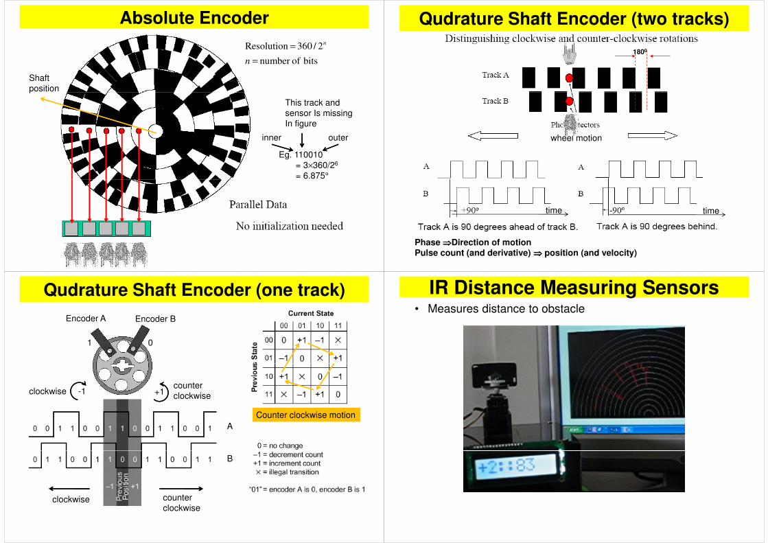
bits ofnumber
2/360 Resolution
=
=
n
n
Absolute Encoder
Shaft
position
Eg. 110010
= 3×360/26
= 6.875°
position
This track and
sensor Is missing
In figure
inner outer
= 6.875°
1800
Qudrature Shaft Encoder (two tracks)
wheel motion
Phase ⇒⇒⇒⇒Direction of motionPulse count (and derivative) ⇒⇒⇒⇒ position (and velocity)
timetime
Qudrature Shaft Encoder (one track)
Encoder B
1 0
Encoder A
+1-1
A
clockwisecounter
clockwise
Counter clockwise motion
B
counter
clockwiseclockwise
IR Distance Measuring Sensors• Measures distance to obstacle
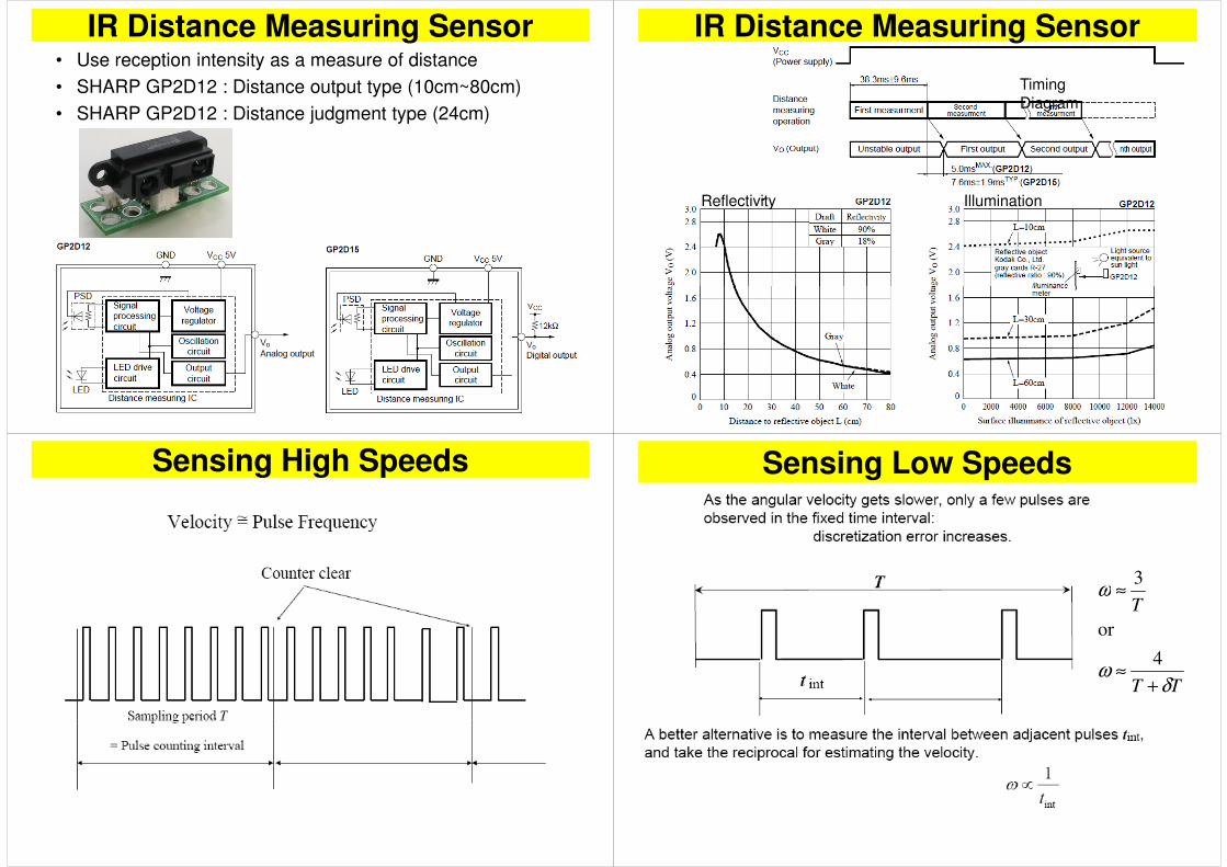
IR Distance Measuring Sensor• Use reception intensity as a measure of distance
• SHARP GP2D12 : Distance output type (10cm~80cm)
• SHARP GP2D12 : Distance judgment type (24cm)
IR Distance Measuring Sensor
TimingDiagram
IlluminationReflectivity
Sensing High Speeds Sensing Low Speeds
ω ≈3
TT
T
δω
ω
+≈
≈
4
or
3

Ultrasonic Range Sensor• 3cm ~4m, 40~60kHz
• Emits ultrasonic ping and listen to the echo
• Problems
obstacle todistancespeed sound5.0flight of time =××
• Problems
– Wide field of reception: where is the obstacle exactly??
– False echoes: ground reflection, etc..
– Not very accurate: sound speed changes on temperature and humidity
Sonar Sensor InterfacePinConfiguration
Internal resonances takes 2.38ms to decay out. Echoes can be detected
after this interval (min distance limit)
At a distance, echo becomes too weak to be detected (max distance)
Timing DiagramMode 1 (two pin)
Sonar Sensor Beam width
As frequency increase attenuation increases and beam width reduces
Beam width shouldn’t be too wide to hear false echoes. It shouldn’t be too
narrow to miss a legitimate obstacle
Narrow beam width sensors are used atop a scanning (servo) mechanisms
Robots with Ultrasonic Sensors
• Real-time Collision Avoidance