Embed Size (px)
Citation preview
(a) (b)
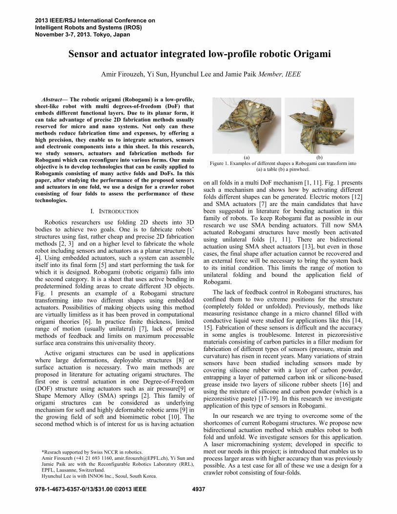
Figure 1. Examples of different shapes a Robogami can transform into (a) a table (b) a pinwheel.
Abstract— The robotic origami (Robogami) is a low-profile, sheet-like robot with multi degrees-of-freedom (DoF) that embeds different functional layers. Due to its planar form, it can take advantage of precise 2D fabrication methods usually reserved for micro and nano systems. Not only can these methods reduce fabrication time and expenses, by offering a high precision, they enable us to integrate actuators, sensors and electronic components into a thin sheet. In this research, we study sensors, actuators and fabrication methods for Robogami which can reconfigure into various forms. Our main objective is to develop technologies that can be easily applied to Robogamis consisting of many active folds and DoFs. In this paper, after studying the performance of the proposed sensors and actuators in one fold, we use a design for a crawler robot consisting of four folds to assess the performance of these technologies.
I. INTRODUCTION
Robotics researchers use folding 2D sheets into 3D bodies to achieve two goals. One is to fabricate robots’ structures using fast, rather cheap and precise 2D fabrication methods [2, 3] and on a higher level to fabricate the whole robot including sensors and actuators as a planar structure [1, 4]. Using embedded actuators, such a system can assemble itself into its final form [5] and start performing the task for which it is designed. Robogami (robotic origami) falls into the second category. It is a sheet that uses active bending in predetermined folding areas to create different 3D objects. Fig. 1 presents an example of a Robogami structure transforming into two different shapes using embedded actuators. Possibilities of making objects using this method are virtually limitless as it has been proved in computational origami theories [6]. In practice finite thickness, limited range of motion (usually unilateral) [7], lack of precise methods of feedback and limits on maximum processable surface area constrains this universality theory.
Active origami structures can be used in applications where large deformations, deployable structures [8] or surface actuation is necessary. Two main methods are proposed in literature for actuating origami structures. The first one is central actuation in one Degree-of-Freedom (DOF) structure using actuators such as air pressure[9] or Shape Memory Alloy (SMA) springs [2]. This family of origami structures can be considered as underlying mechanism for soft and highly deformable robotic arms [9] in the growing field of soft and biomimetic robot [10]. The second method which is of interest for us is having actuation
*Resrach supported by Swiss NCCR in robotics. Amir Firouzeh (+41 21 693 1160, [email protected]), Yi Sun and Jamie Paik are with the Reconfigurable Robotics Laboratory (RRL), EPFL, Lausanne, Switzerland. Hyunchul Lee is with INNO6 Inc., Seoul, South Korea.
on all folds in a multi DoF mechanism [1, 11]. Fig. 1 presents such a mechanism and shows how by activating different folds different shapes can be generated. Electric motors [12] and SMA actuators [7] are the main candidates that have been suggested in literature for bending actuation in this family of robots. To keep Robogami flat as possible in our research we use SMA bending actuators. Till now SMA actuated Robogami structures have mostly been activated using unilateral folds [1, 11]. There are bidirectional actuation using SMA sheet actuators [13], but even in those cases, the final shape after actuation cannot be recovered and an external force will be necessary to bring the system back to its initial condition. This limits the range of motion to unilateral folding and bound the application field of Robogami.
The lack of feedback control in Robogami structures, has confined them to two extreme positions for the structure (completely folded or unfolded). Previously, methods like measuring resistance change in a micro channel filled with conductive liquid were studied for applications like this [14, 15]. Fabrication of these sensors is difficult and the accuracy in some angles is troublesome. Interest in piezoresistive materials consisting of carbon particles in a filler medium for fabrication of different types of sensors (pressure, strain and curvature) has risen in recent years. Many variations of strain sensors have been studied including sensors made by covering silicone rubber with a layer of carbon powder, entrapping a layer of patterned carbon ink or silicone-based grease inside two layers of silicone rubber sheets [16] and using the mixture of silicone and carbon powder (which is a piezoresistive paste) [17-19]. In this research we investigate application of this type of sensors in Robogami.
In our research we are trying to overcome some of the shortcomes of current Robogami structures. We propose new bidirectional actuation method which enables robot to both fold and unfold. We investigate sensors for this application. A laser micromachining system; developed in specific to meet our needs in this project; is introduced that enables us to process larger areas with higher accuracy than was previously possible. As a test case for all of these we use a design for a crawler robot consisting of four-folds.
Sensor and actuator integrated low-profile robotic Origami
Amir Firouzeh, Yi Sun, Hyunchul Lee and Jamie Paik Member, IEEE
2013 IEEE/RSJ International Conference onIntelligent Robots and Systems (IROS)November 3-7, 2013. Tokyo, Japan
978-1-4673-6357-0/13/$31.00 ©2013 IEEE 4937
In next two sections, the actuator and the sensor design and their characterizations are presented. In section IV, layer by layer fabrication process is introduced and the design for the four-fold robot is presented. Then the laser micro machining instrument used in patterning different layers is introduced. In section V result of experiment on the four-fold robot is presented and performance of its components is studied. Section VI presents a conclusion of the results of this work and future steps are presented.
II. ACTUATORS
Low profile bending SMA actuators have a high compatibility with paradigm of Robogami (low profile with high torque to mass ratio). For now we affix these actuators to the structure mechanically but they can be integrated with other layers in larger sheets with smaller tiles during the fabrication process.
In what follows we present our design for bidirectional actuation using two antagonistic actuators on each fold and study the performance of this solution in theory and practice.
A. Folding Actuator Design
Here we study the maximum range of motion in a bidirectional fold with SMA actuators and design parameters affecting it. Also we present the results of thermal analysis which determine the respond time of the actuators. Previously y and z type bending actuators were proposed for Robogami structures [7]. These designs had been used because they were relatively easy to form for annealing process (actuators shape should be close to a full circle during annealing to get the complete 180o bending when they are actuated afterwards). The drawback is that these designs (and specially z type actuators) tend to twist when they are twinned. This is a serious problem in bidirectional actuation and particularly in the design suggested here, where actuators are placed side by side. So we switched to the rectangular actuators which are expected to produce a more uniform deformation and a larger torque compared to the z or y type actuators of the same size. The only problem is the forming process before annealing. For that, we need to roll the actuators nearly twice which given the diameter and actuator thickness is a rather hard process.
Here assuming simple bending model, a uniform radius of curvature along the actuators, and neglecting effects like twist in tiles we calculate the maximum available range of motion for a module with bidirectional actuation. Considering these assumptions, (1) yields the generated torque by the actuators.
,
(1)
In this equation t and w stand for thickness and width of the actuator. and are stain and stress, y is the distance from the neutral plane, R is the radius of curvature, is the length of actuator and is the bending angle. To evaluate this equation we need stress-strain data (F ε, Temp ). Here we use data from [20] for this function.
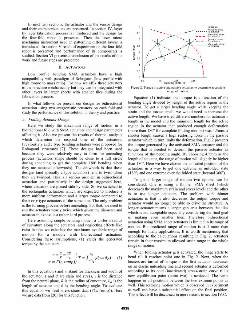
Equation (1) indicates that torque is a function of the bending angle divided by length of the active region in the actuator. To get a larger bending angle while keeping the strain and the torque small, we would need to increase the active length. We have tried different numbers for actuator’s length in the model and the minimum length for the active region in the actuator that produced enough deformation (more than 180o for complete folding motion) was 4.5mm. a shorter length causes a high restoring force in the passive actuator which in turn limits the deformation. Fig. 2 presents the torque generated by the activated SMA actuator and the torque that is needed to deform the passive actuator as functions of the bending angle. By choosing 4.5mm as the length of actuator, the range of motion will slightly be higher than 180o. Here we have chosen the annealed position of the actuators in a way to get one extreme as unfolded state (180o) and one extreme over the folded state (beyond 360o).
To get a larger range of motion two options can be considered. One is using a thinner SMA sheet (which decreases the maximum strain and stress level) and the other is to use longer actuators. The problem with thinner actuators is that it also decreases the output torque and actuator would no longer be able to drive the structure. A longer actuator means a larger gap area between the tiles which is not acceptable especially considering the final goal of making even smaller tiles. Therefore bidirectional actuation using SMA sheet actuators is limited in its range of motion. But predicted range of motion is still more than enough for many applications. It is worth mentioning that according to the calculations resulting in Fig. 2, actuators remain in their maximum allowed strain range in the whole range of motion.
When folding actuator gets activated, the hinge starts to bend till it reaches point one in Fig. 2. Next, when the heaters are turned off torque in the first actuator decreases on an elastic unloading line and second actuator is deformed according to its cold (inactivated) stress-strain curve till a new equilibrium point (point two) is achieved. The same happens in all positions between the two extreme points as well. This restoring motion which is observed in experiment as well can have a substantial effect on the final position. This effect will be discussed in more details in section IV.C.
Figure 2. Torque in active and passive actuators to determine accessible
range of motion.
22
1 1
4938
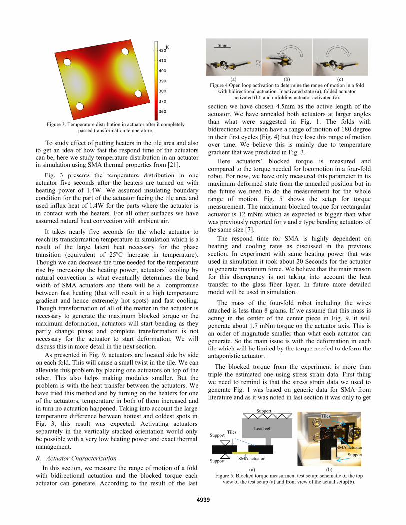
To study effect of putting heaters in the tile area and also to get an idea of how fast the respond time of the actuators can be, here we study temperature distribution in an actuator in simulation using SMA thermal properties from [21].
Fig. 3 presents the temperature distribution in one actuator five seconds after the heaters are turned on with heating power of 1.4W. We assumed insulating boundary condition for the part of the actuator facing the tile area and used influx heat of 1.4W for the parts where the actuator is in contact with the heaters. For all other surfaces we have assumed natural heat convection with ambient air.
It takes nearly five seconds for the whole actuator to reach its transformation temperature in simulation which is a result of the large latent heat necessary for the phase transition (equivalent of 25oC increase in temperature). Though we can decrease the time needed for the temperature rise by increasing the heating power, actuators’ cooling by natural convection is what eventually determines the band width of SMA actuators and there will be a compromise between fast heating (that will result in a high temperature gradient and hence extremely hot spots) and fast cooling. Though transformation of all of the matter in the actuator is necessary to generate the maximum blocked torque or the maximum deformation, actuators will start bending as they partly change phase and complete transformation is not necessary for the actuator to start deformation. We will discuss this in more detail in the next section.
As presented in Fig. 9, actuators are located side by side on each fold. This will cause a small twist in the tile. We can alleviate this problem by placing one actuators on top of the other. This also helps making modules smaller. But the problem is with the heat transfer between the actuators. We have tried this method and by turning on the heaters for one of the actuators, temperature in both of them increased and in turn no actuation happened. Taking into account the large temperature difference between hottest and coldest spots in Fig. 3, this result was expected. Activating actuators separately in the vertically stacked orientation would only be possible with a very low heating power and exact thermal management.
B. Actuator Characterization
In this section, we measure the range of motion of a fold with bidirectional actuation and the blocked torque each actuator can generate. According to the result of the last
section we have chosen 4.5mm as the active length of the actuator. We have annealed both actuators at larger angles than what were suggested in Fig. 1. The folds with bidirectional actuation have a range of motion of 180 degree in their first cycles (Fig. 4) but they lose this range of motion over time. We believe this is mainly due to temperature gradient that was predicted in Fig. 3.
Here actuators’ blocked torque is measured and compared to the torque needed for locomotion in a four-fold robot. For now, we have only measured this parameter in its maximum deformed state from the annealed position but in the future we need to do the measurement for the whole range of motion. Fig. 5 shows the setup for torque measurement. The maximum blocked torque for rectangular actuator is 12 mNm which as expected is bigger than what was previously reported for y and z type bending actuators of the same size [7].
The respond time for SMA is highly dependent on heating and cooling rates as discussed in the previous section. In experiment with same heating power that was used in simulation it took about 20 Seconds for the actuator to generate maximum force. We believe that the main reason for this discrepancy is not taking into account the heat transfer to the glass fiber layer. In future more detailed model will be used in simulation.
The mass of the four-fold robot including the wires attached is less than 8 grams. If we assume that this mass is acting in the center of the center piece in Fig. 9, it will generate about 1.7 mNm torque on the actuator axis. This is an order of magnitude smaller than what each actuator can generate. So the main issue is with the deformation in each tile which will be limited by the torque needed to deform the antagonistic actuator.
The blocked torque from the experiment is more than triple the estimated one using stress-strain data. First thing we need to remind is that the stress strain data we used to generate Fig. 1 was based on generic data for SMA from literature and as it was noted in last section it was only to get
Figure 3. Temperature distribution in actuator after it completely
passed transformation temperature.
K
(a) (b) (c) Figure 4 Open loop activation to determine the range of motion in a fold
with bidirectional actuation. Inactivated state (a), folded actuator activated (b), and unfolding actuator activated (c).
5mm
(a) (b)
Figure 5. Blocked torque measurment test setup: schematic of the top view of the test setup (a) and front view of the actual setup(b).
SMA actuator Support
Load cell
Support
Support Tiles
Support
SMA actuator
Tiles
4939
an insight on important parameters of the SMA bending actuators. So we did not expect for the model to fully concur with the experimental results. Aside from this, another reason for the large measured torque can be the higher strain level in the actuator which is caused by bigger annealed angle for the actuators. In future we study loading and unloading torque generated by SMA bending actuators in more details and a better model for describing loading and unloading curves for actuators will be presented.
III. ELASTIC CURVATURE SENSOR
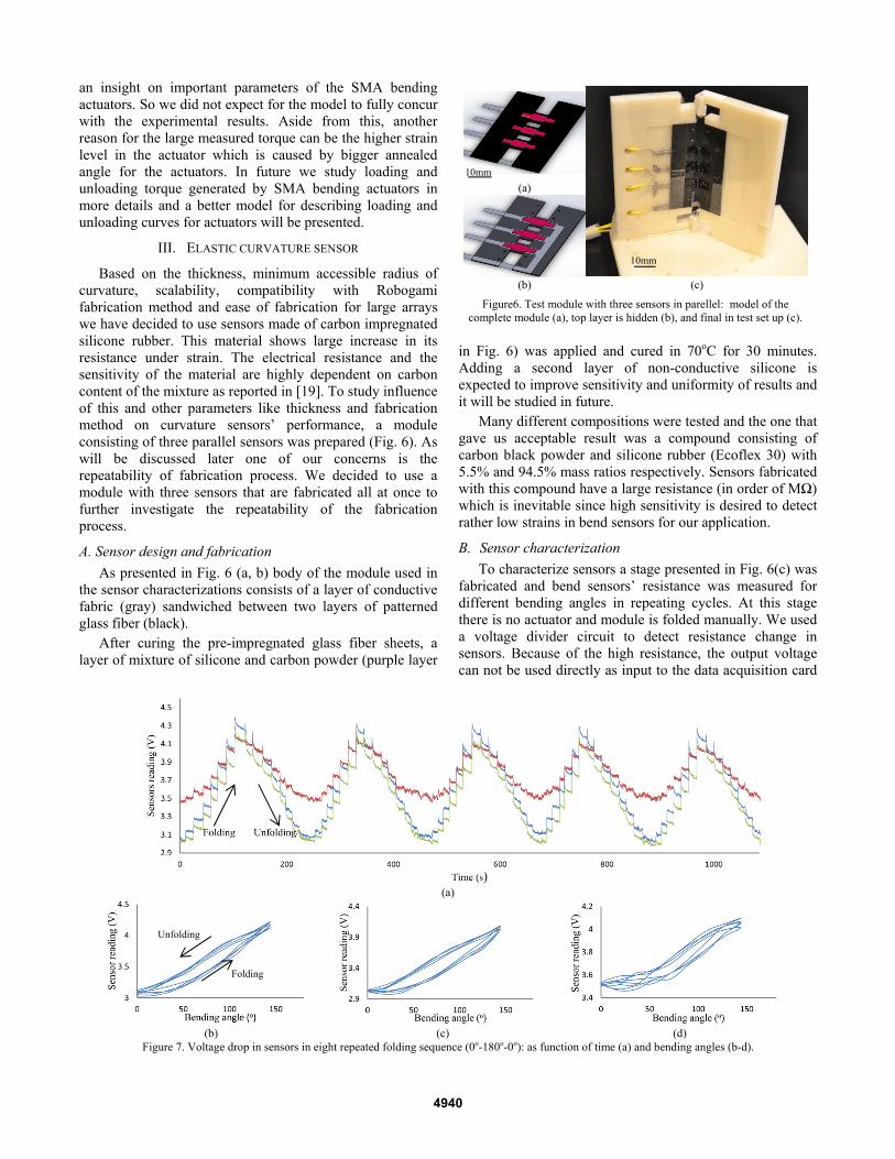
Based on the thickness, minimum accessible radius of curvature, scalability, compatibility with Robogami fabrication method and ease of fabrication for large arrays we have decided to use sensors made of carbon impregnated silicone rubber. This material shows large increase in its resistance under strain. The electrical resistance and the sensitivity of the material are highly dependent on carbon content of the mixture as reported in [19]. To study influence of this and other parameters like thickness and fabrication method on curvature sensors’ performance, a module consisting of three parallel sensors was prepared (Fig. 6). As will be discussed later one of our concerns is the repeatability of fabrication process. We decided to use a module with three sensors that are fabricated all at once to further investigate the repeatability of the fabrication process.
A. Sensor design and fabrication
As presented in Fig. 6 (a, b) body of the module used in the sensor characterizations consists of a layer of conductive fabric (gray) sandwiched between two layers of patterned glass fiber (black).
After curing the pre-impregnated glass fiber sheets, a layer of mixture of silicone and carbon powder (purple layer
in Fig. 6) was applied and cured in 70oC for 30 minutes. Adding a second layer of non-conductive silicone is expected to improve sensitivity and uniformity of results and it will be studied in future.
Many different compositions were tested and the one that gave us acceptable result was a compound consisting of carbon black powder and silicone rubber (Ecoflex 30) with 5.5% and 94.5% mass ratios respectively. Sensors fabricated with this compound have a large resistance (in order of MΩ) which is inevitable since high sensitivity is desired to detect rather low strains in bend sensors for our application.
B. Sensor characterization
To characterize sensors a stage presented in Fig. 6(c) was fabricated and bend sensors’ resistance was measured for different bending angles in repeating cycles. At this stage there is no actuator and module is folded manually. We used a voltage divider circuit to detect resistance change in sensors. Because of the high resistance, the output voltage can not be used directly as input to the data acquisition card
(a)
(b) (c) (d)
Figure 7. Voltage drop in sensors in eight repeated folding sequence (0o-180o-0o): as function of time (a) and bending angles (b-d).
Folding
Unfolding
(a)
(b) (c)
Figure6. Test module with three sensors in parellel: model of the complete module (a), top layer is hidden (b), and final in test set up (c).
10mm
10mm
4940
and we used an OpAmp to amplify the output current. Fig. 7(a) presents the voltage drop across the three sensors in time as module is repeatedly folded and unfolded with 18o increments.
All three sensors show considerable change in their resistance as the bending angle changes. The resistance of each sensor increases more than four times in the complete range of motion which makes them more sensitive comparing to previous sensors studied for this application [14]. One of the problems with conductive silicone sensors ;as previously reported in [19]; is its complicated dynamics including spikes in resistance in the beginning of deformation which always increases the resistance regardless of loading or unloading motion. Another problem is dependence of the resistance on the rate of deformation. Since here SMA actuators are used for folding and since they have rather slow respond, we are not concerned with these effects and just a static characterization will be enough for us at this stage.
Fig. 7 (a) shows the output from one sensor is not similar to the other two. This is caused by small alignment errors in assembling layers, uneven distribution of carbon particles in the conductive paste, and uneven paste distribution on the sensors. The last two are caused by high viscosity of the paste. We will use solvents or silicone based oils to dilute the mixture in order to alleviate these problems.
Fig. 7 (b-d) present the sensor readings as a function of bending angle for the module presented in Fig. 6. These measurements were carried out every 18o between the folded and unfolded states. This figure shows a clear hysteresis in all sensors. As will be discussed later this effect can cause problems and in future methods to minimize it or to somehow account for it in controller will be studied.
The average standard deviations for the first two sensors were 3.25o and 3.28o (not considering the reading for 0o and 18o which are in insensitive range of the sensors). This number for the third sensor was 7.11o which is considerably higher. Comparing with the result presented in [14] the sensors generate more accurate outputs. It is worth mentioning that the main advantage of the conductive silicone sensors in comparison to other methods is their ease of fabrication and possibility of scaling.
C. Feedback control of Robogami using soft sensor
Here we investigate performance of the proposed sensor on an origami module with bidirectional actuation by
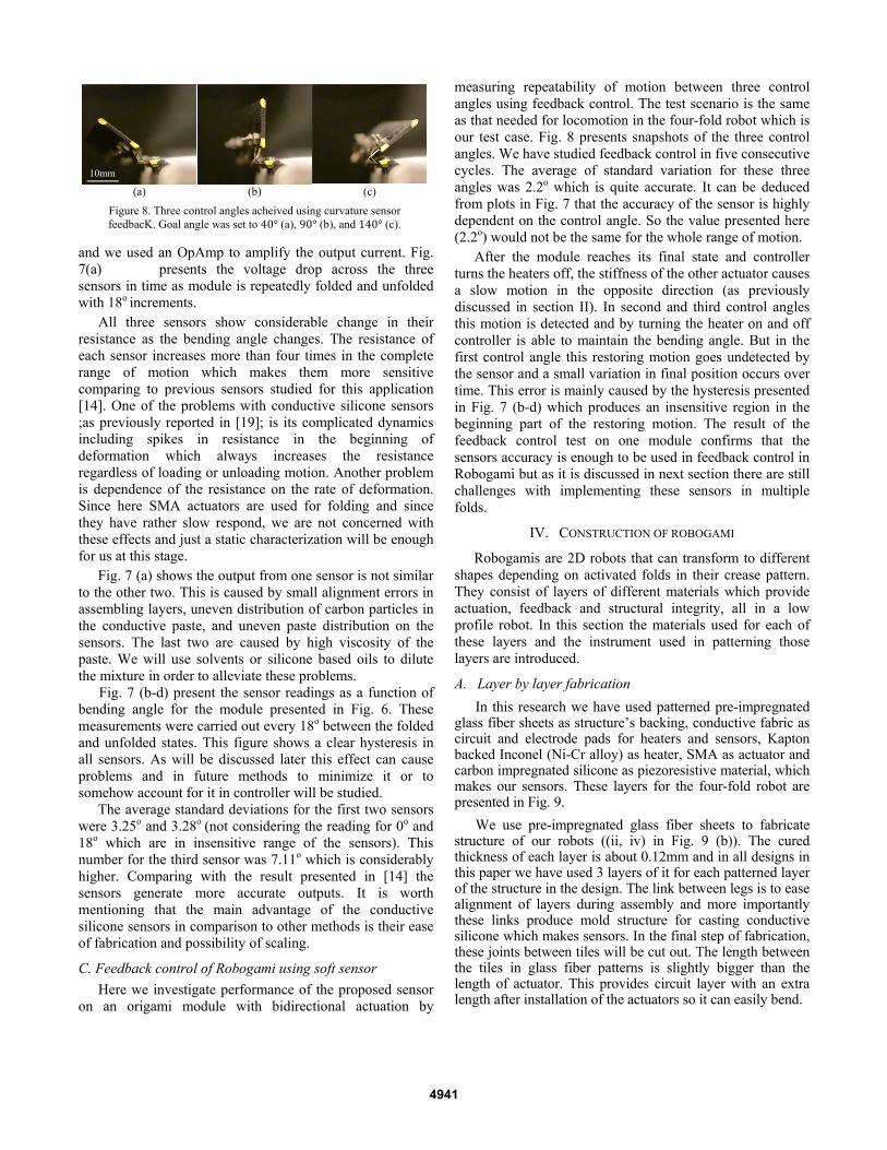
measuring repeatability of motion between three control angles using feedback control. The test scenario is the same as that needed for locomotion in the four-fold robot which is our test case. Fig. 8 presents snapshots of the three control angles. We have studied feedback control in five consecutive cycles. The average of standard variation for these three angles was 2.2o which is quite accurate. It can be deduced from plots in Fig. 7 that the accuracy of the sensor is highly dependent on the control angle. So the value presented here (2.2o) would not be the same for the whole range of motion.
After the module reaches its final state and controller turns the heaters off, the stiffness of the other actuator causes a slow motion in the opposite direction (as previously discussed in section II). In second and third control angles this motion is detected and by turning the heater on and off controller is able to maintain the bending angle. But in the first control angle this restoring motion goes undetected by the sensor and a small variation in final position occurs over time. This error is mainly caused by the hysteresis presented in Fig. 7 (b-d) which produces an insensitive region in the beginning part of the restoring motion. The result of the feedback control test on one module confirms that the sensors accuracy is enough to be used in feedback control in Robogami but as it is discussed in next section there are still challenges with implementing these sensors in multiple folds.
IV. CONSTRUCTION OF ROBOGAMI
Robogamis are 2D robots that can transform to different shapes depending on activated folds in their crease pattern. They consist of layers of different materials which provide actuation, feedback and structural integrity, all in a low profile robot. In this section the materials used for each of these layers and the instrument used in patterning those layers are introduced.
A. Layer by layer fabrication
In this research we have used patterned pre-impregnated glass fiber sheets as structure’s backing, conductive fabric as circuit and electrode pads for heaters and sensors, Kapton backed Inconel (Ni-Cr alloy) as heater, SMA as actuator and carbon impregnated silicone as piezoresistive material, which makes our sensors. These layers for the four-fold robot are presented in Fig. 9.
We use pre-impregnated glass fiber sheets to fabricate structure of our robots ((ii, iv) in Fig. 9 (b)). The cured thickness of each layer is about 0.12mm and in all designs in this paper we have used 3 layers of it for each patterned layer of the structure in the design. The link between legs is to ease alignment of layers during assembly and more importantly these links produce mold structure for casting conductive silicone which makes sensors. In the final step of fabrication, these joints between tiles will be cut out. The length between the tiles in glass fiber patterns is slightly bigger than the length of actuator. This provides circuit layer with an extra length after installation of the actuators so it can easily bend.
10mm (a) (b) (c)
Figure 8. Three control angles acheived using curvature sensor feedbacK. Goal angle was set to 40° (a), 90° (b), and 140° (c).
10mm
4941
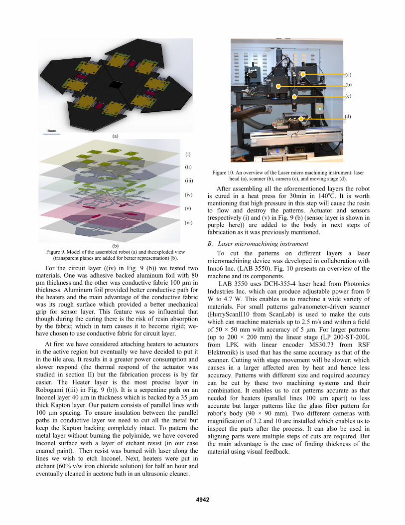
For the circuit layer ((iv) in Fig. 9 (b)) we tested two materials. One was adhesive backed aluminum foil with 80 µm thickness and the other was conductive fabric 100 µm in thickness. Aluminum foil provided better conductive path for the heaters and the main advantage of the conductive fabric was its rough surface which provided a better mechanical grip for sensor layer. This feature was so influential that though during the curing there is the risk of resin absorption by the fabric; which in turn causes it to become rigid; we- have chosen to use conductive fabric for circuit layer.
At first we have considered attaching heaters to actuators in the active region but eventually we have decided to put it in the tile area. It results in a greater power consumption and slower respond (the thermal respond of the actuator was studied in section II) but the fabrication process is by far easier. The Heater layer is the most precise layer in Robogami ((iii) in Fig. 9 (b)). It is a serpentine path on an Inconel layer 40 µm in thickness which is backed by a 35 µm thick Kapton layer. Our pattern consists of parallel lines with 100 µm spacing. To ensure insulation between the parallel paths in conductive layer we need to cut all the metal but keep the Kapton backing completely intact. To pattern the metal layer without burning the polyimide, we have covered Inconel surface with a layer of etchant resist (in our case enamel paint). Then resist was burned with laser along the lines we wish to etch Inconel. Next, heaters were put in etchant (60% v/w iron chloride solution) for half an hour and eventually cleaned in acetone bath in an ultrasonic cleaner.
After assembling all the aforementioned layers the robot is cured in a heat press for 30min in 140oC. It is worth mentioning that high pressure in this step will cause the resin to flow and destroy the patterns. Actuator and sensors (respectively (i) and (v) in Fig. 9 (b) (sensor layer is shown in purple here)) are added to the body in next steps of fabrication as it was previously mentioned.
B. Laser micromachining instrument
To cut the patterns on different layers a laser micromachining device was developed in collaboration with Inno6 Inc. (LAB 3550). Fig. 10 presents an overview of the machine and its components.
LAB 3550 uses DCH-355-4 laser head from Photonics Industries Inc. which can produce adjustable power from 0 W to 4.7 W. This enables us to machine a wide variety of materials. For small patterns galvanometer-driven scanner (HurryScanII10 from ScanLab) is used to make the cuts which can machine materials up to 2.5 m/s and within a field of 50 × 50 mm with accuracy of 5 µm. For larger patterns (up to 200 × 200 mm) the linear stage (LP 200-ST-200L from LPK with linear encoder MS30.73 from RSF Elektronik) is used that has the same accuracy as that of the scanner. Cutting with stage movement will be slower; which causes in a larger affected area by heat and hence less accuracy. Patterns with different size and required accuracy can be cut by these two machining systems and their combination. It enables us to cut patterns accurate as that needed for heaters (parallel lines 100 µm apart) to less accurate but larger patterns like the glass fiber pattern for robot’s body (90 × 90 mm). Two different cameras with magnification of 3.2 and 10 are installed which enables us to inspect the parts after the process. It can also be used in aligning parts were multiple steps of cuts are required. But the main advantage is the ease of finding thickness of the material using visual feedback.
(a)
(b) Figure 9. Model of the assembled robot (a) and theexploded view
(transparent planes are added for better representation) (b).
(i)
(ii)
(iii)
(iv)
(v)
(vi)
10mm
Figure 10. An overview of the Laser micro machining instrument: laser
head (a), scanner (b), camera (c), and moving stage (d).
(a)
(b)
(c)
(d)
4942
V. FOUR-FOLD ROBOT PROTOTYPE
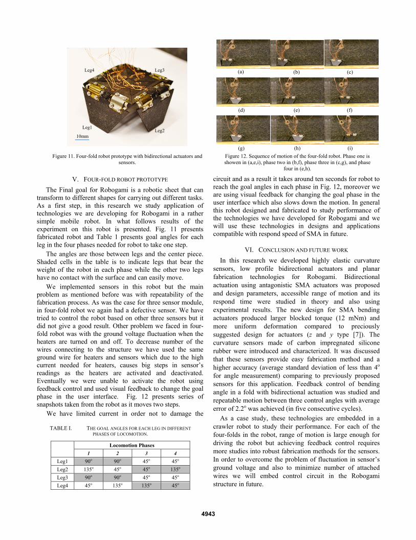
The Final goal for Robogami is a robotic sheet that can transform to different shapes for carrying out different tasks. As a first step, in this research we study application of technologies we are developing for Robogami in a rather simple mobile robot. In what follows results of the experiment on this robot is presented. Fig. 11 presents fabricated robot and Table 1 presents goal angles for each leg in the four phases needed for robot to take one step.
The angles are those between legs and the center piece. Shaded cells in the table is to indicate legs that bear the weight of the robot in each phase while the other two legs have no contact with the surface and can easily move.
We implemented sensors in this robot but the main problem as mentioned before was with repeatability of the fabrication process. As was the case for three sensor module, in four-fold robot we again had a defective sensor. We have tried to control the robot based on other three sensors but it did not give a good result. Other problem we faced in four-fold robot was with the ground voltage fluctuation when the heaters are turned on and off. To decrease number of the wires connecting to the structure we have used the same ground wire for heaters and sensors which due to the high current needed for heaters, causes big steps in sensor’s readings as the heaters are activated and deactivated. Eventually we were unable to activate the robot using feedback control and used visual feedback to change the goal phase in the user interface. Fig. 12 presents series of snapshots taken from the robot as it moves two steps.
We have limited current in order not to damage the
circuit and as a result it takes around ten seconds for robot to reach the goal angles in each phase in Fig. 12, moreover we are using visual feedback for changing the goal phase in the user interface which also slows down the motion. In general this robot designed and fabricated to study performance of the technologies we have developed for Robogami and we will use these technologies in designs and applications compatible with respond speed of SMA in future.
VI. CONCLUSION AND FUTURE WORK
In this research we developed highly elastic curvature sensors, low profile bidirectional actuators and planar fabrication technologies for Robogami. Bidirectional actuation using antagonistic SMA actuators was proposed and design parameters, accessible range of motion and its respond time were studied in theory and also using experimental results. The new design for SMA bending actuators produced larger blocked torque (12 mNm) and more uniform deformation compared to preciously suggested design for actuators (z and y type [7]). The curvature sensors made of carbon impregnated silicone rubber were introduced and characterized. It was discussed that these sensors provide easy fabrication method and a higher accuracy (average standard deviation of less than 4o for angle measurement) comparing to previously proposed sensors for this application. Feedback control of bending angle in a fold with bidirectional actuation was studied and repeatable motion between three control angles with average error of 2.2o was achieved (in five consecutive cycles).
As a case study, these technologies are embedded in a crawler robot to study their performance. For each of the four-folds in the robot, range of motion is large enough for driving the robot but achieving feedback control requires more studies into robust fabrication methods for the sensors. In order to overcome the problem of fluctuation in sensor’s ground voltage and also to minimize number of attached wires we will embed control circuit in the Robogami structure in future.
Figure 12. Sequence of motion of the four-fold robot. Phase one is showen in (a,e,i), phase two in (b,f), phase three in (c,g), and phase
four in (e,h).
(a) (b) (c)
(d) (e) (f)
(g) (h) (i)
TABLE I. THE GOAL ANGLES FOR EACH LEG IN DIFFERENT PHASES OF LOCOMOTION.
Locomotion Phases
1 2 3 4
Leg1 90o 90o 45o 45o
Leg2 135o 45o 45o 135o
Leg3 90o 90o 45o 45o
Leg4 45o 135o 135o 45o
Figure 11. Four-fold robot prototype with bidirectional actuators and sensors.
10mm
Leg1
Leg3 Leg4
Leg2
4943
ACKNOWLEDGMENT
This research is supported by Swiss National Centers for Competence in Research (NCCR) in Robotics.
REFERENCES [1] J. Paik, B. A. D. Rus, and R. J. Wood, "Robotic origamis: self-
morphing modular robots," presented at the 2nd Int. Conf. on Morphological Computation, Venice, Italy, 2011.
[2] C. D. Onal, R. J. Wood, and D. Rus, "Towards printable robotics: Origami-inspired planar fabrication of three-dimensional mechanisms," in on Robotics and Automation (ICRA), 2011 IEEE International Conference, 2011, pp. 4608-4613.
[3] M. Noh, S.-W. Kim, S. An, J.-S. Koh, and K.-J. Cho, "Flea-inspired catapult mechanism for miniature jumping robots," Robotics, IEEE Transactions on, vol. 28, pp. 1007-1018, 2012.
[4] E. Hawkes, B. An, N. M. Benbernou, H. Tanaka, S. Kim, E. D. Demaine, D. Rus, and R. J. Wood, "Programmable matter by folding," Proceedings of the National Academy of Sciences, June 28, 2010 2010.
[5] S. Felton, M. Tolley, C. Onal, D. Rus, and R. Wood, "Robot Self-Assembly by Folding: A Printed Inchworm Robot," presented at the on Robotics and Automation (ICRA), 2013 IEEE International Conference, 2013.
[6] N. Benbernou, E. D. Demaine, M. L. Demaine, and A. Ovadya, "A universal crease pattern for folding orthogonal shapes," presented at the eprint arXiv, 2009.
[7] J. Paik, E. Hawkes, and R. Wood, "A novel low-profile shape memory alloy torsional actuator," Smart Materials and Structures, vol. 19, p. 125014, 2010.
[8] K. Miura, "Method of packaging and deployment of large membranes in space," in in Proc. 31st Congr. Int. Astronautics Federation, 1980, pp. 1-10.
[9] R. V. Martinez, C. R. Fish, X. Chen, and G. M. Whitesides, "Elastomeric origami programmable paper-elastomer composites as pneumatic actuators," Advanced Functional Material, vol. 22, pp. 1376-1384, 2012.
[10] M. Follador, M. Cianchetti, and C. Laschi, "Development of the functional unit of a completely soft octopus-like robotic arm," in Biomedical Robotics and Biomechatronics (BioRob), 2012 4th IEEE RAS & EMBS International Conference on, 2012, pp. 640-645.
[11] B. An and D. Rus, "Programming and controlling self-folding robots," in Robotics and Automation (ICRA), 2012 IEEE International Conference on, 2012, pp. 3299-3306.
[12] T. Kano, Y. Watanabe, and A. Ishiguro, "SheetBot: A magic carpet that enables scaffold-based locomotion," in Intelligent Robots and Systems (IROS), 2012 IEEE/RSJ International Conference on, 2012, pp. 1434-1439.
[13] J. K. Paik and R. J. Wood, "A bidirectional shape memory alloy folding actuator," Smart Materials and Structures, vol. 21, p. 065013, 2012.
[14] J. K. Paik, R. K. Kramer, and R. J. Wood, "Stretchable circuits and sensors for robotic origami," in Intelligent Robots and Systems (IROS), 2011 IEEE/RSJ International Conference on, 2011, pp. 414-420.
[15] R. K. Kramer, C. Majidi, R. Sahai, and R. J. Wood, "Soft curvature sensors for joint angle proprioception," in Intelligent Robots and Systems (IROS), 2011 IEEE/RSJ International Conference on, 2011, pp. 1919-1926.
[16] K. Kure, T. Kanda, K. Suzumori, and S. Wakimoto, "Intelligent FMA using flexible displacement sensor with paste injection," in Robotics and Automation, 2006. ICRA 2006. Proceedings 2006 IEEE International Conference on, 2006, pp. 1012-1017.
[17] S. Rosset and H. Shea, "Flexible and stretchable electrodes for dielectric elastomer actuators," Applied Physics A, vol. 110, pp. 281-307, 2013/02/01 2013.
[18] T. Yamada, Y. Hayamizu, Y. Yamamoto, Y. Yomogida, A. Izadi-Najafabadi, D. N. Futaba, and K. Hata, "A stretchable carbon nanotube strain sensor for human-motion detection," Nat Nano, vol. 6, pp. 296-301, 2011.
[19] M. A. Lacasse, V. Duchaine, and C. Gosselin, "Characterization of the electrical resistance of carbon-black-filled silicone: Application to a flexible and stretchable robot skin," in Robotics and Automation
(ICRA), 2010 IEEE International Conference on, 2010, pp. 4842-4848.
[20] Z. K. Lu and G. J. Weng, "A self-consistent model for the stress–strain behavior of shape-memory alloy polycrystals," Acta Materialia, vol. 46, pp. 5423-5433, 1998.
[21] . Nitinol Technical Properties. Available: http://jmmedical.com/resources/221/Nitinol-Technical-Properties.html
4944