Embed Size (px)
Citation preview

CHEMICAL ENGINEERING TRANSACTIONS
VOL. 52, 2016
A publication of
The Italian Association of Chemical Engineering Online at www.aidic.it/cet
Guest Editors: Petar Sabev Varbanov, Peng-Yen Liew, Jun-Yow Yong, Jiří Jaromír Klemeš, Hon Loong Lam Copyright © 2016, AIDIC Servizi S.r.l.,
ISBN 978-88-95608-42-6; ISSN 2283-9216
Sensitivity Analysis of Radiative Heat Loading to Tube Coil
with Geometric Imperfections
Jiří Hájek, Zdeněk Jegla
Brno University of Technology, Faculty of Mechanical Engineering, Institute of Process and Environmental Engineering,
Technická 2, 616 69 Brno, Czech Republic
The tube coil in real fired heater after some use deviates from the ideal designed geometry. The tubes slightly
bend and depending on the quality of the hooks on which they are suspended, they may also shift from their
design positions. Such behaviour is not accounted for in the design procedures and it is therefore important to
assess the impact of the geometry imperfections on heat loads to the tubes. It has been recently shown in
(Jegla et al., 2015) that geometry imperfections may contribute to increased heat flux nonuniformity, but a
systematic treatment of the impact of tube position deviations has not been reported so far.
The modelling methodology adopted in the present work is based on idealized flame and refractory wall
behaviour, which allows to investigate the radiative heat loading of the tube coil surface. The model conditions
are in essence the same as in the landmark work of (Hottel and Sarofim, 1967). Historically the approach to
solve the radiative heat transfer equation was to idealise geometries and then apply zonal method. Results
were obtained by analytic solution of the heat exchange factor integrals. The only difference here is that we
apply modern numerical methods that make it possible to analyse more complex geometries. The geometries
analysed are 2-D cuts of a row of tubes. One of the tubes is always displaced to simulate tube coil
deformations. The main aim of the study is to cover scenarios with one deformed tube in a row of ideally
placed ones.
The results cover an array of geometric configurations that follow from the typical tube coil arrangements used
in fired heaters. Namely, the geometry of tube bends (U-turns) has two basic designs, denoted as “short-
radius” and “long-radius”. These two design options define the two baseline configurations. Cylindrical furnace
geometry is considered.
1. Introduction
The aim of this contribution is to make design calculations of tubular furnaces more reliable by providing
insight into how deformations of tube coil influence heat flux uniformity. Considering the fact that design
practices in this specific industry (Li et al., 2015) are very conservative and adhere to solutions that are proven
by many years of operation, it is imperative to provide strong irrefutable evidence. It is also very important to
relate any results to the standard design calculation methodology, to facilitate meaningful interpretation by
furnace designers. Consequently, it is necessary to start this paper by a brief introduction of the standard
design practices, followed by a description of the applied method and overview of results. In the conclusion,
general observations are drawn from the results.
1.1 Tubular furnace and its role in production processes Fired heaters are complex units for the exchange of heat, widely used in chemical, petrochemical and refining
plants. They provide to the process necessary heat supply by combustion of various fuels. They constitute an
independent energy source and thus are used in demanding production technologies typically as a final
process unit (following process heat exchangers). The processed stream is heated to a level required by a key
processing unit of the production technology, which is mostly a distillation column or reactor, etc.
DOI: 10.3303/CET1652126
Please cite this article as: Hájek J., Jegla Z., 2016, Sensitivity analysis of radiative heat loading to tube coil with geometric imperfections, Chemical Engineering Transactions, 52, 751-756 DOI:10.3303/CET1652126
751

1.2 Types and designs of tubular furnaces All contemporary installations of fired heaters belong to one of two basic types, cabin (shaft) and cylindrical, as
illustrated in Figure 1. Cabin type furnaces are used for high thermal duties, whereas cylindrical furnaces are
preferred for lower thermal duties. In spite of this apparent similarity, each unit is custom-made and tailored for
maximum compatibility with the specific process.
Tubes of Convection
Section
Tubes of Radiant
Chamber
Burners Burners
Figure 1: Left - cabin type, right – vertical cylindrical type (adapted from (Jegla, 2013))
Each of these furnace types consists of two main parts – combustion chamber (radiation section) and
convective part (convective section). The names imply the dominating heat transfer mechanism in the two
parts – radiation and convection. Process medium flows inside of a tubular system, which forms the heat
exchanger. By changing the shape and configuration of tubes in radiation and convective parts of the furnace,
multiple heater design types are formed that satisfy specific demands and conditions of each process.
1.3 Design of tube coils
The tube system of a furnace is mostly split into several branches (streams), depending on the amount of the
process fluid. The process fluid first goes through the convective section and then the radiation section, where
it reaches its target temperature required by the following key processing unit. In cabin type furnaces, the tube
system is typically placed horizontally along the walls, whereas in vertical cylindrical furnaces the tubes are
typically vertical, although different configurations are also possible.
The common feature of most designs is that they are made of straight tubes connected by welded 180° or 90°
tube bends. The bends are manufactured mostly in two standardised forms, so-called short (SR) and large
radius (LR) bends. The basic short radius bend is distinguished by a centre radius of about 1 × 𝑑, where 𝑑 is
the tube diameter. The radius of LR bends is about 1.5 × 𝑑. A more precise specification of tube distance in
furnace applications is usually given by a fraction of tube pitch (𝑠) over tube diameter (𝑑). This parameter has
a value of approximately 1.8 for SR bends and 2.7 for LR bends.
In some applications, tubes are arranged helically, which provides a complete freedom in terms of tube pitch.
Such designs may be met both in cabin and cylindrical type heaters. Optimum pitch (and slope) of helical tube
system may thus be identified for each specific application.
1.4 Deformations of tube coils
The harsh conditions in an operating fired heater make it difficult to maintain perfect design geometry of the
tube coils during the whole furnace lifetime. It is quite common that tubes are deformed both temporarily and
permanently due to the repeated joint action of thermal and mechanical loading. The ideal, precisely optimised
tube coil geometry is therefore transformed into a real, imperfect one, which contains many individual
deformations.
Dominating among these deformations are tube displacements, which means that the cylindrical tube cross-
sections is retained (thanks to the action of large internal pressure), but the whole tube is bent and moved
outside of its design position. In instances where the tube coil retains overall symmetry and periodicity, there
these displacements are not very important, as tube pitch and wall-normal distance are not changed
significantly. In contrast to that, the real deformations are often nonlinear and visibly impact symmetry and
752
periodicity of the tube coil, as the displacements of individual tubes have a different magnitude. The pitch and
wall-normal distance of a tube is then significantly different from the design geometry.
As radiative heat transfer is very much a function of system geometry, any such displacement causes a
change of the local heat loading. The purpose of this work is therefore to analyse the effect of individual tube
deformations on the magnitude of nonuniformity of heat transfer rates.
1.5 Standard design calculations Well-established methodology of calculating radiative heat transfer in the radiation section of tubular furnaces
is build up on the assumption of perfectly stirred reactor, see e.g. (Hewitt et al., 1994). The whole design
procedure is usually performed along the guidelines of the standard API 560 (API, 2007). The standard mainly
provides limits for numerous design parameters, but tube coil deformations are not considered.
To outline the standardised methodology, it is possible to say that it relies on several tabulated parameters,
which describe nonuniformity of the heat fluxes on the tube coil surface. These so-called factors of heat flux
density variation serve to determine an estimate of maximum local heat flux in the radiation section, which is a
key design parameter of tubular furnaces. As shown recently in a detailed computational analysis (Jegla et al.,
2015), the factors of heat flux density variation do not cover all phenomena that may have impact on the
nonuniformity of heat flux distribution.
The said coefficients (factors) are however deeply rooted in the design practice and therefore results of any
detailed analysis should be transformed into these coefficients, to enable practical adoption.
1.6 Motivation The magnitude of heat flux nonuniformity is a key design parameter, which plays a pivotal role in fired heater
design, as outlined above. In this context it becomes clear that it is important to analyse systematically the
possible impact of tube coil deformations on the distribution of heat flux to the tube walls. This need was one
of the findings in a previous study (Jegla et al. 2015), which established a qualitative correlation of heat flux
density with tube deformations, although flow pattern of flue gas in the fired heater was identified as the major
source of heat flux nonuniformity. Standardised design calculations contain numerous simplifications, which
make precise and robust predictions of maximum heat flux to the process fluid difficult. One of these
assumptions is the reliance on nominal design geometry and this is a second motivation for the present work.
2. Modelling methodology
The choice of modelling methodology in this study has been motivated (similarly as other aspects noted
above) by adherence to the standardised principles of design calculations for fired heaters. Specifically, the
correlations for heat flux density variations, namely the circumferential heat flux variability factor, have been
historically obtained using zonal method. Therefore, the present work utilised also a version of zonal method,
although in a modern implementation. Simplifying assumptions adopted in the computations are the same as
in those long-standing results. A verification of the present 2D modelling methodology has been documented
in a previous publication (Jegla et al., 2015).
In this work, we analyse the impact of single tube displacement on the tube circumference heat flux variation
factor in a parametric study. The computations were performed by S2S radiative heat transfer model as
implemented in a commercial code ANSYS® Fluent, Release16.2.
2.1 Simplified radiative heat transfer simulation
The computational model consists mainly of three basic zones that correspond to the model boundary
conditions: heat source (flame), adiabatic wall (refractory) and heat sink (tubes). The radiative heat transfer
model does not take into account participating medium, which makes its results only approximate in
comparison with today’s state-of-art radiative heat transfer models. As explained above however, the same
methodology has been used in the early work of (Hottel and Sarofim, 1967). Note that the flame is
represented by a hot surface with uniform temperature and that tubes have a prescribed inner surface
temperature, which is also uniform and the same in all tubes in the model. Specific temperature values are not
important, as the output from the model is normalized and only relative local differences of heat flux density
are analysed. The model does not include the effects of other means of heat transfer (convective and
conductive).
The impact of radiative heat transfer from the refractory (historically denoted as re-radiation) has been
included in the model by assuming diffuse reflection from the refractory. This means that all irradiation is
reflected, but the reflected radiative energy is distributed randomly (uniformly) across the whole half-space
solid angle. Tubes on the other hand have been modelled as ideal black bodies (emissivity equal to 1).
753

2.2 Model geometry Geometry of the model is formed by a horizontal cross-section of several tubes, the middle one of which is
displaced both in wall-normal direction and tangentially along the wall. Dimensions of the furnace are the
same as in (Jegla et al., 2015), notably outside tube diameter is 0.194 m, furnace diameter is 7 m and nominal
tube coil diameter is 6.418 m. A pre-defined matrix of displacements has been constructed for two baseline
configurations, one with SR bends and the other with LR bends. The simulated row of tubes is not a full circle,
but instead six tubes in nominal positions have been included in the geometry on both sides of the central
displaced tube. This was found sufficient in a preliminary sensitivity analysis. Symmetry condition was
imposed on the tangential boundary of the model, as illustrated in Figure 2.
Figure 2: 2D model geometry in the case with SR bends
The displacements of the middle tube have been limited to 80 % of tube diameter in the radial direction and
3° in the tangential direction for the SR case. In the LR case, the maximum tangential displacement was 6°
due to the larger pitch of tubes in that case, while radial were the same as for the SR case. Note that the tube
displacements have been limited with caution to avoid direct contact of neighbouring tubes or tube and
refractory. The shortest distance between the displaced tube and its neighbour or the refractory is about 20 %
of tube diameter.
2.3 Computational grid The computational grid was created from unstructured quadrilateral cells with a uniform cell size of about
1/30 × 𝑑 , which has been established in a preliminary grid independence study as fully satisfactory. Similarly,
all numerical and convergence parameters of the computational model have been set to conservative values
assuring full convergence and independence on the numerical model settings.
3. Results and discussion
The results of the two parametric studies for SR and LR tube bends have confirmed that severe
displacements may indeed lead to significant increase of tube circumferential heat flux variability factor. As
expected, any displacement of one of the tubes leads to an increase of the circumferential heat flux variability
factor, as documented in Figures 3 and 4. In order to interpret the results, it is important to understand the true
meaning of the reported data. The first step in post processing of the simulation results was the calculation of
peak and mean heat flux on each of the 13 tubes in the model as shown in Figure 2. Tube circumferential heat
flux variability factor is the ratio of these two values. So each tube in a concrete geometry has its own value of
the factor. Identification of the tube with maximum heat flux variability is not important, much more significant
is the maximum value of the factor in a given furnace geometry. The displayed variable in Figures 3 and 4 is
thus the maximum of tube circumference heat flux variability factors, plotted on a matrix of displacements for
the corresponding case as shown by x marks.
Note that it is interesting to distinguish two slightly different definitions of the tube circumferential heat flux
variability factor, namely a local and a global one. The local factor is defined as the ratio of peak heat flux on
an individual tube to a mean heat flux on the same individual tube. In contrast to that, the global factor is
defined as the ratio of peak heat flux on an individual tube to the mean heat flux over all tubes. The global
factor thus better describes the peak heat flux one may find in a fired heater. The local factor describes heat
flux nonuniformity on individual tubes.
The least impact on heat flux uniformity is clearly caused by a tube being displaced towards the wall. It is
however important to note, that a slight displacement of a tube in any direction does not cause a steep rise of
the heat flux nonuniformity. Both parametric studies illustrated by Figures 3 and 4 show the lowest sensitivity
of the circumferential heat flux variability factor in the vicinity of the tube nominal position (while displacements
keep below a fraction of tube diameter).
754

a)
b)
Figure 3: Contour plot of maximum tube circumferential heat flux variability factor across the matrix of middle
tube displacements for the SR case a) local variability factor, b) global variability factor
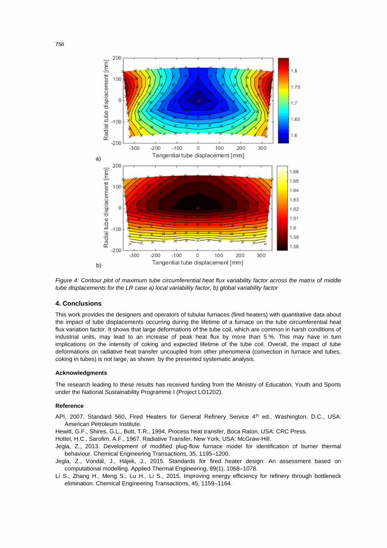
In contrast to that, the worst impact has been predicted for cases where a tube is moved both tangentially
towards its neighbour and simultaneously toward the flame. The maximum predicted increase of the global
circumferential heat flux variability factor was about 5% for both the SR and LR cases. In terms of the local
variability factor, an increase of about 14 % for the SR case and about 18 % for the LR case was observed.
Closer inspection of the data shows that the most affected tube is the displaced tube when it is moved towards
the flame. When the displaced tube is moved towards the refractory, then the worst affected tube is the
neighbour tube towards which the displaced one is shifted.
755
a)
b)
Figure 4: Contour plot of maximum tube circumferential heat flux variability factor across the matrix of middle
tube displacements for the LR case a) local variability factor, b) global variability factor
4. Conclusions
This work provides the designers and operators of tubular furnaces (fired heaters) with quantitative data about
the impact of tube displacements occurring during the lifetime of a furnace on the tube circumferential heat
flux variation factor. It shows that large deformations of the tube coil, which are common in harsh conditions of
industrial units, may lead to an increase of peak heat flux by more than 5 %. This may have in turn
implications on the intensity of coking and expected lifetime of the tube coil. Overall, the impact of tube
deformations on radiative heat transfer uncoupled from other phenomena (convection in furnace and tubes,
coking in tubes) is not large, as shown by the presented systematic analysis.
Acknowledgments
The research leading to these results has received funding from the Ministry of Education, Youth and Sports
under the National Sustainability Programme I (Project LO1202).
Reference
API, 2007. Standard 560, Fired Heaters for General Refinery Service 4th ed., Washington, D.C., USA:
American Petroleum Institute.
Hewitt, G.F., Shires, G.L., Bott, T.R., 1994. Process heat transfer, Boca Raton, USA: CRC Press.
Hottel, H.C., Sarofim, A.F., 1967. Radiative Transfer, New York, USA: McGraw-Hill.
Jegla, Z., 2013. Development of modified plug-flow furnace model for identification of burner thermal
behaviour. Chemical Engineering Transactions, 35, 1195–1200.
Jegla, Z., Vondál, J., Hájek, J., 2015. Standards for fired heater design: An assessment based on
computational modelling. Applied Thermal Engineering, 89(1), 1068–1078.
Li S., Zhang H., Meng S., Lu H., Li S., 2015. Improving energy efficiency for refinery through bottleneck
elimination. Chemical Engineering Transactions, 45, 1159–1164.
756


![Model-Based Reinforcement Learning in Robotics...Model-Free Example Rainbow Algorithm [2] 1𝑓= 1 60 𝑠 200.000.000𝑓=…=925,925ℎ=38,58 Not feasible in robotics! MODEL-BASED](https://img.pdfslide.us/doc/110x75/5e7d24c49122c672583e89c1/model-based-reinforcement-learning-in-robotics-model-free-example-rainbow-algorithm.jpg)