Embed Size (px)
Citation preview
Sensistor ILS500 FTracer Gas Filler
Operating Instructions
Pub
licat
ion:
INFI
CO
N A
B -
ninp
69e1
-a (1
204)
- A
ll in
form
atio
n ca
n be
mod
ified
with
out p
ior n
otic
e
EN
2 OP-ILS500 F-EN-201204
1. General .....................................................................................................................................32. Safety ........................................................................................................................................43. Contents of delivery ................................................................................................................54. Technical Description .............................................................................................................6
4.1 Design .................................................................................................................................64.2. Test Cycle ...........................................................................................................................7
5. Installation................................................................................................................................85.1 Placement of ILS500 F ........................................................................................................85.2 Electrical Connections .........................................................................................................95.3 Pneumatic Connections ....................................................................................................105.4 Compressed Air .................................................................................................................115.5 Tracer Gas Supply ............................................................................................................115.6 Pressure Regulator ...........................................................................................................115.7 Exhaust .............................................................................................................................125.8 Fresh Air ............................................................................................................................13
6. Controls ..................................................................................................................................146.1 Buttons/lamps ...................................................................................................................146.2 Main display ......................................................................................................................15
7. Menu System .........................................................................................................................167.1 Menus ...............................................................................................................................167.2 Quick Setup .......................................................................................................................187.3 Standard Setup .................................................................................................................197.4 Advanced Setup ................................................................................................................237.5 Parameter Index ................................................................................................................43
8. Fill Cycle Details ....................................................................................................................458.1 Detailed Description of Fill Cycle ......................................................................................468.2 Stand by ............................................................................................................................488.3 Tooling Connection ............................................................................................................498.4 Pre Evacuation ..................................................................................................................508.5 Gross Leak Test ................................................................................................................528.6 Tracer Gas Filling ..............................................................................................................548.7 Blockage Test ....................................................................................................................568.8 Gross Leak Test ................................................................................................................588.9 Gas Evacuation .................................................................................................................608.10 Tooling Disconnect ..........................................................................................................62
9. Accessories and Spare Parts ...............................................................................................6310. Support by INFICON ............................................................................................................64
10.1 How To Contact INFICON ...............................................................................................6410.2 Returning Your Instrument to INFICON ...........................................................................64
11. Declaration of Conformity...................................................................................................6512. Declaration by the Manufacturer........................................................................................66
Content
EN
3OP-ILS500 F-EN-201204
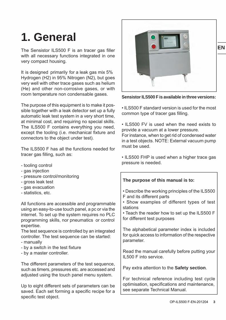
1. GeneralThe Sensistor ILS500 F is an tracer gas filler with all necessary functions integrated in one very compact housing.
It is designed primarily for a leak gas mix 5% Hydrogen (H2) in 95% Nitrogen (N2), but goes very well with other trace gases such as helium (He) and other non-corrosive gases, or with room temperature non condensable gases.
The purpose of this equipment is to make it pos-sible together with a leak detector set up a fully automatic leak test system in a very short time, at minimal cost, and requiring no special skills. The ILS500 F contains everything you need, except the tooling (i.e. mechanical fixture and connectors to the object under test).
The ILS500 F has all the functions needed for tracer gas filling, such as:
- tooling control - gas injection - pressure control/monitoring - gross leak test - gas evacuation - statistics, etc.
All functions are accessible and programmable using an easy-to-use touch panel, a pc or via the internet. To set up the system requires no PLC programming skills, nor pneumatics or control expertise.The test sequence is controlled by an integrated controller. The test sequence can be started:- manually- by a switch in the test fixture- by a master controller.
The different parameters of the test sequence, such as timers, pressures etc. are accessed and adjusted using the touch panel menu system.
Up to eight different sets of parameters can be saved. Each set forming a specific recipe for a specific test object.
The purpose of this manual is to:
• Describe the working principles of the ILS500 F and its different parts• Show examples of different types of test stations• Teach the reader how to set up the ILS500 F for different test purposes
The alphabetical parameter index is included for quick access to information of the respective parameter.
Read the manual carefully before putting your IL500 F into service.
Pay extra attention to the Safety section.
For technical reference including test cycle optimisation, specifications and maintenance, see separate Technical Manual.
Sensistor ILS500 F is available in three versions:
• ILS500 F standard version is used for the most common type of tracer gas filling.
• ILS500 FV is used when the need exists to provide a vacuum at a lower pressure. For instance, when to get rid of condensed water in a test objects. NOTE: External vacuum pump must be used.
• ILS500 FHP is used when a higher trace gas pressure is needed.
EN
4 OP-ILS500 F-EN-201204
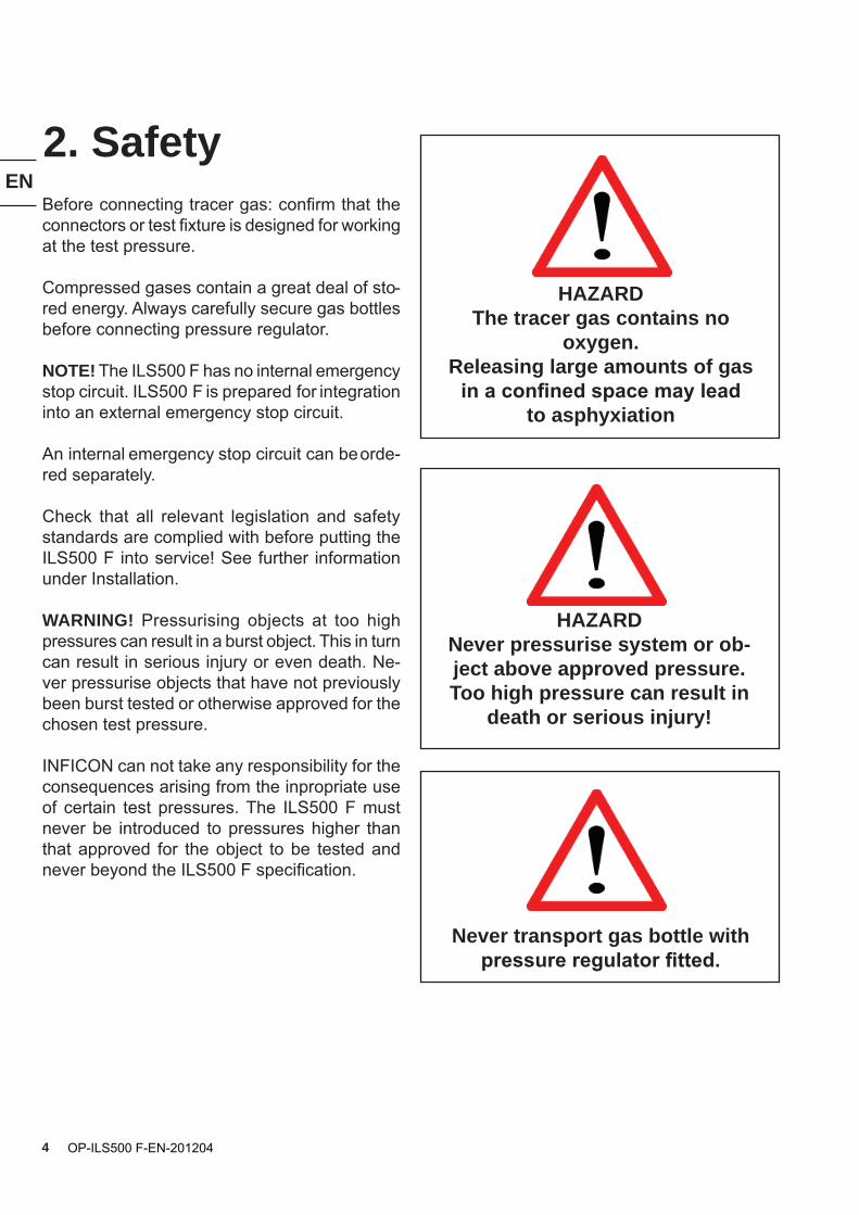
Before connecting tracer gas: confirm that the connectors or test fixture is designed for working at the test pressure.
Compressed gases contain a great deal of sto-red energy. Always carefully secure gas bottles before connecting pressure regulator.
NOTE! The ILS500 F has no internal emergency stop circuit. ILS500 F is prepared for integration into an external emergency stop circuit.
An internal emergency stop circuit can be orde-red separately.
Check that all relevant legislation and safety standards are complied with before putting the ILS500 F into service! See further information under Installation.
WARNING! Pressurising objects at too high pressures can result in a burst object. This in turn can result in serious injury or even death. Ne-ver pressurise objects that have not previously been burst tested or otherwise approved for the chosen test pressure.
INFICON can not take any responsibility for the consequences arising from the inpropriate use of certain test pressures. The ILS500 F must never be introduced to pressures higher than that approved for the object to be tested and never beyond the ILS500 F specification.
2. Safety
HAZARDThe tracer gas contains no
oxygen.Releasing large amounts of gas
in a confined space may lead to asphyxiation
HAZARDNever pressurise system or ob-ject above approved pressure. Too high pressure can result in
death or serious injury!
Never transport gas bottle with pressure regulator fitted.
EN
5OP-ILS500 F-EN-201204
3. Contents of deliveryWhen receiving the equipment, check that it has not been damaged during transport. Check that all the following items are included:
• ILS500 F
• Power Cable
• Screw Terminal Connectors for external I/O signals (total of 6)
• Thread Converter Set (ISO to NPT conversion)
• Hose Connection Kit
• Operating Instruction ILS500 F (this manual)
• CD with Technical Manual and other relevant manuals.
EN
6 OP-ILS500 F-EN-201204
4. Technical Description
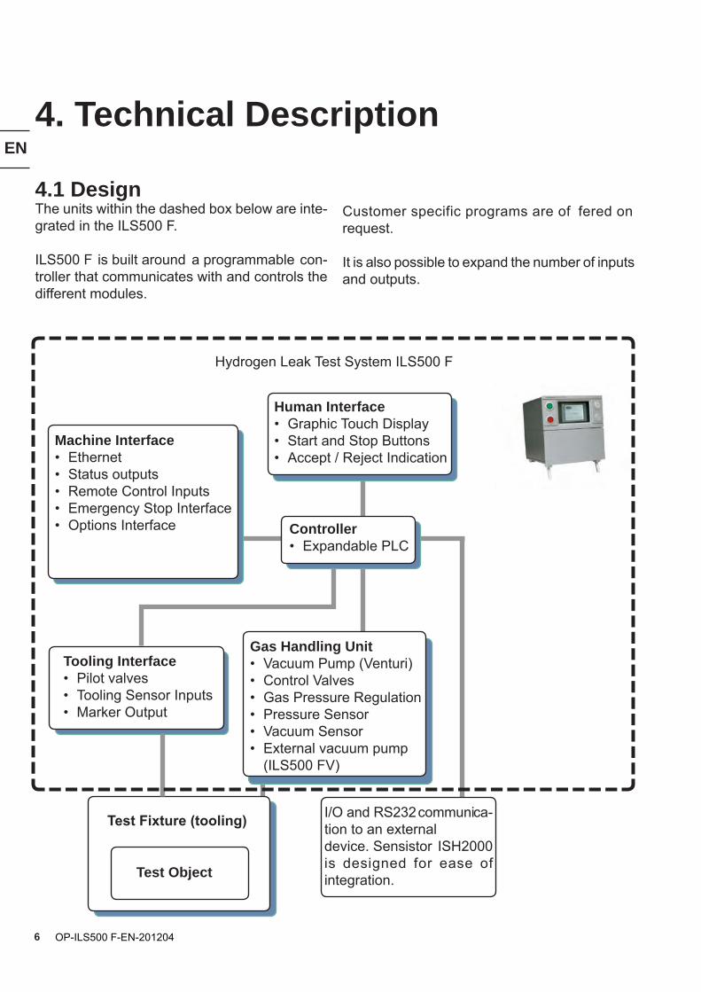
Tooling Interface• Pilot valves• Tooling Sensor Inputs• Marker Output
Gas Handling Unit• Vacuum Pump (Venturi)• Control Valves• Gas Pressure Regulation• Pressure Sensor• Vacuum Sensor• External vacuum pump (ILS500 FV)
Machine Interface• Ethernet• Status outputs• Remote Control Inputs• Emergency Stop Interface• Options Interface
Human Interface• Graphic Touch Display• Start and Stop Buttons• Accept / Reject Indication
I/O and RS232 communica-tion to an external device. Sensistor ISH2000 is designed for ease of integration.
Controller• Expandable PLC
Test Fixture (tooling)
Test Object
Hydrogen Leak Test System ILS500 F
Customer specific programs are of fered on request.
It is also possible to expand the number of inputs and outputs.
4.1 DesignThe units within the dashed box below are inte-grated in the ILS500 F.
ILS500 F is built around a programmable con-troller that communicates with and controls the different modules.
EN
7OP-ILS500 F-EN-201204
4.2. Test CycleThe following list shows the individual main steps of a complete test sequence.
Several of the steps are optional and can be turned off as explained in Section 7.3.
1. Standby. ILS500 F is idle waiting for Start signal.
2. Tooling Connection. Four air valves and four proximity switch inputs can be easily set up to control moderate test fixtures. Controller can be expanded for more demanding fixtures.
3. Pre Evacuation and Evacuation Test. The air is evacuated from the test object and a first gross leak test is made simultaneously. Evacua-tion is often necessary to ensure that the tracer gas reaches all parts of the tested object.
4. Vacuum Decay Test. Optional medium sen-sitivity leak test. Can be used to reveal leaks before filling with gas. This minimises spillage from gross leaks.
5. Gas Filling. Tracer gas filling before gas test.
6. Blockage Test. Reveals internal blockages in tested object. Practical for testing e.g. capil-laries etc.
7. Pressure Decay Test. Optional medium sen-sitivity leak test performed in parallel with tracer gas test. This test can for example be used for integral testing in parallel with a more sensitive gas test at selected points. Such differential testing is very cost effective, when applicable.
8. Leak detection with a leak detection instru-ment.
9. After Evacuation. Evacuation of tracer gas for minimised spillage. This can also include a very efficient air purge.
10.Tooling Disconnection. Disconnection of test fixture.
EN
8 OP-ILS500 F-EN-201204
5. InstallationFor a trouble free installation and operation of the ILS500 F we strongly recommend that you read through the entire Installation section.
Minor things that you do not consider important can make a big difference.
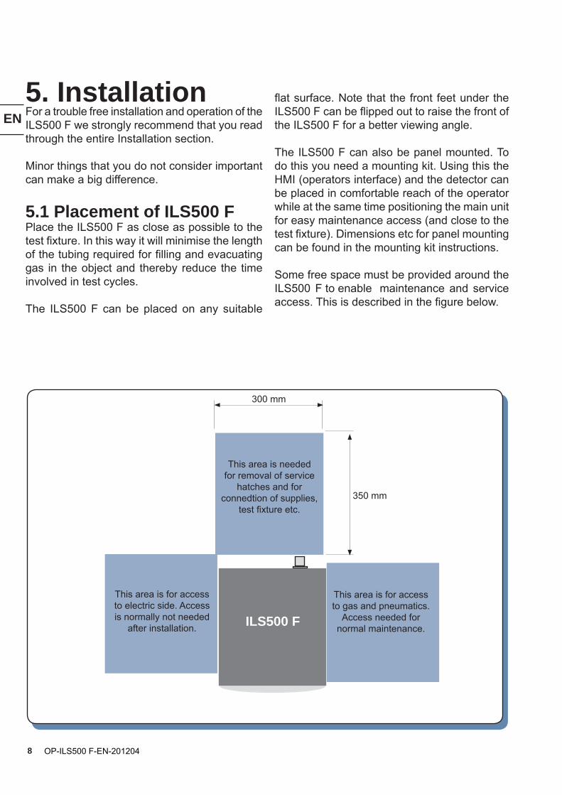
5.1 Placement of ILS500 FPlace the ILS500 F as close as possible to the test fixture. In this way it will minimise the length of the tubing required for filling and evacuating gas in the object and thereby reduce the time involved in test cycles.
The ILS500 F can be placed on any suitable
flat surface. Note that the front feet under the ILS500 F can be flipped out to raise the front of the ILS500 F for a better viewing angle.
The ILS500 F can also be panel mounted. To do this you need a mounting kit. Using this the HMI (operators interface) and the detector can be placed in comfortable reach of the operator while at the same time positioning the main unit for easy maintenance access (and close to the test fixture). Dimensions etc for panel mounting can be found in the mounting kit instructions.
Some free space must be provided around the ILS500 F to enable maintenance and service access. This is described in the figure below.
300 mm
350 mm
This area is needed for removal of service
hatches and for connedtion of supplies,
test fixture etc.
This area is for access to electric side. Access is normally not needed
after installation.
This area is for access to gas and pneumatics.
Access needed for normal maintenance.ILS500 F
EN
9OP-ILS500 F-EN-201204
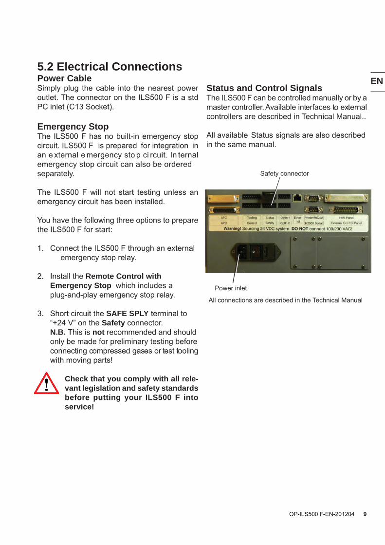
5.2 Electrical ConnectionsPower CableSimply plug the cable into the nearest power outlet. The connector on the ILS500 F is a std PC inlet (C13 Socket).
Emergency StopThe ILS500 F has no built-in emergency stop circuit. ILS500 F is prepared for integration in an e xternal e mergency sto p ci rcuit. In ternal emergency stop circuit can also be ordered separately.
The ILS500 F will not start testing unless an emergency circuit has been installed.
You have the following three options to prepare the ILS500 F for start:
1. Connect the ILS500 F through an external emergency stop relay.
2. Install the Remote Control with Emergency Stop which includes a plug-and-play emergency stop relay.
3. Short circuit the SAFE SPLY terminal to “+24 V” on the Safety connector. N.B. This is not recommended and should only be made for preliminary testing before connecting compressed gases or test tooling with moving parts!
Check that you comply with all rele-vant legislation and safety standards before putting your ILS500 F into service!
Status and Control SignalsThe ILS500 F can be controlled manually or by a master controller. Available interfaces to external controllers are described in Technical Manual..
All available Status signals are also described in the same manual.
Power inlet
Safety connector
All connections are described in the Technical Manual
EN
10 OP-ILS500 F-EN-201204
Type
Compressed Air
Tracer gas
Exhaust
Test Object
(Test Port 1
Test Port 2)
Specification
Pressure range*: 0.35 – 0,7 MPa (50 – 100 psi)(Decreased vacuum capaity below 0.5 MPa (70 psi)
Oil free and filtered to 5 µm.Dew point: Max 10°C (50°F) *HP models: 0.5 – 0.7 MPa (70 - 100 psi)Any tracer gas that is non corrosive or condense at test.Pressure*: F models: 0.005 – 1.0 MPa (0.72 – 145 psi)HP models: 0.02 – 4.5 MPa (3 - 652 psi)
Warning! Refer to Safety section.
Connect to ventilation duct.
Min capacity in duct: 30 m3/h (1000 SCFH).
Use Test Port 1 and plug Test Port 2 for single port connection.
Port thread
BSP 3/8”
(ISO 228/1-G3/8)
NPT 3/8“ adaptor included
BSP 3/8”
(ISO 228/1-G3/8)
NPT 3/8“ adaptor included
Barb Fitting: ID 25 mm (1”)N.B.: Do not use smallertubing! Max length 10 m.
BSP 3/8”
(ISO 228/1-G3/8)
NPT 3/8“ adaptors included
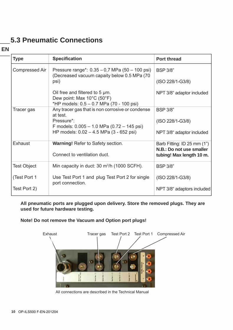
5.3 Pneumatic Connections
Exhaust Tracer gas Test Port 2 Test Port 1 Compressed Air
All pneumatic ports are plugged upon delivery. Store the removed plugs. They are used for future hardware testing.
Note! Do not remove the Vacuum and Option port plugs!
All connections are described in the Technical Manual
EN
11OP-ILS500 F-EN-201204
5.4 Compressed AirCompressed air is used to drive the Venturi pump, gas valves and the four tooling valves.
For reliable operation and minimised mainte -nance of the ILS500 F, it is essential that the compressed air is adequately filtered.
Make sure to install a 5 µm filter immediately ahead of the ILS500 F. Supply pressure is spe-cified to point after the filter position during peak consumption (see figure above). Using a low capacity filter will result in reduced evacuation and thereby longer test cycles.
5.5 Tracer Gas SupplyThe tracer gas is best ordered from your regular gas supplier.
Pressure of tracer gas should be: 0.005 – 1.0 MPa (0.72 – 145 psi). For HP model 0.02-4.5 MPa (3-352 psi).
Connecting the Tracer gas
1. Secure gas cylinder safely.
2. Open the cylinder valve briefly to blow out dirt that may have collected in the outlet.
3. Install gas regulator on cylinder. See further below for regulator recommendations.
4. Turn regulator fully counter clockwise for zero output pressure.
5. Connect a regular welding gas hose or similar between the Tracer gas port and the pressure regulator. Check that the hose is certified to withstand the maximum output pressure of the regulator.
6. Open cylinder valve and set regulator to desired pressure. See warning banner!
7. Open regulator outlet valve (if any).
ImportantMake sure that compressed air is
dry, well filtered and oil free!
Recommended filter grade is 5 µm or finer.
Inadequate filtering will result in in-creased maintenance.
HazardNever pressurise system or objects above approved pressure. Too high pressure can
result in death or serious injury!
5.6 Pressure RegulatorA simple, single stage regulator has pronounced input pressure dependence. The output pressure can increase considerably (double the set pres-sure or more), as the bottle pressure decreases.
The best way of avoiding this kind of problem is to buy a good two-stage regulator. They do not exhibit such pressure dependence.
EN
12 OP-ILS500 F-EN-201204
Inadequate exhaust installation is the most common reason for problems
with tracer gas leak testing.
Too narrow or too long exhaust line will result in reduced evacuation capacity and
thereby increased cycle time!
Important
Important
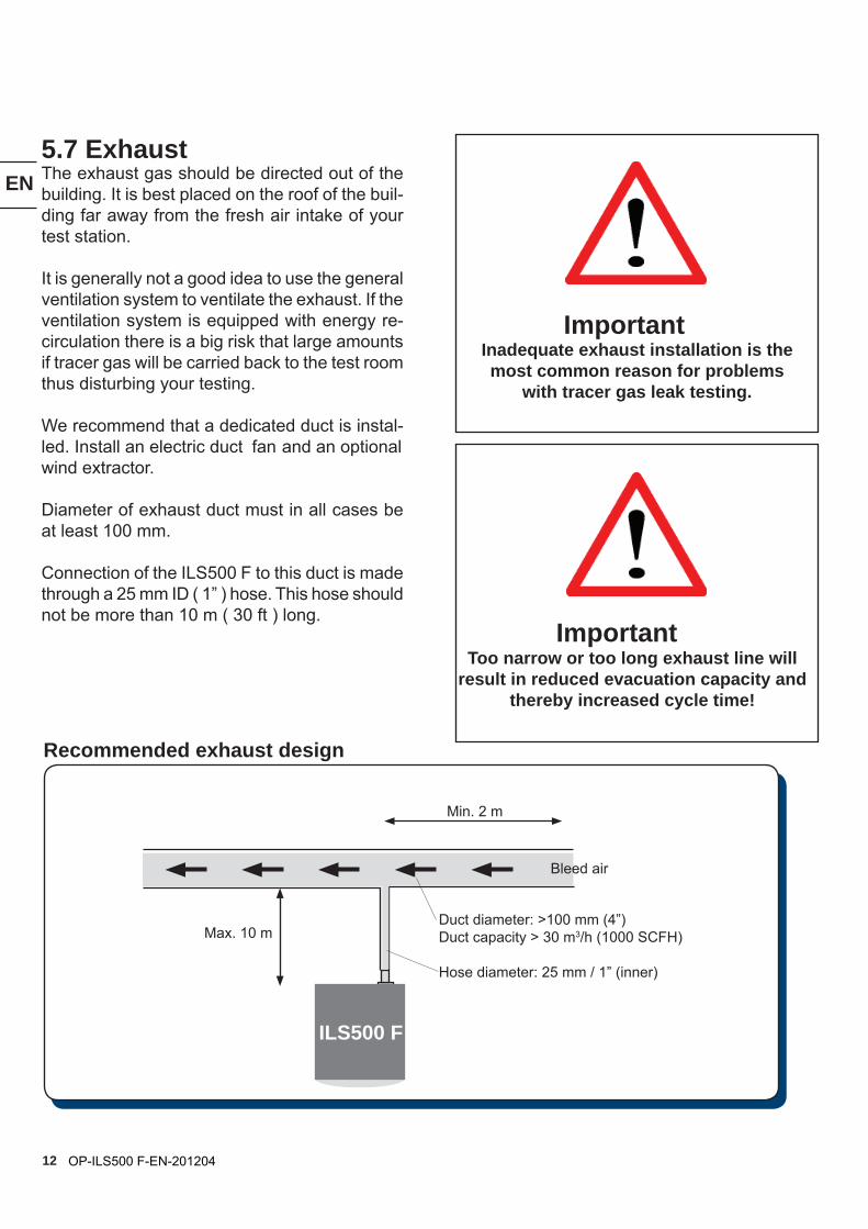
5.7 ExhaustThe exhaust gas should be directed out of the building. It is best placed on the roof of the buil-ding far away from the fresh air intake of your test station.
It is generally not a good idea to use the general ventilation system to ventilate the exhaust. If the ventilation system is equipped with energy re-circulation there is a big risk that large amounts if tracer gas will be carried back to the test room thus disturbing your testing.
We recommend that a dedicated duct is instal-led. Install an electric duct fan and an optional wind extractor.
Diameter of exhaust duct must in all cases be at least 100 mm.
Connection of the ILS500 F to this duct is made through a 25 mm ID ( 1” ) hose. This hose should not be more than 10 m ( 30 ft ) long.
Recommended exhaust design
Min. 2 m
Max. 10 mDuct diameter: >100 mm (4”)Duct capacity > 30 m3/h (1000 SCFH)
Hose diameter: 25 mm / 1” (inner)
Bleed air
ILS500 F
EN
13OP-ILS500 F-EN-201204
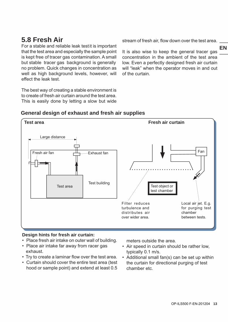
Design hints for fresh air curtain:• Place fresh air intake on outer wall of building.• Place air intake far away from racer gas exhaust.• Try to create a laminar flow over the test area.• Curtain should cover the entire test area (test hood or sample point) and extend at least 0.5
Test area Fresh air curtain
5.8 Fresh AirFor a stable and reliable leak test it is important that the test area and especially the sample point is kept free of tracer gas contamination. A small but stable tracer gas background is generally no problem. Quick changes in concentration as well as high background levels, however, will effect the leak test.
The best way of creating a stable environment is to create of fresh air curtain around the test area. This is easily done by letting a slow but wide
stream of fresh air, flow down over the test area.
It is also wise to keep the general tracer gas concentration in the ambient of the test area low. Even a perfectly designed fresh air curtain will “leak” when the operator moves in and out of the curtain.
Filter reduces turbulence and distr ibutes air over wider area.
Exhaust fan
Test buildingTest area
Fresh air fan
Large distance
Test object or test chamber
Local air jet. E.g. for purging test chamberbetween tests.
Fan
General design of exhaust and fresh air supplies
meters outside the area.• Air speed in curtain should be rather low, typically 0.1 m/s.• Additional small fan(s) can be set up within the curtain for directional purging of test chamber etc.
EN
14 OP-ILS500 F-EN-201204
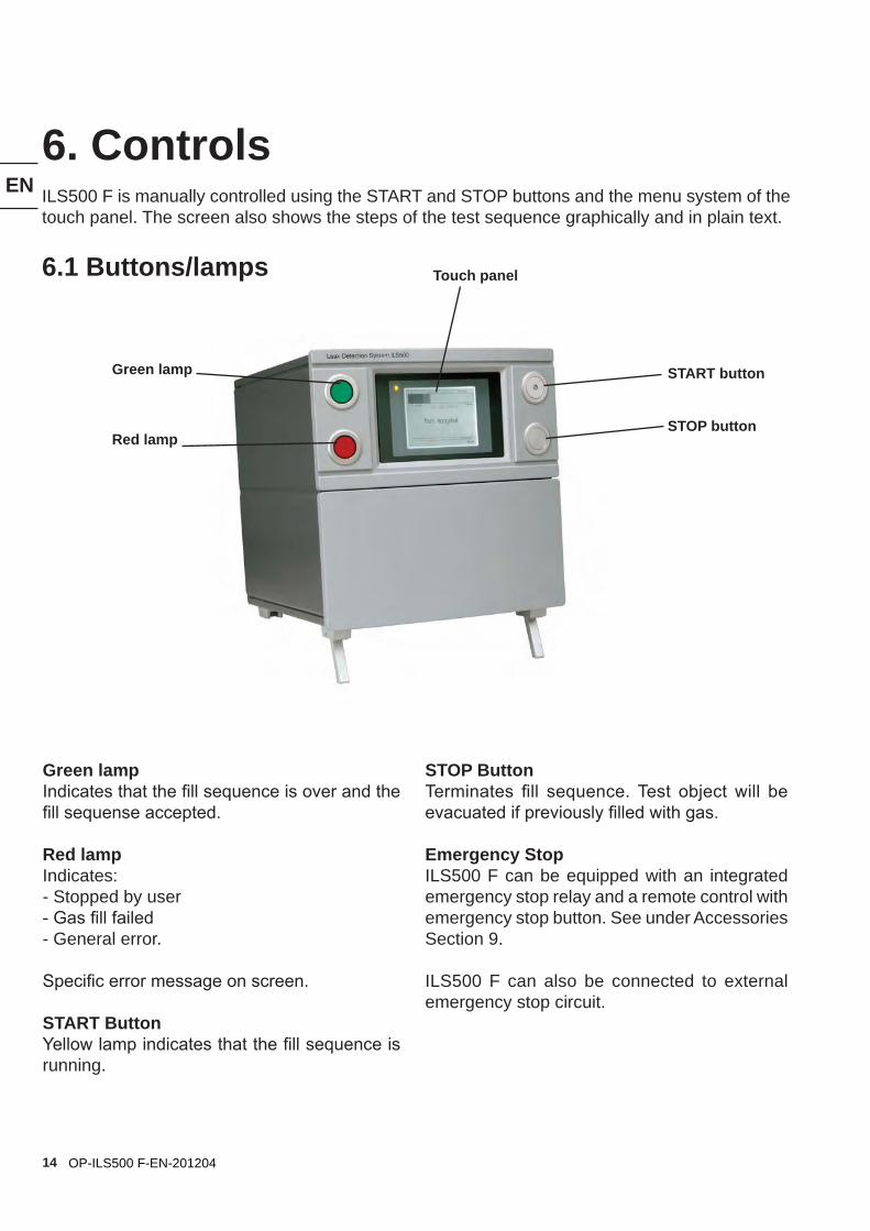
6. ControlsILS500 F is manually controlled using the START and STOP buttons and the menu system of the touch panel. The screen also shows the steps of the test sequence graphically and in plain text.
6.1 Buttons/lamps
Green lamp
Red lamp
Green lampIndicates that the fill sequence is over and the fill sequense accepted.
Red lampIndicates:- Stopped by user- Gas fill failed- General error.
Specific error message on screen.
START Button Yellow lamp indicates that the fill sequence is running.
START button
STOP button
Touch panel
STOP ButtonTerminates fill sequence. Test object will be evacuated if previously filled with gas.
Emergency StopILS500 F can be equipped with an integrated emergency stop relay and a remote control with emergency stop button. See under Accessories Section 9.
ILS500 F can also be connected to external emergency stop circuit.
EN
15OP-ILS500 F-EN-201204
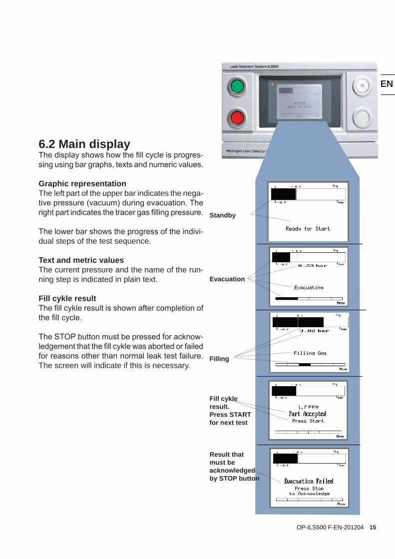
Standby
Evacuation
Filling
Fill cykle result.Press START for next test
Result that must be acknowledged by STOP button
6.2 Main displayThe display shows how the fill cycle is progres-sing using bar graphs, texts and numeric values.
Graphic representationThe left part of the upper bar indicates the nega-tive pressure (vacuum) during evacuation. The right part indicates the tracer gas filling pressure.
The lower bar shows the progress of the indivi-dual steps of the test sequence.
Text and metric valuesThe current pressure and the name of the run-ning step is indicated in plain text.
Fill cykle resultThe fill cykle result is shown after completion of the fill cycle.
The STOP button must be pressed for acknow-ledgement that the fill cykle was aborted or failed for reasons other than normal leak test failure. The screen will indicate if this is necessary.
EN
16 OP-ILS500 F-EN-201204
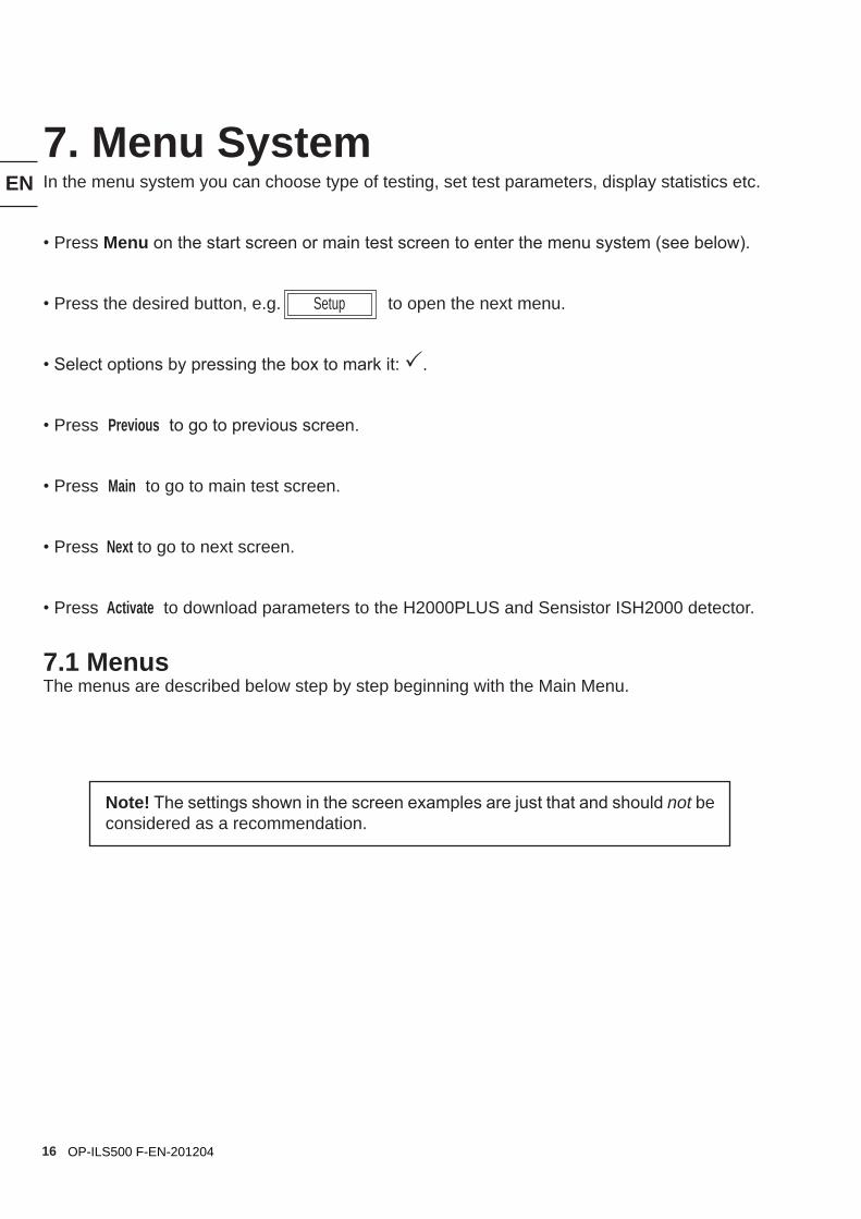
7. Menu SystemIn the menu system you can choose type of testing, set test parameters, display statistics etc.
• Press Menu on the start screen or main test screen to enter the menu system (see below).
• Press the desired button, e.g. Setup to open the next menu.
• Select options by pressing the box to mark it: P.
• Press Previous to go to previous screen.
• Press Main to go to main test screen.
• Press Next to go to next screen.
• Press Activate to download parameters to the H2000PLUS and Sensistor ISH2000 detector.
7.1 MenusThe menus are described below step by step beginning with the Main Menu.
Note! The settings shown in the screen examples are just that and should not be considered as a recommendation.
EN
17OP-ILS500 F-EN-201204
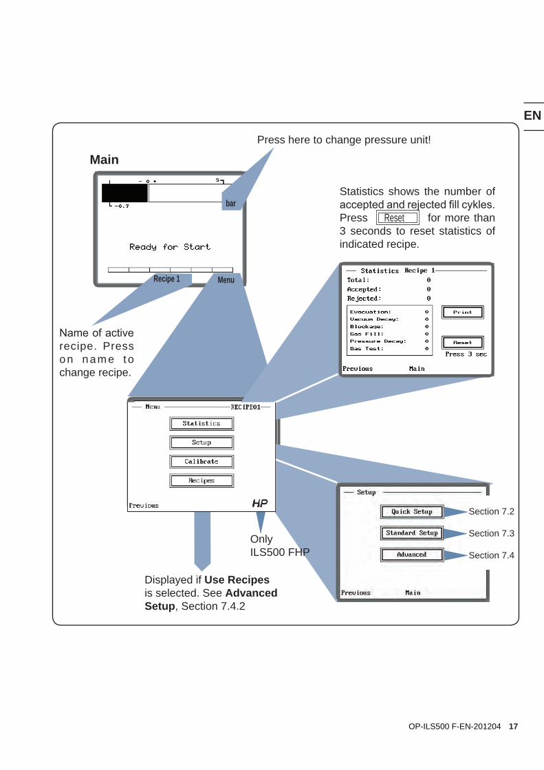
Main
Displayed if Use Recipes is selected. See Advanced Setup, Section 7.4.2
bar
Press here to change pressure unit!
Recipe 1
Name of active recipe. Press on name to change recipe.
Menu
Section 7.2
Section 7.3
Section 7.4
OnlyILS500 FHP
Statistics shows the number of accepted and rejected fill cykles. Press Reset for more than 3 seconds to reset statistics of indicated recipe.
EN
18 OP-ILS500 F-EN-201204
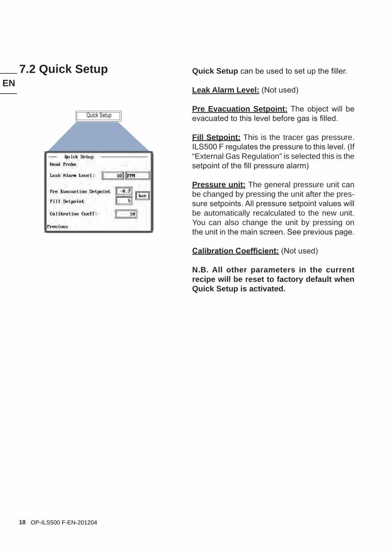
Quick Setup can be used to set up the filler.
Leak Alarm Level: (Not used)
Pre Evacuation Setpoint: The object will be evacuated to this level before gas is filled.
Fill Setpoint: This is the tracer gas pressure. ILS500 F regulates the pressure to this level. (If “External Gas Regulation” is selected this is the setpoint of the fill pressure alarm)
Pressure unit: The general pressure unit can be changed by pressing the unit after the pres-sure setpoints. All pressure setpoint values will be automatically recalculated to the new unit. You can also change the unit by pressing on the unit in the main screen. See previous page.
Calibration Coefficient: (Not used)
N.B. All other parameters in the current recipe will be reset to factory default when Quick Setup is activated.
7.2 Quick Setup
Quick Setup
EN
19OP-ILS500 F-EN-201204
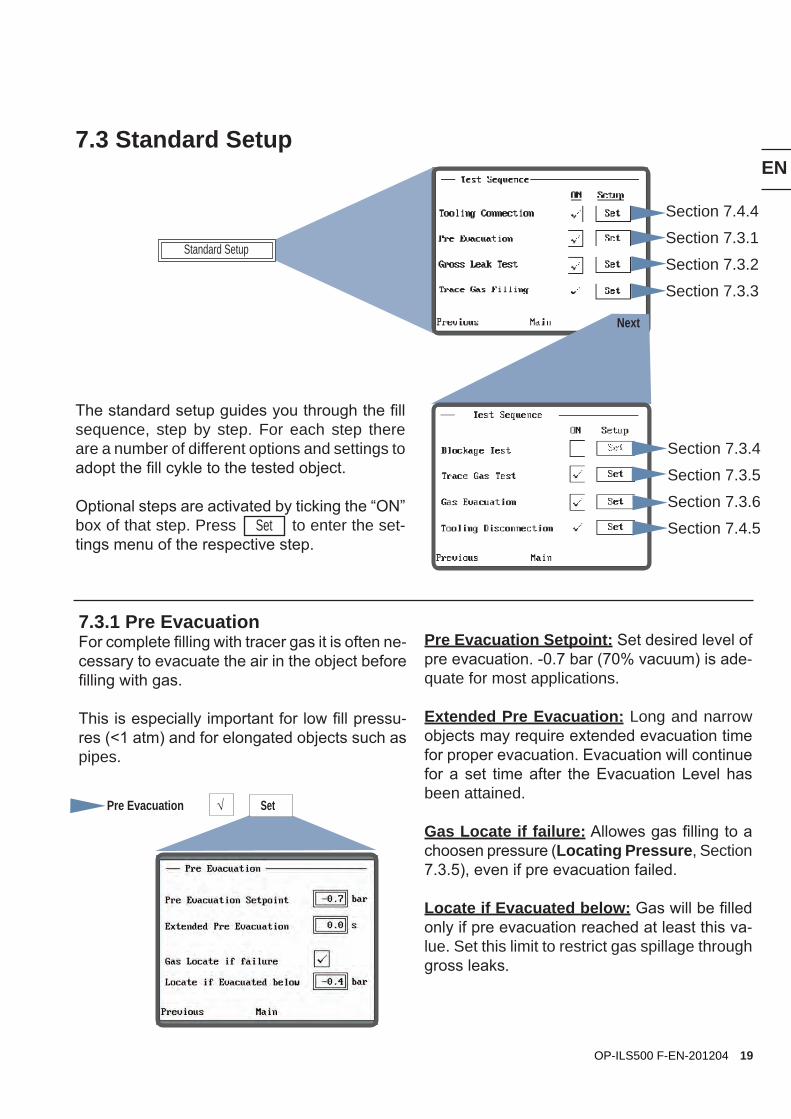
7.3 Standard Setup
The standard setup guides you through the fill sequence, step by step. For each step there are a number of different options and settings to adopt the fill cykle to the tested object.
Optional steps are activated by ticking the “ON” box of that step. Press Set to enter the set-tings menu of the respective step.
Section 7.4.4
Section 7.3.1
Section 7.3.2
Section 7.3.3
7.3.1 Pre EvacuationFor complete filling with tracer gas it is often ne-cessary to evacuate the air in the object before filling with gas.
This is especially important for low fill pressu-res (<1 atm) and for elongated objects such as pipes.
Pre Evacuation Setpoint: Set desired level of pre evacuation. -0.7 bar (70% vacuum) is ade-quate for most applications.
Extended Pre Evacuation: Long and narrow objects may require extended evacuation time for proper evacuation. Evacuation will continue for a set time after the Evacuation Level has been attained.
Gas Locate if failure: Allowes gas filling to a choosen pressure (Locating Pressure, Section 7.3.5), even if pre evacuation failed.
Locate if Evacuated below: Gas will be filled only if pre evacuation reached at least this va-lue. Set this limit to restrict gas spillage through gross leaks.
Pre Evacuation √ Set
Standard Setup
Section 7.3.4
Section 7.3.5
Section 7.3.6
Section 7.4.5
Next
EN
20 OP-ILS500 F-EN-201204
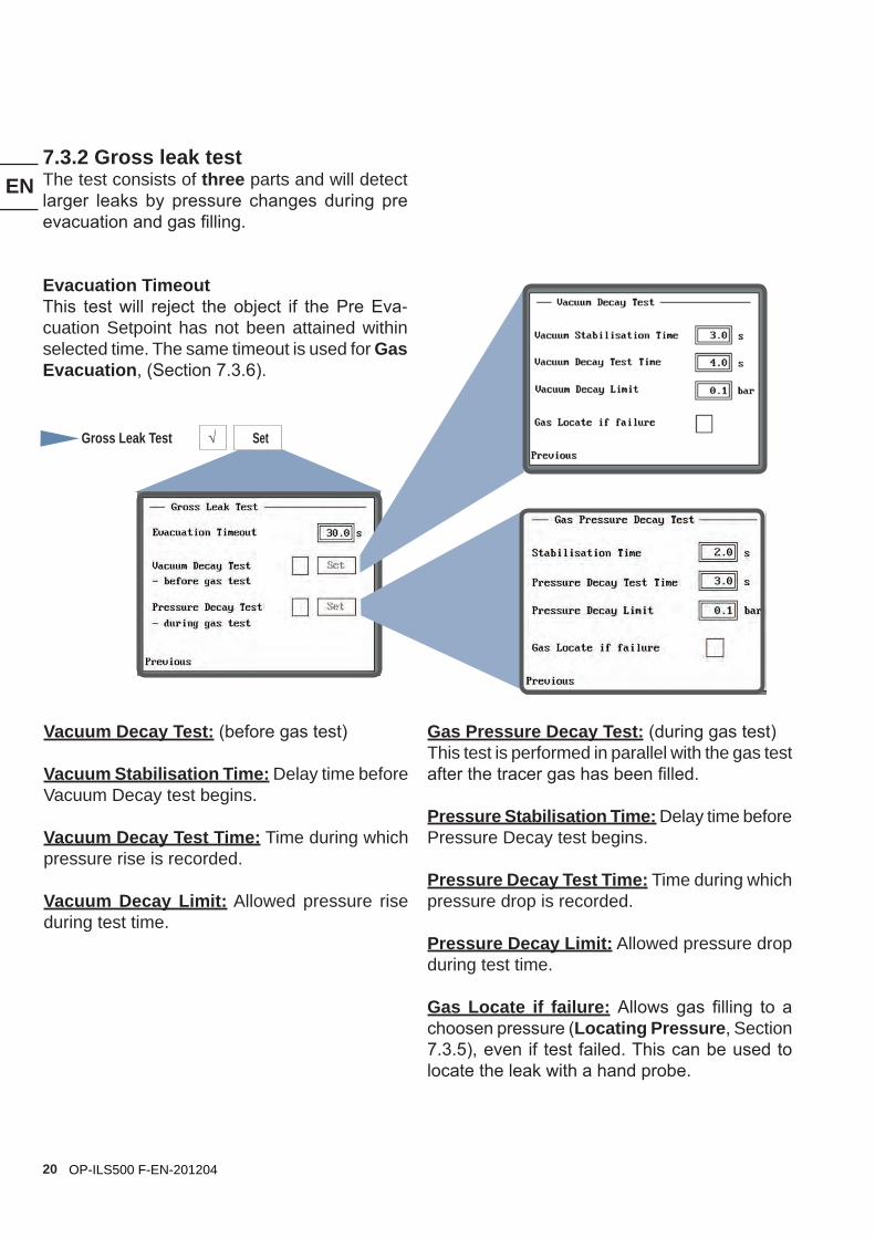
7.3.2 Gross leak testThe test consists of three parts and will detect larger leaks by pressure changes during pre evacuation and gas filling.
Evacuation Timeout This test will reject the object if the Pre Eva-cuation Setpoint has not been attained within selected time. The same timeout is used for Gas Evacuation, (Section 7.3.6).
Gross Leak Test √ Set
Vacuum Decay Test: (before gas test)
Vacuum Stabilisation Time: Delay time before Vacuum Decay test begins.
Vacuum Decay Test Time: Time during which pressure rise is recorded.
Vacuum Decay Limit: Allowed pressure rise during test time.
Gas Pressure Decay Test: (during gas test)This test is performed in parallel with the gas test after the tracer gas has been filled.
Pressure Stabilisation Time: Delay time before Pressure Decay test begins.
Pressure Decay Test Time: Time during which pressure drop is recorded.
Pressure Decay Limit: Allowed pressure drop during test time.
Gas Locate if failure: Allows gas filling to a choosen pressure (Locating Pressure, Section 7.3.5), even if test failed. This can be used to locate the leak with a hand probe.
EN
21OP-ILS500 F-EN-201204
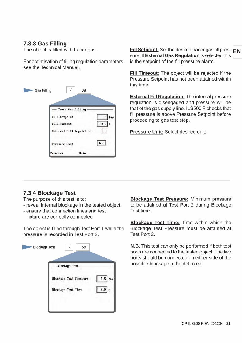
7.3.3 Gas FillingThe object is filled with tracer gas.
For optimisation of filling regulation parameters see the Technical Manual.
Fill Setpoint: Set the desired tracer gas fill pres-sure. If External Gas Regulation is selected this is the setpoint of the fill pressure alarm.
Fill Timeout: The object will be rejected if the Pressure Setpoint has not been attained within this time.
External Fill Regulation: The internal pressure regulation is disengaged and pressure will be that of the gas supply line. ILS500 F checks that fill pressure is above Pressure Setpoint before proceeding to gas test step.
Pressure Unit: Select desired unit.
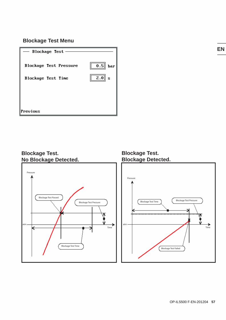
7.3.4 Blockage TestThe purpose of this test is to:- reveal internal blockage in the tested object,- ensure that connection lines and test fixture are correctly connected
The object is filled through Test Port 1 while the pressure is recorded in Test Port 2.
Blockage Test Pressure: Minimum pressure to be attained at Test Port 2 during Blockage Test time.
Blockage Test Time: Time within which the Blockage Test Pressure must be attained at Test Port 2.
N.B. This test can only be performed if both test ports are connected to the tested object. The two ports should be connected on either side of the possible blockage to be detected.
Gas Filling √ Set
Blockage Test √ Set
EN
22 OP-ILS500 F-EN-201204
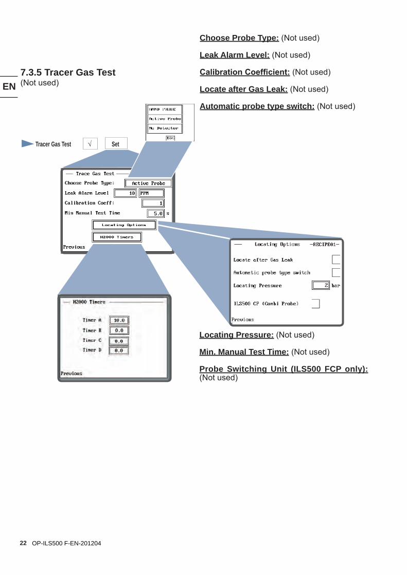
7.3.5 Tracer Gas Test(Not used)
Choose Probe Type: (Not used) Leak Alarm Level: (Not used)
Calibration Coefficient: (Not used)
Locate after Gas Leak: (Not used)
Automatic probe type switch: (Not used)
Locating Pressure: (Not used)
Min. Manual Test Time: (Not used)
Probe Switching Unit (ILS500 FCP only): (Not used)
Tracer Gas Test √ Set
EN
23OP-ILS500 F-EN-201204
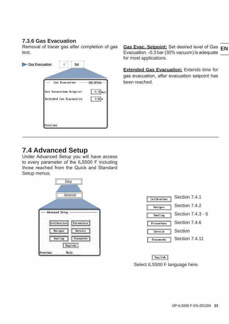
7.4 Advanced SetupUnder Advanced Setup you will have access to every parameter of the ILS500 F including those reached from the Quick and Standard Setup menus.
Section 7.4.1
Section 7.4.2
Section 7.4.3 - 5
Section 7.4.6
Section
Section 7.4.11
Select ILS500 F language here.
7.3.6 Gas EvacuationRemoval of tracer gas after completion of gas test.
Gas Evac. Setpoint: Set desired level of Gas Evacuation. -0.3 bar (30% vacuum) is adequate for most applications.
Extended Gas Evacuation: Extends time for gas evacuation, after evacuation setpoint has been reached.
Gas Evecuation √ Set
Advanced
Setup
EN
24 OP-ILS500 F-EN-201204
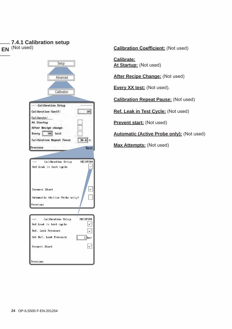
Calibration Coefficient: (Not used)
Calibrate:At Startup: (Not used)
After Recipe Change: (Not used)
Every XX test: (Not used).
Calibration Repeat Pause: (Not used)
Ref. Leak in Test Cycle: (Not used)
Prevent start: (Not used)
Automatic (Active Probe only): (Not used)
Max Attempts: (Not used)
7.4.1 Calibration setup(Not used)
Calibration
Advanced
Setup
Next
EN
25OP-ILS500 F-EN-201204
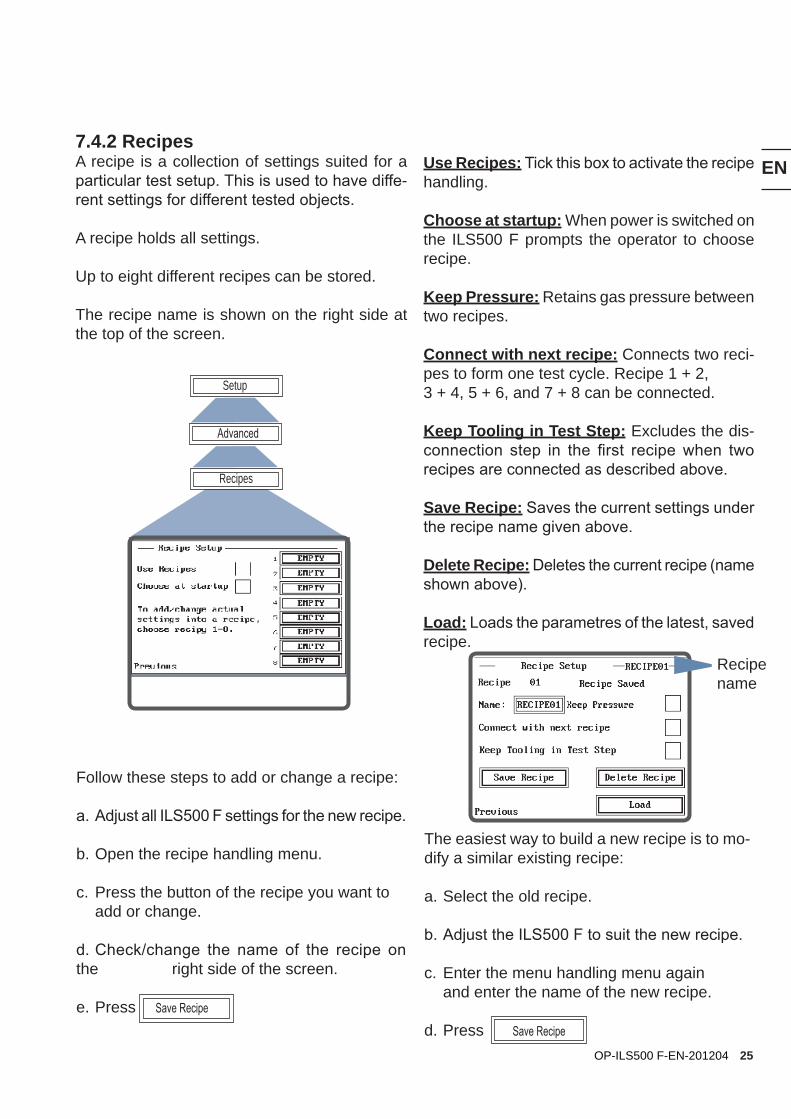
7.4.2 RecipesA recipe is a collection of settings suited for a particular test setup. This is used to have diffe-rent settings for different tested objects.
A recipe holds all settings.
Up to eight different recipes can be stored.
The recipe name is shown on the right side at the top of the screen.
Use Recipes: Tick this box to activate the recipe handling.
Choose at startup: When power is switched on the ILS500 F prompts the operator to choose recipe.
Keep Pressure: Retains gas pressure between two recipes.
Connect with next recipe: Connects two reci-pes to form one test cycle. Recipe 1 + 2, 3 + 4, 5 + 6, and 7 + 8 can be connected.
Keep Tooling in Test Step: Excludes the dis-connection step in the first recipe when two recipes are connected as described above.
Save Recipe: Saves the current settings under the recipe name given above.
Delete Recipe: Deletes the current recipe (name shown above).
Load: Loads the parametres of the latest, saved recipe.
Follow these steps to add or change a recipe:
a. Adjust all ILS500 F settings for the new recipe.
b. Open the recipe handling menu.
c. Press the button of the recipe you want to add or change.
d. Check/change the name of the recipe on the right side of the screen.
e. Press Save Recipe
The easiest way to build a new recipe is to mo-dify a similar existing recipe:
a. Select the old recipe.
b. Adjust the ILS500 F to suit the new recipe.
c. Enter the menu handling menu again and enter the name of the new recipe.
d. Press Save Recipe
Advanced
Setup
Recipes
Recipename
EN
26 OP-ILS500 F-EN-201204
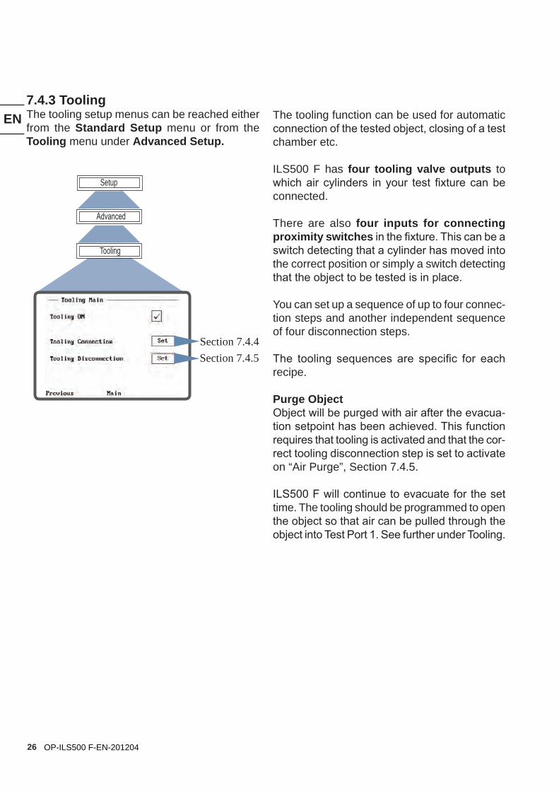
7.4.3 ToolingThe tooling setup menus can be reached either from the Standard Setup menu or from the Tooling menu under Advanced Setup.
The tooling function can be used for automatic connection of the tested object, closing of a test chamber etc.
ILS500 F has four tooling valve outputs to which air cylinders in your test fixture can be connected.
There are also four inputs for connecting proximity switches in the fixture. This can be a switch detecting that a cylinder has moved into the correct position or simply a switch detecting that the object to be tested is in place.
You can set up a sequence of up to four connec-tion steps and another independent sequence of four disconnection steps.
The tooling sequences are specific for each recipe.
Purge Object Object will be purged with air after the evacua-tion setpoint has been achieved. This function requires that tooling is activated and that the cor-rect tooling disconnection step is set to activate on “Air Purge”, Section 7.4.5.
ILS500 F will continue to evacuate for the set time. The tooling should be programmed to open the object so that air can be pulled through the object into Test Port 1. See further under Tooling.
Advanced
Setup
Tooling
Section 7.4.4Section 7.4.5
EN
27OP-ILS500 F-EN-201204
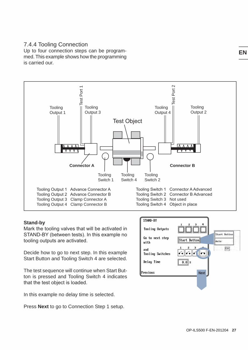
Connector A Connector B
Tooling Output 1
Tooling Output 2
Tooling Output 3
Tooling Output 4
Tooling Switch 1
Tooling Switch 2
Tooling Switch 4
Test
Por
t 1
Test
Por
t 2
Tooling Output 1 Advance Connector ATooling Output 2 Advance Connector BTooling Output 3 Clamp Connector ATooling Output 4 Clamp Connector B
Tooling Switch 1 Connector A AdvancedTooling Switch 2 Connector B AdvancedTooling Switch 3 Not usedTooling Switch 4 Object in place
Test Object
7.4.4 Tooling ConnectionUp to four connection steps can be program-med. This example shows how the programming is carried our.
Stand-by Mark the tooling valves that will be activated in STAND-BY (between tests). In this example no tooling outputs are activated.
Decide how to go to next step. In this example Start Button and Tooling Switch 4 are selected.
The test sequence will continue when Start But-ton is pressed and Tooling Switch 4 indicates that the test object is loaded.
In this example no delay time is selected.
Press Next to go to Connection Step 1 setup.
Next
EN
28 OP-ILS500 F-EN-201204
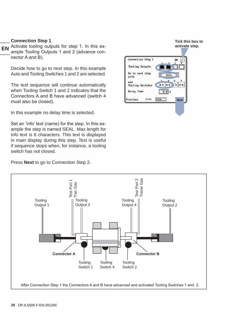
Connection Step 1Activate tooling outputs for step 1. In this ex-ample Tooling Outputs 1 and 2 (advance con-nector A and B).
Decide how to go to next step. In this example Auto and Tooling Switches 1 and 2 are selected.
The test sequence will continue automatically when Tooling Switch 1 and 2 indicates that the Connectors A and B have advanced (switch 4 must also be closed).
In this example no delay time is selected.
Set an ’info’ text (name) for the step. In this ex-ample the step is named SEAL. Max length for info text is 6 characters. This text is displayed in main display during this step. Text is useful if sequence stops when, for instance, a tooling switch has not closed. Press Next to go to Connection Step 2.
Connector A Connector B
Tooling Output 1
Tooling Output 2
Tooling Output 3
Tooling Output 4
Tooling Switch 1
Tooling Switch 2
Tooling Switch 4
After Connection Step 1 the Connectors A and B have advanced and activated Tooling Switches 1 and 2.
Tick this box to activate step.
Test
Por
t 1Tr
ac G
as
Test
Por
t 2Tr
acer
Gas
Next
EN
29OP-ILS500 F-EN-201204
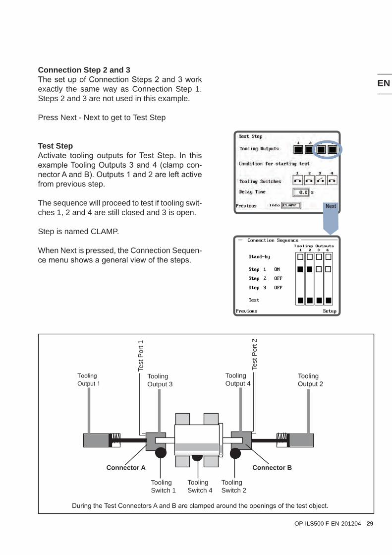
Connection Step 2 and 3The set up of Connection Steps 2 and 3 work exactly the same way as Connection Step 1. Steps 2 and 3 are not used in this example.
Press Next - Next to get to Test Step
Test StepActivate tooling outputs for Test Step. In this example Tooling Outputs 3 and 4 (clamp con-nector A and B). Outputs 1 and 2 are left active from previous step. The sequence will proceed to test if tooling swit-ches 1, 2 and 4 are still closed and 3 is open. Step is named CLAMP.
When Next is pressed, the Connection Sequen-ce menu shows a general view of the steps.
During the Test Connectors A and B are clamped around the openings of the test object.
Connector A Connector B
Tooling Output 1
Tooling Output 2
Tooling Output 3
Tooling Output 4
Tooling Switch 1
Tooling Switch 2
Tooling Switch 4
Test
Por
t 1
Test
Por
t 2
Next
EN
30 OP-ILS500 F-EN-201204
Connector A Connector B
Tooling Output 1
Tooling Output 2
Tooling Output 3
Tooling Output 4
Tooling Switch 1
Tooling Switch 2
Tooling Switch 4
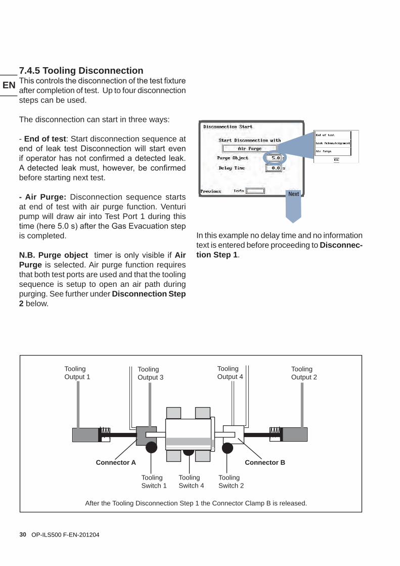
7.4.5 Tooling DisconnectionThis controls the disconnection of the test fixture after completion of test. Up to four disconnection steps can be used.
The disconnection can start in three ways:
- End of test: Start disconnection sequence at end of leak test Disconnection will start even if operator has not confirmed a detected leak. A detected leak must, however, be confirmed before starting next test.
- Air Purge: Disconnection sequence starts at end of test with air purge function. Venturi pump will draw air into Test Port 1 during this time (here 5.0 s) after the Gas Evacuation step is completed.
N.B. Purge object timer is only visible if Air Purge is selected. Air purge function requires that both test ports are used and that the tooling sequence is setup to open an air path during purging. See further under Disconnection Step 2 below.
After the Tooling Disconnection Step 1 the Connector Clamp B is released.
Next
In this example no delay time and no information text is entered before proceeding to Disconnec-tion Step 1.
EN
31OP-ILS500 F-EN-201204
Test
Por
t 1
Connector A Connector B
Tooling Output 1
Tooling Output 2
Tooling Output 3
Tooling Output 4
Tooling Switch 1
Tooling Switch 2
Tooling Switch 4
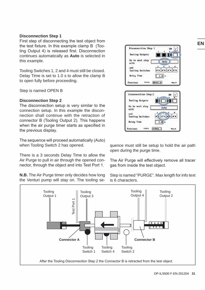
After the Tooling Disconnection Step 2 the Connector B is retracted from the test object.
Disconnection Step 1First step of disconnecting the test object from the test fixture. In this example clamp B (Too-ling Output 4) is released first. Disconnection continues automatically as Auto is selected in this example.
Tooling Switches 1, 2 and 4 must still be closed. Delay Time is set to 1.0 s to allow the clamp B to open fully before proceeding.
Step is named OPEN B
Disconnection Step 2The disconnection setup is very similar to the connection setup. In this example the discon-nection shall continue with the retraction of connector B (Tooling Output 2). This happens when the air purge timer starts as specified in the previous display.
The sequence will proceed automatically (Auto) when Tooling Switch 2 has opened.
There is a 3 seconds Delay Time to allow the Air Purge to pull in air through the opened con-nector, through the object and into Test Port 1.
N.B. The Air Purge timer only decides how long the Venturi pump will stay on. The tooling se-
quence must still be setup to hold the air path open during the purge time.
The Air Purge will effectively remove all tracer gas from inside the test object.
Step is named ”PURGE”. Max length for info text is 6 characters.
EN
32 OP-ILS500 F-EN-201204
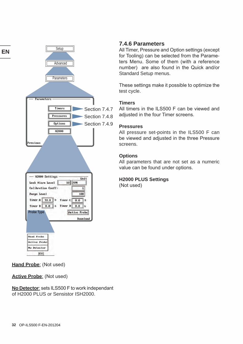
7.4.6 ParametersAll Timer, Pressure and Option settings (except for Tooling) can be selected from the Parame-ters Menu. Some of them (with a reference number) are also found in the Quick and/or Standard Setup menus.
These settings make it possible to optimize the test cycle.
TimersAll timers in the ILS500 F can be viewed and adjusted in the four Timer screens.
PressuresAll pressure set-points in the ILS500 F can be viewed and adjusted in the three Pressure screens.
OptionsAll parameters that are not set as a numeric value can be found under options.
H2000 PLUS Settings(Not used)
Parameters
Advanced
Setup
Hand Probe: (Not used)
Active Probe: (Not used)
No Detector: sets ILS500 F to work independant of H2000 PLUS or Sensistor ISH2000.
Section 7.4.7Section 7.4.8Section 7.4.9
Probe Type
EN
33OP-ILS500 F-EN-201204
Timers
Parameters
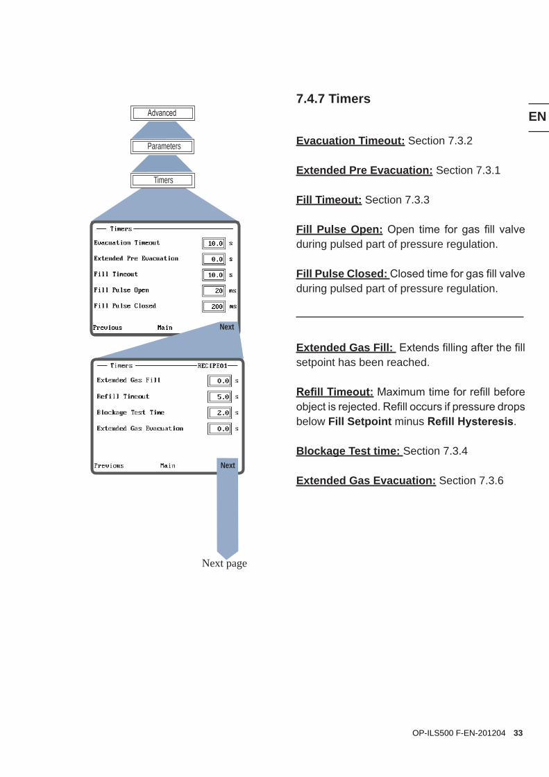
Advanced7.4.7 Timers
Evacuation Timeout: Section 7.3.2
Extended Pre Evacuation: Section 7.3.1
Fill Timeout: Section 7.3.3
Fill Pulse Open: Open time for gas fill valve during pulsed part of pressure regulation.
Fill Pulse Closed: Closed time for gas fill valve during pulsed part of pressure regulation.
Extended Gas Fill: Extends filling after the fill setpoint has been reached.
Refill Timeout: Maximum time for refill before object is rejected. Refill occurs if pressure drops below Fill Setpoint minus Refill Hysteresis.
Blockage Test time: Section 7.3.4
Extended Gas Evacuation: Section 7.3.6
Next
Next page
Next
EN
34 OP-ILS500 F-EN-201204
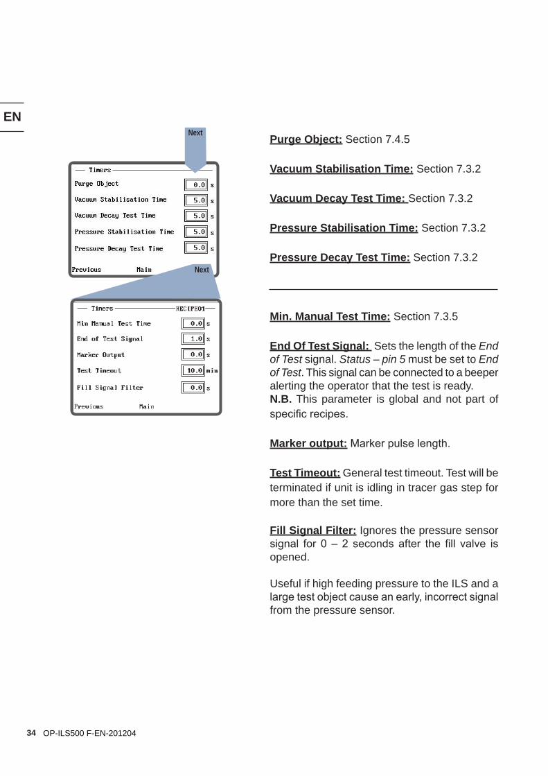
Purge Object: Section 7.4.5
Vacuum Stabilisation Time: Section 7.3.2
Vacuum Decay Test Time: Section 7.3.2
Pressure Stabilisation Time: Section 7.3.2
Pressure Decay Test Time: Section 7.3.2
Min. Manual Test Time: Section 7.3.5
End Of Test Signal: Sets the length of the End of Test signal. Status – pin 5 must be set to End of Test. This signal can be connected to a beeper alerting the operator that the test is ready.N.B. This parameter is global and not part of specific recipes.
Marker output: Marker pulse length.
Test Timeout: General test timeout. Test will be terminated if unit is idling in tracer gas step for more than the set time.
Fill Signal Filter: Ignores the pressure sensor signal for 0 – 2 seconds after the fill valve is opened.
Useful if high feeding pressure to the ILS and a large test object cause an early, incorrect signal from the pressure sensor.
Next
Next
EN
35OP-ILS500 F-EN-201204
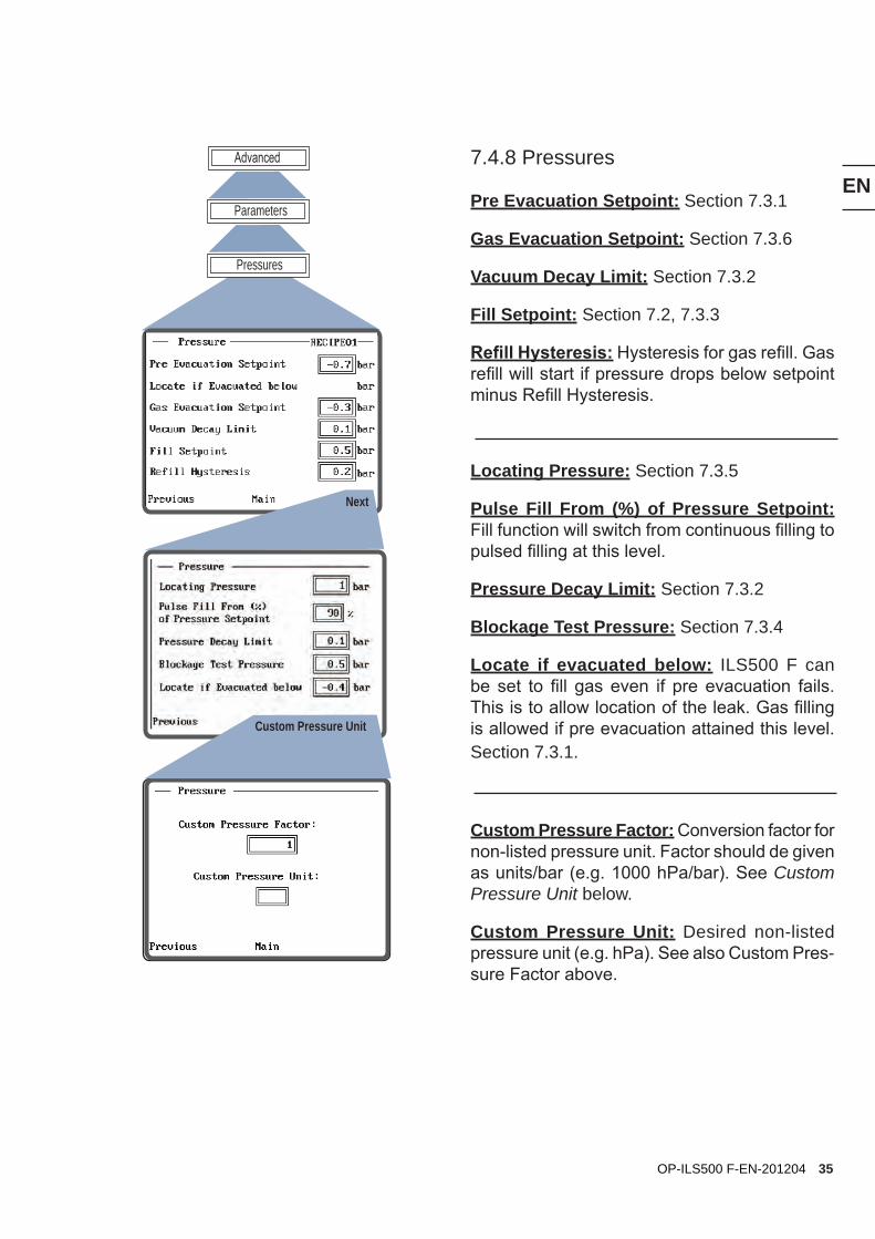
7.4.8 Pressures
Pre Evacuation Setpoint: Section 7.3.1
Gas Evacuation Setpoint: Section 7.3.6
Vacuum Decay Limit: Section 7.3.2
Fill Setpoint: Section 7.2, 7.3.3
Refill Hysteresis: Hysteresis for gas refill. Gas refill will start if pressure drops below setpoint minus Refill Hysteresis.
Locating Pressure: Section 7.3.5
Pulse Fill From (%) of Pressure Setpoint: Fill function will switch from continuous filling to pulsed filling at this level.
Pressure Decay Limit: Section 7.3.2
Blockage Test Pressure: Section 7.3.4
Locate if evacuated below: ILS500 F can be set to fill gas even if pre evacuation fails. This is to allow location of the leak. Gas filling is allowed if pre evacuation attained this level. Section 7.3.1.
Custom Pressure Factor: Conversion factor for non-listed pressure unit. Factor should de given as units/bar (e.g. 1000 hPa/bar). See Custom Pressure Unit below.
Custom Pressure Unit: Desired non-listed pressure unit (e.g. hPa). See also Custom Pres-sure Factor above.
Pressures
Parameters
Advanced
Next
Custom Pressure Unit
EN
36 OP-ILS500 F-EN-201204
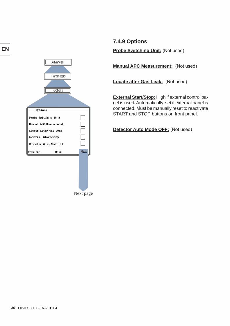
7.4.9 OptionsProbe Switching Unit: (Not used)
Manual APC Measurement: (Not used)
Locate after Gas Leak: (Not used)
External Start/Stop: High if external control pa-nel is used. Automatically set if external panel is connected. Must be manually reset to reactivate START and STOP buttons on front panel.
Detector Auto Mode OFF: (Not used)
Options
Parameters
Advanced
Next page
Next
EN
37OP-ILS500 F-EN-201204
Next page
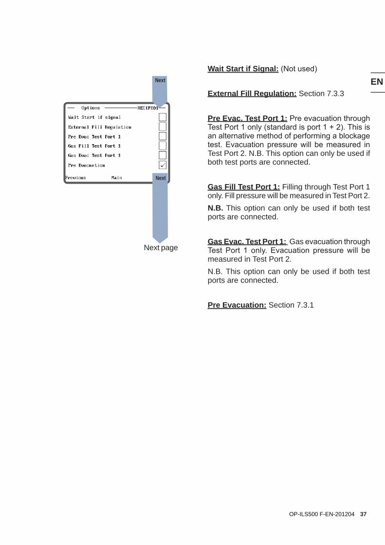
Wait Start if Signal: (Not used)
External Fill Regulation: Section 7.3.3
Pre Evac. Test Port 1: Pre evacuation through Test Port 1 only (standard is port 1 + 2). This is an alternative method of performing a blockage test. Evacuation pressure will be measured in Test Port 2. N.B. This option can only be used if both test ports are connected.
Gas Fill Test Port 1: Filling through Test Port 1 only. Fill pressure will be measured in Test Port 2.N.B. This option can only be used if both test ports are connected.
Gas Evac. Test Port 1: Gas evacuation through Test Port 1 only. Evacuation pressure will be measured in Test Port 2. N.B. This option can only be used if both test ports are connected.
Pre Evacuation: Section 7.3.1
Next
Next
EN
38 OP-ILS500 F-EN-201204
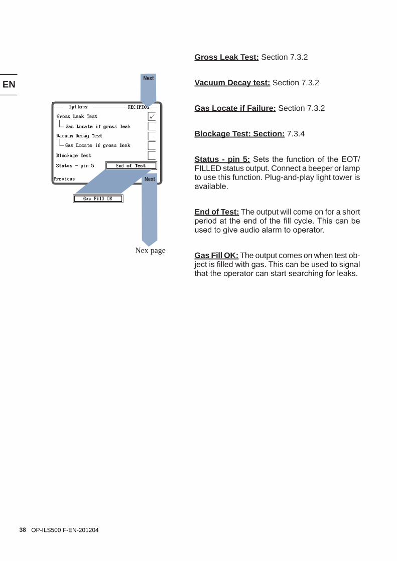
Gross Leak Test: Section 7.3.2
Vacuum Decay test: Section 7.3.2
Gas Locate if Failure: Section 7.3.2
Blockage Test: Section: 7.3.4
Status - pin 5: Sets the function of the EOT/FILLED status output. Connect a beeper or lamp to use this function. Plug-and-play light tower is available.
End of Test: The output will come on for a short period at the end of the fill cycle. This can be used to give audio alarm to operator.
Gas Fill OK: The output comes on when test ob-ject is filled with gas. This can be used to signal that the operator can start searching for leaks.
Nex page
Next
Next
EN
39OP-ILS500 F-EN-201204
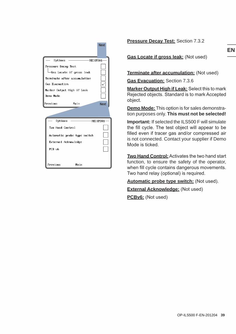
Pressure Decay Test: Section 7.3.2
Gas Locate if gross leak: (Not used)
Terminate after accumulation: (Not used)
Gas Evacuation: Section 7.3.6
Marker Output High if Leak: Select this to mark Rejected objects. Standard is to mark Accepted object.
Demo Mode: This option is for sales demonstra-tion purposes only. This must not be selected! Important: If selected the ILS500 F will simulate the fill cycle. The test object will appear to be filled even if tracer gas and/or compressed air is not connected. Contact your supplier if Demo Mode is ticked.
Two Hand Control: Activates the two hand start function, to ensure the safety of the operator, when fill cycle contains dangerous movements. Two hand relay (optional) is required.
Automatic probe type switch: (Not used).
External Acknowledge: (Not used)
PCBv6: (Not used)
Next
Next
EN
40 OP-ILS500 F-EN-201204
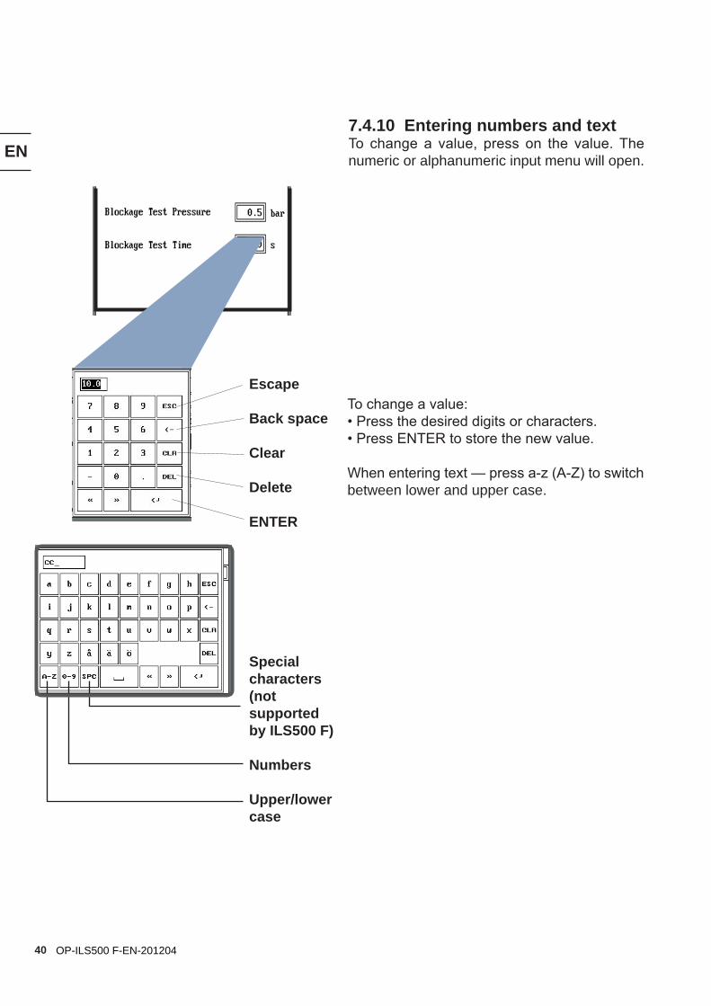
7.4.10 Entering numbers and textTo change a value, press on the value. The numeric or alphanumeric input menu will open.
Escape
Back space
Clear
Delete
ENTER
Special characters (not supported by ILS500 F)
Numbers
Upper/lower case
To change a value:• Press the desired digits or characters.• Press ENTER to store the new value.
When entering text — press a-z (A-Z) to switch between lower and upper case.
EN
41OP-ILS500 F-EN-201204
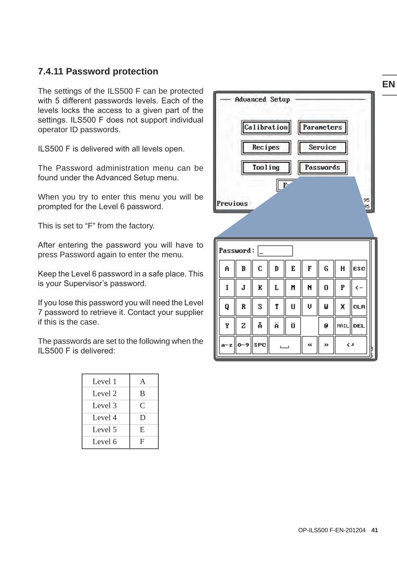
7.4.11 Password protection
The settings of the ILS500 F can be protected with 5 different passwords levels. Each of the levels locks the access to a given part of the settings. ILS500 F does not support individual operator ID passwords.
ILS500 F is delivered with all levels open.
The Password administration menu can be found under the Advanced Setup menu.
When you try to enter this menu you will be prompted for the Level 6 password.
This is set to “F” from the factory.
After entering the password you will have to press Password again to enter the menu.
Keep the Level 6 password in a safe place. This is your Supervisor’s password.
If you lose this password you will need the Level 7 password to retrieve it. Contact your supplier if this is the case.
The passwords are set to the following when the ILS500 F is delivered:
Level 1 ALevel 2 BLevel 3 CLevel 4 DLevel 5 ELevel 6 F
EN
42 OP-ILS500 F-EN-201204
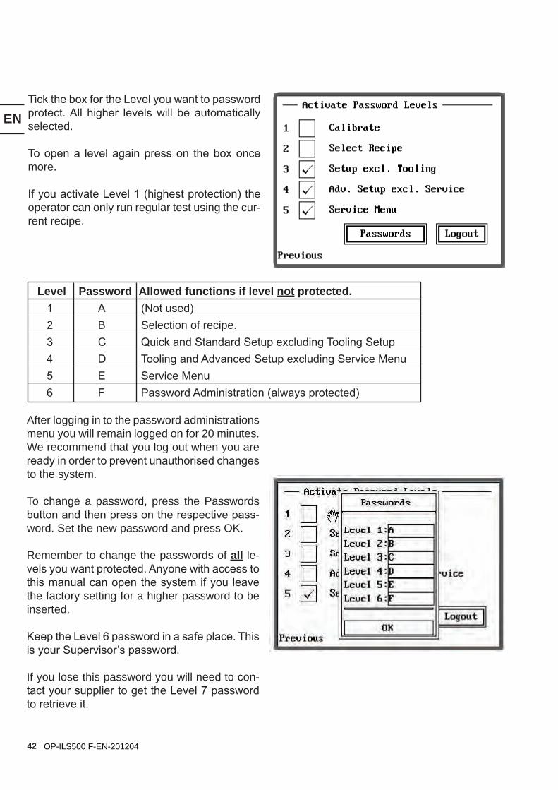
Tick the box for the Level you want to password protect. All higher levels will be automatically selected.
To open a level again press on the box once more.
If you activate Level 1 (highest protection) the operator can only run regular test using the cur-rent recipe.
After logging in to the password administrations menu you will remain logged on for 20 minutes. We recommend that you log out when you are ready in order to prevent unauthorised changes to the system.
To change a password, press the Passwords button and then press on the respective pass-word. Set the new password and press OK.
Remember to change the passwords of all le-vels you want protected. Anyone with access to this manual can open the system if you leave the factory setting for a higher password to be inserted.
Keep the Level 6 password in a safe place. This is your Supervisor’s password.
If you lose this password you will need to con-tact your supplier to get the Level 7 password to retrieve it.
Level Password Allowed functions if level not protected. 1 A (Not used) 2 B Selection of recipe. 3 C Quick and Standard Setup excluding Tooling Setup 4 D Tooling and Advanced Setup excluding Service Menu 5 E Service Menu 6 F Password Administration (always protected)
EN
43OP-ILS500 F-EN-201204
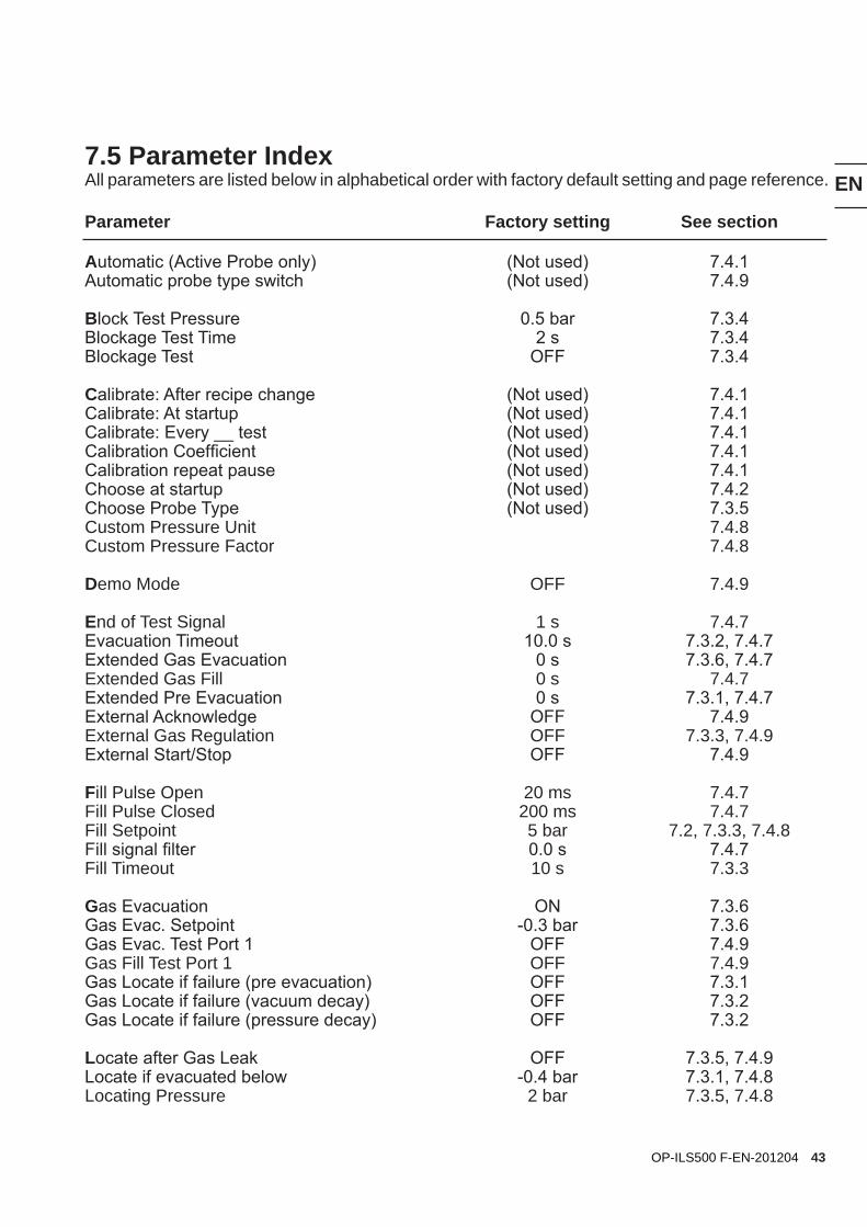
7.5 Parameter IndexAll parameters are listed below in alphabetical order with factory default setting and page reference.
Parameter Factory setting See section
Automatic (Active Probe only) (Not used) 7.4.1Automatic probe type switch (Not used) 7.4.9
Block Test Pressure 0.5 bar 7.3.4Blockage Test Time 2 s 7.3.4Blockage Test OFF 7.3.4
Calibrate: After recipe change (Not used) 7.4.1Calibrate: At startup (Not used) 7.4.1Calibrate: Every __ test (Not used) 7.4.1Calibration Coefficient (Not used) 7.4.1Calibration repeat pause (Not used) 7.4.1Choose at startup (Not used) 7.4.2Choose Probe Type (Not used) 7.3.5Custom Pressure Unit 7.4.8Custom Pressure Factor 7.4.8
Demo Mode OFF 7.4.9
End of Test Signal 1 s 7.4.7Evacuation Timeout 10.0 s 7.3.2, 7.4.7Extended Gas Evacuation 0 s 7.3.6, 7.4.7Extended Gas Fill 0 s 7.4.7Extended Pre Evacuation 0 s 7.3.1, 7.4.7External Acknowledge OFF 7.4.9External Gas Regulation OFF 7.3.3, 7.4.9External Start/Stop OFF 7.4.9
Fill Pulse Open 20 ms 7.4.7Fill Pulse Closed 200 ms 7.4.7Fill Setpoint 5 bar 7.2, 7.3.3, 7.4.8Fill signal filter 0.0 s 7.4.7Fill Timeout 10 s 7.3.3
Gas Evacuation ON 7.3.6Gas Evac. Setpoint -0.3 bar 7.3.6Gas Evac. Test Port 1 OFF 7.4.9Gas Fill Test Port 1 OFF 7.4.9Gas Locate if failure (pre evacuation) OFF 7.3.1Gas Locate if failure (vacuum decay) OFF 7.3.2Gas Locate if failure (pressure decay) OFF 7.3.2
Locate after Gas Leak OFF 7.3.5, 7.4.9Locate if evacuated below -0.4 bar 7.3.1, 7.4.8Locating Pressure 2 bar 7.3.5, 7.4.8
EN
44 OP-ILS500 F-EN-201204
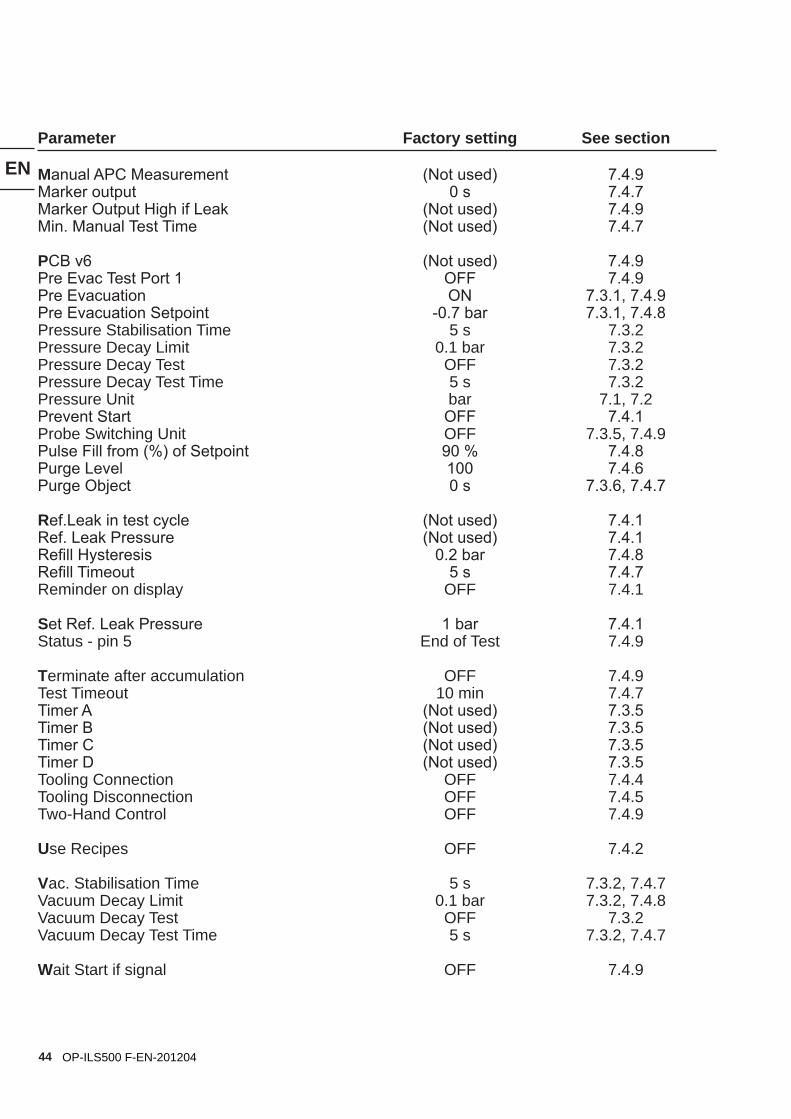
Parameter Factory setting See section
Manual APC Measurement (Not used) 7.4.9Marker output 0 s 7.4.7Marker Output High if Leak (Not used) 7.4.9Min. Manual Test Time (Not used) 7.4.7
PCB v6 (Not used) 7.4.9Pre Evac Test Port 1 OFF 7.4.9Pre Evacuation ON 7.3.1, 7.4.9Pre Evacuation Setpoint -0.7 bar 7.3.1, 7.4.8Pressure Stabilisation Time 5 s 7.3.2Pressure Decay Limit 0.1 bar 7.3.2Pressure Decay Test OFF 7.3.2Pressure Decay Test Time 5 s 7.3.2Pressure Unit bar 7.1, 7.2Prevent Start OFF 7.4.1Probe Switching Unit OFF 7.3.5, 7.4.9Pulse Fill from (%) of Setpoint 90 % 7.4.8Purge Level 100 7.4.6Purge Object 0 s 7.3.6, 7.4.7
Ref.Leak in test cycle (Not used) 7.4.1Ref. Leak Pressure (Not used) 7.4.1Refill Hysteresis 0.2 bar 7.4.8Refill Timeout 5 s 7.4.7Reminder on display OFF 7.4.1
Set Ref. Leak Pressure 1 bar 7.4.1Status - pin 5 End of Test 7.4.9
Terminate after accumulation OFF 7.4.9Test Timeout 10 min 7.4.7Timer A (Not used) 7.3.5Timer B (Not used) 7.3.5Timer C (Not used) 7.3.5Timer D (Not used) 7.3.5Tooling Connection OFF 7.4.4Tooling Disconnection OFF 7.4.5Two-Hand Control OFF 7.4.9
Use Recipes OFF 7.4.2
Vac. Stabilisation Time 5 s 7.3.2, 7.4.7Vacuum Decay Limit 0.1 bar 7.3.2, 7.4.8Vacuum Decay Test OFF 7.3.2Vacuum Decay Test Time 5 s 7.3.2, 7.4.7
Wait Start if signal OFF 7.4.9
45
EN
OP-ILS500 F-EN-201204
8. Fill Cycle Details
The following list shows the individual main steps of a complete test sequence.
Test steps in Italics are optional and turned off as default.
The test steps are described on the following pages. The descriptions are completed with pictures and diagrams.
• Tooling Connection ............................................................................... Section 8.2
• Pre Evacuation and Evacuation Test (Gross Leak Test) ...................... Section 8.3
• Vacuum Decay Test (Gross Leak Test) ................................................ Section 8.4
• Gas Filling ............................................................................................ Section 8.5
• Pressure Decay Test (Gross Leak Test) ............................................... Section 8.6
• Blockage Test ....................................................................................... Section 8.7
• Gas Evacuation .................................................................................... Section 8.9
• Tooling Disconnection. ....................................................................... Section 8.10
46
EN
OP-ILS500 F-EN-201204
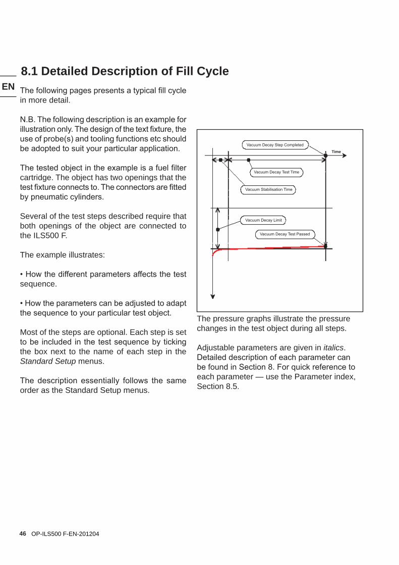
The pressure graphs illustrate the pressure changes in the test object during all steps.
Adjustable parameters are given in italics. Detailed description of each parameter can be found in Section 8. For quick reference to each parameter — use the Parameter index, Section 8.5.
8.1 Detailed Description of Fill CycleThe following pages presents a typical fill cycle in more detail.
N.B. The following description is an example for illustration only. The design of the text fixture, the use of probe(s) and tooling functions etc should be adopted to suit your particular application.
The tested object in the example is a fuel filter cartridge. The object has two openings that the test fixture connects to. The connectors are fitted by pneumatic cylinders.
Several of the test steps described require that both openings of the object are connected to the ILS500 F.
The example illustrates:
• How the different parameters affects the test sequence.
• How the parameters can be adjusted to adapt the sequence to your particular test object.
Most of the steps are optional. Each step is set to be included in the test sequence by ticking the box next to the name of each step in the Standard Setup menus.
The description essentially follows the same order as the Standard Setup menus.
Vacuum
TimeVacuum Decay Step Completed
Vacuum Decay Test Passed
Vacuum Decay Test Time
Vacuum Stabilisation Time
Vacuum Decay Limit
47
EN
OP-ILS500 F-EN-201204
- 0 + 5
-0.7 bar
Atmospheric pressure
Compressed air
Vacuum
Tracer Gas
Test objectPneumatic Tooling cylinder
Pneumatic Tooling cylinder
Compressed air
Vacuum pump
Tracer Gas Exhaust
48
EN
OP-ILS500 F-EN-201204
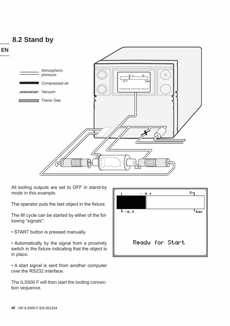
All tooling outputs are set to OFF in stand-by mode in this example.
The operator puts the test object in the fixture.
The fill cycle can be started by either of the fol-lowing “signals”:
• START button is pressed manually.
• Automatically by the signal from a proximity switch in the fixture indicating that the object is in place.
• A start signal is sent from another computer over the RS232 interface.
The ILS500 F will then start the tooling connec-tion sequence.
- 0 + 5
-0.7 bar
8.2 Stand by
Atmospheric pressure
Compressed air
Vacuum
Tracer Gas
49
EN
OP-ILS500 F-EN-201204
- 0 + 5
-0.7 bar
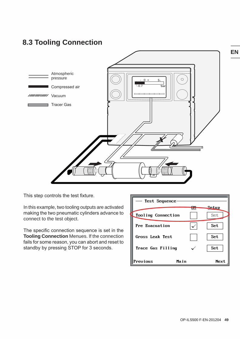
8.3 Tooling Connection
This step controls the test fixture.
In this example, two tooling outputs are activated making the two pneumatic cylinders advance to connect to the test object.
The specific connection sequence is set in the Tooling Connection Menues. If the connection fails for some reason, you can abort and reset to standby by pressing STOP for 3 seconds.
Atmospheric pressure
Compressed air
Vacuum
Tracer Gas
50
EN
OP-ILS500 F-EN-201204
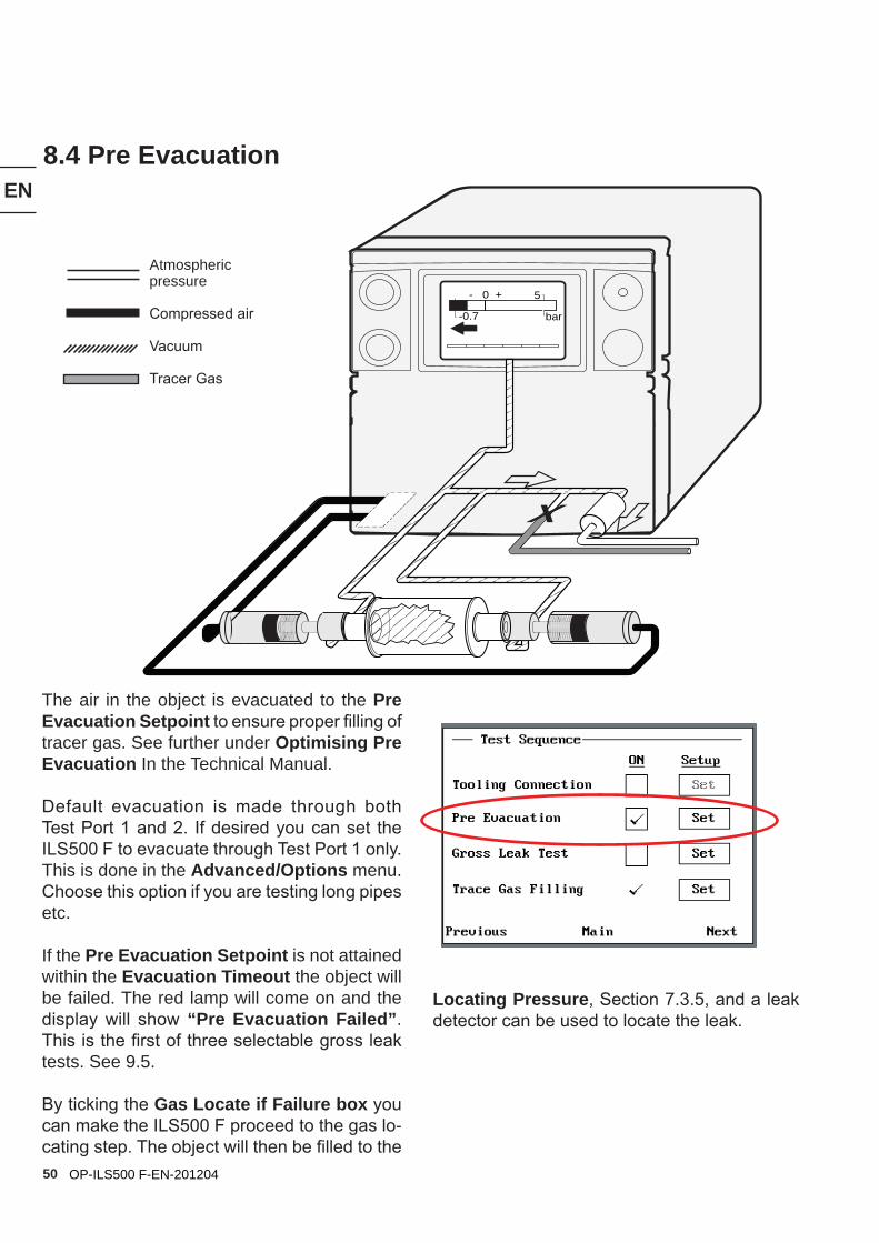
The air in the object is evacuated to the Pre Evacuation Setpoint to ensure proper filling of tracer gas. See further under Optimising Pre Evacuation In the Technical Manual.
Default evacuation is made through both Test Port 1 and 2. If desired you can set the ILS500 F to evacuate through Test Port 1 only. This is done in the Advanced/Options menu. Choose this option if you are testing long pipes etc.
If the Pre Evacuation Setpoint is not attained within the Evacuation Timeout the object will be failed. The red lamp will come on and the display will show “Pre Evacuation Failed”. This is the first of three selectable gross leak tests. See 9.5.
By ticking the Gas Locate if Failure box you can make the ILS500 F proceed to the gas lo-cating step. The object will then be filled to the
- 0 + 5
-0.7 bar
8.4 Pre Evacuation
Atmospheric pressure
Compressed air
Vacuum
Tracer Gas
Locating Pressure, Section 7.3.5, and a leak detector can be used to locate the leak.
51
EN
OP-ILS500 F-EN-201204
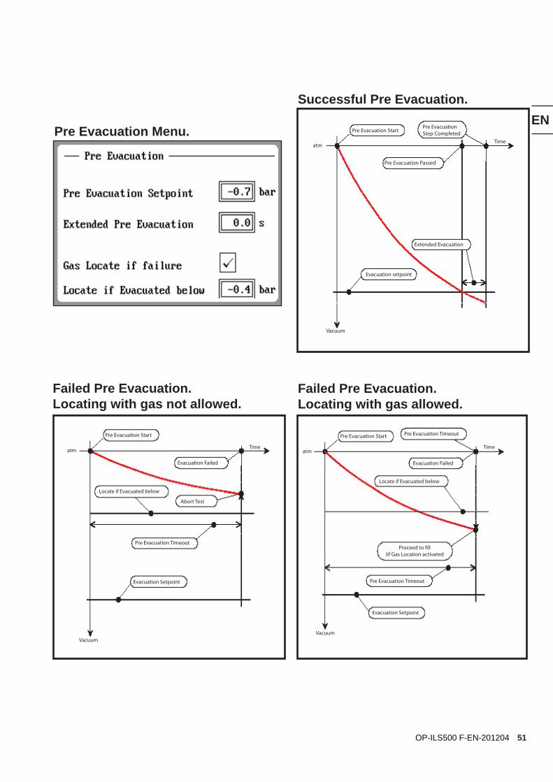
Successful Pre Evacuation.
Failed Pre Evacuation. Locating with gas not allowed.
Failed Pre Evacuation. Locating with gas allowed.
Pre Evacuation StartPre EvacuationStep Completed
Pre Evacuation Passed
Extended Evacuation
Evacuation setpoint
atmTime
Vacuum
atmTime
Vacuum
atm Time
Vacuum
Pre Evacuation Start
Evacuation Failed
Abort Test
Locate if Evacuated below
Pre Evacuation Timeout
Evacuation Setpoint
Pre Evacuation Start
Evacuation Failed
Locate if Evacuated below
Pre Evacuation Timeout
Pre Evacuation Timeout
Evacuation Setpoint
Proceed to fill(if Gas Location activated
Pre Evacuation Menu.
52
EN
OP-ILS500 F-EN-201204
- 0 + 5
-0.7 bar
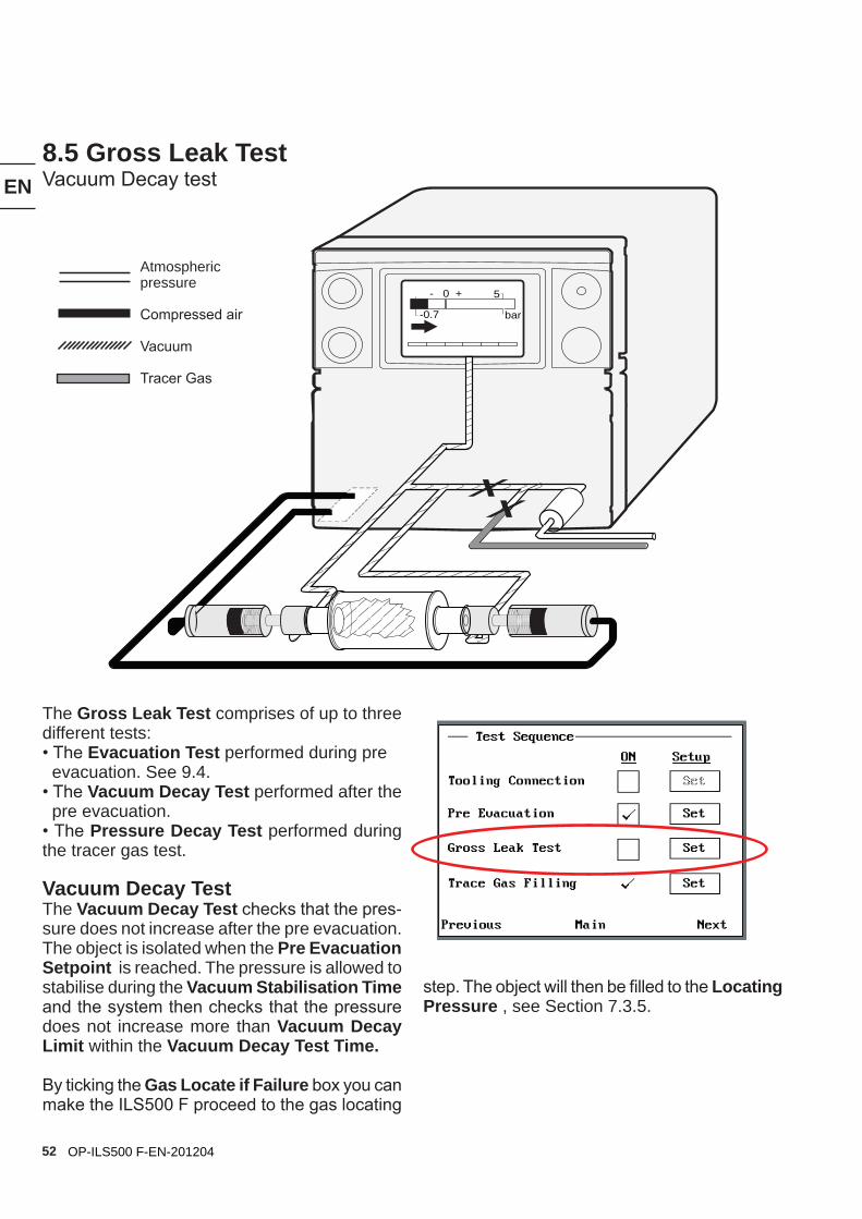
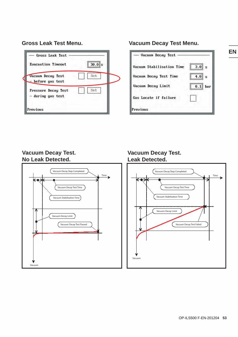
8.5 Gross Leak TestVacuum Decay test
The Gross Leak Test comprises of up to three different tests:• The Evacuation Test performed during pre evacuation. See 9.4.• The Vacuum Decay Test performed after the pre evacuation.• The Pressure Decay Test performed during the tracer gas test.
Vacuum Decay TestThe Vacuum Decay Test checks that the pres-sure does not increase after the pre evacuation. The object is isolated when the Pre Evacuation Setpoint is reached. The pressure is allowed to stabilise during the Vacuum Stabilisation Time and the system then checks that the pressure does not increase more than Vacuum Decay Limit within the Vacuum Decay Test Time.
By ticking the Gas Locate if Failure box you can make the ILS500 F proceed to the gas locating
Atmospheric pressure
Compressed air
Vacuum
Tracer Gas
step. The object will then be filled to the Locating Pressure , see Section 7.3.5.
53
EN
OP-ILS500 F-EN-201204
Vacuum Decay Test. No Leak Detected.
Vacuum Decay Test. Leak Detected.
Vacuum Decay Step Completed
Vacuum Decay Test Time
Vacuum Stabilisation Time
Vacuum Decay Limit
Vacuum Decay Test Failed
Gross Leak Test Menu. Vacuum Decay Test Menu.
Vacuum
Time
Vacuum Decay Step Completed
Vacuum Decay Test Passed
Vacuum Decay Test Time
Vacuum Stabilisation Time
Vacuum Decay Limit
Vacuum
Vacuum
Time
54
EN
OP-ILS500 F-EN-201204
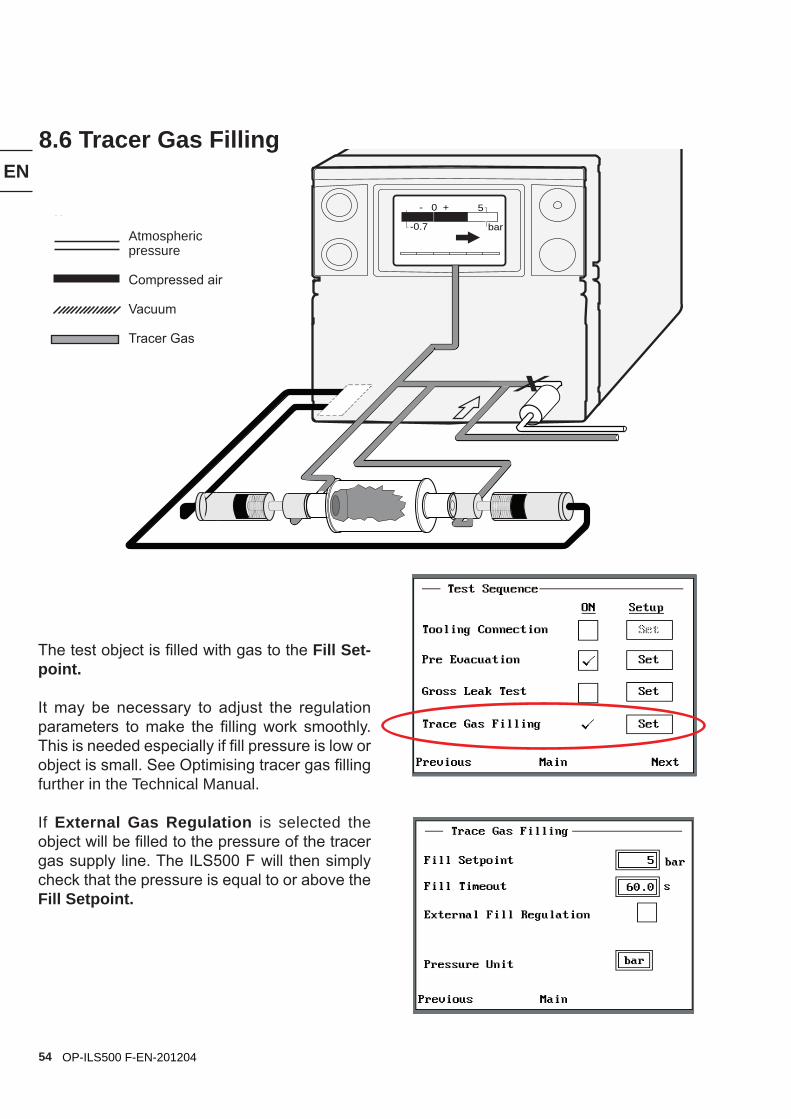
8.6 Tracer Gas Filling
- 0 + 5
-0.7 bar
The test object is filled with gas to the Fill Set-point.
It may be necessary to adjust the regulation parameters to make the filling work smoothly. This is needed especially if fill pressure is low or object is small. See Optimising tracer gas filling further in the Technical Manual.
If External Gas Regulation is selected the object will be filled to the pressure of the tracer gas supply line. The ILS500 F will then simply check that the pressure is equal to or above the Fill Setpoint.
Atmospheric pressure
Compressed air
Vacuum
Tracer Gas
55
EN
OP-ILS500 F-EN-201204
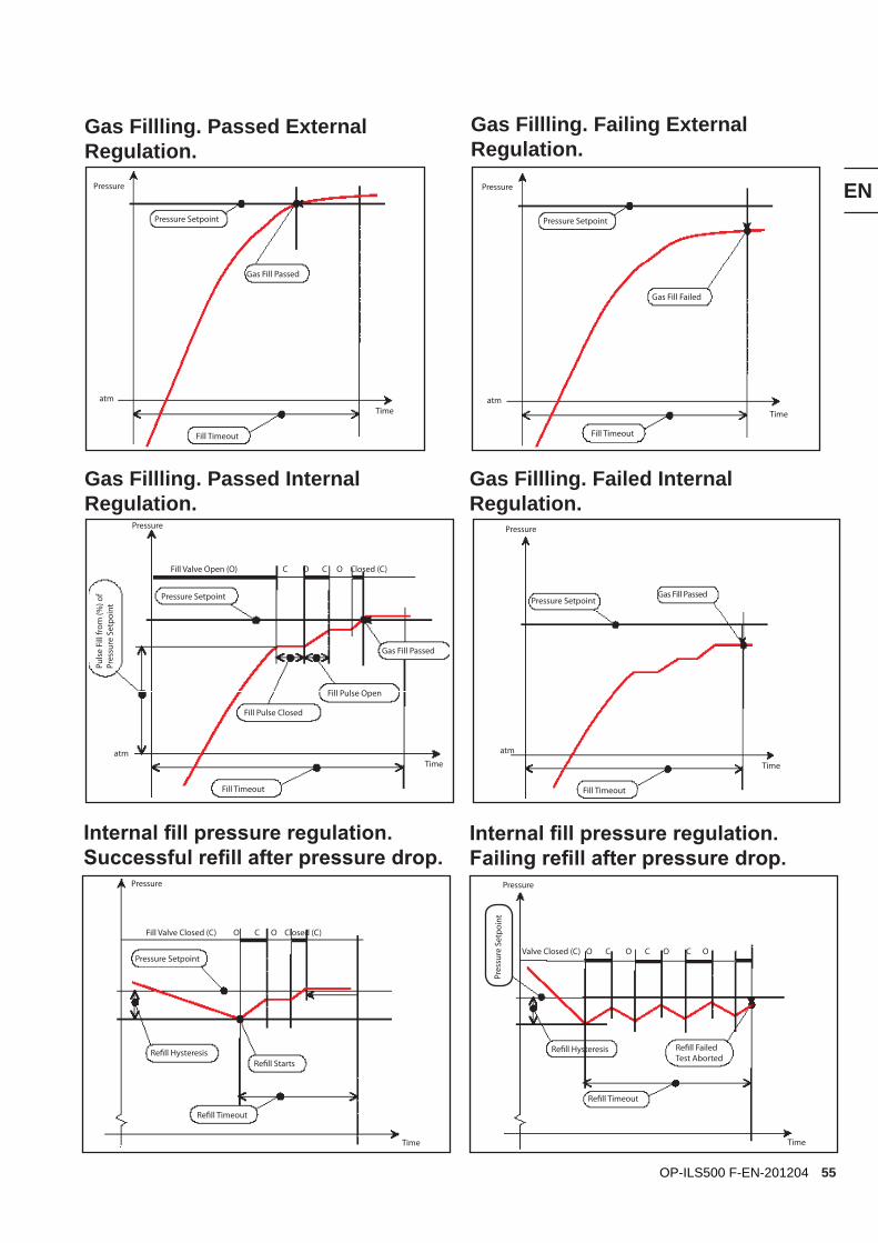
Internal fill pressure regulation. Successful refill after pressure drop.
Gas Fillling. Passed External Regulation.
Gas Fillling. Failing External Regulation.
Gas Fillling. Passed Internal Regulation.
Gas Fillling. Failed Internal Regulation.
Internal fill pressure regulation. Failing refill after pressure drop.
atmTime
Pressure
atm
Time
Pressure
atmTime
Pressure
Gas Fill Passed
Pressure Setpoint
Fill Timeout
Pressure Setpoint
Gas Fill Failed
Fill Timeout
Fill Timeout
Gas Fill Passed
Pressure Setpoint
Fill Pulse Open
Fill Pulse Closed
Puls
e Fi
ll fr
om (%
) of
Pres
sure
Set
poin
t Pressure SetpointGas Fill Passed
Fill Timeout
Fill Valve Open (O) C O C O Closed (C)
Fill Valve Closed (C) O C O Closed (C)
Pressure Setpoint
Refill HysteresisRefill Starts
Refill Timeout
Refill Hysteresis
Refill Timeout
Refill FailedTest Aborted
Valve Closed (C) O C O C O C O
Time
Pressure
Time
Pressure
atm
Time
Pressure
Pres
sure
Set
poin
t
56
EN
OP-ILS500 F-EN-201204
- 0 + 5
-0.7 bar
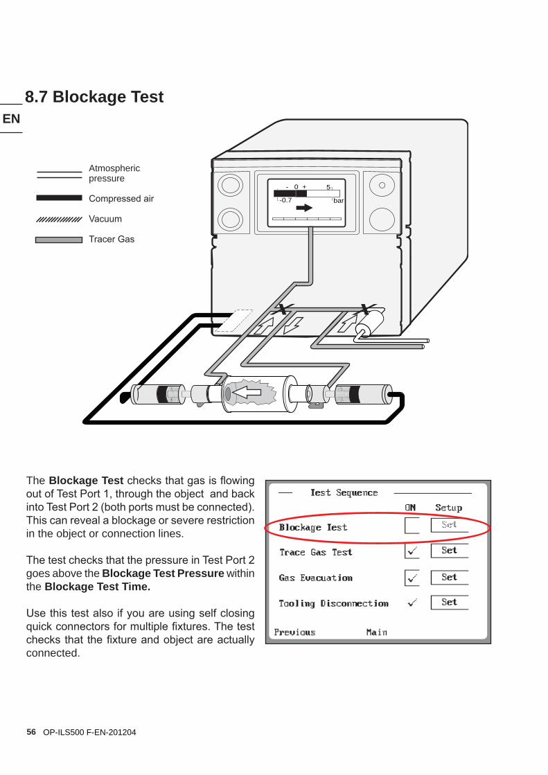
8.7 Blockage Test
The Blockage Test checks that gas is flowing out of Test Port 1, through the object and back into Test Port 2 (both ports must be connected).This can reveal a blockage or severe restriction in the object or connection lines.
The test checks that the pressure in Test Port 2 goes above the Blockage Test Pressure within the Blockage Test Time.
Use this test also if you are using self closing quick connectors for multiple fixtures. The test checks that the fixture and object are actually connected.
Atmospheric pressure
Compressed air
Vacuum
Tracer Gas
57
EN
OP-ILS500 F-EN-201204
Blockage Test. No Blockage Detected.
Blockage Test. Blockage Detected.
atmTime
Pressure
atmTime
Pressure
Blockage Test Passed
Blockage Test Pressure
Blockage Test Time
Blockage Test Time Blockage Test Pressure
Blockage Test Failed
Blockage Test Menu
58
EN
OP-ILS500 F-EN-201204
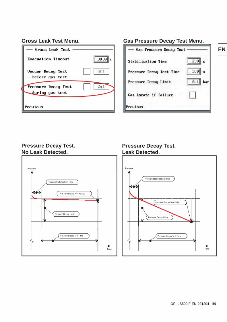
8.8 Gross Leak TestPressure Decay test
- 0 + 5
-0.7 bar
Pressure Decay Test is the third of the selec-table gross leak tests.
The Pressure Decay Test is performed during the tracer gas test.
The object is isolated when the Fill Setpoint is attained. The pressure is allowed to stabilise during the Pressure Stabilisation Time and the system then checks that the pressure does not drop more than the Pressure Decay Limit within the Pressure Decay Test Time.
By ticking the Gas Locate if Failure box you can make the ILS500 F proceed to the gas lo-cating step. The pressure in the object will then be reduced to the Locating Pressure. Section 7.3.5, and you can use your leak detector to locate the leak.
Atmospheric pressure
Compressed air
Vacuum
Tracer Gas
59
EN
OP-ILS500 F-EN-201204
Pressure Decay Test. No Leak Detected.
Pressure Decay Test. Leak Detected.
Time
Pressure
Time
Pressure
Pressure Decay Test Passed
Pressure Stabilisation TimePressure Stabilisation Time
Pressure Decay Test Failed
Pressure Decay LimitPressure Decay Limit
Pressure Decay Test Time Pressure Decay Test Time
Gross Leak Test Menu. Gas Pressure Decay Test Menu.
60
EN
OP-ILS500 F-EN-201204
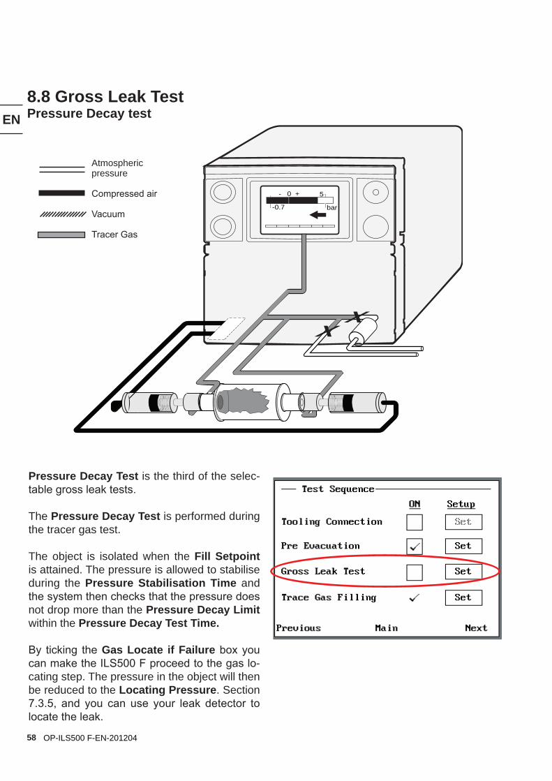
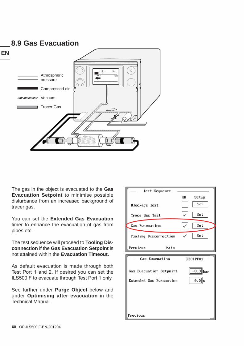
8.9 Gas Evacuation
- 0 + 5
-0.7 bar
The gas in the object is evacuated to the Gas Evacuation Setpoint to minimise possible disturbance from an increased background of tracer gas.
You can set the Extended Gas Evacuation timer to enhance the evacuation of gas from pipes etc.
The test sequence will proceed to Tooling Dis-connection if the Gas Evacuation Setpoint is not attained within the Evacuation Timeout.
As default evacuation is made through both Test Port 1 and 2. If desired you can set the ILS500 F to evacuate through Test Port 1 only.
See further under Purge Object below and under Optimising after evacuation in the Technical Manual.
Atmospheric pressure
Compressed air
Vacuum
Tracer Gas
61
EN
OP-ILS500 F-EN-201204
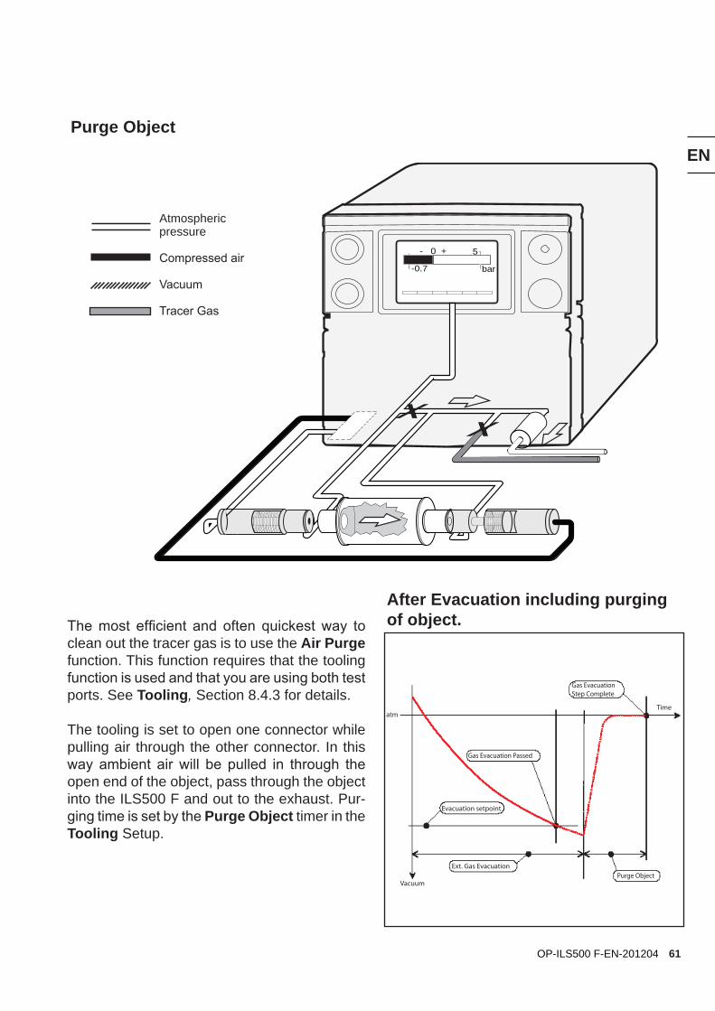
Purge Object
- 0 + 5
-0.7 bar
Time
Vacuum
atm
After Evacuation including purging of object.
Evacuation setpoint
Ext. Gas Evacuation
Gas Evacuation Passed
Gas Evacuation Step Complete
Purge Object
The most efficient and often quickest way to clean out the tracer gas is to use the Air Purge function. This function requires that the tooling function is used and that you are using both test ports. See Tooling, Section 8.4.3 for details.
The tooling is set to open one connector while pulling air through the other connector. In this way ambient air will be pulled in through the open end of the object, pass through the object into the ILS500 F and out to the exhaust. Pur-ging time is set by the Purge Object timer in the Tooling Setup.
Atmospheric pressure
Compressed air
Vacuum
Tracer Gas
62
EN
OP-ILS500 F-EN-201204
- 0 + 5
-0.7 bar
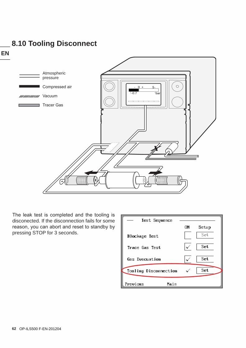
8.10 Tooling Disconnect
The leak test is completed and the tooling is disconected. If the disconnection fails for some reason, you can abort and reset to standby by pressing STOP for 3 seconds.
Atmospheric pressure
Compressed air
Vacuum
Tracer Gas
63
EN
OP-ILS500 F-EN-201204
9. Accessories and Spare Parts
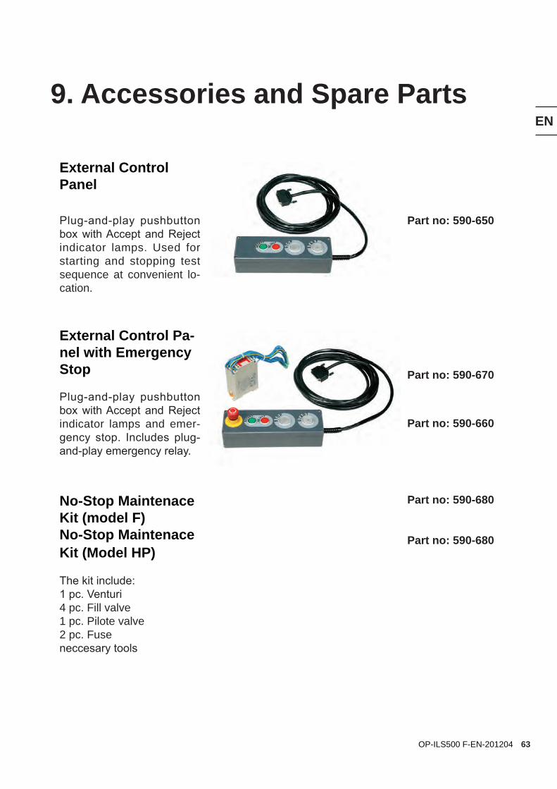
External Control Panel
Part no: 590-650Plug-and-play pushbutton box with Accept and Reject indicator lamps. Used for starting and stopping test sequence at convenient lo-cation.
External Control Pa-nel with Emergency Stop Part no: 590-670
Plug-and-play pushbutton box with Accept and Reject indicator lamps and emer-gency stop. Includes plug-and-play emergency relay.
Part no: 590-660
No-Stop Maintenace Kit (model F) No-Stop Maintenace Kit (Model HP)
The kit include:1 pc. Venturi4 pc. Fill valve1 pc. Pilote valve2 pc. Fuseneccesary tools
Part no: 590-680
Part no: 590-680
64
EN
OP-ILS500 F-EN-201204
10.1 How To Contact INFICONFor Sales and Customer Service contact nearest INFICON Service Center. The addressis found on the website: www.inficon.com
If you are experiencing a problem with your in-strument, please have the following information readily available:
• The serial number and firmware version for your instrument,
• A description of your problem,
• An explanation of any corrective action that you may have already attempted, and the exact wording of any error messages that you may have received.
10.2 Returning Your Instrument to INFICONPlease use the Product Return Form which was included with the product at delivery.
10. Support by INFICON
Do not return any component of your instrument to INFICON without first speaking with a Custo-mer Support Representative. You must obtain a Return Material Authorization (RMA) number from the Customer Support Representative.
If you deliver a package to INFICON without an RMA number, your package will be held and you will be contacted. This will result in delays in servicing your instrument.
Prior to being given an RMA number, you may be required to complete a Declaration Of Con-tamination (DOC) form if your instrument has been exposed to process materials. DOC forms must be approved by INFICON before an RMA number is issued. INFICON may require that the instrument be sent to a designated decontamina-tion facility, not to the factory.
65
EN
OP-ILS500 F-EN-201204
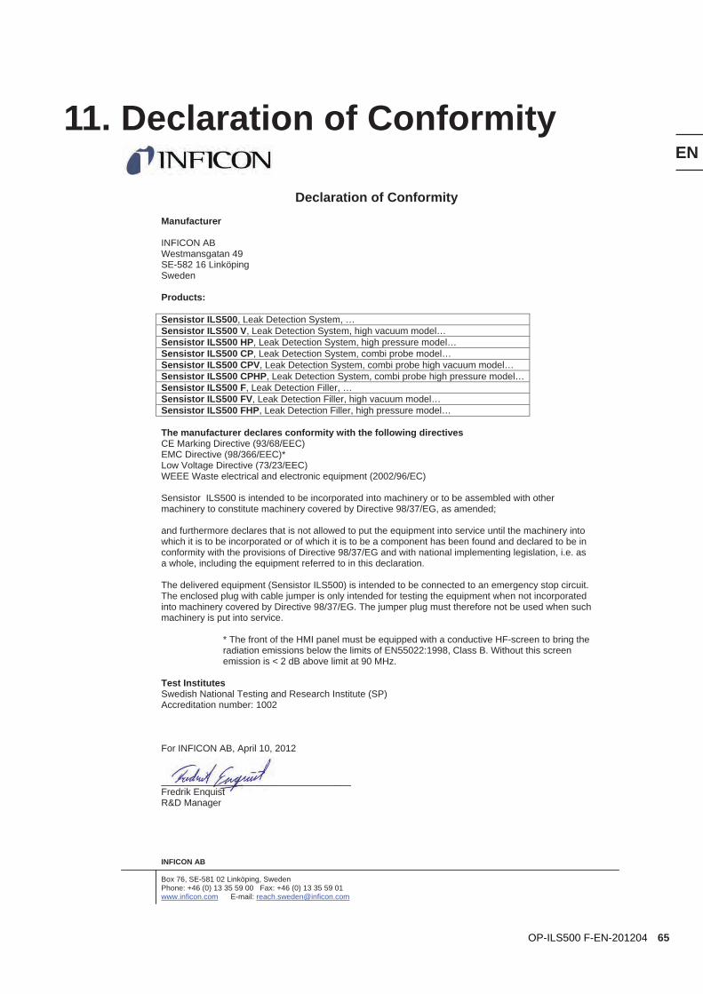
11. Declaration of Conformity
INFICON AB
Box 76, SE-581 02 Linköping, Sweden Phone: +46 (0) 13 35 59 00 Fax: +46 (0) 13 35 59 01 www.inficon.com E-mail: [email protected]
Declaration of Conformity Manufacturer
INFICON AB Westmansgatan 49 SE-582 16 Linköping Sweden
Products:
Sensistor ILS500, Leak Detection System, …Sensistor ILS500 V, Leak Detection System, high vacuum model…Sensistor ILS500 HP, Leak Detection System, high pressure model…Sensistor ILS500 CP, Leak Detection System, combi probe model…Sensistor ILS500 CPV, Leak Detection System, combi probe high vacuum model…Sensistor ILS500 CPHP, Leak Detection System, combi probe high pressure model…Sensistor ILS500 F, Leak Detection Filler, …Sensistor ILS500 FV, Leak Detection Filler, high vacuum model…Sensistor ILS500 FHP, Leak Detection Filler, high pressure model…
The manufacturer declares conformity with the following directives CE Marking Directive (93/68/EEC) EMC Directive (98/366/EEC)* Low Voltage Directive (73/23/EEC) WEEE Waste electrical and electronic equipment (2002/96/EC)
Sensistor ILS500 is intended to be incorporated into machinery or to be assembled with other machinery to constitute machinery covered by Directive 98/37/EG, as amended;
and furthermore declares that is not allowed to put the equipment into service until the machinery into which it is to be incorporated or of which it is to be a component has been found and declared to be in conformity with the provisions of Directive 98/37/EG and with national implementing legislation, i.e. as a whole, including the equipment referred to in this declaration.
The delivered equipment (Sensistor ILS500) is intended to be connected to an emergency stop circuit. The enclosed plug with cable jumper is only intended for testing the equipment when not incorporated into machinery covered by Directive 98/37/EG. The jumper plug must therefore not be used when such machinery is put into service.
* The front of the HMI panel must be equipped with a conductive HF-screen to bring the radiation emissions below the limits of EN55022:1998, Class B. Without this screen emission is < 2 dB above limit at 90 MHz.
Test Institutes Swedish National Testing and Research Institute (SP) Accreditation number: 1002
For INFICON AB, April 10, 2012
____________________________________ Fredrik Enquist R&D Manager
66
EN
OP-ILS500 F-EN-201204
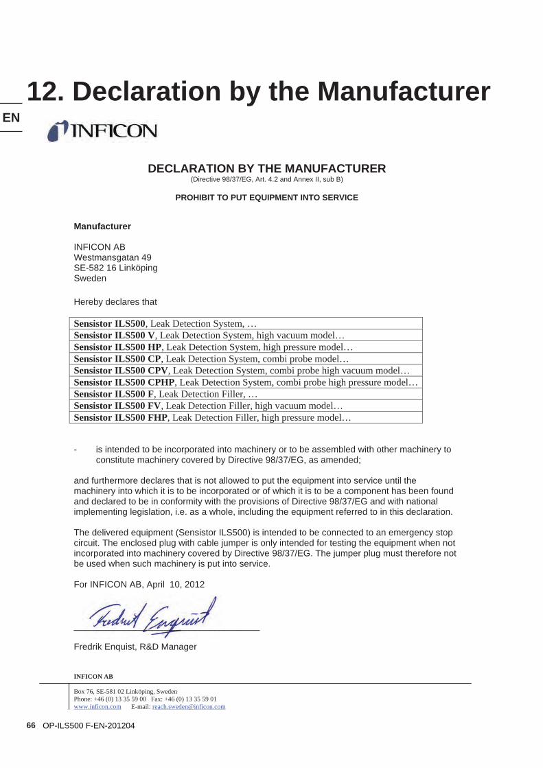
12. Declaration by the Manufacturer
INFICON AB
Box 76, SE-581 02 Linköping, Sweden Phone: +46 (0) 13 35 59 00 Fax: +46 (0) 13 35 59 01 www.inficon.com E-mail: [email protected]
DECLARATION BY THE MANUFACTURER (Directive 98/37/EG, Art. 4.2 and Annex II, sub B)
PROHIBIT TO PUT EQUIPMENT INTO SERVICE
Manufacturer
INFICON AB Westmansgatan 49 SE-582 16 Linköping Sweden
Hereby declares that
Sensistor ILS500, Leak Detection System, …Sensistor ILS500 V, Leak Detection System, high vacuum model…Sensistor ILS500 HP, Leak Detection System, high pressure model…Sensistor ILS500 CP, Leak Detection System, combi probe model…Sensistor ILS500 CPV, Leak Detection System, combi probe high vacuum model…Sensistor ILS500 CPHP, Leak Detection System, combi probe high pressure model…Sensistor ILS500 F, Leak Detection Filler, …Sensistor ILS500 FV, Leak Detection Filler, high vacuum model…Sensistor ILS500 FHP, Leak Detection Filler, high pressure model…
- is intended to be incorporated into machinery or to be assembled with other machinery to constitute machinery covered by Directive 98/37/EG, as amended;
and furthermore declares that is not allowed to put the equipment into service until the machinery into which it is to be incorporated or of which it is to be a component has been found and declared to be in conformity with the provisions of Directive 98/37/EG and with national implementing legislation, i.e. as a whole, including the equipment referred to in this declaration.
The delivered equipment (Sensistor ILS500) is intended to be connected to an emergency stop circuit. The enclosed plug with cable jumper is only intended for testing the equipment when not incorporated into machinery covered by Directive 98/37/EG. The jumper plug must therefore not be used when such machinery is put into service.
For INFICON AB, April 10, 2012
_____________________________________
Fredrik Enquist, R&D Manager
67
EN
OP-ILS500 F-EN-201204
Disposal of product when taken out of serviceAccording to EU legislation, this product must be recovered for separation of materials and may not be disposed of as unsorted municipal waste.
If you wish you can return this INFICON product to the manufacturer for recovery.
The manufacturer has the right to refuse taking back products that are inade-quately packaged and thereby presents safety and/or health risks to the staff.
The manufacturer will not reimburse you for the shipping cost. Shipping address:INFICON ABWestmansgatan 49582 16 LinköpingSweden

68
EN
OP-ILS500 F-EN-201204

69
EN
OP-ILS500 F-EN-201204
INFICON AB, Box 76, SE-581 02 Linköping, SwedenPhone: +46 (0) 13 35 59 00 Fax: +46 (0) 13 35 59 01 www.inficon.com E-mail: [email protected]