Embed Size (px)
Citation preview
SENSiQ™ Elastomer Mount (SEM) Elastomer Mount for SENSiQ™ RTN/RTB 0.25 t … 470 t Load Cell
% Self-centering % Cushions dynamic loads % Stable to shear forces % Simple, robust and flat construction % High resistance to environmental
conditions and chemicals % Easy to assemble % Maintenance-free
Application
For technical measurements the elastomer bearing provides ideal load application to Schenck Process ring torsion load cells.
It is used for all industrial scales such as e.g. bin weighers, roller table scales, crane scales and road weighbridges.
Construction
The Elastomer Mount consists of the pressure piece for load application, the elastomer for self-centering and the base plate for dissipating the load into the supporting construction.
The lateral play must be limited depending on the application. Similarly a lifting restraint should be fitted to prevent lifting.
Function
The weight to be measured is applied to the load cell by means of the pressure piece. The design means that the vertical deflection is extremely small and proportional to the load.
Any lateral forces deform the elastomer in a parallel manner. It automatically will center itself as soon as the lateral force ceases.
A load distribution plate above the pressure piece may be necessary depending on the permissible bear-ing pressure of the load pick-up. This should always be checked for a transition from steel to concrete.
BV-D2044GB
Important Notice:
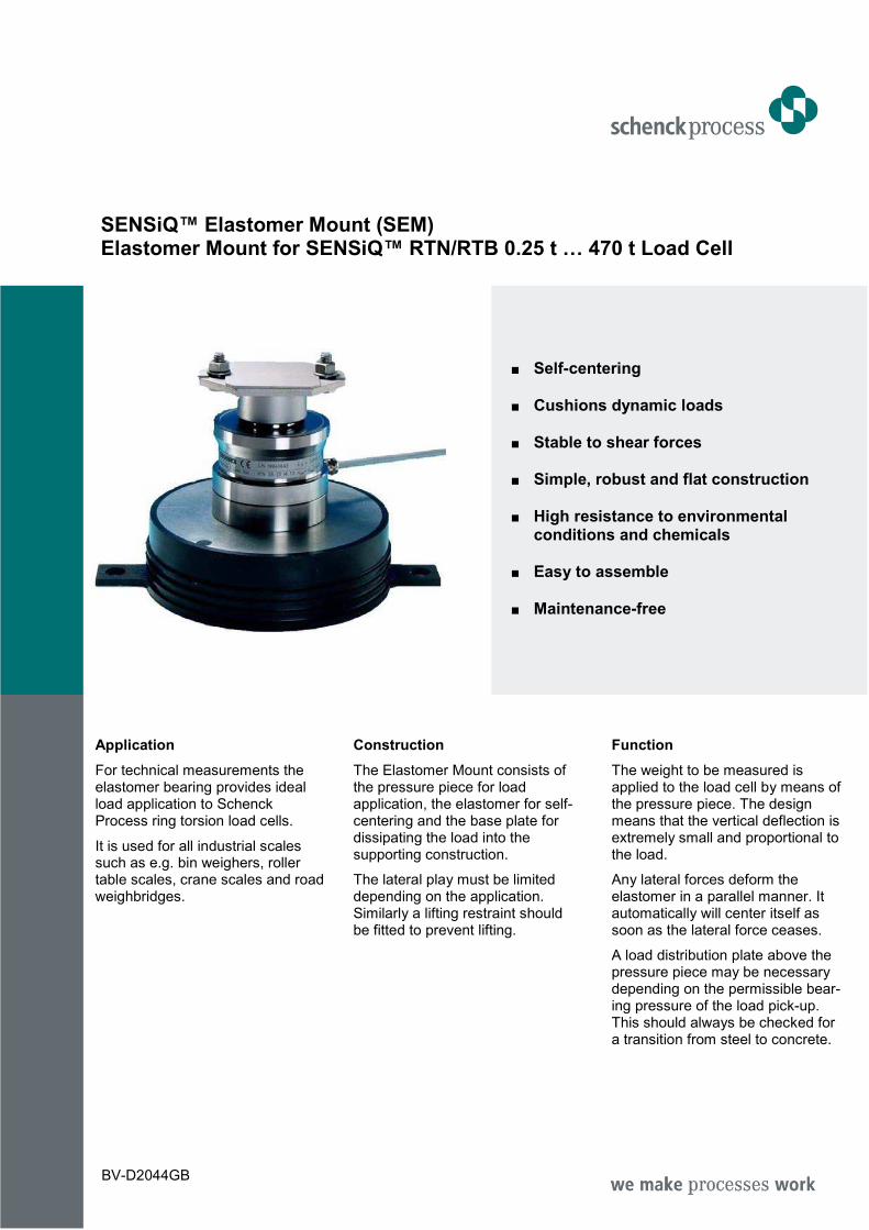
A non-reproducible application of force into the load cell may occur when lifting and re-applying the load application elements, causing measuring errors in the scales overall. The Elastomer Mount therefore may never completely be unloaded. The minimum pre-load should be large enough so that there always is a non-positive con-nection between the load cell and the pressure piece or base plate. - the elastomer is located above
the pressure piece
- the pressure piece is bolted or pinned to the connecting structure by means of two straps on the side
- height compensation (max. 5 mm) is performed using shims
- the bearing is aligned using by moving the base plate that is secured using the fixing pieces to be pinned or bolted on.
Elastomer Mount SEM 0.25 t … 0.50 t for RTB load cells
Shims (5 x 1 mm)
Elastomer
Pressure piece
Load cell Ø80
Base plate Ø85
Fixing piece
Permissible play ±2 mm
Transverse rigidity of the Elastomer Mount SEM 0.25 t: 90 N/mm SEM 0.50 t: 150 N/mm
R = 62.5
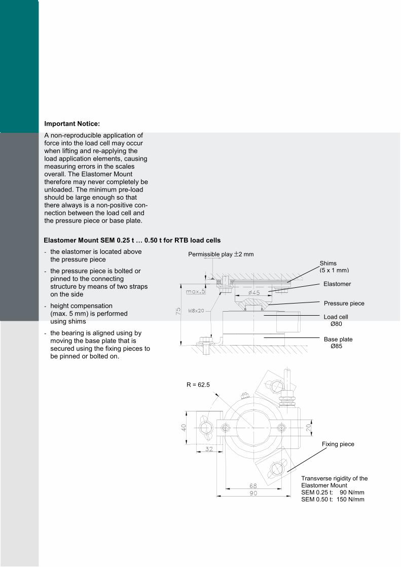
- the elastomer is located above the pressure piece
- the pressure piece is bolted or pinned to the connecting structure by means of two straps on the side
- height compensation (max. 5 mm) is performed using shims
- the SEM is aligned using by moving the base plate that is secured using the fixing pieces to be pinned or bolted on
- it also may be anchored using a centering bolt.
- The head and base of the Elastomer Mount can directly be connected to the connecting structure by bolting them to it. By using the optionale weld-on plates, there is no need to drill and thread the connecting structure. The weld-on plates are welded onto the construc-tion after the load receptor has been aligned. They then hold the bearing with their tap holes. The weld-on plates for the load range 1 t ... 4.7 t can be used above and/or below the SEM. The additional height will be 15 mm each.
- the elastomer is located beneath the load cell
- the pressure piece is secured using a centering piece that is bolted or pinned to the connecting structure
- height compensation (max. 5 mm) is performed using shims
- the SEM is aligned using by moving the elastomer that is secured using straps to be pinned or bolted on
- the head and base of the Elastomer Mount can directly be connected to the connecting structure by bolting them to it. By using the optionale weld-on plates, there is no need to drill and thread the connecting structure. The Elastomer Mount is welded directly to the lower side of the bearing. Additional construc-tion height of the weld-on plate:
- SEM 10 t … 22 t: 20 mm
- SEM 33 t: 25 mm
- Other nominal loads are available on request
Type Dimensions (mm)
SEM A B C D E S G H K L M N P Q
10-22 190 170 25 6 135 90 68 130 60 41 M10x25 M10x25 6 1.4
33 280 250 30 6 175 120 90 168 80 56 M12x25 M12x25 6 1.7
47 350 310 40 10 250 170 130 198 110 63 M16x30 M16x30 6 3.1
68 350 310 40 10 250 170 130 220 110 63 M16x30 M16x30 6 3.1
100 400 360 40 10 300 180 140 239 130 68 M16x30 M16x30 6 4.3
150 510 460 50 10 400 180 140 320 130 81 M20x45 M16x30 8 6.8
220 560 510 50 12 450 260 200 373 180 81 M20x45 M20x45 8 8.7
330 680 620 60 12 550 260 200 427 180 96 M24x40 M24x40 10 7.3
470 780 720 60 12 650 320 240 520 220 115 M24x40 M24x40 13 7.7
Elastomer Mount SEM 1 t … 4.7 t for RTN load cells
Elastomer Mount SEM 10 t … 470 t for RTN load cells
4 Screws M5 x 12 Tightening torque 4 N m
Permissible play ±2 mm
Transverse rigidity of the Elastomer Mount SEM 1 t: 240 N/mm SEM 2.2 t: 240 N/mm SEM 4.7 t: 420 N/mm
Shims (5 x 1 mm) Elastomer
Pressure piece
Load cell Base plate with earthing connection M6 and ventilation borehole
may be anchored with bolts if desired Fixing piece
Q: Transverse rigidity of the Elastomer Mount
Permissible play ±P mm Shims (5 x 1 mm)
Centering piece
Load cell Base plate (>100 t: 2 pieces) with earthing connection M6 Elastomer
Anchoring strap
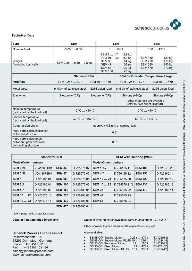
Technical Data
Type SEM SEM SEM
Nominal load 0.25 t ... 0.50 t 1 t ... 100 t 150 t ... 470 t
Weight (including load cell)
SEM 0.25 … 0.50 2.8 kg
SEM 1 … 4.7 2.9 kg SEM 10 … 22 5.3 kg SEM 33 14 kg SEM 47 26 kg SEM 68 29 kg SEM 100 43 kg
SEM 150 120 kg SEM 220 170 kg SEM 330 250 kg SEM 470 410 kg
Standard SEM SEM for Extended Temperature Range
Materials SEM 0.25 t … 4.7 t SEM 10 t … 470 t SEM 0.25 t … 4.7 t SEM 10 t … 470 t
Metal parts entirely of stainless steel S235 galvanized entirely of stainless steel S355 galvanized
Elastomer Neoprene (CR) Neoprene (CR) Silicone (VMQ) Silicone (VMQ)
other materials are available refer to data sheet DDP8483
Nominal temperature (restricted by the load cell)
-10 °C … +40 °C -10 °C … +40 °C
Service temperature (restricted by the load cell)
-30 °C … +100 °C -50 °C … +110 °C
Compression stroke approx. ≤ 0.8 mm at nominal load
max. permissible inclination of the substructure
0.2°
max. permissible angle between upper and lower connecting structure
0.6°
Standard SEM SEM with silicone (VMQ)
Model/Order numbers Model/Order numbers
SEM 0.25 V041386.B01 SEM 33 D 725575.02 SEM 1/2.2 D 726185.11 SEM 100 D 725575.25
SEM 0.50 V041387.B01 SEM 47 D 725575.03 SEM 4.7 D 726185.12 SEM 150 D 726186.11
SEM 1 D 726185.01 SEM 68 D 725575.04 SEM 10 … 22 D 725575.20 SEM 220 D 726186.12
SEM 2.2 D 726185.01 SEM 100 D 725575.05 SEM 10 … 22 D 725575.21*) SEM 330 D 726186.13
SEM 4.7 D 726185.02 SEM 150 D 726186.01 SEM 33 D 725575.22 SEM 470 D 726186.14
SEM 10 … 22 D 725575.10 SEM 220 D 726186.02 SEM 47 D 725575.23
SEM 10 … 22 D 725575.11*) SEM 330 D 726186.03 SEM 68 D 725575.24
SEM 470 D 726186.04
*) Metal parts made of stainless steel
(Load cell not included in delivery) Optional weld-on plates available, refer to data sheet BV-D2228
Other nominal loads and materials available on request.
Also available:
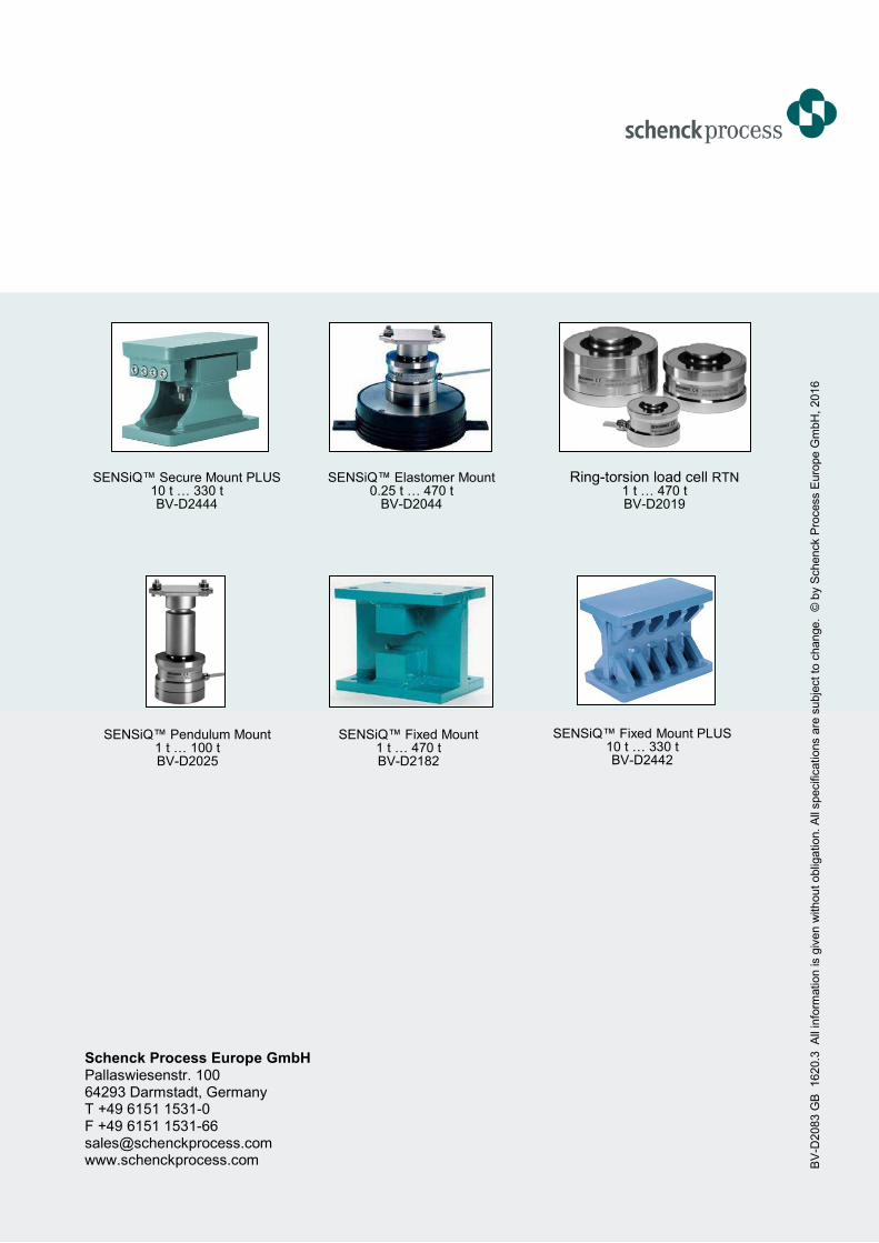
• SENSiQ™ Secure Mount 0.25 t … 470 t (BV-D2083) • SENSiQ™ Secure Mount PLUS 10 t … 330 t (BV-D2444) • SENSiQ™ Pendulum Mount 1 t … 100 t (BV-D2025) • SENSiQ™ Fixed Mount 1 t … 470 t (BV-D2182) • SENSiQ™ Fixed Mount PLUS 10 t … 330 t (BV-D2442)
Schenck Process Europe GmbH Pallaswiesenstr. 100 64293 Darmstadt, Germany Phone: +49 6151 1531-0 Fax: +49 6151 1531-66
[email protected] www.schenckprocess.com
BV
-D2044G
B
1622.2
A
ll in
form
ation is g
iven w
ithout
oblig
ation. A
ll specific
ations a
re s
ubje
ct to
change.
© b
y S
chenck P
rocess E
uro
pe G
mbH
, 2016
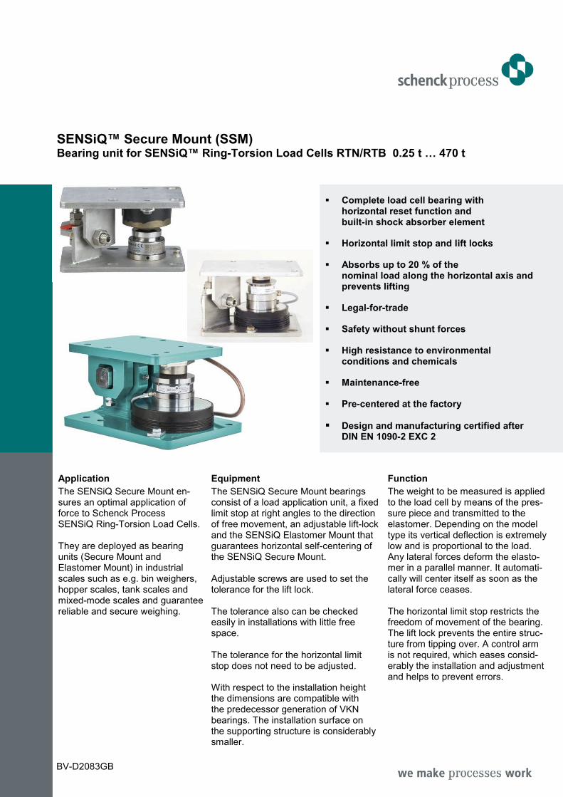
SENSiQ™ Secure Mount (SSM) Bearing unit for SENSiQ™ Ring-Torsion Load Cells RTN/RTB 0.25 t … 470 t
Complete load cell bearing with horizontal reset function and built-in shock absorber element
Horizontal limit stop and lift locks
Absorbs up to 20 % of the nominal load along the horizontal axis and prevents lifting
Legal-for-trade
Safety without shunt forces
High resistance to environmental conditions and chemicals
Maintenance-free
Pre-centered at the factory
Design and manufacturing certified after DIN EN 1090-2 EXC 2
Application
The SENSiQ Secure Mount en-sures an optimal application of force to Schenck Process SENSiQ Ring-Torsion Load Cells. They are deployed as bearing units (Secure Mount and Elastomer Mount) in industrial scales such as e.g. bin weighers, hopper scales, tank scales and mixed-mode scales and guarantee reliable and secure weighing.
Equipment
The SENSiQ Secure Mount bearings consist of a load application unit, a fixed limit stop at right angles to the direction of free movement, an adjustable lift-lock and the SENSiQ Elastomer Mount that guarantees horizontal self-centering of the SENSiQ Secure Mount. Adjustable screws are used to set the tolerance for the lift lock. The tolerance also can be checked easily in installations with little free space. The tolerance for the horizontal limit stop does not need to be adjusted. With respect to the installation height the dimensions are compatible with the predecessor generation of VKN bearings. The installation surface on the supporting structure is considerably smaller.
Function
The weight to be measured is applied to the load cell by means of the pres-sure piece and transmitted to the elastomer. Depending on the model type its vertical deflection is extremely low and is proportional to the load. Any lateral forces deform the elasto-mer in a parallel manner. It automati-cally will center itself as soon as the lateral force ceases. The horizontal limit stop restricts the freedom of movement of the bearing. The lift lock prevents the entire struc-ture from tipping over. A control arm is not required, which eases consid-erably the installation and adjustment and helps to prevent errors.
BV-D2083GB
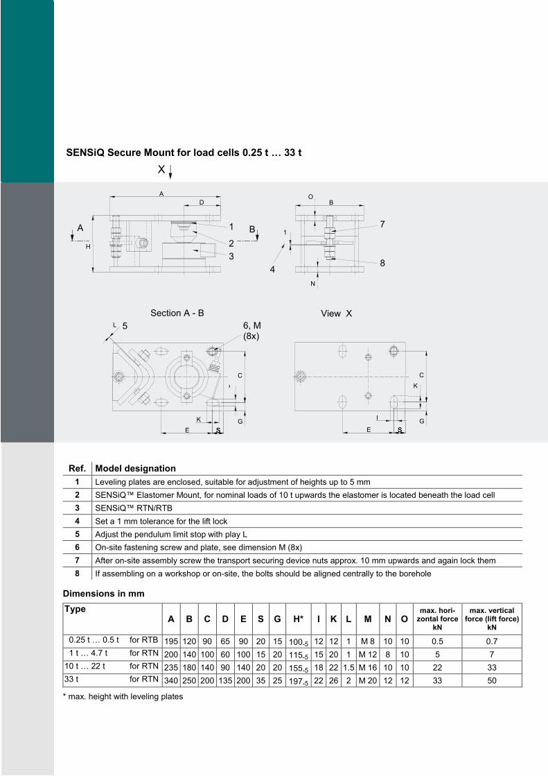
SENSiQ Secure Mount for load cells 0.25 t … 33 t
Ref. Model designation
1 Leveling plates are enclosed, suitable for adjustment of heights up to 5 mm
2 SENSiQ™ Elastomer Mount, for nominal loads of 10 t upwards the elastomer is located beneath the load cell
3 SENSiQ™ RTN/RTB
4 Set a 1 mm tolerance for the lift lock
5 Adjust the pendulum limit stop with play L
6 On-site fastening screw and plate, see dimension M (8x)
7 After on-site assembly screw the transport securing device nuts approx. 10 mm upwards and again lock them
8 If assembling on a workshop or on-site, the bolts should be aligned centrally to the borehole
Dimensions in mm
Type A B C D E S G H* I K L M N O
max. hori-zontal force
kN
max. vertical force (lift force)
kN
0.25 t … 0.5 t for RTB 195 120 90 65 90 20 15 100-5 12 12 1 M 8 10 10 0.5 0.7
1 t … 4.7 t for RTN 200 140 100 60 100 15 20 115-5 15 20 1 M 12 8 10 5 7
10 t … 22 t for RTN 235 180 140 90 140 20 20 155-5 18 22 1.5 M 16 10 10 22 33
33 t for RTN 340 250 200 135 200 35 25 197-5 22 26 2 M 20 12 12 33 50
* max. height with leveling plates
B
B
A
D A
G E
5 L
H
C
6, M (8x)
2
3
1
8 4
1 7
S S
C
E S S G
X
K
I
I
K
N
O
Section A - B View X
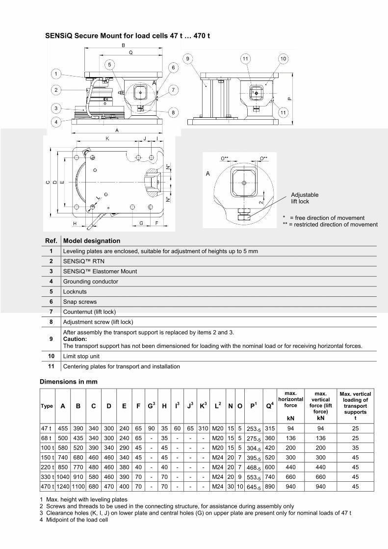
SENSiQ Secure Mount for load cells 47 t … 470 t
Ref. Model designation
1 Leveling plates are enclosed, suitable for adjustment of heights up to 5 mm
2 SENSiQ™ RTN
3 SENSiQ™ Elastomer Mount
4 Grounding conductor
5 Locknuts
6 Snap screws
7 Counternut (lift lock)
8 Adjustment screw (lift lock)
9 After assembly the transport support is replaced by items 2 and 3. Caution: The transport support has not been dimensioned for loading with the nominal load or for receiving horizontal forces.
10 Limit stop unit
11 Centering plates for transport and installation
Dimensions in mm
Type A B C D E F G3 H I
3 J
3 K
3 L
2 N O P
1 Q
4
max. horizontal
force
kN
max. vertical
force (lift force)
kN
Max. vertical loading of transport supports
t
47 t 455 390 340 300 240 65 90 35 60 65 310 M20 15 5 253-5 315 94 94 25
68 t 500 435 340 300 240 65 - 35 - - - M20 15 5 275-5 360 136 136 25
100 t 580 520 390 340 290 45 - 45 - - - M20 15 5 304-5 420 200 200 35
150 t 740 680 460 460 340 45 - 45 - - - M24 20 7 395-5 520 300 300 45
220 t 850 770 480 460 380 40 - 40 - - - M24 20 7 468-5 600 440 440 45
330 t 1040 910 580 460 390 70 - 70 - - - M24 20 9 553-5 740 660 660 45
470 t 1240 1100 680 470 400 70 - 70 - - - M24 30 10 645-5 890 940 940 45
1 Max. height with leveling plates 2 Screws and threads to be used in the connecting structure, for assistance during assembly only 3 Clearance holes (K, I, J) on lower plate and central holes (G) on upper plate are present only for nominal loads of 47 t 4 Midpoint of the load cell
* = free direction of movement ** = restricted direction of movement
Adjustable lift lock
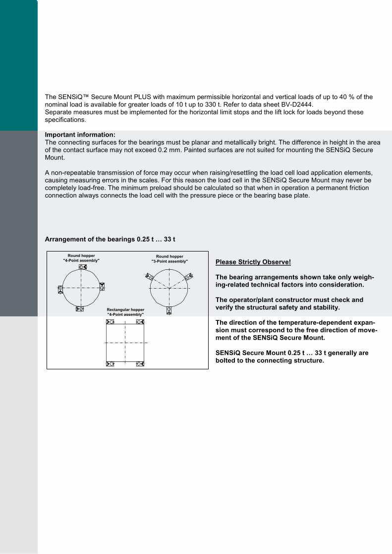
The SENSiQ™ Secure Mount PLUS with maximum permissible horizontal and vertical loads of up to 40 % of the nominal load is available for greater loads of 10 t up to 330 t. Refer to data sheet BV-D2444. Separate measures must be implemented for the horizontal limit stops and the lift lock for loads beyond these specifications. Important information: The connecting surfaces for the bearings must be planar and metallically bright. The difference in height in the area of the contact surface may not exceed 0.2 mm. Painted surfaces are not suited for mounting the SENSiQ Secure Mount. A non-repeatable transmission of force may occur when raising/resettling the load cell load application elements, causing measuring errors in the scales. For this reason the load cell in the SENSiQ Secure Mount may never be completely load-free. The minimum preload should be calculated so that when in operation a permanent friction connection always connects the load cell with the pressure piece or the bearing base plate.
Arrangement of the bearings 0.25 t … 33 t
Please Strictly Observe! The bearing arrangements shown take only weigh-ing-related technical factors into consideration. The operator/plant constructor must check and verify the structural safety and stability. The direction of the temperature-dependent expan-sion must correspond to the free direction of move-ment of the SENSiQ Secure Mount. SENSiQ Secure Mount 0.25 t … 33 t generally are bolted to the connecting structure.
Round hopper
"4-Point assembly" Round hopper
"3-Point assembly"
Rectangular hopper
"4-Point assembly"
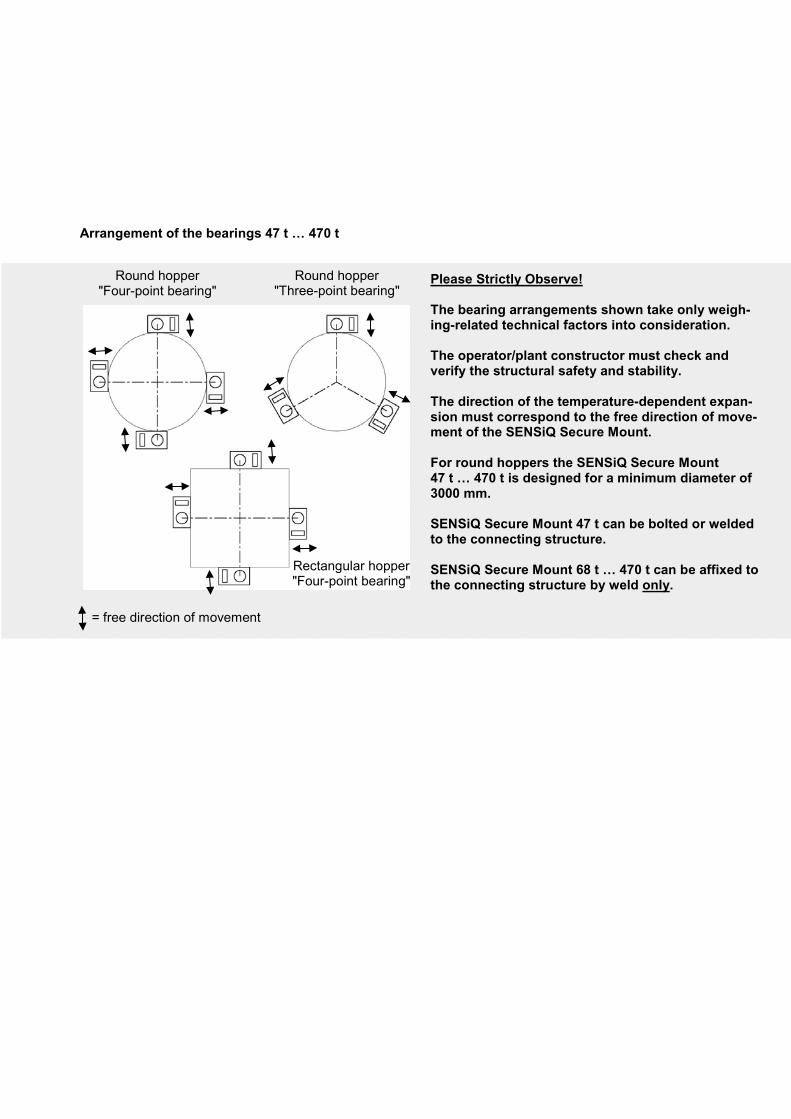
Arrangement of the bearings 47 t … 470 t
Please Strictly Observe! The bearing arrangements shown take only weigh-ing-related technical factors into consideration. The operator/plant constructor must check and verify the structural safety and stability. The direction of the temperature-dependent expan-sion must correspond to the free direction of move-ment of the SENSiQ Secure Mount. For round hoppers the SENSiQ Secure Mount 47 t … 470 t is designed for a minimum diameter of 3000 mm. SENSiQ Secure Mount 47 t can be bolted or welded to the connecting structure. SENSiQ Secure Mount 68 t … 470 t can be affixed to the connecting structure by weld only.
= free direction of movement
Round hopper "Four-point bearing"
Round hopper "Three-point bearing"
Rectangular hopper "Four-point bearing"
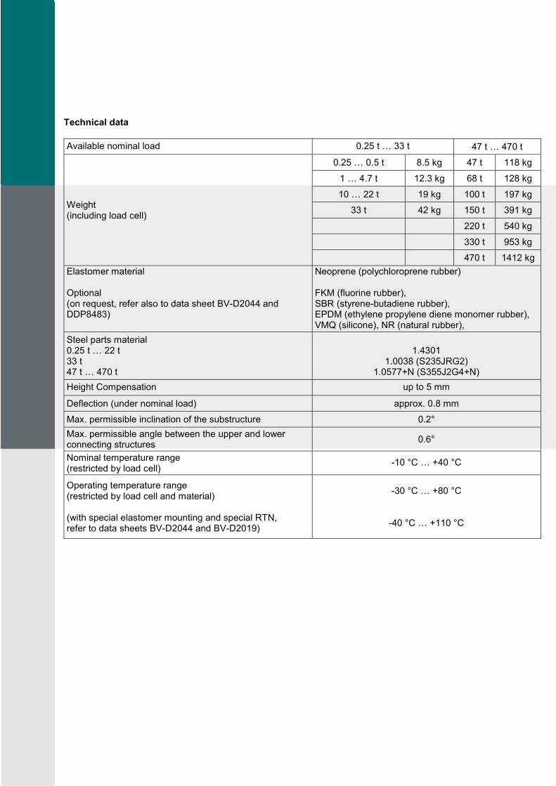
Technical data
Available nominal load 0.25 t … 33 t 47 t … 470 t
Weight (including load cell)
0.25 … 0.5 t 8.5 kg 47 t 118 kg
1 … 4.7 t 12.3 kg 68 t 128 kg
10 … 22 t 19 kg 100 t 197 kg
33 t 42 kg 150 t 391 kg
220 t 540 kg
330 t 953 kg
470 t 1412 kg
Elastomer material Optional (on request, refer also to data sheet BV-D2044 and DDP8483)
Neoprene (polychloroprene rubber) FKM (fluorine rubber), SBR (styrene-butadiene rubber), EPDM (ethylene propylene diene monomer rubber), VMQ (silicone), NR (natural rubber),
Steel parts material 0.25 t … 22 t 33 t 47 t … 470 t
1.4301
1.0038 (S235JRG2) 1.0577+N (S355J2G4+N)
Height Compensation up to 5 mm
Deflection (under nominal load) approx. 0.8 mm
Max. permissible inclination of the substructure 0.2°
Max. permissible angle between the upper and lower connecting structures
0.6°
Nominal temperature range (restricted by load cell)
-10 °C … +40 °C
Operating temperature range (restricted by load cell and material) (with special elastomer mounting and special RTN, refer to data sheets BV-D2044 and BV-D2019)
-30 °C … +80 °C
-40 °C … +110 °C
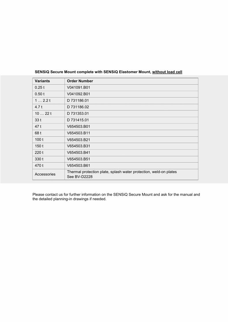
SENSiQ Secure Mount complete with SENSiQ Elastomer Mount, without load cell
Variants Order Number
0.25 t V041091.B01
0.50 t V041092.B01
1 … 2.2 t D 731186.01
4.7 t D 731186.02
10 … 22 t D 731353.01
33 t D 731415.01
47 t V654503.B01
68 t V654503.B11
100 t V654503.B21
150 t V654503.B31
220 t V654503.B41
330 t V654503.B51
470 t V654503.B61
Accessories Thermal protection plate, splash water protection, weld-on plates
See BV-D2228
Please contact us for further information on the SENSiQ Secure Mount and ask for the manual and the detailed planning-in drawings if needed.
BV
-D2083 G
B
1620.3
A
ll in
form
ation is g
iven w
ithout oblig
ation. A
ll specific
ations a
re s
ubje
ct to
change.
© b
y S
chenck P
rocess E
uro
pe G
mbH
, 2016
Schenck Process Europe GmbH Pallaswiesenstr. 100 64293 Darmstadt, Germany T +49 6151 1531-0 F +49 6151 1531-66 [email protected] www.schenckprocess.com
SENSiQ™ Elastomer Mount 0.25 t … 470 t
BV-D2044
Ring-torsion load cell RTN 1 t … 470 t BV-D2019
SENSiQ™ Pendulum Mount 1 t … 100 t BV-D2025
SENSiQ™ Fixed Mount 1 t … 470 t BV-D2182
SENSiQ™ Fixed Mount PLUS 10 t … 330 t BV-D2442
SENSiQ™ Secure Mount PLUS 10 t … 330 t BV-D2444
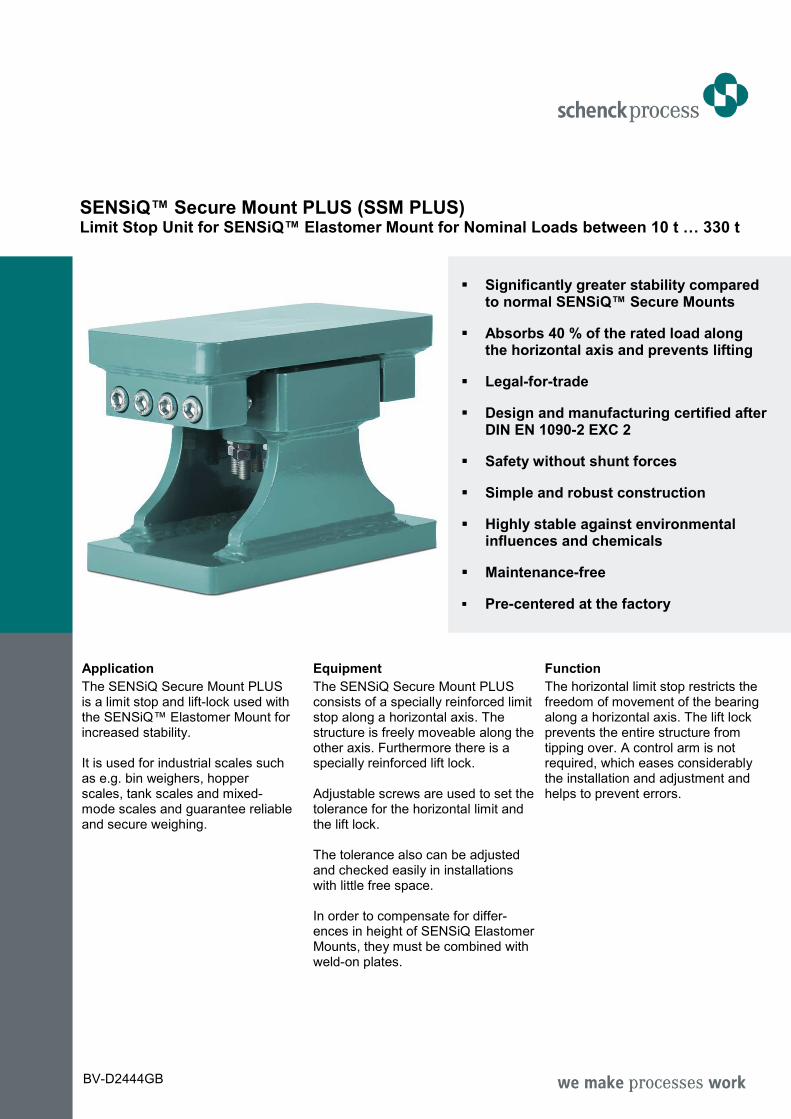
SENSiQ™ Secure Mount PLUS (SSM PLUS) Limit Stop Unit for SENSiQ™ Elastomer Mount for Nominal Loads between 10 t … 330 t
Significantly greater stability compared to normal SENSiQ™ Secure Mounts
Absorbs 40 % of the rated load along the horizontal axis and prevents lifting
Legal-for-trade
Design and manufacturing certified after DIN EN 1090-2 EXC 2
Safety without shunt forces
Simple and robust construction
Highly stable against environmental influences and chemicals
Maintenance-free
Pre-centered at the factory
Application
The SENSiQ Secure Mount PLUS is a limit stop and lift-lock used with the SENSiQ™ Elastomer Mount for increased stability. It is used for industrial scales such as e.g. bin weighers, hopper scales, tank scales and mixed-mode scales and guarantee reliable and secure weighing.
Equipment
The SENSiQ Secure Mount PLUS consists of a specially reinforced limit stop along a horizontal axis. The structure is freely moveable along the other axis. Furthermore there is a specially reinforced lift lock. Adjustable screws are used to set the tolerance for the horizontal limit and the lift lock. The tolerance also can be adjusted and checked easily in installations with little free space. In order to compensate for differ-ences in height of SENSiQ Elastomer Mounts, they must be combined with weld-on plates.
Function
The horizontal limit stop restricts the freedom of movement of the bearing along a horizontal axis. The lift lock prevents the entire structure from tipping over. A control arm is not required, which eases considerably the installation and adjustment and helps to prevent errors.
BV-D2444GB
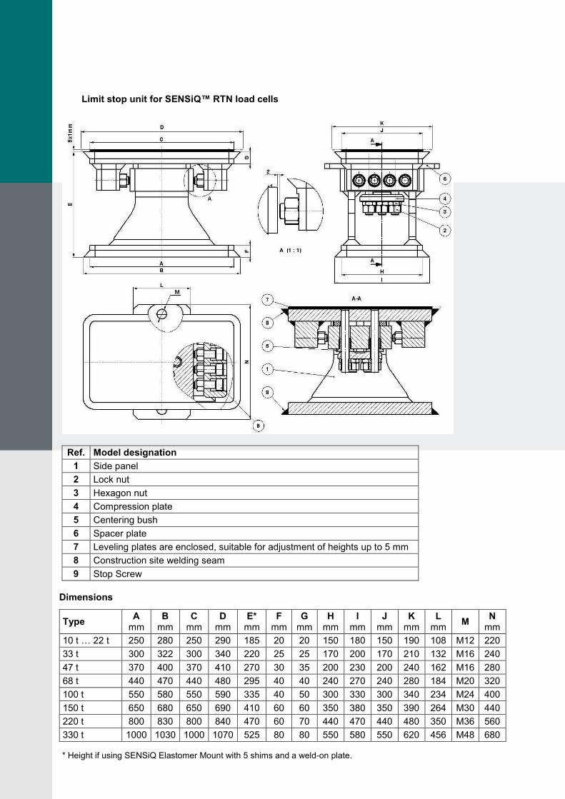
Limit stop unit for SENSiQ™ RTN load cells
Ref. Model designation
1 Side panel
2 Lock nut
3 Hexagon nut
4 Compression plate
5 Centering bush
6 Spacer plate
7 Leveling plates are enclosed, suitable for adjustment of heights up to 5 mm
8 Construction site welding seam
9 Stop Screw
Dimensions
Type A
mm B
mm C
mm D
mm E*
mm F
mm G
mm H
mm I
mm J
mm K
mm L
mm M
N mm
10 t … 22 t 250 280 250 290 185 20 20 150 180 150 190 108 M12 220
33 t 300 322 300 340 220 25 25 170 200 170 210 132 M16 240
47 t 370 400 370 410 270 30 35 200 230 200 240 162 M16 280
68 t 440 470 440 480 295 40 40 240 270 240 280 184 M20 320
100 t 550 580 550 590 335 40 50 300 330 300 340 234 M24 400
150 t 650 680 650 690 410 60 60 350 380 350 390 264 M30 440
220 t 800 830 800 840 470 60 70 440 470 440 480 350 M36 560
330 t 1000 1030 1000 1070 525 80 80 550 580 550 620 456 M48 680
* Height if using SENSiQ Elastomer Mount with 5 shims and a weld-on plate.
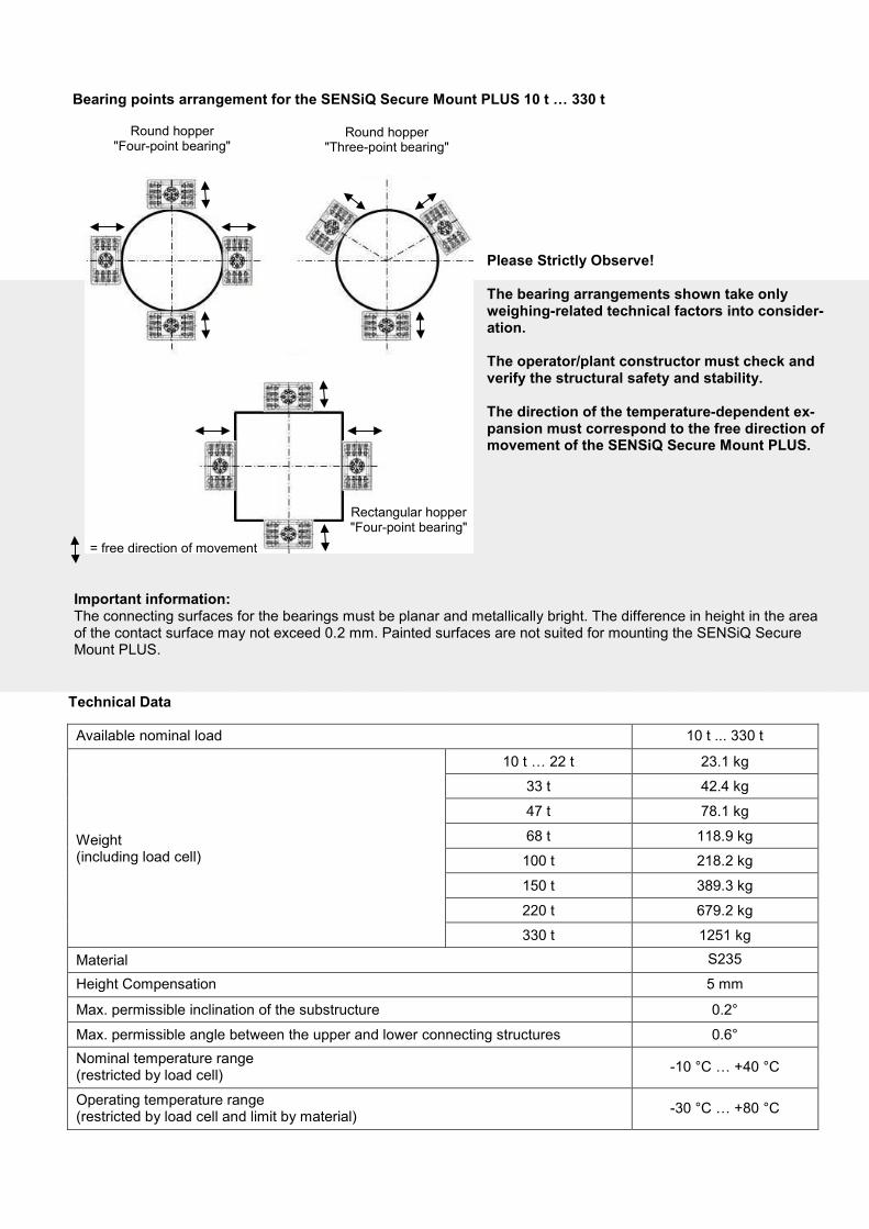
Bearing points arrangement for the SENSiQ Secure Mount PLUS 10 t … 330 t
Technical Data
Available nominal load 10 t ... 330 t
Weight (including load cell)
10 t … 22 t 23.1 kg
33 t 42.4 kg
47 t 78.1 kg
68 t 118.9 kg
100 t 218.2 kg
150 t 389.3 kg
220 t 679.2 kg
330 t 1251 kg
Material S235
Height Compensation 5 mm
Max. permissible inclination of the substructure 0.2°
Max. permissible angle between the upper and lower connecting structures 0.6°
Nominal temperature range (restricted by load cell)
-10 °C … +40 °C
Operating temperature range (restricted by load cell and limit by material)
-30 °C … +80 °C
Please Strictly Observe! The bearing arrangements shown take only weighing-related technical factors into consider-ation. The operator/plant constructor must check and verify the structural safety and stability. The direction of the temperature-dependent ex-pansion must correspond to the free direction of movement of the SENSiQ Secure Mount PLUS.
Important information: The connecting surfaces for the bearings must be planar and metallically bright. The difference in height in the area of the contact surface may not exceed 0.2 mm. Painted surfaces are not suited for mounting the SENSiQ Secure Mount PLUS.
= free direction of movement
Rectangular hopper "Four-point bearing"
Round hopper "Four-point bearing"
Round hopper "Three-point bearing"
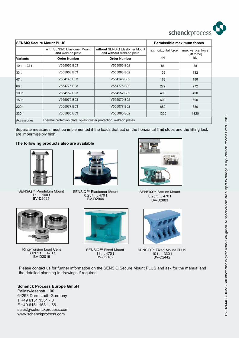
SENSiQ Secure Mount PLUS Permissible maximum forces
with SENSiQ Elastomer Mount and weld-on plate
without SENSiQ Elastomer Mount and without weld-on plate
max. horizontal force
kN
max. vertical force (lift force)
kN Variants Order Number Order Number
10 t … 22 t V555055.B03 V555055.B02 88 88
33 t V555063.B03 V555063.B02 132 132
47 t V554145.B03 V554145.B02 188 188
68 t V554775.B03 V554775.B02 272 272
100 t V554152.B03 V554152.B02 400 400
150 t V555070.B03 V555070.B02 600 600
220 t V555077.B03 V555077.B02 880 880
330 t V555085.B03 V555085.B02 1320 1320
Accessories Thermal protection plate, splash water protection, weld-on plates
Separate measures must be implemented if the loads that act on the horizontal limit stops and the lifting lock are impermissibly high. The following products also are available
Please contact us for further information on the SENSiQ Secure Mount PLUS and ask for the manual and the detailed planning-in drawings if required.
Schenck Process Europe GmbH Pallaswiesenstr. 100 64293 Darmstadt, Germany T +49 6151 1531 - 0 F +49 6151 1531 - 66 [email protected] www.schenckprocess.com B
V-D
2444G
B
1622.2
A
ll in
form
ation is g
iven w
ithout
oblig
ation. A
ll specific
ations a
re s
ubje
ct to
change.
© b
y S
chenck P
rocess G
mbH
, 2016
SENSiQ™ Secure Mount 0.25 t … 470 t
BV-D2083
SENSiQ™ Elastomer Mount 0.25 t … 470 t
BV-D2044
Ring-Torsion Load Cells RTN 1 t … 470 t
BV-D2019
SENSiQ™ Pendulum Mount 1 t … 100 t BV-D2025
SENSiQ™ Fixed Mount 1 t … 470 t BV-D2182
SENSiQ™ Fixed Mount PLUS 10 t … 330 t BV-D2442
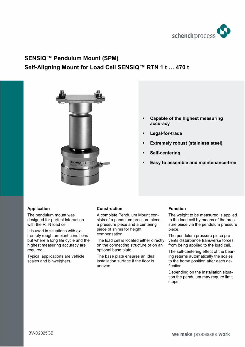
SENSiQ™ Pendulum Mount (SPM)
Self-Aligning Mount for Load Cell SENSiQ™ RTN 1 t … 470 t
Capable of the highest measuring accuracy
Legal-for-trade
Extremely robust (stainless steel)
Self-centering
Easy to assemble and maintenance-free
Application
The pendulum mount was designed for perfect interaction with the RTN load cell.
It is used in situations with ex-tremely rough ambient conditions but where a long life cycle and the highest measuring accuracy are required.
Typical applications are vehicle scales and binweighers.
Construction
A complete Pendulum Mount con-sists of a pendulum pressure piece, a pressure piece and a centering piece of shims for height compensation.
The load cell is located either directly on the connecting structure or on an optional base plate.
The base plate ensures an ideal installation surface if the floor is uneven.
Function
The weight to be measured is applied to the load cell by means of the pres-sure piece via the pendulum pressure piece.
The pendulum pressure piece pre-vents disturbance transverse forces from being applied to the load cell.
The self-centering effect of the bear-ing returns automatically the scales to the home position after each de-flection.
Depending on the installation situa-tion the pendulum may require limit stops.
BV-D2025GB
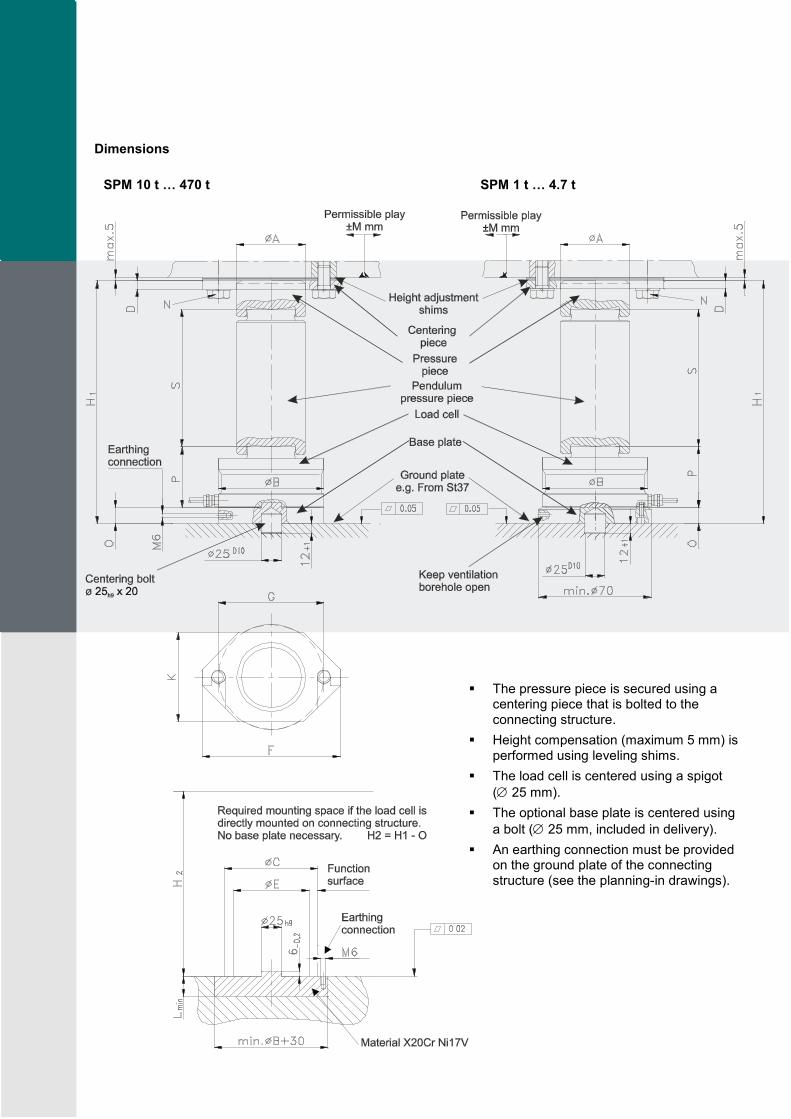
Dimensions
SPM 10 t … 470 t
SPM 1 t … 4.7 t
The pressure piece is secured using a centering piece that is bolted to the connecting structure.
Height compensation (maximum 5 mm) is performed using leveling shims.
The load cell is centered using a spigot
(∅ 25 mm).
The optional base plate is centered using
a bolt (∅ 25 mm, included in delivery).
An earthing connection must be provided on the ground plate of the connecting structure (see the planning-in drawings).
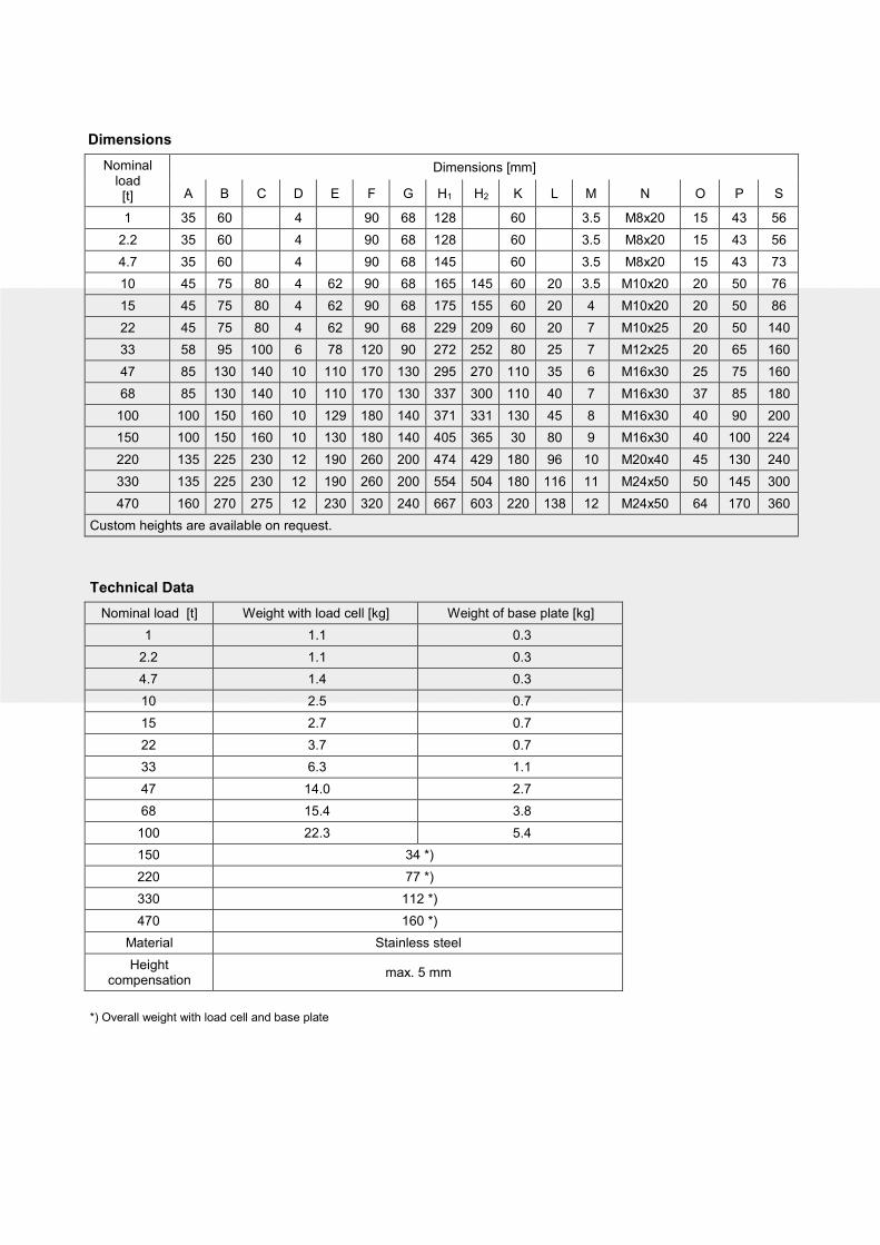
Dimensions
Nominal load [t]
Dimensions [mm]
A B C D E F G H1 H2 K L M N O P S
1 35 60 4 90 68 128 60 3.5 M8x20 15 43 56
2.2 35 60 4 90 68 128 60 3.5 M8x20 15 43 56
4.7 35 60 4 90 68 145 60 3.5 M8x20 15 43 73
10 45 75 80 4 62 90 68 165 145 60 20 3.5 M10x20 20 50 76
15 45 75 80 4 62 90 68 175 155 60 20 4 M10x20 20 50 86
22 45 75 80 4 62 90 68 229 209 60 20 7 M10x25 20 50 140
33 58 95 100 6 78 120 90 272 252 80 25 7 M12x25 20 65 160
47 85 130 140 10 110 170 130 295 270 110 35 6 M16x30 25 75 160
68 85 130 140 10 110 170 130 337 300 110 40 7 M16x30 37 85 180
100 100 150 160 10 129 180 140 371 331 130 45 8 M16x30 40 90 200
150 100 150 160 10 130 180 140 405 365 30 80 9 M16x30 40 100 224
220 135 225 230 12 190 260 200 474 429 180 96 10 M20x40 45 130 240
330 135 225 230 12 190 260 200 554 504 180 116 11 M24x50 50 145 300
470 160 270 275 12 230 320 240 667 603 220 138 12 M24x50 64 170 360
Custom heights are available on request.
Technical Data
Nominal load [t] Weight with load cell [kg] Weight of base plate [kg]
1 1.1 0.3
2.2 1.1 0.3
4.7 1.4 0.3
10 2.5 0.7
15 2.7 0.7
22 3.7 0.7
33 6.3 1.1
47 14.0 2.7
68 15.4 3.8
100 22.3 5.4
150 34 *)
220 77 *)
330 112 *)
470 160 *)
Material Stainless steel
Height compensation
max. 5 mm
*) Overall weight with load cell and base plate
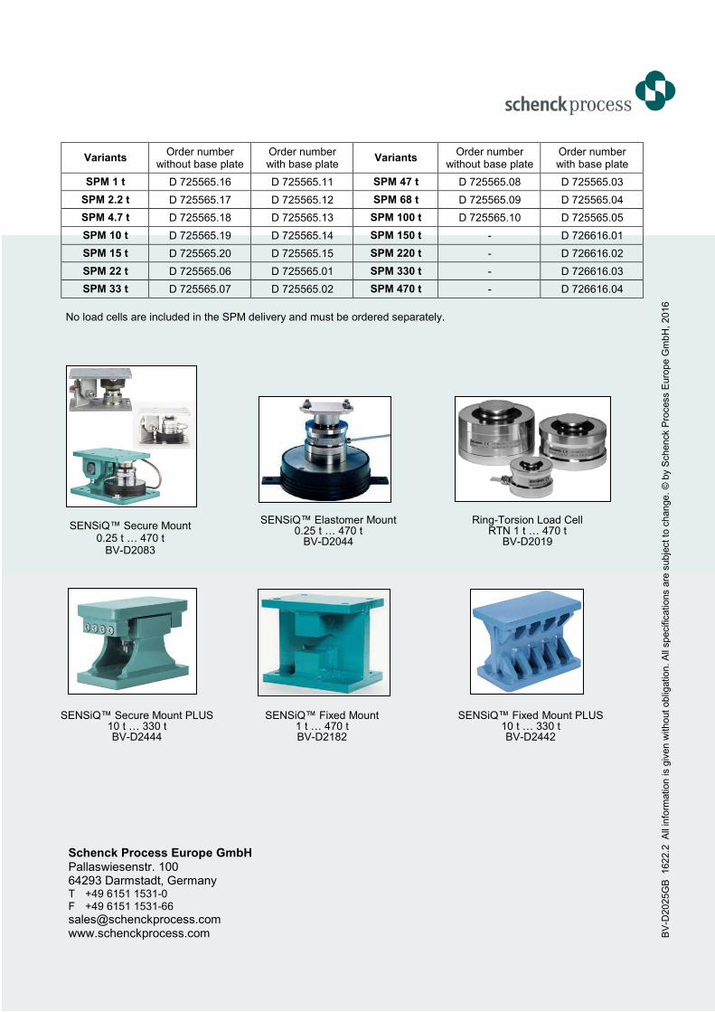
Variants Order number
without base plate Order number with base plate
Variants Order number
without base plate Order number with base plate
SPM 1 t D 725565.16 D 725565.11 SPM 47 t D 725565.08 D 725565.03
SPM 2.2 t D 725565.17 D 725565.12 SPM 68 t D 725565.09 D 725565.04
SPM 4.7 t D 725565.18 D 725565.13 SPM 100 t D 725565.10 D 725565.05
SPM 10 t D 725565.19 D 725565.14 SPM 150 t - D 726616.01
SPM 15 t D 725565.20 D 725565.15 SPM 220 t - D 726616.02
SPM 22 t D 725565.06 D 725565.01 SPM 330 t - D 726616.03
SPM 33 t D 725565.07 D 725565.02 SPM 470 t - D 726616.04
BV
-D2025G
B
1622.2
A
ll in
form
ation is g
iven w
ithout
oblig
ation. A
ll specific
ations a
re s
ubje
ct to
change.
© b
y S
chenck P
rocess E
uro
pe G
mbH
, 2016
Schenck Process Europe GmbH Pallaswiesenstr. 100 64293 Darmstadt, Germany T +49 6151 1531-0 F +49 6151 1531-66 [email protected] www.schenckprocess.com
No load cells are included in the SPM delivery and must be ordered separately.
SENSiQ™ Secure Mount PLUS 10 t … 330 t BV-D2444
SENSiQ™ Elastomer Mount 0.25 t … 470 t
BV-D2044
Ring-Torsion Load Cell RTN 1 t … 470 t
BV-D2019
SENSiQ™ Fixed Mount 1 t … 470 t BV-D2182
SENSiQ™ Fixed Mount PLUS 10 t … 330 t BV-D2442
SENSiQ™ Secure Mount 0.25 t … 470 t
BV-D2083
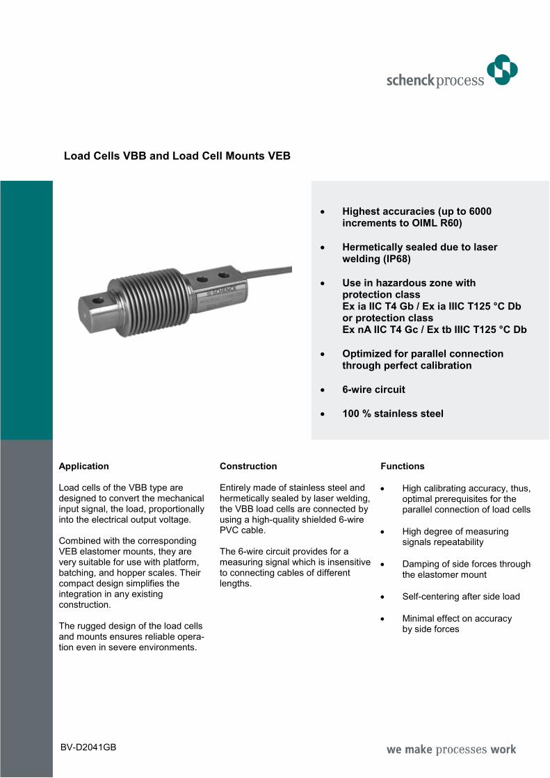
Load Cells VBB and Load Cell Mounts VEB
• Highest accuracies (up to 6000 increments to OIML R60)
• Hermetically sealed due to laser welding (IP68)
• Use in hazardous zone with protection class Ex ia IIC T4 Gb / Ex ia IIIC T125 °C Db or protection class Ex nA IIC T4 Gc / Ex tb IIIC T125 °C Db
• Optimized for parallel connection through perfect calibration
• 6-wire circuit
• 100 % stainless steel
Application Load cells of the VBB type are designed to convert the mechanical input signal, the load, proportionally into the electrical output voltage. Combined with the corresponding VEB elastomer mounts, they are very suitable for use with platform, batching, and hopper scales. Their compact design simplifies the integration in any existing construction. The rugged design of the load cells and mounts ensures reliable opera-tion even in severe environments.
Construction Entirely made of stainless steel and hermetically sealed by laser welding, the VBB load cells are connected by using a high-quality shielded 6-wire PVC cable. The 6-wire circuit provides for a measuring signal which is insensitive to connecting cables of different lengths.
Functions
• High calibrating accuracy, thus, optimal prerequisites for the parallel connection of load cells
• High degree of measuring signals repeatability
• Damping of side forces through the elastomer mount
• Self-centering after side load
• Minimal effect on accuracy by side forces
BV-D2041GB
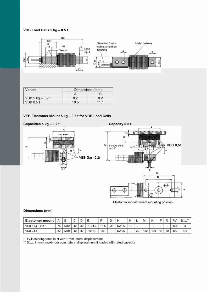
VBB Load Cells 5 kg – 0.5 t
Variant Dimensions (mm)
А В
VBB 5 kg – 0.2 t 8.2 8.2
VBB 0.5 t 10.5 11.1
VEB Elastomer Mount 5 kg – 0.5 t for VBB Load Cells Capacities 5 kg – 0.2 t Capacity 0.5 t
Elastomer mount correct mounting position
Dimensions (mm)
Elastomer mount A B C D E F G H K L M N P R FR* Smax**
VEB 5 kg – 0.2 t 75 M12 12 40 79 ±1,3 18.5 M8 SW 17 19 - - - - - 163 3
VEB 0.5 t 80 M10 10 39 26 - SW 27 - 20 120 100 9 60 400 4.5
* FR Restoring force in N with 1 mm lateral displacement ** Smax., in mm, maximum adm. lateral displacement if loaded with rated capacity
Fixation Load input
Shielded 6-wire cable, shield on housing
Metal bellows
Screws offset by 35
0
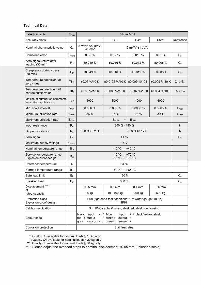
Technical Data
Rated capacity Emax 5 kg – 0.5 t
Accuracy class D1 C3* C4** C6*** Reference
Nominal characteristic value Cn 2 mV/V +20 μV/V;
-2 μV/V 2 mV/V ±1 μV/V
Combined error Fcomb 0.05 % 0.02 % 0.013 % 0.01 % Cn
Zero signal return after loading (30 min)
Fdr ±0.049 % ±0.016 % ±0.012 % ±0.008 % Cn
Creep error during stress (30 min)
Fcr ±0.049 % ±0.016 % ±0.012 % ±0.008 % Cn
Temperature coefficient of zero signal
TK0 ±0.05 %/10 K ±0.0125 %/10 K ±0.009 %/10 K ±0.009 %/10 K Cn в Вtn
Temperature coefficient of characteristic value
TKc ±0.05 %/10 K ±0.008 %/10 K ±0.007 %/10 K ±0.004 %/10 K Cn в Вtn
Maximum number of increments in certified applications
nLC 1000 3000 4000 6000
Min. scale interval vmin 0.036 % 0.009 % 0.0066 % 0.0066 % Еmax
Minimum utilisation rate Bamin 36 % 27 % 26 % 39 % Еmax
Maximum utilisation rate Bamax Bamax = Emax
Input resistance Re 350 Ω - 480 Ω tr
Output resistance Ra 356 Ω ±0.2 Ω 356 Ω ±0.12 Ω tr
Zero signal S0 ±1 % Cn
Maximum supply voltage Usmax 18 V
Nominal temperature range Btn -10 °C … +40 °C
Service temperature range Explosion-proof design
Btu -40 °C … +70 °C -30 °C … +70 °C
Reference temperature tr 23 °C
Storage temperature range Bts -50 °C … +85 °C
Safe load limit EL 150 % Cn
Breaking load ED 300 % Cn
Displacement **** at rated capacity
0.25 mm 0.3 mm 0.4 mm 0.6 mm
5 kg 10 - 100 kg 200 kg 500 kg
Protection class Explosion-proof design
IP68 (tightened test conditions: 1 m water gauge; 100 h)
IP67
Cable specification 3 m PVC cable, 6 wires, shielded, shield on housing
Colour code black: input - / blue : input + / black/yellow: shield red : output - / white : output + grey : sensor - / green : sensor +
Corrosion protection Stainless steel
*: Quality C3 available for nominal loads > 10 kg only **: Quality C4 available for nominal loads > 20 kg only ***: Quality C6 available for nominal loads > 50 kg only
****: Please adjust the overload stops to nominal displacement +0.05 mm (unloaded scale)
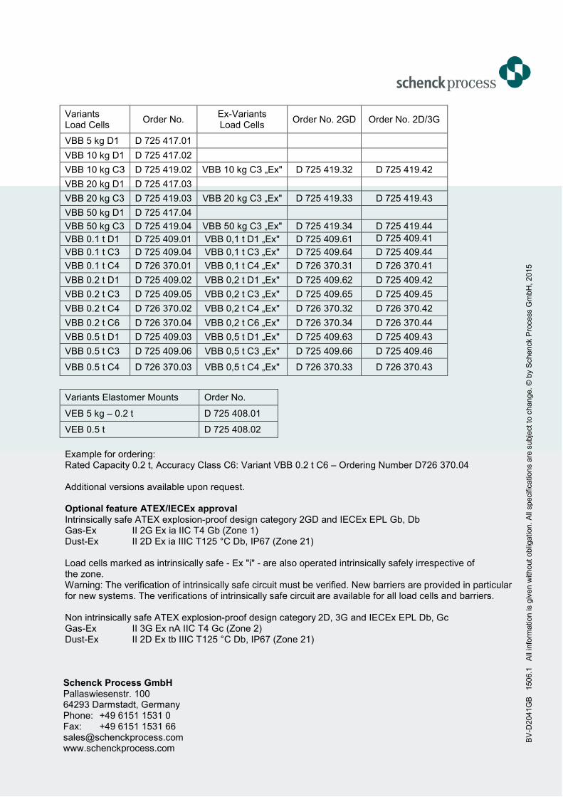
Variants Load Cells
Order No. Ex-Variants Load Cells
Order No. 2GD Order No. 2D/3G
VBB 5 kg D1 D 725 417.01
VBB 10 kg D1 D 725 417.02
VBB 10 kg СЗ D 725 419.02 VBB 10 kg СЗ „Ex" D 725 419.32 D 725 419.42
VBB 20 kg D1 D 725 417.03
VBB 20 kg C3 D 725 419.03 VBB 20 kg C3 „Ex" D 725 419.33 D 725 419.43
VBB 50 kg D1 D 725 417.04
VBB 50 kg C3 D 725 419.04 VBB 50 kg C3 „Ex" D 725 419.34 D 725 419.44
VBB 0.1 t D1 D 725 409.01 VBB 0,1 t D1 „Ex" D 725 409.61 D 725 409.41
VBB 0.1 t C3 D 725 409.04 VBB 0,1 t C3 „Ex" D 725 409.64 D 725 409.44
VBB 0.1 t C4 D 726 370.01 VBB 0,1 t C4 „Ex" D 726 370.31 D 726 370.41
VBB 0.2 t D1 D 725 409.02 VBB 0,2 t D1 „Ex" D 725 409.62 D 725 409.42
VBB 0.2 t C3 D 725 409.05 VBB 0,2 t C3 „Ex" D 725 409.65 D 725 409.45
VBB 0.2 t C4 D 726 370.02 VBB 0,2 t C4 „Ex" D 726 370.32 D 726 370.42
VBB 0.2 t C6 D 726 370.04 VBB 0,2 t C6 „Ex" D 726 370.34 D 726 370.44
VBB 0.5 t D1 D 725 409.03 VBB 0,5 t D1 „Ex" D 725 409.63 D 725 409.43
VBB 0.5 t C3 D 725 409.06 VBB 0,5 t C3 „Ex" D 725 409.66 D 725 409.46
VBB 0.5 t C4 D 726 370.03 VBB 0,5 t C4 „Ex" D 726 370.33 D 726 370.43
Variants Elastomer Mounts Order No.
VEB 5 kg – 0.2 t D 725 408.01
VEB 0.5 t D 725 408.02
Example for ordering: Rated Capacity 0.2 t, Accuracy Class C6: Variant VBB 0.2 t C6 – Ordering Number D726 370.04 Additional versions available upon request. Optional feature ATEX/IECEx approval Intrinsically safe ATEX explosion-proof design category 2GD and IECEx EPL Gb, Db Gas-Ex II 2G Ex ia IIC T4 Gb (Zone 1) Dust-Ex II 2D Ex ia IIIC T125 °C Db, IP67 (Zone 21) Load cells marked as intrinsically safe - Ex "i" - are also operated intrinsically safely irrespective of the zone. Warning: The verification of intrinsically safe circuit must be verified. New barriers are provided in particular for new systems. The verifications of intrinsically safe circuit are available for all load cells and barriers. Non intrinsically safe ATEX explosion-proof design category 2D, 3G and IECEx EPL Db, Gc Gas-Ex II 3G Ex nA IIC T4 Gc (Zone 2) Dust-Ex II 2D Ex tb IIIC T125 °C Db, IP67 (Zone 21)
Schenck Process GmbH Pallaswiesenstr. 100 64293 Darmstadt, Germany Phone: +49 6151 1531 0 Fax: +49 6151 1531 66 [email protected] www.schenckprocess.com
BV
-D2041G
B
1506.1
A
ll in
form
ation is g
iven w
ithout oblig
ation. A
ll specific
ations a
re s
ubje
ct to
change. ©
by S
chenck P
rocess G
mbH
, 2015
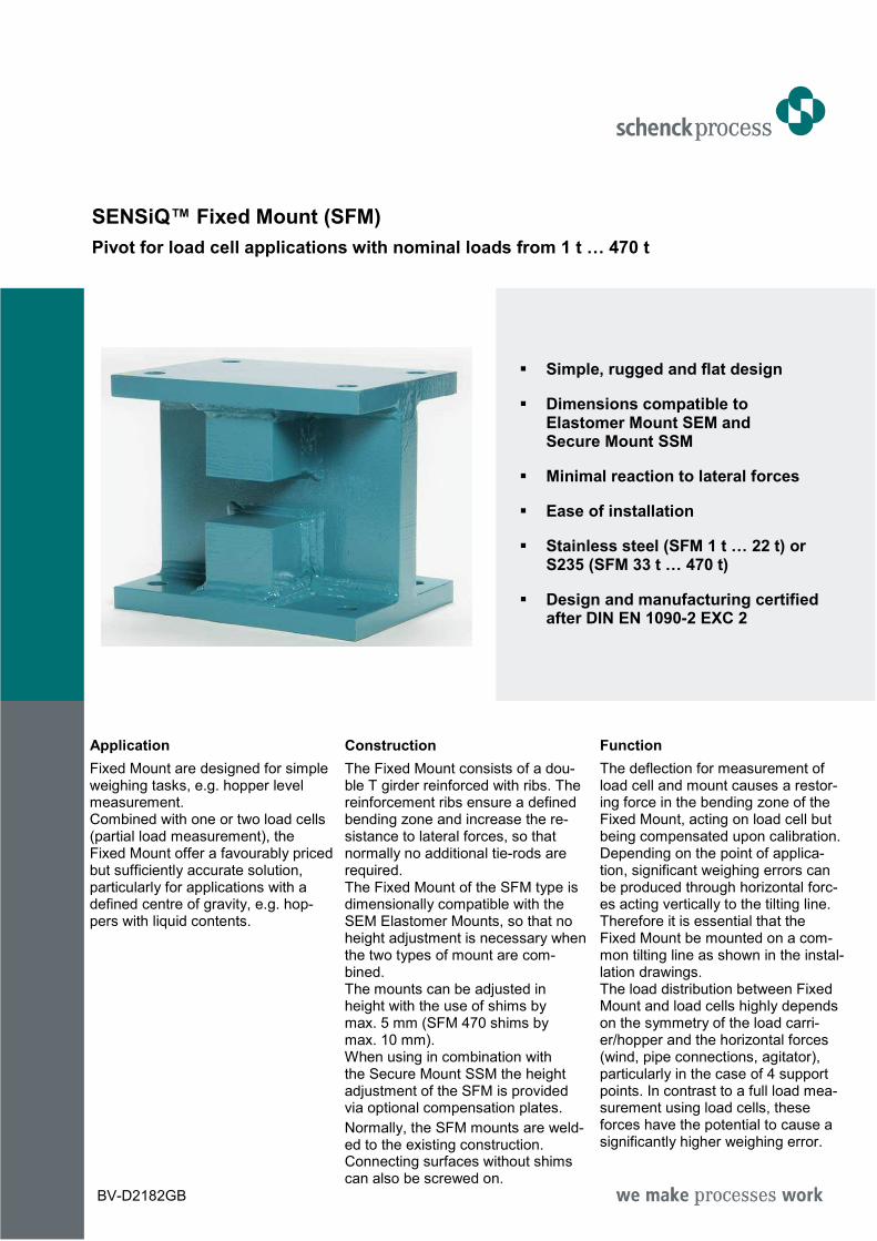
SENSiQ™ Fixed Mount (SFM)
Pivot for load cell applications with nominal loads from 1 t … 470 t
Simple, rugged and flat design
Dimensions compatible to Elastomer Mount SEM and Secure Mount SSM
Minimal reaction to lateral forces
Ease of installation
Stainless steel (SFM 1 t … 22 t) or S235 (SFM 33 t … 470 t)
Design and manufacturing certified after DIN EN 1090-2 EXC 2
Application
Fixed Mount are designed for simple weighing tasks, e.g. hopper level measurement. Combined with one or two load cells (partial load measurement), the Fixed Mount offer a favourably priced but sufficiently accurate solution, particularly for applications with a defined centre of gravity, e.g. hop-pers with liquid contents.
Construction
The Fixed Mount consists of a dou-ble T girder reinforced with ribs. The reinforcement ribs ensure a defined bending zone and increase the re-sistance to lateral forces, so that normally no additional tie-rods are required. The Fixed Mount of the SFM type is dimensionally compatible with the SEM Elastomer Mounts, so that no height adjustment is necessary when the two types of mount are com-bined. The mounts can be adjusted in height with the use of shims by max. 5 mm (SFM 470 shims by max. 10 mm). When using in combination with the Secure Mount SSM the height adjustment of the SFM is provided via optional compensation plates.
Normally, the SFM mounts are weld-ed to the existing construction. Connecting surfaces without shims can also be screwed on.
Function
The deflection for measurement of load cell and mount causes a restor-ing force in the bending zone of the Fixed Mount, acting on load cell but being compensated upon calibration. Depending on the point of applica-tion, significant weighing errors can be produced through horizontal forc-es acting vertically to the tilting line. Therefore it is essential that the Fixed Mount be mounted on a com-mon tilting line as shown in the instal-lation drawings. The load distribution between Fixed Mount and load cells highly depends on the symmetry of the load carri-er/hopper and the horizontal forces (wind, pipe connections, agitator), particularly in the case of 4 support points. In contrast to a full load mea-surement using load cells, these forces have the potential to cause a significantly higher weighing error.
BV-D2182GB
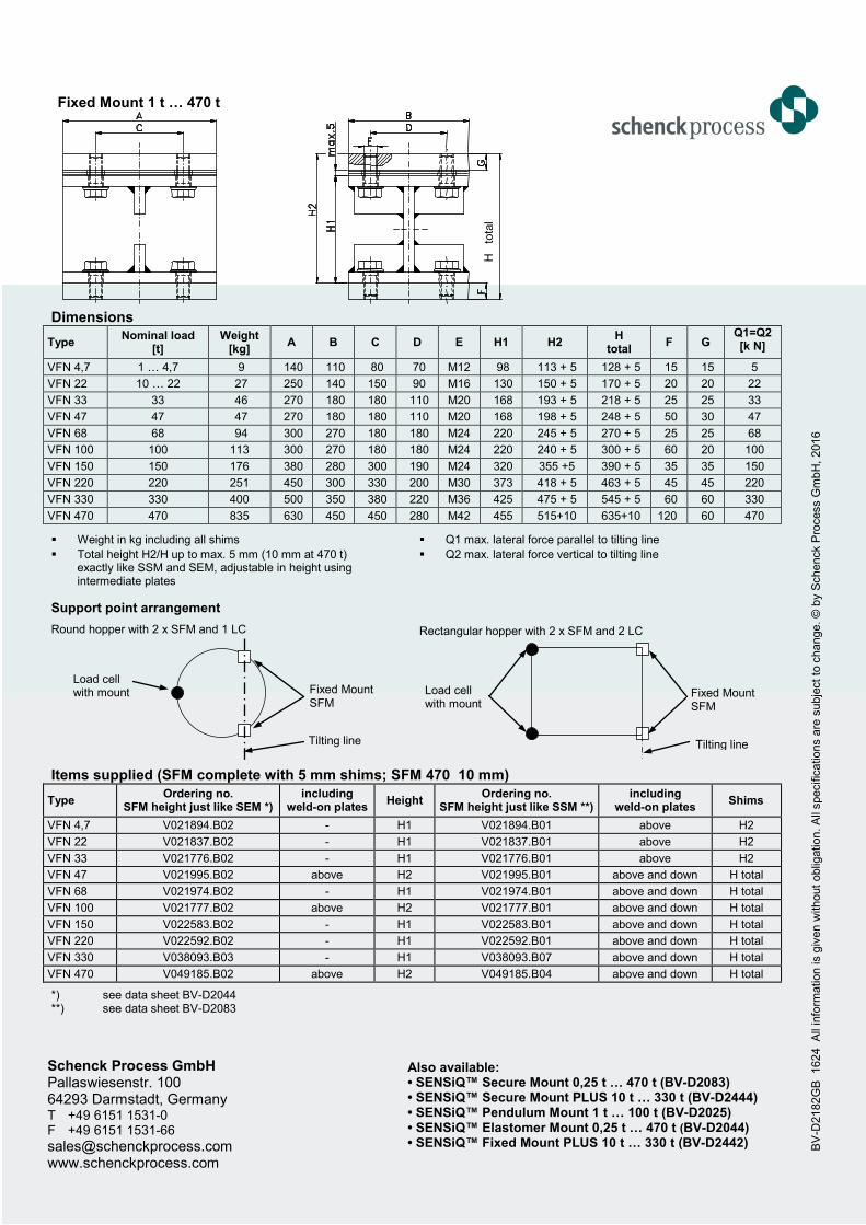
Fixed Mount 1 t … 470 t
Dimensions
Type Nominal load
[t] Weight
[kg] A B C D E H1 H2
H total
F G Q1=Q2 [k N]
VFN 4,7 1 … 4,7 9 140 110 80 70 M12 98 113 + 5 128 + 5 15 15 5
VFN 22 10 … 22 27 250 140 150 90 M16 130 150 + 5 170 + 5 20 20 22
VFN 33 33 46 270 180 180 110 M20 168 193 + 5 218 + 5 25 25 33
VFN 47 47 47 270 180 180 110 M20 168 198 + 5 248 + 5 50 30 47
VFN 68 68 94 300 270 180 180 M24 220 245 + 5 270 + 5 25 25 68
VFN 100 100 113 300 270 180 180 M24 220 240 + 5 300 + 5 60 20 100
VFN 150 150 176 380 280 300 190 M24 320 355 +5 390 + 5 35 35 150
VFN 220 220 251 450 300 330 200 M30 373 418 + 5 463 + 5 45 45 220
VFN 330 330 400 500 350 380 220 M36 425 475 + 5 545 + 5 60 60 330
VFN 470 470 835 630 450 450 280 M42 455 515+10 635+10 120 60 470
Weight in kg including all shims
Total height H2/H up to max. 5 mm (10 mm at 470 t) exactly like SSM and SEM, adjustable in height using intermediate plates
Q1 max. lateral force parallel to tilting line
Q2 max. lateral force vertical to tilting line
Support point arrangement
Round hopper with 2 x SFM and 1 LC
Rectangular hopper with 2 x SFM and 2 LC
Items supplied (SFM complete with 5 mm shims; SFM 470 10 mm)
Type Ordering no.
SFM height just like SEM *) including
weld-on plates Height
Ordering no. SFM height just like SSM **)
including weld-on plates
Shims
VFN 4,7 V021894.B02 - H1 V021894.B01 above H2
VFN 22 V021837.B02 - H1 V021837.B01 above H2
VFN 33 V021776.B02 - H1 V021776.B01 above H2
VFN 47 V021995.B02 above H2 V021995.B01 above and down H total
VFN 68 V021974.B02 - H1 V021974.B01 above and down H total
VFN 100 V021777.B02 above H2 V021777.B01 above and down H total
VFN 150 V022583.B02 - H1 V022583.B01 above and down H total
VFN 220 V022592.B02 - H1 V022592.B01 above and down H total
VFN 330 V038093.B03 - H1 V038093.B07 above and down H total
VFN 470 V049185.B02 above H2 V049185.B04 above and down H total
*) see data sheet BV-D2044 **) see data sheet BV-D2083
Schenck Process GmbH Pallaswiesenstr. 100 64293 Darmstadt, Germany T +49 6151 1531-0 F +49 6151 1531-66 [email protected] www.schenckprocess.com
BV
-D2182G
B
1624 A
ll in
form
ation is g
iven w
ithout
oblig
ation. A
ll specific
ations a
re s
ubje
ct
to c
hange. ©
by S
chenck P
rocess G
mbH
, 2016
H
tota
l
Load cell with mount
Fixed Mount SFM
Tilting line
Load cell with mount
Fixed Mount SFM
Tilting line
Also available: • SENSiQ™ Secure Mount 0,25 t … 470 t (BV-D2083) • SENSiQ™ Secure Mount PLUS 10 t … 330 t (BV-D2444) • SENSiQ™ Pendulum Mount 1 t … 100 t (BV-D2025) • SENSiQ™ Elastomer Mount 0,25 t … 470 t (BV-D2044) • SENSiQ™ Fixed Mount PLUS 10 t … 330 t (BV-D2442)
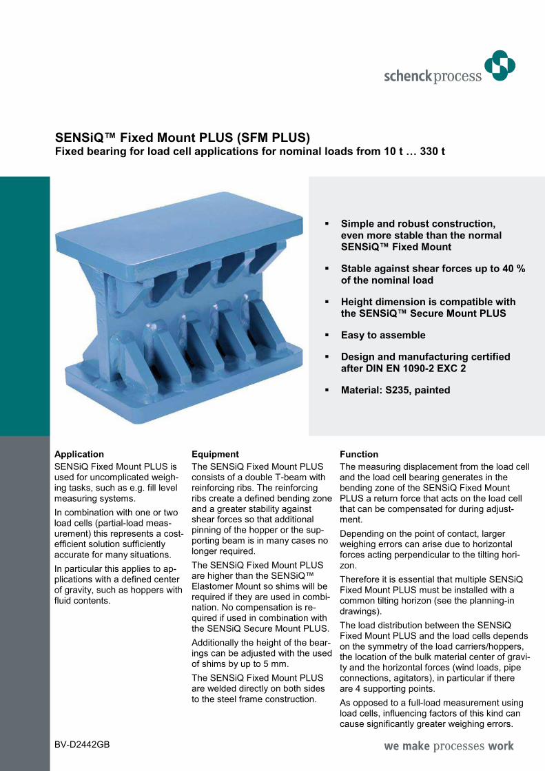
SENSiQ™ Fixed Mount PLUS (SFM PLUS) Fixed bearing for load cell applications for nominal loads from 10 t … 330 t
Simple and robust construction, even more stable than the normal SENSiQ™ Fixed Mount
Stable against shear forces up to 40 % of the nominal load
Height dimension is compatible with the SENSiQ™ Secure Mount PLUS
Easy to assemble
Design and manufacturing certified after DIN EN 1090-2 EXC 2
Material: S235, painted
Application
SENSiQ Fixed Mount PLUS is used for uncomplicated weigh-ing tasks, such as e.g. fill level measuring systems.
In combination with one or two load cells (partial-load meas-urement) this represents a cost-efficient solution sufficiently accurate for many situations.
In particular this applies to ap-plications with a defined center of gravity, such as hoppers with fluid contents.
Equipment
The SENSiQ Fixed Mount PLUS consists of a double T-beam with reinforcing ribs. The reinforcing ribs create a defined bending zone and a greater stability against shear forces so that additional pinning of the hopper or the sup-porting beam is in many cases no longer required.
The SENSiQ Fixed Mount PLUS are higher than the SENSiQ™ Elastomer Mount so shims will be required if they are used in combi-nation. No compensation is re-quired if used in combination with the SENSiQ Secure Mount PLUS.
Additionally the height of the bear-ings can be adjusted with the used of shims by up to 5 mm.
The SENSiQ Fixed Mount PLUS are welded directly on both sides to the steel frame construction.
Function
The measuring displacement from the load cell and the load cell bearing generates in the bending zone of the SENSiQ Fixed Mount PLUS a return force that acts on the load cell that can be compensated for during adjust-ment.
Depending on the point of contact, larger weighing errors can arise due to horizontal forces acting perpendicular to the tilting hori-zon.
Therefore it is essential that multiple SENSiQ Fixed Mount PLUS must be installed with a common tilting horizon (see the planning-in drawings).
The load distribution between the SENSiQ Fixed Mount PLUS and the load cells depends on the symmetry of the load carriers/hoppers, the location of the bulk material center of gravi-ty and the horizontal forces (wind loads, pipe connections, agitators), in particular if there are 4 supporting points.
As opposed to a full-load measurement using load cells, influencing factors of this kind can cause significantly greater weighing errors.
BV-D2442GB
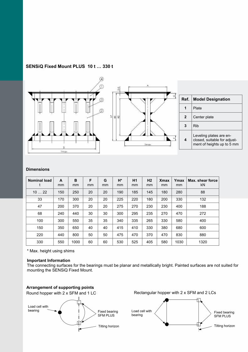
SENSiQ Fixed Mount PLUS 10 t … 330 t
Ref. Model Designation
1 Plate
2 Center plate
3 Rib
4 Leveling plates are en-closed, suitable for adjust-ment of heights up to 5 mm
Dimensions
Nominal load t
A mm
B mm
F mm
G mm
H* mm
H1 mm
H2 mm
Xmax mm
Ymax mm
Max. shear force kN
10 … 22 150 250 20 20 190 185 145 180 280 88
33 170 300 20 20 225 220 180 200 330 132
47 200 370 20 20 275 270 230 230 400 188
68 240 440 30 30 300 295 235 270 470 272
100 300 550 35 35 340 335 265 330 580 400
150 350 650 40 40 415 410 330 380 680 600
220 440 800 50 50 475 470 370 470 830 880
330 550 1000 60 60 530 525 405 580 1030 1320
* Max. height using shims Important Information The connecting surfaces for the bearings must be planar and metallically bright. Painted surfaces are not suited for mounting the SENSiQ Fixed Mount.
Arrangement of supporting points
Round hopper with 2 x SFM and 1 LC
Rectangular hopper with 2 x SFM and 2 LCs
Load cell with bearing Fixed bearing
SFM PLUS
Tilting horizon
Load cell with bearing
Fixed bearing SFM PLUS
Tilting horizon
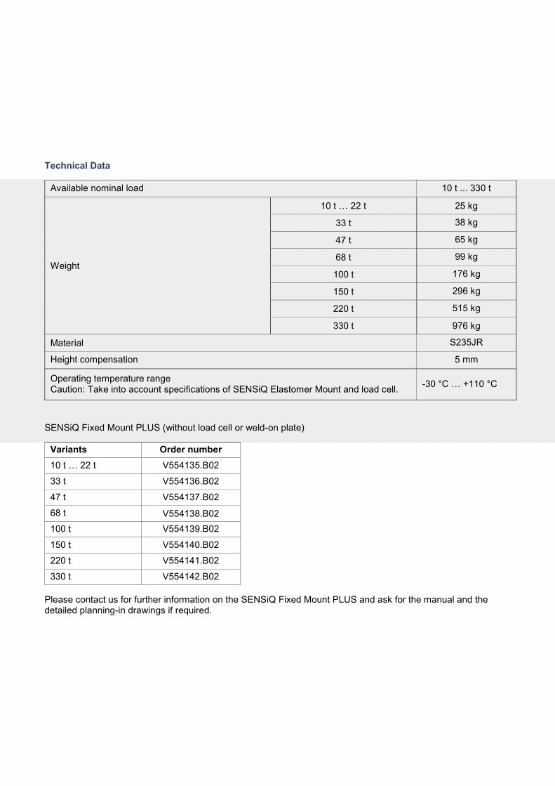
Technical Data
Available nominal load 10 t ... 330 t
Weight
10 t … 22 t 25 kg
33 t 38 kg
47 t 65 kg
68 t 99 kg
100 t 176 kg
150 t 296 kg
220 t 515 kg
330 t 976 kg
Material S235JR
Height compensation 5 mm
Operating temperature range Caution: Take into account specifications of SENSiQ Elastomer Mount and load cell.
-30 °C … +110 °C
SENSiQ Fixed Mount PLUS (without load cell or weld-on plate)
Variants Order number
10 t … 22 t V554135.B02
33 t V554136.B02
47 t V554137.B02
68 t V554138.B02
100 t V554139.B02
150 t V554140.B02
220 t V554141.B02
330 t V554142.B02
Please contact us for further information on the SENSiQ Fixed Mount PLUS and ask for the manual and the detailed planning-in drawings if required.
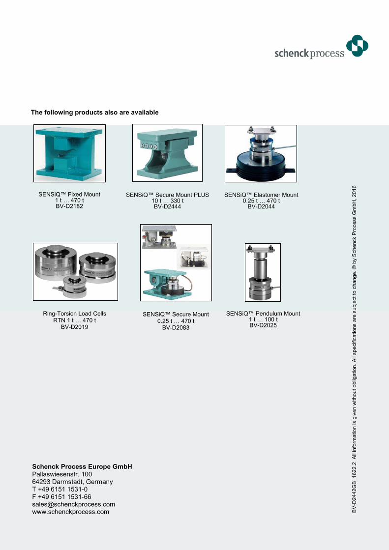
The following products also are available
Schenck Process Europe GmbH Pallaswiesenstr. 100 64293 Darmstadt, Germany T +49 6151 1531-0 F +49 6151 1531-66 [email protected] www.schenckprocess.com B
V-D
2442G
B
1622.2
A
ll in
form
ation is g
iven w
ithout
oblig
ation. A
ll specific
ations a
re s
ubje
ct to
change.
© b
y S
chenck P
rocess G
mbH
, 2016
SENSiQ™ Secure Mount PLUS 10 t … 330 t BV-D2444
SENSiQ™ Elastomer Mount 0.25 t … 470 t
BV-D2044
Ring-Torsion Load Cells RTN 1 t … 470 t
BV-D2019
SENSiQ™ Pendulum Mount 1 t … 100 t BV-D2025
SENSiQ™ Secure Mount 0.25 t … 470 t
BV-D2083
SENSiQ™ Fixed Mount 1 t … 470 t BV-D2182
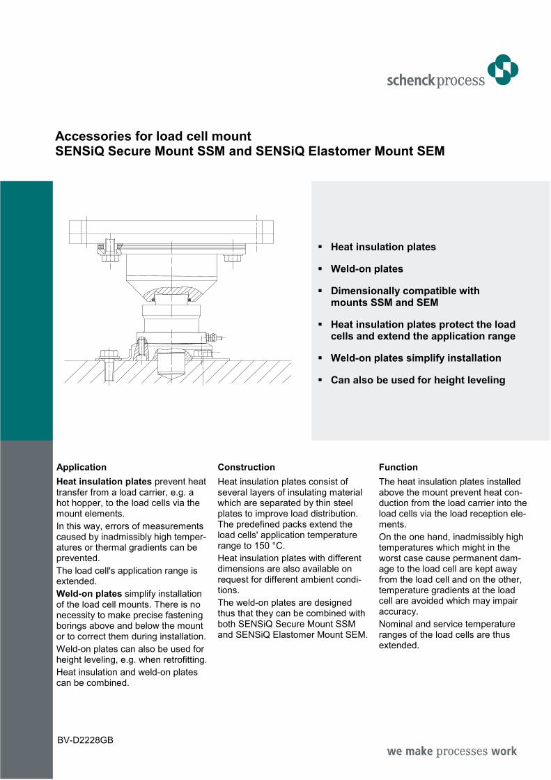
Accessories for load cell mount SENSiQ Secure Mount SSM and SENSiQ Elastomer Mount SEM
Heat insulation plates
Weld-on plates
Dimensionally compatible with mounts SSM and SEM
Heat insulation plates protect the load cells and extend the application range
Weld-on plates simplify installation
Can also be used for height leveling
Application
Heat insulation plates prevent heat transfer from a load carrier, e.g. a hot hopper, to the load cells via the mount elements.
In this way, errors of measurements caused by inadmissibly high temper-atures or thermal gradients can be prevented.
The load cell's application range is extended.
Weld-on plates simplify installation of the load cell mounts. There is no necessity to make precise fastening borings above and below the mount or to correct them during installation.
Weld-on plates can also be used for height leveling, e.g. when retrofitting.
Heat insulation and weld-on plates can be combined.
Construction
Heat insulation plates consist of several layers of insulating material which are separated by thin steel plates to improve load distribution. The predefined packs extend the load cells' application temperature range to 150 °C.
Heat insulation plates with different dimensions are also available on request for different ambient condi-tions.
The weld-on plates are designed thus that they can be combined with both SENSiQ Secure Mount SSM and SENSiQ Elastomer Mount SEM.
Function
The heat insulation plates installed above the mount prevent heat con-duction from the load carrier into the load cells via the load reception ele-ments.
On the one hand, inadmissibly high temperatures which might in the worst case cause permanent dam-age to the load cell are kept away from the load cell and on the other, temperature gradients at the load cell are avoided which may impair accuracy.
Nominal and service temperature ranges of the load cells are thus extended.
BV-D2228GB
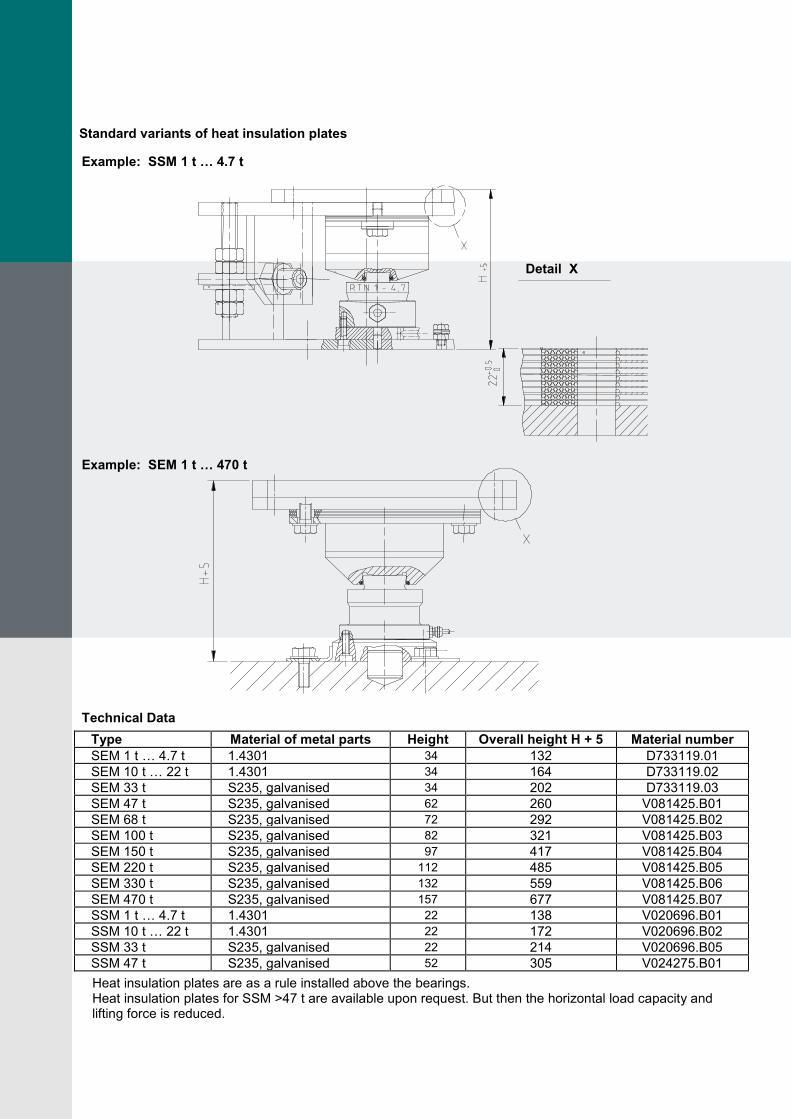
Standard variants of heat insulation plates
Example: SSM 1 t … 4.7 t
Example: SEM 1 t … 470 t
Technical Data
Type Material of metal parts Height Overall height H + 5 Material number
SEM 1 t … 4.7 t 1.4301 34 132 D733119.01
SEM 10 t … 22 t 1.4301 34 164 D733119.02
SEM 33 t S235, galvanised 34 202 D733119.03
SEM 47 t S235, galvanised 62 260 V081425.B01
SEM 68 t S235, galvanised 72 292 V081425.B02
SEM 100 t S235, galvanised 82 321 V081425.B03
SEM 150 t S235, galvanised 97 417 V081425.B04
SEM 220 t S235, galvanised 112 485 V081425.B05
SEM 330 t S235, galvanised 132 559 V081425.B06
SEM 470 t S235, galvanised 157 677 V081425.B07
SSM 1 t … 4.7 t 1.4301 22 138 V020696.B01
SSM 10 t … 22 t 1.4301 22 172 V020696.B02
SSM 33 t S235, galvanised 22 214 V020696.B05
SSM 47 t S235, galvanised 52 305 V024275.B01
Heat insulation plates are as a rule installed above the bearings. Heat insulation plates for SSM >47 t are available upon request. But then the horizontal load capacity and lifting force is reduced.
Detail X
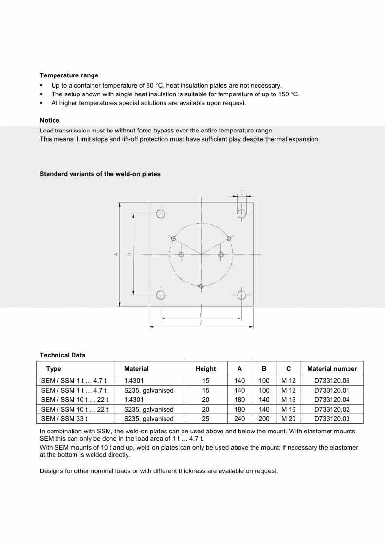
Temperature range
Up to a container temperature of 80 °C, heat insulation plates are not necessary.
The setup shown with single heat insulation is suitable for temperature of up to 150 °C.
At higher temperatures special solutions are available upon request.
Notice
Load transmission must be without force bypass over the entire temperature range.
This means: Limit stops and lift-off protection must have sufficient play despite thermal expansion.
Standard variants of the weld-on plates
Technical Data
Type Material Height A B C Material number
SEM / SSM 1 t … 4.7 t 1.4301 15 140 100 M 12 D733120.06
SEM / SSM 1 t … 4.7 t S235, galvanised 15 140 100 M 12 D733120.01
SEM / SSM 10 t … 22 t 1.4301 20 180 140 M 16 D733120.04
SEM / SSM 10 t … 22 t S235, galvanised 20 180 140 M 16 D733120.02
SEM / SSM 33 t S235, galvanised 25 240 200 M 20 D733120.03
In combination with SSM, the weld-on plates can be used above and below the mount. With elastomer mounts SEM this can only be done in the load area of 1 t … 4.7 t.
With SEM mounts of 10 t and up, weld-on plates can only be used above the mount; if necessary the elastomer at the bottom is welded directly.
Designs for other nominal loads or with different thickness are available on request.
BV
-D2228G
B
1624 A
ll in
form
ation is g
iven w
ithout
oblig
ation. A
ll specific
ations a
re s
ubje
ct
to c
hange. ©
by S
chenck P
rocess G
mbH
, 2016
Schenck Process GmbH Pallaswiesenstr. 100 64293 Darmstadt, Germany T +49 6151 1531-0 F +49 6151 1531-66 [email protected] www.schenckprocess.com
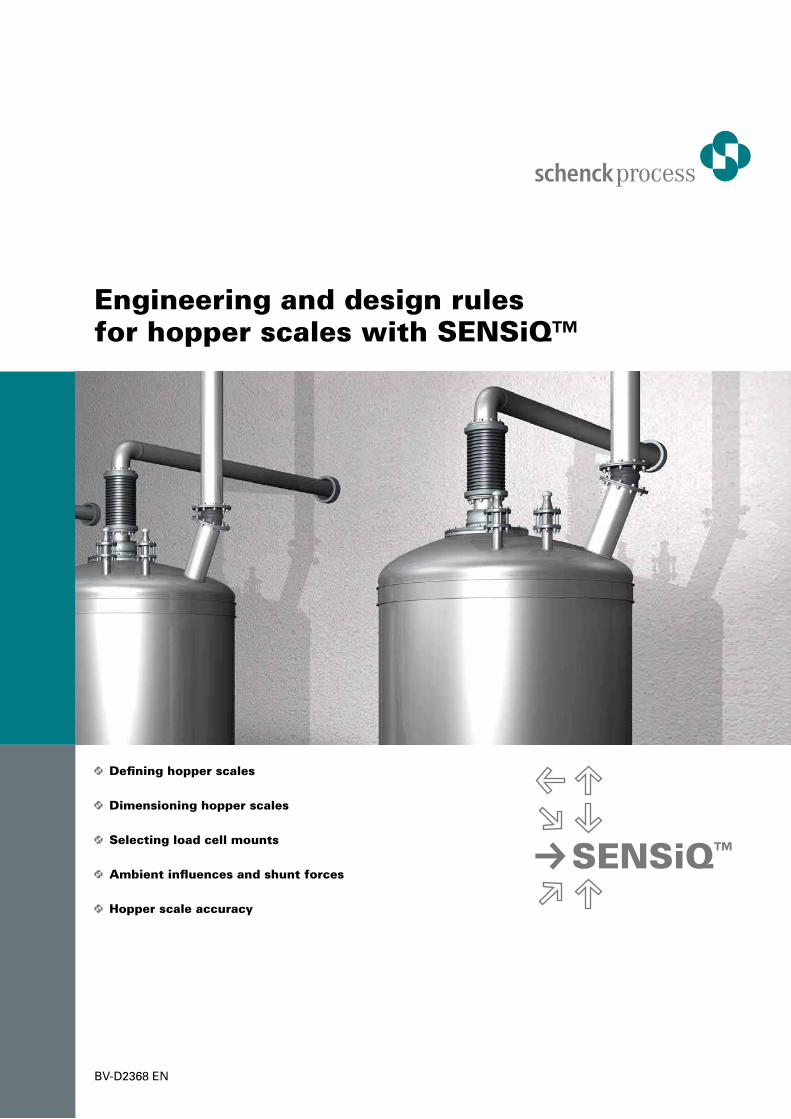
• Defining hopper scales
• Dimensioning hopper scales
• Selecting load cell mounts
• Ambient influences and shunt forces
• Hopper scale accuracy
Engineering and design rules for hopper scales with SENSiQ™
SENSiQ™
BV-D2368 EN


![Elastomer plasma polymerization Review - Characterization of … · 2018. 9. 11. · nished elastomer composites [11-15], elastomer surfaces modified by gas-phase fluorination [15-16]](https://img.pdfslide.us/doc/110x75/60bd17fb7a9618105d1a2bef/elastomer-plasma-polymerization-review-characterization-of-2018-9-11-nished.jpg)