Embed Size (px)
Citation preview
Sense Command Control
Energy Saving Sensors
Third Eye
Save Energy Today for a Better Tomorrow
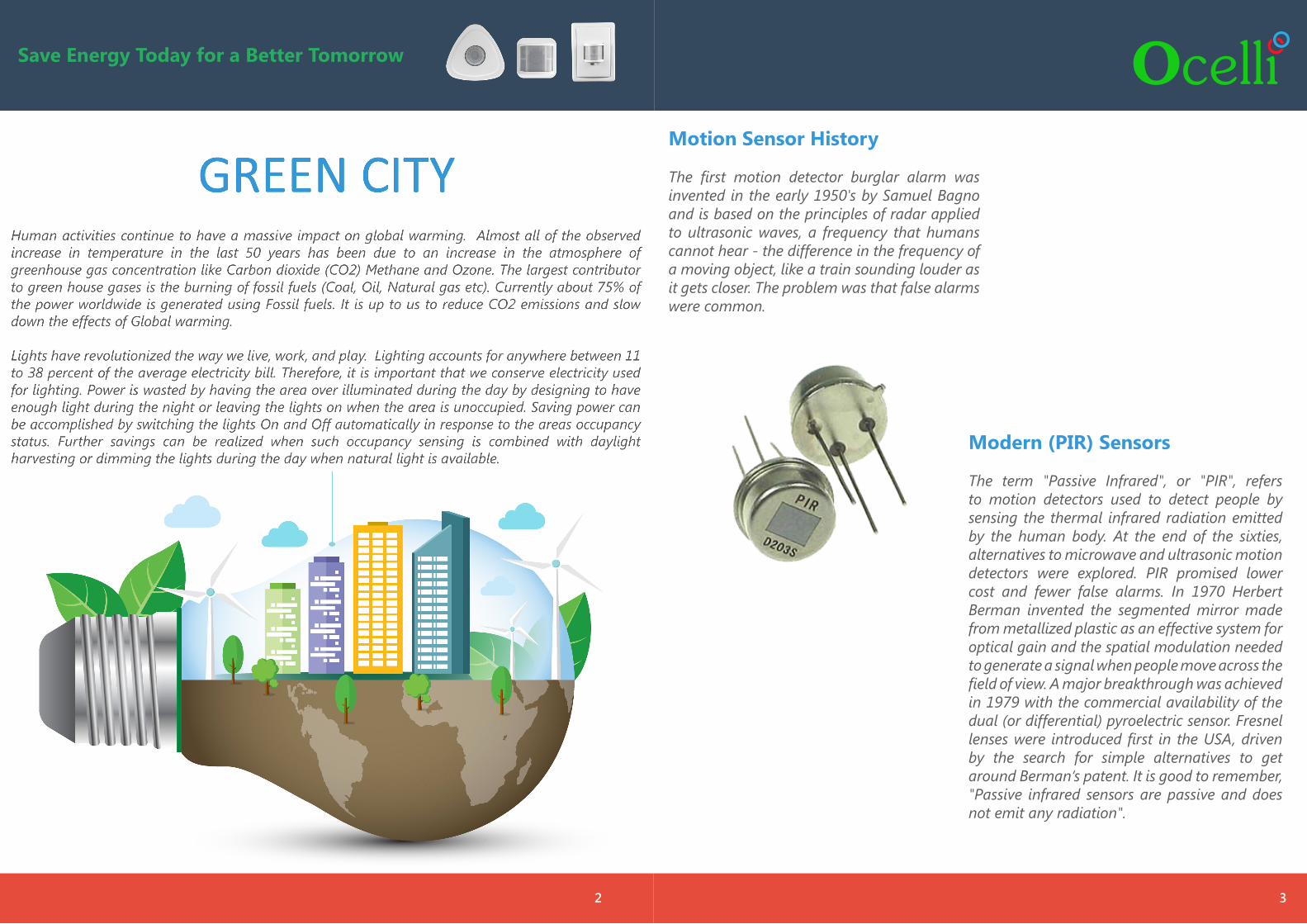
Modern (PIR) Sensors The term "Passive Infrared", or "PIR", refers to motion detectors used to detect people by sensing the thermal infrared radiation emitted by the human body. At the end of the sixties, alternatives to microwave and ultrasonic motion detectors were explored. PIR promised lower cost and fewer false alarms. In 1970 Herbert Berman invented the segmented mirror made from metallized plastic as an effective system for optical gain and the spatial modulation needed to generate a signal when people move across the field of view. A major breakthrough was achieved in 1979 with the commercial availability of the dual (or differential) pyroelectric sensor. Fresnel lenses were introduced first in the USA, driven by the search for simple alternatives to get around Berman‘s patent. It is good to remember, "Passive infrared sensors are passive and does not emit any radiation".
Motion Sensor History The first motion detector burglar alarm was invented in the early 1950's by Samuel Bagno and is based on the principles of radar applied to ultrasonic waves, a frequency that humans cannot hear - the difference in the frequency of a moving object, like a train sounding louder as it gets closer. The problem was that false alarms were common.
2
Save Energy Today for a Better Tomorrow
3
4
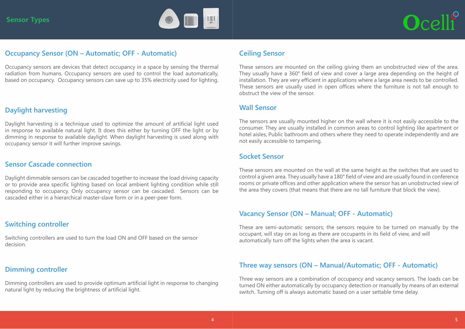
Sensor Types
5
Occupancy Sensor (ON – Automatic; OFF - Automatic)
Occupancy sensors are devices that detect occupancy in a space by sensing the thermal radiation from humans. Occupancy sensors are used to control the load automatically, based on occupancy. Occupancy sensors can save up to 35% electricity used for lighting.
Daylight harvesting
Daylight harvesting is a technique used to optimize the amount of artificial light used in response to available natural light. It does this either by turning OFF the light or by dimming in response to available daylight. When daylight harvesting is used along with occupancy sensor it will further improve savings.
Sensor Cascade connection
Daylight dimmable sensors can be cascaded together to increase the load driving capacity or to provide area specific lighting based on local ambient lighting condition while still responding to occupancy. Only occupancy sensor can be cascaded. Sensors can be cascaded either in a hierarchical master-slave form or in a peer-peer form.
Switching controller
Switching controllers are used to turn the load ON and OFF based on the sensor decision.
Dimming controller
Dimming controllers are used to provide optimum artificial light in response to changing natural light by reducing the brightness of artificial light.
Ceiling Sensor
These sensors are mounted on the ceiling giving them an unobstructed view of the area. They usually have a 360° field of view and cover a large area depending on the height of installation. They are very efficient in applications where a large area needs to be controlled. These sensors are usually used in open offices where the furniture is not tall enough to obstruct the view of the sensor.
Wall Sensor
The sensors are usually mounted higher on the wall where it is not easily accessible to the consumer. They are usually installed in common areas to control lighting like apartment or hotel aisles, Public bathroom and others where they need to operate independently and are not easily accessible to tampering.
Socket Sensor
These sensors are mounted on the wall at the same height as the switches that are used to control a given area. They usually have a 180° field of view and are usually found in conference rooms or private offices and other application where the sensor has an unobstructed view of the area they covers (that means that there are no tall furniture that block the view).
Vacancy Sensor (ON – Manual; OFF - Automatic)
These are semi-automatic sensors; the sensors require to be turned on manually by the occupant, will stay on as long as there are occupants in its field of view, and willautomatically turn off the lights when the area is vacant.
Three way sensors (ON – Manual/Automatic; OFF - Automatic)
Three way sensors are a combination of occupancy and vacancy sensors. The loads can be turned ON either automatically by occupancy detection or manually by means of an external switch. Turning off is always automatic based on a user settable time delay.
Lant
ern
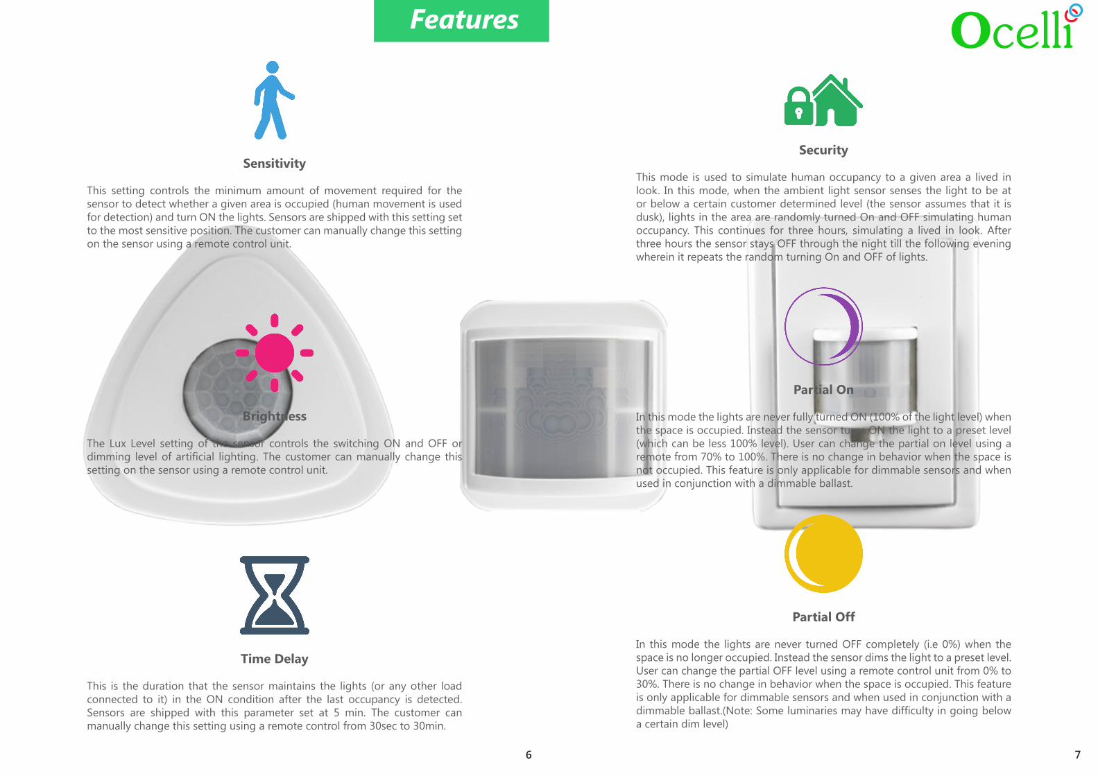
Security
This mode is used to simulate human occupancy to a given area a lived in look. In this mode, when the ambient light sensor senses the light to be at or below a certain customer determined level (the sensor assumes that it is dusk), lights in the area are randomly turned On and OFF simulating human occupancy. This continues for three hours, simulating a lived in look. After three hours the sensor stays OFF through the night till the following evening wherein it repeats the random turning On and OFF of lights.
Partial On
In this mode the lights are never fully turned ON (100% of the light level) when the space is occupied. Instead the sensor turns ON the light to a preset level (which can be less 100% level). User can change the partial on level using a remote from 70% to 100%. There is no change in behavior when the space is not occupied. This feature is only applicable for dimmable sensors and when used in conjunction with a dimmable ballast.
Partial Off
In this mode the lights are never turned OFF completely (i.e 0%) when the space is no longer occupied. Instead the sensor dims the light to a preset level. User can change the partial OFF level using a remote control unit from 0% to 30%. There is no change in behavior when the space is occupied. This feature is only applicable for dimmable sensors and when used in conjunction with a dimmable ballast.(Note: Some luminaries may have difficulty in going below a certain dim level)
Sensitivity
This setting controls the minimum amount of movement required for the sensor to detect whether a given area is occupied (human movement is used for detection) and turn ON the lights. Sensors are shipped with this setting set to the most sensitive position. The customer can manually change this setting on the sensor using a remote control unit.
Brightness
The Lux Level setting of the sensor controls the switching ON and OFF or dimming level of artificial lighting. The customer can manually change this setting on the sensor using a remote control unit.
Time Delay
This is the duration that the sensor maintains the lights (or any other load connected to it) in the ON condition after the last occupancy is detected. Sensors are shipped with this parameter set at 5 min. The customer can manually change this setting using a remote control from 30sec to 30min.
Features
6 7
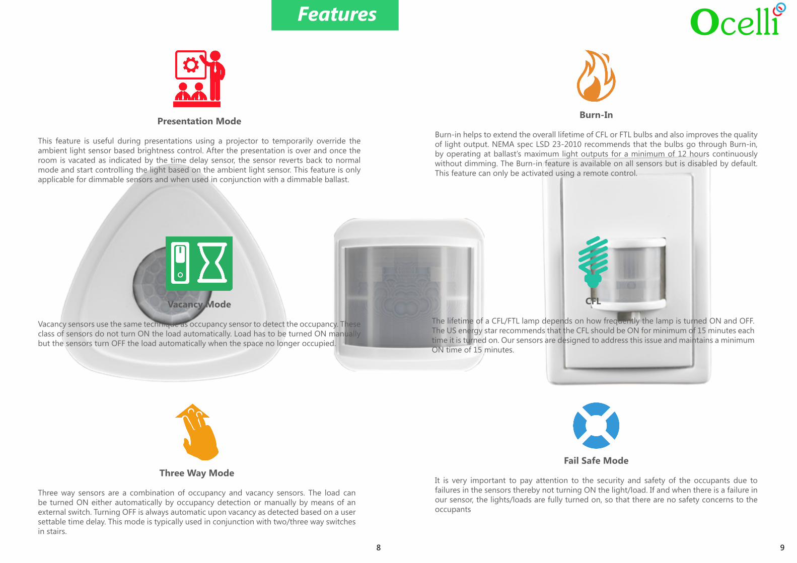
Presentation Mode
This feature is useful during presentations using a projector to temporarily override the ambient light sensor based brightness control. After the presentation is over and once the room is vacated as indicated by the time delay sensor, the sensor reverts back to normal mode and start controlling the light based on the ambient light sensor. This feature is only applicable for dimmable sensors and when used in conjunction with a dimmable ballast.
Vacancy Mode
Vacancy sensors use the same technique as occupancy sensor to detect the occupancy. These class of sensors do not turn ON the load automatically. Load has to be turned ON manually but the sensors turn OFF the load automatically when the space no longer occupied.
Three Way Mode
Three way sensors are a combination of occupancy and vacancy sensors. The load can be turned ON either automatically by occupancy detection or manually by means of an external switch. Turning OFF is always automatic upon vacancy as detected based on a user settable time delay. This mode is typically used in conjunction with two/three way switches in stairs.
Features
Burn-In
Burn-in helps to extend the overall lifetime of CFL or FTL bulbs and also improves the quality of light output. NEMA spec LSD 23-2010 recommends that the bulbs go through Burn-in, by operating at ballast’s maximum light outputs for a minimum of 12 hours continuously without dimming. The Burn-in feature is available on all sensors but is disabled by default. This feature can only be activated using a remote control.
CFL
The lifetime of a CFL/FTL lamp depends on how frequently the lamp is turned ON and OFF. The US energy star recommends that the CFL should be ON for minimum of 15 minutes each time it is turned on. Our sensors are designed to address this issue and maintains a minimum ON time of 15 minutes.
Fail Safe Mode
It is very important to pay attention to the security and safety of the occupants due to failures in the sensors thereby not turning ON the light/load. If and when there is a failure in our sensor, the lights/loads are fully turned on, so that there are no safety concerns to the occupants
98
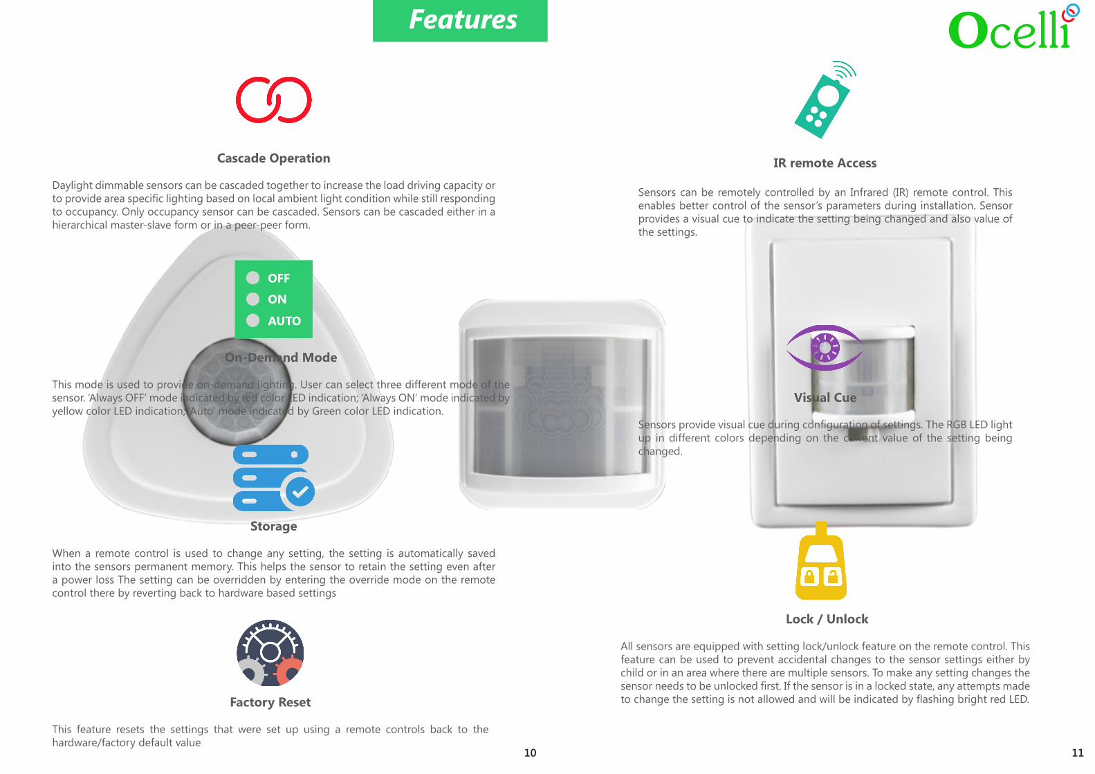
IR remote Access
Sensors can be remotely controlled by an Infrared (IR) remote control. This enables better control of the sensor’s parameters during installation. Sensor provides a visual cue to indicate the setting being changed and also value of the settings.
Visual Cue
Sensors provide visual cue during configuration of settings. The RGB LED light up in different colors depending on the current value of the setting being changed.
Storage
When a remote control is used to change any setting, the setting is automatically saved into the sensors permanent memory. This helps the sensor to retain the setting even after a power loss The setting can be overridden by entering the override mode on the remote control there by reverting back to hardware based settings
Features
Cascade Operation
Daylight dimmable sensors can be cascaded together to increase the load driving capacity or to provide area specific lighting based on local ambient light condition while still responding to occupancy. Only occupancy sensor can be cascaded. Sensors can be cascaded either in a hierarchical master-slave form or in a peer-peer form.
On-Demand Mode
This mode is used to provide on-demand lighting. User can select three different mode of the sensor. ‘Always OFF’ mode indicated by red color LED indication; ‘Always ON’ mode indicated by yellow color LED indication; ‘Auto’ mode indicated by Green color LED indication.
OFF
ON
AUTO
Lock / Unlock
All sensors are equipped with setting lock/unlock feature on the remote control. This feature can be used to prevent accidental changes to the sensor settings either by child or in an area where there are multiple sensors. To make any setting changes the sensor needs to be unlocked first. If the sensor is in a locked state, any attempts made to change the setting is not allowed and will be indicated by flashing bright red LED.
10 11
Factory Reset
This feature resets the settings that were set up using a remote controls back to the hardware/factory default value
Future Proof
Sensors are firmware upgradable in the field with a special accessory. This makes the sensor future proof and purchase decision easier for the user.
Features
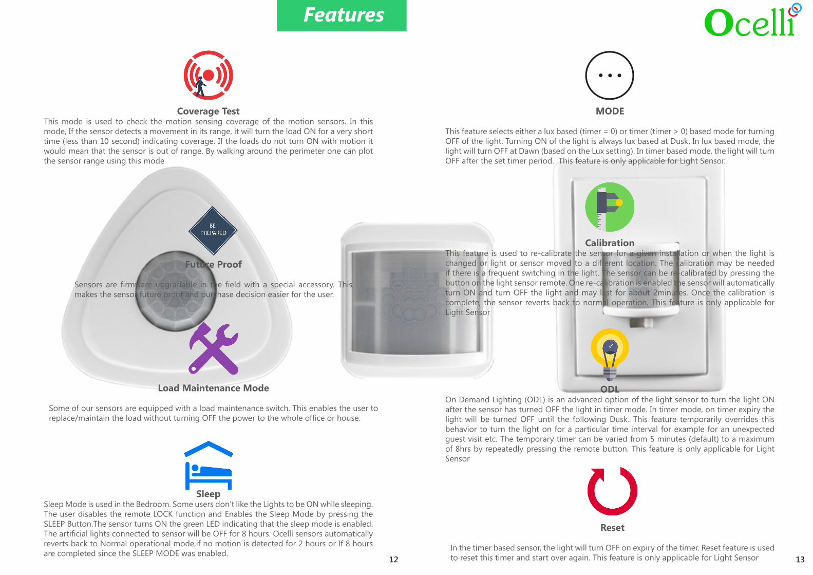
Coverage TestThis mode is used to check the motion sensing coverage of the motion sensors. In this mode, If the sensor detects a movement in its range, it will turn the load ON for a very short time (less than 10 second) indicating coverage. If the loads do not turn ON with motion it would mean that the sensor is out of range. By walking around the perimeter one can plot the sensor range using this mode
12 13
MODE
This feature selects either a lux based (timer = 0) or timer (timer > 0) based mode for turning OFF of the light. Turning ON of the light is always lux based at Dusk. In lux based mode, the light will turn OFF at Dawn (based on the Lux setting). In timer based mode, the light will turn OFF after the set timer period. This feature is only applicable for Light Sensor.
CalibrationThis feature is used to re-calibrate the sensor for a given installation or when the light is changed or light or sensor moved to a different location. The calibration may be needed if there is a frequent switching in the light. The sensor can be re-calibrated by pressing the button on the light sensor remote. One re-calibration is enabled the sensor will automatically turn ON and turn OFF the light and may last for about 2minutes. Once the calibration is complete, the sensor reverts back to normal operation. This feature is only applicable for Light Sensor
ODLOn Demand Lighting (ODL) is an advanced option of the light sensor to turn the light ON after the sensor has turned OFF the light in timer mode. In timer mode, on timer expiry the light will be turned OFF until the following Dusk. This feature temporarily overrides this behavior to turn the light on for a particular time interval for example for an unexpected guest visit etc. The temporary timer can be varied from 5 minutes (default) to a maximum of 8hrs by repeatedly pressing the remote button. This feature is only applicable for Light Sensor
Reset
In the timer based sensor, the light will turn OFF on expiry of the timer. Reset feature is used to reset this timer and start over again. This feature is only applicable for Light Sensor
SleepSleep Mode is used in the Bedroom. Some users don’t like the Lights to be ON while sleeping.The user disables the remote LOCK function and Enables the Sleep Mode by pressing the SLEEP Button.The sensor turns ON the green LED indicating that the sleep mode is enabled. The artificial lights connected to sensor will be OFF for 8 hours. Ocelli sensors automatically reverts back to Normal operational mode,if no motion is detected for 2 hours or If 8 hours are completed since the SLEEP MODE was enabled.
Load Maintenance Mode
Some of our sensors are equipped with a load maintenance switch. This enables the user to replace/maintain the load without turning OFF the power to the whole office or house.
Specifications
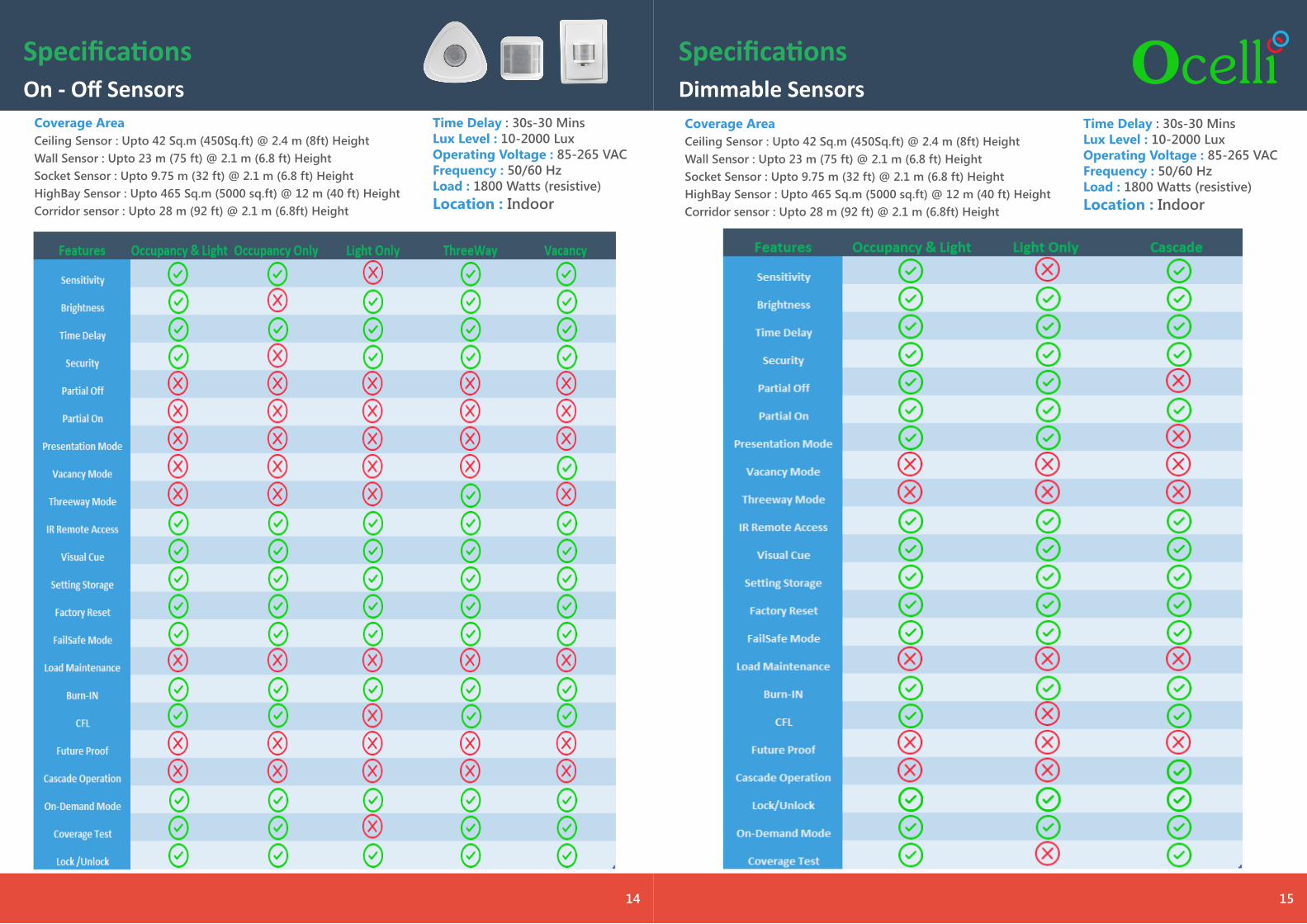
Coverage AreaCeiling Sensor : Upto 42 Sq.m (450Sq.ft) @ 2.4 m (8ft) Height Wall Sensor : Upto 23 m (75 ft) @ 2.1 m (6.8 ft) HeightSocket Sensor : Upto 9.75 m (32 ft) @ 2.1 m (6.8 ft) HeightHighBay Sensor : Upto 465 Sq.m (5000 sq.ft) @ 12 m (40 ft) HeightCorridor sensor : Upto 28 m (92 ft) @ 2.1 m (6.8ft) Height
Time Delay : 30s-30 MinsLux Level : 10-2000 LuxOperating Voltage : 85-265 VAC Frequency : 50/60 HzLoad : 1800 Watts (resistive)Location : Indoor
On - Off Sensors
14
SpecificationsDimmable Sensors
15
Coverage AreaCeiling Sensor : Upto 42 Sq.m (450Sq.ft) @ 2.4 m (8ft) Height Wall Sensor : Upto 23 m (75 ft) @ 2.1 m (6.8 ft) HeightSocket Sensor : Upto 9.75 m (32 ft) @ 2.1 m (6.8 ft) HeightHighBay Sensor : Upto 465 Sq.m (5000 sq.ft) @ 12 m (40 ft) HeightCorridor sensor : Upto 28 m (92 ft) @ 2.1 m (6.8ft) Height
Time Delay : 30s-30 MinsLux Level : 10-2000 LuxOperating Voltage : 85-265 VAC Frequency : 50/60 HzLoad : 1800 Watts (resistive)Location : Indoor
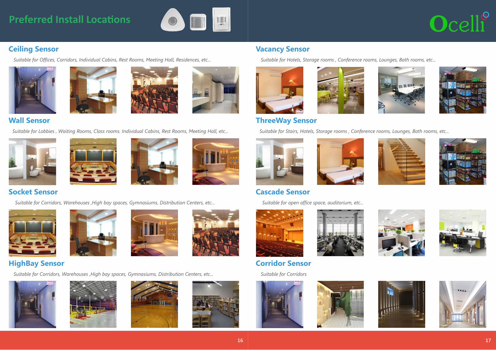
Preferred Install Locations
Ceiling SensorSuitable for Offices, Corridors, Individual Cabins, Rest Rooms, Meeting Hall, Residences, etc...
Wall SensorSuitable for Lobbies , Waiting Rooms, Class rooms. Individual Cabins, Rest Rooms, Meeting Hall, etc...
Socket SensorSuitable for Corridors, Warehouses ,High bay spaces, Gymnasiums, Distribution Centers, etc...
HighBay SensorSuitable for Corridors, Warehouses ,High bay spaces, Gymnasiums, Distribution Centers, etc...
16
Vacancy SensorSuitable for Hotels, Storage rooms , Conference rooms, Lounges, Bath rooms, etc...
ThreeWay SensorSuitable for Stairs, Hotels, Storage rooms , Conference rooms, Lounges, Bath rooms, etc...
Cascade SensorSuitable for open office space, auditorium, etc...
Corridor SensorSuitable for Corridors
17
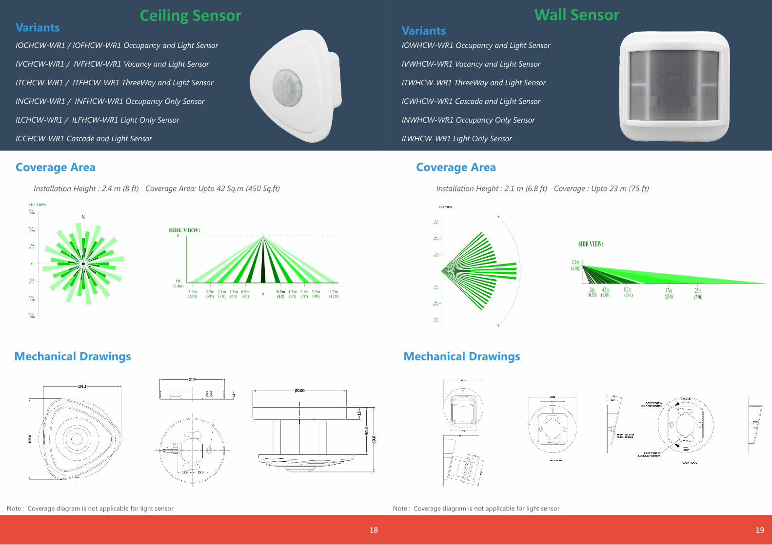
Coverage Area
Installation Height : 2.4 m (8 ft) Coverage Area: Upto 42 Sq.m (450 Sq.ft)
Mechanical Drawings
Note : Coverage diagram is not applicable for light sensor
Ceiling SensorIOCHCW-WR1 / IOFHCW-WR1 Occupancy and Light Sensor
IVCHCW-WR1 / IVFHCW-WR1 Vacancy and Light Sensor
ITCHCW-WR1 / ITFHCW-WR1 ThreeWay and Light Sensor
INCHCW-WR1 / INFHCW-WR1 Occupancy Only Sensor
ILCHCW-WR1 / ILFHCW-WR1 Light Only Sensor
ICCHCW-WR1 Cascade and Light Sensor
Variants
18
Coverage Area
Installation Height : 2.1 m (6.8 ft) Coverage : Upto 23 m (75 ft)
Mechanical Drawings
Note : Coverage diagram is not applicable for light sensor
Wall Sensor
IOWHCW-WR1 Occupancy and Light Sensor
IVWHCW-WR1 Vacancy and Light Sensor
ITWHCW-WR1 ThreeWay and Light Sensor
ICWHCW-WR1 Cascade and Light Sensor
INWHCW-WR1 Occupancy Only Sensor
ILWHCW-WR1 Light Only Sensor
Variants
19
Coverage Area
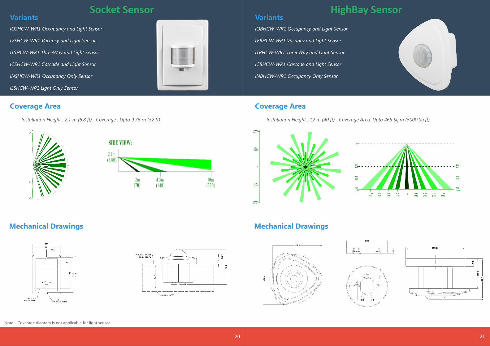
Installation Height : 2.1 m (6.8 ft) Coverage : Upto 9.75 m (32 ft)
Mechanical Drawings
Note : Coverage diagram is not applicable for light sensor
Socket SensorIOSHCW-WR1 Occupancy and Light Sensor
IVSHCW-WR1 Vacancy and Light Sensor
ITSHCW-WR1 ThreeWay and Light Sensor
ICSHCW-WR1 Cascade and Light Sensor
INSHCW-WR1 Occupancy Only Sensor
ILSHCW-WR1 Light Only Sensor
Variants
20
Coverage Area
Installation Height : 12 m (40 ft) Coverage Area: Upto 465 Sq.m (5000 Sq.ft)
Mechanical Drawings
HighBay SensorIOBHCW-WR1 Occupancy and Light Sensor
IVBHCW-WR1 Vacancy and Light Sensor
ITBHCW-WR1 ThreeWay and Light Sensor
ICBHCW-WR1 Cascade and Light Sensor
INBHCW-WR1 Occupancy Only Sensor
Variants
21
Coverage Area
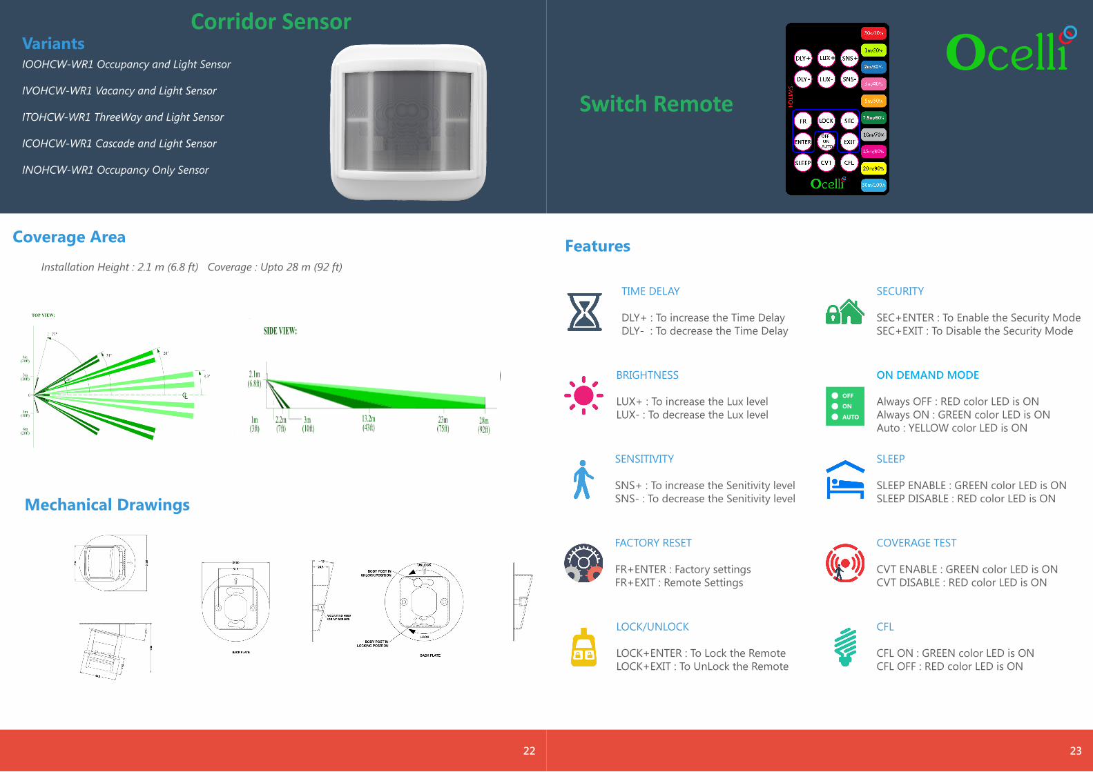
Installation Height : 2.1 m (6.8 ft) Coverage : Upto 28 m (92 ft)
Mechanical Drawings
Corridor SensorIOOHCW-WR1 Occupancy and Light Sensor
IVOHCW-WR1 Vacancy and Light Sensor
ITOHCW-WR1 ThreeWay and Light Sensor
ICOHCW-WR1 Cascade and Light Sensor
INOHCW-WR1 Occupancy Only Sensor
Variants
22
Features
23
TIME DELAY
DLY+ : To increase the Time DelayDLY- : To decrease the Time Delay
BRIGHTNESS
LUX+ : To increase the Lux levelLUX- : To decrease the Lux level
SENSITIVITY
SNS+ : To increase the Senitivity levelSNS- : To decrease the Senitivity level
FACTORY RESET
FR+ENTER : Factory settingsFR+EXIT : Remote Settings
LOCK/UNLOCK
LOCK+ENTER : To Lock the RemoteLOCK+EXIT : To UnLock the Remote
SECURITY
SEC+ENTER : To Enable the Security ModeSEC+EXIT : To Disable the Security Mode
SLEEP
SLEEP ENABLE : GREEN color LED is ON SLEEP DISABLE : RED color LED is ON
COVERAGE TEST
CVT ENABLE : GREEN color LED is ON CVT DISABLE : RED color LED is ON
OFF
ON
AUTO
ON DEMAND MODE
Always OFF : RED color LED is ON Always ON : GREEN color LED is ON Auto : YELLOW color LED is ON
CFL
CFL ON : GREEN color LED is ON CFL OFF : RED color LED is ON
Switch Remote
Features
24
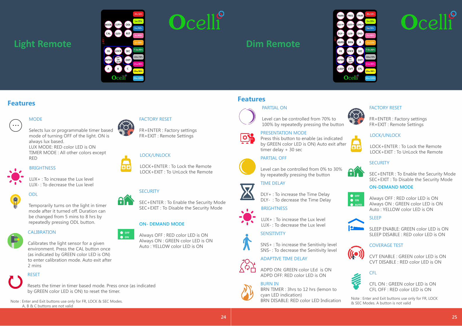
MODE
Selects lux or programmable timer based mode of turning OFF of the light. ON is always lux based.LUX MODE: RED color LED is ONTIMER MODE : All other colors except RED
BRIGHTNESS
LUX+ : To increase the Lux levelLUX- : To decrease the Lux level
ODL
Temporarily turns on the light in timer mode after it turned off. Duration can be changed from 5 mins to 8 hrs by repeatedly pressing ODL button.
FACTORY RESET
FR+ENTER : Factory settingsFR+EXIT : Remote Settings
LOCK/UNLOCK
LOCK+ENTER : To Lock the RemoteLOCK+EXIT : To UnLock the Remote
SECURITY
SEC+ENTER : To Enable the Security ModeSEC+EXIT : To Disable the Security Mode
CALIBRATION
Calibrates the light sensor for a given environment. Press the CAL button once (as indicated by GREEN color LED is ON) to enter calibration mode. Auto exit after 2 mins
RESET
Resets the timer in timer based mode. Press once (as indicated by GREEN color LED is ON) to reset the timer.
OFF
ON
AUTO
ON- DEMAND MODE
Always OFF : RED color LED is ON Always ON : GREEN color LED is ON Auto : YELLOW color LED is ON
Note : Enter and Exit buttons use only for FR, LOCK & SEC Modes. A, B & C buttons are not valid
25
Features
TIME DELAY
DLY+ : To increase the Time DelayDLY- : To decrease the Time Delay
BRIGHTNESS
LUX+ : To increase the Lux levelLUX- : To decrease the Lux level
SENSITIVITY
SNS+ : To increase the Senitivity levelSNS- : To decrease the Senitivity level
FACTORY RESET
FR+ENTER : Factory settingsFR+EXIT : Remote Settings
LOCK/UNLOCK
LOCK+ENTER : To Lock the RemoteLOCK+EXIT : To UnLock the Remote
SECURITY
SEC+ENTER : To Enable the Security ModeSEC+EXIT : To Disable the Security Mode
SLEEP
SLEEP ENABLE: GREEN color LED is ON SLEEP DISABLE : RED color LED is ON
COVERAGE TEST
CVT ENABLE : GREEN color LED is ON CVT DISABLE : RED color LED is ON
OFF
ON
AUTO
ON-DEMAND MODE
Always OFF : RED color LED is ON Always ON : GREEN color LED is ON Auto : YELLOW color LED is ON
CFL
CFL ON : GREEN color LED is ON CFL OFF : RED color LED is ON
PARTIAL ON
Level can be controlled from 70% to 100% by repeatedly pressing the button
PARTIAL OFF
Level can be controlled from 0% to 30% by repeatedly pressing the button
PRESENTATION MODEPress this button to enable (as indicated by GREEN color LED is ON) Auto exit after timer delay + 30 sec
ADAPTIVE TIME DELAY
ADPD ON: GREEN color LEd is ON ADPD OFF: RED color LED is ON
BURN INBRN TIMER : 3hrs to 12 hrs (lemon to cyan LED indication)BRN DISABLE: RED color LED Indication Note : Enter and Exit buttons use only for FR, LOCK
& SEC Modes. A button is not valid
Light Remote Dim Remote
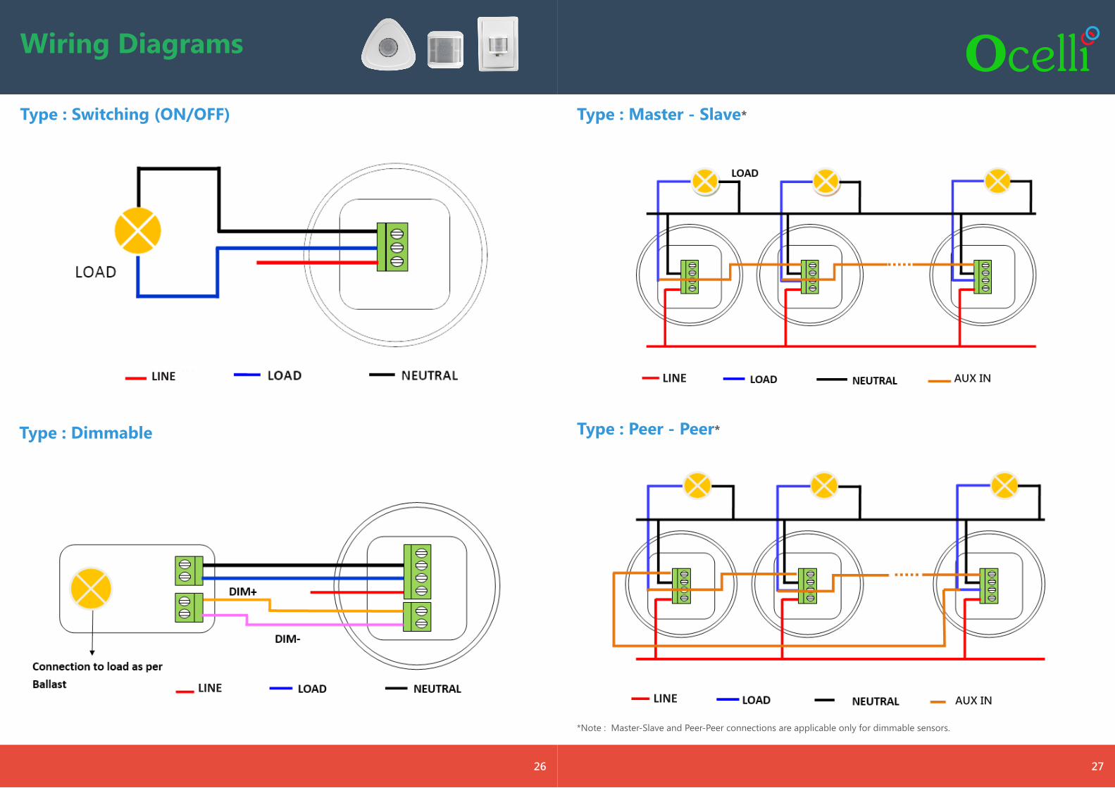
Wiring Diagrams
Type : Switching (ON/OFF)
Type : Dimmable
26
Type : Master - Slave*
Type : Peer - Peer*
27
*Note : Master-Slave and Peer-Peer connections are applicable only for dimmable sensors.
LINELINE
LINELINE
AUX IN
AUX IN