Embed Size (px)
Citation preview

Senior Design Report for
EE477 – Spring 2001
submitted by Prof. David G. Meyer
May 10, 2001
School of Electrical & Computer Engineering Purdue University

Senior Design Report EE 477 – Spring 2001
-ii-
Contents
Overview ……………………………………………………………………………………… 1
Self-Evaluation ……………………………………………………………………………….. 1
Course Policies and Procedures ………………………………………………………………. 3
Grade Determination ………………………………………………………………………….. 4
Lecture Schedule ……………………………………………………………………………… 5
Design Project Specifications ………………………………………………………………… 6
Milestones …………………………………………………………………………………….. 8
Outcome Assessment …………………………………………………………………………. 9
Appendix A: Senior Design Reports
Appendix B: Proposed Application Form
Appendix C: Proposed Evaluation Form
Appendix D: ECE Course Assessment Report

Senior Design Report EE 477 – Spring 2001
-1-
Overview One of the unique features of EE 477, Digital Systems Senior Design Project, is that each team gets to choose their own specific project (subject to some general constraints) and define specific success criteria germane to that project. In general, this approach to senior design provides students with a sense of project ownership as well as heightened motivation to achieve functionality. All project teams this semester successfully designed and built a printed circuit board, achieved at least basic functionality of their microcontroller-based hardware, and successfully integrated their application software. Some groups, in fact, continued to work on their projects after the semester was over (“just for fun”), to add features and/or obtain a higher degree of functionality. In short, students not only devoted a lot of time to this course, but they also learned a lot – in the words of several students, “more than in all their other ECE courses combined.” The complete set of Senior Design Reports is included as Appendix A. Self-Evaluation The biggest improvement realized effective with this offering of EE477 was a dedicated lab facility (room EE 69) for the course, equipped with an electronic lock to provide students with 24/7 access. The high degree of success achieved by each team was a direct result of the availability of this laboratory. Another reason for the high degree of success attained was the incredible effort put forth by our outstanding teaching assistant, Kurt Otte. There is always room for change, however, and one of our goals has always been to strive for continuous improvement. A problem endemic to any course of this type is how to deal with “slackers” – i.e., those students who try to “hide” and get by with as little work as possible. In EE 477, we attempt to deal with this kind of student several different ways. First, the 16% individual component makes it tough for a given student to completely “slack off” and still get a good grade. Second, the instructor reserves the right to lower an individual student’s success criteria score (worth 30% of the course grade) in cases where there is documented evidence (e.g., based on that student’s lab notebook) that a given student did not do his/her “fair share” of the design project – thus making it possible to significantly lower the grade of any student who did not adequately contribute to their team’s effort. Further, all team members are required to participate in their group’s design review and final presentation in order to receive credit for those components. Finally, each team member is required to document his/her individual contributions to the project in the Final Report, and to submit a confidential peer review of each teammate. In general, most of the students enrolled in EE 477 Spring 2001 worked very hard – many claiming they spent more time on EE 477 than on all their other courses combined. Areas that need improvement or change include the following. First, an enrollment of 51 (with 13 project teams) is too large (and the number of different projects too great) for a single professor and single half-time TA to effectively manage. The enrollment cap recommended in our previous report (Spring 2000) of 32 students/8 project teams should be strictly followed. Note that simply offering multiple “lecture” divisions of EE 477 is NOT a viable solution (as was done Spring 2000) – it simply compounds course administrative problems and increases the Professor’s workload. If additional faculty/staff were allocated to the course, an absolute maximum of 48 students/12 project teams could be accommodated by the current lab facility…but this option should not even be considered UNLESS ADDITIONAL FACULTY AND SUPPORT STAFF ARE ALLOCATED FOR THIS COURSE.

Senior Design Report EE 477 – Spring 2001
-2-
Second, teams could be formed more efficiently and effectively if students were required to complete an “application/information” form when they register for the course. Information gathered using such a form could be used to formulate teams that are potentially more productive and “balanced” (in terms of background, interests, and areas of expertise). A proposed form for this purpose is included as Appendix B. It will be presented to the ECE Curriculum Committee for approval this fall, with the goal of being in place before registration for the Spring 2002 semester begins. Third, individual lab notebooks varied greatly in quality – some of them were simply “narratives” of group meetings, while others appeared to be transcribed “after the fact”. We attempted to address these issues by evaluating each student’s lab notebook tear-out sheets several times throughout the semester (on a total of four different occasions). While this rather significant effort on the our part lead to notable improvements in the lab notebooks relative to previous offerings, there is still room for improvement ─ especially for team members charged with software development, who generally kept the “worst” notebooks. The fundamental problem appears to be getting students to: (a) appreciate the value of a good lab notebook, and (b) take it seriously. A possible solution might be to increase the weight of the individual lab notebook in the course grade calculation. Fourth, the course and instructor evaluation forms used by the senior design courses (in particular, EE 402 and EE 477) need to be revamped. (Currently, the forms developed for EPICS are being used by “default” – which are not a very good match to the project format and team structure used in EE 402 and EE 477.) We developed an alternative form compatible with the University’s PICES system, and used it on an experimental basis in EE477 this semester. Formal adoption of this form, included as Appendix C, will be proposed to the ECE Curriculum Committee next fall. Fifth, reasonable project goals should be more rigorously enforced. Several groups were allowed to tackle projects that the course staff suspected were too ambitious for them to successfully complete. In retrospect, more than a mere “warning” should have been issued. Sixth, while considerable effort was devoted to developing the “lecture portion” of the course, less than 50% of the students made regular class attendance a priority. The lack of motivation to attend appeared to be based on students’ lack of interest in any lecture material that did not directly apply to their particular project. Given the variety of microcontrollers and interfaces represented by the diverse set of projects completed this semester, it was difficult to make all the material we wished to cover appealing to the “masses”. One solution might be to deliver the “targeted” (i.e., microcontroller- and interface-specific) material asynchronously, using the DVJ (Digital VideoJockey) infrastructure in place, and use the scheduled classtime for interactive or cooperative learning activities (e.g., to provide additional emphasis on professionalism). Seventh, we may want to consider changing/eliminating the reference text listed for this course. The current text is somewhat dated (in terms of microcontrollers covered), yet continues to serve as a valuable resource on interfacing generic microcontrollers to a wide variety of peripherals. Finally, while most of the lab equipment is state-of-the-art, the 200 MHz computers gracing this otherwise excellent facility are definitely not. Replacing these machines should be priority.

Senior Design Report EE 477 – Spring 2001
-3-
Course Policies and Procedures Course Description: A structured approach to the development and integration of embedded microcontroller hardware and software that provides senior-level students with significant design experience applying a microcontrollers to a wide range of embedded systems (e.g., instrumentation, process control, telecommunication, intelligent devices, etc.). Both conventional microcontrollers and digital signal processors (DSPs) are considered. Objective: To provide practical experience developing integrated hardware and software for an embedded microcontroller system in an environment that models one which students will most likely encounter in industry. Instructor: Prof. David G. "Dr. D" Meyer, Office: MSEE 238, [email protected], Phone 494-3476 (messages may be left at this number 24 hours a day). Course Teaching Assistant: Kurt Otte, [email protected] Office Hours: Scheduled office hours will be posted; other times may be arranged by E-mail appointment. Please make use of the “live” consultation hours available rather than E-mailing “long” or detailed questions. Open Shop Lab: Room EE 069 is the laboratory for this course; students enrolled in EE 477 will be given a key code that will provide them with 24-hour access. This facility is equipped with expensive, state-of-the-art instrumentation; students are expected to treat the equipment and furnishings with respect. There will be a “zero tolerance” policy for abuse/misuse of this lab: anyone who does so will be unceremoniously dropped from the course and receive a failing grade; theft will be prosecuted. Reference Text (optional): John B. Peatman, Design with Microcontrollers, McGraw-Hill. Design Project: Of utmost importance in the "real world" is the ability to document and present technical information in a clear, organized, succinct, and well-illustrated fashion. In microprocessor-based designs, the ability to integrate hardware and software is a fundamental skill that should be possessed by all Computer Engineering graduates. The design project, formal written report, and videotaped presentation will give each student in this course the opportunity to develop these skills. Students will work on their design in teams of three or four. Project specifications are provided in a separate document. Oral Presentation: To further develop technical communication skills, each student will prepare and present a formal technical talk on an individually selected topic related to ethical considerations in microcontroller-based system design. These 10-minute presentations will be given during the scheduled class meetings the last 5 weeks of the semester, and count for 10% of your course grade. [NOTE: Eliminated Spring 2001 due to 50% over-enrollment] Lab Notebook: Developing good design documentation skills is an important part of this course. A significant part of your grade (10%) will be based on the individual lab notebook you maintain throughout the design and development process.

Senior Design Report EE 477 – Spring 2001
-4-
Homework: A total of 8 “homeworks” will be assigned related to key stages of the design project; together, these exercises will count for 15% of your course grade. The due dates for each are given below:
1. Preliminary Design Project Proposal (Weight: 1%, Due:1/19/01) 2. OrCAD Exercise (Weight: 2%, Due: 1/26/01) 3. Final Design Project Proposal (Weight: 2%, Due: 2/2/01) 4. Schematic and Parts List (Weight: 2%, Due 2/16/01) 5. Board Layout (Weight: 2%, Due: 3/9/01) 6. Firmware Listing (Weight: 2%, Due: 4/6/01) 7. Confidential Peer Review (Weight: 2%, Due 4/27/01) 8. ABET Senior Design Report (Weight: 2%, Due 5/2/01)
Grade Determination Your raw score (i.e., Raw Weighted Percentage or RWP) will be calculated based on the following weights:
Design Project Success Criteria Satisfaction (Each group defines their own success criteria. If all the success criteria are met, full points will be awarded; otherwise, it will be broken down according to how many of the criteria are met.)
30 %
Design Project Complexity/Degree of Difficulty (Challenging projects will get full points. This point break down will be determined when the project proposal is approved. The purpose of this requirement is to make sure "A" projects are not trivial ones.)
10 %
Design Review (Formal design reviews will be conducted mid-semester.)
10 %
Laboratory Notebook (Each student must maintain a detailed log of all project-related activities in a formal laboratory notebook.)
10 %
Oral Presentation on Engineering Ethics (Each student must give a formal technical talk.)
10 %
Homework (Several “homeworks” will be assigned related to key stages of the design project; these will serve as indicators of progress and supplant weekly reports.)
15 %
Videotaped Presentation (The final project presentations will be given during the last week of class)
10 %
Written Final Report (A complete written report of the design should be submitted with the final presentation. It should include objectives and their status, a design narrative for hardware and software, any relevant diagrams, and hard copies of the team's block diagrams, bill of materials, schematics, layouts, source code, etc.)
15 %
Your raw weighted percentage (RWP), described above, will be "curved" (i.e., mean-shifted) with respect to the upper percentile of the class to obtain a Normalized Weighted Percentage (NWP). Equal-width cutoffs will then be applied based on the Windowed Standard Deviation (WSD) of the raw class scores; the minimum Cutoff Width Factor (CWF) used will be 10 (i.e., the nominal cutoffs for A-B-C-D will be 90-80-70-60, respectively). Before final grades are assigned, the course instructor will carefully examine all "borderline" cases (i.e., NWP within 0.5% of cutoff). Once grades are assigned, they are FINAL and WILL NOT be changed.

Senior Design Report EE 477 – Spring 2001
-5-
Lecture Schedule
Tu – course intro/overview, start team formation (transparencies) Week 1 Th – project overview, documentation requirements (Mod 1 – PPT) Tu – sample project presentation (Kurt – “Predator”) Week 2 Th – project proposal guidelines, PCB layout basics (Mod 2 – PPT) Tu – OrCAD demo (Kurt) Week 3 Th – comparing alternatives, part 1 – Intel EPC (Mod 3 – PPT) Tu – comparing alternatives, part 2 – DSP (Mod 4 – PPT) Week 4 Th – supplement: back to basics (return/discuss Orcad homework) Tu – comparing alternatives, part 3 – PICs (Mod 5 – PPT) Week 5 Th – supplement: review of HC12 mux bus timing, SRAM interfaceTu – Rabbit (Mod 6 – PPT); design review preferences Week 6 Th – maintenance: peer review preferences, HC12 EVB interfacing Tu – interfacing, part 1 (Mod 7 – PPT) Week 7 Th – interfacing, part 2 (Mod 8 – PPT) Design Reviews – no class Week 8 Design Reviews – no class (no class – compensation for peer review participation) Week 9 (no class – compensation for peer review participation)
SPRING BREAK – Board Fab Tu – soldering – Kurt (Supplement – PPT) Week 10 Th – C compiler issues – Kurt (handout) Tu – 68HC12 boot-up (handout) Week 11 Th – system software organization Tu – product reliability and safety (handout) Week 12 Th – FMECA worksheet (handout) Tu – patent infringement liability (handout) Week 13 Th – patent infringement liability (web search) (no class – compensation for peer review participation) Week 14 (no class – compensation for peer review participation) Project Presentations – no class Week 15 Project Presentations – no class

Senior Design Report EE 477 – Spring 2001
-6-
Design Project Specifications Work on the design project is to be completed in teams of three or four students. The design project topic is flexible, and each group is encouraged to pick a design that uses the strengths and interest areas of their group members. The design must have the following components:
• Microprocessor: The micro can be a conventional microprocessor/microcontroller, or it can be a digital signal processor (DSP). It can range from a small 8-bit PIC or Zilog single-chip device, to an embedded microcontroller such as the Motorola HC12, to a Motorola or Analog Devices DSP, to an Intel, ARM, AMD, etc. microprocessor. These are also just a few examples to illustrate the amount of freedom in this choice. This is by no means an all-inclusive list of choices. Keep in mind you are responsible for obtaining your own parts so pick a microprocessor you can reasonably obtain. Some of the smaller micros can be sampled without too much difficulty. Some of the larger ones are expensive and require expensive tools to make development possible. These tools and chips in some cases are more difficult to sample. Each team is welcome to choose the micro of their choice, but make sure your choice is reasonable since you have to build an embedded system around that micro. A commercially available evaluation board, such as the M68EVB912B32 used in EE362, can also be used as the “heart” of your project.
• Interface to Something: Your embedded system must interface to some other device or devices. It could be a computer, or it could be some embedded device such as a Pilot, TV, etc. Some interface standards that could be used are: serial to a computer, parallel to a computer, Universal Serial Bus (USB), Firewire, Ethernet, Infrared (IR), Radio Frequency (RF), etc. This requirement again has a large amount of freedom. To help with some of the more complex interfaces such as Ethernet, USB, or Firewire there are dedicated chips, which encapsulate the lowest layers of the interface. This makes using these interfaces easier to handle but not necessarily trivial. Be sure to investigate the interface you wish to interface and make a reasonable choice. (NOTE: Interfaces involving A.C. line current require special permission – see the instructor for details.)
• Custom printed circuit board: Through the process of the design, each group will be required to draw a detailed schematic. From the schematic, a two-layer (maximum) printed circuit board will be created. The board will etched by a local board house. The team is then responsible for populating the board (solder the parts on the board), and completing the final stages of debugging and testing on their custom board.
• Be of personal interest to at least one team member: It is very difficult to devote the time and energy required to successfully complete a major design project in which you and/or your team members have no personal interest. There are lots of possibilities, ranging from toys and games to “useful and socially redeeming” household items, like audio signal processors and security systems.
• Be tractable: You should have a “basic idea” of how to implement your project, and the relative hardware/software complexity involved. For example, you should not design an “internet appliance” if you have no idea how TCP/IP works. Also, plan to use parts that are reasonable priced, have reasonable footprints, and are readily available. Be cognizant of the prototyping limitations associated with most flash-memory-based microcontrollers (like the 68HC912B32 and most PIC microcontrollers, for example).

Senior Design Report EE 477 – Spring 2001
-7-
Project Proposal Each group should submit a proposal outlining their design project idea. This proposal should not be wordy or lengthy. It should include your design objectives, design/functionality overview, and success criteria. The success criteria should include ten items, five of which are common to all groups and five of which are specific to your project. The project grade will be based in large part on how well these ten success criteria are met. The five common ones are:
• Create a bill of materials and order/sample all parts needed for the design • Develop a complete, accurate, readable schematic of the design • Complete a layout and etch a printed circuit board • Populate and debug the design on a custom printed circuit board • Write a clear, concise final report documenting the design
Forms for the preliminary and final versions of your team’s project proposal are available on the course web site. Use these skeleton files to create your own proposal. The graded project proposals will count toward the “homework” portion of your course grade.
Design Review Part way through the design process, there will be a formal design review. This is a critical part of the design process. In industry, this phase of the design process can often make or break your project. A good design review is one where a design is actively discussed and engineers present and concur with the current or amended design. The design review is in some cases the last chance to catch errors before the design is frozen, boards are etched, and hardware is purchased. A friend is not someone who rubber-stamps a design, but rather one who actively challenges the design to confirm the design is correct.
Approach the design review from a top-down, bottom-up perspective. First, present a block diagram of your design and explain the functional units. Then drop to the bottom level and explain your design at a schematic level. Be prepared to justify every piece of the design; a perfectly valid answer, however, is applying the recommended circuit from an application note. If you do use a circuit from an application note, have the documentation on hand and be able to produce it. Your grade for the design review will not be based on the number of errors identified in your design. The best engineers make mistakes, and the purpose of the design review is to catch them rather than spend hours of debugging later to find them. The design review will be graded primarily on how well the group understands their design and the professionalism with which they present it.
To facilitate the design review process, the class will be split into subgroups that will meet at individually scheduled times (the regular class meetings will be cancelled the two weeks the design reviews are scheduled). Both the presenters and the assigned reviewers will be evaluated.

Senior Design Report EE 477 – Spring 2001
-8-
Milestones Each group is responsible for setting and adhering to their own schedule; however, there are several important milestones, as listed in the table below. Always “expect the unexpected” and allow for some buffer in your schedule. Budget your time.
Week 1 Jan 8 – Jan 12 Formulate Group and Project
Week 2 Jan 15 – Jan 19 Preliminary Project Proposal due January 19
Week 3 Jan 22 – Jan 26 • Research Parts • Create Block Diagram
Week 4 Jan 29 – Feb 2 Final Project Proposal due February 2
Week 5 Feb 5 – Feb 9 • Draw Schematic • Construct Prototype • Begin Software Development • Create Bill of Materials • Begin Ordering/Sampling Parts Week 6 Feb 12 – Feb 16 Schematic due February 16
Week 7 Feb 19 – Feb 23 • Prepare for Design Review
Week 8 Feb 26 – Mar 2 Design Reviews (individually scheduled)
Week 9 Mar 5 – Mar 9 Board Layout due March 9
Spring Break Mar 12 – Mar 16 Board Runs
Week 10 Mar 19 – Mar 23
Week 11 Mar 26 – Mar 30 • Continue Software Development • Populate Circuit Board
Week 12 Apr 2 – Apr 6 Firmware Listing Due April 6
Week 13 Apr 9 – Apr 13
Week 14 Apr 16 – Apr 20
• Debug Hardware on Printed Circuit Board • Hardware/Software Integration and Testing • Write Report and Prepare Presentation
Week 15 Apr 23 – Apr 27 Project Demonstrations and Final Presentations
Week 16 Apr 30 – May 4 Final Reports Due May 2

Senior Design Report EE 477 – Spring 2001
-9-
Outcome Assessment In order to successfully fulfill the course requirements and receive a passing grade, each student is expected to demonstrate the following outcomes: (i) an ability to apply knowledge obtained in earlier coursework and to obtain new
knowledge necessary to design and test a microcontroller-based digital system [1, 2, 3, 4, 5; a, b, c, e, i, j, k]
(ii) an understanding of the engineering design process [4, 6, 7; b, c, e, f, h] (iii) an ability to function on a multidisciplinary team [6, 7; d, h, j] (iv) an awareness of professional and ethical responsibility [6, 7; f, h, j] (v) an ability to communicate effectively, in both oral and written form [6; g] The following instruments were used to assess the extent to which these outcomes were demonstrated (the forms used to “score” each item can be found on the course web site):
Outcome Evaluation Instruments Used (i) Homeworks 2, 4, 5, and 6; Project Demo; Final Report (ii) Homeworks 1, 3, and 8; Individual Lab Notebooks (four evaluations) (iii) Homework 7 and the “Individual Contributions” Section in both the Final
Presentation and the Final Report (iv) “Reliability and Safety” and “Patent Infringement Liability” sections in both the
Final Presentation and the Final Report (v) Formal Design Review, Peer Evaluations of Design Review, Final Presentation,
and Peer Evaluations Final Presentation For Spring 2001, the following results were obtained: • all 13 teams were able to demonstrate basic functionality of their completed project, and all
13 teams submitted a Final Report, thus satisfying Outcome (i) • all 13 teams submitted Project Proposal and Senior Design Report (the collection of which is
included as Appendix A), and all 51 students submitted tear-out sheets from their Individual Lab Notebooks, thus satisfying Outcome (ii)
• all 13 teams included an “Individual Contributions” section in their Final Presentation and Final Report, and all 51 students submitted a confidential peer evaluation, thus satisfying Outcome (iii)
• all 13 teams included “Reliability and Safety” and “Patent Infringement Liability” sections in their Final Presentation and Final Report, thus satisfying Outcome (iv)
• all 13 teams participated in the Design Review and gave a Final Presentation of their project, and all 51 students participated in the peer review process, thus satisfying Outcome (v)
In summary, all 51 students enrolled in EE 477, Spring 2001 successfully demonstrated the five course outcomes required to receive a passing grade.
The official ECE Course Assessment Report for EE 477 is included as Appendix D.

Appendix A:
Senior Design Reports

Senior Design Report EE 477 – Spring 2001
-A1-
Purdue ECE Senior Design Semester Report Semester / Year Spring 2001 Course Number and Title EE 477 Digital Systems Senior Design Project Team Name Group 1 - Big Red Button Advisors Prof. Meyer and Kurt Otte Project Title ECEOPOLY
Senior Design Students
Name Major Area of Expertise Expected Graduation Date
Shawn Jordan CmpE Hardware May 2001 Robert Stiasny CmpE Software architecture May 2001 Mark Van Regenmorter CmpE Software architecture May 2001 Ganesh Viswanathan CmpE Software May 2001
Project Description: Provide a brief (one page) technical description of the design project, as outlined below: (a) Summary of the project, including customer, purpose, specifications, and a summary of the
approach. The purpose of our project was to design and build a digital Monopoly-like game, using unique user interfaces, a printed circuit board with a microcontroller and peripheral hardware, and a physical game board with position/path LEDs and bicolor house/hotel LEDs. The intended “customer” who would be interested in this game would be anyone who wants a unique Monopoly-like game, and ECE students at Purdue. As we designed the game board in a modular fashion, the paper game board overlay could be changed to fit other customers, such as changing it to MEOPOLY for mechanical engineering students. We specified that the entire system have the “look and feel” of a board game, yet provide the players with a unique digital interface that would ensure that the game would be played by the rules. We approached this project by doing an overall architecture design, doing part selections, creating the schematic, laying out the board, writing software drivers, constructing the board, constructing the peripherals, and testing both the hardware and software, and integrating them together. (b) Description of how the project built upon the knowledge and skills acquired in earlier ECE
coursework. This project brought in aspects from almost every part of our previous ECE coursework. We used circuit analysis techniques to design our schematic, test our modules, and select appropriate parts. We used our microcontroller interfacing skills from EE362 to help us write the embedded

Senior Design Report EE 477 – Spring 2001
-A2-
software, debug hardware interfaces, and design our schematic. We used software techniques to help us develop algorithms, write code, and then create test cases for our code. (c) Description of what new technical knowledge and skills, if any, were acquired in doing the
project. Over the course of this semester, all group members learned a great deal about real hardware design. In previous coursework we had never really built an entire system from the “ground up” and integrated a complex system of embedded software and hardware. We all learned soldering techniques, compare different pieces of digital hardware, circuit testing techniques, and various debugging methods. We also learned how to correctly read and understand product data sheets. (d) Description of how the engineering design process was incorporated into the project. The first major step in the design process was the creation and submission of a design proposal. We developed our success criteria to reflect the parts of the design we felt were most critical. Developing an overall hardware design, we looked for and procured components that would allow us to accomplish our success criteria. After creating a schematic design of our board, we laid it out using Orcad. Then the board was etched and drilled. Once we received our board, we began populating the board with our components and wrote the software drivers to control the hardware. We built the physical game board and began testing overall parts of the system. We spent a great deal of time debugging and tweaking parts of our circuits and software. Whenever a major change was made in the project, we submitted a change order request. We also kept good records of all of the changes we made at various stages of design, so that we would be able to go back to a previous version if there was an issue. (e) Description of the multidisciplinary nature of the project. This project incorporated a large amount of hardware with a large amount of software. We had to design our software to set up signal communication between various components, and use a great deal of hardware design to ensure proper operation. We had to take physical size limitations into account, and use circuit analysis to figure out power requirements, resistor values, fanin/fanout issues, etc. (f) Summary of how realistic design constraints were incorporated into the project (where
appropriate, include economic, environmental, ethical, health & safety, social, and political constraints as well as considerations related to sustainability and manufacturability)
We had a lot of design constraints in the project for a variety of reasons. As far as board space was concerned, we had a lot of components which all had a great number of signals that needed to be routed. Due to the process used to create our boards, we were limited to a 2-layer board with no through-plated vias. We had to do a lot of work on routing to make sure all of the signals made it from their origin to their destination. As we are all seniors in college, our budget was limited, so we tried to get as many of our components donated or sampled as possible. As far as safety was concerned, our game board and PCB draw a large amount of current, so we made sure that our power supply could handle the amount of power, and used an inline fuse to prevent current from flowing in case of a short circuit. We also used heat shrink tubing to prevent the LED leads from shorting out.

Senior Design Report EE 477 – Spring 2001
-A3-
Purdue ECE Senior Design Semester Report Semester / Year Spring 2001 Course Number and Title EE 477 Digital Systems Senior Design Project Team Name Group 2 Advisors Prof. Meyer and Kurt Otte Project Title Self-Guided Blimp
Senior Design Students
Name Major Area of Expertise Expected Graduation Date
Pawin Suthapong CmpE Embedded Software May 2001 Bahaa Fahim CmpE Computer Architecture May 2001 Jason Horihan CmpE Networks May 2001 Keith Banks CmpE Computer Architecture December 2001
Project Description: Provide a brief (one page) technical description of the design project, as outlined below: (a) Summary of the project, including customer, purpose, specifications, and a summary of the
approach. Our goal was to design and build a self-guided blimp, which is capable of following a series of way-points to a final destination. This design was originally intended as a children's toy, but due to the extreme costs involved in producing it we changed our focus to finding other uses of our product. The application which best suited our project was as a mobile platform for a camera during sporting events. Inside the large domes of most major sports teams our GPS will function and we will have sufficient room to maneuver. Specifications for our project were largely dictated by the balloon's physical characteristics. We had to keep our payload weight under 3 pounds and needed motors that could sufficiently propel the blimp. Since we could not use the pulse width modulation pins from the HC12 to drive the motors directly we looked for a chip which would function as a power MOSFET and allow us to reverse the polarity so that we could go both backwards and forwards with one PWM channel. The selection of our motor control chip in turn dictated our power supply and thus our motors. This was the way our entire project was designed: requirements lead to the selection of a particular part which in turn imposed additional requirements and so on. (b) Description of how the project built upon the knowledge and skills acquired in earlier ECE
coursework. The greatest benefit to us in this project was the training in both assembly level programming and data sheet analysis that we received in EE 266. We avoided many pitfalls by reading data sheets and in one case we were able to make a design correction because when problems arose we knew how to interpret the information and understand the problem. Since our GPS operated on 3.3 volt logic we thought there might be a problem interfacing it with the HC12, but the data sheets said that it was five volt tolerant so we thought this would not be a problem. While this

Senior Design Report EE 477 – Spring 2001
-A4-
was true that only worked as far as inputs were concerned. To fix this we used an inverter which had a VIH which was 3 volts and then fed the output of the inverter back into another inverter thus creating a 3 volt to 5 volt logic converter. (c) Description of what new technical knowledge and skills, if any, were acquired in doing the
project. The technical skill that was most improved for the two members of the hardware team was our soldering. Having never done it before it took a couple of attempts with smaller integrated circuits before we felt confident enough to tackle something like the HC12 80 pin quad flat pack. However towards the end of the project we removed an HC12 so cleanly that we were actually able to re-solder it to the board without damaging it. The software development team learned more than the bargained for about compilers. They spent numerous hours configuring their make file and declaring variable types so that their software would compile and run on the HC12. They also had to deal with memory constraints imposed by the HC12 and had to reorganize their code so that the stack would not exceed the 2K of RAM. (d) Description of how the engineering design process was incorporated into the project. Towards the final days of our project we ran a stress test on the motor controllers to make sure that they could handle the amount of current that our motors would be drawing. The motors would shut down frequently and after a while they would turn back on and run for a while longer. First we examined the software to make sure the PWM registers were not getting overwritten. Once we had eliminated software as the cause we realized that the chips were going into thermal shutdown and then turning back on only after they had cooled sufficiently. To fix this we mounted a huge heat sink to the back of the motor controllers and reran the stress test. This time the motors ran up until the battery was exhausted. (e) Description of the multidisciplinary nature of the project. The multidisciplinary nature of our project is easy to see. The analog compass provided an electrical engineering challenge due to its analog nature. The HC12 was a computer engineering problem. In writing the software for the pocket PC many computer science challenges arose in trying to structure the data so that it would not take up too much room and yet be easily understood. (f) Summary of how realistic design constraints were incorporated into the project (where
appropriate, include economic, environmental, ethical, health & safety, social, and political constraints as well as considerations related to sustainability and manufacturability)
In our design of this project economics has been one of the primary concerns because we wanted to spend as little as possible. But as project costs skyrocketed it became apparent that this would not be feasible as a children's toy and that a commercial application would be necessary. As far as safety concerns go we really only have one, the gas that is used to fill the balloon. Although hydrogen has more lift capability, helium was used because it is not flammable. The possibility of the balloon bursting and causing respiratory problems is minor due to the mylar material that we used to construct the balloon. When a hole is punched in our balloon envelope the escaping

Senior Design Report EE 477 – Spring 2001
-A5-
gas will rip new holes in the balloon along the seams so that there will be minimal explosive force. However in a poorly ventilated room asphyxiation is a possibility which is another reason why we switched our perception of this product from a children's toy to a floating camera or billboard.

Senior Design Report EE 477 – Spring 2001
-A6-
Purdue ECE Senior Design Semester Report Semester / Year Spring 2001 Course Number and Title EE 477 Digital Systems Senior Design Project Team Name Group 3 Advisors Prof. Meyer and Kurt Otte Project Title Infrared Repeater for Home Entertainment
Senior Design Students
Name Major Area of Expertise Expected Graduation Date
Vivek Thakkar CmpE Software May 2001 Jacob Carson CmpE Hardware May 2001 Jennifer Bulfin CmpE Hardware May 2001 Ryan Anderson CmpE Software May 2001
Project Description: Provide a brief (one page) technical description of the design project, as outlined below: (a) Summary of the project, including customer, purpose, specifications, and a summary of the
approach. The home entertainment infrared relay system was designed for the consumer who needs to relay an infrared signal through physical barriers in a home environment and also receive the audio feedback to the transmitting location. The system was designed to allow a user to send an infrared signal to a device using its original remote or to pre-program the original remote commands into our device. Then the remote or pre-programmed buttons can be used to relay the equivalent infrared signal over a RF link through physical barriers and transmit it into the respective receiving device – also allowing for the audio feedback from the IR device to be routed through our RF signal transceivers back to the IR originating location. (b) Description of how the project built upon the knowledge and skills acquired in earlier ECE
coursework. This project used cumulative knowledge gained from several courses in the Computer Engineering curriculum. Course of note are EE 201/202/255 (Linear Circuit Analysis), EE 266 (Digital Logic Design), and EE 362 (Microcontrollers). (c) Description of what new technical knowledge and skills, if any, were acquired in doing the
project. Several skills were improved upon and learned during the development of our senior design project. This was our first board design done with Orcad Capture and Layout. Great experience was gained debugging board-level issues and populating the boards with components. We also learned about infrared and audio transmission, and how to generate a carrier frequency.

Senior Design Report EE 477 – Spring 2001
-A7-
(d) Description of how the engineering design process was incorporated into the project. The engineering design process was incorporated throughout the development of our project. First, a consensus was reached on what our product was to do and how we were going to do it. Next, components were researched to find the best and most cost-effective way to build our product. A design review held with our peers was conducted for feedback. A board was designed, sent out to be manufactured, populated, tested, tuned up, and debugged. Software to control the components was developed. Safety issues were taken into consideration all along the way. (e) Description of the multidisciplinary nature of the project. This project required all the members of our team to play various roles from the overall physical design, electrical circuitry design, and down to the level of microcontroller programming. Allowing us to touch the fields of mechanical engineering in designing and building the physical layout, while using electrical engineering skills to design the power circuitry, and using computer engineering knowledge to write and debug the software which handled the logic within our device. (f) Summary of how realistic design constraints were incorporated into the project (where
appropriate, include economic, environmental, ethical, health & safety, social, and political constraints as well as considerations related to sustainability and manufacturability)
Our project fit within realistic design constraints. To keep the overall cost low, we used inexpensive parts. Our device uses a simple 5 volt regulated power supply (wall adapter) and would pose very few electrical or health safety issues. Due to the modular design, the device is also easily maintainable and manufacturable.

Senior Design Report EE 477 – Spring 2001
-A8-
Purdue ECE Senior Design Semester Report
Semester / Year Spring 2001 Course Number and Title EE 477 Digital Systems Senior Design Project Team Name Group 4 Advisors Prof. Meyer and Kurt Otte Project Title Data Acquisition Device for Palm Computing Device
Senior Design Students
Name Major Area of Expertise Expected Graduation Date
Kris Boultbee EE Software May 2001 John Field CmpE Testing May 2001 Heath Lord CmpE VHDL Coding May 2001 Adam Zysk EE Hardware May 2001
Project Description: Provide a brief (one page) technical description of the design project, as outlined below: (a) Summary of the project, including customer, purpose, specifications, and a summary of the
approach. A digital voltmeter and data acquisition / logging device was created to be used with a Palm computing device. Basic voltmeter features along with more advanced data management tools were implemented using the Palm device as the user interface and storage device. (b) Description of how the project built upon the knowledge and skills acquired in earlier ECE
coursework. The project utilized a great deal of our knowledge from previous coursework. The software development utilized knowledge from VHDL and C courses. Hardware concerns involved a variety of coursework, including circuits, digital design, signals & systems, and semiconductor devices. (c) Description of what new technical knowledge and skills, if any, were acquired in doing the
project. The tasks associated with PC board design and layout fostered the development of new skills. Additionally, exposure to serial interfacing protocols, analog to digital conversion devices, and precision amplifiers led to knowledge in these fields. Team members also gained additional experience implementing complex VHDL and high-level coding schemes. (d) Description of how the engineering design process was incorporated into the project. Frequent, periodic team meetings were held to determine the optimal design and development paths for our project. Our project development was stimulated by a series of goals that were

Senior Design Report EE 477 – Spring 2001
-A9-
slated to be met every couple of weeks. This system helped the team stay focused and keep to a schedule that ensured successful completion of the task at hand. (e) Description of the multidisciplinary nature of the project. The project was multidisciplinary in the sense that it spanned a variety of knowledge areas. Concepts were applied from fields such as mechanics, thermal, semiconductor, circuits, software, power, and communications engineering. (f) Summary of how realistic design constraints were incorporated into the project (where
appropriate, include economic, environmental, ethical, health & safety, social, and political constraints as well as considerations related to sustainability and manufacturability)
A variety of constraints were placed on our project, especially relating to safety, economics, and sustainability. Our safety constraints related mainly to protection against higher than intended input voltages. From an economic standpoint, our component selection criteria relied heavily on cost analysis. Additionally, sustainability concerns prompted us to add a calibration feature that would allow for long-term, precise operation.

Senior Design Report EE 477 – Spring 2001
-A10-
Purdue ECE Senior Design Semester Report Semester / Year Spring 2001 Course Number and Title EE 477 Digital Systems Senior Design Project Team Name Group 5 Advisors Prof. Meyer and Kurt Otte Project Title Go Speed Racer
Senior Design Students
Name Major Area of Expertise Expected Graduation Date
Jacob Pennock CmpE Hardware May 2001 Logan Brooks CmpE Hardware May 2001 Jason Smith CmpE Hardware May 2001 Lowell Smith CmpE Software December 2001
Project Description: Provide a brief (one page) technical description of the design project, as outlined below: (a) Summary of the project, including customer, purpose, specifications, and a summary of the
approach. Our goal was to develop a remote control car with obstacle avoidance ability. We wanted to see the possibilities of extending current uses of obstacle detection. This is a system that is designed just for use with RC cars, but could possibly be extended to meet customer needs for automobiles. Our approach was to use sensor data to override user control of the car when it was in an unfavorable situation. (b) Description of how the project built upon the knowledge and skills acquired in earlier ECE
coursework. This project required knowledge from much of our previous coursework. Knowledge of transducers, transistors, and general integrated circuits was necessary for completion of this project. Knowledge of the Motorola HC12 was very important and acquired from previous coursework. (c) Description of what new technical knowledge and skills, if any, were acquired in doing the
project. We learned many more technical skills from this project. It gave us a much better working experience with hardware components, and what they do. IC components that we had never dealt with before were introduced to us. Some of us had never routed or populated a board. We also had to consider the safety and copyright issues that had been left untouched by much of our earlier coursework.

Senior Design Report EE 477 – Spring 2001
-A11-
(d) Description of how the engineering design process was incorporated into the project. In the process of design, we took many steps as we would in industry. We formulated our own ideas and plans for hardware and software. We used previously designed projects as examples so we would not make mistakes that have been made before. We created a hardware design using schematics and layouts. A design review was completed with our peers, and the board was fabricated. The software was implemented as planned. Testing was continuously being done since we would not have much time after completion. A final presentation and report were completed and archived. (e) Description of the multidisciplinary nature of the project. Most of us had not worked on such an integrated project. We had not had the experience of a multifaceted design project before. Previous classes just introduced us to individual portions of an overall design. The project required both a hardware and a software aspect of the design. While designing the hardware, we needed to take into consideration the software aspect, too, and vice versa. We needed to understand exactly what the chip (HC12) was capable of doing in hardware and software. And in the end, we learned how to combine the hardware and software together into the completed project. (f) Summary of how realistic design constraints were incorporated into the project (where
appropriate, include economic, environmental, ethical, health & safety, social, and political constraints as well as considerations related to sustainability and manufacturability)
One of the major constraints that were encountered was that of time. Along with other classes, only a portion of our time could be dedicated to this project. Another constraint that we could not deal with was the fiscal constraint put upon us by college life. We found many parts that would have been useful but were unable to afford such high priced components. Excluding the time constraint, and allowing a few changes, we feel that our project would be easily manufactured in large numbers.

Senior Design Report EE 477 – Spring 2001
-A12-
Purdue ECE Senior Design Semester Report Semester / Year Spring 2001 Course Number and Title EE 477 Digital Systems Senior Design Project Team Name Group 6 Advisors Prof. Meyer and Kurt Otte Project Title N.A.M.P.
Senior Design Students
Name Major Area of Expertise Expected Graduation Date
Josh King EE Software August 2001 Greg Crocker EE Software May 2001 Scott Howell EE Hardware May 2001 Chris Guenther EE Hardware May 2001
Project Description: Provide a brief (one page) technical description of the design project, as outlined below: (a) Summary of the project, including customer, purpose, specifications, and a summary of the
approach. N.A.M.P. (NOT JUST ANOTHER MP3 PLAYER) is essentially an Internet radio receiver for SHOUTcast stations. SHOUTcast is an Internet broadcasting technology that streams music compressed using the MP3 (MPEG 1/2, Layer 2/3) format. After connecting it to a network, the station is “tuned in” by specifying the IP address of the SHOUTcast server. RCA jacks allow the audio to be played through the home entertainment system. N.A.M.P. is easy and intuitive to use. The user can scroll through an existing list of stations using the on-board buttons, or connect over the Web and change the settings remotely. This project had to encompass several different components, or modules, to make it work. The first is the MP3 decoder and digital-to-analog converter. MP3 data is transmitted serially to the decoder, and analog music plays out of the RCA jacks. The second module is the microcontroller, which handles all data transfers from the device input (Internet) to the decoder module. This requires a fairly large amount of RAM (512KB) for buffering. Third is the ethernet interface to connect to the Internet. Data comes streaming in through here to be buffered and transferred by the microcontroller. Lastly, the UI module contains the LCD panel and on-board buttons to allow the user to control the setting. (b) Description of how the project built upon the knowledge and skills acquired in earlier ECE
coursework. Since this project’s primary focus was the integration of a microcontroller with other devices, earlier courses in this area were of key importance. EE362 provided the groundwork for programming and interfacing microprocessors, while EE365 gave a more fundamental understanding of the processor itself. To delve below the abstractions of the digital world,
Senior Design Report EE 477 – Spring 2001
-A13-
earlier analog classes discussing fundamental EE concepts were crucial. Kirchoff’s Laws and linear circuit analysis techniques, learned in EE201 and EE202, laid a framework for design. Most real-world designs use non-linear elements such as diodes and transistors, which were taught in EE255. This knowledge was important in several areas of the project such as adding non-linear elements to the design, using level translating buffers, and understanding how different I/O pins work (i.e. some outputs can drive a line high, while others need pull-up resistors). The microcontroller used included a C compiler, so classes such as EE264 and EE368 allowed for the use of advanced programming techniques. Electrical engineering as a whole, as well as all engineering disciplines, is about solving problems, which is key to providing engineering solutions. So in reality, all the classes, even in unrelated areas, helped in some way to make this project happen. (c) Description of what new technical knowledge and skills, if any, were acquired in doing the
project. Almost all of the undergraduate EE courses are about theory. While this understanding is very important to have, engineering is not about the theory but about applying it. This is why EE477 is important because it shows that, not only do these concepts work on paper, they actually produce real-world results. Of the more concrete skills learned, one of the most significant has to be the Orcad Tools package, including schematic design and board layout techniques. Before this semester, a capacitor was described solely by its capacitance. Now we’ve learned that there are different types like electrolytic, ceramic, and tantalum; and different packages such as surface mount and leaded, radial and axial; and a slew of other parameters such as rated voltage and equivalent series resistance. This happened across the board, with resistors and caps, inductors and regulators, chips and DIPs. Board layout was totally foreign; all the theoretical abstractions went out the window. Make sure the traces are wide enough; no right angle turns allowed; reduce via count; separate analog and digital power and ground; what do you mean you have to translate a 5V logic high to a 3.3V logic high? (d) Description of how the engineering design process was incorporated into the project. The project was broken up into tasks by its functional groups. Then these tasks were divided up among the team members to allow everyone to work in parallel, fully utilizing all the manpower available. At least that was the theory. The tasks were split up originally, but there was such a learning curve involved in all aspects of the project, that to complete any task, it required input from all the members. In the future, it would be good to not only divide tasks by functional grouping, but also by team member’s strengths and weaknesses. This would not have worked here because the whole course was a weak point for all of us in the beginning. (e) Description of the multidisciplinary nature of the project. N.A.M.P. was able to span a variety of disciplines from all aspects of life, ranging from electrical engineering to computer engineering. Unfortunately this project did not include much interaction with people from other disciplines, engineering or otherwise. The class is overall a good simulation of real-world projects.

Senior Design Report EE 477 – Spring 2001
-A14-
(f) Summary of how realistic design constraints were incorporated into the project (where appropriate, include economic, environmental, ethical, health & safety, social, and political constraints as well as considerations related to sustainability and manufacturability)
Since this was a learning experience, the primary focus was on a project that would do something interesting, and less on how marketable or practical it was. There was no original list of constraints for which to optimize, just those that were implied in the project description and design. The first of these was cost; the money was not available to choose just any design platform or component. The second was reliability, because without this, no one would want our product. In the category of most underrated constraint, the winner would certainly have to be that of time. Our original design included a hard drive interface and infrared remote receiver, in addition to the features listed above. Even after trimming those off, the project was still left unfinished by the end of the semester. In the consumer product industry, time-to-market is of extreme importance, so this should certainly have been considered carefully. But it is better to learn the lesson in this environment than in industry where the penalty is much more severe.

Senior Design Report EE 477 – Spring 2001
-A15-
Purdue ECE Senior Design Semester Report
Semester / Year Spring 2001 Course Number and Title EE 477 Digital Systems Senior Design Project Team Name Group 7 Advisors Prof. Meyer and Kurt Otte Project Title Flying Pics
Senior Design Students
Name Major Area of Expertise Expected Graduation Date
Chris Positano CmpE Software May 2001 Brent Sandquist CmpE Hardware May 2001 Jason Adams CmpE Hardware May 2001 Frank Panatera CmpE Software December 2001
Project Description: Provide a brief (one page) technical description of the design project, as outlined below: (a) Summary of the project, including customer, purpose, specifications, and a summary of the
approach. Wireless RF technology was used to design a remote imaging system for the Handspring Visor PDA. The system is composed of two parts, an “expansion module” for the Handspring Visor PDA that contains an RF receiver and Palm OS application, and the remote sensing system with a micro-controller (Rabbit 2000), RF transceiver, and an interface to a consumer digital camera. Images would be sent by the remote unit over RF and displayed on the PDA’s LCD. The customer would be someone who enjoys new technologies with a budding interest in photography. (b) Description of how the project built upon the knowledge and skills acquired in earlier ECE
coursework. Our project built greatly upon earlier coursework. It required C programming language skills, which each team member was well versed in due to the multiple classes (EE 264, 368) involving this language. From our digital systems classes (EE 266, 362), we gained valuable knowledge in embedded systems and interfacing. (c) Description of what new technical knowledge and skills, if any, were acquired in doing the
project. Many new skills were acquired in this project. These included: component selection and research, soldering, board layout, embedded systems programming, wireless communication protocol, hardware and software debugging skills, implementation methodology, and group skills.

Senior Design Report EE 477 – Spring 2001
-A16-
(d) Description of how the engineering design process was incorporated into the project. The process was incorporated into the project in many ways. Initially, we had to brainstorm, research, and select a project and it’s component. We also had to be cognizant of the budget that our group decided upon. Both software and hardware design had to take place separately and then tested and interfaced together in the end. (e) Description of the multidisciplinary nature of the project. Our project is not very multidisciplinary in nature. Most of the project required engineering design skills. However, we did utilize other skills in communicating with companies for parts, creating the budget, and presenting our project both orally and written. (f) Summary of how realistic design constraints were incorporated into the project (where
appropriate, include economic, environmental, ethical, health & safety, social, and political constraints as well as considerations related to sustainability and manufacturability)
There were serious constraints with the physical board, in that the “low tech” boards were unable to handle many of the possible components we could have selected. Economically, several components were ruled out due to their expense.
Senior Design Report EE 477 – Spring 2001
-A17-
Purdue ECE Senior Design Semester Report
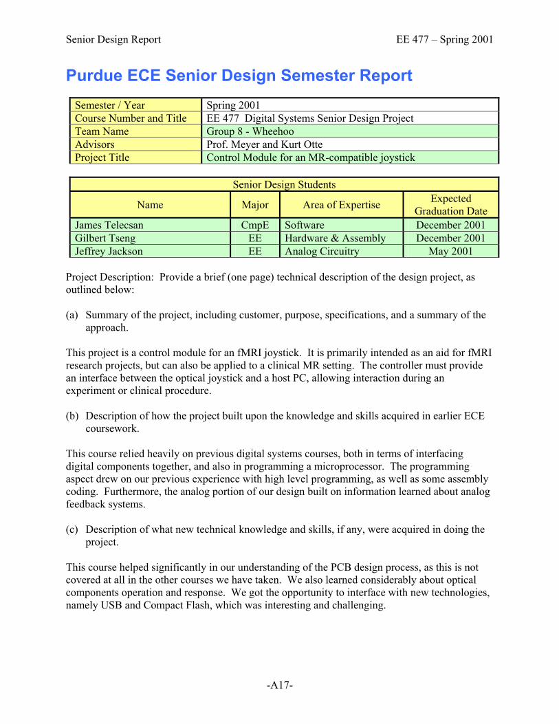
Semester / Year Spring 2001 Course Number and Title EE 477 Digital Systems Senior Design Project Team Name Group 8 - Wheehoo Advisors Prof. Meyer and Kurt Otte Project Title Control Module for an MR-compatible joystick
Senior Design Students
Name Major Area of Expertise Expected Graduation Date
James Telecsan CmpE Software December 2001 Gilbert Tseng EE Hardware & Assembly December 2001 Jeffrey Jackson EE Analog Circuitry May 2001
Project Description: Provide a brief (one page) technical description of the design project, as outlined below: (a) Summary of the project, including customer, purpose, specifications, and a summary of the
approach. This project is a control module for an fMRI joystick. It is primarily intended as an aid for fMRI research projects, but can also be applied to a clinical MR setting. The controller must provide an interface between the optical joystick and a host PC, allowing interaction during an experiment or clinical procedure. (b) Description of how the project built upon the knowledge and skills acquired in earlier ECE
coursework. This course relied heavily on previous digital systems courses, both in terms of interfacing digital components together, and also in programming a microprocessor. The programming aspect drew on our previous experience with high level programming, as well as some assembly coding. Furthermore, the analog portion of our design built on information learned about analog feedback systems. (c) Description of what new technical knowledge and skills, if any, were acquired in doing the
project. This course helped significantly in our understanding of the PCB design process, as this is not covered at all in the other courses we have taken. We also learned considerably about optical components operation and response. We got the opportunity to interface with new technologies, namely USB and Compact Flash, which was interesting and challenging.

Senior Design Report EE 477 – Spring 2001
-A18-
(d) Description of how the engineering design process was incorporated into the project. The biggest demands in this project were teamwork and communication, both essential components of the engineering design process. We each designed separate parts of the project, both in the hardware and software phases of the design, and had to have our respective parts of the project completed by a determined deadline so that all of the components could be integrated into one complete picture. We kept up with hardware and software binders to ensure that all changes were documented and each team member could easily understand how the rest of the project functioned. (e) Description of the multidisciplinary nature of the project. There were many different facets to the project that were challenging to us. Beyond the digital design and programming, we implemented analog feedback loops to control the light output of the optical transmitters. We also constructed a metal housing for the project. We designed and constructed a test box to physically simulate the function of the joystick. (f) Summary of how realistic design constraints were incorporated into the project (where
appropriate, include economic, environmental, ethical, health & safety, social, and political constraints as well as considerations related to sustainability and manufacturability)
One of the major design considerations for this project is portability. Since for research purposes we do not have full-time access to an MR environment, it is essential that our project have a quick setup/teardown time, and that the space usage is minimal for transportation. We also needed to maintain strict compliance with the restrictions of the MR environment for health reasons. Inside the magnetic field, ordinary metallic materials become potential conductors for current loops that could be hazardous to subjects or patients and must be strictly avoided.

Senior Design Report EE 477 – Spring 2001
-A19-
Purdue ECE Senior Design Semester Report Semester / Year Spring 2001 Course Number and Title EE 477 Digital Systems Senior Design Project Team Name Group 9 Advisors Prof. Meyer and Kurt Otte Project Title SHARC (Spoken Home Automation Remote Control)
Senior Design Students
Name Major Area of Expertise Expected Graduation Date
Matthew Hageman EE Hardware May 2001 Joseph Richards CmpE Software May 2001 Kostya Reverdatto CmpE Hardware December 2001 Michael Crogan CmpE Software May 2001
Project Description: Provide a brief (one page) technical description of the design project, as outlined below: (a) Summary of the project, including customer, purpose, specifications, and a summary of the
approach. For this project, a remote control unit was designed. The unit functions entirely on voice commands and is programmable by pushbuttons. It is used to control devices with infrared receivers and also control appliances and lighting through X10 modules. This product is intended for today’s “high tech gadget” market, and should be popular with most consumers. It also has application to people with disabilities that have problems using remote controls. A hardware solution was used for voice recognition via a Voice Direct 364 design kit. A Motorola HC12 microcontroller was used as the host processor of the unit. The hardware was designed and laid out by two of the group members and then handed off to the other two group members for software design. (b) Description of how the project built upon the knowledge and skills acquired in earlier ECE
coursework. Circuit design skills learned in courses like EE 201 and EE 202 were extremely helpful in the hardware design and analysis aspect of this project. When designing circuits with transistors, knowledge from EE 255 was used. Knowledge about the Motorola HC12 and its capabilities was used from EE 362. Assembly language, also learned in EE 362, along with software skills acquired in such courses as EE 264, EE 364, and EE 368, were essential for software design aspect of the project.

Senior Design Report EE 477 – Spring 2001
-A20-
(c) Description of what new technical knowledge and skills, if any, were acquired in doing the
project. A great deal of practical design skills were acquired and reinforced in doing this project. New hardware skills acquired were: power circuit design, infrared circuits design, X10 circuit design, and board layout. New software skills learned were: Voice Direct protocol, X10 protocol, and infrared protocols. Skills that were reinforced through this project were: schematic design, soldering, hardware debugging, assembly coding, and testing equipment usage. (d) Description of how the engineering design process was incorporated into the project. This project involved both intensive software design and intricate hardware design. The team of 4 people was split into 2 smaller teams of 2 members each. The first team focused on the hardware design, and the other focused on the software design. The members of the software design team contributed in the selection of hardware components that would satisfy their software needs. The hardware was designed with the thought of software programmability in mind. The software was then designed on top of what the hardware could provide. Overall, good communication among members made this project a success. (e) Description of the multidisciplinary nature of the project. One Electrical Engineer and three Computer Engineers worked on this project. The EE and one CmpE student formed the hardware team and made the schematic, laid out the board, and debugged the hardware. The other two CmpE students dealt mainly with software design. However, roles changed throughout the project. A hardware team member would always be on call for software team questions or problems. The EE even fixed the infrared transmit clock software, while the software team worked on other more important tasks.
(f) Summary of how realistic design constraints were incorporated into the project (where appropriate, include economic, environmental, ethical, health & safety, social, and political constraints as well as considerations related to sustainability and manufacturability)
Our major design constraint was time. We had to keep a strict schedule in order to accomplish our goals. We followed our timeline, and even had to expand it until graduation so that we would be able to display our project at the graduation reception. This could be considered a social constraint, finishing for a major demonstration. As for an economical constraint, we never considered the unit price because it was a prototype. In future versions, unit price will be a major consideration. Another major consideration will be manufacturability, because some parts were not needed and a different microcontroller could have been implemented.

Senior Design Report EE 477 – Spring 2001
-A21-
Purdue ECE Senior Design Semester Report Semester / Year Spring 2001 Course Number and Title EE 477 Digital Systems Senior Design Project Team Name Group 10 Advisors Prof. Meyer and Kurt Otte Project Title Purdue Weather Station
Senior Design Students
Name Major Area of Expertise Expected Graduation Date
Ryan Traylor EE Controls May 2001 Dan Hromis CmpE Hardware-Software Integration May 2001 Deserina Deserina CmpE Software Development May 2001 Hardiyanto Wibisono CmpE Software Development May 2001
Project Description: Provide a brief (one page) technical description of the design project, as outlined below: (a) Summary of the project, including customer, purpose, specifications, and a summary of the
approach.
A weather station is implemented to measure the current weather conditions such as temperature, air pressure, wind direction, wind speed and precipitation. This weather station consists of 2 modules: the outdoor module which contains the sensors and the indoor module which is connected into any home PC through a serial port. The data is displayed on the PC via a user-friendly graphical user interface written in LabVIEW. The outdoor module is powered by a solar cell and rechargeable battery. It also contains all of the sensors and a PIC micro-controller to process the data and send it to the indoor module via wireless communication. The indoor module is powered by a “wall wart” and consists of wireless receiver and a serial port to be connected to the PC. Although this project was not intended to be mass-produced, anyone can use this device to help determine the current weather.
(b) Description of how the project built upon the knowledge and skills acquired in earlier ECE
coursework.
• Analog circuit knowledge was used to implement the hardware part of the project. • Micro-controller programming in assembly language is essential for programming the
PIC micro-controller. • For programming the GUI, knowledge about C language is very helpful in terms of
logic, algorithms, testing and debugging. • GUI is implemented using the idea of a simple state machine.

Senior Design Report EE 477 – Spring 2001
-A22-
(c) Description of what new technical knowledge and skills, if any, were acquired in doing the
project.
• Low power consideration is important because wasting power is not ethical. • New knowledge of the fine details of serial communication and SPI was acquired during
the development of the project. • Learned how to use wireless serial communication. • Learned how to use available microcontroller resources very efficiently.
(d) Description of how the engineering design process was incorporated into the project. The project began with a preliminary proposal, then after being reviewed by the advisors, a final proposal was written. All design considerations and material needed for the project were researched, selected, and processed carefully. A schematic of the hardware design was created and reviewed by advisors and peers to detect bugs early on before the final circuit board was built. While the board was being populated and tested, the software was being developed in parallel. After both the hardware and software parts were integrated, testing and debugging was carried out intensively until the device was ready to be used. At the same time, safety and patent infringement considerations were being researched. To ensure that the outside transmitter module is isolated from possible hazard, packaging was added.
(e) Description of the multidisciplinary nature of the project.
• EE analog circuit design: hardware design such as efficient power circuitry, air pressure sensor circuitry, bypass capacitors, voltage dividers, RF communication, etc.
• ME: hand-made rain gauge, wind speed and wind direction sensors. • Physics: use of magnetic flux and reed switches for our hand-made sensors, raw data
conversion (pressure, temperature, rotational velocity). • CmpE: microcontroller and user interface programming.
(f) Summary of how realistic design constraints were incorporated into the project (where
appropriate, include economic, environmental, ethical, health & safety, social, and political constraints as well as considerations related to sustainability and manufacturability)
• Our design is low cost, easy and safe to operate such that anyone could use it. • Low cost: low power usage, low cost and easy to find parts. • Safety: outside module, which is exposed to more hazards, is nicely packaged to protect
it from weather. It is also completely isolated from the inside module which will protect the user’s computer from lightning if it strikes the outside module.
• Environmental: as it has a self recharging circuitry so that battery replacement is effectively eliminated, thus reducing the need of changing the battery on a regular basis.

Senior Design Report EE 477 – Spring 2001
-A23-
Purdue ECE Senior Design Semester Report Semester / Year Spring 2001 Course Number and Title EE 477 Digital Systems Senior Design Project Team Name Group 11 Advisors Prof. Meyer and Kurt Otte Project Title Boatiuta Portable MP3 Player
Senior Design Students
Name Major Area of Expertise Expected Graduation Date
Sunil Joseph ECE Software May 2001 Jason Annis ECE Hardware May 2002 Andrew Jones ECE Software May 2001 Tony van Riet ECE Hardware May 2001
Project Description: Provide a brief (one page) technical description of the design project, as outlined below: (a) Summary of the project, including customer, purpose, specifications, and a summary of the
approach. The Boatiuta portable MP3 player is designed to implement MP3 playback from onboard memory for the music listener on the go. The player provides 2-channel line level and headphone outputs. The player includes push button control for MP3 track navigation and a LCD for display of the ID3 Tag (song title, artist name) of the currently active MP3. Due to the limited amount of memory currently in the system, it is not quite feasible to produce this board as a consumer product. (b) Description of how the project built upon the knowledge and skills acquired in earlier ECE
coursework. Most of the knowledge required for this project was acquired through EE266 (Intro to Digital System Design), EE362 (Microprocessor System Design and Interfacing), and a limited amount through our analog courses (EE201,202, and 255) for board design. (c) Description of what new technical knowledge and skills, if any, were acquired in doing the
project. A large amount of knowledge was acquired in general board design. This project was the first time that we had the opportunity to use a computer program to design a board and then actually lay it out (OrCAD). We also learned quite a bit about interfacing between a DSP and a micro-controller. Ordering and researching components for informed component selection was another area where we learned a lot.
Senior Design Report EE 477 – Spring 2001
-A24-
(d) Description of how the engineering design process was incorporated into the project. The engineering design process was incorporated throughout the entire development of our project. We started out with a project idea, picked out the appropriate components for the design, developed a schematic design, laid out the board, seeded a printed board of the layout, developed code for the board, tested the board, and then finalized the board for aesthetic purposes. (e) Description of the multidisciplinary nature of the project. The project required the team members to take up specific roles in the development in order for the project to get completed successfully and efficiently. After spring break, the team split into a hardware and software team, where the hardware team seeded the board and tested connections, while the software team developed the boot code and such for the project itself. This worked out well due to the fact that as soon as the board was seeded, code was ready to be tested. The hardware group then assisted in further software development and software/hardware testing. (f) Summary of how realistic design constraints were incorporated into the project (where
appropriate, include economic, environmental, ethical, health & safety, social, and political constraints as well as considerations related to sustainability and manufacturability)
We tried to keep our costs to a minimum in order to keep board production costs down. Our projected board construction cost is approximately $120. We borrowed the MP3 algorithm from Crystal Corporation, so in order for our project to be marketed we would have to consult Crystal directly to deal with any licenses and patents. As for safety, we have a 9V unregulated power supply that is not a major safety issue considering the low voltage. According to our reliability calculations, the mean time to failure is 3.82x10⁵ hours.

Senior Design Report EE 477 – Spring 2001
-A25-
Purdue ECE Senior Design Semester Report
Semester / Year Spring 2001 Course Number and Title EE 477 Digital Systems Senior Design Project Team Name Group 12 Advisors Prof. Meyer and Kurt Otte Project Title CWG Weather Monitor
Senior Design Students
Name Major Area of Expertise Expected Graduation Date
James Lee CmpE Software May 2001 Haseeb Bhutta CmpE Software May 2001 Mark Sobers CmpE Software/Hardware May 2001 Calvin Moser CmpE Software/Hardware May 2001
Project Description: Provide a brief (one page) technical description of the design project, as outlined below: (a) Summary of the project, including customer, purpose, specifications, and a summary of the
approach. The goal of this project was to design a device that would display current weather data as well as record the high and low temperatures of the past seven days. It has two modes of operation: the first displays the current temperature, wind speed, wind chill, wind direction, while the second scrolls through the data recorded throughout the past seven days. We wanted to design a device that would be easy to install and use. We wanted it to also be easily upgradeable. To make the device easy to use, we designed it to be as simple as possible. We decided to use modular connectors between the base device and the weather sensors, to make it easy for the user to connect the sensors. All of the software was written in a modular style. This was done so that the changes made in a module would not affect how it was being used in the main body of the software. This makes upgrading our device as easy as possible. (b) Description of how the project built upon the knowledge and skills acquired in earlier ECE
coursework. This project combined both our knowledge of hardware and software. One thing that helped us was the ability to step through the software, which helped us to debug our program. Another thing that helped us was our prior experience with the Motorola HC12 microcontroller, which we’d worked with in a previous course. Our familiarity with it led to its selection as the microcontroller for our project.

Senior Design Report EE 477 – Spring 2001
-A26-
(c) Description of what new technical knowledge and skills, if any, were acquired in doing the project.
None of the four of us had prior experience with embedded programming. We were all used to large amounts of memory. The project taught us how to manage our resources, such as memory. Some technical knowledge dealing with hardware that our group developed as a whole was populating our board with components. There were small details like soldering chips to the board and removing them without erasing the traces or pads. We also learned to place each component in its strategic place so that the use of vias was minimized. In debugging our software, we had to step through our code in assembly. Through doing this, we learned how the statements that were made in C corresponded to the statements in assembly. (d) Description of how the engineering design process was incorporated into the project. We incorporated the engineering design process by first breaking down the project into software and hardware segments. The software was designed in a modular format, where each major component had its own software interface. This modular format was used so that we could try different parts of the code in the RAM before putting it all together. Another quality of our format is that it is easily maintainable and upgradeable. Our hardware design was composed of determining what capabilities our device needed to have. From this we determined what components were necessary. We knew that we needed: • ATD converter to connect to the temperature sensor and wind direction sensor, • A pulse accumulator to connect to the anemometer and • I/O pins to interface with the buttons on the face panel. From these criteria we determined that the HC12 microcontroller was a good selection for our processor. Power consumption was also an issue that we had to consider for the operation of our device. So we had to design a power supply that would meet all the voltage and current requirement of our weather monitor. A schematic and board layout were drawn and approved by the course instructor. After that we populated our circuit board, starting with the power supply and finally placing the microcontroller chip. During the process we made sure there weren’t any short circuits and all the traces were connected properly. The panel display interface of the push buttons, power LED and contrast knob circuitry was design for simplicity and ease of use. (e) Description of the multidisciplinary nature of the project. This project involves the knowledge of weather, as well as a bit of mechanical motion. To determine the wind chill factor, we found a mathematical equation, which allowed for its calculation when given the current temperature and wind speed. The manufacturer of the anemometer designed it so that the number of revolutions in two and a half seconds is the average speed of the wind in miles per hour. Each revolution of the anemometer generates a pulse in its output. So, to calculate the wind speed, we used the pulse

Senior Design Report EE 477 – Spring 2001
-A27-
accumulator to count the number of pulses generated in five seconds, and then divided the number of pulses by two. (f) Summary of how realistic design constraints were incorporated into the project (where
appropriate, include economic, environmental, ethical, health & safety, social, and political constraints as well as considerations related to sustainability and manufacturability)
One realistic design constraint that we considered was the possibility of having a reverse polarity applied to the input of the power supply (i.e. the positive lead of the wall wart connecting to the negative input of the board). Other things that we had to consider were the size of the traces on the board, the spacing between components, the heat generated by the voltage regulator in the power supply, and the appearance of the casing that housed the project (so that it would have a professional appearance). We also considered the ability to upgrade the finished project. As mentioned earlier, the software can easily be upgraded. The project can also be changed to be battery operated, which would enable portability.

Senior Design Report EE 477 – Spring 2001
-A28-
Purdue ECE Senior Design Semester Report Semester / Year Spring 2001 Course Number and Title EE 477 Digital Systems Senior Design Project Team Name Group 13 – Team Ibiza Advisors Prof. Meyer and Kurt Otte Project Title Team Ibiza Purdue Engineering Fountain
Senior Design Students
Name Major Area of Expertise Expected Graduation Date
Joe Fay CmpE Software Development May 2001 Brandon Frerking CmpE Hardware Design May 2001 Curtis McKee EE Audio &Circuit Analysis May 2001 Ben Large CmpE AC Circuitry May 2001
Project Description: Provide a brief (one page) technical description of the design project, as outlined below: (a) Summary of the project, including customer, purpose, specifications, and a summary of the
approach. The fountain idea was originally conceived during the second group meeting and design started immediately. The design criteria were developed first. We wanted to have a miniature of the Purdue Engineering fountain complete with lights and add features such as audio and an LCD. Once we knew what we wanted to build we went to the internet to find the parts that would allow to build it. After the parts were found, a schematic that linked everything together was made. A layout soon followed the schematic and a circuit board was printed within 2 months of idea conception. Although changes to the board were made as needed, the board was completely soldered 2 weeks after being printed. All of the software and fountain construction was completed within a month after the board was soldered. (b) Description of how the project built upon the knowledge and skills acquired in earlier ECE
coursework. This project was the culmination of all of the previous classes that our group has taken here at Purdue in the ECE program. We used our experience of EE201 for our basic circuit knowledge, EE266 for digital logic design, EE362 helped us understand the micro-controller and EE264 helped out with our C programming. (c) Description of what new technical knowledge and skills, if any, were acquired in doing the
project. Our group decided that more knowledge was gained throughout the course of this project than almost all of our other classes combined. This was due to the fact that we could see everything come together and we witnessed how all of the different aspects interact. We learned how to

Senior Design Report EE 477 – Spring 2001
-A29-
solder a circuit board for the first time and worked with surface mount components quite extensively. (d) Description of how the engineering design process was incorporated into the project. This project was taken from a hint of an idea to a functioning professional looking product. This endeavor could have never been possible without planning up front and implementing some of the engineering design processes that we had been taught in classes. We defined success criteria and had to try our best to stick to them or submit a change of functionality request. (e) Description of the multidisciplinary nature of the project. Our fountain highlighted aspects from three computer engineers, one electronic engineer and all four of us had to use our engineering minds to construct the final project. We consulted specialists in the technology majors, aluminum manufactures, and of course plastics engineers. (f) Summary of how realistic design constraints were incorporated into the project (where
appropriate, include economic, environmental, ethical, health & safety, social, and political constraints as well as considerations related to sustainability and manufacturability)
The main constraints that our team had to deal with concerned safety. Due to the fact that water and electricity do not mix, we made sure that the part of our fountain that contained the water was completely sealed from the electronic sections. The only bridge between the two was the power to the pump itself and it was securely sealed with hot glue on both the inside and out. We also had to take into account heat dissipation. Since we were powering 70 LEDs, running a water pump and playing sound, we needed a large heat sink on our voltage regulator and smaller ones on all of our shift registers.

Appendix B:
Proposed Application Form
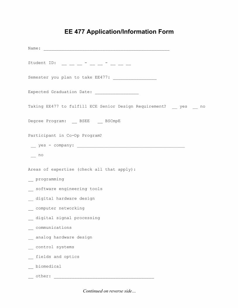
EE 477 Application/Information Form Name: _________________________________________________ Student ID: __ __ __ - __ __ - __ __ __ Semester you plan to take EE477: _________________ Expected Graduation Date: _________________ Taking EE477 to fulfill ECE Senior Design Requirement? __ yes __ no Degree Program: __ BSEE __ BSCmpE Participant in Co-Op Program? __ yes - company: __________________________________________ __ no Areas of expertise (check all that apply): __ programming __ software engineering tools __ digital hardware design __ computer networking __ digital signal processing __ communications __ analog hardware design __ control systems __ fields and optics __ biomedical __ other: _______________________________________
Continued on reverse side…

Do you wish to self-select your teammates or be assigned to a team? __ self-select __ be assigned to a team If you wish to self-select your teammates, list the names of the individuals with whom you would like to work (who are also planning to take EE477 the same semester as you): ______________________________________________________________________ ______________________________________________________________________ ______________________________________________________________________ Do you have a project idea in mind, or would you prefer to have a project assigned to you? __ have the following project in mind (be as specific as possible): __________________________________________________________________ __________________________________________________________________ __________________________________________________________________ __ would prefer to have a project assigned to me List the other courses (including those outside ECE) you plan to take concurrently with EE477: ECE: ___________________ Non-ECE: ___________________ ___________________ ___________________ ___________________ ___________________ ___________________ ___________________ List any other known constraints on your time (e.g., employment): ______________________________________________________________________ ______________________________________________________________________ ______________________________________________________________________

Appendix C:
Proposed Evaluation Form

ECE Senior Design Course/Instructor/Lab/TA Evaluation
Directions: Circle the response that best represents your assessment of each criterion.
Major (SA = CmpE, A = EE, U = other) SA A U D SDHours/week outside class (SA = 1-2, A = 3-4, U = 5-6, D = 7-9, SD = 10 or more) SA A U D SDYour current GPA (SA=3.50-4.00, A=3.00-3.49, U=2.50-2.99, D=2.00-2.49, SD=<1.99) SA A U D SD
COURSE (SA=excellent, A=good, U=average, D=marginal, SD=poor)
Significance of design experience SA A U D SDSpecification and clarity of design project requirements SA A U D SDRelevance of design experience to your personal career goals and objectives SA A U D SDRelevance of lecture topics to course objectives and outcomes SA A U D SDQuality and clarity of course documents SA A U D SDClarity of grading standards and methodology SA A U D SDUsefulness of feedback provided on graded materials and peer evaluations SA A U D SDEffectiveness of homework assignments in pacing the design project SA A U D SDClarity and awareness of course outcomes SA A U D SDCourse outcome assessment procedures SA A U D SD
INSTRUCTOR (SA=excellent, A=good, U=average, D=marginal, SD=poor)
Qualifications of instructor SA A U D SDEffort put forth by instructor SA A U D SDInstructional techniques used in classroom presentations SA A U D SDEffectiveness in answering questions SA A U D SDRapport with students SA A U D SDAvailability during scheduled office hours SA A U D SDDedication of instructor to helping students learn and grow as professionals SA A U D SD
LAB (SA=excellent, A=good, U=average, D=marginal, SD=poor)
Quality of lab facility (space, room, furnishings) SA A U D SDAvailability of lab facility SA A U D SDQuality of lab equipment SA A U D SDMaintenance of lab equipment SA A U D SDAdequacy of lab space and equipment for current enrollment SA A U D SDOverall, I would rate this lab as: SA A U D SD
T.A. (SA=excellent, A=good, U=average, D=marginal, SD=poor)
Qualifications of T.A. SA A U D SDEffort put forth by T.A. SA A U D SDQuality of assistance provided SA A U D SDRapport with students SA A U D SDAvailability during scheduled office hours SA A U D SDOverall, I would rate this T.A. as: SA A U D SD
UNIVERSITY CORE: Overall, I would rate this instructor as: ___ Excellent ___ Good ___ Fair ___ Poor ___ Very Poor Overall, I would rate this course as: ___ Excellent ___ Good ___ Fair ___ Poor ___ Very Poor

Appendix D:
ECE Course Assessment Report

ECE Course Assessment Report Course: EE477 Submitted by: D. G . Meyer Term: Spring 2001 Course PIC: D. G. Meyer 1. Were all course outcomes addressed during the administration of the course? If not, why
not and what actions do you recommend to remedy this problem in future offerings of this course? At the beginning of the course, the following intended outcomes were presented: (i) an ability to apply knowledge obtained in earlier coursework and to obtain new
knowledge necessary to design, build, and test a microcontroller-based digital system (ii) an understanding of the engineering design process (iii) an ability to function on a multidisciplinary team (iv) an awareness of professional and ethical responsibility (v) an ability to communicate effectively, in both oral and written form All of these outcomes were addressed, and all 51 students enrolled during the Spring 2001 offering of EE477 successfully demonstrated each outcome.
2. Are the course outcomes appropriate? Yes.
3. Are the students adequately prepared for this course and are the course prerequisites and co-requisites appropriate? If not, explain.
For the most part, they are adequately prepared – provided they actually remember the prerequisite material covered in EE270 (formerly EE495M or EE266/267) and EE362.
4. Do you have any suggestions for improving this course? If so, explain.
Most problems encountered this semester were a direct result of the 50% over-enrollment that I unwittingly permitted. THIS SHOULD NOT BE ALLOWED TO HAPPEN AGAIN!! The enrollment cap must stay very close to 32 students/8 teams if only one professor and one half-time T.A. are allocated for this course. The primary aspect that could be improved is team formation. One way this could be addressed is through use of an “application form” that students would complete when signing up for the course. Information gathered using this form could be used to formulate teams that are potentially more productive and “balanced”. Another area that could be improved is more rigorous enforcement of “reasonable project goals” – we let a couple groups tackle projects that we suspected were too ambitious for them to complete. In retrospect, we should have forced them to reduce the scope of their projects (instead of just “warn” them).