Embed Size (px)
Citation preview

Proceedings of the World Tunnel Congress 2017 – Large Caverns – Underground solutions. Bergen, Norway.
1
1 INTRODUCTION
1.1 General The Baltic-Adriatic Railway Corridor stretching across Europe connects the Baltic Sea (Gdansk in Poland) and the Adriatic Sea (Bologna in Italy). The more than 27 km long Semmering Base Tunnel will be one of the major structures of the Austrian section of this corridor.
The new tunnel system is located approximately 80 km south of the Austrian capital Vienna, connecting the towns of Gloggnitz in the federal state of Lower Austria and Mürzzuschlag in Styria (see Figure 1.).
The alignment of the existing railway line along this route includes steep gradients and small radii along numerous tunnels and viaducts built in the mid-19th century. Nowadays such conditions are not compatible to modern rail traffic in terms of freight or passenger transports. Heavy cargo trains even require the use of an additional locomotive and the time loss for travels along this stretch is considerably high.
To improve the situation the new tunnels will replace the existing Semmering-Railway line,
which is also a designated world heritage site due to its engineering excellence.
The new tunnel system will reduce the travel time and improve the travel quality for passenger and freight trains crossing the mountainous landscape. The existing Semmering-Railway line will remain in place as a fallback in case of maintenance works in the new tunnels and for local traffic purposes. In addition, due to its breath-taking scenery the old railway line forms an often visited tourist attraction.
The total investment costs for the project are around 3.3 bi. Euros, whereas 1.5 bi. Euros are related to the civil construction works.
Pre-construction works started in 2011 and underground excavation commenced in 2014. All underground excavation works shall be finished by 2022 followed by the installation of the secondary lining, track works, electrical installations and signalling. The envisaged completion date and start for the final operation is 2026.
Semmering Base Tunnel – Large Caverns in Challenging Conditions
M. Proprenter iC consulenten ZT GesmbH, Vienna, Austria.
O. K. Wagner ÖBB - Austrian Federal Railways, Graz, Austria.
ABSTRACT: Semmering Base Tunnel, one of the major infrastructure projects in Europe, consists of two 27.3 km long single-track tunnels, numerous cross passages and a complex underground emergency station with two, more than 420 m deep, shafts. Temporary access is provided by a 1.2 km long access tunnel, with two 120 m subsurface shafts, and two 100 m shafts from the surface. Various types of large caverns are planned, which are either foreseen temporarily for construction purposes such as intermediate access and space for site installations, or permanently for the underground emergency station. The dimensions of the larger caverns are in the range of 25 m by 16 m. The maximum overburden above the caverns is app. 500 m in difficult geological conditions with large fault zones and extensive water inflow, which require complex heading concepts, extensive support measures and partially special ground improvement works such as grouting.
The applied construction method for the caverns and the main part of the single track tubes is SEM/NATM whereas the remaining sections are excavated by means of TBM. Works are ongoing from 2014 until 2026.

Proceedings of the World Tunnel Congress 2017 – Large Caverns – Underground solutions. Bergen, Norway.
2
1.2 Tunnel and Cavern System The final tunnel system with a total length of 27.3 km includes two parallel single track tubes connected by 56 emergency cross passages. The maximum spacing of the cross passages is 500 m.
The centrally located emergency station with various caverns and two, more than 420 m deep, ventilation shafts forms the core of the final tunnel system.
Four additional temporary shafts are required to provide access to the underground construction. Two of the shafts will be excavated, starting underground via a 1.2 km long temporary access tunnel, located around 200 m above the main tunnel alignment. Cavern systems at the heads of the subsurface shafts and at the bases of all shafts accommodate installations and logistics for construction purposes.
The spacing of the mostly parallel running tunnel tubes is around 40 m, which is enlarged at the underground emergency station as well as in massive fault zones and reduced in the portal areas. The alignment of the tunnel is based on a maximum train velocity of 230 km/h with a maximum inclination of 8.4 ‰.
Due to the envisaged completion date and for logistical reasons, the main underground works for the tunnels, shafts and caverns are divided
into three separate construction lots designated SBT 1.1, SBT 2.1 and SBT 3.1 (see Figure 2.).
An additional construction lot is foreseen at the southern portal including the cut and cover and open cut tunnel section with a total length of 650 m as well as the modernization of the adjacent railway station in Mürzzuschlag.
The excavation works for the underground structures are carried out by means of NATM for a total length of 19 km in the northern and southern parts of the tunnels. At the peak of the excavation works a total of up to 12 NATM headings at various locations in the main tunnel tubes will be running at the same time. Due to the geological conditions for about 8 km in the central section of the main tunnel tubes, TBM method is applied. The TBM assembly takes place in the underground caverns located in the emergency station.
In the final tunnels and the permanent caverns a drained secondary lining will be installed. In the northern section of the tunnel, due to legal reasons, mountain water has to be collected below the drainage level and led off separately for further use as drinking water.
Figure 1. General location (source: ÖBB)

Proceedings of the World Tunnel Congress 2017 – Large Caverns – Underground solutions. Bergen, Norway.
3
1.3 General Geology Overall the geological conditions of the tunnel system can be described as an area of intense tectonic imbrication. The main units are the so called Greywacke zone, the Semmering unit and the Wechsel unit.
Within frequently changing conditions rocks consisting of metasediments such as phyllite, schist, quartzite, locally sulphate rocks and metasandstone of various tectonic units as well as carbonate rocks and highly fractured metamorphic crystalline schist and gneiss will be encountered. The geological units are separated by distinct fault zones which formed during the orogenesis with extensive folding and nappe stacking, leading to an imbricate structure. Out of the numerous fault zones the ones consisting of cataclastic fault material with high overburden are especially challenging to the construction procedure. Within the carbonate rock formations a considerable water inflow of up to 300 l/s is expected.
For the design and implementation, the tunnel was divided into 33 rock mass zones, of which more than 40 ground types were evaluated by the geotechnical design team. Rock mass zones can be characterized as tunnel sections, which show similar conditions in terms of geological structure or units, proportions of ground types and hydrogeological conditions. A ground type consists of a rock mass with similar in-situ properties, which refers to a volume of geotechnical relevance for the project.
The sections, which include caverns, are specially designated as individual rock mass zones with their respective ground types considering the enlarged cross sections and mostly differing heading direction.
2 PERMANENT CAVERNS – EMERGENCY
STATION
2.1 Layout In order to fulfil the national and international safety regulations an emergency station is located in the central section of the tunnel system. In case of an accident trains shall stop in the station and passengers shall be transferred to rescue trains approaching via the non-affected tunnel tube.
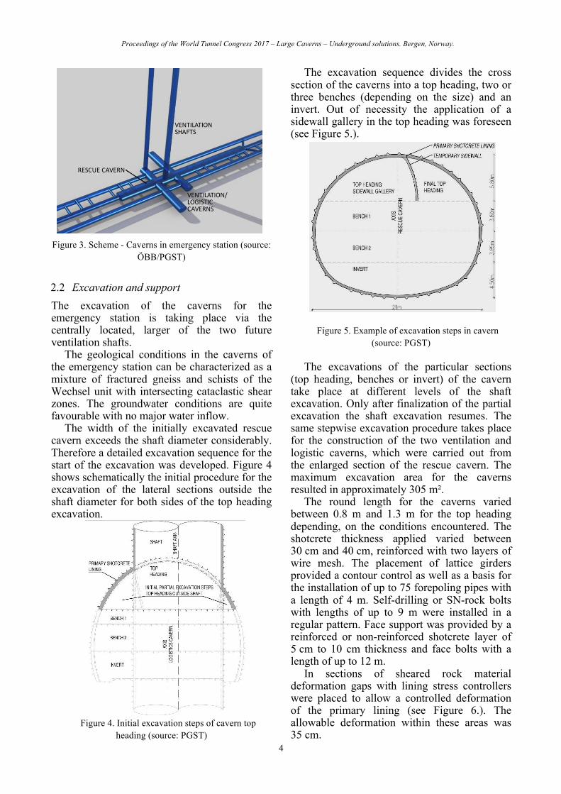
The main structures within the emergency station are two ventilation and logistic caverns and an enlarged section of the rescue tunnel, the so called, rescue cavern. These structures provide space for logistics and underground site installations during the construction phase and will accommodate ventilation, electrical, and safety installations in the final configuration of the emergency station. The maximum size of the caverns is about 20 m by 18 m.
The ventilation and logistic caverns are placed perpendicular to the tunnel alignment, thus stretching over the main tubes and the rescue tunnel. The rescue cavern and tunnel are placed between the running tunnels and connection between the two main tunnel tubes is provided via short escape passages (see Figure 3.).
Additional permanent structures within the emergency station include the two ventilation shafts, the ventilation tunnels between the main tubes and the rescue tunnel, and two regular cross passages.
For a possible material transport by conveyor belts four temporary logistic passages are foreseen, which are aligned accordingly.
Figure 2. General layout including construction lots (source: ÖBB)
Proceedings of the World Tunnel Congress 2017 – Large Caverns – Underground solutions. Bergen, Norway.
4
Figure 3. Scheme - Caverns in emergency station (source: ÖBB/PGST)
2.2 Excavation and support The excavation of the caverns for the emergency station is taking place via the centrally located, larger of the two future ventilation shafts.
The geological conditions in the caverns of the emergency station can be characterized as a mixture of fractured gneiss and schists of the Wechsel unit with intersecting cataclastic shear zones. The groundwater conditions are quite favourable with no major water inflow.
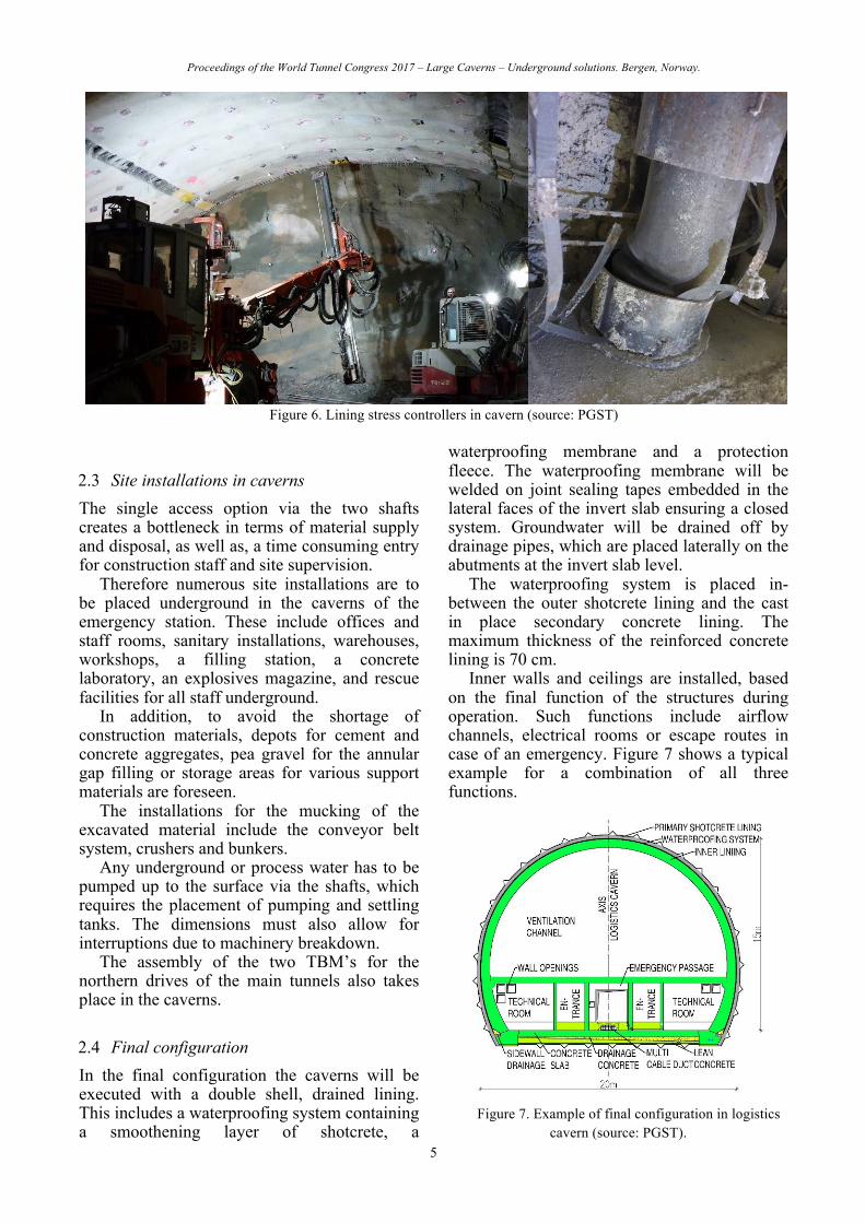
The width of the initially excavated rescue cavern exceeds the shaft diameter considerably. Therefore a detailed excavation sequence for the start of the excavation was developed. Figure 4 shows schematically the initial procedure for the excavation of the lateral sections outside the shaft diameter for both sides of the top heading excavation.
Figure 4. Initial excavation steps of cavern top heading (source: PGST)
The excavation sequence divides the cross section of the caverns into a top heading, two or three benches (depending on the size) and an invert. Out of necessity the application of a sidewall gallery in the top heading was foreseen (see Figure 5.).
Figure 5. Example of excavation steps in cavern (source: PGST)
The excavations of the particular sections
(top heading, benches or invert) of the cavern take place at different levels of the shaft excavation. Only after finalization of the partial excavation the shaft excavation resumes. The same stepwise excavation procedure takes place for the construction of the two ventilation and logistic caverns, which were carried out from the enlarged section of the rescue cavern. The maximum excavation area for the caverns resulted in approximately 305 m².
The round length for the caverns varied between 0.8 m and 1.3 m for the top heading depending, on the conditions encountered. The shotcrete thickness applied varied between 30 cm and 40 cm, reinforced with two layers of wire mesh. The placement of lattice girders provided a contour control as well as a basis for the installation of up to 75 forepoling pipes with a length of 4 m. Self-drilling or SN-rock bolts with lengths of up to 9 m were installed in a regular pattern. Face support was provided by a reinforced or non-reinforced shotcrete layer of 5 cm to 10 cm thickness and face bolts with a length of up to 12 m.
In sections of sheared rock material deformation gaps with lining stress controllers were placed to allow a controlled deformation of the primary lining (see Figure 6.). The allowable deformation within these areas was 35 cm.
Proceedings of the World Tunnel Congress 2017 – Large Caverns – Underground solutions. Bergen, Norway.
5
Figure 6. Lining stress controllers in cavern (source: PGST)
2.3 Site installations in caverns The single access option via the two shafts creates a bottleneck in terms of material supply and disposal, as well as, a time consuming entry for construction staff and site supervision.
Therefore numerous site installations are to be placed underground in the caverns of the emergency station. These include offices and staff rooms, sanitary installations, warehouses, workshops, a filling station, a concrete laboratory, an explosives magazine, and rescue facilities for all staff underground.
In addition, to avoid the shortage of construction materials, depots for cement and concrete aggregates, pea gravel for the annular gap filling or storage areas for various support materials are foreseen.
The installations for the mucking of the excavated material include the conveyor belt system, crushers and bunkers.
Any underground or process water has to be pumped up to the surface via the shafts, which requires the placement of pumping and settling tanks. The dimensions must also allow for interruptions due to machinery breakdown.
The assembly of the two TBM’s for the northern drives of the main tunnels also takes place in the caverns.
2.4 Final configuration In the final configuration the caverns will be executed with a double shell, drained lining. This includes a waterproofing system containing a smoothening layer of shotcrete, a
waterproofing membrane and a protection fleece. The waterproofing membrane will be welded on joint sealing tapes embedded in the lateral faces of the invert slab ensuring a closed system. Groundwater will be drained off by drainage pipes, which are placed laterally on the abutments at the invert slab level.
The waterproofing system is placed in-between the outer shotcrete lining and the cast in place secondary concrete lining. The maximum thickness of the reinforced concrete lining is 70 cm.
Inner walls and ceilings are installed, based on the final function of the structures during operation. Such functions include airflow channels, electrical rooms or escape routes in case of an emergency. Figure 7 shows a typical example for a combination of all three functions.
Figure 7. Example of final configuration in logistics cavern (source: PGST).

Proceedings of the World Tunnel Congress 2017 – Large Caverns – Underground solutions. Bergen, Norway.
6
Figure 8. Cavern intersections at top heading level (source: ÖBB)
Figure 8 shows the intersection of the logistics cavern with the access shaft as well as the intersection with the rescue cavern at the time of the top heading excavation.
3 TEMPORARY CAVERNS
3.1 Layout Complex cavern systems are planned at the shaft bases of the temporary shafts and the top of the subsurface shafts of the northern and southern part of the tunnel. These caverns shall provide space for site installations as well as transport logistics.
In the northern construction lot the cavern system at the shaft head of the subsurface shafts shall accommodate the hoisting system for the material transport as well as the transition from the vertical into the horizontal mucking direction. Therefore the caverns, tunnels and support adits are designed in a two level configuration (see Figure 9.).
Both caverns at the shaft base are placed perpendicular to the main tunnel tubes and are extended in length as to maximize the area available for site installations and material handling. The maximum size of the cavern at the shaft head is in the range of 25 m by 16 m and 19 m by 14 m at the toe of the shaft.
The caverns are connected by two additional cross connections at the ends (see Figure 9.), which enables more options in terms of unidirectional logistics traffic during construction.
Figure 9. Scheme - Final cavern configuration subsurface shafts (source: ÖBB/PGST).
The main logistics cavern is located
perpendicular to the running tunnels at the bottom of the surface access shafts in the southern construction lot. In order to optimize the underground transport routes during construction two additional cross connections are provided (see Figure 10.) on both sides of the main cavern. The dimensions of the cavern are in the range of 13 m by 14.5 m.

Proceedings of the World Tunnel Congress 2017 – Large Caverns – Underground solutions. Bergen, Norway.
7
Figure 10. Scheme - Final cavern configuration surface shafts (source: ÖBB/PGST).
3.2 Excavation and support The cavern excavation takes place via the access tunnel in the case of the shaft head caverns and the access shafts for all other caverns.
The excavation sequences equal in general the procedure described in chapter 2.2 for the permanent caverns. The required grouting measures ahead of the cavern excavation are detailed in chapter 3.3.
The maximum round length for the various support classes is limited to 1.7 m. Support measures include reinforced shotcrete of up to 35 cm thickness, lattice girders, rock bolts with a maximum length of 9 m and forepoling pipes. The maximum excavation area is in the range of 300 m² to 350 m².
3.3 Grouting measures At the toe of the two surface shafts in the southern construction lot, crystalline gneiss with a potential to a complete loss of material strength and subsequent inflow of the water material mix will be encountered. In order to overcome these sections extensive grouting measures for the improvement of the ground conditions in the entire cavern are foreseen. The target is a grouted ring surrounding the excavation boundaries of the underground structures with a minimum thickness of 3 m.
For the evaluation of the most favourable grouting method extensive tests in differing underground conditions were carried out. Various parameters such as type of grouting material (cement or polymer based grout), admixture values or pumping pressure and rate
in differing depths and geological conditions were tested. In case of necessity the grouting process will be carried out in a staggered pattern, starting with cement based grout followed by chemical grouting.
The drilling pattern around the excavation profiles is defined in detail in order to create the envisaged grouting body and volume. Due to the existing ground water level all drillings are to be carried out under the protection of blowout preventers.
3.4 Backfilling The temporary caverns will be backfilled after the finalization of the construction works. Only in case of the placement of a regular cross passage for emergency reasons, parts of the caverns will be used permanently. In addition, some of the caverns will be kept accessible temporarily for the duration of the final installation works such as track works or signalling and will be closed at a later stage.
The backfilling procedure is foreseen as to limit the impact onto the construction works and to hand over certain sections of the tunnel system as soon as possible to the following contracts. In addition, the access via the shafts, or at least one shaft at each access point, shall remain in place as long as possible. Therefore, a stepwise backfilling sequence with the construction of supporting concrete abutments, walls and ceilings was already defined in detail at the tender stage.
The material to be used for the backfilling consists of rock with defined geotechnical characteristics and pea gravel for the upper parts of the cross sections. The pea gravel will be blown in as to guarantee a complete filling of all cavities.
Figure 11. Detail of cavern backfilling at main tube (source: PGST).

Proceedings of the World Tunnel Congress 2017 – Large Caverns – Underground solutions. Bergen, Norway.
8
Figure 12. Cavern backfilling section and plan (source: PGST).
4 CURRENT STATUS All three underground construction lots are under currently progress and the tender design for the open cut construction lot at the southern portal is under preparation.
At the time of publication of this paper the excavation of the permanent caverns in the emergency station will be finished and the arrangement of the site installations has been started.
The excavation of temporary shaft head caverns at the end of the access tunnel of the northern construction lot is ongoing.
In the southern construction lot the grouting measures and the excavation works for the cavern are under progress.
5 CONCLUSION The construction of various caverns for the execution of the Semmering Base Tunnel is required due to the given circumstances in terms of construction schedules, access options, and available space for site installations and transport logistics. Apart from the northern portal all construction lots are accessible via shafts, from the surface or even sub-surface shafts only.
Permanent caverns, as in the emergency station, as well as temporary caverns are used in order to provide sufficient space for the contractors transport logistics, site installations or material handling facilities.
A quite detailed site arrangement design including truck curvatures or the potential placement of machinery equipment was already necessary at the tender stage to provide possible scenarios for the bidders. Such approach was
taken in order to increase the comparability of the various bids.
Caverns with excavation areas exceeding 350 m² are to be built in challenging geological conditions. The positions of the shafts are fixed due to land acquisition and access options. Therefore no major deviations of the foreseen locations of the caverns are possible, which led to extensive support measures and pre-treatment of the underground such as grouting.
ACKNOWLEDGEMENTS
The authors would like to express their great appreciation to all personnel of the client ÖBB and the design joint venture PGST, consisting of the consultants iC consulenten ZT GesmbH, IGT Geotechnik und Tunnelbau ZT GesmbH, Viglconsult and Amberg Engineering AG in-volved in the development of the project for an always constructive and cooperative collabora-tion.
REFERENCES
Wagner, O.K., Gobiet, G., Druckfeuchter, H. 2016. Semmering Base Tunnel completely under construction. Geomechanics and Tunnelling 9 (2016):382–390.
Wagner, O.K., Haas, D., Druckfeuchter, H., Schachinger, T. 2015. The challenges of contract SBT1.1 „Tunnel Gloggnitz“. Geomechanics and Tunnelling 8 (2015):554–567.
Klais, F., Wagner, O.K., Proprenter, M., Wolf, P. 2015. Particular aspects of the tendering contract SBT3.1 „Tunnel Grautschenhof“. Geomechanics and Tunnelling 8 (2015):568–580.

Proceedings of the World Tunnel Congress 2017 – Large Caverns – Underground solutions. Bergen, Norway.
9
Gobiet, G., Wagner, O.K. 2013. The New Semmering Base Tunnel project. Geomechanics and Tunnelling 6 (2013):551–558.


![Alabaster Caverns[1]](https://img.pdfslide.us/doc/110x75/577cc1eb1a28aba7119403cd/alabaster-caverns1.jpg)