Embed Size (px)
Citation preview
SEMI E84-0301 © SEMI 1999, 20011
SEMI E84-0301SPECIFICATION FOR ENHANCED CARRIER HANDOFF PARALLEL I/OINTERFACE
This specification was technically approved by the Global Physical Interfaces & Carriers Committee and isthe direct responsibility of the North American Physical Interfaces & Carriers Committee. Current editionapproved by the North American Regional Standards Committee on November 22, 2000. Initially availableat www.semi.org December 2000; to be published March 2001. Originally published June 1999; previouslypublished October 2000.
1 Purpose1.1 Due to the migration to large wafer sizes, futuresemiconductor factories will use extensive automatedmaterial handling systems (AMHS) to transfer wafercarriers, including FOUPs and open cassettes, ofincreasing weight. The parallel input/output (PI/O)control signals between the production equipment andthe AMHS must be better defined for more reliable andefficient carrier handoffs (load/unload) at productionequipment load ports.
1.2 The purpose of this specification is to enhance thecapabilities of the parallel I/O interface defined inSEMI E23 in order to support improvements in thereliability and efficiency of carrier transfer. Theenhanced capabilities include continuous handoff,simultaneous handoff, and the capabilities of errordetection on the interface.NOTE 1: The specifications in this document shall beconsidered independent from the specifications in SEMI E23;therefore, use of this specification does not require SEMIE23.
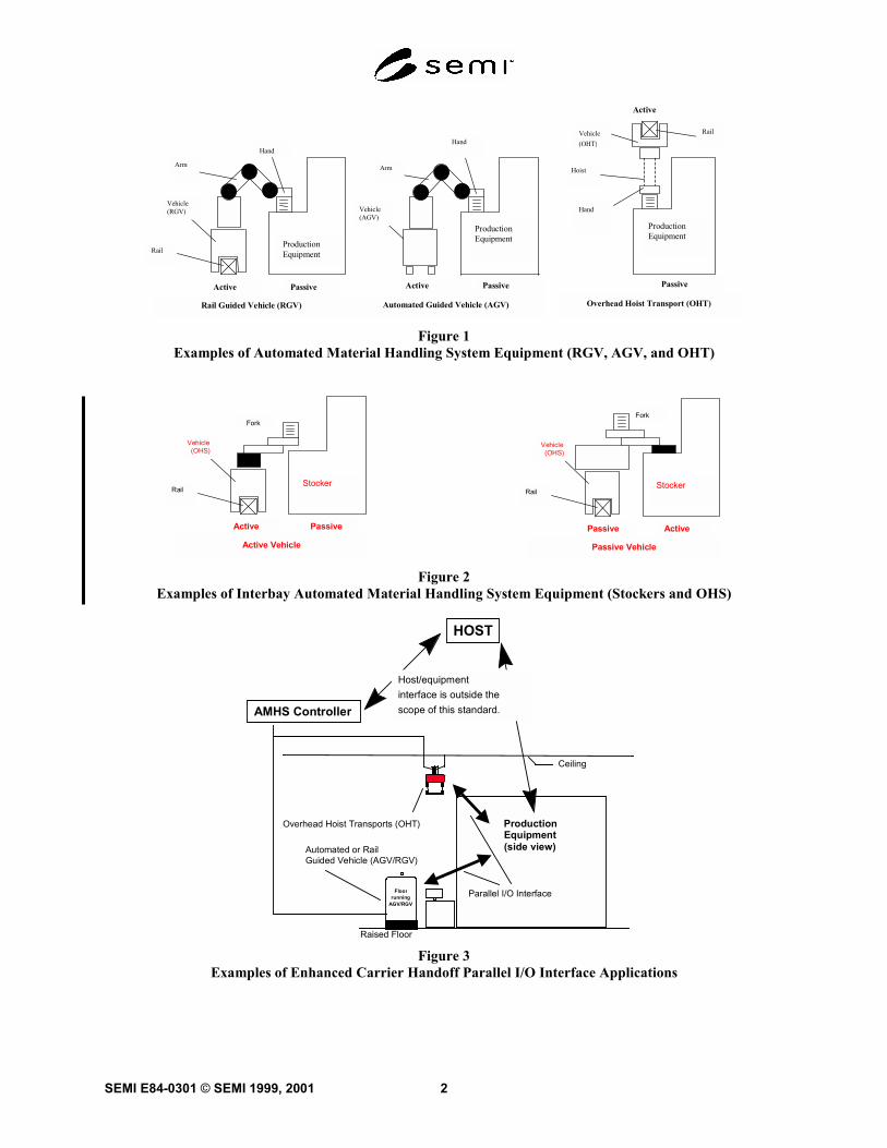
2 Scope2.1 The scope of this specification is limited tocommunications associated with the material handoffoperations between the active equipment (for example,AMHS equipment including AGV, RGV and OHT) andthe passive equipment (for example, productionequipment including process and metrology equipment;stockers, etc). This scope also extends to interbayAMHS active equipment (i.e., OHS and stockersequipped with transfer devices) and passive equipment(i.e., OHS and stockers not equipped with transferdevices). This specification defines the enhancedparallel I/O interface signals used to handoff carriersbetween the production equipment and the AMHS.Figures 1 and 2 show examples of types of AMHSequipment.
2.2 This enhanced carrier handoff parallel I/Ointerface specification includes:
• Signal definition including load port assignmentsignals (see Section 6.1),
• Carrier handoff sequence definitions and timediagrams (see Section 6.2),
• Error indication, detection, and recovery (seeSections 6.3 and 6.4),
• Connector type, signal, and pin assignment (seeSection 6.4), and
• Interface sensor unit size to be located at load portdefined by SEMI E15.1 (applicable for systemsdesigned to handle 300 mm wafer carriers).
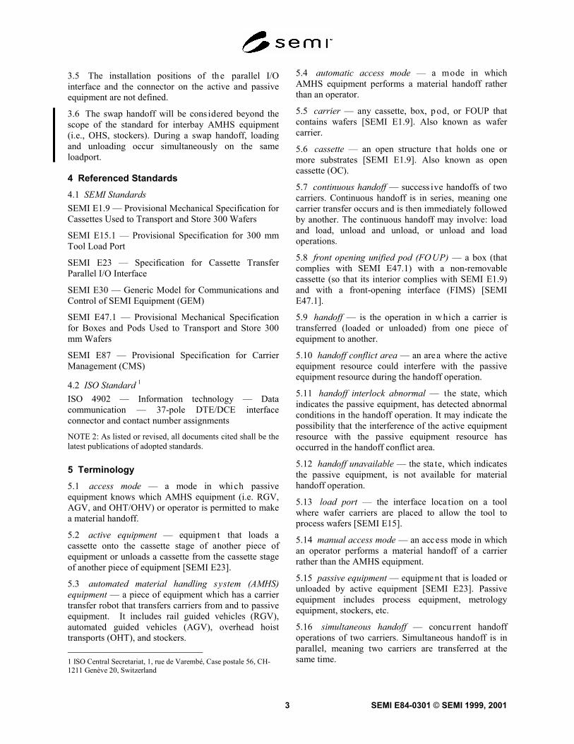
2.3 The enhanced carrier handoff parallel I/O interfacecontrols the handoff of a carrier to and from the passiveequipment by the active equipment. This parallel I/Ointerface only controls the automated handoff operationof the carrier. The handoff is the operation in which acarrier is transferred from one piece of equipment toanother. Both the active and passive equipment managethis operation. The factory level controller (i.e., host)does not manage the handoff operation. Figure 3 showsapplications for the parallel I/O interface specified inthis document.
2.4 This standard does not purport to address safetyissues, if any, associated with its use. It is theresponsibility of the users of this standard to establishappropriate safety and health practices and determinethe applicability of regulatory limitations prior to use.
3 Limitations3.1 Data for the material that is transferred (handedoff) is managed through the equipment’s factoryinterface. Material management by the factory levelcontroller is outside the scope of this document.
3.2 This specification defines the s ignals used to selecta load port. The physical correspondence of the parallelI/O interface to the load port is not defined in thisdocument.
3.3 Error recovery procedures may need operatorassistance and/or proprietary procedures specific to theequipment. Therefore, error recovery procedures are notdefined in this document.
3.4 Signal time diagrams apply to only one parallelI/O interface.
SEMI E84-0301 © SEMI 1999, 2001 2
Rail
Hand
Arm
Vehicle(RGV)
Active Passive
Rail Guided Vehicle (RGV)
ProductionEquipment
ProductionEquipment
Vehicle(AGV)
Arm
Hand
Active Passive
Automated Guided Vehicle (AGV)
Hoist
Active
Vehicle(OHT)
Rail
Hand
ProductionEquipment
Overhead Hoist Transport (OHT)
Passive
Figure 1Examples of Automated Material Handling System Equipment (RGV, AGV, and OHT)
Rail
Fork
Vehicle (OHS)
Active Passive
Active Vehicle
StockerRail
Fork
Vehicle (OHS)
Passive Active
Passive Vehicle
Stocker
Figure 2Examples of Interbay Automated Material Handling System Equipment (Stockers and OHS)
Ceiling
Raised Floor
ProductionEquipment(side view)
Floorrunning
AGV/RGV
Automated or RailGuided Vehicle (AGV/RGV)
AMHS Controller
HOST
Host/equipmentinterface is outside thescope of this standard.
Overhead Hoist Transports (OHT)
Parallel I/O Interface
Figure 3Examples of Enhanced Carrier Handoff Parallel I/O Interface Applications
SEMI E84-0301 © SEMI 1999, 20013
3.5 The installation positions of the parallel I/Ointerface and the connector on the active and passiveequipment are not defined.
3.6 The swap handoff will be cons idered beyond thescope of the standard for interbay AMHS equipment(i.e., OHS, stockers). During a swap handoff, loadingand unloading occur simultaneously on the sameloadport.
4 Referenced Standards4.1 SEMI StandardsSEMI E1.9 — Provisional Mechanical Specification forCassettes Used to Transport and Store 300 Wafers
SEMI E15.1 — Provisional Specification for 300 mmTool Load Port
SEMI E23 — Specification for Cassette TransferParallel I/O Interface
SEMI E30 — Generic Model for Communications andControl of SEMI Equipment (GEM)
SEMI E47.1 — Provisional Mechanical Specificationfor Boxes and Pods Used to Transport and Store 300mm Wafers
SEMI E87 — Provisional Specification for CarrierManagement (CMS)
4.2 ISO Standard 1
ISO 4902 — Information technology — Datacommunication — 37-pole DTE/DCE interfaceconnector and contact number assignments
NOTE 2: As listed or revised, all documents cited shall be thelatest publications of adopted standards.
5 Terminology5.1 access mode — a mode in which passiveequipment knows which AMHS equipment (i.e. RGV,AGV, and OHT/OHV) or operator is permitted to makea material handoff.
5.2 active equipment — equipmen t that loads acassette onto the cassette stage of another piece ofequipment or unloads a cassette from the cassette stageof another piece of equipment [SEMI E23].
5.3 automated material handling system (AMHS)equipment — a piece of equipment which has a carriertransfer robot that transfers carriers from and to passiveequipment. It includes rail guided vehicles (RGV),automated guided vehicles (AGV), overhead hoisttransports (OHT), and stockers. 1 ISO Central Secretariat, 1, rue de Varembé, Case postale 56, CH-1211 Genève 20, Switzerland
5.4 automatic access mode — a mode in whichAMHS equipment performs a material handoff ratherthan an operator.
5.5 carrier — any cassette, box, p od, or FOUP thatcontains wafers [SEMI E1.9]. Also known as wafercarrier.
5.6 cassette — an open structure that holds one ormore substrates [SEMI E1.9]. Also known as opencassette (OC).
5.7 continuous handoff — success ive handoffs of twocarriers. Continuous handoff is in series, meaning onecarrier transfer occurs and is then immediately followedby another. The continuous handoff may involve: loadand load, unload and unload, or unload and loadoperations.
5.8 front opening unified pod (FOUP) — a box (thatcomplies with SEMI E47.1) with a non-removablecassette (so that its interior complies with SEMI E1.9)and with a front-opening interface (FIMS) [SEMIE47.1].
5.9 handoff — is the operation in which a carrier istransferred (loaded or unloaded) from one piece ofequipment to another.
5.10 handoff conflict area — an area where the activeequipment resource could interfere with the passiveequipment resource during the handoff operation.
5.11 handoff interlock abnormal — the state, whichindicates the passive equipment, has detected abnormalconditions in the handoff operation. It may indicate thepossibility that the interference of the active equipmentresource with the passive equipment resource hasoccurred in the handoff conflict area.
5.12 handoff unavailable — the sta te, which indicatesthe passive equipment, is not available for materialhandoff operation.
5.13 load port — the interface loca tion on a toolwhere wafer carriers are placed to allow the tool toprocess wafers [SEMI E15].
5.14 manual access mode — an access mode in whichan operator performs a material handoff of a carrierrather than the AMHS equipment.
5.15 passive equipment — equipment that is loaded orunloaded by active equipment [SEMI E23]. Passiveequipment includes process equipment, metrologyequipment, stockers, etc.
5.16 simultaneous handoff — concurrent handoffoperations of two carriers. Simultaneous handoff is inparallel, meaning two carriers are transferred at thesame time.
SEMI E84-0301 © SEMI 1999, 2001 4
5.17 single arm/double hand AMHS equipment —AMHS equipment which hands off two carriers using asingle arm mechanism with two hands (dual endeffectors).
5.18 single arm/single hand AMHS equipment —AMHS equipment which hands off a carrier using asingle arm mechanism with a single hand (single endeffector).
5.19 single handoff — the transfer o f a single carrierin a handoff operation.
6 Enhanced Carrier Handof f Parallel I/OInterface Requirements6.1 Signal Definitions
6.1.1 Table 1 shows the signals requ ired for theenhanced carrier handoff parallel I/O interface. Thetable defines signal name, the direction of theinformation (P/A: P represents passive equipment andA represents active equipment), and the description. Inthe description, the meaning of the signal and theindication of the signal level, and comments. Signalsdefined in Table 1 are:
VALID Indicates that the signal transition isactive and selected.
CS_0 Carrier Stage 0
CS_1 Carrier Stage 1
TR_REQ Transfer Request
L_REQ Load Request
U_REQ Unload Request
READY READY for Transfer
BUSY BUSY for Transfer
COMPT Complete Transfer
CONT Continuous Handoff
HO_AVBL Handoff Available
ES Emergency Stop
VA Vehicle arrived ∗
AM_AVBL Transfer Arm Available ∗
VS_0 Carrier Stage 0 from Passive OHSVehicle ∗
VS_1 Carrier Stage 1 from Passive OHSVehicle ∗
∗ The VA, AM_AVBL, VS_0,1 signals are intendedonly for use with interbay AMHS equipment (passiveOHS vehicles).
The VALID, CS_0, CS_1 signals are not intended foruse with interbay AMHS equipment (passive OHSvehicles).
6.1.2 Load Port Assignment Signals
6.1.2.1 The signals CS_0 and CS_1 are used to selectload ports to be used for the handoff. For the parallelI/O interface which is dedicated to a single load port,the signals must be set:
CS_0 ON
CS_1 OFF
See Figures 4 and 5.
6.1.2.2 The capability to control two load ports by acommon parallel I/O interface is required; therefore, itis assumed in this specification that a common parallelI/O interface can be used to control handoffs of twoload ports.
6.1.2.3 The assignment of the load port is relevantwhen two load ports use a common parallel I/Ointerface. The active equipment shall select the loadport by means of the CS_0 and/or CS_1 signals (seeFigure 6).
CS_0 selects the left hand load port as viewed whenfacing towards the equipment’s load ports.
CS_1 selects the right hand load port as viewed whenfacing towards the equipment’s load ports.
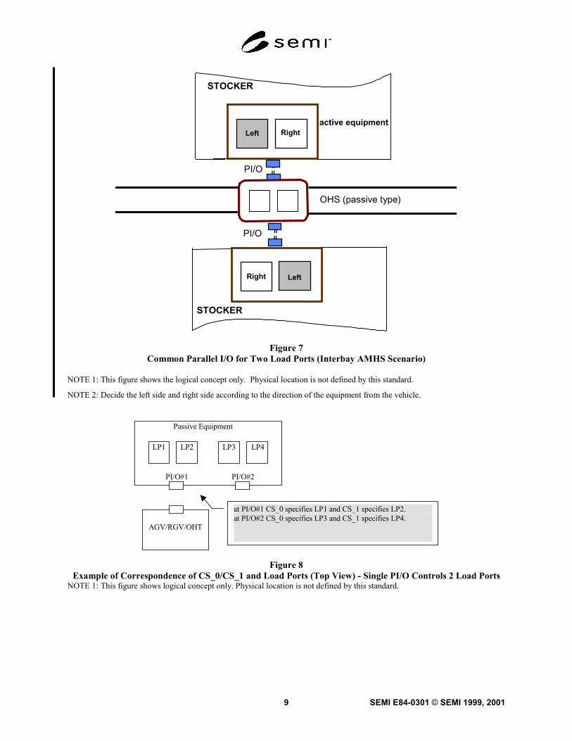
6.1.2.4 For the simultaneous handoff, both of CS_0and CS_1 must be set to ON at the handoff. Figure 8shows a piece of passive equipment with four load ports(LP1, LP2, LP3, LP4) and two parallel I/O interfaces(PI/O#1, PI/O#2), where PI/O#1 is common to loadports LP1 and LP2 and PI/O#2 is common to load portsLP3 and LP4. Tables 2 and 3 show the range of signalcombinations.
6.1.3 Load Port Assignment Signals for OHS (Passivetype)
6.1.3.1 The signals VS_0 and VS_1 are used to selectload ports to be used for the handoff. For the parallelI/O interface which is dedicated to a single load port,the signals must be set;VS_0 ON
VS_1 OFF
6.1.3.2 Two load ports can be controlled by usingVS_0 and VS_1.
VS_0 ON: Selects left hand Load port.
OFF: Does not select Left hand Load port.
SEMI E84-0301 © SEMI 1999, 20015
VS_1 ON: Selects Right hand Load port.
OFF: Does not select Right hand Load port.
VS_0 and VS_1 are controlled individually.
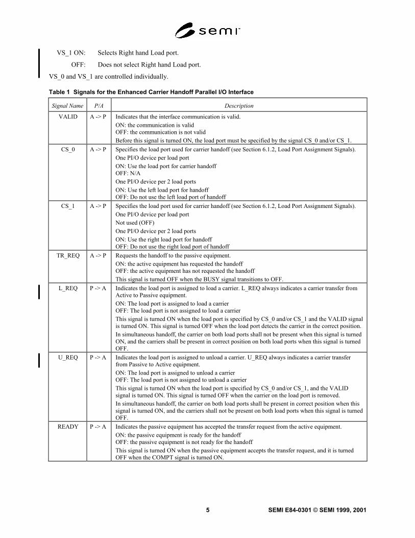
Table 1 Signals for the Enhanced Carrier Handoff Parallel I/O Interface
Signal Name P/A Description
VALID A -> P Indicates that the interface communication is valid.ON: the communication is validOFF: the communication is not validBefore this signal is turned ON, the load port must be specified by the signal CS_0 and/or CS_1.
CS_0 A -> P Specifies the load port used for carrier handoff (see Section 6.1.2, Load Port Assignment Signals).One PI/O device per load portON: Use the load port for carrier handoffOFF: N/AOne PI/O device per 2 load portsON: Use the left load port for handoffOFF: Do not use the left load port of handoff
CS_1 A -> P Specifies the load port used for carrier handoff (see Section 6.1.2, Load Port Assignment Signals).One PI/O device per load portNot used (OFF)One PI/O device per 2 load portsON: Use the right load port for handoffOFF: Do not use the right load port of handoff
TR_REQ A -> P Requests the handoff to the passive equipment.ON: the active equipment has requested the handoffOFF: the active equipment has not requested the handoffThis signal is turned OFF when the BUSY signal transitions to OFF.
L_REQ P -> A Indicates the load port is assigned to load a carrier. L_REQ always indicates a carrier transfer fromActive to Passive equipment.ON: The load port is assigned to load a carrierOFF: The load port is not assigned to load a carrierThis signal is turned ON when the load port is specified by CS_0 and/or CS_1 and the VALID signalis turned ON. This signal is turned OFF when the load port detects the carrier in the correct position.In simultaneous handoff, the carrier on both load ports shall not be present when this signal is turnedON, and the carriers shall be present in correct position on both load ports when this signal is turnedOFF.
U_REQ P -> A Indicates the load port is assigned to unload a carrier. U_REQ always indicates a carrier transferfrom Passive to Active equipment.ON: The load port is assigned to unload a carrierOFF: The load port is not assigned to unload a carrierThis signal is turned ON when the load port is specified by CS_0 and/or CS_1, and the VALIDsignal is turned ON. This signal is turned OFF when the carrier on the load port is removed.In simultaneous handoff, the carrier on both load ports shall be present in correct position when thissignal is turned ON, and the carriers shall not be present on both load ports when this signal is turnedOFF.
READY P -> A Indicates the passive equipment has accepted the transfer request from the active equipment.ON: the passive equipment is ready for the handoffOFF: the passive equipment is not ready for the handoffThis signal is turned ON when the passive equipment accepts the transfer request, and it is turnedOFF when the COMPT signal is turned ON.
SEMI E84-0301 © SEMI 1999, 2001 6
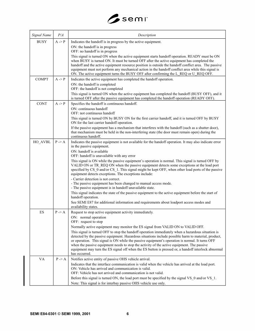
Signal Name P/A Description
BUSY A -> P Indicates the handoff is in progress by the active equipment.ON: the handoff is in progressOFF: no handoff is in progressThis signal is turned ON when the active equipment starts handoff operation. READY must be ONwhen BUSY is turned ON. It must be turned OFF after the active equipment has completed thehandoff and the active equipment resource position is outside the handoff conflict area. The passiveequipment must not perform any mechanical action in the handoff conflict area while this signal isON. The active equipment turns the BUSY OFF after confirming the L_REQ or U_REQ OFF.
COMPT A -> P Indicates the active equipment has completed the handoff operation.ON: the handoff is completedOFF: the handoff is not completedThis signal is turned ON when the active equipment has completed the handoff (BUSY OFF), and itis turned OFF after the passive equipment has completed the handoff operation (READY OFF).
CONT A -> P Specifies the handoff is continuous handoff.ON: continuous handoffOFF: not continuous handoffThis signal is turned ON by BUSY ON for the first carrier handoff, and it is turned OFF by BUSYON for the last carrier handoff operation.If the passive equipment has a mechanism that interferes with the handoff (such as a shutter door),that mechanism must be held in the non-interfering state (the door must remain open) during thecontinuous handoff.
HO_AVBL P -> A Indicates the passive equipment is not available for the handoff operation. It may also indicate errorin the passive equipment.ON: handoff is availableOFF: handoff is unavailable with any errorThis signal is ON while the passive equipment’s operation is normal. This signal is turned OFF byVALID ON or TR_REQ ON when the passive equipment detects some exceptions at the load portspecified by CS_0 and/or CS_1. This signal might be kept OFF, when other load ports of the passiveequipment detects exceptions. The exceptions include:- Carrier detection is not correct.- The passive equipment has been changed to manual access mode.- The passive equipment is in handoff unavailable state.This signal indicates the state of the passive equipment to the active equipment before the start ofhandoff operation.See SEMI E87 for additional information and requirements about loadport access modes andavailability states.
ES P -> A Request to stop active equipment activity immediately.ON: normal operationOFF: request to stopNormally active equipment may monitor the ES signal from VALID ON to VALID OFF.This signal is turned OFF to stop the handoff operation immediately when a hazardous situation isdetected by the passive equipment. Hazardous situations include possible harm to material, product,or operation. This signal is ON while the passive equipment’s operation is normal. It turns OFFwhen the passive equipment needs to stop the activity of the active equipment. The passiveequipment may turn the ES signal off when the ES button is pressed or, a handoff interlock abnormalhas occurred.
VA P -> A Notifies active entity of passive OHS vehicle arrival.Indicates that the interface communication is valid when the vehicle has arrived at the load port.ON: Vehicle has arrived and communication is valid.OFF: Vehicle has not arrived and communication is not valid.Before this signal is turned ON, the load port must be specified by the signal VS_0 and/or VS_1.Note: This signal is for interbay passive OHS vehicle use only.
SEMI E84-0301 © SEMI 1999, 20017
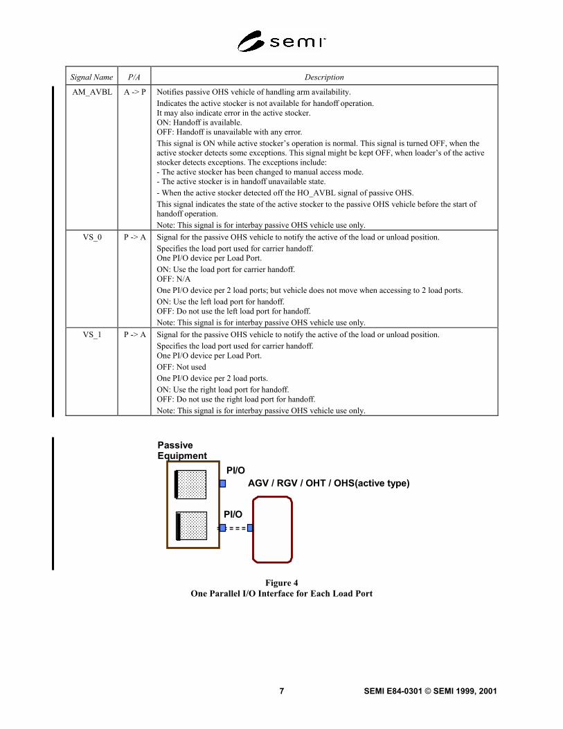
Signal Name P/A Description
AM_AVBL A -> P Notifies passive OHS vehicle of handling arm availability.Indicates the active stocker is not available for handoff operation.It may also indicate error in the active stocker.ON: Handoff is available.OFF: Handoff is unavailable with any error.This signal is ON while active stocker’s operation is normal. This signal is turned OFF, when theactive stocker detects some exceptions. This signal might be kept OFF, when loader’s of the activestocker detects exceptions. The exceptions include:- The active stocker has been changed to manual access mode.- The active stocker is in handoff unavailable state.- When the active stocker detected off the HO_AVBL signal of passive OHS.This signal indicates the state of the active stocker to the passive OHS vehicle before the start ofhandoff operation.Note: This signal is for interbay passive OHS vehicle use only.
VS_0 P -> A Signal for the passive OHS vehicle to notify the active of the load or unload position.Specifies the load port used for carrier handoff.One PI/O device per Load Port.ON: Use the load port for carrier handoff.OFF: N/AOne PI/O device per 2 load ports; but vehicle does not move when accessing to 2 load ports.ON: Use the left load port for handoff.OFF: Do not use the left load port for handoff.Note: This signal is for interbay passive OHS vehicle use only.
VS_1 P -> A Signal for the passive OHS vehicle to notify the active of the load or unload position.Specifies the load port used for carrier handoff.One PI/O device per Load Port.OFF: Not usedOne PI/O device per 2 load ports.ON: Use the right load port for handoff.OFF: Do not use the right load port for handoff.Note: This signal is for interbay passive OHS vehicle use only.
AGV / RGV / OHT / OHS(active type)
Passive Equipment
PI/O
PI/O
Figure 4One Parallel I/O Interface for Each Load Port
SEMI E84-0301 © SEMI 1999, 2001 8
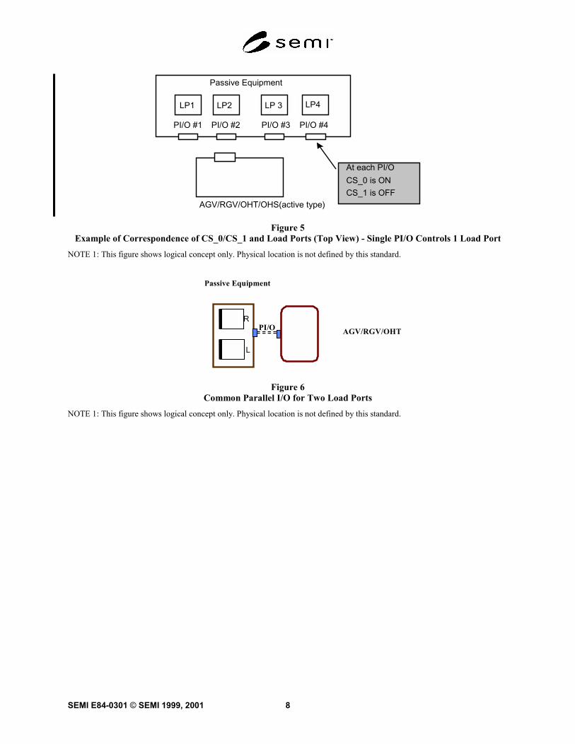
LP4LP 3LP2LP1
Passive Equipment
PI/O #1 PI/O #2 PI/O #3 PI/O #4
AGV/RGV/OHT/OHS(active type)
At each PI/OCS_0 is ONCS_1 is OFF
Figure 5Example of Correspondence of CS_0/CS_1 and Load Ports (Top View) - Single PI/O Controls 1 Load Port
NOTE 1: This figure shows logical concept only. Physical location is not defined by this standard.
Passive Equipment
PI/O AGV/RGV/OHT
L
R
Figure 6Common Parallel I/O for Two Load Ports
NOTE 1: This figure shows logical concept only. Physical location is not defined by this standard.
SEMI E84-0301 © SEMI 1999, 20019
OHS (passive type)
PI/O
PI/O
active equipmentLeft Right
LeftRight
STOCKER
STOCKER
Figure 7Common Parallel I/O for Two Load Ports (Interbay AMHS Scenario)
NOTE 1: This figure shows the logical concept only. Physical location is not defined by this standard.
NOTE 2: Decide the left side and right side according to the direction of the equipment from the vehicle.
LP1 LP3LP2
Passive Equipment
PI/O#1 PI/O#2
LP4
AGV/RGV/OHT
at PI/O#1 CS_0 specifies LP1 and CS_1 specifies LP2.at PI/O#2 CS_0 specifies LP3 and CS_1 specifies LP4.
Figure 8Example of Correspondence of CS_0/CS_1 and Load Ports (Top View) - Single PI/O Controls 2 Load Ports
NOTE 1: This figure shows logical concept only. Physical location is not defined by this standard.
SEMI E84-0301 © SEMI 1999, 2001 10
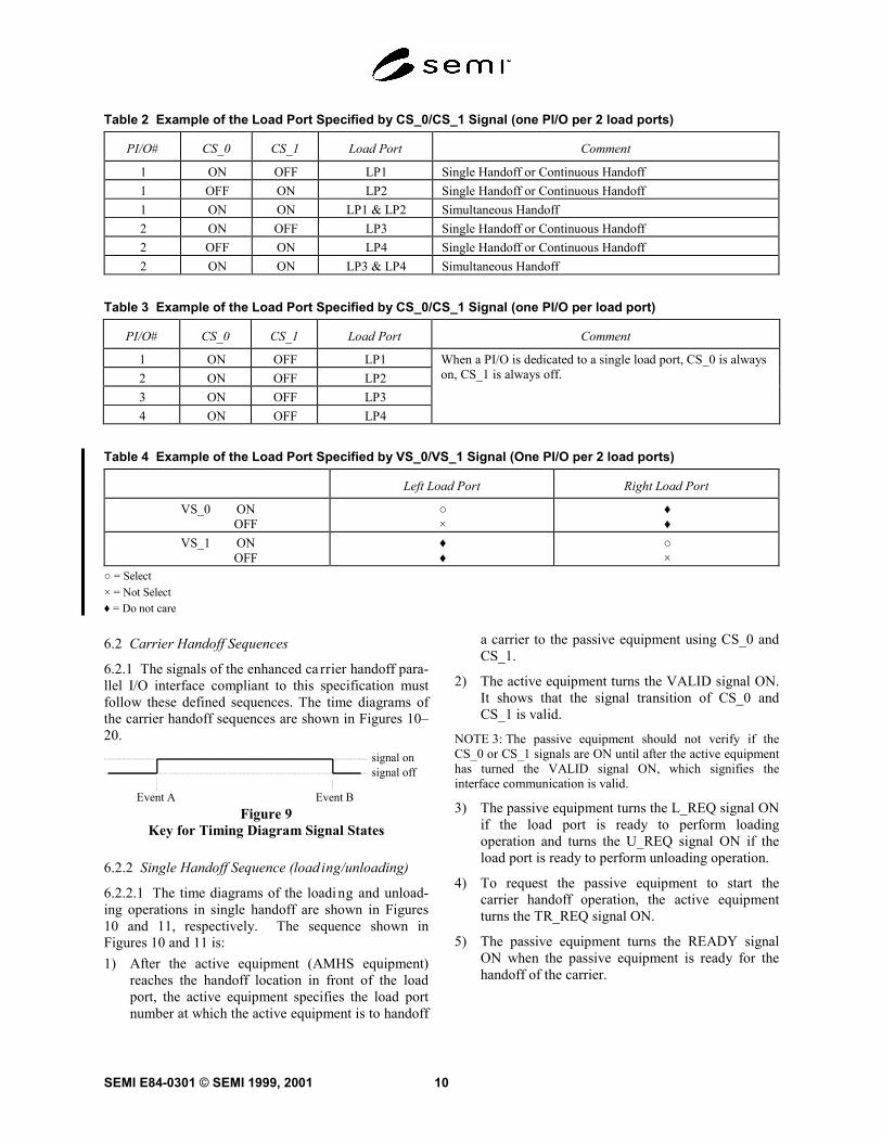
Table 2 Example of the Load Port Specified by CS_0/CS_1 Signal (one PI/O per 2 load ports)
PI/O# CS_0 CS_1 Load Port Comment
1 ON OFF LP1 Single Handoff or Continuous Handoff1 OFF ON LP2 Single Handoff or Continuous Handoff1 ON ON LP1 & LP2 Simultaneous Handoff2 ON OFF LP3 Single Handoff or Continuous Handoff2 OFF ON LP4 Single Handoff or Continuous Handoff2 ON ON LP3 & LP4 Simultaneous Handoff
Table 3 Example of the Load Port Specified by CS_0/CS_1 Signal (one PI/O per load port)
PI/O# CS_0 CS_1 Load Port Comment
1 ON OFF LP12 ON OFF LP23 ON OFF LP34 ON OFF LP4
When a PI/O is dedicated to a single load port, CS_0 is alwayson, CS_1 is always off.
Table 4 Example of the Load Port Specified by VS_0/VS_1 Signal (One PI/O per 2 load ports)
Left Load Port Right Load Port
VS_0 ON OFF
○×
♦♦
VS_1 ON OFF
♦♦
○×
○ = Select× = Not Select♦ = Do not care
6.2 Carrier Handoff Sequences
6.2.1 The signals of the enhanced ca rrier handoff para-llel I/O interface compliant to this specification mustfollow these defined sequences. The time diagrams ofthe carrier handoff sequences are shown in Figures 10–20.
Event A Event B
signal onsignal off
Figure 9Key for Timing Diagram Signal States
6.2.2 Single Handoff Sequence (load ing/unloading)
6.2.2.1 The time diagrams of the loading and unload-ing operations in single handoff are shown in Figures10 and 11, respectively. The sequence shown inFigures 10 and 11 is:1) After the active equipment (AMHS equipment)
reaches the handoff location in front of the loadport, the active equipment specifies the load portnumber at which the active equipment is to handoff
a carrier to the passive equipment using CS_0 andCS_1.
2) The active equipment turns the VALID signal ON.It shows that the signal transition of CS_0 andCS_1 is valid.
NOTE 3: The passive equipment should not verify if theCS_0 or CS_1 signals are ON until after the active equipmenthas turned the VALID signal ON, which signifies theinterface communication is valid.
3) The passive equipment turns the L_REQ signal ONif the load port is ready to perform loadingoperation and turns the U_REQ signal ON if theload port is ready to perform unloading operation.
4) To request the passive equipment to start thecarrier handoff operation, the active equipmentturns the TR_REQ signal ON.
5) The passive equipment turns the READY signalON when the passive equipment is ready for thehandoff of the carrier.
SEMI E84-0301 © SEMI 1999, 200111
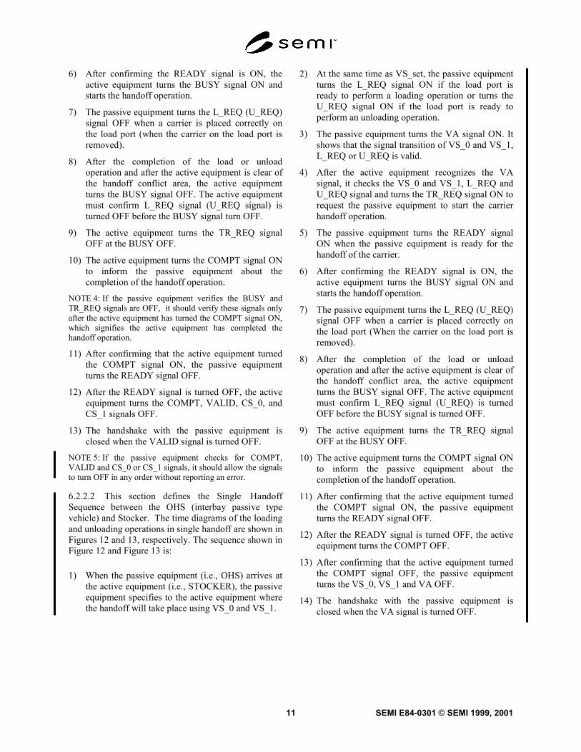
6) After confirming the READY signal is ON, theactive equipment turns the BUSY signal ON andstarts the handoff operation.
7) The passive equipment turns the L_REQ (U_REQ)signal OFF when a carrier is placed correctly onthe load port (when the carrier on the load port isremoved).
8) After the completion of the load or unloadoperation and after the active equipment is clear ofthe handoff conflict area, the active equipmentturns the BUSY signal OFF. The active equipmentmust confirm L_REQ signal (U_REQ signal) isturned OFF before the BUSY signal turn OFF.
9) The active equipment turns the TR_REQ signalOFF at the BUSY OFF.
10) The active equipment turns the COMPT signal ONto inform the passive equipment about thecompletion of the handoff operation.
NOTE 4: If the passive equipment verifies the BUSY andTR_REQ signals are OFF, it should verify these signals onlyafter the active equipment has turned the COMPT signal ON,which signifies the active equipment has completed thehandoff operation.
11) After confirming that the active equipment turnedthe COMPT signal ON, the passive equipmentturns the READY signal OFF.
12) After the READY signal is turned OFF, the activeequipment turns the COMPT, VALID, CS_0, andCS_1 signals OFF.
13) The handshake with the passive equipment isclosed when the VALID signal is turned OFF.
NOTE 5: If the passive equipment checks for COMPT,VALID and CS_0 or CS_1 signals, it should allow the signalsto turn OFF in any order without reporting an error.
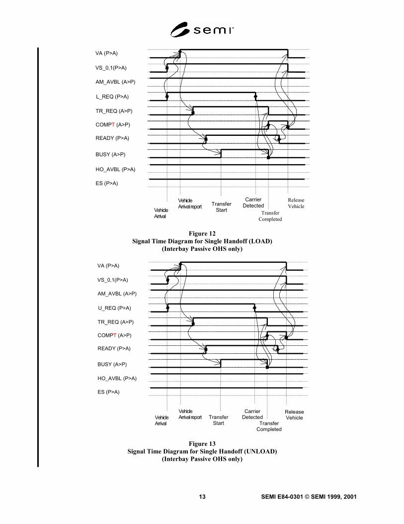
6.2.2.2 This section defines the Single HandoffSequence between the OHS (interbay passive typevehicle) and Stocker. The time diagrams of the loadingand unloading operations in single handoff are shown inFigures 12 and 13, respectively. The sequence shown inFigure 12 and Figure 13 is:
1) When the passive equipment (i.e., OHS) arrives atthe active equipment (i.e., STOCKER), the passiveequipment specifies to the active equipment wherethe handoff will take place using VS_0 and VS_1.
2) At the same time as VS_set, the passive equipmentturns the L_REQ signal ON if the load port isready to perform a loading operation or turns theU_REQ signal ON if the load port is ready toperform an unloading operation.
3) The passive equipment turns the VA signal ON. Itshows that the signal transition of VS_0 and VS_1,L_REQ or U_REQ is valid.
4) After the active equipment recognizes the VAsignal, it checks the VS_0 and VS_1, L_REQ andU_REQ signal and turns the TR_REQ signal ON torequest the passive equipment to start the carrierhandoff operation.
5) The passive equipment turns the READY signalON when the passive equipment is ready for thehandoff of the carrier.
6) After confirming the READY signal is ON, theactive equipment turns the BUSY signal ON andstarts the handoff operation.
7) The passive equipment turns the L_REQ (U_REQ)signal OFF when a carrier is placed correctly onthe load port (When the carrier on the load port isremoved).
8) After the completion of the load or unloadoperation and after the active equipment is clear ofthe handoff conflict area, the active equipmentturns the BUSY signal OFF. The active equipmentmust confirm L_REQ signal (U_REQ) is turnedOFF before the BUSY signal is turned OFF.
9) The active equipment turns the TR_REQ signalOFF at the BUSY OFF.
10) The active equipment turns the COMPT signal ONto inform the passive equipment about thecompletion of the handoff operation.
11) After confirming that the active equipment turnedthe COMPT signal ON, the passive equipmentturns the READY signal OFF.
12) After the READY signal is turned OFF, the activeequipment turns the COMPT OFF.
13) After confirming that the active equipment turnedthe COMPT signal OFF, the passive equipmentturns the VS_0, VS_1 and VA OFF.
14) The handshake with the passive equipment isclosed when the VA signal is turned OFF.
SEMI E84-0301 © SEMI 1999, 2001 12
L_REQ(P -> A)
U_REQ(P -> A)
READY(P -> A)
CS_0(A -> P)
CS_1(A -> P)
VALID(A -> P)
TR_REQ (A -> P)
BUSY(A -> P)
CONT(A -> P)
COMPT (A -> P)
HO_AVBL
(P -> A)
CS isSpecified
TransferStart
Carrier isdetected
Transfer isCompleted
ReleaseCS is
specified
(P -> A)ES
Figure 10Signal Time Diagram for Single Handoff (LOAD)
L_REQ(P -> A)
U_REQ
READY
CS_0
CS_1
VALID
TR_REQ
BUSY
CONT
COMPT
HO_AVBL
CS isSpecified
TransferStart
Carrier isremoved
Transfer isCompleted
ReleaseCS is
specified
ES
(P -> A)
(P -> A)
(A -> P)
(A -> P)
(A -> P)
(A -> P)
(A -> P)
(A -> P)
(A -> P)
(P -> A)
(P -> A)
Figure 11Signal Time Diagram for Single Handoff (UNLOAD)
SEMI E84-0301 © SEMI 1999, 200113
VA (P>A)
VS_0,1(P>A)
AM_AVBL (A>P)
L_REQ (P>A)
TR_REQ (A>P)
COMPT (A>P)
READY (P>A)
BUSY (A>P)
VehicleArrival report Transfer
Start
CarrierDetected
ReleaseVehicle
TransferCompleted
VehicleArrival
HO_AVBL (P>A)
ES (P>A)
Figure 12Signal Time Diagram for Single Handoff (LOAD)
(Interbay Passive OHS only)
VA (P>A)
VS_0,1(P>A)
AM_AVBL (A>P)
U_REQ (P>A)
TR_REQ (A>P)
COMPT (A>P)
READY (P>A)
BUSY (A>P)
TransferStart
CarrierDetected
ReleaseVehicle
TransferCompleted
VehicleArrival
VehicleArrival report
HO_AVBL (P>A)
ES (P>A)
Figure 13Signal Time Diagram for Single Handoff (UNLOAD)
(Interbay Passive OHS only)
SEMI E84-0301 © SEMI 1999, 2001 14
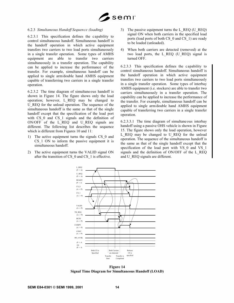
6.2.3 Simultaneous Handoff Sequence (loading)
6.2.3.1 This specification defines the capability tocontrol simultaneous handoff. Simultaneous handoff isthe handoff operation in which active equipmenttransfers two carriers to two load ports simultaneouslyin a single transfer operation. Some types of AMHSequipment are able to transfer two carrierssimultaneously in a transfer operation. The capabilitycan be applied to increase the performance of thetransfer. For example, simultaneous handoff can beapplied to single arm/double hand AMHS equipmentcapable of transferring two carriers in a single transferoperation.
6.2.3.2 The time diagram of simultaneous handoff isshown in Figure 14. The figure shows only the loadoperation; however, L_REQ may be changed toU_REQ for the unload operation. The sequence of thesimultaneous handoff is the same as that of the singlehandoff except that the specification of the load portwith CS_0 and CS_1 signals and the definition ofON/OFF of the L_REQ and U_REQ signals aredifferent. The following list describes the sequencewhich is different from Figures 10 and 11:1) The active equipment turns the signals CS_0 and
CS_1 ON to inform the passive equipment it issimultaneous handoff.
2) The active equipment turns the VALID signal ONafter the transition of CS_0 and CS_1 is effective.
3) The passive equipment turns the L_REQ (U_REQ)signal ON when both carriers in the specified loadports (load ports of both CS_0 and CS_1) are readyto be loaded (unloaded).
4) When both carriers are detected (removed) at thetwo load ports, the L_REQ (U_REQ) signal isturned OFF.
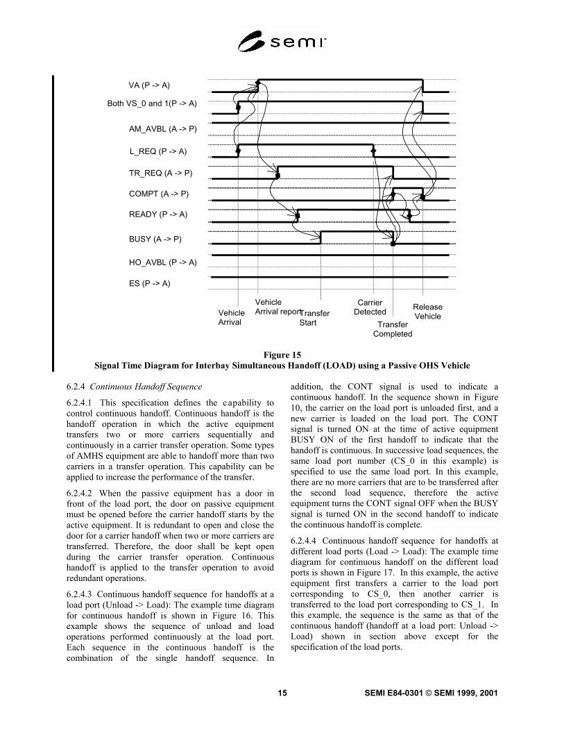
6.2.3.3 This specification defines the capability tocontrol simultaneous handoff. Simultaneous handoff isthe handoff operation in which active equipmenttransfers two carriers to two load ports simultaneouslyin a single transfer operation. Some types of interbayAMHS equipment (i.e. stockers) are able to transfer twocarriers simultaneously in a transfer operation. Thecapability can be applied to increase the performance ofthe transfer. For example, simultaneous handoff can beapplied to single arm/double hand AMHS equipmentcapable of transferring two carriers in a single transferoperation.
6.2.3.3.1 The time diagram of simultaneous interbayhandoff using a passive OHS vehicle is shown in Figure15. The figure shows only the load operation, howeverL_REQ may be changed to U_REQ for the unloadoperation. The sequence of the simultaneous handoff isthe same as that of the single handoff except that thespecification of the load port with VS_0 and VS_1signals and the definition of ON/OFF of the L_REQand U_REQ signals are different.
L_REQ(P -> A)
U_REQ
READY
CS_0(A -> P)
CS_1
VALID
TR_REQ
BUSY
CONT
COMPT
HO_AVBL
Both CS isSpecified
TransferStart
Both Carriersare detected
Transfer isCompleted
ReleaseCS is
specified
ES
(P -> A)
(P -> A
(P -> A
(P -> A
(A -> P)
(A -> P)
(A -> P)
(A -> P)
(A -> P)
(A -> P)
Figure 14Signal Time Diagram for Simultaneous Handoff (LOAD)
SEMI E84-0301 © SEMI 1999, 200115
VA (P -> A)
Both VS_0 and 1(P -> A)
AM_AVBL (A -> P)
L_REQ (P -> A)
TR_REQ (A -> P)
COMPT (A -> P)
READY (P -> A)
BUSY (A -> P)
VehicleArrival reportTransfer
Start
CarrierDetected Release
VehicleTransfer
Completed
VehicleArrival
HO_AVBL (P -> A)
ES (P -> A)
Figure 15Signal Time Diagram for Interbay Simultaneous Handoff (LOAD) using a Passive OHS Vehicle
6.2.4 Continuous Handoff Sequence
6.2.4.1 This specification defines the capability tocontrol continuous handoff. Continuous handoff is thehandoff operation in which the active equipmenttransfers two or more carriers sequentially andcontinuously in a carrier transfer operation. Some typesof AMHS equipment are able to handoff more than twocarriers in a transfer operation. This capability can beapplied to increase the performance of the transfer.
6.2.4.2 When the passive equipment has a door infront of the load port, the door on passive equipmentmust be opened before the carrier handoff starts by theactive equipment. It is redundant to open and close thedoor for a carrier handoff when two or more carriers aretransferred. Therefore, the door shall be kept openduring the carrier transfer operation. Continuoushandoff is applied to the transfer operation to avoidredundant operations.
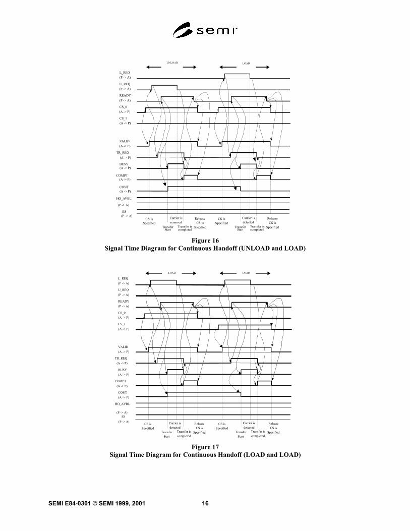
6.2.4.3 Continuous handoff sequence for handoffs at aload port (Unload -> Load): The example time diagramfor continuous handoff is shown in Figure 16. Thisexample shows the sequence of unload and loadoperations performed continuously at the load port.Each sequence in the continuous handoff is thecombination of the single handoff sequence. In
addition, the CONT signal is used to indicate acontinuous handoff. In the sequence shown in Figure10, the carrier on the load port is unloaded first, and anew carrier is loaded on the load port. The CONTsignal is turned ON at the time of active equipmentBUSY ON of the first handoff to indicate that thehandoff is continuous. In successive load sequences, thesame load port number (CS_0 in this example) isspecified to use the same load port. In this example,there are no more carriers that are to be transferred afterthe second load sequence, therefore the activeequipment turns the CONT signal OFF when the BUSYsignal is turned ON in the second handoff to indicatethe continuous handoff is complete.
6.2.4.4 Continuous handoff sequence for handoffs atdifferent load ports (Load -> Load): The example timediagram for continuous handoff on the different loadports is shown in Figure 17. In this example, the activeequipment first transfers a carrier to the load portcorresponding to CS_0, then another carrier istransferred to the load port corresponding to CS_1. Inthis example, the sequence is the same as that of thecontinuous handoff (handoff at a load port: Unload ->Load) shown in section above except for thespecification of the load ports.
SEMI E84-0301 © SEMI 1999, 2001 16
UNLOAD
L_REQ(P -> A)
U_REQ
READY
CS_0
CS_1
VALID
TR_REQ
BUSY
CONT
COMPT
HO_AVBL
LOAD
CS isSpecified
TransferStart
Carrier isdetected
Transfer iscompleted
ReleaseCS is
Specified
CS isSpecified
TransferStart
Carrier isremoved
Transfer iscompleted
ReleaseCS is
Specified
ES
(P -> A)
(P -> A)
(A -> P)
(P -> A)
(P -> A)
(A -> P)
(A -> P)
(A -> P)
(A -> P)
(A -> P)
(A -> P)
Figure 16Signal Time Diagram for Continuous Handoff (UNLOAD and LOAD)
L_REQ(P -> A)
U_REQ(P -> A)
READY(P -> A)
CS_0(A -> P)
CS_1(A -> P)
VALID(A -> P)
TR_REQ (A -> P)
BUSY(A -> P)
CONT(A -> P)
COMPT (A -> P)
HO_AVBL
(P -> A)
LOAD
CS isSpecified
TransferStart
Carrier isdetected
Transfer iscompleted
ReleaseCS is
Specified
CS isSpecified
TransferStart
Carrier isdetected
Transfer iscompleted
ReleaseCS is
Specified
LOAD
(P -> A) ES
Figure 17Signal Time Diagram for Continuous Handoff (LOAD and LOAD)
SEMI E84-0301 © SEMI 1999, 200117
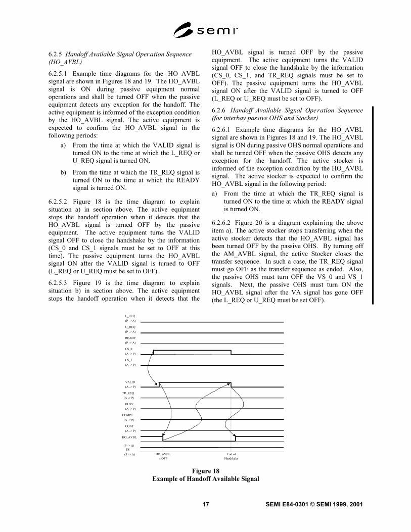
6.2.5 Handoff Available Signal Operation Sequence(HO_AVBL)
6.2.5.1 Example time diagrams for the HO_AVBLsignal are shown in Figures 18 and 19. The HO_AVBLsignal is ON during passive equipment normaloperations and shall be turned OFF when the passiveequipment detects any exception for the handoff. Theactive equipment is informed of the exception conditionby the HO_AVBL signal. The active equipment isexpected to confirm the HO_AVBL signal in thefollowing periods:
a) From the time at which the VALID signal isturned ON to the time at which the L_REQ orU_REQ signal is turned ON.
b) From the time at which the TR_REQ signal isturned ON to the time at which the READYsignal is turned ON.
6.2.5.2 Figure 18 is the time diagram to explainsituation a) in section above. The active equipmentstops the handoff operation when it detects that theHO_AVBL signal is turned OFF by the passiveequipment. The active equipment turns the VALIDsignal OFF to close the handshake by the information(CS_0 and CS_1 signals must be set to OFF at thistime). The passive equipment turns the HO_AVBLsignal ON after the VALID signal is turned to OFF(L_REQ or U_REQ must be set to OFF).
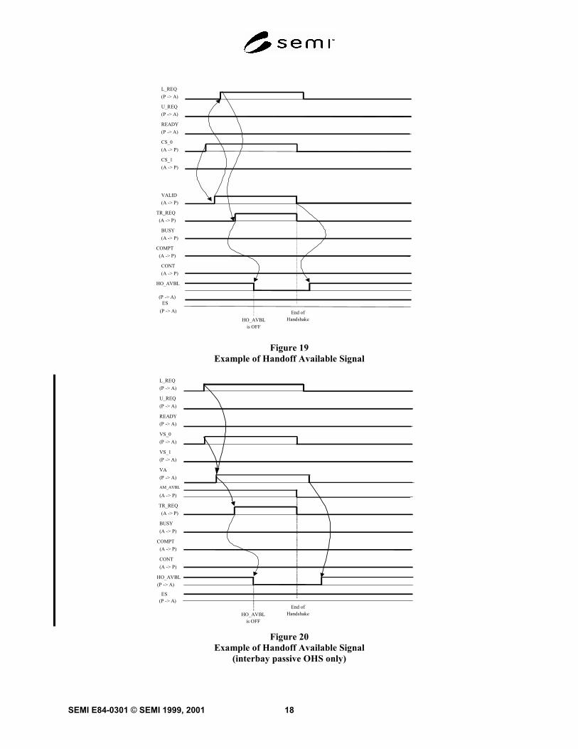
6.2.5.3 Figure 19 is the time diagram to explainsituation b) in section above. The active equipmentstops the handoff operation when it detects that the
HO_AVBL signal is turned OFF by the passiveequipment. The active equipment turns the VALIDsignal OFF to close the handshake by the information(CS_0, CS_1, and TR_REQ signals must be set toOFF). The passive equipment turns the HO_AVBLsignal ON after the VALID signal is turned to OFF(L_REQ or U_REQ must be set to OFF).
6.2.6 Handoff Available Signal Operation Sequence(for interbay passive OHS and Stocker)
6.2.6.1 Example time diagrams for the HO_AVBLsignal are shown in Figures 18 and 19. The HO_AVBLsignal is ON during passive OHS normal operations andshall be turned OFF when the passive OHS detects anyexception for the handoff. The active stocker isinformed of the exception condition by the HO_AVBLsignal. The active stocker is expected to confirm theHO_AVBL signal in the following period:a) From the time at which the TR_REQ signal is
turned ON to the time at which the READY signalis turned ON.
6.2.6.2 Figure 20 is a diagram explain ing the aboveitem a). The active stocker stops transferring when theactive stocker detects that the HO_AVBL signal hasbeen turned OFF by the passive OHS. By turning offthe AM_AVBL signal, the active Stocker closes thetransfer sequence. In such a case, the TR_REQ signalmust go OFF as the transfer sequence as ended. Also,the passive OHS must turn OFF the VS_0 and VS_1signals. Next, the passive OHS must turn ON theHO_AVBL signal after the VA signal has gone OFF(the L_REQ or U_REQ must be set OFF).
L_REQ(P -> A)
U_REQ(P -> A)
READY(P -> A)
CS_0(A -> P)
CS_1(A -> P)
VALID(A -> P)
TR_REQ (A -> P)
BUSY(A -> P)
CONT(A -> P)
COMPT (A -> P)
HO_AVBL
(P -> A)
HO_AVBLis OFF
End ofHandshake
(P -> A)ES
Figure 18Example of Handoff Available Signal
SEMI E84-0301 © SEMI 1999, 2001 18
L_REQ(P -> A)
U_REQ(P -> A)
READY(P -> A)
CS_0(A -> P)
CS_1(A -> P)
VALID(A -> P)
TR_REQ (A -> P)
BUSY(A -> P)
CONT(A -> P)
COMPT (A -> P)
HO_AVBL
(P -> A)
HO_AVBLis OFF
End ofHandshake
(P -> A)ES
Figure 19Example of Handoff Available Signal
L_REQ(P -> A)
U_REQ(P -> A)
READY(P -> A)
VS_0(P -> A)
VS_1(P -> A)
AM_AVBL
(A -> P)
TR_REQ (A -> P)
BUSY(A -> P)
CONT(A -> P)
VA(P -> A)
COMPT (A -> P)
HO_AVBL(P -> A)
HO_AVBLis OFF
End ofHandshake
(P -> A)ES
Figure 20Example of Handoff Available Signal
(interbay passive OHS only)
SEMI E84-0301 © SEMI 1999, 200119
6.3 Error Indication and Detection
6.3.1 Error Indication
6.3.1.1 To support operational reliabil ity, thisspecification will define the following capabilities toindicate errors on the interface:a) inform handoff unavailable which means the
passive equipment (or passive OHS) is notavailable for material handoff operation to theactive equipment.
b) inform emergency stop request to the activeequipment (or active stocker).
c) inform handoff timeout error.
6.3.2 Error Detection
6.3.2.1 Interlock timeouts are required to detecthandoff sequence error between the active and passiveequipment. This specification defines the interlocktimeouts to be monitored by the active equipment andthe passive equipment. Table 5 shows the interlocktimeouts for active equipment. Table 6 shows the
timeouts for the passive equipment. TAx (x is anumber) represents the timer for the active equipment,and TPx (x is a number) represents the timer for thepassive equipment. The range for all timers (exceptTD0) shall be from 1 second to 999 seconds. All timersetpoints shall be user programmable.
6.3.2.2 The delay timer specifies the d elay time be-tween VALID signals of two successive handoffs. Thedelay timer is required because the passive equipmentmay need a certain time margin to detect the secondVALID signal transition to ON. Table 6 shows thedelay timer. All timer setpoints shall be userprogrammable.
6.3.2.3 The recommended and optiona l delay timerTD0 defines the timing between CS_0 or CS_1 ON andVALID ON for the active equipment as shown in thesignal time diagrams. In this way, the passiveequipment can predict the timing in which the activeequipment will output the signal allowing the transferinterlock to be performed accurately.
Table 5 Active Equipment Timer
Timer Name Period (Signal Status) to Monitor the Timer Range (SEC) TYP (SEC)
TA1 VALID ON - L_REQ ONVALID ON - U_REQ ON
1–999 2
TA2 TR_REQ ON - READY ON 1–999 2TA3 COMPT ON - READY OFF 1–999 2
NOTE 1: The minimum timer value does not define the response time of the active equipment.NOTE 2: These timer values must be implemented for detecting timeouts and are not meant to specify the delay time between signals. Theequipment response time must be faster than the timeout of the timer.
Table 6 Passive Equipment Timer
Timer Name Period (Signal Status) to Monitor the Timer Range (SEC) TYP (SEC)
TP1 L_REQ ON - TR_REQ ONU_REQ ON - TR_REQ ON
1–999 2
TP2 READY ON - BUSY ON 1–999 2TP3 BUSY ON - CARRIER DETECT
BUSY ON - CARRIER REMOVE1–999 60
TP4 U_REQ OFF - BUSY OFFL_REQ OFF - BUSY OFF
1–999 60
TP5 READY OFF - VALID OFF 1–999 2TP6 VALID OFF - VALID ON (Continuous handoff) 1–999 2
NOTE 1: The minimum timer value does not define the response time of the passive equipment.NOTE 2: These timer values must be implemented for detecting timeouts and are not meant to specify the delay time between signals. Theequipment response time must be faster than the timeout of the timer.
SEMI E84-0301 © SEMI 1999, 2001 20
Table 7 Delay Timer
Timer Name Period (Signal Status) to Monitor the Timer Range (SEC) TYP (SEC)
TD0 CS ON - VALID ON 0.1–0.2 0.1
TD1 VALID OFF - VALID ON 1–999 1
6.3.3 Error Recovery
6.3.3.1 Error recovery procedures are not defined in this specification. Recovery procedures may require operatorassistance and/or proprietary procedures specific to the equipment. It is recommended that the recovery procedure(ex, abort interlock sequence and set to restart/complete) be provided on the active equipment and the passiveequipment.
6.4 Connector Type, Signal, and Pin Assignment
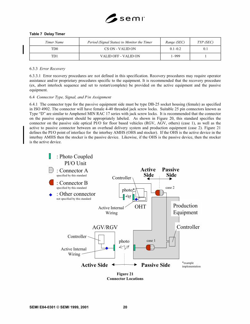
6.4.1 The connector type for the passive equipment side must be type DB-25 socket housing (female) as specifiedin ISO 4902. The connector will have female 4-40 threaded jack screw locks. Suitable 25 pin connectors known asType “D” are similar to Amphenol MIN RAC 17 series with jack screw locks. It is recommended that the connectoron the passive equipment should be appropriately labeled. As shown in Figure 20, this standard specifies theconnector on the passive side optical PI/O for floor based vehicles (RGV, AGV, others) (case 1), as well as theactive to passive connector between an overhead delivery system and production equipment (case 2). Figure 21defines the PI/O point of interface for the interbay AMHS (OHS and stocker). If the OHS is the active device in theinterbay AMHS then the stocker is the passive device. Likewise, if the OHS is the passive device, then the stockeris the active device.
ProductionEquipment
AGV/RGV
OHT
Controller
Controller
Controller
photo
photo*
Passive SideActive Side
Passive Side
Active Side
Active Internal Wiring
Active Internal Wiring
: Photo Coupled PI/O Unit
: Connector Aspecified by this standard
: Connector Bspecified by this standard
: Other connectornot specified by this standard
*exampleimplementation
case 1
case 2
Figure 21Connector Locations
SEMI E84-0301 © SEMI 1999, 200121
Stocker
Controller
Point of Interface: Photo Coupled
PI/O Unit: Connector A
specified by this standard
: Connector Bspecified by this standard
: Other connectornot specified by this standard
Internal WiringOHS
Controller
photo*
* exampleimplementation
Case 3
Case 4
NOTENOTE
NOTE : Connected with Case 3 or Case 4
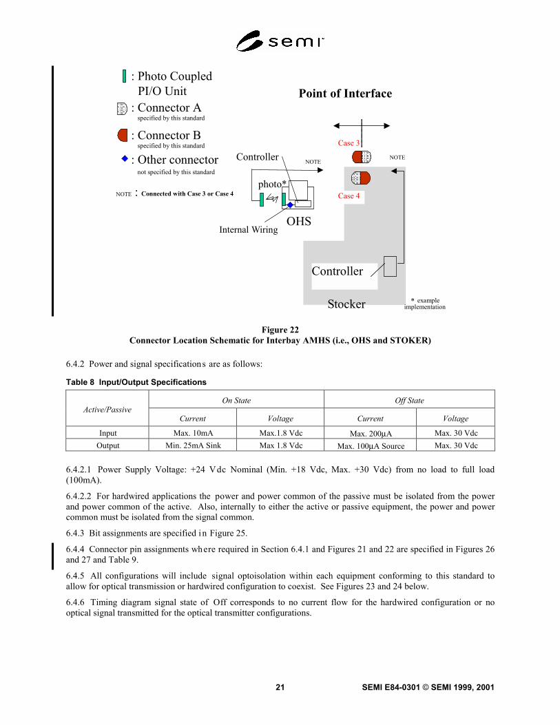
Figure 22Connector Location Schematic for Interbay AMHS (i.e., OHS and STOKER)
6.4.2 Power and signal specifications are as follows:
Table 8 Input/Output Specifications
On State Off StateActive/Passive
Current Voltage Current Voltage
Input Max. 10mA Max.1.8 Vdc Max. 200µA Max. 30 VdcOutput Min. 25mA Sink Max 1.8 Vdc Max. 100µA Source Max. 30 Vdc
6.4.2.1 Power Supply Voltage: +24 Vdc Nominal (Min. +18 Vdc, Max. +30 Vdc) from no load to full load(100mA).
6.4.2.2 For hardwired applications the power and power common of the passive must be isolated from the powerand power common of the active. Also, internally to either the active or passive equipment, the power and powercommon must be isolated from the signal common.
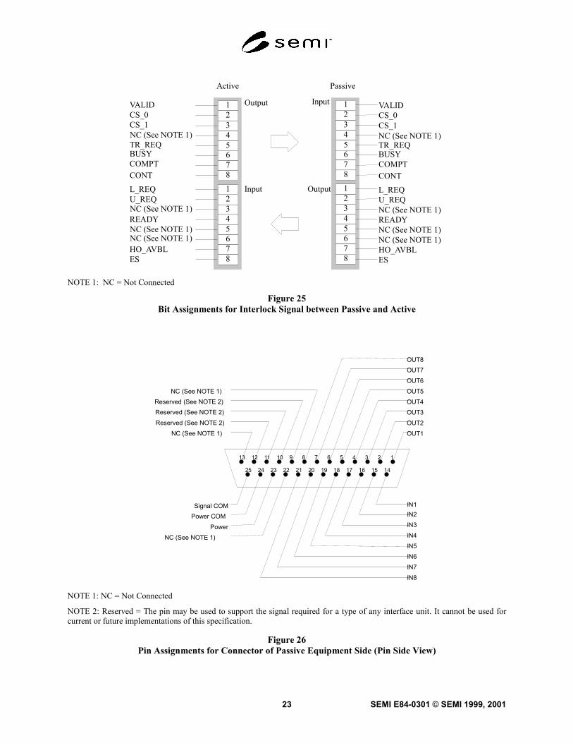
6.4.3 Bit assignments are specified in Figure 25.
6.4.4 Connector pin assignments where required in Section 6.4.1 and Figures 21 and 22 are specified in Figures 26and 27 and Table 9.
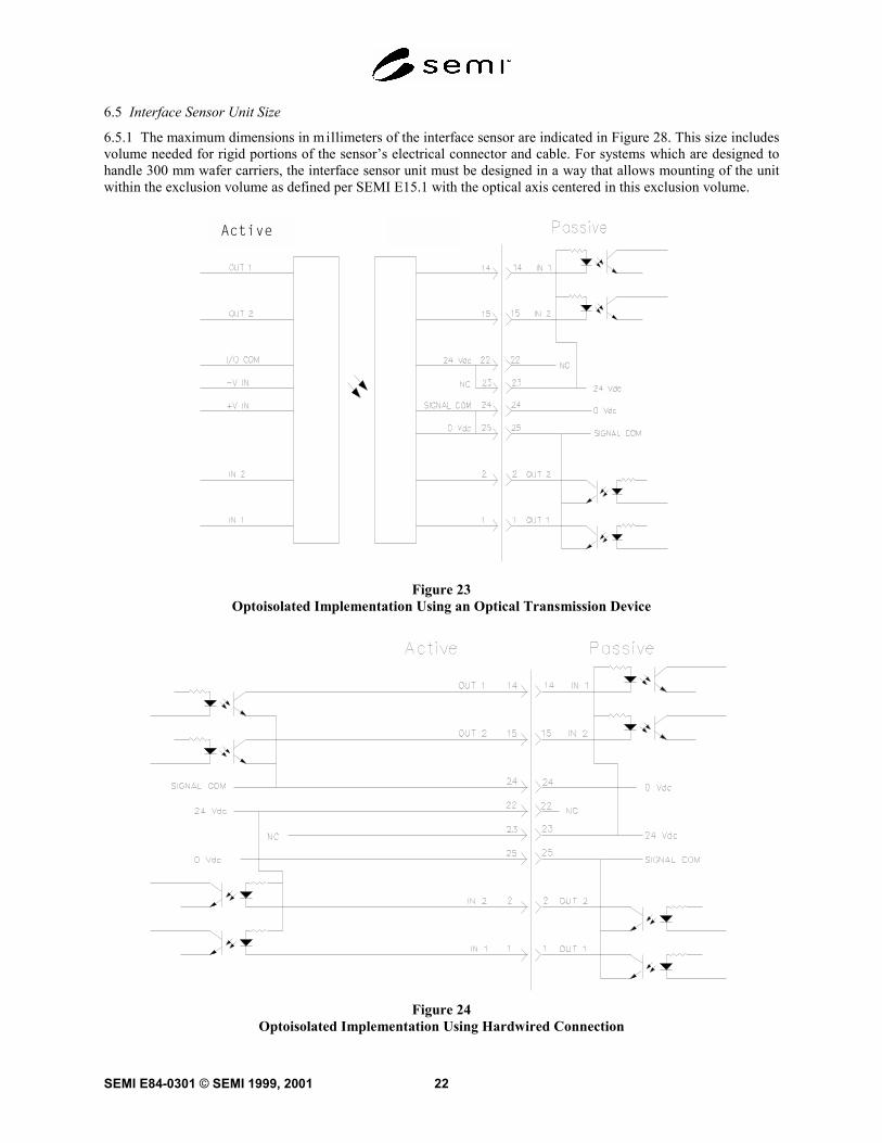
6.4.5 All configurations will include signal optoisolation within each equipment conforming to this standard toallow for optical transmission or hardwired configuration to coexist. See Figures 23 and 24 below.
6.4.6 Timing diagram signal state of Off corresponds to no current flow for the hardwired configuration or nooptical signal transmitted for the optical transmitter configurations.
SEMI E84-0301 © SEMI 1999, 2001 22
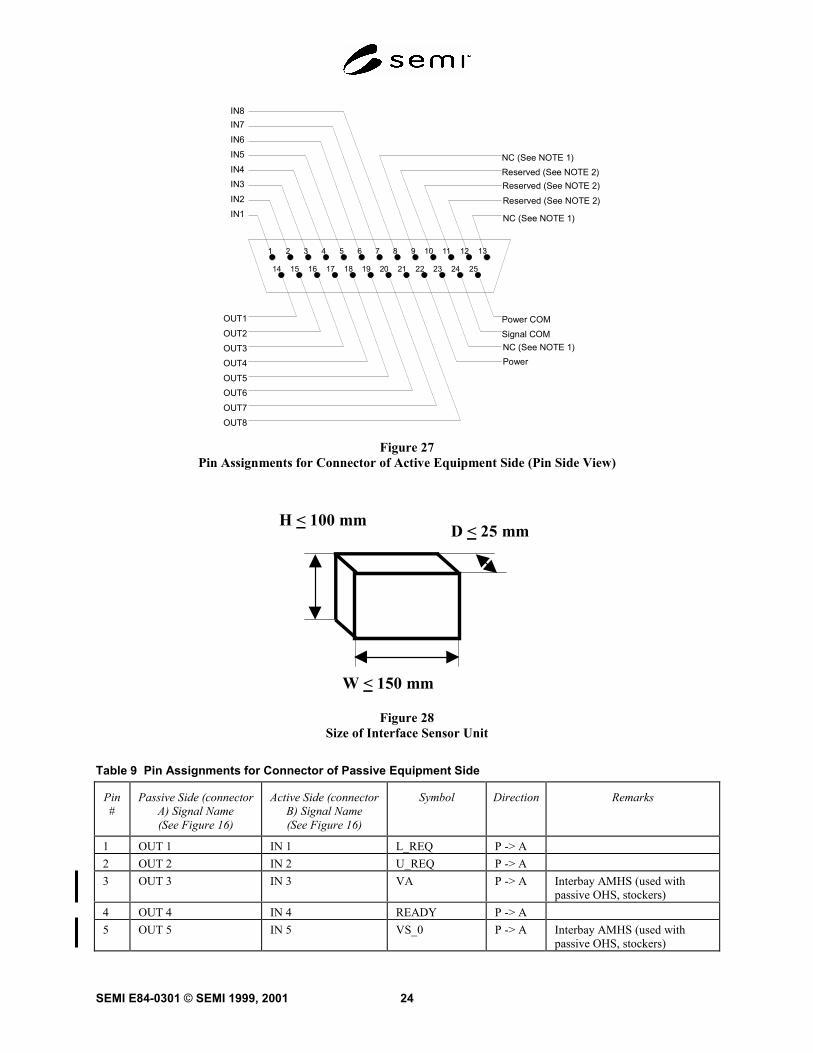
6.5 Interface Sensor Unit Size
6.5.1 The maximum dimensions in millimeters of the interface sensor are indicated in Figure 28. This size includesvolume needed for rigid portions of the sensor’s electrical connector and cable. For systems which are designed tohandle 300 mm wafer carriers, the interface sensor unit must be designed in a way that allows mounting of the unitwithin the exclusion volume as defined per SEMI E15.1 with the optical axis centered in this exclusion volume.
Active
Figure 23Optoisolated Implementation Using an Optical Transmission Device
Figure 24Optoisolated Implementation Using Hardwired Connection
SEMI E84-0301 © SEMI 1999, 200123
Input
Output
Output
Input
VALIDCS_0CS_1NC (See NOTE 1)TR_REQBUSYCOMPTCONT
L_REQU_REQNC (See NOTE 1)READYNC (See NOTE 1)NC (See NOTE 1)HO_AVBLES
345
12
678
2345678
1
345
345
12
678
2345678
1
345
VALIDCS_0CS_1
TR_REQBUSYCOMPTCONT
L_REQU_REQ
READY
HO_AVBLES
Active Passive
NC (See NOTE 1)
NC (See NOTE 1)
NC (See NOTE 1)NC (See NOTE 1)
NOTE 1: NC = Not Connected
Figure 25Bit Assignments for Interlock Signal between Passive and Active
12
141516
345678910111213
171819202122232425
OUT1OUT2OUT3OUT4OUT5OUT6OUT7OUT8
NC (See NOTE 1)Reserved (See NOTE 2)Reserved (See NOTE 2)Reserved (See NOTE 2)
NC (See NOTE 1)
Signal COMPower COM
PowerNC (See NOTE 1)
IN8IN7IN6IN5IN4IN3IN2IN1
NOTE 1: NC = Not Connected
NOTE 2: Reserved = The pin may be used to support the signal required for a type of any interface unit. It cannot be used forcurrent or future implementations of this specification.
Figure 26Pin Assignments for Connector of Passive Equipment Side (Pin Side View)
SEMI E84-0301 © SEMI 1999, 2001 24
1 2
14 15 16
3 4 5 6 7 8 9 10 11 12 13
17 18 19 20 21 22 23 24 25
OUT8OUT7OUT6OUT5OUT4OUT3OUT2OUT1
NC (See NOTE 1)Reserved (See NOTE 2)
Power COMSignal COM
Power
IN1IN2IN3IN4IN5IN6IN7IN8
Reserved (See NOTE 2)Reserved (See NOTE 2)
NC (See NOTE 1)
NC (See NOTE 1)
Figure 27Pin Assignments for Connector of Active Equipment Side (Pin Side View)
H < 100 mmD < 25 mm
W < 150 mm
Figure 28Size of Interface Sensor Unit
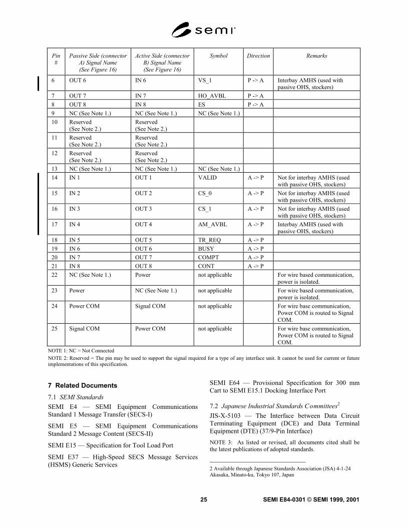
Table 9 Pin Assignments for Connector of Passive Equipment Side
Pin#
Passive Side (connectorA) Signal Name(See Figure 16)
Active Side (connectorB) Signal Name(See Figure 16)
Symbol Direction Remarks
1 OUT 1 IN 1 L_REQ P -> A2 OUT 2 IN 2 U_REQ P -> A3 OUT 3 IN 3 VA P -> A Interbay AMHS (used with
passive OHS, stockers)4 OUT 4 IN 4 READY P -> A5 OUT 5 IN 5 VS_0 P -> A Interbay AMHS (used with
passive OHS, stockers)
SEMI E84-0301 © SEMI 1999, 200125
Pin#
Passive Side (connectorA) Signal Name(See Figure 16)
Active Side (connectorB) Signal Name(See Figure 16)
Symbol Direction Remarks
6 OUT 6 IN 6 VS_1 P -> A Interbay AMHS (used withpassive OHS, stockers)
7 OUT 7 IN 7 HO_AVBL P -> A8 OUT 8 IN 8 ES P -> A9 NC (See Note 1.) NC (See Note 1.) NC (See Note 1.)10 Reserved
(See Note 2.)Reserved(See Note 2.)
11 Reserved(See Note 2.)
Reserved(See Note 2.)
12 Reserved(See Note 2.)
Reserved(See Note 2.)
13 NC (See Note 1.) NC (See Note 1.) NC (See Note 1.)14 IN 1 OUT 1 VALID A -> P Not for interbay AMHS (used
with passive OHS, stockers)15 IN 2 OUT 2 CS_0 A -> P Not for interbay AMHS (used
with passive OHS, stockers)16 IN 3 OUT 3 CS_1 A -> P Not for interbay AMHS (used
with passive OHS, stockers)17 IN 4 OUT 4 AM_AVBL A -> P Interbay AMHS (used with
passive OHS, stockers)18 IN 5 OUT 5 TR_REQ A -> P19 IN 6 OUT 6 BUSY A -> P20 IN 7 OUT 7 COMPT A -> P21 IN 8 OUT 8 CONT A -> P22 NC (See Note 1.) Power not applicable For wire based communication,
power is isolated.23 Power NC (See Note 1.) not applicable For wire based communication,
power is isolated.24 Power COM Signal COM not applicable For wire base communication,
Power COM is routed to SignalCOM.
25 Signal COM Power COM not applicable For wire base communication,Power COM is routed to SignalCOM.
NOTE 1: NC = Not ConnectedNOTE 2: Reserved = The pin may be used to support the signal required for a type of any interface unit. It cannot be used for current or futureimplementations of this specification.
7 Related Documents7.1 SEMI StandardsSEMI E4 — SEMI Equipment CommunicationsStandard 1 Message Transfer (SECS-I)
SEMI E5 — SEMI Equipment CommunicationsStandard 2 Message Content (SECS-II)
SEMI E15 — Specification for Tool Load Port
SEMI E37 — High-Speed SECS Message Services(HSMS) Generic Services
SEMI E64 — Provisional Specification for 300 mmCart to SEMI E15.1 Docking Interface Port
7.2 Japanese Industrial Standards Committees2
JIS-X-5103 — The Interface between Data CircuitTerminating Equipment (DCE) and Data TerminalEquipment (DTE) (37/9-Pin Interface)
NOTE 3: As listed or revised, all documents cited shall bethe latest publications of adopted standards.
2 Available through Japanese Standards Association (JSA) 4-1-24Akasaka, Minato-ku, Tokyo 107, Japan
SEMI E84-0301 © SEMI 1999, 2001 26
APPENDIX 1APPLICATION NOTESNOTE: This appendix was balloted as an official part ofSEMI E84, but the recommendation in this applicationnote is optional and is not required to conform to thisstandard. Rather, these notes are provided primarily asa source of information to aid in the application of thestandard. As such, they are to be considered referencematerial only.
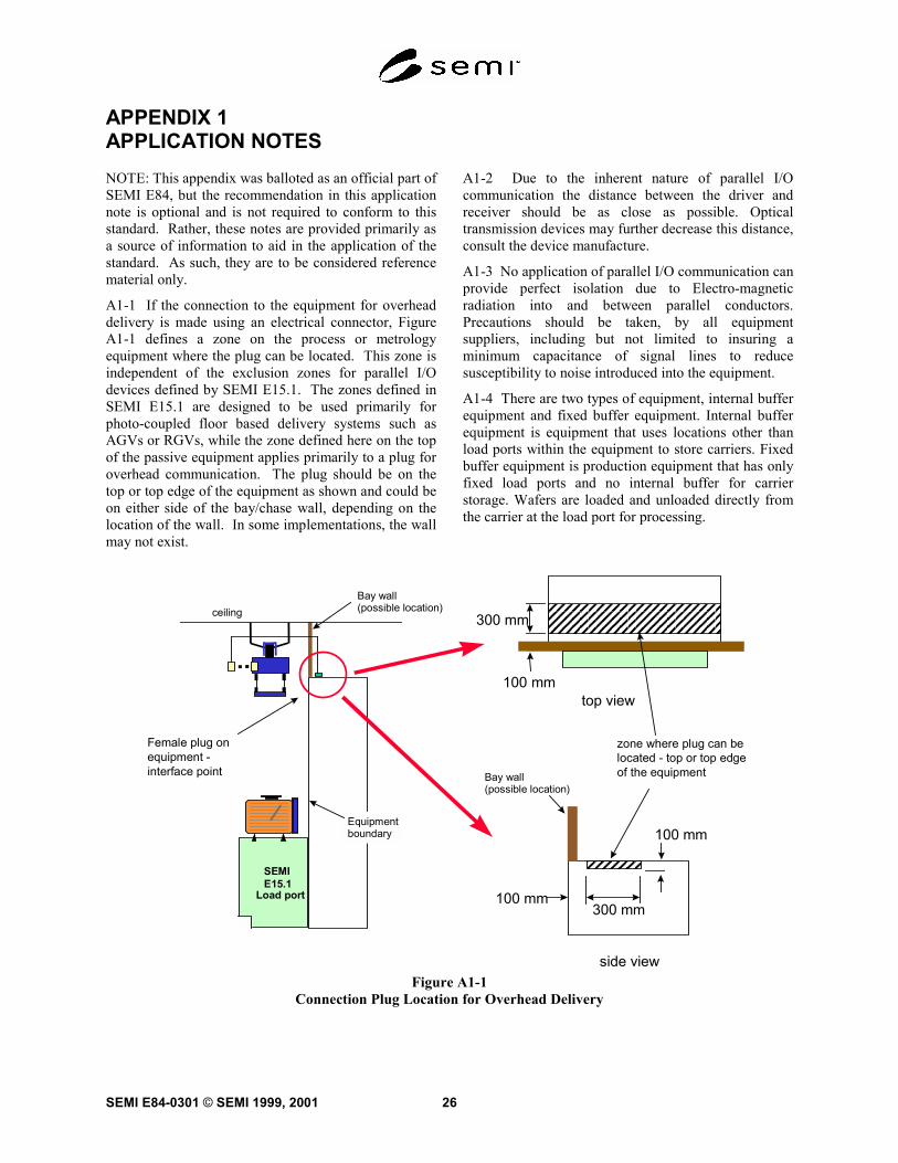
A1-1 If the connection to the equipment for overheaddelivery is made using an electrical connector, FigureA1-1 defines a zone on the process or metrologyequipment where the plug can be located. This zone isindependent of the exclusion zones for parallel I/Odevices defined by SEMI E15.1. The zones defined inSEMI E15.1 are designed to be used primarily forphoto-coupled floor based delivery systems such asAGVs or RGVs, while the zone defined here on the topof the passive equipment applies primarily to a plug foroverhead communication. The plug should be on thetop or top edge of the equipment as shown and could beon either side of the bay/chase wall, depending on thelocation of the wall. In some implementations, the wallmay not exist.
A1-2 Due to the inherent nature of parallel I/Ocommunication the distance between the driver andreceiver should be as close as possible. Opticaltransmission devices may further decrease this distance,consult the device manufacture.
A1-3 No application of parallel I/O communication canprovide perfect isolation due to Electro-magneticradiation into and between parallel conductors.Precautions should be taken, by all equipmentsuppliers, including but not limited to insuring aminimum capacitance of signal lines to reducesusceptibility to noise introduced into the equipment.
A1-4 There are two types of equipment, internal bufferequipment and fixed buffer equipment. Internal bufferequipment is equipment that uses locations other thanload ports within the equipment to store carriers. Fixedbuffer equipment is production equipment that has onlyfixed load ports and no internal buffer for carrierstorage. Wafers are loaded and unloaded directly fromthe carrier at the load port for processing.
Bay wall(possible location)
SEMIE15.1
Load port
ceiling
Female plug onequipment -interface point
Equipmentboundary
top view100 mm
300 mm
zone where plug can belocated - top or top edgeof the equipment
side view
100 mm300 mm
100 mm
Bay wall(possible location)
Figure A1-1Connection Plug Location for Overhead Delivery
SEMI E84-0301 © SEMI 1999, 200127
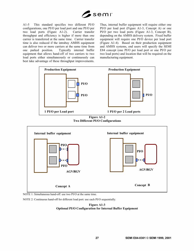
A1-5 This standard specifies two different PI/Oconfigurations, one PI/O per load port and one PI/O pertwo load ports (Figure A1-2). Carrier transferthroughput and efficiency is higher if more than onecarrier is transferred at the same time. Carrier transfertime is also reduced if the intrabay AMHS equipmentcan deliver two or more carriers at the same time fromone parked position. Typically internal bufferequipment that allows hand-off of two carriers to twoload ports either simultaneously or continuously canbest take advantage of these throughput improvements.
Thus, internal buffer equipment will require either onePI/O per load port (Figure A1-3, Concept A) or onePI/O per two load ports (Figure A1-3, Concept B),depending on the AMHS delivery system. Fixed bufferequipment will require one PI/O device per load port(Figure A1-4). Based on their production equipmentand AMHS systems, end users will specify the SEMIE84 concept (one PI/O per load port or one PI/O pertwo load ports) and location that will be required on themanufacturing equipment.
Production Equipment Production Equipment
1 PI/O per 2 Load ports1 PI/O per Load port
PI/O
PI/OPI/O
Figure A1-2Two Different PI/O Configurations
/O
GV
A
PI
Concept
AGV/R/
/
R
PI O
PI O
Concept B
AGV/ GV
Internal equipmentbuffer Internal equipmentbuffer
NOTE 1: Simultaneous hand-off: use two PI/O at the same time.
NOTE 2: Continuous hand-off for different load port: use each PI/O sequentially.
Figure A1-3Optional PI/O Configuration for Internal Buffer Equipment
SEMI E84-0301 © SEMI 1999, 2001 28
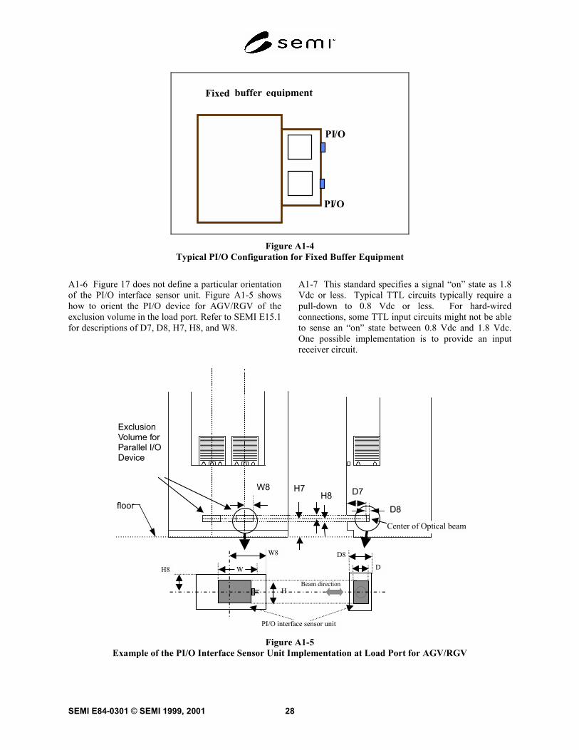
PI/O
PI
Fixed equipment buffer
/O
Figure A1-4Typical PI/O Configuration for Fixed Buffer Equipment
A1-6 Figure 17 does not define a particular orientationof the PI/O interface sensor unit. Figure A1-5 showshow to orient the PI/O device for AGV/RGV of theexclusion volume in the load port. Refer to SEMI E15.1for descriptions of D7, D8, H7, H8, and W8.
A1-7 This standard specifies a signal “on” state as 1.8Vdc or less. Typical TTL circuits typically require apull-down to 0.8 Vdc or less. For hard-wiredconnections, some TTL input circuits might not be ableto sense an “on” state between 0.8 Vdc and 1.8 Vdc.One possible implementation is to provide an inputreceiver circuit.
floorD7
D8
H7W8H8
ExclusionVolume forParallel I/ODevice
Center of Optical beam
PI/O interface sensor unit
Beam directionH
W
W8
H8
D8
D
Figure A1-5Example of the PI/O Interface Sensor Unit Implementation at Load Port for AGV/RGV
SEMI E84-0301 © SEMI 1999, 200129
NOTICE: SEMI makes no warranties or represen-tations as to the suitability of the standards set forthherein for any particular application. The determinationof the suitability of the standard is solely theresponsibility of the user. Users are cautioned to refer tomanufacturer’s instructions, product labels, productdata sheets, and other relevant literature respecting anymaterials mentioned herein. These standards are subjectto change without notice.
The user’s attention is called to the possibility thatsome implementations of this standard may involve useof inventions covered by U.S. patents 4,306,292 andother patents issued or pending, held by TexasInstruments Incorporated. By publication of thisstandard, SEMI takes no position respecting either theapplicability or the validity of these or other patentrights asserted in connection with any item mentionedin this standard. Users of this standard are expresslyadvised that determination of any such patent rights,and the risk of infringement of such rights, are entirelytheir own responsibility.
SEMI E84-0301 © SEMI 1999, 2001 30
RELATED INFORMATION 1APPLICATION NOTESNOTE: This related information section was balloted as an official part of SEMI E84, but the recommendations in this section areoptional and are not required to conform to this standard. Rather, these notes are provided primarily as a source of information toaid the in application of the standard. As such, they are to be considered reference material only.
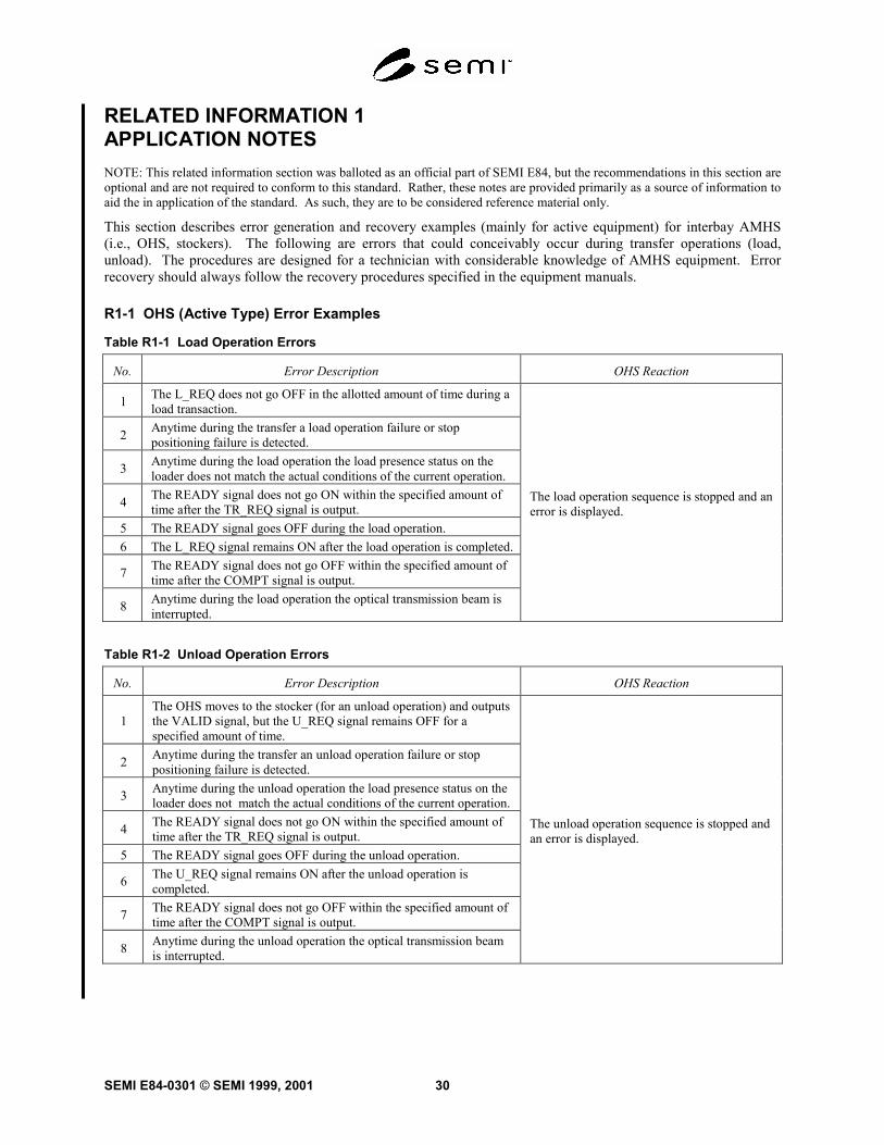
This section describes error generation and recovery examples (mainly for active equipment) for interbay AMHS(i.e., OHS, stockers). The following are errors that could conceivably occur during transfer operations (load,unload). The procedures are designed for a technician with considerable knowledge of AMHS equipment. Errorrecovery should always follow the recovery procedures specified in the equipment manuals.
R1-1 OHS (Active Type) Error Examples
Table R1-1 Load Operation Errors
No. Error Description OHS Reaction
1 The L_REQ does not go OFF in the allotted amount of time during aload transaction.
2 Anytime during the transfer a load operation failure or stoppositioning failure is detected.
3 Anytime during the load operation the load presence status on theloader does not match the actual conditions of the current operation.
4 The READY signal does not go ON within the specified amount oftime after the TR_REQ signal is output.
5 The READY signal goes OFF during the load operation.6 The L_REQ signal remains ON after the load operation is completed.
7 The READY signal does not go OFF within the specified amount oftime after the COMPT signal is output.
8 Anytime during the load operation the optical transmission beam isinterrupted.
The load operation sequence is stopped and anerror is displayed.
Table R1-2 Unload Operation Errors
No. Error Description OHS Reaction
1The OHS moves to the stocker (for an unload operation) and outputsthe VALID signal, but the U_REQ signal remains OFF for aspecified amount of time.
2 Anytime during the transfer an unload operation failure or stoppositioning failure is detected.
3 Anytime during the unload operation the load presence status on theloader does not match the actual conditions of the current operation.
4 The READY signal does not go ON within the specified amount oftime after the TR_REQ signal is output.
5 The READY signal goes OFF during the unload operation.
6 The U_REQ signal remains ON after the unload operation iscompleted.
7 The READY signal does not go OFF within the specified amount oftime after the COMPT signal is output.
8 Anytime during the unload operation the optical transmission beamis interrupted.
The unload operation sequence is stopped andan error is displayed.
SEMI E84-0301 © SEMI 1999, 200131
R1-1.1 Example of the Signal Status When an Error isGenerated During Transfer Operations
R1-1.1.1 OHS Side Error Generation
R1-1.1.1.1 OHS Side Signals — When an error isgenerated, the BUSY signal must stay ON. This is toprevent secondary accidents due to the other deviceoperating on its own.
R1-1.1.1.2 Stocker Side Signals — When an error isgenerated, each signal (except for the READY signal)should remain in the status it was in at the time of theerror. The READY signal should go OFF.
R1-1.1.2 Stocker Side Error Generation
R1-1.1.2.1 Stocker Side Signals — When an error isgenerated, each signal should remain in the status it wasin at the time of the error.
• The READY signal should be OFF.
• The ES signal should be OFF.
• HO_AVBL should be OFF.
R1-1.1.2.2 OHS Side Signals — When an error isgenerated, only the BUSY signal should go ON. Allremaining signals should go OFF.
R1-1.2 Recovery Sequences
R1-1.2.1 Should an error occur during transferoperations (refer to Tables 1 and 2), the recovery shouldbegin by returning the carrier to the stocker or OHS.
Then, the error should be recovered. The four recoveryscenarios are:
1. Load operation, carrier is returned to the stocker.
2. Load operation, carrier is returned to the OHS
3. Unload operation, carrier is returned to the stocker
4. Unload operation, carrier is returned to the OHS
R1-1.3 Recovery Method
R1-1.3.1 OHS Side
• In the case of sequence 2 (above), the load/unloadsequence should be started over from thebeginning.
• In the case of sequence 3 (above), thecorresponding transfer operation should becanceled.
• In the case of sequences 1 and 4 (above) thecorresponding transfer operation should beconsidered completed.
R1-1.3.2 Stocker Side
• In the case of sequences 1 and 4 (above) thecorresponding transfer operation should beconsidered completed.
• In the case of sequences 2 and 3 (above), theload/unload sequence should be started over fromthe beginning.
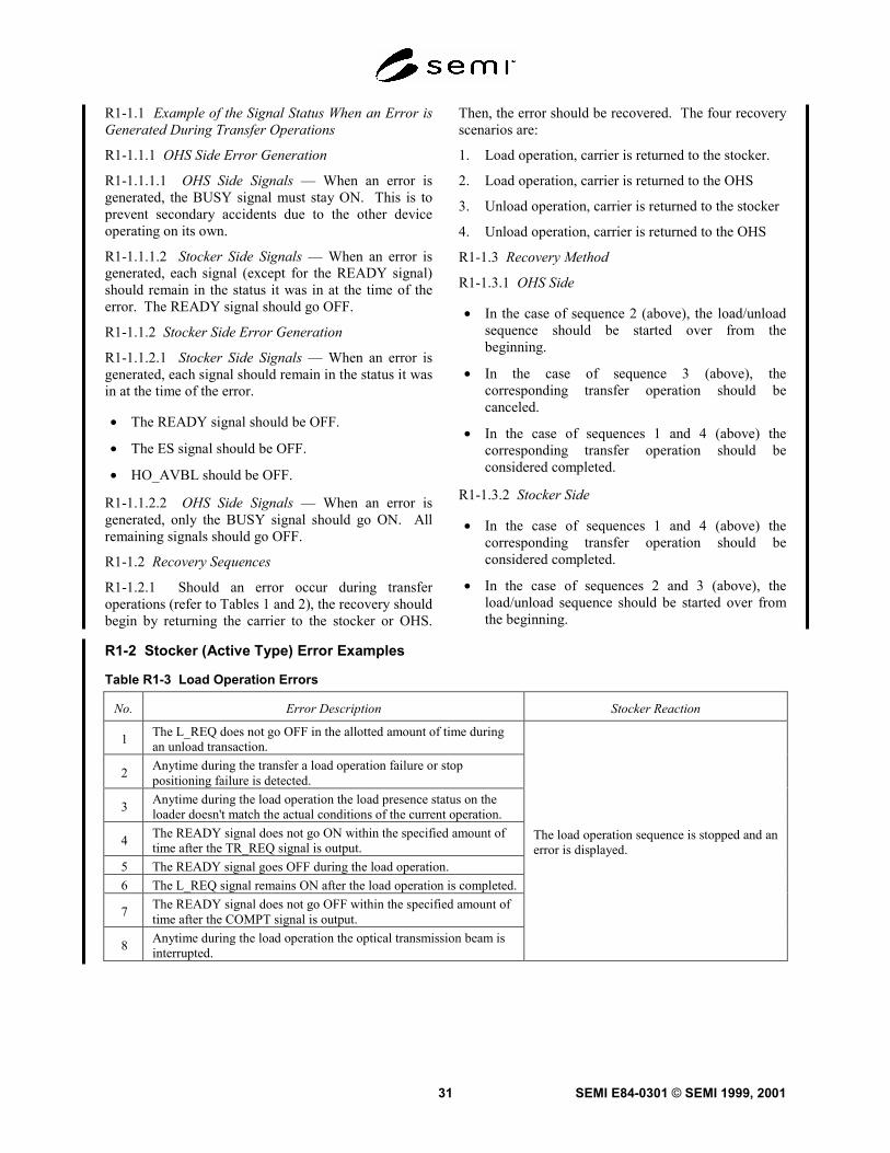
R1-2 Stocker (Active Type) Error Examples
Table R1-3 Load Operation Errors
No. Error Description Stocker Reaction
1 The L_REQ does not go OFF in the allotted amount of time duringan unload transaction.
2 Anytime during the transfer a load operation failure or stoppositioning failure is detected.
3 Anytime during the load operation the load presence status on theloader doesn't match the actual conditions of the current operation.
4 The READY signal does not go ON within the specified amount oftime after the TR_REQ signal is output.
5 The READY signal goes OFF during the load operation.6 The L_REQ signal remains ON after the load operation is completed.
7 The READY signal does not go OFF within the specified amount oftime after the COMPT signal is output.
8 Anytime during the load operation the optical transmission beam isinterrupted.
The load operation sequence is stopped and anerror is displayed.
SEMI E84-0301 © SEMI 1999, 2001 32
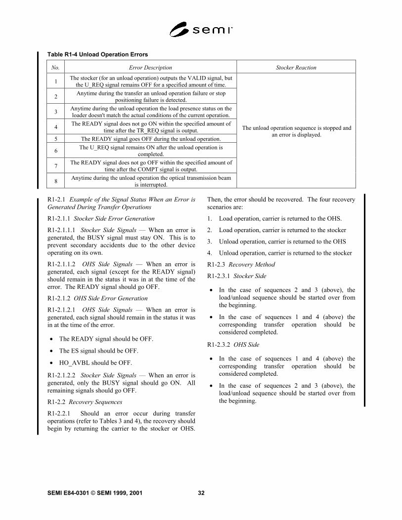
Table R1-4 Unload Operation Errors
No. Error Description Stocker Reaction
1 The stocker (for an unload operation) outputs the VALID signal, butthe U_REQ signal remains OFF for a specified amount of time.
2 Anytime during the transfer an unload operation failure or stoppositioning failure is detected.
3 Anytime during the unload operation the load presence status on theloader doesn't match the actual conditions of the current operation.
4 The READY signal does not go ON within the specified amount oftime after the TR_REQ signal is output.
5 The READY signal goes OFF during the unload operation.
6 The U_REQ signal remains ON after the unload operation iscompleted.
7 The READY signal does not go OFF within the specified amount oftime after the COMPT signal is output.
8 Anytime during the unload operation the optical transmission beamis interrupted.
The unload operation sequence is stopped andan error is displayed.
R1-2.1 Example of the Signal Status When an Error isGenerated During Transfer Operations
R1-2.1.1 Stocker Side Error Generation
R1-2.1.1.1 Stocker Side Signals — When an error isgenerated, the BUSY signal must stay ON. This is toprevent secondary accidents due to the other deviceoperating on its own.
R1-2.1.1.2 OHS Side Signals — When an error isgenerated, each signal (except for the READY signal)should remain in the status it was in at the time of theerror. The READY signal should go OFF.
R1-2.1.2 OHS Side Error Generation
R1-2.1.2.1 OHS Side Signals — When an error isgenerated, each signal should remain in the status it wasin at the time of the error.
• The READY signal should be OFF.
• The ES signal should be OFF.
• HO_AVBL should be OFF.
R1-2.1.2.2 Stocker Side Signals — When an error isgenerated, only the BUSY signal should go ON. Allremaining signals should go OFF.
R1-2.2 Recovery Sequences
R1-2.2.1 Should an error occur during transferoperations (refer to Tables 3 and 4), the recovery shouldbegin by returning the carrier to the stocker or OHS.
Then, the error should be recovered. The four recoveryscenarios are:
1. Load operation, carrier is returned to the OHS.
2. Load operation, carrier is returned to the stocker
3. Unload operation, carrier is returned to the OHS
4. Unload operation, carrier is returned to the stocker
R1-2.3 Recovery Method
R1-2.3.1 Stocker Side
• In the case of sequences 2 and 3 (above), theload/unload sequence should be started over fromthe beginning.
• In the case of sequences 1 and 4 (above) thecorresponding transfer operation should beconsidered completed.
R1-2.3.2 OHS Side
• In the case of sequences 1 and 4 (above) thecorresponding transfer operation should beconsidered completed.
• In the case of sequences 2 and 3 (above), theload/unload sequence should be started over fromthe beginning.
SEMI E84-0301 © SEMI 1999, 200133
RELATED INFORMATION 2APPLICATION NOTESNOTE: This related information section was balloted as an official part of SEMI E84, but the recommendations in this section areoptional and are not required to conform to this standard. Rather, these notes are provided primarily as a source of information toaid the in application of the standard. As such, they are to be considered reference material only.
If the stocker is the active side of the interbay AMHS(i.e., OHS and stockers) it is conceivable that the loaderwill interfere with the OHS passing by the stocker infailure scenarios. As a result of this possibility, it isnecessary for interbay AMHS equipment makers toestablish an OHS "PASS OK" signal separate from theSEMI E84 interlock. However, this note has no directbearing on the contents of SEMI E84. Therefore,readers of SEMI E84 should only treat this as areference item.
Pass Interlock
Interlock Signal
Signal Name P/A Description
PASS OK A->PWhen this signal is HIGH (ON), thevehicle may pass. When this signal isLOW (OFF), the vehicle may not pass.
SEMI E84-0301 © SEMI 1999, 2001 34
RELATED INFORMATION 3NOTE: This related information is not an official part of SEMI E84 and was derived from the work of the E84 Task Force. Thisrelated information was approved for publication by committee vote on October 19, 2000.
R3-1 The E84 Task Force inadvertently omitted theaccompanying information and definitions from the setof E84 line items changes balloted 10/00. To helpclarify the standard, on October 19, 2000 the SEMIPhysical Interfaces and Carriers Committee approvedthe addition of this related information. The SEMI E84Task Force plans to ballot these definitions forinclusion in the E84 standard during the next ballotcycle.
R3-1.1 Add the following underlined text to thefollowing terms:
access mode — a mode in which passive equipmentknows which AMHS equipment (i.e. RGV, AGV, andOHT/OHV) or operator is permitted to make a materialhandoff. In the case of interbay AMHS, this is a modein which the passive equipment knows which AMHSequipment (i.e. OHS and stockers equipped withtransfer devices) is permitted to make a materialhandoff.
automated material handling system (AMHS)equipment — a piece of equipment which has a carriertransfer robot that transfers carriers from and to passiveequipment. It includes rail guided vehicles (RGV),automated guided vehicles (AGV), overhead hoisttransports (OHT), overhead shuttles (OHS) andstockers.
R3-1.2 Add the following terms:
active vehicle – An active OHS vehicle that contains adevice that loads or unloads the carrier from once pieceof equipment to another.
passive vehicle – An active OHS vehicle that does notcontain a device that loads or unloads the carrier fromonce piece of equipment to another.
NOTICE: SEMI makes no warranties orrepresentations as to the suitability of the standard setforth herein for any particular application. Thedetermination of the suitability of the standard is solelythe responsibility of the user. Users are cautioned torefer to manufacturer’s instructions, product labels,product data sheets, and other relevant literaturerespecting any materials mentioned herein. Thesestandards are subject to change without notice.
The user’s attention is called to the possibility thatcompliance with this standard may require use ofcopyrighted material or of an invention covered bypatent rights. By publication of this standard, SEMItakes no position respecting the validity of any patentrights or copyrights asserted in connection with anyitem mentioned in this standard. Users of this standardare expressly advised that determination of any suchpatent rights or copyrights, and the risk of infringementof such rights, are entirely their own responsibility.
Copyright by SEMI® (Semiconductor Equipment and MaterialsInternational), 3081 Zanker Road, San Jose, CA 95134. Reproduction ofthe contents in whole or in part is forbidden without express writtenconsent of SEMI.