Embed Size (px)
Citation preview
semester+
www.semesterplus.comsemester+
www.semesterplus.com
CY 6251 – Engineering Chemistry II – Course material – Unit -V
UNIT V
FUELS AND COMBUSTION
1. FUELS
Fuel is a combustible substance which on burning produces large amount ofheat. This heat can be used economically for domestic and industrial purposes.
Fuel + air(O2) Products + heat
The total quantity of heat given out by a unit mass of fuel on combustion depends mainly on two elements, namely carbon and hydrogen.
C + O2 CO2 + 94 kcals
2H2 +O2 H2O + 68.5 kcals
1.1 Classification of Fuels
The classification of fuels may be divided into two types based on their occurrence and physical state
(i) Primary fuels which occur in nature
(ii) Secondary fuel which is derived from the primary fuel
Fuels may also be classified into three groups:
1. Solid Fuels 2. Liquid Fuels and 3. Gases Fuels.
Sources Solid Liquid Gaseous
Primary
(Natural)
Wood, Coal, Anthracite Crude oil or petroleum Natural gas
Secondary
(Synthetic)
Coke, Charcoal,
Nitro cellulose
Gasoline,Diesel oil, Kerosene and Coal tar
Coal gas, Water gas and Producer gas
1.2 Characteristics of a Good Fuel
i) High calorific value
ii) Moderate ignition temperature.
iii) Moderate velocity of combustion.

semester+
www.semesterplus.comsemester+
www.semesterplus.com
CY 6251 – Engineering Chemistry II – Course material – Unit -V
iv) Low moisture content.
v) Low contents of non-combustible material.vi) Products of combustion should not be harmful.
1.3 Coal
Coal is the most important solid fuel that is derived from vegetable matter. It is chiefly composed of carbon, hydrogen, nitrogen, oxygen and sulphur, besides non-combustible inorganic matter.
1.3.1 Analysis of Coal
Coal composition depends on its source and age. The coal is composed of mixture of organic compounds along with some inorganic matter. The calorific value of coal depends upon its composition.
To confirm the quality or rank of the coal, two types of analysis are carried out:
i) Proximate analysis
ii) Ultimate analysis
i) Proximate analysis
This method is used for determination of percentage of moisture content, volatile matter,ash and fixed carbon in the coal. The proximate analysis gives information about the practical utility of coal.
a) Determination of Moisture: A known amount of the finely powdered coal sample istaken in a silica crucible. Then crucible is placed in an electric hot air-oven, maintained at temperature of 105-110o C. The crucible is allowed to remain in oven for 1 hour.
After one hour, crucible is taken out with the help of tongs, cooled in a desiccator and weighed. The process of heating, cooling and weighing is repeated a number of times till the weight of the crucible containing coal becomes constant. Loss of weight of coal is due to moisture content.
Percentage of Moisture = Loss in weight
Weight of Coal taken x 100
b) Determination of volatile matter:
The dried sample of coal left in the crucible in first experiment is then covered with a lid

semester+
www.semesterplus.comsemester+
www.semesterplus.com
CY 6251 – Engineering Chemistry II – Course material – Unit -V
and placed in an electric furnace, maintained at a temperature of 950o C. The crucible is taken outof the oven after 7 minutes of heating. The crucible is cooled first in air, then cooled in a desiccator and weighed. The process of heating, cooling and weighing is repeated a number of times till the weight of the crucible containing coal (now volatile matter removed) becomes constant. Loss of weight of coal is due to volatile matter.
Percentage of Volatile matter = Weight of volatile matter removed
Weight of moisture free Coal x 100

semester+
www.semesterplus.comsemester+
www.semesterplus.com
CY 6251 – Engineering Chemistry II – Course material – Unit -V
c) Determination of ash:
The residual coal in the crucible in the above experiment is then heated without lid in amuffle furnace at 700o - 750oC for 30 minutes. After 30 minutes crucible is cooled in a desiccatorand weighed.
The process of heating, cooling, and weighing is repeated a number of times till the weight of the crucible become constant. Residue obtained is known as ash.
Weight of ash formed Percentage of Ash =
Weight of dry Coal sample x 100
d) Determination of fixed carbon:
It is determined indirectly by deducting the moisture content, ash and volatile matter from100.
Percentage of fixed carbon = 100 – (% of moisture + % of volatile matter + % of ash)
Significance of proximate analysis or Importance of proximate analysis
Proximate analysis provides following valuable information in assessing the quality of coal.
Coal composition Merits Demerits
Moisture content Presence of small quantity of moisture in coal makes the coal bed uniform and also it reduces the amount of fly ash.
Calorific value gets reduced.
Moisture increases the transport charges.
semester+
www.semesterplus.comsemester+
www.semesterplus.com
CY 6251 – Engineering Chemistry II – Course material – Unit -V
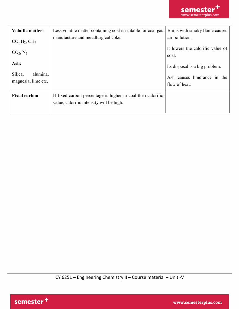
Volatile matter:
CO, H2, CH4
CO2, N2
Ash:
Silica, alumina, magnesia, lime etc.
Less volatile matter containing coal is suitable for coal gas manufacture and metallurgical coke.
Burns with smoky flame causes air pollution.
It lowers the calorific value of coal.
Its disposal is a big problem.
Ash causes hindrance in the flow of heat.
Fixed carbon If fixed carbon percentage is higher in coal then calorific value, calorific intensity will be high.

semester+
www.semesterplus.comsemester+
www.semesterplus.com
CY 6251 – Engineering Chemistry II – Course material – Unit -V
1.4 Coke Manufacture- Carbonisation of Coal
When coal is heated strongly in the absence of air, it loses volatile matter and converted into white, lustrous, dense, strong porous and coherent mass known as coke. This process of converting coal into coke is called carbonisation.
1.4.1 Types of Carbonisation
Depending in the temperature of carbonisation the following three types of carbonisation are usually performed.
i) Low temperature carbonisation (500 to 700oC)
ii) Medium temperature carbonization (700 to 900oC)
iii) High temperature carbonization (above 900oC)
Characteristics Low temperature carbonisation High temperature carbonisation
1.Heating temperature 500-700oC 1000-1200oC
2. Yield 75% 70%
3.VM content 5-15% 1-3%
4. Calorific value 6500-9500 cal g-1 5500-6000 cal g-1
5.Mechanical strength Not mechanically strong Good
6.Use For domestic purposes For metallurgical purposes
1.4.3 Coking and Non coking(caking) Coals
All types of coal cannot be converted into coke. Coals on heating first loose moisture and volatile matter and at high temperatures the mass becomes soft plastic and fuses to give coherent mass. Such coals are called caking coals.
Coals which form a weakly coherent mass on heating are called non-coking (caking) coals. The coke obtained is hard, porous, strong and dense. Thus all coking coals are caking coals but all caking coals are not coking coals. Only bituminous coal can be coked and it is called coking coals. Anthracite, sub-bituminous and lignite are non-coking coals.

semester+
www.semesterplus.comsemester+
www.semesterplus.com
CY 6251 – Engineering Chemistry II – Course material – Unit -V
Metallurgical coke can be manufactured by Otto-Hoffmann‟ s by-product oven method.
1.4.3 Otto-Hoffmann By-Product Oven Method
In this method, (i) thermal efficiency of carbonisation process is considerably increased by the
regenerative system of heat economy
(ii) the valuable by-products like coal gas, ammonia, benzol oil, tar etc., are recovered.
This oven consists (Fig.4.1) of a number of silica chambers, each about 10-12 m long, 3- 4 m tall and 0.4 to 0.45 m wide, erected side by side with vertical flues between them. Each chamber has a hole at the top to introduce the coal, a gas off-take and door at each for discharging the coke.
The chambers are packed with finely divided coal and tightly closed. The coke oven is heated to 1200o C by burning gaseous fuel like producer gas. The fuel gases produced duringburning passes through two sets of cheker-bricks until heated up to 1000o C. The flow of heatedflue gases can be reversed to above system of recycling of flue gases to produce heat energy is known as regenerative system of heat economy. Carbonisation takes about 11 to 18 hours.
Ammonia Spray
Water Spray
Naphf
Cold Water Spray
Petrolium Spray Silica chambers
TAR NH3 thalehe Benzene
semester+
www.semesterplus.comsemester+
www.semesterplus.com
CY 6251 – Engineering Chemistry II – Course material – Unit -V
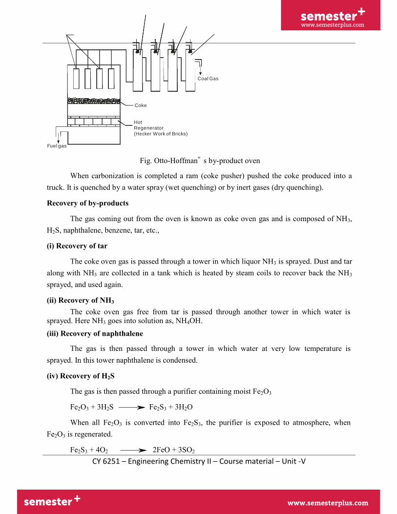
Coal Gas
Coke
Hot
Regenerator
(Hecker Work of Bricks)
Fuel gas
Fig. Otto-Hoffman‟ s by-product oven
When carbonization is completed a ram (coke pusher) pushed the coke produced into a truck. It is quenched by a water spray (wet quenching) or by inert gases (dry quenching).
Recovery of by-products
The gas coming out from the oven is known as coke oven gas and is composed of NH3, H2S, naphthalene, benzene, tar, etc.,
(i) Recovery of tar
The coke oven gas is passed through a tower in which liquor NH3 is sprayed. Dust and tar along with NH3 are collected in a tank which is heated by steam coils to recover back the NH3
sprayed, and used again.
(ii) Recovery of NH3
The coke oven gas free from tar is passed through another tower in which water is sprayed. Here NH3 goes into solution as, NH4OH. (iii) Recovery of naphthalene
The gas is then passed through a tower in which water at very low temperature is sprayed. In this tower naphthalene is condensed.
(iv) Recovery of H2S
The gas is then passed through a purifier containing moist Fe2O3
Fe2O3 + 3H2S Fe2S3 + 3H2O
When all Fe2O3 is converted into Fe2S3, the purifier is exposed to atmosphere, when Fe2O3 is regenerated.
Fe2S3 + 4O2 2FeO + 3SO2

semester+
www.semesterplus.comsemester+
www.semesterplus.com
CY 6251 – Engineering Chemistry II – Course material – Unit -V
4FeO + O2 2Fe2O3
1.4.4 Characteristics of Metallurgical Coke
The characteristics of metallurgical coke are
i) Purity: Metallurgical coke must contain minimum percentage of moisture, ash, sulphurand phosphrous.
ii) Porosity: Metallurgical coke must be porous so that oxygen can easily come in contactwith carbon of the coke, which ensures the efficient combustion.
iii) Strength: Metallurgical coke has to withstand pressure of ore, flux, etc in the furnace soit must have a good mechanical strength.
iv) Size: Metallurgical coke must be uniform and medium sized.
v) Calorific value: The calorific value should be high
vi) Cost: It must be cheap and readily available.
vii) Combustibility: Metallurgical coke should burn easily.
Reactivity: The reactivity of coke refers to its ability to react with O2, CO2, steam and air. Metallurgical coke must have low reactivity.
1.5 Synthetic Petrol
Petrol can be artificially produced by the following methods.
i) Polymerisation
ii) Fischer-Tropsch process
iii) Bergius process
semester+
www.semesterplus.comsemester+
www.semesterplus.com
CY 6251 – Engineering Chemistry II – Course material – Unit -V
1.5.1 Bergius Process
(Hydrogenation of Coal)
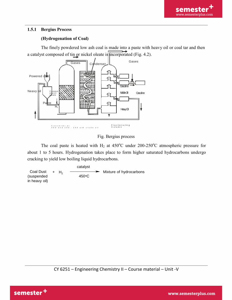
The finely powdered low ash coal is made into a paste with heavy oil or coal tar and then a catalyst composed of tin or nickel oleate is incorporated (Fig. 4.2).
Gases Condenser Gases
Powered coal
Neavy oil
C a t a ly s t s n o r n i o le a t e
H2
Gasoline
MiddleOil Gasoline
Paste
H2
HeavyOil
C o n v e r t e r a t
4 5 0 0 a n d 2 0 0 - 2 5 0 a t m c r u d e o i l
F r a c t i o n a t i n g C o l u m n
Fig. Bergius process
The coal paste is heated with H2 at 450oC under 200-250oC atmospheric pressure forabout 1 to 5 hours. Hydrogenation takes place to form higher saturated hydrocarbons undergo cracking to yield low boiling liquid hydrocarbons.
catalyst
Coal Dust
(suspended
in heavy oil)
+ H2
450oC Mixture of hydrocarbons

semester+
www.semesterplus.comsemester+
www.semesterplus.com
CY 6251 – Engineering Chemistry II – Course material – Unit -V
The vapours leaving the converter upon condensation give crude oil or synthetic petroleum. This synthetic petroleum of fractional distillation gives
(i) petrol (ii) middle oil and (iii) heavy oil
The middle oil on hydrogenation in the vapour phase in presence of a solid catalyst gives gasoline.
Heavy oil is again used for making a paste with coal dust. The yield of gasoline is 60% of the coal dust used.
Fischer – Tropsch Process
i) In this process coal is first converted to coke and the volatile liquids and tars areremoved. Then the coke is heated and steam is passed over it when water gas is produced.
C + H2O CO + H2
Coke Steam water gas Catalyst (Co+Th+Mgo+ Keiselguhr)
Cooler
Fe2O3
Fe2O
3
Na2CO3
Gasoline
Water gas
(CO-H2 )
Purification of gas
Compressor (5-25 atm) Fractionating
Column
Heavy Oil

semester+
www.semesterplus.comsemester+
www.semesterplus.com
CY 6251 – Engineering Chemistry II – Course material – Unit -V
Fig. 4.3 Fischer -Tropsch Method
ii) Synthesis gas is then prepared by mixing water gas and hydrogen in a ratio 2:1. Theprepared synthesis gas is passed through ferric oxide for removal of H2S and through a mixture of ferric oxide and sodium carbonate for removal of organic sulphur compounds.
iii) The purified synthesis gas is compressed to 5 to 25 atmospheres over a cobalt-thoriumoxide catalyst on Kieselgur at 180 – 200oC. Straight chain paraffins and olefins are obtained asreaction products.
n CO + 2n H2 CnH2n + n H2O
Synthesis gas Olefins
n CO + (2n+1) H2 CnH2n+2 + n H2O
n-paraffins
iv) The reaction is exotermic, so out coming hot gaseous mixture is passed through water- cooled condensers, where a liquid resembling crude oil is obtained.
The crude oil thus obtained is sent through fractionating column yield
i) gasoline
ii) High – boiling heavy oil.
The heavy oil is uses fro cracking to get more gasoline.
1.6 Knocking
Knocking is a kind of explosion (sharp metallic sound) produce in the internal combustion engine due to the immature ignition of the air gasoline mixture.
In an internal combustion engine, the gasoline air mixture is highly compressed before it is ignited in order to have maximum efficiency.
Ignition of gasoline air mixture by a spark causes a compression wave to pass through the unburnt gas mixture. Under certain conditions this wave can compress the mixture to above its self-ignition temperature resulting in explosive burning and metallic sound is produced. This is called knocking.
Chemical structure and knocking
The knocking tendency of a gasoline depends upon the nature and molecular structure of

semester+
www.semesterplus.comsemester+
www.semesterplus.com
CY 6251 – Engineering Chemistry II – Course material – Unit -V
the hydrocarbons present in the gasoline. The knocking property is in the following order:
Straight chain alkanes > Branched chain alkanes > Alkenes > Naphthenes > Aromatics
1.6.1 Octane Number
The knocking quality of an automobile fuel is measured in terms of octane number.
n-heptane knocks very badly and its anti-knock value has arbitrarily been fixed as zero. Isooctane (2,2,4- trimethylpentane) gives very little knocking and its anti-knock value has been given as 100.
CH3-CH
2-CH
2-CH
2-CH
2-CH
2-CH
3
n-heptane
CH3
CH3
C
CH3
CH2
CH3
CH CH3
Isooctane(2,2,4-trimethyl pentane)
Octane number of a gasoline is the percentage of isooctane in a mixture of isooctane and n-heptane, which matches the fuel under in knocking.
Example: 80-Octane. This fuel has same combustion characteristics as an 80:20 mixture of isooctane and n-heptane.
1.6.1.1 Improvement of anti knocking characteristics of a fuel
Leaded petrol (sweetening of petrol)
The octane number of a fuel can be raised by the addition of a small amount of Tetra Ethyl Lead (TEL) or TEL and diethyl telluride. This process is known as doping. In motor fuel about 0.5 ml of TEL is added per litre of petrol. This petrol is called leaded petrol.
In addition to TEL, a small amount of ethyl fluoride (a mixture of ethylene bromide, ethylene chloride and red dye) is also added.

semester+
www.semesterplus.comsemester+
www.semesterplus.com
CY 6251 – Engineering Chemistry II – Course material – Unit -V
1.6.2 Cetane Number
In diesel engine, the fuel is exploded not by a spark, but by the application of heat and pressure.
The main characteristic of a diesel engine fuel is that it should easily ignite below compression temperature. The induction lag should be as short as possible. Otherwise the entire amount of oil may get accumulate and will burn suddenly. This cause a great rise in pressure and makes minor explosion in diesel engine.
The cetane number decreases in the following order.
Straight chain alkanes > Cycloalkanes > Alkenes > Branched alkanes > Aromatics
The number used for rating diesel oil is called cetane number.
This represents the spontaneous ignition temperature of the fuel.
CH3
2-methyl naphthalene (cetane number = 0)
CH3 CH2 CH3
14
n-hexadecane
(cetane number = 100)
Cetane (n-hexadecane) ignites more rapidly than any fuel and its cetane number has been designed as 100. α-methyl naphthalene ignites slowly than any other fuel and its cetane number is 0.
Cetane number of a fuel is defined as the percentage of cetane present in a mixture of cetane and α-methyl naphthalene, which matches the fuel under test in ignition.
1.6.2.1 Improvement of Cetane Number
The cetane number of a fuel can be increased by the addition of a small amount of (pre- ignition dopes) ethyl nitrate, isoamyl nitrate and acetone.
1.6.2.2 Diesel Index
According to the American Petroleum Institute (API) the quality of diesel can be expressed by Diesel Index.
semester+
www.semesterplus.comsemester+
www.semesterplus.com
CY 6251 – Engineering Chemistry II – Course material – Unit -V
The higher the diesel index the better is the quality of the fuel.
Specific gravity (API) x Aniline point (F) Diesel Index =
100

semester+
www.semesterplus.comsemester+
www.semesterplus.com
CY 6251 – Engineering Chemistry II – Course material – Unit -V
Relation between Diesel index and cetane number
Diesel Index = Cetane number + 3
1.7 Producer Gas
Composition:
Combustible gases Non– combustible gases
Co = 22-30% N2 = 52-55%
H2= 8-12% CO2 = 3%
Producer gas is a mixture of CO and N with small proportion of hydrogen, methane and carbon-di-oxide.
Manufacture:
It is prepared by passing a mixture of air and steam over a bed of red-hot coke (or) coal. Since a low-grade coal can be used in producing producer gas, its cost comes out to below.
Fig.4.4 Manufacture of Producer gas
Actually, it is considered as the cheapest gaseous fuel. But due to the presence of a large proportion of nitrogen, its calorific value is the lowest of all gaseous fuels.
When a mixture of air and steam is passed over red hot coke or coal bed at about 1000o to1100oC producer gas is formed. The following reactions take place in different zones of the fuelbed.
Reactions: The gas production reactions can be divided into two zones as follows.
semester+
www.semesterplus.comsemester+
www.semesterplus.com
CY 6251 – Engineering Chemistry II – Course material – Unit -V
i) Combustion (or) Oxidation zone
The solid fuel is fed at the top of this refractory lined reaction vessel and air mixed with avery little steam is injected from bottom. In lower part of furnace carbon from coal combines
with oxygen of air to form carbon monoxide and carbon-di-oxide. The temperature of this zone is about 1,100oC
C + O2 CO2 (Oxidation)
ii) Reduction zone
This is the middle part of the fuel bed. Here CO2 and steam are reduced. Here, CO2 andsteam move up through red hot fuel bed and the following reactions take place.
C + CO2 2CO (Reduction)
C + H2O CO + H2
C + 2H2O CO2 + 2H2
Nitrogen (of air) remains unaffected throughout the process. Both these reactions are endothermic. Hence the coal bed has only around 1000oC; in this zone (temperature falls).
In order to maintain the temperature of the bottom of the coal bed at about 1100oC (whichis essential for the oxidation reaction) the quantity of the steam admitted along with air cannot be increased beyond a certain limit.
iii) Pre-heating and Distillation zone: This is the upper part of the fuel bed. In thisuppermost zone of the coal bed temperature is between 400oC and 800oC.
In this zone the incoming coal fed from the top is heated by the outgoing gases and heat radiated from the reduction zone helps to distil the fuel, thereby volatile matter in the coal is now transferred to the producer gas in this zone.
Further, all the gases formed namely CO, N2, CO2, H2 etc. pass out through the outlet.
iv) Ash zone
The lowest zone consists mainly of ash, and therefore, it is known as ash zone.
The ash protects the plant from the intense heat of combustion. Moreover, thetemperature of air and steam supplied is increased as they pass through this zone.
Uses:
1. The fuel is economical as it can be obtained by using even low grade coal.

semester+
www.semesterplus.comsemester+
www.semesterplus.com
CY 6251 – Engineering Chemistry II – Course material – Unit -V
2. It is used for heating open-hearth furnace, glass furnace, muffle furnace etc.
3. It can be used as reducing agent in metallurgic operation.
1.8 Water gas (or Blue gas)
Composition:
Combustible gases Non-combustible gases CO = 40-42% CO2 = 3-5%
H2 = 48-51% N2 = 3-6%
Calorific value: 27,800 kcals/m3
The term, „Water gas‟ has been given to the mixture of combustible gases CO and H2 because water in the form of steam is used to make this mixture of gases. Since this gas burns with a blue flame because of its high carbon monoxide content it is also known as blue gas.
Manufacture:
It is prepared by passing steam and little air through a bed hot coal (or) coke. The reaction takes place at about 900o to 1000oC
Reactions:
Water gas is prepared by reacting steam over red hot coke in a cyclic process comprising of the following two main steps:
i) Air is passed through the coke bed when carbon burns to CO2 and the temperature of thefuel bed increases to over 1000oC
C + (O2 + N2) Air CO2 + N2 (exothermic)
The outgoing gases containing CO2 and N2 are used to preheat the incoming air and steam.
ii) Steam is now blown through the red hot coke when CO and H2 are produced. This is letout through the water gas outlet.
At higher temperatures C + H2O CO + H2 (endothermic)
At lower temperatures C + 2H2O CO2 + 2H2 (endothermic)
semester+
www.semesterplus.comsemester+
www.semesterplus.com
CY 6251 – Engineering Chemistry II – Course material – Unit -V
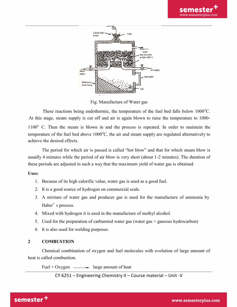
Fig. Manufacture of Water gas
These reactions being endothermic, the temperature of the fuel bed falls below 1000oC.At this stage, steam supply is cut off and air is again blown to raise the temperature to 1000-
1100o C. Then the steam is blown in and the process is repeated. In order to maintain thetemperature of the fuel bed above 1000oC, the air and steam supply are regulated alternatively toachieve the desired effects.
The period for which air is passed is called “hot blow” and that for which steam blow is usually 4 minutes while the period of air blow is very short (about 1-2 minutes). The duration of these periods are adjusted in such a way that the maximum yield of water gas is obtained.
Uses:
1. Because of its high calorific value, water gas is used as a good fuel.
2. It is a good source of hydrogen on commercial scale.
3. A mixture of water gas and producer gas is used for the manufacture of ammonia by
Haber‟ s process.
4. Mixed with hydrogen it is used in the manufacture of methyl alcohol.
5. Used for the preparation of carbureted water gas (water gas + gaseous hydrocarbon)
6. It is also used for welding purposes.
2 COMBUSTION
Chemical combination of oxygen and fuel molecules with evolution of large amount of heat is called combustion.
Fuel + Oxygen large amount of heat

semester+
www.semesterplus.comsemester+
www.semesterplus.com
CY 6251 – Engineering Chemistry II – Course material – Unit -V
2.1 Calorific value
It is the total quantity of heat liberated when an unit mass of the fuel is completely burnt.
2.1.1 Higher (or) Gross Calorific Value (HCV OR GCV)
Hydrogen is present in almost all fuels. When the calorific value is determined, hydrogen is converted into steam. If the products of combustion are condensed to room temperature, the latent heat of condensation of steam is also included in the measured heat. This value is called higher or gross calorific value.
The higher or gross calorific value is the total amount of heat produced when an unit quantity of the fuel is completely burnt and the products of combustion are cooled to room temperature.
2.1.2 Lower (or) Net Calorific Value (LCV OR NCV)
In actual practice the water vapours escape along with hot combustion gases. Hence, a lesser amount of heat is available. This is called lower or net calorific value.
Lower or net calorific value is defined as the net heat produced when an unit quantity of the fuel is completely burnt and the products of combustion are allowed to escape.
Relationship between higher and lower calorific values
NCV = Gross calorific value – latent heat of water vapour formed
= GCV – Mass of hydrogen x 9 x latent heat of steam
= GCV – Mass of hydrogen x 9 x 587 kcals/kg.
2.1.3 Dulong’s formula
(Theoretical Calculation of Calorific Value)
The calorific value from the chemical composition of the fuel is calculated based on Dulong‟ s formula.
GCV or HCV =
1
C 34500 H
O 2240S kcals/kg
100 8080 8
Where C, H, O and S are the % of Carbon, Hydrogen, Oxygen and Sulphur in the fuel.

semester+
www.semesterplus.comsemester+
www.semesterplus.com
CY 6251 – Engineering Chemistry II – Course material – Unit -V
NCV or LCV = HCV 9
xHx587 100
kcals/kg
2.2 Simple Problem
A coal has the following composition in ultimate analysis: C=80% S=2.5% N=0.6% H=7.5% and oxygen 9.4%. Find the gross and net calorific values with the help of Dulong‟ s formula.
Solution:
C=80% S=2.5% H=7.5% O=9.4%.
GCV or HCV =
1
C 34500 H
O 2240S kcals/kg
100 8080 8
= (1/100) [8080 x 80+34500(7.5-9.4/8)+2240 x 2.5]
= (1/100) [646400+34500(7.5-1.175)+5600]
GCV = 8702 kcals/kg
NCV = [GVC – 9/100 x H x 587]
= [8702-9/100 x 7.5 x 587]

semester+
www.semesterplus.comsemester+
www.semesterplus.com
CY 6251 – Engineering Chemistry II – Course material – Unit -V
= 8702 - 396.225
= 8306 kcals/kg
2.3 Calculation of theoretical oxygen and air requirement
Combustion is an exothermic chemical reaction accompanied by the increase of heat.
C + O2 CO2 (g) + 97Kcals
The minimum quantity of air required for the complete combustion of the fuel can be calculated from the percentage composition of the fuel. The main elements present in most of the fuels are C, H, O and S.
Combustion of carbon
C(s) + O2 (g) CO2 (g)
12 32 44
12 kg of Carbon requires oxygen for complete combustion = 32 kg
The given carbon (C kg) in the fuel requires oxygen for complete combustion
= 32
xC 12
Combustion of hydrogen
2H2 (g) + O2 (g) 2H2O (l)
4 32 36
4 kg of hydrogen requires oxygen for complete combustion = 32 kg
The given hydrogen (H kg) in the fuel required oxygen for complete combustion
= 32
xH kg 4
From the total amount of hydrogen in the fuel part of hydrogen are non combustible in the form of water.
8 part of oxygen combines with 1 part of hydrogen
The amount of hydrogen available for combustion
= H O 8

semester+
www.semesterplus.comsemester+
www.semesterplus.com
CY 6251 – Engineering Chemistry II – Course material – Unit -V
Oxygen required for the complete combustion of hydrogen
32 O = H 4 8
Combustion of sulphur S(s) + O2 (g) SO2 (g)
32 kg of sulphur required oxygen for complete combustion = 32 kg
The given sulphur in the fuel requires oxygen for complete combustion = 32 xS kg
32
On combining the above three combustion equations we get the equation for the theoretical oxygen requirement for the combustion of C, H and S.
C 8 H
S 32 =
12 O
8
Minimum weight of air required for complete combustion = 100 23
C 8 H
S 32
12
O
8
Minimum volume of air required
C 8 H
S
= 100
32 O
Example 1
21 12 8
Calculate the weight and volume of air required for the combustion of 1 kg of coal.
Solution:
According to combustion equation
C(s) + O2 (g) CO2 (g)
Weight of oxygen required by 1Kg of coal = 32/12
= 2.667 kg of oxygen

semester+
www.semesterplus.comsemester+
www.semesterplus.com
CY 6251 – Engineering Chemistry II – Course material – Unit -V
Air contains 23% of oxygen by weight
Weight of air required = 2.667 x (100/23)
= 11.59 kg.
Example 2
Calculate the minimum volume of air used for the complete combustion of a fuel having the following composition by weight.
C=92% H2=4% O2= 2% ash =2%
Minimum volume of air required for combustion
C 8 H
S
= 100
32 O 21 12 8

semester+
www.semesterplus.comsemester+
www.semesterplus.com
CY 6251 – Engineering Chemistry II – Course material – Unit -V
=13.11m3
= (100/21) x [(32/12) x 0.92 + 8 (0.04-0.02) + 0]
2.4 Flue gas Analysis (Orsat’s Method)
The hot gases coming out after the combustion of a fuel is called flue gas. The flue gas contains carbonmonoxide, carbondioxide, oxygen, etc.
Significance of Flue gas:
Flue gas analysis gives idea about the complete or incomplete combustion process. The presence of a high CO in the flue gas shows incomplete combustion of the fuel and also indicates the short supply of O2. If the flue gas contains a considerable amount of O2 it indicates an excess supply of oxygen.
Description of Orsat’s apparatus
The Orsat apparatus consists of a horizontal tube with a three way stop-cock at one end and water jacketed measuring burette at the other end. The free end of the three way stop cock is connected to a U-tube packed with fused CaCl2. The graduated burette is surrounded by a water jacket to keep the temperature of the flue gas constant. The lower end of the burette is connected to a water reservoir by means of a rubber tube. The level of water in the water reservoir can be raising or lowering the water reservoir (Fig.4.6)
Flue gas Three-way stop cock
Graduated
burette Separating funnel
Fused calcium chloride
Absorption bulb for carbon dioxide
A B C
Absorption bulb for oxygen Absorption bulb for
carbon monoxide
Water Jacket
Fig. Orsat‟ s apparatus
The central portion of the horizontal tube is connected with three different absorption bulbs A, B and C. Bulb A contains KOH solution and it absorbs CO2 only. Bulb B contains alkaline pyrogallic acid (pyrogallic acid + KOH + water) to absorb CO2 and O2. Bulb C contains

semester+
www.semesterplus.comsemester+
www.semesterplus.com
CY 6251 – Engineering Chemistry II – Course material – Unit -V
ammoniacal cuprous chloride (cuprous chloride + liqour ammonia + water) and it can absorb CO2, O2 and CO.
Working of Orsat’s apparatus

semester+
www.semesterplus.comsemester+
www.semesterplus.com
CY 6251 – Engineering Chemistry II – Course material – Unit -V
Step 1
To start with, the whole apparatus is thoroughly cleaned and properly greased. The

semester+
www.semesterplus.comsemester+
www.semesterplus.com
CY 6251 – Engineering Chemistry II – Course material – Unit -V
absorption bulbs are filled with the respective solutions to level just below their rubber connections. Their stop cocks are then closed.
The three way stop cock is opened to the atmosphere and reservoir is raised till the burette is completely filled with water. This removes air present in the burette. Now the three way stop cock is connected to the flue gas supply and the reservoir is lowered to draw the flue gas in. The sample gas mixes with some air present in the apparatus. So the three way stop cock is opened to the atmosphere to expel the gas. This process is repeated 3-4 times for completely removing the air in the apparatus.
The flue gas is sucked in the burette by opening the three way stop cock and by lowering the water reservoir. The volume of the gas taken in the burette is 100 ml at atmospheric pressure. The three way stop cock is now closed.
Step 2
The stopper of the bulb A is opened and the gas is passed into this bulb by raising the water reservoir. CO2 present in the flue gas is absorbed by KOH. The gas is again sent to the burette. This process is repeated several times to ensure complete absorption of CO2. The unabsorbed gas is finally taken back to the burette by raising the liquid in the bulb A till it is filled completely. Now the stopper of bulb A is closed. The level of water in the burette and reservoir are equalized and the column of residual gas is noted. The decrease in volume gives the volume of CO2 in 100ml of the flue gas.
Step 3
The quantities of O2 and CO are similarly determined by passing the remaining gas through bulb B and C respectively. The gas remaining in burette after absorption of CO2, O2 and CO is taken as N2
Percentage of N2 = 100 - Percentage of (CO2+O2+CO)
Precautions
1. All the air in the apparatus should be completely removed.
2. It is a must to follow the order of absorbing the gases, CO2 first, O2 second and CO last.
2. Ultimate analysis
Ultimate deals with the determination of carbon, hydrogen, nitrogen, oxygen and sulphurin coal. This analysis gives exact results which are useful in calculating calorific value of coal by using Dulong formula.
semester+
www.semesterplus.comsemester+
www.semesterplus.com
CY 6251 – Engineering Chemistry II – Course material – Unit -V
i) Determination of carbon and hydrogenCoal sample is strongly heated with dry cupric oxide in presence of dry oxygen. Carbon
present is oxidized to CO2 while hydrogen present is oxidized to water vapour.
C + O2 CO2
H2 + ½ O2 H2O
After complete combustion the products enter through two bulbs, one containing weighed amount of anhydrous CaCl2 which absorbs water and the other containing weighed amount of KOH which absorbs CO2.
When the reaction is over, the absorption apparatus is disconnected and weighed. The increase in the weight of CaCl2 bulb represents the weight of water formed, while the increase in the weight of KOH bulb represents the weight of CO2 formed.
Knowing the weights of these products % of carbon and % of hydrogen can be calculated.
12 Percentage of Carbon =
44
Weight of CO2 formed
Weight of Coal sample x 100
2 Percentage of Hydrogen =
18
Weight of H2O formed
Weight of Coal sample x 100
ii) Determination of Nitrogen (Kjeldahl’s method)
Kjeldahl‟ s method is used for this purpose. In this method coal is heated withconc. H2SO4 in the presence of K2SO4 and CuSO4. Indirectly the whole nitrogen present in the coal sample is converted into ammonium sulphate and a clear solution is obtained. The % of nitrogen present in the coal sample can be calculated by volumetric analysis.
2N + 6H + H2SO4 (NH4)2SO4
The solution is then treated with 50% NaOH, so as to liberate ammonia.
(NH4)2SO4 + NaOH 2NH3↑ + Na2SO4 + 2H2O
The liberated ammonia is then distilled over and absorbed in known quantity of std. H2SO4
semester+
www.semesterplus.comsemester+
www.semesterplus.com
CY 6251 – Engineering Chemistry II – Course material – Unit -V
2NH4 + H2SO4 (NH4) 2 SO4
Unused quantity of sulphuric acid (V2) is determined by titrating it against standard NaOH solution by back titration. A blank titration is carried out to know the volume of total sulphuric acid (V1) in terms of standard NaOH. The difference between blank titration (V1-V2) gives the amount of sulphric acid used to absorb ammonia.
semester+
www.semesterplus.comsemester+
www.semesterplus.com
CY 6251 – Engineering Chemistry II – Course material – Unit -V
4
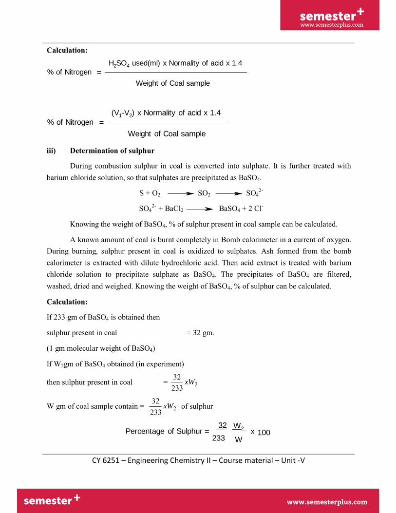
Calculation:
% of Nitrogen =
H2SO4 used(ml) x Normality of acid x 1.4
Weight of Coal sample
% of Nitrogen =
(V1-V2) x Normality of acid x 1.4
Weight of Coal sample
iii) Determination of sulphur
During combustion sulphur in coal is converted into sulphate. It is further treated withbarium chloride solution, so that sulphates are precipitated as BaSO4.
S + O2 SO2 SO 2-
SO42- + BaCl2 BaSO4 + 2 Cl-
Knowing the weight of BaSO4, % of sulphur present in coal sample can be calculated.
A known amount of coal is burnt completely in Bomb calorimeter in a current of oxygen. During burning, sulphur present in coal is oxidized to sulphates. Ash formed from the bomb calorimeter is extracted with dilute hydrochloric acid. Then acid extract is treated with barium chloride solution to precipitate sulphate as BaSO4. The precipitates of BaSO4 are filtered, washed, dried and weighed. Knowing the weight of BaSO4, % of sulphur can be calculated.
Calculation:
If 233 gm of BaSO4 is obtained then
sulphur present in coal = 32 gm.
(1 gm molecular weight of BaSO4)
If W2gm of BaSO4 obtained (in experiment) 32
then sulphur present in coal =
32
xW2233
W gm of coal sample contain = xW2233 of sulphur
32 W2 Percentage of Sulphur = 233
x 100 W

semester+
www.semesterplus.comsemester+
www.semesterplus.com
CY 6251 – Engineering Chemistry II – Course material – Unit -V
Where W = weight of coal taken
W2 = weight of BaSO4 formed.
iv) Determination of oxygenIt is determined indirectly by deducting the combined percentage of C, H, N, S and
ash from 100
Percentage of oxygen = 100 - (% of C + H +N +S +
ash) Note : ash % is determined as done in proximate
analysis.
Significance of Ultimate Analysis
Element present in coal
Merits Demerits
Carbon and hydrogen
Calorific value of coal increases with the increase in % of carbon and hydrogen. Also the quality of coal will be better if percentage of these elements is higher.
Normally hydrogen present in coal sample is in the form of water. So, major portion of heat energy is wasted.
Nitrogen Nitrogen present in coal sample doesn‟ t have any calorific value because nitrogen is an inert and incombustible matter.
Sulphur Sulphur increases the calorific value
of coal. During combustion it emits harmful gases like SO2, SO3 which causes air pollution.
Oxygen Oxygen present in coal is in the form of water. Thus equivalent amount of hydrogen is not available for combustion and thus the calorific value accordingly decreases.
14.20 Natural Gas

semester+
www.semesterplus.comsemester+
www.semesterplus.com
CY 6251 – Engineering Chemistry II – Course material – Unit -V
Natural gas is formed by the decomposition of organic
matter. The natural gas is found along with crude petroleum
and coal. Compressed natural gas is known as CNG.
Natural gas is mainly composed of methane and other saturated hydrocarbons. A typical natural gas has the following compositions.
Methane = 85% Butane = 1.5%
Ethane = 8 % Higher hydrocarbons = 1.5%
Propane = 4% CO2, CO, N2, H2S = trace levels
Trace level quantities like CO2, CO, N2, H2S are removed by suitable treatment before it reaches the consumer.
If lower hydrocarbons are mainly present (methane and ethane) in natural gas then the particular natural gas is called “dry gas”( marsh gas).
If higher hydrocarbons are mainly present along with then the particular natural gas is called “wet gas”.
Natural gas is cheap as well as convenient fuel and it burns with hot blue flame.
Its calorific value is very high (12000 14000 kcal/m3).
It is used for domestic and industrial purposes.
Natural gas is used as a raw material for the synthesis of methanol, carbon black (a filter for rubber) and formaldehyde.
6. PETROLEUM (CRUDE OIL)Petroleum is a dark coloured viscous liquid found deep in earth‟ s crust. Chemically, it is a mixture of various types of hydrocarbons along with some oxygen, sulphur and nitrogen containing compounds.
7.1. REFINING OF PETROLEUM The Crude oil as such is of little important. However, it is separated into various useful fractions by fractional distillation. This is called refining of petroleum.
(i) Separation of water (Cottrell‟ s process)
The crude oil is an extremely stable emulsion of oil and salt water. The crude oil

semester+
www.semesterplus.comsemester+
www.semesterplus.com
CY 6251 – Engineering Chemistry II – Course material – Unit -V
is allowed to flow through two highly charged electrodes. The colloidal water droplets coalesce to form large drops, which separate out from the oil.
(ii) Removal of harmful sulphur compounds
The oil treated with copper oxide. The copper sulphide formed is removed by filtration.
(iii) Fractional distillation
The crude oil is heated to about 400oC in and iron retort, where all volatileconstituents evaporate except the asphalt residue. The hot vapours are passed into a fractionating column (buffle tower) (Fig.14.3). 7.2. Major fraction products from crude oil
Sl.No. Name of fraction Boiling range Average composition in terms of hydrocarbons
Applications
1. Uncondensed gas <30oC Lower hydrocarbons (C1-C4)
Used as domestic industrial fuel(LPG)
2. Petroleum ether 40-80oC C5-C7 As solvent
3. Gasoline 40-120oC C8-C9 As motor and aviation fuel and for dry cleaning work
4. Naptha (solvent spirit) 120-180oC C9-C10 As solvent; as feed stock for petrochemicals
5. Kerosene oil 180-250oC C10-C16 For lighting purposes; feed stock for reforming processes.
6. Diesel oil 250-320oC C16-C16 As engine fuel
7. Heavy oil 320-400oC C17-C30 For getting gasoline by cracking

semester+
www.semesterplus.comsemester+
www.semesterplus.com
CY 6251 – Engineering Chemistry II – Course material – Unit -V
8. Lubricating oil - - As lubricant
9. Vaseline - - In cosmetics and medicine
10. Grease - - As lubricant
11. Paraffin wax - - In candles, boot polish, tarpaulin,etc.,
12. Residue (a)Asphalt
(b)Petroleum
>400oC C30 and above In road topping, water proofing of roofs. As a fuel and in moulding work.
The fractioning column is a tall cylindrical tower containing a number of horizontal steel trays one over another of a fixed distance. Each tray is provided with small chimney covered with loose cap.
As the vapours go up, they become cooled and condensed. Higher boiling fractions condense first, while the lower boiling fractions turn-by-turn. The different fractions obtained at different trays are shown in the table 7.2
8. CRACKINGCracking is defined as the decomposition of higher molecular weight hydrocarbon
molecules (high b.pt) into smaller molecular weight hydrocarbon (low b.pt)
cracking
C10H22 → C5H10 + C5H12
Decane n-pentene n-pentane
o o B.pt=174 C B.pt=36 C
There are two methods of cracking
8.1 THERMAL CRACKING Cracking is carried out by the application of heat and pressure is known as thermal cracking. Here the bigger hydrocarbon molecules break down to give smaller molecules of alkanes, alkenes and some hydrogen.
Thermal cracking may be carried out either in liquid phase or in vapour phase.

semester+
www.semesterplus.comsemester+
www.semesterplus.com
CY 6251 – Engineering Chemistry II – Course material – Unit -V
a. Liquid phase thermal cracking
The heavy oil is cracked at a temperature of 475-530oC and pressure of about 100kg/cm. the cracked products are then separated in a fractioning column.
The yield is 50-60% and octane rating of petrol is 65-70%
b. Vapour phase thermal cracking
This type of cracking is suitable for oils which may be readily vapourised. The crude oil is first vapourised and then cracked at about 600-650oC. Petrol obtained hasbetter antiknocking properties.
8.2 CATALYTIC CRACKING Cracking is carried out using a catalyst is known as catalytic cracking. The catalyst used is aluminium silicate or alumina.
8.3 ADVANTAGES OF CATALYTIC CRACKING 1. The yield of petrol is higher2. The quality of petrol is better3. A much lower pressure is needed4. The cracking process can be controlled5. No external fuel is necessary for cracking6. The product contains very little amount of undesirable products.7. The percentage of gum and gum forming compounds are low.8. Catalysts are selective in their action, and therefore cracking of higher boiling
hydrocarbon takes place.9. The product contains a higher amount of aromatic and hence better antiknocking
property.8.4. CATALYTIC CRACKING METHODS
There are two types of methods for catalytic cracking
a. Fixed bed catalytic crackingb. Moving bed or Fluid bed catalytic cracking
8.4.1. Fixed bed catalytic cracking The heavy oil fraction is heated in a particular in a preheater at a temperature of 420- 450oC. The vapours are then forced into a catalytic chamber containing artificial claymixed with zirconium oxide. The temperature of the chamber is 425-450oC and pressureis 1.5 kg/cm. cracking of the oil takes place. About 40% of the charge is converted into gasoline and about 2-4% carbon is formed. This carbon gets deposited over the catalyst bed. The cracked vapours are then passed into a fractionating column. The gasoline vapours and other gaseous products are obtained from the top, while the heavy oil condenses at the bottom. These vapours are passed into a cooler where gasoline is condensed along with some gaseous products. The gasoline containing some dissolved

semester+
www.semesterplus.comsemester+
www.semesterplus.com
CY 6251 – Engineering Chemistry II – Course material – Unit -V
gases is sent to a stabilizer, where the dissolved gases are removed and pure gasoline is obtained.
Due to the deposition of carbon black over the catalyst bed, the catalyst stops functioning after 8-10 hours. This is reactivated by burning off the deposited carbon.
8.4.2. Moving bed (or) Fluid bed catalytic cracking The solid catalyst is very finely powdered, so that it behaves as a fluid, which can be circulated in gas stream.
The vapours of the gas oil or heavy oil mixed with fluidized catalyst are forced up into a large reactor maintained at 500oC. The cracking of heavier into lighter moleculeoccurs. There is a centrifugal separator (cyclone) near the top of the reactor which allows only the cracked vapours to pass on to the fractioning column, but retains the carbon powders in the reactor itself. The gasoline vapours and other gaseous products are obtained from the top of the fractioning column. These vapours are passed into a cooler where gasoline is condensed along with some gaseous products. The gasoline containing some dissolved gases is sent to stabilizer, where the dissolved gases are removed and pure gasoline is obtained (Fig.14.5).
Due to coating of carbon the catalyst gets heavier gradually and settles down at the bottom. This spent catalyst is then pumped by air stream to another chamber known as regenerator. In the regenerator, carbon is burnt and CO pass out through the regenerated cyclone resperator at the top of the chamber. Catalyst then flows through a stand-pipe for mixing with a fresh charge.


![Semester Course Code Course Title Credit. Mathematics Elective(Pass) Course Course Structure Semester Course Code Course Title Credit I ET-5 ... Text Books : [1] Mathematical Analysis;](https://img.pdfslide.us/doc/110x75/5ad3ba107f8b9a482c8e2526/semester-course-code-course-title-credit-mathematics-electivepass-course-course.jpg)