Embed Size (px)
Citation preview
Abstract—Feature diagrams are widely used to model
software product line (SPL) variants. However, there is a lack
of precisely defined formal notations for representing and
verifying such models. Several proposals have been made in
recent years to model product line features. In our earlier work
we have presented a product line model to model and customize
products from product specific features facilitating the very
concept of reuse of common features throughout product
family. However, no formal verification has been proposed for
such product line model. This paper presents an approach to
modeling and analyzing SPL model using semantic-web
approach. We use OWL-DL to model the common and variant
features in the SPL model. A reasoning tool is then used to
verify the consistency of the feature configuration in the model.
Such formal checking confirms and strengthens the variability
model that has been presented in our earlier work. Besides, the
OWL-DL representation also facilitates the search and
maintenance of feature models and support knowledge sharing
within a reusable engineering context.
Index Terms—Variability model, semantic web, product line,
feature diagram, OWL, OWL-DL, racer.
I. INTRODUCTION
Designing, developing and maintaining a good software
system is a challenging task still in this 21st century. The
approach of reusing existing good solutions for developing
any new application is now one of the central focuses of
software engineers. Building software systems from
previously developed components saves cost and time of
redundant work, and improves the system and its
maintainability. A new software development paradigm,
software product line [1], is emerging to produce multiple
systems by reusing the common assets across the systems in
the product line. However, the idea of product line is not new.
In 1976 Parnas [2] proposed modularization criteria and
information hiding for handling product line.
Core assets are the basis for software product line. The
core assets often include the architecture, reusable software
components, domain models, requirements statements,
documentation and specifications, performance model, etc.
Different product line members may differ in functional and
non-functional requirements, design decisions, run-time
architecture and interoperability (component structure,
component invocation, synchronization, and data
communication), platform, etc. The product line approach
integrates two basic processes: the abstraction of the
commonalities and variabilities of the products
Manuscript received April 9, 2013; revised July 9, 2013.
The authors are with the Department of Computer Science and
Engineering, East West University, Dhaka, Bangladesh (e-mail: dshr@
ewubd.edu).
considered(development for reuse) and the derivation of
product variants from these abstractions (development with
reuse) [3].
Common requirements among all family members are easy
to handle and can be integrated into the family architecture
and are part of every family member. But problem arises
from the variant requirements among family members.
Variants are usually modeled using feature diagram,
inheritance, templates and other techniques. In comparison to
analysis of a single system, modeling variants adds an extra
level of complexity to the domain analysis. Different variants
might have dependencies on each other. Tracing multiple
occurrences of any variant and understanding their mutual
dependencies are major challenges during domain modeling.
While each step in modeling variants may be simple but
problem arises when the volume of information grows. As a
result, the impact of variant becomes ineffective on domain
model. Therefore, product customization from the product
line model becomes unclear and it undermines the very
purpose of domain model.
In our earlier work [4], we have presented a variability
model to draw the common and variant features of a product
line. In the variability model, a tabular based approach [5] has
been used in conjunction with feature model to portray the
reusable features of product line. The tabular mechanism also
provides a decision table supporting product customization.
However, the variability model lacks logic based formal
definition. A formal verification of such variability model
ensures a sound and consistent variability model facilitating a
verified product customization mechanism.
To capture domain knowledge and common vocabularies
in any field ontologies have shown itself an acceptable
paradigm [6]. It is also necessary to process and exploit
knowledge in a computer system. Among the various
available approaches for knowledge representation,
ontologies is a promising solution due to its ability to make
the domain knowledge computer readable and processable.
Besides, various inference algorithms and tools are available
to infer new knowledge from the existing.
Semantic web technology provides a meaningful and
shared ontological description of the domain. Web Ontology
Language (OWL) [7] is one of the most expressive languages
for specifying, publishing and sharing ontologies. OWL not
only facilitates better machine interoperability than that of
XML, RDF, RDFS etc. but also has formal semantics and
support for defining additional vocabulary. Among the
various available dialects, this paper uses OWL-DL which is
based on Description Logic (DL) [8]. Description logic has
already been successfully applied to solve various complex
configuration problems [8], [9] as well as to check
consistency in UML diagrams [10].
Semantic WebBased Analysis of Product Line Variant
Model
Shamim Ripon, Senior Member, IACSIT, M. M. Piash, S. M. A. Hossain, and M. S. Uddin
1
International Journal of Computer and Electrical Engineering, Vol. 6, No. 1, February 2014
DOI: 10.7763/IJCEE.2014.V6.783

This paper formally models and verifies our previously
defined variability mode of SPL using semantic web
mechanism, OWL-DL in particular. Semantic web
mechanism integrates meaningful description and semantic
information into SPL models. We use Protégé [11] graphical
interface for ontology editing and visually displaying both
feature models and feature properties. RACER [12] tool is
used to check the consistency of the OWL-DL ontology
definitions and feature configurations. We illustrate the
modeling by using a case study of “Hall Booking System”
product family [4].
The rest of the paper is organized as follows. Section II
gives a brief overview of the Hall Booking System. Section
III describes the product line model and its table based
variant and decision model. We then illustrate the steps of
how the common and variant features in the variability model
are modeled by using OWL-DL in Section IV. Section V
shows the automated analysis of OWL-DL representation of
feature configurations. After outlining a brief review of
related works in Section VI, we conclude the paper and
outline our future plans in Section VII.
II. HALL BOOKING SYSTEM OVERVIEW
We use Hall Booking System family to illustrate our
variability modeling mechanism. The system is used in
academic institutions to reserve tutorial rooms and lecture
halls, at companies to reserve meeting rooms, and at hotels to
reserve rooms and conference facilities, etc. In another sense,
the system can be used for either academic or non-academic
purposes. Users can manage their own reservation with the
system. The main purpose and the core functionality are
similar across the Hall Booking System family; however,
there are many variants on the basic theme. One of the basic
variants is the charging of booking system. Whenever the
system is used for academic purposes, no charge is needed for
booking halls, whereas there may be a need to charge for
booking halls in other areas. In some systems, there are
facilities available for seasonal booking as well as multiple
bookings. Our Hall Booking System default models include
the following functional features:Make reservation, Modify
reservation, Search/Retrieve reservation, Add a resource
(Hall), Delete a resource (Hall), Modify a resource,
Search/receive a Hall.
By using the extensions shown in [13], a part of the
features of Hall Booking System is shown in Fig. 1.
Mandatory features appear in all the members of the family
whereas variant features appear in some members of the
family. Variant features are also classified as Optional,
Alternative and Or features. An optional feature may or may
not be part of a system. An example of optional feature is
Reservation Charge. An alternative feature describes the
selection of one from many features. An example of
alternative feature is Reservation Mode which can be either
Single or Block. An or-feature describes any of many
features. For example a Block Reservation can be made by
multiple rooms or multiple times or by both. Variants may
depend on other variants. Two types of dependencies are
illustrated in this paper: requires and exclude.
Fig. 1. Hall booking system feature diagram
III. VARIABILITY MODEL
In developing product line, the variants are to be
managedin domain engineering phase, which scopes the
product lineand develops the means to rapidly produce the
members ofthe family. It serves two distinct but related
purposes, firstly,it can record decisions about the product as a
whole includingidentifying the variants for each member and
secondly, it cansupport application engineering by providing
proper informationand mechanism for the required variants
during productgeneration.
In our approach, we initially consider a domain
modelwhich includes default domain view, a variant model
andcustomization requirements. Default domain views
describetypical system in a domain. Default domain views
are thestarting point for understanding the scope of the
product line,i.e., the range of systems in the domain we wish
to consider.We draw a model to represent the variants of a
product line.The model contains all the variant related
information requiredfor customizing any product. After
getting the requirementsfor any particular product of the
product line, the productline model collects proper variant
information from the variantmodel. A flexible variant
configuration tool (FVC) interpretsthe variant model and
customizes the default domain modelby adapting and
customizing the default domain according tothe particular
product requirements. Fig. 2 gives a top levelview of the
targeted variant model along with its position andactivity
with product line model.
The left-hand-side of Fig. 2 depicts the product line model
which comprises the default model and the variants. A
feature diagram can be drawn from the product line model to
get an overall picture of the product line functionalities, both
common and variants. The right-hand-side of the figure
mainly depicts the variant model. The variant model is
constructed by getting information from the product line
relating to both common and variant features. A generic
domain model is created by adding the variants with the
default model and during its construction information is
collected from the variant model and also from the product
line model. Finally, the required product model is developed
by customizing the generic domain model after handling the
variants according to the product requirements.
2
International Journal of Computer and Electrical Engineering, Vol. 6, No. 1, February 2014
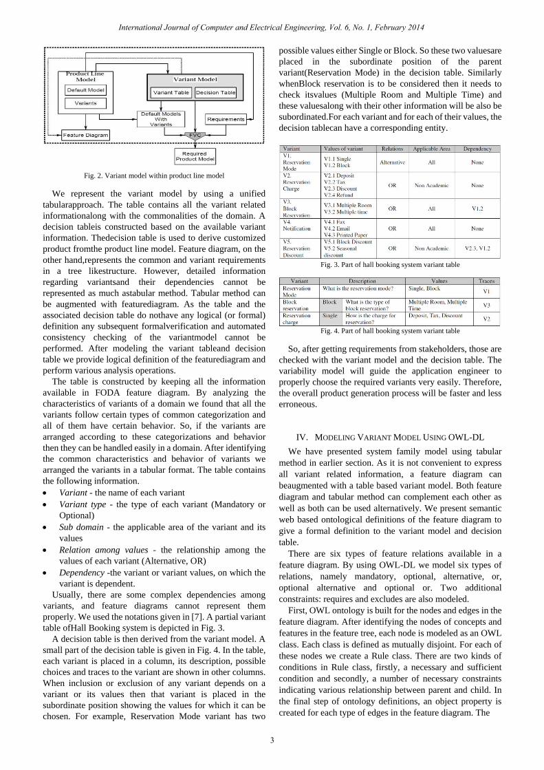
Fig. 2. Variant model within product line model
We represent the variant model by using a unified
tabularapproach. The table contains all the variant related
informationalong with the commonalities of the domain. A
decision tableis constructed based on the available variant
information. Thedecision table is used to derive customized
product fromthe product line model. Feature diagram, on the
other hand,represents the common and variant requirements
in a tree likestructure. However, detailed information
regarding variantsand their dependencies cannot be
represented as much astabular method. Tabular method can
be augmented with featurediagram. As the table and the
associated decision table do nothave any logical (or formal)
definition any subsequent formalverification and automated
consistency checking of the variantmodel cannot be
performed. After modeling the variant tableand decision
table we provide logical definition of the featurediagram and
perform various analysis operations.
The table is constructed by keeping all the information
available in FODA feature diagram. By analyzing the
characteristics of variants of a domain we found that all the
variants follow certain types of common categorization and
all of them have certain behavior. So, if the variants are
arranged according to these categorizations and behavior
then they can be handled easily in a domain. After identifying
the common characteristics and behavior of variants we
arranged the variants in a tabular format. The table contains
the following information.
Variant - the name of each variant
Variant type - the type of each variant (Mandatory or
Optional)
Sub domain - the applicable area of the variant and its
values
Relation among values - the relationship among the
values of each variant (Alternative, OR)
Dependency -the variant or variant values, on which the
variant is dependent.
Usually, there are some complex dependencies among
variants, and feature diagrams cannot represent them
properly. We used the notations given in [7]. A partial variant
table ofHall Booking system is depicted in Fig. 3.
A decision table is then derived from the variant model. A
small part of the decision table is given in Fig. 4. In the table,
each variant is placed in a column, its description, possible
choices and traces to the variant are shown in other columns.
When inclusion or exclusion of any variant depends on a
variant or its values then that variant is placed in the
subordinate position showing the values for which it can be
chosen. For example, Reservation Mode variant has two
possible values either Single or Block. So these two valuesare
placed in the subordinate position of the parent
variant(Reservation Mode) in the decision table. Similarly
whenBlock reservation is to be considered then it needs to
check itsvalues (Multiple Room and Multiple Time) and
these valuesalong with their other information will be also be
subordinated.For each variant and for each of their values, the
decision tablecan have a corresponding entity.
Fig. 3. Part of hall booking system variant table
Fig. 4. Part of hall booking system variant table
So, after getting requirements from stakeholders, those are
checked with the variant model and the decision table. The
variability model will guide the application engineer to
properly choose the required variants very easily. Therefore,
the overall product generation process will be faster and less
erroneous.
IV. MODELING VARIANT MODEL USING OWL-DL
We have presented system family model using tabular
method in earlier section. As it is not convenient to express
all variant related information, a feature diagram can
beaugmented with a table based variant model. Both feature
diagram and tabular method can complement each other as
well as both can be used alternatively. We present semantic
web based ontological definitions of the feature diagram to
give a formal definition to the variant model and decision
table.
There are six types of feature relations available in a
feature diagram. By using OWL-DL we model six types of
relations, namely mandatory, optional, alternative, or,
optional alternative and optional or. Two additional
constraints: requires and excludes are also modeled.
First, OWL ontology is built for the nodes and edges in the
feature diagram. After identifying the nodes of concepts and
features in the feature tree, each node is modeled as an OWL
class. Each class is defined as mutually disjoint. For each of
these nodes we create a Rule class. There are two kinds of
conditions in Rule class, firstly, a necessary and sufficient
condition and secondly, a number of necessary constraints
indicating various relationship between parent and child. In
the final step of ontology definitions, an object property is
created for each type of edges in the feature diagram. The
3
International Journal of Computer and Electrical Engineering, Vol. 6, No. 1, February 2014

TABLE I: SUMMARY OF OWL SYNTAX
Notation Explanation
⊤ Superclass of all OWL classes
𝐴 ⊑ 𝐵 A is a subclass of B
𝐴 ⊑ ¬𝐵 A and B are disjoint
𝐴 ⊓ 𝐵 Class intersection
𝐴 ⊔ 𝐵 Class union
𝐴 ≡ 𝐵 Class equivalence
⊤ ⊑ ∀𝑃 ⋅ 𝐴 Range of property is a class A
⊤ ⊑ ∃𝑃 ⋅ 𝐴 allValuesFrom/someValuesFrom restriction, giving the
class that for every instance of this class that has
instances of property P, all/some of the values of the
property are members of the class A
OWL syntax used in this paper is summarized in Table I.
For a parent feature 𝐴 and for each of its child features
𝐵1,𝐵2, . . . ,𝐵𝑛 the initial modeling produces the following
ontology,
𝐴 ⊑ ⊤
𝐴𝑅𝑢𝑙𝑒 ⊑ ⊤
𝑎𝑠𝐴 ⊑ 𝑂𝑏𝑗𝑒𝑐𝑡𝑃𝑟𝑜𝑝𝑒𝑟𝑡𝑦
⊤ ⊑ ∀𝑎𝑠𝐴 ·𝐴
𝐴𝑅𝑢𝑙𝑒 ≡ ∃𝑎𝑠𝐴 ·𝐴
𝐵𝑖 ⊑ ⊤
𝐵𝑖𝑅𝑢𝑙𝑒 ⊑ ⊤
𝑎𝑠𝐵𝑖 ⊑ 𝑂𝑏𝑗𝑒𝑐𝑡𝑃𝑟𝑜𝑝𝑒𝑟𝑡𝑦
⊤ ⊑ 𝑎𝑠𝐵𝑖 ·𝐵𝑖 𝐵𝑖𝑅𝑢𝑙𝑒 ≡ ∃𝑎𝑠𝐵𝑖 ·𝐵𝑖
𝐴 ⊑ 𝐵𝑖 𝑓𝑜𝑟 1 ≤ 𝑖 ≤ 𝑛
𝐵𝑖 ⊑ ¬𝐵𝑗 ,𝑓𝑜𝑟 1 ≤ 𝑖, 𝑗 ≤ 𝑛 ∧ 𝑖 ≠ 𝑗
Now we are ready to model the feature relations using the
ontology. Table II shows the OWL-DL representation of six
types of features and two constraints of a feature model.
TABLE II: OWL-DL REPRESENTATION OF VARIOUS TYPES OF FEATURES
V. FEATURE CONFIGURATION VERIFICATION
We input our ontology into Protégé and use RACER [12]
to check its consistency. For the initially encoded ontology,
RACER checks for consistency and show that encoded
definitions are consistent.
In feature modeling, an instance of a concept is a
configuration derived from the feature model. In order to
detect inconsistency in a configuration OWL classes are
used, and features and concept instances are then simulated.
When an instance is checked, the reasoner not only can check
inconsistency but also shows which class/classes are
inconsistent. We use an existential restriction for each feature
included in the configuration. For each feature 𝐵 available in
a feature diagram but not in its configuration, we use a
¬∃ 𝑎𝑠𝐵.𝐵 restriction to prevent the reasoning engine from
inferring the existence of this feature in the configuration.
If an instance 𝐶 of a concept derived from a feature
diagram with root concept 𝐴 and a set of features
𝐵1,𝐵2, . . . ,𝐵𝑖 assuming that they appear in the configuration
of 𝑋 and the features 𝐵𝑖 + 1, . . . ,𝐵𝑛 do not, the feature
configuration can be modeled as follows,
𝑋 ⊑ 𝐴𝑅𝑢𝑙𝑒
𝑋 ≡ ⨅(∃ 𝑎𝑠𝐵𝑗 ⋅ 𝐵𝑗 ,𝑓𝑜𝑟 1 ≤ 𝑗 ≤ 𝑖)) ⊓
⨅(¬∃𝑎𝑠𝐵𝑘 ⋅ 𝐵𝑘 ,𝑓𝑜𝑟 𝑖 < 𝑘 ≤ 𝑛)
Fig. 1. Partial feature tree with „Requires‟ relation
Let us consider a „requires‟ relation between the features
„Discount‟ and „Block‟from Reservation Mode. A part of the
figure is shown in Fig. 5 where the „requires‟ relation is
shown by using a dotted line from „Discount‟ to „Block‟.
𝐷𝑖𝑠𝑐𝑜𝑢𝑛𝑡𝑅𝑢𝑙𝑒 ⊑ ⊤ 𝐷𝑖𝑠𝑐𝑜𝑢𝑛𝑡𝑅𝑢𝑙𝑒 ≡ ∃𝑎𝑠𝐷𝑖𝑠𝑐𝑜𝑢𝑛𝑡 · 𝐷𝑖𝑠𝑐𝑜𝑢𝑛𝑡 𝐷𝑖𝑠𝑐𝑜𝑢𝑛𝑡𝑅𝑢𝑙𝑒 ⊑ ∃𝑎𝑠𝐵𝑙𝑜𝑐𝑘 · 𝐵𝑙𝑜𝑐𝑘
Suppose the configuration containing a concept instance 𝐸
and some features for the feature diagram in Fig. 5. We call
the instance node the class 𝐸. The feature „Block‟ requires
„Discount‟, but in the instances if „Block‟ is not selected the
reasoned tool shows the configuration is inconsistent.
𝐸 ≡ 𝐻𝑎𝑙𝑙𝐵𝑜𝑜𝑘𝑖𝑛𝑔 𝐸 ≡ ((∃𝑎𝑠𝑅𝑒𝑠𝑒𝑟𝑣𝐶𝑎𝑟𝑔𝑒 · 𝑅𝑒𝑠𝑒𝑟𝑣𝐶𝑎𝑟𝑔𝑒)
⊓ (∃𝑎𝑠𝐷𝑖𝑠𝑐𝑜𝑢𝑛𝑡 · 𝐷𝑖𝑠𝑐𝑜𝑢𝑛𝑡)⊓ (∃𝑎𝑠𝑅𝑒𝑠𝑒𝑟𝑣𝑀𝑜𝑑𝑒 · 𝑅𝑒𝑠𝑒𝑟𝑣𝑀𝑜𝑑𝑒) ⊓ (¬∃𝑎𝑠𝐵𝑙𝑜𝑐𝑘 · 𝐵𝑙𝑜𝑐𝑘))
4
International Journal of Computer and Electrical Engineering, Vol. 6, No. 1, February 2014

VI. RELATED WORK
Formal representation and verification of feature model is
a challenging task. Various formal approaches have been
adopted over the years for this purpose. Logic based
reasoning has played a major role so far for checking various
analysis operation [14], [15]. Propositional and First-Order
Logic (FOL) are being used in [16]–[20] to specify the
features and their relationships and constraints. Automated
tools [18], [21] based on such logic are also been developed
to automatically check feature consistency and valid
configuration of feature in SPL.
While most approaches applied FOL, very few used
semantic web and ontology to model and analyze feature
model. Semantic web not only provide semantic foundation
but also facilitates model creation, verification, integration
and maintenance. Similar to our approach OWL-DL is also
being used in [22, 23] to analyze feature diagram. Along with
modeling feature using OWL-DL both of them proposed
additional tool support to design feature models. Comparing
to these approaches we not only use OWL-DL not check
feature consistency, but also plan to check both domain and
product level feature configurations to check the analysis
operations suggested in [15].
VII. CONCLUSION
Successful development of software system families
requires appropriate organization and management of the
products involved. A significant characteristic of developing
system families is the management of common and variant
features, a crucial success factor of system family approach.
We presented a verification approach of product line model
by using semantic web technology. OWL-DL is used to
represent feature models and configuration in a concise and
unambiguous way. Features are represented as OWL classes
and relations as properties.
OWL ontologies provide a suitable platform for the
development of semantically aware software product line
allowing the knowledge within the feature model to be shared
among the reusable features of the SPL. We presented our
preliminary result of consistency checking using RACER. A
through consistency checking is currently undergoing. The
OWL-DL verification of the feature models of system family
gives confidence of our previously defined variability model.
We have focused on the modeling and verification of only
functional features of SPL. Non-functional requirements play
a crucial role in successful software development. Our future
plans include the incorporation of non-functional
requirement with functional requirement of a SPL and extend
our existing verification strategy to support both functional
and non-functional features. We are also interested in
web-services based product line management, the
orchestration of their feature as well as their feature
verification.
REFERENCES
[1] P. Clements and L. Northrop, Software Product Lines: Practices and
Patterns. 3rd ed. Addison-Wesley Professional, August 2001.
[2] D. L. Parnas, Software fundamentals. Boston, MA, USA:
Addison-Wesley Longman Publishing Co.,Inc., 2001, pp. 193–213.
[3] A. Hein, J. MacGregor, and S. Thiel, “Configuring software product
line features,” in Proc. the ECOOP 2001 Workshop on Feature
Interaction in Composed Systems, Budapest, Hungary, June 18-22,
2001, E. Pulvermuller, A. Speck, J. Coplien, M. D. Hondt, and W. D.
Meuter, Ed., vol. 2001-14, 2001, pp. 67–69.
[4] S. H. Ripon, K. H. Talukder, and M. K. I. Molla, “Modeling variability
for system families,” Malaysian Journal of Computer Science, vol. 16,
no. 1, 2003, pp. 37–46.
[5] S. Ripon, “A unified tabular method for modeling variants of software
product line,” in Pulvermuller, E., Speck, A., Coplien, J., Hondt, M.D.,
Meuter, W.D., ACM SIGSOFT Software Engineering Notes, Ed. vol.
37, no. 3, 2012, pp. 1–7.
[6] S. Zhang, W. Shen, and H. Ghenniwa, “A review of internet-based
product information sharing and visualization,” Computers in Industry,
vol. 54, no. 1, May 2004, pp. 1–15.
[7] I. Horrocks, P. F. Patel-Schneider, and F. V. Harmelen, “From shiq and
rdf to owl: Themaking of a web ontology language,” Journal of Web
Semantics 1, vol. 1, no. 1, Dec. 2003, pp. 7-26.
[8] F. Baader, D. Calvanese, D. L. McGuinness, D. Nardi, and P. F.
Patel-Schneider, The Description Logic Handbook: Theory,
Implementation, and Applications, Ed., NY, USA: Cambridge
University Press, 2003.
[9] J. S. Dong, C. H. Lee, H. B. Lee, Y. F. Li, and H. Wang, “A combined
approach to checking web ontologies,” in Proc. the 13th international
conference on World Wide Web. WWW ’04, NY, USA: ACM, 2004,
pp. 714–722.
[10] D. Berardi, “Using dls to reason on uml class diagrams,” in Proc.
Workshop on Applications of Description Logics, 2002, pp. 1–11.
[11] N. F. Noy, M. Sintek, S. Decker, M. Crubezy, R. W. Fergerson, and M.
A. Musen, “Creating semantic web contents with protege-2000,” IEEE
Intelligent Systems, 2001, pp. 60–71.
[12] V. Haarslev and R. Muller, Racer user’s Guide and Reference Manual
- Version 1.7.6, 2002.
[13] K. Czarnecki and U. W. Eisenecker, Generative Programming:
Methods, Tools, and Applications. NY, USA: ACM
Press/Addison-Wesley Publishing Co., 2000.
[14] D. S. Batory, “Feature models, grammars, and propositional formulas,”
LNCS, J. H. Obbink, K. Pohl, Ed., SPLC., vol. 3714, Springer, 2005, pp.
7–20.
[15] D. Benavides, A. R. Cortés, P. Trinidad, and S. Segura, “A survey on
the automated analyses of feature models,” JISBD, 2006, pp. 367–376.
[16] S. Ripon, K. Azad, S. J. Hossain, and M. Hassan, “Modeling and
analysis of product line variants,” in Proc. the 16th International
Software Product Line Conference, vol. 2, New York, NY, USA: ACM,
2012, pp. 26–31.
[17] M. Mannion, “Using first-order logic for product line model validation,”
in Proc. the Second International Conference on Software Product
Lines, London, UK: Springer-Verlag, 2002, pp. 176–187.
[18] J. Sun, H. Zhang, and H. Wang, “Formal semantics and verification for
feature modeling,” in Proc. the 10th IEEE International Conference on
Engineering of Complex Computer Systems, Washington, DC, USA:
IEEE Computer Society, 2005, pp. 303–312.
[19] D. Benavides, P. Trinidad, and A. Ruiz-Cortés, “Automated reasoning
on feature models,” in Proc. the 17th international conference on
Advanced Information Systems Engineering, Berlin, Heidelberg:
Springer-Verlag, 2005, pp. 491–503.
[20] W. Zhang, H. Zhao, and H. Mei, “A Propositional Logic-Based
Method for Verification of Feature Models,” J. Davies, W. Schulte, M.
Barnett, Ed., Formal Methods and Software Engineering, vol. 3308 of
LNCS, Springer Berlin / Heidelberg, 2004, pp. 115–130.
[21] P. Trinidad, D. Benavides, A. Ruiz-Cortés, S. Segura, and A. Jimenez,
“Fama framework,” in Proc. the 2008 12th International Software
Product Line Conference, Washington, DC, USA: IEEE Computer
Society, 2008, pp. 359.
[22] H. H. Wang, Y. F. Li, J. Sun, H. Zhang, and J. Pan, “Verifying feature
models using owl,” Web Semant, vol. 5, no. 2, June 2007, pp. 117–129.
[23] M. Noorian, A. Ensan, E. Bagheri, H. Boley, and Y. Biletskiy, “Feature
model debugging based on description logic reasoning,” DMS,
Knowledge Systems Institute, 2011, pp. 158–164.
Shamim Ripon is an assistant professor in the
Department of Computer Science and Engineering, East
West University, Dhaka, Bangladesh where he leads
Software Engineering and Formal Method Research
Group. Previously, he was a Research Associate in the
Department of Computing Science, University of York,
UK and Research Fellow in the Department of
Computing Science, University of Glasgow, UK. He
also served as a Lecturer in Khulna University, Bangladesh. He is a member
5
International Journal of Computer and Electrical Engineering, Vol. 6, No. 1, February 2014
of IAENG, Senior member of IACSIT.
Dr. Ripon holds a B.Sc. in Computer Science and Engineering from
Khulna University, M.Sc. in Computer Science from National University of
Singapore and PhD in Computer Science from University of Southampton,
UK. His research interests focus on the Requirement Engineering, Software
Product Line, Semantic Web, Natural Language Processing. His current
research examines the formal representation and verification of knowledge
based requirement specification..
Moshiur Mahamud Piash is a B.Sc. final year student
in the Department of Computer Science and
Engineering, East West University, Dhaka, Bangladesh
where he is involved in the Software Engineering and
Formal Method Research Group.
Mr. Piash is currently working in the product line
based requirement verification using semantic web. His
is also interested in Web services and Intelligent Agent.
Sheikh Md. Alam Hossainis a B.Sc. final year student
in the Department of Computer Science and
Engineering, East West University, Dhaka,
Bangladesh where he is involved in the Software
Engineering and Formal Method Research Group.
Mr. Alam is currently working in the product line
based requirement verification using semantic web.
His research interests include Web services and
Knowledge Based Software Engineering .
Mohammed Salah Uddin is a B.Sc. final year student in
the Department of Computer Science and Engineering,
East West University, Dhaka, Bangladesh where he is
involved in the Software Engineering and Formal
Method Research Group.
Mr. Salah Uddin is currently working towards formal
verification of web services composition. He is also
interested in semantic web based requirement analysis of
product line requirements.
6
International Journal of Computer and Electrical Engineering, Vol. 6, No. 1, February 2014