Embed Size (px)
Citation preview

ENGLISH (non-US)
OTH-SEM-IFU-MULTI-LANG-0123 Rev H
SEM Scanner 200
(SW V3.60)
Instructions for Use

ENGLISH (non-US)
Page 2 of 35
OTH-SEM-IFU-MULTI-LANG-0123 Rev H
Table of Contents 1. Warnings and Safety Precautions ......................................................................................................... 4
2. General ....................................................................................................................................................... 6
2.1 Nomenclature .............................................................................................................................. 6
2.2 Indications for Use ...................................................................................................................... 6
2.3 Device Description ..................................................................................................................... 6
2.3.1 SEM Scanner 200 Device ........................................................................................................... 7
2.3.2 SEM Scanner 200 Display .......................................................................................................... 8
2.4 Additional SEM Scanner 200 Components ........................................................................... 9
2.5 Contraindications ........................................................................................................................ 9
2.6 Intended User Profile ................................................................................................................. 9
2.7 Adverse Events ............................................................................................................................ 9
2.8 Warranty and Disclaimer .......................................................................................................... 9
2.9 Table of Symbols ...................................................................................................................... 11
3. Operating Instructions ......................................................................................................................... 12
3.1. Unpacking and Inspection ....................................................................................................... 12
3.2. Charging the Device ................................................................................................................ 12
3.3. Use of Device ............................................................................................................................ 14
3.4. Acquiring SEM Scanner 200 Readings .................................................................................. 16
3.5. Displaying an Assessment from a Set of Readings ............................................................ 18
3.6. Clinical Interpretation ............................................................................................................. 18
3.6.1. Interpretation of the ∆ Symbol ............................................................................................. 18
3.6.2. Deriving SEM Scanner Delta (∆) Values – A Prospective Clinical Study (SEM200-008) ............................................................................................................................................. 18
3.6.3. SEM200-008 – Study Population ........................................................................................... 19
3.6.4. SEM200-008 – Results ............................................................................................................. 20
3.7. Recommended SEM Scanner 200 Readings at the Sacrum ............................................. 22
3.8. Recommended SEM Scanner 200 Readings at the Heels ................................................ 23
3.9. Recommended SEM Scanner 200 Readings at Other Body Locations ........................ 25

ENGLISH (non-US)
Page 3 of 35
OTH-SEM-IFU-MULTI-LANG-0123 Rev H
3.10. Resetting the SEM Scanner 200 ............................................................................................ 25
3.11. Ending SEM Scanner 200 Operation .................................................................................... 26
3.12. Summary of Action Button Functions ................................................................................. 26
4. Cleaning and Disinfection ................................................................................................................... 27
Cleaning and Disinfection Overview .............................................................................................. 27
Scanner Cleaning and Disinfection Instructions ........................................................................... 27
5. Troubleshooting .................................................................................................................................... 29
6. Guidance and Manufacturer’s Declaration – Electromagnetic Emissions ................................ 30
6.1. Electromagnetic Environment ............................................................................................... 30
6.2. Electromagnetic Immunity ...................................................................................................... 31
6.3. Separation Distance ................................................................................................................. 33
7. Specifications .......................................................................................................................................... 34
ENGLISH (non-US)
Page 4 of 35
OTH-SEM-IFU-MULTI-LANG-0123 Rev H
1. Warnings and Safety Precautions The SEM Scanner 200 has been designed and constructed in accordance with the European Medical Device Directives, applicable U.S. regulations and requirements, as well as U.S. and international standards for operation of electrical equipment, electromagnetic compatibility, and stipulated safety requirements.
Improper use or handling, however, can result in damage and/or injury. To prevent damage to the equipment, please read these operating instructions carefully before using your SEM Scanner 200 system. Keep these instructions in a safe place. Follow the instructions below to ensure safe and trouble-free operation of your system.
Caution: Federal (US) law restricts this device to sale by or on the order of a physician or other licensed health practitioner.
WARNINGS:
• WARNING: To prevent the spread of infection, the SEM Scanner 200 should be properly cleaned and disinfected according to the instructions provided in this Instructions for Use after it is used on a patient.
• WARNING: Should the device come in contact with non-sterile surfaces (for example, if it falls on the floor) it should be cleaned and disinfected before obtaining another patient reading.
• WARNING: Do not attempt to disassemble or otherwise modify the SEM Scanner 200 as this can result in unintended hazards. The SEM Scanner 200 can only be serviced by the manufacturer (Bruin Biometrics, BBI) or a BBI Authorized Service Center. Please contact your BBI Product Specialist or Customer Service regarding any device that is not functioning correctly.
• WARNING: To avoid the risk of electric shock, this equipment must only be connected to a supply main with protective earth.
• WARNING: To avoid the risk of explosion, the SEM Scanner 200 should not be used in the presence of flammable anesthetic agents.

ENGLISH (non-US)
Page 5 of 35
OTH-SEM-IFU-MULTI-LANG-0123 Rev H
CAUTIONS:
• CAUTION: Examine the SEM Scanner 200 for damage or sharp edges prior to each use. If any damage or sharp edges are found, please contact Customer Service or your Product Specialist. Do not attempt to use the device.
• CAUTION: Check the SEM Scanner 200 is turned OFF before returning to the Charging Mat for recharging. If the SEM Scanner is not turned OFF, the device may be warmer than normal to the touch after it is recharged.
ENGLISH (non-US)
Page 6 of 35
OTH-SEM-IFU-MULTI-LANG-0123 Rev H
2. General
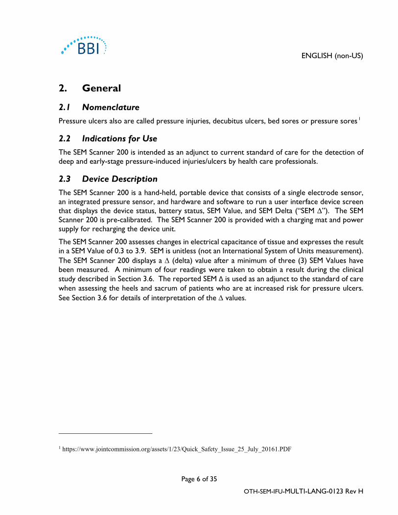
2.1 Nomenclature Pressure ulcers also are called pressure injuries, decubitus ulcers, bed sores or pressure sores 1
2.2 Indications for Use The SEM Scanner 200 is intended as an adjunct to current standard of care for the detection of deep and early-stage pressure-induced injuries/ulcers by health care professionals.
2.3 Device Description The SEM Scanner 200 is a hand-held, portable device that consists of a single electrode sensor, an integrated pressure sensor, and hardware and software to run a user interface device screen that displays the device status, battery status, SEM Value, and SEM Delta (“SEM ∆”). The SEM Scanner 200 is pre-calibrated. The SEM Scanner 200 is provided with a charging mat and power supply for recharging the device unit.
The SEM Scanner 200 assesses changes in electrical capacitance of tissue and expresses the result in a SEM Value of 0.3 to 3.9. SEM is unitless (not an International System of Units measurement). The SEM Scanner 200 displays a ∆ (delta) value after a minimum of three (3) SEM Values have been measured. A minimum of four readings were taken to obtain a result during the clinical study described in Section 3.6. The reported SEM Δ is used as an adjunct to the standard of care when assessing the heels and sacrum of patients who are at increased risk for pressure ulcers. See Section 3.6 for details of interpretation of the ∆ values.
1 https://www.jointcommission.org/assets/1/23/Quick_Safety_Issue_25_July_20161.PDF

ENGLISH (non-US)
Page 7 of 35
OTH-SEM-IFU-MULTI-LANG-0123 Rev H
2.3.1 SEM Scanner 200 Device
Action button (turns device on and off and resets readings)
Figure 1. SEM Scanner 200 Top View showing Display and Action Button
Figure 2. The electrode on the bottom of the SEM Scanner 200
Figure 3. SEM Scanner 200 Side View
ENGLISH (non-US)
Page 8 of 35
OTH-SEM-IFU-MULTI-LANG-0123 Rev H
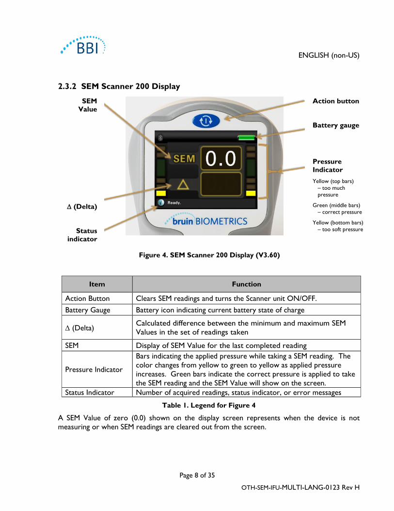
2.3.2 SEM Scanner 200 Display
SEM Value
∆ (Delta)
Status indicator
Action button
Battery gauge
Pressure Indicator Yellow (top bars)
– too much pressure
Green (middle bars) – correct pressure
Yellow (bottom bars) – too soft pressure
Figure 4. SEM Scanner 200 Display (V3.60)
Item Function
Action Button Clears SEM readings and turns the Scanner unit ON/OFF. Battery Gauge Battery icon indicating current battery state of charge
∆ (Delta) Calculated difference between the minimum and maximum SEM Values in the set of readings taken
SEM Display of SEM Value for the last completed reading
Pressure Indicator
Bars indicating the applied pressure while taking a SEM reading. The color changes from yellow to green to yellow as applied pressure increases. Green bars indicate the correct pressure is applied to take the SEM reading and the SEM Value will show on the screen.
Status Indicator Number of acquired readings, status indicator, or error messages
Table 1. Legend for Figure 4
A SEM Value of zero (0.0) shown on the display screen represents when the device is not measuring or when SEM readings are cleared out from the screen.

ENGLISH (non-US)
Page 9 of 35
OTH-SEM-IFU-MULTI-LANG-0123 Rev H
2.4 Additional SEM Scanner 200 Components The SEM Scanner 200 ships with an Inductive Charging Mat and wall-mount power supply that is used when charging the device.
Figure 5. Inductive Charging Mat
2.5 Contraindications Do not use on broken skin.
2.6 Intended User Profile The system is intended for use by healthcare professionals.
2.7 Adverse Events No known adverse events.
2.8 Warranty and Disclaimer Bruin Biometrics LLC (BBI) warrants the SEM Scanner 200 against defects in materials and workmanship for three (3) years from the date of purchase from BBI or its subsidiaries. This warranty is given only to the original purchaser of the SEM Scanner 200. BBI’s obligation under the warranty is to provide for repair, or at its option, to provide a replacement product. No other remedy is obligated by this warranty. All special, incidental, and coincidental damages are excluded.
To request repair or replacement under this warranty, purchasers should contact their local Customer Service provider.
Warranty conditions may differ in some countries. Contact your Customer Service provider for warranty terms.

ENGLISH (non-US)
Page 10 of 35
OTH-SEM-IFU-MULTI-LANG-0123 Rev H
Risk of loss or damage during shipments under this warranty shall be borne by the party shipping the Product. Products shipped by the Purchaser under this warranty shall be suitably packaged to protect the Product. If Purchaser ships a product to BBI in unsuitable packaging, any physical damage present in the Product on receipt and inspection by BBI, and not previously reported, will be presumed to have occurred in transit and will be the responsibility of the Purchaser.
Exclusions
This warranty is limited to defects and materials that can be attributed to a fault or defect within the SEM Scanner 200.
This warranty does not extend to any Warranted Products or parts thereof: (a) that have been subject to misuse, neglect or accident, (b) that have been damaged by causes external to the Warranted Product, (c) that have been used in violation of the BBI Instructions for Use, (d) on which the serial number has been removed or made illegible, (e) that have been modified by anyone other than BBI or its authorized service center, unless authorized prior to such service by BBI, (f) that are equipment sold as used, or (g) that are exposed to agents listed in Table 2, below. Table 2 is not an exhaustive list of agents which may compromise the integrity of the SEM Scanner 200.
Severe Effect – NOT Recommended Benzene Cyclohexane Kerosene Nitric Acid – 70% Carbon tetrachloride Ethyl Chloride Trichloroethylene Perchloroethylene Chlorobezene Freon Lacquer Toluene Chloroform Gasoline, unleaded Naphtha Xylene
Table 2. Agents That Should Never Be Used on The SEM Scanner 200
Disclaimer of Additional Warranties
No distributor, dealer or other party is authorized to make any warranty on behalf of BBI, or to assume for BBI any other liability with respect to the SEM Scanner 200.
The contents of these Instructions for Use do not constitute a warranty.

ENGLISH (non-US)
Page 11 of 35
OTH-SEM-IFU-MULTI-LANG-0123 Rev H
2.9 Table of Symbols
Symbol Meaning
Manufacturer’s Catalog designation or number
Contact/European Representative of manufacturer
Dispose of this equipment according to local regulations for electrical and electronic
waste disposal
Instructions are included and must be followed
Serial number
Drip Proof Equipment-IPX1: The SEM Scanner 200 enclosure provides protection against the harmful effects of the ingress of liquids. (IPX1, per IEC 60529)
Caution or warning
CE mark in accordance to the European Medical Device Directive
Manufactured By
Type BF Applied Part with IEC-60601-1
CAUTION: Federal (USA) law restricts this device to sale by or on the order of a
physician or other licensed health practitioner
Keep away from sunlight
Keep dry
Do not use if package is damaged and the device inside appears physically broken,
cracked, or does not charge and initialize following the Instructions for Use
Temperature limit
Humidity limit
Table 3. Table of Symbols

ENGLISH (non-US)
Page 12 of 35
OTH-SEM-IFU-MULTI-LANG-0123 Rev H
3. Operating Instructions
3.1. Unpacking and Inspection After the SEM Scanner 200 is unpacked verify that the scanner has no signs of damage. If there are signs of damage, contact Customer Service.
3.2. Charging the Device The device must be charged before using it for the first time, leave the device on the charging mat for at least 6 hours to completely charge the battery prior to initial use.
The device also needs to be charged if the SEM Scanner 200 screen displays a red, low battery icon (Figure 6).
Low battery
Figure 6. The battery gauge is in the upper- right corner of the SEM Scanner Display

ENGLISH (non-US)
Page 13 of 35
OTH-SEM-IFU-MULTI-LANG-0123 Rev H
Follow the steps below to charge the device:
1. Connect the charging mat power adaptor to the power outlet.
2. Ensure that the SEM Scanner 200 is OFF by pressing and holding the Action Button
for 6 seconds until the display screen is blank. 3. Turn the SEM Scanner 200 upside down (so the electrode is on top) and press it firmly
into the cradle on the charging mat (Figure 7). 4. A blue charging mat indicator light indicates that it is charging the SEM Scanner 200. If the
blue light is not illuminated, then the SEM Scanner 200 may not be positioned securely in the cradle. Do not press the Action Button to turn the SEM Scanner 200 on while it is on the charging mat.
When fully charged, the battery provides for approximately three hours of SEM Scanner 200 accumulated operation.
Exposed electrode
SEM cradle
Power cord
Blue charging indicator light
Figure 7. Correct positioning of the SEM Scanner 200 on the charging mat

ENGLISH (non-US)
Page 14 of 35
OTH-SEM-IFU-MULTI-LANG-0123 Rev H
3.3. Use of Device The SEM Scanner 200 should be properly cleaned and disinfected after it is used on a patient. The SEM Scanner 200 must be fully dry after cleaning and disinfection prior to use. See Section 4 for detailed cleaning and disinfection instructions.
Follow the steps below to start a session:
1. Remove the SEM Scanner 200 from the charging mat.
2. Verify the scanner has no visible damages or sharp edges and that the electrode is sealed against the base. Do not use the device if the electrode seal is broken or any damage or sharp edges are found.
3. Turn the SEM Scanner 200 on by pressing the Action Button for approximately one second (Figure 8).
Figure 8. Starting a Session
3.1 After turning on the SEM Scanner 200,
an audio tone will sound and the initialization screen will be displayed (Figure 9).
It is important that the SEM Scanner 200 electrode remains untouched during initialization. See display, “Do Not Touch Electrode Until Device Ready”.
If the electrode is touched during initialization, turn off the device and turn on the device to re-initialize.
ENGLISH (non-US)
Page 15 of 35
OTH-SEM-IFU-MULTI-LANG-0123 Rev H
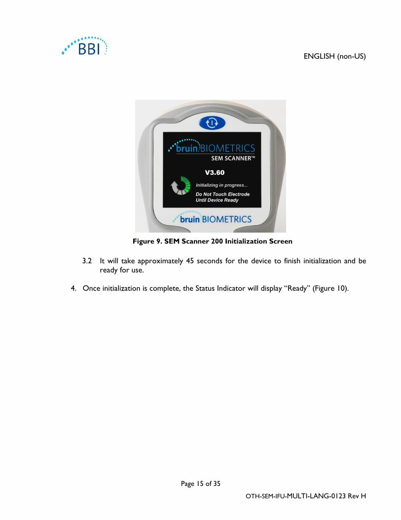
Figure 9. SEM Scanner 200 Initialization Screen
3.2 It will take approximately 45 seconds for the device to finish initialization and be ready for use.
4. Once initialization is complete, the Status Indicator will display “Ready” (Figure 10).
ENGLISH (non-US)
Page 16 of 35
OTH-SEM-IFU-MULTI-LANG-0123 Rev H
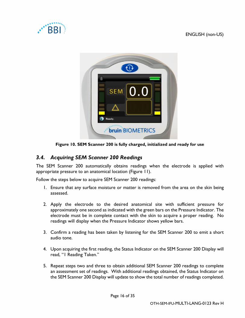
Figure 10. SEM Scanner 200 is fully charged, initialized and ready for use
3.4. Acquiring SEM Scanner 200 Readings The SEM Scanner 200 automatically obtains readings when the electrode is applied with appropriate pressure to an anatomical location (Figure 11).
Follow the steps below to acquire SEM Scanner 200 readings:
1. Ensure that any surface moisture or matter is removed from the area on the skin being assessed.
2. Apply the electrode to the desired anatomical site with sufficient pressure for approximately one second as indicated with the green bars on the Pressure Indicator. The electrode must be in complete contact with the skin to acquire a proper reading. No readings will display when the Pressure Indicator shows yellow bars.
3. Confirm a reading has been taken by listening for the SEM Scanner 200 to emit a short audio tone.
4. Upon acquiring the first reading, the Status Indicator on the SEM Scanner 200 Display will read, “1 Reading Taken.”
5. Repeat steps two and three to obtain additional SEM Scanner 200 readings to complete an assessment set of readings. With additional readings obtained, the Status Indicator on the SEM Scanner 200 Display will update to show the total number of readings completed.

ENGLISH (non-US)
Page 17 of 35
OTH-SEM-IFU-MULTI-LANG-0123 Rev H
6. See Section 3.5 for details on display when completing an assessment set of readings.
7. See Sections 3.7 and 3.8 for recommendations of number of SEM readings to complete
for an assessment.
8. Reset the SEM Scanner 200 between each anatomical location and patient. Pressing the
Action Button for approximately one second will clear the numbers from the display. The display will show a value of zero (0.0) for the SEM Value (see Figure 10 and see Section 3.9). If the SEM Scanner 200 is not reset to zero (0.0), the ∆ value from
the previous evaluation (anatomical location or prior patient) could be used to calculate the ∆ value on the next anatomical location or patient. This will give you a wrong ∆ value for that evaluation.
9. To minimize skin irritation from exposure to the cleaning and disinfecting agent, users
should use gloves and wear an apron when cleaning and disinfecting the device between uses. Users should always follow cleaning agent manufacturers’ instructions. Users may also clean patients’ assessed anatomical locations after scanning in accordance with your facility’s procedure for cleaning patients skin surfaces.
10. Check that the device has been reset before cleaning and disinfecting the device. Perform cleaning and disinfection procedure between each patient. See Section 4 for Cleaning and Disinfection Instructions.
Figure 11. SEM Scanner Acquiring Heel Reading

ENGLISH (non-US)
Page 18 of 35
OTH-SEM-IFU-MULTI-LANG-0123 Rev H
3.5. Displaying an Assessment from a Set of Readings The SEM Scanner 200 records values in sample sets according to the number of readings taken during an assessment. In an assessment set of readings, the difference between the largest (high) reading and smallest (low) reading is displayed on the SEM Scanner 200 display as a symbol “∆” (delta). Each time a new reading is taken the SEM value, ∆ value, and the number of readings will be updated and displayed by the SEM Scanner 200.
The ∆ symbol will display a value when a minimum of three (3) SEM Scanner 200 patient readings are performed. A minimum of four readings were taken to obtain a result during the clinical study described in Section 3.6. See Section 3.6 for clinical interpretation recommendations.
3.6. Clinical Interpretation Clinical interpretation of SEM Scanner 200 readings begins by collecting a set of readings described in Section 3.4 performed on each anatomical site under assessment. After the set of readings have been collected for the assessment, the ∆ symbol will display a value as described in Section 3.5.
3.6.1. Interpretation of the ∆ Symbol
A ∆ < 0.6 at an anatomical site may suggest the tissue is at lower risk for pressure ulcers
A ∆ ≥ 0.6 at an anatomical site may suggest increased risk for pressure ulcers
WARNING: The standard of care should be followed for reducing the risk of developing pressure ulcers. Readings from the SEM Scanner 200 can be used to support increased intervention, but should never be to the basis for decreasing intervention.
WARNING: This device is not intended to be used for detecting or diagnosis of pressure ulcers.
3.6.2. Deriving SEM Scanner Delta (∆) Values – A Prospective Clinical Study (SEM200-008)
Clinical study (SEM200-008 or “008”) results from 182 study subjects with 437 anatomical locations were used to derive clinical validity of the SEM Scanner delta values. The 008 clinical study was a prospective, blinded study comparing the SEM Scanner to the current Standard of Care, Visual Skin Assessment (VSA), in identifying patients with tissue at increased risk of developing pressure ulcers at the heels or sacrum. SEM Scanner assesses the electrical capacitance of skin and tissue below the electrode when placed on the patient’s skin. VSA seeks to identify PUs (stage 1 and beyond) once they are visible at the skin level.

ENGLISH (non-US)
Page 19 of 35
OTH-SEM-IFU-MULTI-LANG-0123 Rev H
3.6.3. SEM200-008 – Study Population The SEM200-008 (008) clinical study was a prospective, blinded study designed to evaluate the SEM Scanner relative to the current Standard of Care, Visual Skin Assessment (VSA), for identifying patients with skin and tissue at increased risk of developing pressure ulcers at the heels or sacrum. In the 008 Study there were 12 unique clinical-trial sites in the United States and United Kingdom that were included in the study. Each had their own Principal Investigator. Subjects in the 008-study received standard-of-care interventions for pressure ulcer prevention and management. These subjects were at varying risk for developing pressure ulcers (PUs) (as defined by current risk assessment tools) and thus interventions were given.
According to the study protocol’s inclusion criteria, these patients were defined as being “at risk” if they met one of the following criteria:
• PU Risk Score – Braden < 15; Waterlow ≥ 10; or Norton ≤ 18;
• Poor mobility; e.g., Braden mobility subscore ≤2; Waterlow mobility subscore >2; Norton mobility subscore ≤2; or poor mobility according to clinical judgment (chair- or bed-bound);
• Poor nutrition; e.g., Braden nutrition subscore ≤2; Waterlow nutrition subscore >2; or other indicator of poor nutrition; and/or
• Medical procedure (e.g., surgery, x-ray, etc.) involving immobility and inability to change position lasting 4 hours or longer.
Specifically, 182 patients were listed as Intent to Treat (ITT). Of those, 170 Patients were included in the sensitivity and specificity calculations with 48 pressure ulcers forming across 36 Patients.
Within the 12 sites included in the study, the trials were completed in:
1. Orthopaedic Trauma: 14% (n=26 subjects) 2. Medical Surgery: 27% (n=50 subjects) 3. Long Term Care: 32% (n=58 subjects) 4. ICU: 9% (n=17 subjects) 5. Rehab: 4% (n=7 subjects) 6. Neurologic Care: 8% (n=15 subjects) 7. Other/Mixed: 5% (n=9 subjects)

ENGLISH (non-US)
Page 20 of 35
OTH-SEM-IFU-MULTI-LANG-0123 Rev H
3.6.4. SEM200-008 – Results Sensitivity and specificity data presented in Table 4 and Table 5 show how the SEM Scanner 200 compares to visual skin assessment in identifying patients with tissue at risk of developing pressure ulcers at the heels or sacrum.
48 PUs developed in the Intent-to-Treat population (26% incidence in the ITT population) with a number of patients developing at least 1 PU at separate anatomical sites. Therefore the 48 PUs developed on 36 patients.
In the 008 study, healthcare providers assessed 437 individual anatomical locations from 182 subjects in the ITT. These locations were classed as shown in Table 4. Results from the 008 clinical study results from each assessed anatomy were classed as:
• True positives - a visible pressure ulcer and a localized SEM delta of 0.6 or above (“abnormal levels of SEM”). Table 4 shows 42 anatomical sites in this category.
• True negatives - no visible pressure ulcer and a localized SEM delta below 0.6 (“flat values”). Table 4 shows 128 anatomical sites in this category.
• False negatives - a visible pressure ulcer and a localized SEM delta below 0.6 (“flat values”). Table 4 shows 6 anatomical sites in this category.
• False positives - no visible pressure ulcer and a localized SEM delta of 0.6 or above (“abnormal levels of SEM”). Table 4 shows 261 anatomical sites in this category.
Total Patients in ITT Population (182) / Total
Anatomical Locations (437) Visible Pressure Ulcer No Visible Pressure
Ulcer
SEM Δ ≥ 0.6 42 261
SEM Δ < 0.6 6 128
Table 4. Final results for individual anatomical locations for SEM Scanner from the 008 study
In order to appropriately account for the within subject correlation in the estimates of the 95% confidence intervals for sensitivity and specificity, the bootstrap method used. The bootstrap method was applied by sampling, with replacement, from the original dataset. The sampling was done on a per subject basis such that all records for a randomly chosen subject were

ENGLISH (non-US)
Page 21 of 35
OTH-SEM-IFU-MULTI-LANG-0123 Rev H
extracted. One thousand datasets were generated using this method, each with the same number of subjects as the original dataset.
Estimates of sensitivity and specificity were then calculated across datasets by taking the median value. The confidence limits were generated from the 2.5th and 97.5th percentiles. This resulted in the following estimates (Table 5).
Sensitivity1 Specificity1
SEM ∆ n % 95% CI n % 95% CI
≥0.6 42 87.4% 77.8%, 96.7% 124 33.0% 27.6%, 38.7%
1 Sensitivity and specificity analysis was performed following an analysis rule of 2 of 3 consecutive observations of a SEM delta of 0.6 or above (“SEM positive”) or SEM delta less than 0.6 (“SEM negative”) from a five-day window from study exit or when a pressure ulcer is identified by visual skin assessment. This analysis rule was defined before study analysis was performed.
Table 5. Range of SEM ∆ and Confidence Intervals Using Bootstrap Method
The ∆ value should be considered in conjunction with other measures of standard of care and clinical judgment.

ENGLISH (non-US)
Page 22 of 35
OTH-SEM-IFU-MULTI-LANG-0123 Rev H
3.7. Recommended SEM Scanner 200 Readings at the Sacrum The recommended positions for SEM Scanner 200 readings to complete for an assessment of the sacrum is shown in Figure 12.
Readings are taken by moving directionally around the bony prominence to identify healthier tissue and other damaged areas around the bony prominence.
For the sacrum, SEM Scanner readings needed for clinical interpretation are taken at six (6) points as shown in Figure 12 and as described below. SEM Scanner readings do not need to be taken in numerical sequence.
As a starting point, Reading 1 begins just above the gluteal cleft of the sacrum, around S3 of the sacral bone (marked with the number 1 in Figure 12).
Readings 2 to 6 are positioned side-by-side from Reading 1. Variations with distances apart may arise due to positioning of the patient and restrictions prohibiting measurements at positions 5 and 6.
Reading 3 should not measure higher than S1 of the sacral bone.
Figure 12. SEM Scanner 200 readings over and around sacrum

ENGLISH (non-US)
Page 23 of 35
OTH-SEM-IFU-MULTI-LANG-0123 Rev H
SEM Scanner 200 Readings - Sacrum
∆ Calculations
3 2.0
High 2.7
5 2.4
2 2.7
1 1.8
4 2.6
6 2.0
Low 1.8
∆ 0.9
Table 6. Example of SEM Scanner 200 Readings for Sacrum
3.8. Recommended SEM Scanner 200 Readings at the Heels The recommended positions for SEM Scanner 200 readings to complete for an assessment of the heel is shown in Figure 13. Readings are taken by moving directionally around the bony prominence to identify healthier tissue and other damaged areas around the bony prominence.
For the heel(s), BBI recommends taking SEM Scanner 200 readings at the four (4) points as shown in Figure 13 and described below. Readings at these four points were taken for the clinical study described in Section 3.6. SEM Scanner readings do not need to be taken in numerical sequence.
If, however, one of the Reading points is calloused, do not take a reading at that spot. The SEM Scanner will produce an SEM Δ reading after only three (3) readings.

ENGLISH (non-US)
Page 24 of 35
OTH-SEM-IFU-MULTI-LANG-0123 Rev H
Reading #1: Back of the heel around the calcaneus. Avoid placing the SEM Scanner on the achilles tendon.
Reading #2: Lateral side of the heel. Lateral side is the same side as the little toe (fifth toe). Avoid placement of the SEM Scanner on the lateral malleolus
Reading #3: Medial side of the heel. Medial side is the same side as the big toe (first toe). Avoid placement of the SEM Scanner on the medial malleolus.
Reading #4: Heel pad (sole of the heel) from the back edge of the heel.
Figure 13. SEM Scanner 200 readings over and around the heel

ENGLISH (non-US)
Page 25 of 35
OTH-SEM-IFU-MULTI-LANG-0123 Rev H
SEM Scanner 200 Readings – Heel
∆ Calculations
2 2.2
4 2.4 3
2.4
High 2.4
1 2.1
Low 2.1
∆ 0.3
Table 7. Example of SEM Scanner 200 Readings for the Heel
3.9. Recommended SEM Scanner 200 Readings at Other Body Locations The SEM Scanner may be useful in tracking SEM values at alternate anatomical locations over time. For these locations, the SEM deviation for action may be different than for heels and sacrum and is at clinician discretion.
3.10. Resetting the SEM Scanner 200 To clear (resetting) the sample set and start recording readings for a new sample set, select and
hold the Action Button for one second (Figure 14). The display screen will show zero (0.0) for SEM and no values for ∆.
0.0

ENGLISH (non-US)
Page 26 of 35
OTH-SEM-IFU-MULTI-LANG-0123 Rev H
Figure 14. Resetting the SEM Scanner 200 to zero
3.11. Ending SEM Scanner 200 Operation
To end SEM Scanner 200 operation, press and hold the Action Button for approximately 6 seconds until the SEM Scanner screen becomes blank. The SEM Scanner 200 operation is now ended and power is off.
3.12. Summary of Action Button Functions
Desired SEM Scanner Action
Approximate Time to Hold Action Button Result
Start Operation 1 second Turns the power on. SEM Scanner 200 will begin initialization when the button is released.
Stop Operation 6 seconds Turns the power off. SEM Scanner 200 screen will be blank.
Clear Results 1 second Resets the SEM value to zero (0.0) and ∆ value with no numbers displayed on the screen.
Table 8. Summary of Action Button Functions

ENGLISH (non-US)
Page 27 of 35
OTH-SEM-IFU-MULTI-LANG-0123 Rev H
4. Cleaning and Disinfection
Cleaning and Disinfection Overview BBI has conducted testing using Metrex CaviWipesTM (<20% alcohol), and determined that the low-alcohol-based wipes are capable of cleaning and disinfecting the SEM Scanner against the following 5 micro-organisms with kill times of less than 3 minutes:
• Mycobacterium terrae • Staphylococcus aureus • Pseudomonas aeruginosa • Escherichia coli • Klebsiella pneumoniae
The SEM Scanner should never be exposed to the agents listed in the Warranty and Disclaimer section. Use of these agents will void the product warranty.
Scanner Cleaning and Disinfection Instructions To properly clean and disinfect the SEM Scanner, wipe it for at least 1 minute and 45 seconds and allow it to dry for at least 2 minutes.
Follow the steps below to clean and disinfect the SEM Scanner:
1. Obtain 3 cleaning/disinfectant wipes. Use the first wipe for 45 seconds to clean the scanner. Wipe all surfaces of the SEM Scanner, making sure to clean the crevices on the sides of the device as well (Figure 15-17).

ENGLISH (non-US)
Page 28 of 35
OTH-SEM-IFU-MULTI-LANG-0123 Rev H
Figure 15. Clean the Sides of the SEM Scanner 200
Figure 16. Clean the Top of the SEM Scanner 200
Figure 17. Clean the Bottom of the SEM
Scanner 200
2. Use the second wipe to completely clean the scanner again for 30 seconds.
3. Use the third wipe to perform another 30 second overall final wiping of the device. The device surface should be fully coated with the wipe solution after the cleaning
4. Allow the device to sit for at least 2 minutes to properly disinfect the device before returning it to storage or using on another patient.
5. The charging mat is typically used in a clean office environment with clean and disinfected scanners. The charging mat should be cleaned only as needed to maintain a good appearance and proper functionality. More extensive cleaning may be required if the system is accidentally soiled or contaminated. Follow the cleaning and disinfection recommendations above.

ENGLISH (non-US)
Page 29 of 35
OTH-SEM-IFU-MULTI-LANG-0123 Rev H
5. Troubleshooting Problem Resolution
The device does not turn on. Charge the SEM Scanner 200 per Section 3.2 of this Instructions for Use.
The device shuts off prior to recording a reading.
Charge the SEM Scanner 200 per Section 3.2 of this Instructions for Use.
No display is visible when the Action Button is pressed and the unit has been actively charged for 6 hours.
Contact your Product Specialist or BBI Customer Service.
The number of pressure bars illuminated does not change when the sensor is pressed.
Contact your Product Specialist or BBI Customer Service.
The charging indicator (blue light) does not illuminate when the SEM Scanner unit is positioned on the charger.
Ensure the charging mat is connected to a power source and all cables are securely connected.
Ensure the SEM Scanner 200 is positioned securely in the charging mat cradle.
If the charging mat continues to not charge contact your product distributor’s customer service.
The display is corrupted. Do not continue to use the device. Try turning the device off and then back on. If this does not resolve the problem, contact your Product Specialist or BBI Customer Service.
There are visible cracks anywhere on the device.
Do not continue to use the device. Contact your Product Specialist or BBI Customer Service.
The thin covering over an electrode is peeling off, or an electrode is separating from the flexible membrane.
Do not continue to use the device. Contact your Product Specialist or BBI Customer Service.
Table 9. Troubleshooting

ENGLISH (non-US)
Page 30 of 35
OTH-SEM-IFU-MULTI-LANG-0123 Rev H
6. Guidance and Manufacturer’s Declaration – Electromagnetic Emissions
6.1. Electromagnetic Environment This data is included pursuant to IEC 60601 labelling requirements.
The SEM Scanner 200 is intended for use in the electromagnetic environment specified in Table 10. The user of the SEM Scanner 200 should ensure that it is used in such an environment.
Emissions Test Compliance Electromagnetic Environment – Guidance RF emissions CISPR11
Group 1 The SEM Scanner 200 device uses RF energy only for its internal function. Therefore, its RF emissions are very low and are not likely to cause any interference in nearby electronic equipment.
RF emissions CISPR11
Class A The SEM Scanner 200 is suitable for use in all establishments other than domestic and in establishments connected to a low-voltage power supply network which supplies buildings used for domestic purposes.
Harmonic emissions IEC 61000-3-2
Complies
Voltage fluctuations/ flicker emissions IEC 61000-3-3
Complies
Table 10. Electromagnetic Environment

ENGLISH (non-US)
Page 31 of 35
OTH-SEM-IFU-MULTI-LANG-0123 Rev H
6.2. Electromagnetic Immunity
Immunity Test
IEC 60601
Test Level
Compliance Electromagnetic Environment - Guidance
Electrostatic discharge (ESD) IEC 61000-4-2
± 8 kV contact ± 15 kV air
± 8 kV contact ± 15 kV air
Floors should be wood, concrete or ceramic tile. If floors are covered with synthetic material, the relative humidity should be at least 30%.
Electrical fast transient/burst IEC 61000-4-4
± 2 kV for power supply lines ± 1 kV for input/output lines
± 2 kV for power supply lines n/a (unit does not contain any signal, control, or telcom lines)
Mains power quality should be that of a typical commercial or hospital environment.
Surge IEC 61000-4-5
± 1 kV line(s) to line(s)
± 2 kV lines to earth
± 1 kV line(s) to line(s)
± 2 kV lines to earth
Mains power quality should be that of a typical commercial or hospital environment.
Voltage dips, short interruptions, and voltage variations on power supply input lines IEC 61000-4-11
<5% UT (>95% dip in UT) for 0.5 cycle 40% UT (60% dip in UT) for 5 cycles 70% UT (30% dip in UT) for 30 cycles <5% UT (>95% dip in UT) for 5s
<5% UT (>95% dip in UT) for 0.5 cycle 40% UT (60% dip in UT) for 5 cycles 70% UT (30% dip in UT) for 30 cycles <5% UT (>95% dip in UT) for 5s
Mains power quality should be that of a typical commercial or hospital environment. If the user of the SEM Scanner 200 charging system requires continued operation during power mains interrupts, it is recommended that the SEM Scanner 200 system be powered from an uninterruptible power supply or a battery.

ENGLISH (non-US)
Page 32 of 35
OTH-SEM-IFU-MULTI-LANG-0123 Rev H
Immunity Test
IEC 60601
Test Level
Compliance Electromagnetic Environment - Guidance
Power frequency (50/60 Hz) magnetic field IEC 61000-4-8
30 A/m 30 A/m Power frequency magnetic fields should be a level characteristic of a typical location in a typical commercial or hospital environment.
Conducted RF IEC 61000-4-6
3 Vrms
150 kHz to 80 MHz
3 Vrms Portable and mobile RF communications equipment should be used no closer to any part of the SEM Scanner 200 system, including cables, than the recommended separation distance calculated from the equation applicable to the frequency of the transmitter.
Radiated RF IEC 61000-4-3
3 V/m
80 MHz to 2.7 GHz
3 V/m Recommended separation distance:
Pd ⋅= 2.1 150kHz to 80 MHz
Pd ⋅= 2.1 80 MHz to 800 MHz
Pd ⋅= 3.2 800MHz to 2.7 GHz
where P is the maximum output power rating of the transmitter in watts (W) according to the transmitter manufacturer and d is recommended separation distance in meters (m). Field strengths from fixed RF transmitter, as determined by an electromagnetic site survey a, should be less than the compliance level in each frequency range b. Interference may occur in the vicinity of equipment marked with the following
symbol:
Table 11. Electromagnetic Immunity

ENGLISH (non-US)
Page 33 of 35
OTH-SEM-IFU-MULTI-LANG-0123 Rev H
6.3. Separation Distance The SEM Scanner 200 is intended for use in an electromagnetic environment in which radiated RF disturbances are controlled. The customer or the user of the SEM Scanner 200 can help prevent electromagnetic interference by maintaining a minimum distance between portable and mobile RF communications equipment (transmitters) and the SEM Scanner 200 as recommended below, according to the maximum output power of the communications equipment. The recommended separation distance between portable and mobile RF communications equipment and the SEM Scanner 200 is listed in Table 12.
Separation distance according to frequency of transmitter (meters)
Rated maximum output power of transmitter (W)
150 kHz to 80 MHz
Pd ⋅= 2.1
80 MHz to 800 MHz
Pd ⋅= 2.1
800 MHz to 2.7 GHz
Pd ⋅= 3.2
0.01 0.12 0.12 0.23
0.1 0.38 0.38 0.73
1 1.2 1.2 2.3
10 3.8 3.8 7.3
100 12 12 23
For transmitters rated at a maximum output power not listed above, the recommended separation distance d in meters (m) can be estimated using the equation applicable to the frequency of the transmitter, where P is the maximum output rating of the transmitter in watts (W) according to the transmitter manufacturer.
NOTE: At 80 MHz and 800 MHz, the higher frequency range applies.
NOTE: These guidelines may not apply in all situations. Electromagnetic propagation is affected by absorption and reflection from structures, objects, and people.
Table 12. Separation Distance

ENGLISH (non-US)
Page 34 of 35
OTH-SEM-IFU-MULTI-LANG-0123 Rev H
7. Specifications
Item Specifications
Applied Part Type BF
Battery Life 3 hours (typical)
Method of Cleaning and Disinfection Clean the device as defined in Section 4
Water ingress protection IPX1
Duty Cycle Continuous operation
Power Source Internally powered equipment
SEM Value Range 0.3 to 3.9 SEM Value units
SEM Value Repeatability* +/- 0.2 SEM Value units
Storage The SEM Scanner 200 should only be stored at temperatures ranging from -4ºF (-20ºC) to 113ºF (45ºC) at 5% to 95% relative humidity (non-condensing).
Operating Conditions The SEM Scanner 200 should only be operated at temperatures ranging from 59ºF (15ºC) to 95ºF (35ºC) at 5% to 95% relative humidity (non-condensing).
Charging Mat AC Mains Voltage 100-240 V
Charging Mat Mains Current 0.35 A
* Repeatability is the variation of a single device in measuring the same location by the same person when multiple measurements are taken one after the other (“repeat”) at
that time.
Table 13. Specifications

ENGLISH (non-US)
Page 35 of 35
OTH-SEM-IFU-MULTI-LANG-0123 Rev H
Pat. https://sem-scanner.com/patents/
©2019 Bruin Biometrics LLC or its affiliates. All rights reserved.
Bruin Biometrics, LLC
10877 Wilshire Blvd, Suite 1600
Los Angeles, CA 90024 USA
Phone: (310) 268-9494
E-mail: [email protected]
Website: www.bruinbiometrics.com
Emergo Europe B. V. Prinsessegracht 20
2514 AP, The Hague
THE NETHERLANDS
Tel: +31 70 345 8570
1639