Embed Size (px)
Citation preview
Application
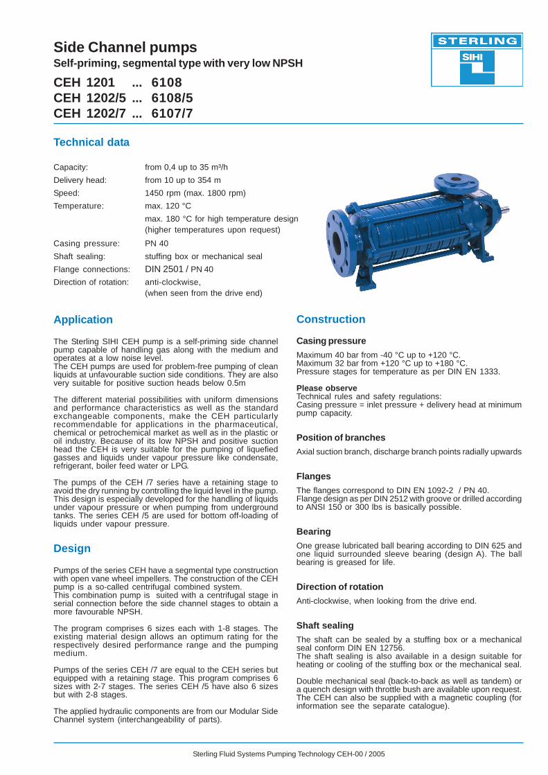
The Sterling SIHI CEH pump is a self-priming side channelpump capable of handling gas along with the medium andoperates at a low noise level.The CEH pumps are used for problem-free pumping of cleanliquids at unfavourable suction side conditions. They are alsovery suitable for positive suction heads below 0.5m
The different material possibilities with uniform dimensionsand performance characteristics as well as the standardexchangeable components, make the CEH particularlyrecommendable for applications in the pharmaceutical,chemical or petrochemical market as well as in the plastic oroil industry. Because of its low NPSH and positive suctionhead the CEH is very suitable for the pumping of liquefiedgasses and liquids under vapour pressure like condensate,refrigerant, boiler feed water or LPG.
The pumps of the CEH /7 series have a retaining stage toavoid the dry running by controlling the liquid level in the pump.This design is especially developed for the handling of liquidsunder vapour pressure or when pumping from undergroundtanks. The series CEH /5 are used for bottom off-loading ofliquids under vapour pressure.
Design
Pumps of the series CEH have a segmental type constructionwith open vane wheel impellers. The construction of the CEHpump is a so-called centrifugal combined system.This combination pump is suited with a centrifugal stage inserial connection before the side channel stages to obtain amore favourable NPSH.
The program comprises 6 sizes each with 1-8 stages. Theexisting material design allows an optimum rating for therespectively desired performance range and the pumpingmedium.
Pumps of the series CEH /7 are equal to the CEH series butequipped with a retaining stage. This program comprises 6sizes with 2-7 stages. The series CEH /5 have also 6 sizesbut with 2-8 stages.
The applied hydraulic components are from our Modular SideChannel system (interchangeability of parts).
Construction
Casing pressure
Maximum 40 bar from -40 °C up to +120 °C.Maximum 32 bar from +120 °C up to +180 °C.Pressure stages for temperature as per DIN EN 1333.
Please observeTechnical rules and safety regulations:Casing pressure = inlet pressure + delivery head at minimumpump capacity.
Position of branches
Axial suction branch, discharge branch points radially upwards
Flanges
The flanges correspond to DIN EN 1092-2 / PN 40.Flange design as per DIN 2512 with groove or drilled accordingto ANSI 150 or 300 lbs is basically possible.
Bearing
One grease lubricated ball bearing according to DIN 625 andone liquid surrounded sleeve bearing (design A). The ballbearing is greased for life.
Direction of rotation
Anti-clockwise, when looking from the drive end.
Shaft sealing
The shaft can be sealed by a stuffing box or a mechanicalseal conform DIN EN 12756.The shaft sealing is also available in a design suitable forheating or cooling of the stuffing box or the mechanical seal.
Double mechanical seal (back-to-back as well as tandem) ora quench design with throttle bush are available upon request.The CEH can also be supplied with a magnetic coupling (forinformation see the separate catalogue).
Technical data
Capacity: from 0,4 up to 35 m³/h
Delivery head: from 10 up to 354 m
Speed: 1450 rpm (max. 1800 rpm)
Temperature: max. 120 °C
max. 180 °C for high temperature design(higher temperatures upon request)
Casing pressure: PN 40
Shaft sealing: stuffing box or mechanical seal
Flange connections: DIN 2501 / PN 40
Direction of rotation: anti-clockwise,(when seen from the drive end)
Side Channel pumpsSelf-priming, segmental type with very low NPSH
CEH 1201 ... 6108CEH 1202/5 ... 6108/5CEH 1202/7 ... 6107/7
Sterling Fluid Systems Pumping Technology CEH-00 / 2005
Sterling Fluid Systems Pumping Technology CEH-00 / 2005 Page 2 / 20
Casing seal
The casing can be sealed with a liquid sealing compoundor soft Teflon.
Drive
By electric motor, type of construction IM B3.For LPG, EExe or Eex d(e) motors are available.
Stainless steel
Cast iron and Ductile iron
* Bearing bush in Carbon Antimony is used only in the high temperature design. This high temperature design is also providedwith cup springs and a cooled stuffing box or cooled mechanical seal.
General comments
Side Channel pumps with the same hydraulic construction aremanufactured in series as:
CEH With magnetic couplingCEB Vertical tank mounted pump, PN 25 with magnetic
couplingCEV Vertical tank mounted pump, PN 25
with mechanical seal (replacement of CVGP)AEH High duty pump, PN 40
Also available with magnetic couplingAKH Medium duty pump, PN 16AOH Low duty pump with oval flanges, PN 10
Technical documents about these pump series will be readilysupplied on request.
Material design CEH
Pos Components Material design4B 4F
2350 Vane wheel impeller G-X 3 CrNiMoCuN 26 6 3 3 PAEK
3500 Bearing housing EN-GJL-250 coated
4410 Mechanical seal casing G-X 6 CrNiMo 18 10
2100 Shaft X 5 CrNiMo 17 12 2
G-X 6 CrNiMo 18 10
1060
1070
1080109011401141
Suction casing
Discharge casing
Intermediate piece
0241 Bearing bush
2310 Impeller G-X5 CrNiMoNb 18 10
Pos Components Material design0A 0B 0F 1A 1B 1F
1060
1070
1080109011401141
Suction casing
Discharge casing
Intermediate piece EN-GJL-250 EN-GJS-400-18-LT
2100 Shaft X 20 Cr 13
EN-GJL-2503500 Bearing housing
EN-GJL-250 EN-GJS-400-18-LT4410
4510
Mechanical seal casing
Stuffing box casing
2350 Vane wheel impeller CuZn40Al2 G-X 3 CrNiMoCuN 26 6 3 3 PAEK PAEKCuZn40Al2 G-X 3 CrNiMoCuN 26 6 3 3
0241 Bearing bush CY 10 C / Carbon Antimony *
2310 Impeller EN-GJL-250
* Bearing bush in Carbon Antimony is used only in the high temperature design. This high temperature design is also providedwith cup springs and a cooled stuffing box or cooled mechanical seal.
CY 10 C / Carbon Antimony *
Sterling Fluid Systems Pumping Technology CEH-00 / 2005 Page 3 / 20
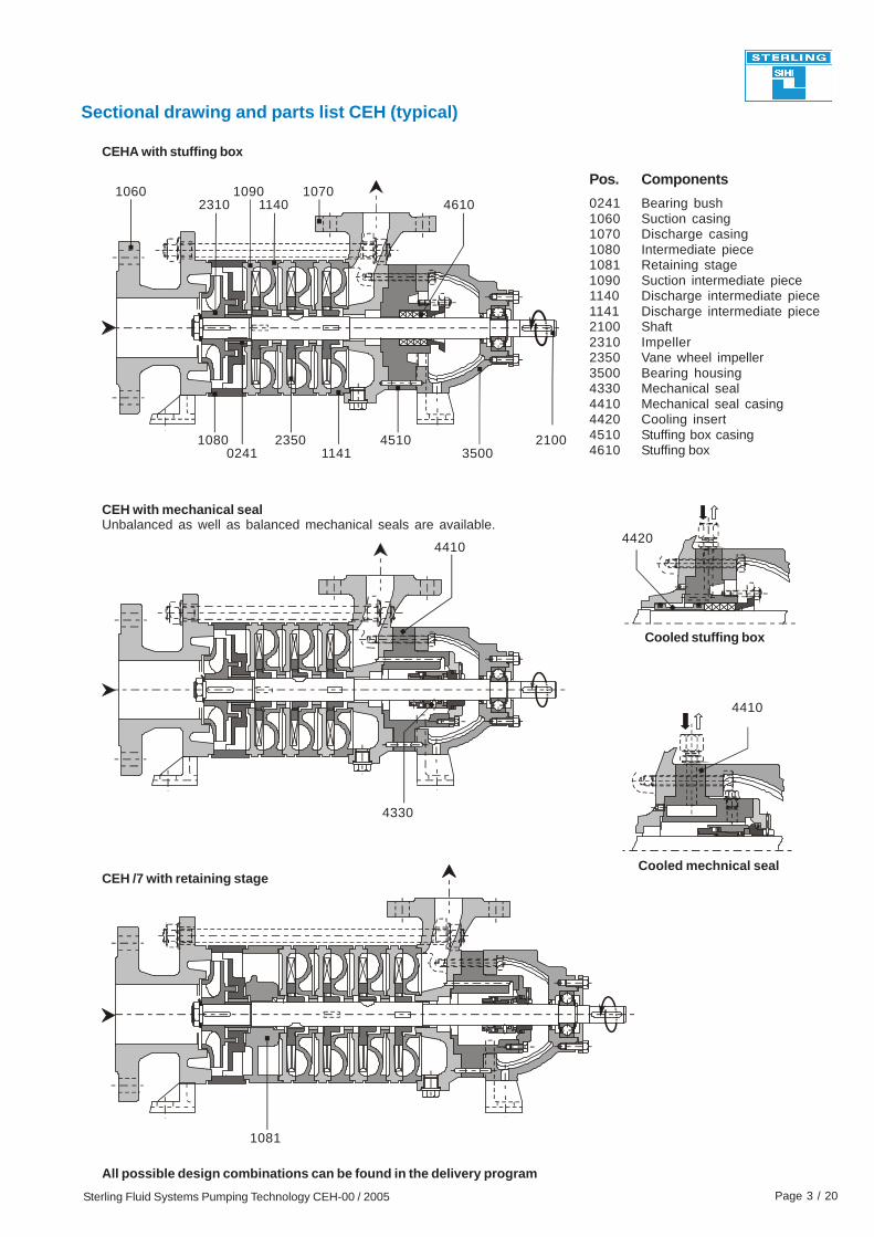
Sectional drawing and parts list CEH (typical)
CEHA with stuffing box
Cooled stuffing box
CEH with mechanical sealUnbalanced as well as balanced mechanical seals are available.
Cooled mechnical sealCEH /7 with retaining stage
1060 109011402310
10800241 1141
451023503500
2100
1070
4410
1081
4330
4610
4410
4420
All possible design combinations can be found in the delivery program
Pos. Components
0241 Bearing bush1060 Suction casing1070 Discharge casing1080 Intermediate piece1081 Retaining stage1090 Suction intermediate piece1140 Discharge intermediate piece1141 Discharge intermediate piece2100 Shaft2310 Impeller2350 Vane wheel impeller3500 Bearing housing4330 Mechanical seal4410 Mechanical seal casing4420 Cooling insert4510 Stuffing box casing4610 Stuffing box
Sterling Fluid Systems Pumping Technology CEH-00 / 2005 Page 4 / 20
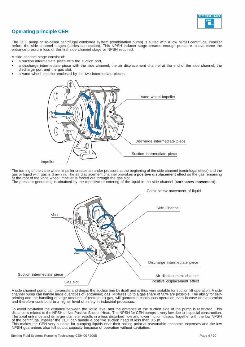
Impeller
Gas slot
The CEH pump or so-called centrifugal combined system (combination pump) is suited with a low NPSH centrifugal impellerbefore the side channel stages (series connection). This NPSH inducer stage creates enough pressure to overcome theentrance pressure loss of the first side channel stage or NPSH required.
A side channel stage consist of:• a suction intermediate piece with the suction port,• a discharge intermediate piece with the side channel, the air displacement channel at the end of the side channel, the
discharge port and the gas slot,• a vane wheel impeller enclosed by the two intermediate pieces.
The turning of the vane wheel impeller creates an under pressure at the beginning of the side channel (centrifugal effect) and thegas or liquid with gas is drawn in. The air displacement channel provokes a positive displacement effect so the gas remainingat the root of the vane wheel impeller is forced out through the gas slot.The pressure generating is obtained by the repetitive re-entering of the liquid in the side channel (corkscrew movement).
A side channel pump can de-aerate and degas the suction line by itself and is thus very suitable for suction lift operation. A sidechannel pump can handle large quantities of (entrained) gas. Mixtures up to a gas share of 50% are possible. The ability for self-priming and the handling of large amounts of (entrained) gas, will guarantee continuous operation even in case of evaporationand therefore contribute to a higher level of safety in industrial processes.
To avoid cavitation the distance between the liquid level and the entrance at the suction side of the pump is restricted. Thisdistance is related to the NPSH or Net Positive Suction Head. The NPSH for CEH pumps is very low due to it special construction.The axial entrance and its larger diameter results in a less disturbed flow and lower friction losses. Together with the low NPSHof the centrifugal impeller the CEH can handle a positive suction head of less than 0.5 m.This makes the CEH very suitable for pumping liquids near their boiling point at reasonable economic expenses and the lowNPSH guarantees also full output capacity because of operation without cavitation.
Vane wheel impeller
Discharge intermediate piece
Suction intermediate piece
Discharge intermediate piece
Side Channel
Corck screw movement of liquid
Air displacement channelPositive displacement effect
Suction intermediate piece
Gas
Operating principle CEH
Sterling Fluid Systems Pumping Technology CEH-00 / 2005 Page 5 / 20
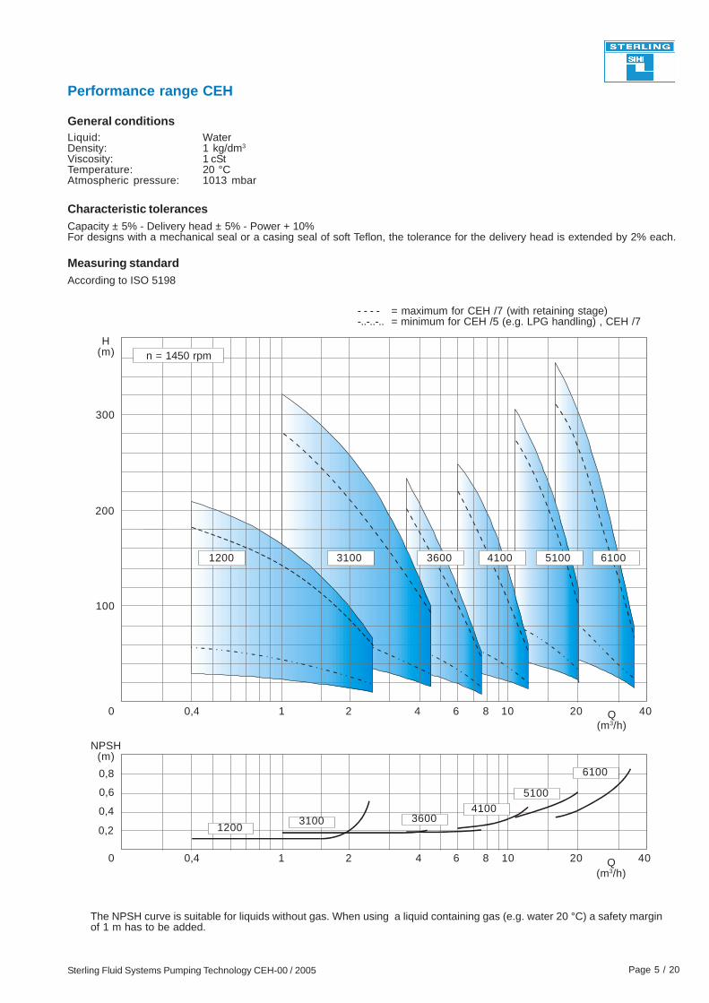
Performance range CEH
The NPSH curve is suitable for liquids without gas. When using a liquid containing gas (e.g. water 20 °C) a safety marginof 1 m has to be added.
General conditions
Characteristic tolerances
Liquid:Density:Viscosity:Temperature:Atmospheric pressure:
Capacity ± 5% - Delivery head ± 5% - Power + 10%For designs with a mechanical seal or a casing seal of soft Teflon, the tolerance for the delivery head is extended by 2% each.
Water1 kg/dm3
1 cSt20 °C1013 mbar
- - - - = maximum for CEH /7 (with retaining stage)-..-..-.. = minimum for CEH /5 (e.g. LPG handling) , CEH /7
Measuring standardAccording to ISO 5198
300
H(m)
0
100
200
0,4 1 2 4 6 8 10 20 40
NPSH(m)
0,8
0,6
0,4
0,2
1200 3100 3600 4100 5100 6100
12003100 3600
41005100
6100
0 0,4 1 2 4 6 8 10 20 40Q(m3/h)
n = 1450 rpm
Q(m3/h)

Sterling Fluid Systems Pumping Technology CEH-00 / 2005 Page 6 / 20
The weight of the pump will be approximately 6% higher when using Stainless steel.
h3
105
100
140e2b2
16,1
5∅14j5
DN40∅18x4
∅110∅150
DN20∅75
∅105
w 1
e1
113
41
m2m1
v
25171
w
a
f1
44
d
∅14x4
H(m)
P(kW)
NPSH3)
(m)
200
100
3
0
2
1
0
0,40,2
01 2 3
1450 rpm
0,6
Q(m3/h)
4
100
c
176 10
35 13
G¼
Dimension chart, Pump set drawing and Performance curves
CEH 1200 and CEHA 1200/5
0
1208120712061205120412031202
12011)
120812071206120512041203120212011)
General: Values are valid for water ρ = 1 kg/dm3 and ν = 1 cSt.
Capacity ± 5% - Delivery head ± 5% - Power + 10%.For designs with a mechanical seal or casing seal of soft Teflon,the tolerance for the delivery head is extended by 2% each.
Design tolerances:
* Dimensions depend upon the motor brand.1) Not for design CEH /5.2) For EExe II T3 motors.3) A safety margin of 1 m has to be added when using a liquid containing gas.
Pum p Base s ize kW kW2) s ize plate B BDS2) pum p s et a b2 c d e 1 e 2 v f1 h3 m 1 m 2 w * w 1
0.37 71 P007 39 317 350 285 110 135 609 5700.55 80 P008 45 297 400 265 120 140 643 6400.55 0.55 80 470.75 0.75 80 441.1 1 90S P241 56 330 25 19 480 290 125 165 735 730
0.75 0.75 80 P210 52 300 420 260 115 711 6501.1 1 90S 581.5 1.35 90L 621.1 1 90S 601.5 1.35 90L 642.2 2 100L P272 80 88 75 360 540 320 140 844 8201.1 1 90S 661.5 1.35 90L 702.2 2 100L 80 88 77 8781.5 1.35 90L P272 68 76 72 360 19 540 320 140 165 871 8202.2 2 100L 84 9123 2.5 100L 85 912
1.5 1.35 90L 68 76 74 9052.2 2 100L 863 2.5 100L 87
2.2 2 100L 883 2.5 100L 89
320540
P015 32560015 920150-9160946
480330 25
331
330
360
1925
820165-9140 837
408442
374
374
340
263
19
238272
272306
1925
480
28
30
60015361365 25
361399 25
20
22
24
26
88
76
76
68
1206
1207
1202
1203
150-916032 361433 3256001525 920980442476
920150160325-9 408
730803125290 -9 165 306340
730769125290-9 165
640677140120 -9
204238-920 15
26540015229 297 20
195
297
88
88
80
80
801208
P008
P241
P241
P015
P015
1204
1205
M otor Coupling
68
68
76
68 76
P272
Weight
1201 181)681)
Sterling Fluid Systems Pumping Technology CEH-00 / 2005 Page 7 / 20
Dimension chart, Pump set drawing and Performance curves
h3
135
132
170e2
21,5
6
∅19j5
DN65
∅18x8
∅145∅185
DN32∅100
e1
134
42
m2m1
v
40201a
f1
50
d
∅18x4
w
∅140
The weight of the pump will be approximately 6% higher when using Stainless steel.
H(m)
P(kW)
NPSH3)
(m)
300
200
0
6
4
2
01 2 3 4
100
0
0,2
1450 rpm
1
3
5
Q(m3/h)
w 1
112214 12
c
35 13
G¼
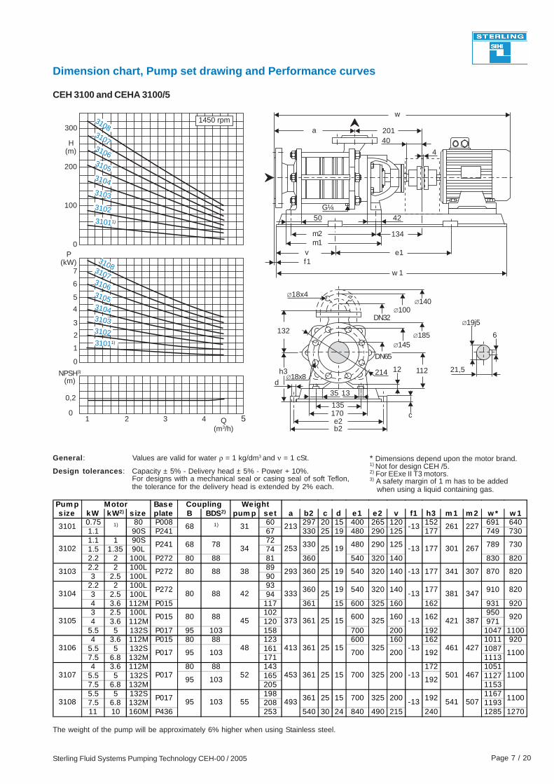
CEH 3100 and CEHA 3100/5
7
5b2
310831073106310531043103
3102
31011)
310831073106310531043103310231011)
General: Values are valid for water ρ = 1 kg/dm3 and ν = 1 cSt.
Capacity ± 5% - Delivery head ± 5% - Power + 10%.For designs with a mechanical seal or casing seal of soft Teflon,the tolerance for the delivery head is extended by 2% each.
Design tolerances:
4
* Dimensions depend upon the motor brand.1) Not for design CEH /5.2) For EExe II T3 motors.3) A safety margin of 1 m has to be added when using a liquid containing gas.
Pum p Base s ize kW kW2) s ize plate B BDS2) pum p set a b2 c d e1 e2 v f1 h3 m 1 m 2 w * w 1
0.75 80 P008 60 297 20 15 400 265 120 152 691 6401.1 90S P241 67 330 25 19 480 290 125 177 749 7301.1 1 90S 721.5 1.35 90L 742.2 2 100L P272 80 88 81 360 540 320 140 830 8202.2 2 100L 893 2.5 100L 90
2.2 2 100L 933 2.5 100L 944 3.6 112M P015 117 361 15 600 325 160 162 931 9203 2.5 100L 102 9504 3.6 112M 120 971
5.5 5 132S P017 95 103 158 700 200 192 1047 11004 3.6 112M P015 80 88 123 600 160 162 1011 920
5.5 5 132S 161 10877.5 6.8 132M 171 11134 3.6 112M 80 88 143 172 1051
5.5 5 132S 165 11277.5 6.8 132M 205 11535.5 5 132S 198 11677.5 6.8 132M 208 119311 10 160M P436 253 540 30 24 840 490 215 240 1285 1270
P01795
45352
88
88 45
103
15
70015
1)
361
333
373
413
42
38
1100-13200325 467501192
360 25
25361
25
60015
32054019
177-132525334
5401925360
4801933078
1)
3105
3106
3107
3102
3104
1100192200700-1332548
387
461
-13 421
427
32525361 160 920162
820910177140 347381-13
820870307341177-13140320
730789125290 267301
227261-13213
P272
P015
P017
31
29388
80
68
80
68
80
3101
3103
P241
P272
3108 95 55 15493 541 507
Motor Coupling Weight
P017 103
10395
192200325 -1325361 1100700
Sterling Fluid Systems Pumping Technology CEH-00 / 2005 Page 8 / 20
h3
135
132
170e2b2
21,5
6
∅19j5
DN65
∅18x8
∅145∅185
DN32∅100
w 1
e1
134
42
m2m1
v
40201a
f1
50
d
∅18x4∅140
w
The weight of the pump will be approximately 6% higher when using Stainless steel.
H(m)
P(kW)
NPSH3)
(m)
200
0
4
2
3 4 5 76
100
5
0,5
0,2
3
1
8
1450 rpm
6
Q(m3/h)
c
112214 12
35 13
G¼
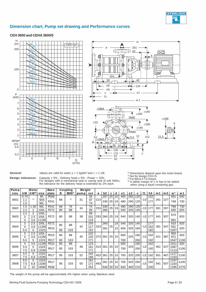
Dimension chart, Pump set drawing and Performance curves
CEH 3600 and CEHA 3600/5
7
3608360736063605360436033602
36011)
360836073606360536043603
3602
36011)
General: Values are valid for water ρ = 1 kg/dm3 and ν = 1 cSt.
Capacity ± 5% - Delivery head ± 5% - Power + 10%.For designs with a mechanical seal or casing seal of soft Teflon,the tolerance for the delivery head is extended by 2% each.
Design tolerances:
4
* Dimensions depend upon the motor brand.1) Not for design CEH /5.2) For EExe II T3 motors.3) A safety margin of 1 m has to be added when using a liquid containing gas.
Pum p Base s ize kW kW2) s ize plate B BDS2) pum p set a b2 c d e1 e2 v f1 h3 m 1 m 2 w * w 1
0.75 80 P008 55 297 20 15 400 265 120 152 691 6401.1 90S 671.5 90L 741.5 1.35 90L P241 68 76 74 330 480 290 125 789 7302.2 2 100L P272 80 88 89 360 540 320 140 830 8202.2 2 100L 893 2.5 100L 1014 3.6 112M 119 8913 2.5 100L P272 105 360 19 540 320 140 177 910 8204 3.6 112M 117 162 931
5.5 5 132S 95 103 152 182 10073 2.5 100L 102 9504 3.6 112M 120 971
5.5 5 132S P017 95 103 171 700 200 192 1047 11004 3.6 112M P015 80 88 123 600 160 162 1011 920
5.5 5 132S 161 10877.5 6.8 132M 171 11135.5 5 132S 165 11277.5 6.8 132M 168 11535.5 5 132S 161 11677.5 6.8 132M 171 119311 10 160M P436 254 540 30 24 840 490 215 240 1285 1270
68
80
95
1)3601
3603
3604
3602
3605
3606
3608
3607
31
38
42
45
48
55
80
95 52
373
413
493
453
347
213
293
333
253
261
-13
361
361
361
25
25
20025
Motor Coupling Weight
P272
P015
P017 95 103
88
820177
541 507
325
600
325700
325
700
15
325
700
320 140
-13
-13
730749177125290480330
360
177
5401925
19 -13
1925
870
26730125
341 307
227
P01580
361 600152588
P241
34
920
920162160 -13 387421
160-13 381
200 192
15
151100
1100192-13 467501
-13 461 427
P017 103
110019220032525361P017 15
1)
88
103
Sterling Fluid Systems Pumping Technology CEH-00 / 2005 Page 9 / 20
h3
155
140
195e2b2
26,9
8
∅24j5
DN80
∅18x8
∅160∅200
DN40∅110
w 1
e1
140
43
m2m1
v
45195a
f1
52
d
∅18x4∅150
w
The weight of the pump will be approximately 6% higher when using Stainless steel.
H(m)
P(kW)
NPSH3)
(m)
200
0
12
10
8
6 7 8 109
100
6
0,5
0
4
2
11 12
1450 rpm
4107
13Q(m3/h)
238 13215
c
40 13
G¼
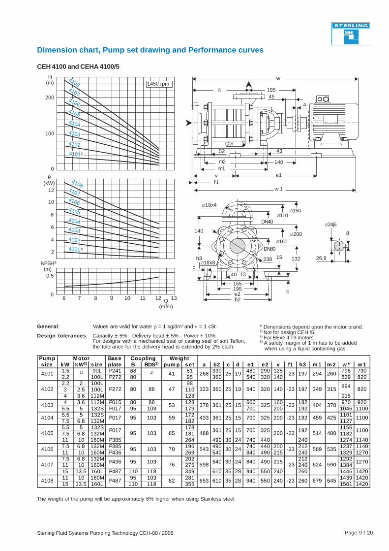
Dimension chart, Pump set drawing and Performance curves
CEH 4100 and CEHA 4100/5
4108410741064105
4104
4103
4102
41011)
4108
4106410541044103
4102
41011)
General: Values are valid for water ρ = 1 kg/dm3 and ν = 1 cSt.
Capacity ± 5% - Delivery head ± 5% - Power + 10%.For designs with a mechanical seal or casing seal of soft Teflon,the tolerance for the delivery head is extended by 2% each.
Design tolerances:
4
* Dimensions depend upon the motor brand.1) Not for design CEH /5.2) For EExe II T3 motors.3) A safety margin of 1 m has to be added when using a liquid containing gas.
Pum p Base s ize kW kW2) s ize plate B BDS2) pum p set a b2 c d e1 e2 v f1 h3 m 1 m 2 w * w 1
1.5 90L P241 68 81 330 480 290 125 798 7302.2 100L P272 80 95 360 540 320 140 839 8202.2 2 100L 983 2.5 100L 1104 3.6 112M 128 9154 3.6 112M P015 80 88 128 600 160 182 970 920
5.5 5 132S P017 95 103 179 700 200 192 1046 11005.5 5 132S 172 11017.5 6.8 132M 182 11275.5 5 132S 178 11567.5 6.8 132M 181 118211 10 160M P385 264 490 30 24 740 440 240 1274 11407.5 6.8 132M P385 196 490 740 440 200 212 1237 114011 10 160M P436 269 540 840 490 215 240 1329 12707.5 6.8 132M 202 212 129211 10 160M 275 240 138415 13.5 160L P487 110 118 349 610 35 28 940 550 240 260 1446 142011 10 160M 95 103 281 1439 142015 13.5 160L 110 118 355 1501 1420
95 65
1)1)
4102
4105
4107
80
41
47
Weight
323
598
-2325
15
15
24
24
140
200
32570025361
361
360 19
Motor Coupling
P272 820197 894349 315540 320
19 197-2325268
370404
260294
-2332525361 1537853
P017 95 59 433103 1100192-23200 425459
P017 1100192325700 -23 514 480488 25
543 535569-2330
1270215490840 -23 624 5903054095
88
103
103
103
4108 P487 645679260-232405509402835610653
4104
4103
4101
82
4106 95 70
76P436
Sterling Fluid Systems Pumping Technology CEH-00 / 2005 Page 10 / 20
h3
170
165
215e2
30,9
8
∅24j5
DN100
∅22x8
∅190∅235
DN50∅125
w 1
e1
159
66
m2
v
50237a
f1
60
d
∅18x4∅165
w
m1
The weight of the pump will be approximately 6% higher when using Stainless steel.
H(m)
P(kW)
NPSH3)
(m)
300
30
0
20
12 14
200
10
0
0,5
16
1450 rpm
100
18 20b2
Q(m3/h)
18
c
276 160
1545
G¼
Dimension chart, Pump set drawing and Performance curves
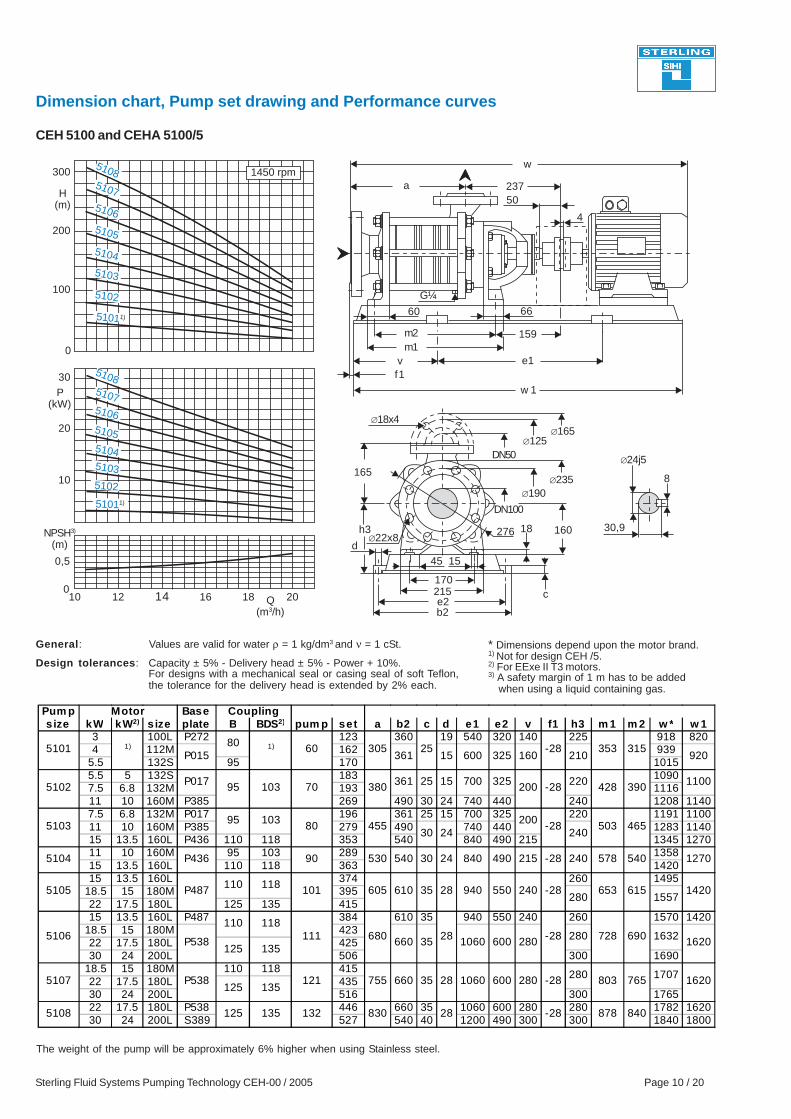
CEH 5100 and CEHA 5100/5
10
51085107
5106
5105
5104
5103
5102
51011)
510851075106510551045103
5102
51011)
General: Values are valid for water ρ = 1 kg/dm3 and ν = 1 cSt.
Capacity ± 5% - Delivery head ± 5% - Power + 10%.For designs with a mechanical seal or casing seal of soft Teflon,the tolerance for the delivery head is extended by 2% each.
Design tolerances:
4
* Dimensions depend upon the motor brand.1) Not for design CEH /5.2) For EExe II T3 motors.3) A safety margin of 1 m has to be added when using a liquid containing gas.
Pum p Base s ize kW kW2) s ize plate B BDS2) pum p set a b2 c d e1 e2 v f1 h3 m 1 m 2 w * w 1
3 100L P272 123 360 19 540 320 140 225 918 8204 112M 162 939
5.5 132S 95 170 10155.5 5 132S 183 10907.5 6.8 132M 193 111611 10 160M P385 269 490 30 24 740 440 240 1208 11407.5 6.8 132M P017 196 361 25 15 700 325 220 1191 110011 10 160M P385 279 490 740 440 1283 114015 13.5 160L P436 110 118 353 540 840 490 215 1345 127011 10 160M 95 103 289 135815 13.5 160L 110 118 363 142015 13.5 160L 374 260 1495
18.5 15 180M 39522 17.5 180L 125 135 41515 13.5 160L P487 384 610 35 940 550 240 260 1570 1420
18.5 15 180M 42322 17.5 180L 42530 24 200L 506 300 1690
18.5 15 180M 110 118 41522 17.5 180L 43530 24 200L 516 300 176522 17.5 180L P538 446 660 35 1060 600 280 280 1782 162030 24 200L S389 527 540 40 1200 490 300 300 1840 1800
1)1)
28
28
5104
5108
5103
5105
5107
5106
P015
P017
P436
5101
5102
125 135
125 135
125 135
121
101
80
111
92021016032560015361
24
15
-28
1100220325700 390428
530 -28215490840
1632280
24 540578240
-282405501557
840878-28
280
728-28 690
830
-2825305 315353
455
25361
465503240
20030
-28200
1270
610 1420615653
30540
605
1620280600106035660
9402835
1620765803-28 280 1707755 35 280600106028
680
380
P487
P538
95
90
P538
132
60
95
80
Motor
103 70
103
110 118
110 118
Coupling
660
Sterling Fluid Systems Pumping Technology CEH-00 / 2005 Page 11 / 20
h3
195
180
245e2
35,3
10
∅32j5
DN100
∅22x8
∅190∅235
DN65∅145
w 1
e1
172
63
m2m1
v
65262a
f1
64
d
∅18x4 ∅185
w
The weight of the pump will be approximately 6% higher when using Stainless steel.
H(m)
P(kW)
NPSH3)
(m)
300
0
50
20 25 30
200
40
0,5
30
1450 rpm
100
20
10
0
15 35
b2Q
(m3/h)
50 15
300 20
c
180
G3/8
Dimension chart, Pump set drawing and Performance curves
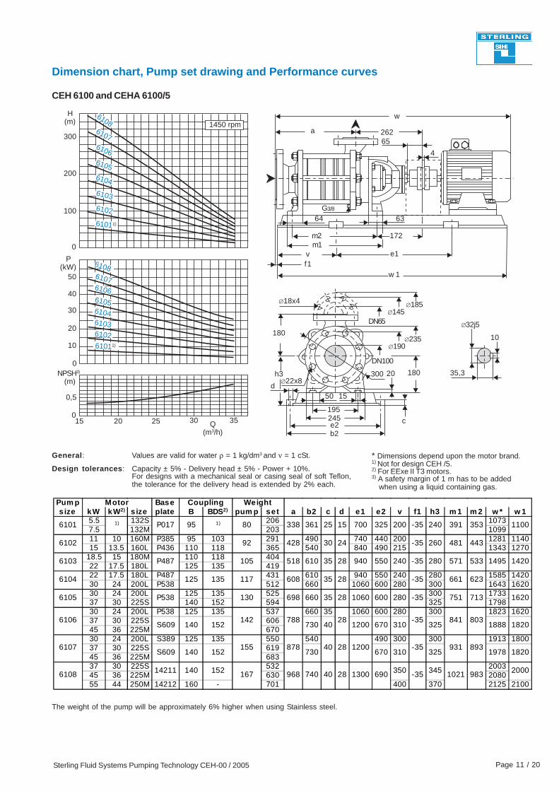
CEH 6100 and CEHA 6100/5
0
61086107610661056104
6103
6102
61011)
610861076106610561046103610261011)
General: Values are valid for water ρ = 1 kg/dm3 and ν = 1 cSt.
Capacity ± 5% - Delivery head ± 5% - Power + 10%.For designs with a mechanical seal or casing seal of soft Teflon,the tolerance for the delivery head is extended by 2% each.
Design tolerances:
4
* Dimensions depend upon the motor brand.1) Not for design CEH /5.2) For EExe II T3 motors.3) A safety margin of 1 m has to be added when using a liquid containing gas.
Pum p Base s ize kW kW2) s ize plate B BDS2) pum p set a b2 c d e1 e2 v f1 h3 m 1 m 2 w * w 1
5.5 132S 206 10737.5 132M 203 109911 10 160M P385 95 103 291 490 740 440 200 1281 114015 13.5 160L P436 110 118 365 540 840 490 215 1343 1270
18.5 15 180M 110 118 40422 17.5 180L 125 135 41922 17.5 180L P487 431 610 940 550 240 280 1585 142030 24 200L P538 512 660 1060 600 280 300 1643 162030 24 200L 125 135 525 300 173337 30 225S 140 152 594 325 179830 24 200L P538 125 135 537 660 35 1060 600 280 300 1823 162037 30 225S 60645 36 225M 67030 24 200L S389 125 135 550 540 490 300 300 1913 180037 30 225S 61945 36 225M 68337 30 225S 532 200345 36 225M 630 208055 44 250M 14212 160 - 701 400 370 2125 2100
350 345 200014211 40 28 1300 690 1021 983740
1)
28
24
6101
6102
6103
6104
6105
P017
P487
P538
125 135
S609
S609 140
140
95 1) 80
92
105
117
130
1100353391240-352003257001525361338
443481260-3530428
610 14201495533571
1820
518
623661-3535608
9402835
106028 1620713751-35280600
1888325310
18201978325310893931-35
6106
6107 155
142152
152878 40
788730
730
35660698
40803841
670
6701200
280-35240550
Motor Coupling Weight
6108 167140 152 -35968
28
28
1200
-35
Sterling Fluid Systems Pumping Technology CEH-00 / 2005 Page 12 / 20
Dimension chart, Pump set drawing and Performance curves
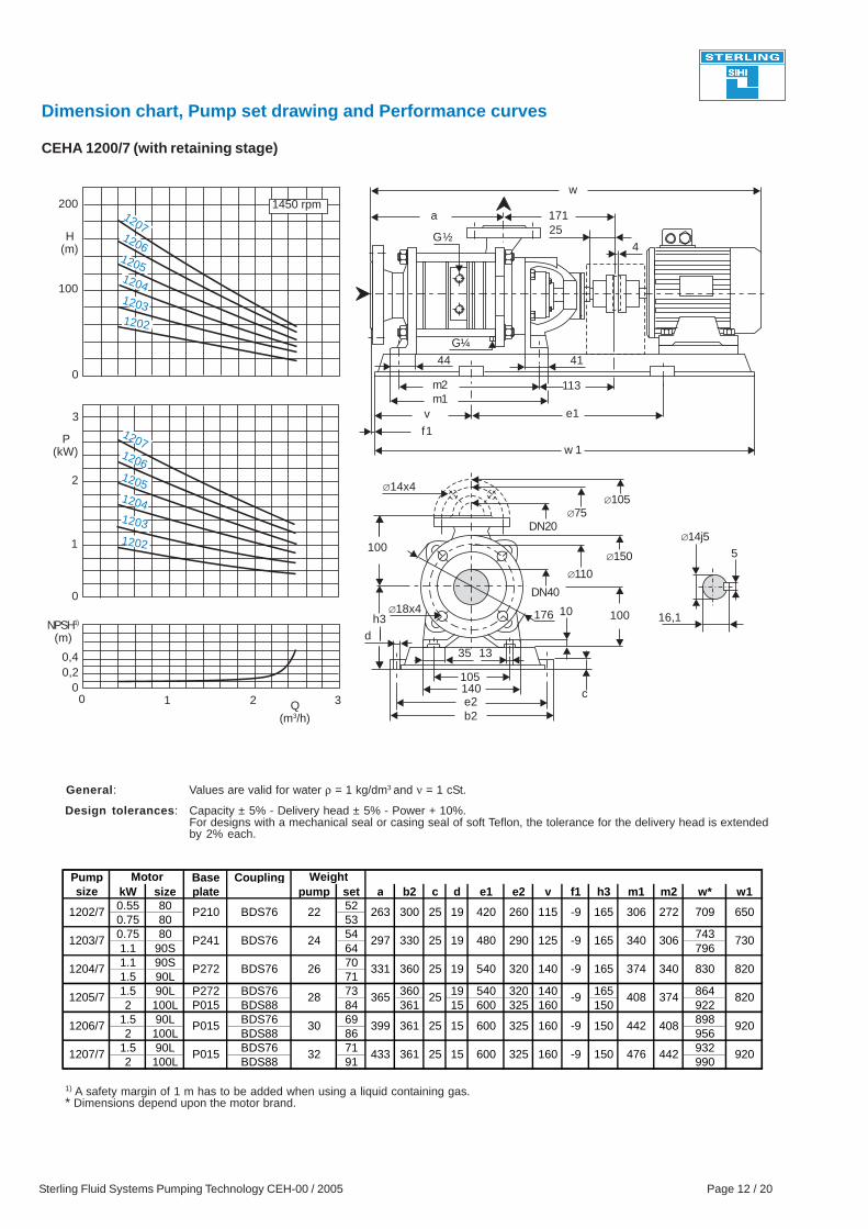
General: Values are valid for water ρ = 1 kg/dm3 and ν = 1 cSt.
Capacity ± 5% - Delivery head ± 5% - Power + 10%.For designs with a mechanical seal or casing seal of soft Teflon, the tolerance for the delivery head is extendedby 2% each.
Design tolerances:
h3
105
100
140e2b2
16,1
5∅14j5
DN40∅18x4
∅110
∅150
DN20∅75
∅105
w 1
e1
113
41
m2m1
v
25171a
f1
44
∅14x4
w
1) A safety margin of 1 m has to be added when using a liquid containing gas.* Dimensions depend upon the motor brand.
d
H(m)
P(kW)
200
100
3
0
2
1
0
0,40,2
01 2
1450 rpm
3Q(m3/h)
c
35 13
176 10 100
G½
G¼
CEHA 1200/7 (with retaining stage)
0
NPSH1)
(m)
120712061205120412031202
12071206120512041203
1202
4
Pump Base Couplingsize kW size plate pump set a b2 c d e1 e2 v f1 h3 m1 m2 w* w1
0.55 80 520.75 80 530.75 80 54 7431.1 90S 64 7961.1 90S 701.5 90L 711.5 90L P272 BDS76 73 360 19 540 320 140 165 8642 100L P015 BDS88 84 361 15 600 325 160 150 922
1.5 90L BDS76 69 8982 100L BDS88 86 956
1.5 90L BDS76 71 9322 100L BDS88 91 990
1525361433 -9160325600 920442476150
1525361399 -9160325600 920408442150
25365
320540
820374408-9
25330
360331
297
25 820830340374165-914019
263
730306340165-912529048019
4201925300 165-9115260 650709272306
BDS76 26
28
30
32
P015
P015
1204/7
1205/7
1206/7
1207/7
1202/7
1203/7
P210
P241
Motor Weight
22
24
BDS76
BDS76
P272
Sterling Fluid Systems Pumping Technology CEH-00 / 2005 Page 13 / 20
h3
135
132
170e2b2
21,5
6
∅19j5
DN65
∅18x8
∅145
∅185
DN32∅100
w 1
e1
134
42
m2m1
v
40
201a
f1
50
d
∅18x4∅140
w
H(m)
P(kW)
300
200
0
6
4
2
01 2 3 4
100
0
0,2
1450 rpm
1
3
5
Q(m3/h)
35 13
21412 112
c
G½
G¼
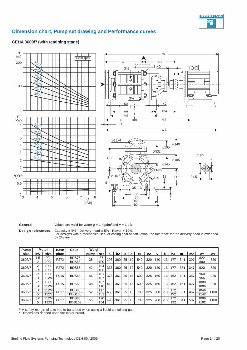
Dimension chart, Pump set drawing and Performance curves
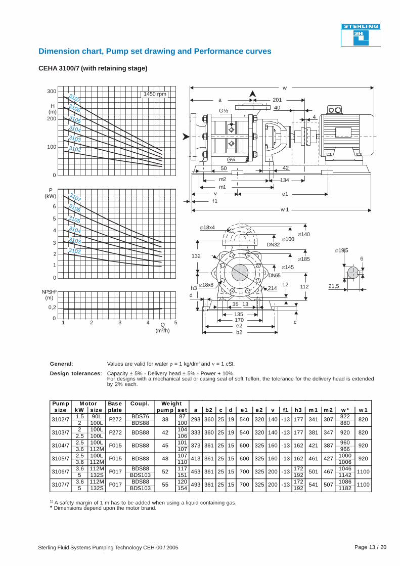
CEHA 3100/7 (with retaining stage)
5
NPSH1)
(m)
31073106310531043103
3102
31073106
31053104
3103
3102
General: Values are valid for water ρ = 1 kg/dm3 and ν = 1 cSt.
Capacity ± 5% - Delivery head ± 5% - Power + 10%.For designs with a mechanical seal or casing seal of soft Teflon, the tolerance for the delivery head is extendedby 2% each.
Design tolerances:
4
1) A safety margin of 1 m has to be added when using a liquid containing gas.* Dimensions depend upon the motor brand.
Pum p Base Coupl.s ize kW size plate pum p set a b2 c d e1 e2 v f1 h3 m 1 m 2 w * w 1
1.5 90L BDS76 87 8222 100L BDS88 100 8802 100L 104
2.5 100L 1062.5 100L 101 9603.6 112M 107 9662.5 100L 107 10003.6 112M 110 10063.6 112M BDS88 117 172 10465 132S BDS103 151 192 1142
3.6 112M BDS88 120 172 10865 132S BDS103 154 192 1182
3102/7
3103/7
3104/7
3105/7
3106/7
3107/7
P272
P272
P015
P015
P017
42
45
48
BDS88
820307341177-131403205401925360293
820920347381177-131403205401925360333
920387421162-1316032560025 15361373
920427461162-131603256001525361413
1100467501-132003257001525361453
1100507541-132003257001525361493
M otor Weight
52
55P017
BDS88
BDS88
38
Sterling Fluid Systems Pumping Technology CEH-00 / 2005 Page 14 / 20
h3
135
132
e2
21,5
6∅19j5
DN65
∅18x8
∅145∅185
DN32∅100
w 1
e1
134
42
m2m1
v
40201a
f1
50
d
∅18x4∅140
b2
170
wH(m)
P(kW)
200
0
5
3
3 4 5 76
100
6
0,5
0
4
2
1450 rpm
7
8Q(m3/h)
35
c
13
214 12 112
G½
G¼
Dimension chart, Pump set drawing and Performance curves
CEHA 3600/7 (with retaining stage)
1
NPSH1)
(m)
360736063605360436033602
3607360636053604
3603
3602
General: Values are valid for water ρ = 1 kg/dm3 and ν = 1 cSt.
Capacity ± 5% - Delivery head ± 5% - Power + 10%.For designs with a mechanical seal or casing seal of soft Teflon, the tolerance for the delivery head is extendedby 2% each.
Design tolerances:
4
1) A safety margin of 1 m has to be added when using a liquid containing gas.* Dimensions depend upon the motor brand.
Pump Base Coupl.size kW size plate pump set a b2 c d e1 e2 v f1 h3 m1 m2 w* w1
1.5 90L BDS76 87 8222 100L BDS88 100 8802 100L 104
2.5 100L 1062.5 100L 101 9603.6 112M 107 9662.5 100L 107 10003.6 112M 110 10063.6 112M BDS88 117 172 10465 132S BDS103 151 192 1142
3.6 112M BDS88 120 172 10865 132S BDS103 154 192 1182
Motor Weight
25361493 15
25361453
1100507541-13200325700
20032570015 1100467501-13
1525361413 -13160325600 920427461162
1525361373 -13160325600 920387421162
1925360333
293
820920347381177-13140320540
54025 19360 820307341177-13140320
BDS88
BDS88
BDS88 45
48
52
55
38
42
P015
P017
P017
P272
P015
P272
3604/7
3605/7
3606/7
3607/7
3602/7
3603/7
Sterling Fluid Systems Pumping Technology CEH-00 / 2005 Page 15 / 20
h3
155
140
195e2b2
26,9
8
∅24j5
DN80
∅18x8
∅160∅200
DN40∅110
w 1
e1
140
43
m2m1
v
45
195a
f1
52
d
∅18x4∅150
wH(m)
P
200
0
10
8
6 7 8 109
100
6
0,5
0
4
2
11 12
1450 rpm
13Q(m3/h)
238
c
132
40 13
15
G½
G¼
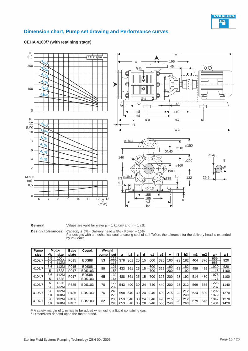
Dimension chart, Pump set drawing and Performance curves
CEHA 4100/7 (with retaining stage)
NPSH1)
(m)
410741064105
41044103
4102
(kW)41074106
4105
4104
4103
4102
General: Values are valid for water ρ = 1 kg/dm3 and ν = 1 cSt.
Capacity ± 5% - Delivery head ± 5% - Power + 10%.For designs with a mechanical seal or casing seal of soft Teflon, the tolerance for the delivery head is extendedby 2% each.
Design tolerances:
12
4
1) A safety margin of 1 m has to be added when using a liquid containing gas.* Dimensions depend upon the motor brand.
Pump Base Coupl.size kW size plate pump set a b2 c d e1 e2 v f1 h3 m1 m2 w* w1
2.5 100L 112 9593.6 112M 115 9653.6 112M P015 BDS88 121 600 160 182 1020 9205 132S P017 BDS103 158 700 200 192 1116 1100
3.6 112M BDS88 130 10755 132S BDS103 164 11715 132S 172 1226
6.8 132M 232 12376.8 132M 248 212 129210 160M 278 240 13796.8 132M P436 230 653 540 30 24 840 490 215 212 1347 127010 160M P487 296 653 610 35 28 940 550 240 260 1434 1420
15
Motor Weight
82BDS103
BDS103
53
59
645679-23
P436 BDS103 76 2430540598
54370P385
1270590624-23215490840
7402430490
48865P017
1140535569212-23200440
7001525361
25361433
1100480514192-23200325
425459-23325
1525361378 -23160325600 920370404182BDS88P015
4106/7
4107/7
4102/7
4103/7
4104/7
4105/7
Sterling Fluid Systems Pumping Technology CEH-00 / 2005 Page 16 / 20
h3
170
165
215e2b2
30,9
8∅24j5
DN100
∅22x8
∅190∅235
DN50∅125
w 1
e1
159
66
m2m1
v
50
237a
f1
60
d
∅18x4∅165
w
H(m)
P(kW)
300
30
0
20
12 14
200
10
16
1450 rpm
100
18 2010Q
(m3/h)
45
c
15
276 16018
G½
G¼
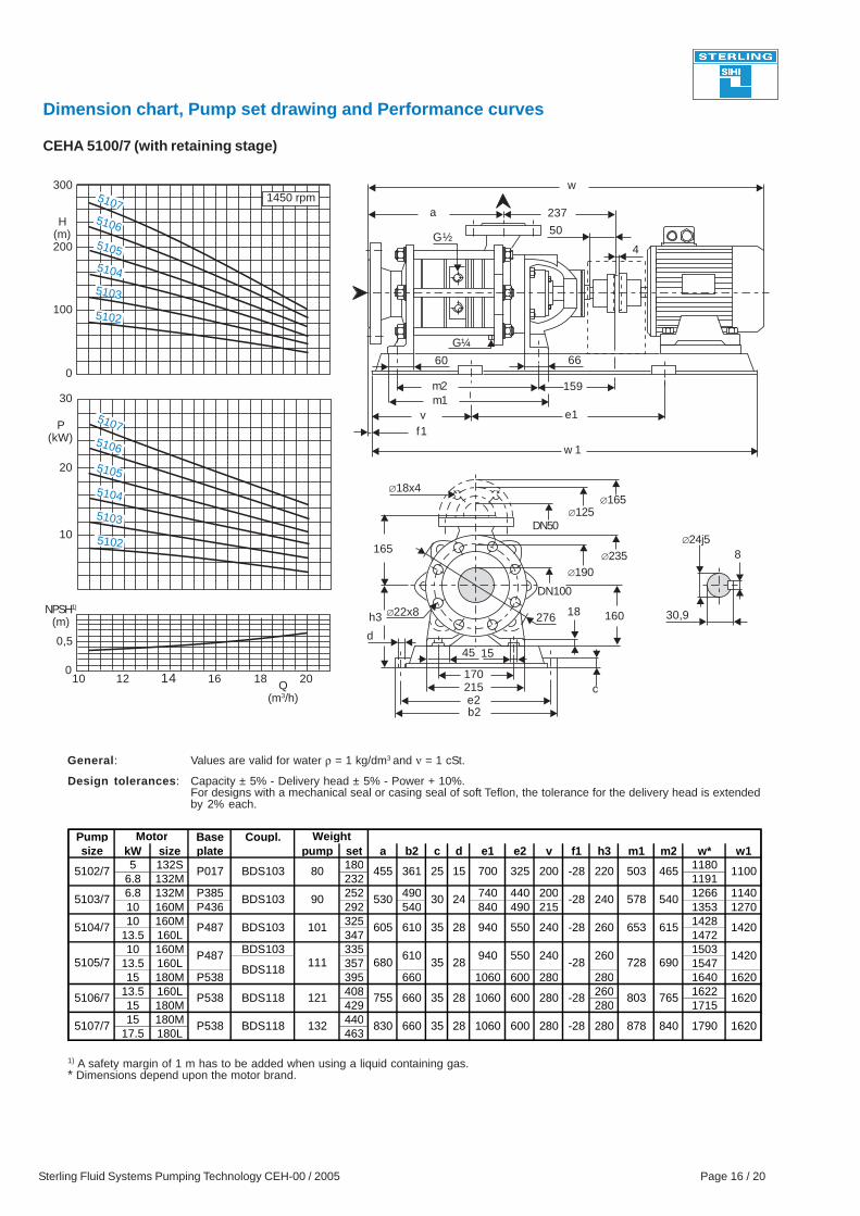
Dimension chart, Pump set drawing and Performance curves
CEHA 5100/7 (with retaining stage)
0
0,5
NPSH1)
(m)
51075106
5105
5104
5103
5102
51075106
5105
5104
5103
5102
General: Values are valid for water ρ = 1 kg/dm3 and ν = 1 cSt.
Capacity ± 5% - Delivery head ± 5% - Power + 10%.For designs with a mechanical seal or casing seal of soft Teflon, the tolerance for the delivery head is extendedby 2% each.
Design tolerances:
4
1) A safety margin of 1 m has to be added when using a liquid containing gas.* Dimensions depend upon the motor brand.
Pump Base Coupl.size kW size plate pump set a b2 c d e1 e2 v f1 h3 m1 m2 w* w1
5 132S 180 11806.8 132M 232 11916.8 132M P385 252 490 740 440 200 1266 114010 160M P436 292 540 840 490 215 1353 127010 160M 325 1428
13.5 160L 347 147210 160M BDS103 335 1503
13.5 160L 357 154715 180M P538 395 660 1060 600 280 280 1640 1620
13.5 160L 408 260 162215 180M 429 280 171515 180M 440
17.5 180L 463
690728
24
28P487
BDS118111
BDS118
830
Motor Weight
1420610 260-2835680
240940 550
132BDS118P538 10602835660
P538
16201790840878280-28280600
35660755121
BDS103 610605101P487
1620765803-28280600106028
35
BDS103
1420615653260-2824055094028
80BDS103P017
540578240-283053090
1525361455 1100465503220-28200325700
5104/7
5106/7
5107/7
5105/7
5102/7
5103/7
Sterling Fluid Systems Pumping Technology CEH-00 / 2005 Page 17 / 20
w
h3
195
180
245e2
35,3
10
∅32j5
DN100
∅22x8
∅190∅235
DN65∅145
w 1
e1
172
63
m2m1
v
65
262a
f1
64
d
∅18x4∅185
b2
H(m)
P(kW)
300
0
50
20 25 30
200
40
0,5
0
30
1450 rpm
100
20
10
0
15 35Q(m3/h)
15
c
50
300 18020
G½
G3/8
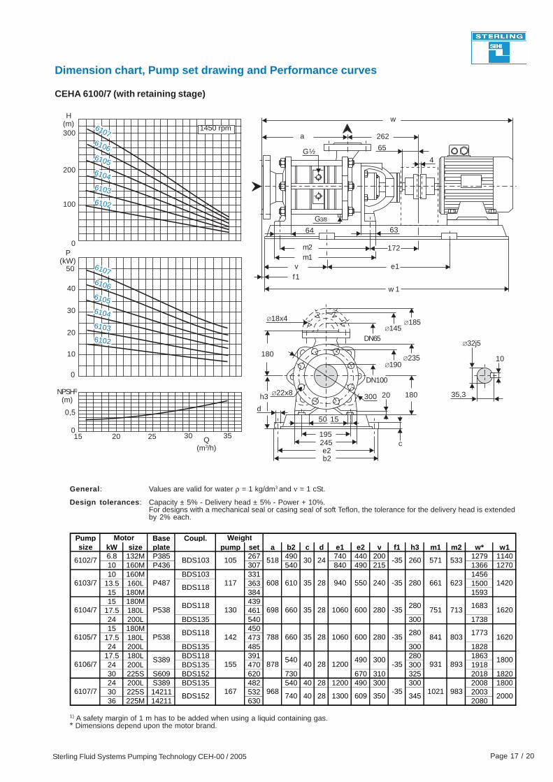
Dimension chart, Pump set drawing and Performance curves
CEHA 6100/7 (with retaining stage)
NPSH1)
(m)
6107610661056104
6103
610761066105
6104
6103
6102
General: Values are valid for water ρ = 1 kg/dm3 and ν = 1 cSt.
Capacity ± 5% - Delivery head ± 5% - Power + 10%.For designs with a mechanical seal or casing seal of soft Teflon, the tolerance for the delivery head is extendedby 2% each.
Design tolerances:
6102
1) A safety margin of 1 m has to be added when using a liquid containing gas.* Dimensions depend upon the motor brand.
4
Pump Base Coupl.size kW size plate pump set a b2 c d e1 e2 v f1 h3 m1 m2 w* w1
6.8 132M P385 267 490 740 440 200 1279 114010 160M P436 307 540 840 490 215 1366 127010 160M BDS103 331 1456
13.5 160L 363 150015 180M 384 159315 180M 439
17.5 180L 46124 200L BDS135 540 300 173815 180M 450
17.5 180L 47324 200L BDS135 485 300 1828
17.5 180L BDS118 391 280 186324 200L BDS135 470 300 191830 225S S609 BDS152 620 730 670 310 325 2018 182024 200L S389 BDS135 482 540 40 28 1200 490 300 300 2008 180030 225S 14211 532 200336 225M 14211 630 2080
24
28
28
28
28
490 300
600
Motor Weight
280
661 623
751 713
550
600
1800
1773841 803
931 893S389
BDS118
BDS118
540878
1420
1620
1620
1683280
-35
-35
-35
280
-35
940
1060
1060
1200
240
280
280
35
35
35
40
610
660
660P538
P538
P487 608
698
788
BDS118117
130
142
155
6103/7
6104/7
6105/7
6106/7
30518105BDS103 533571260-356102/7
740 40 286107/7
BDS152167 968
1300-35
20001021 983
609 350 345
Notes
It is the policy of Sterling Fluid Systems to seek continually for ways to improve its productsand the right is reserved to alter specifications at anytime without prior notice.
Sterling SIHI Side Channel pumps
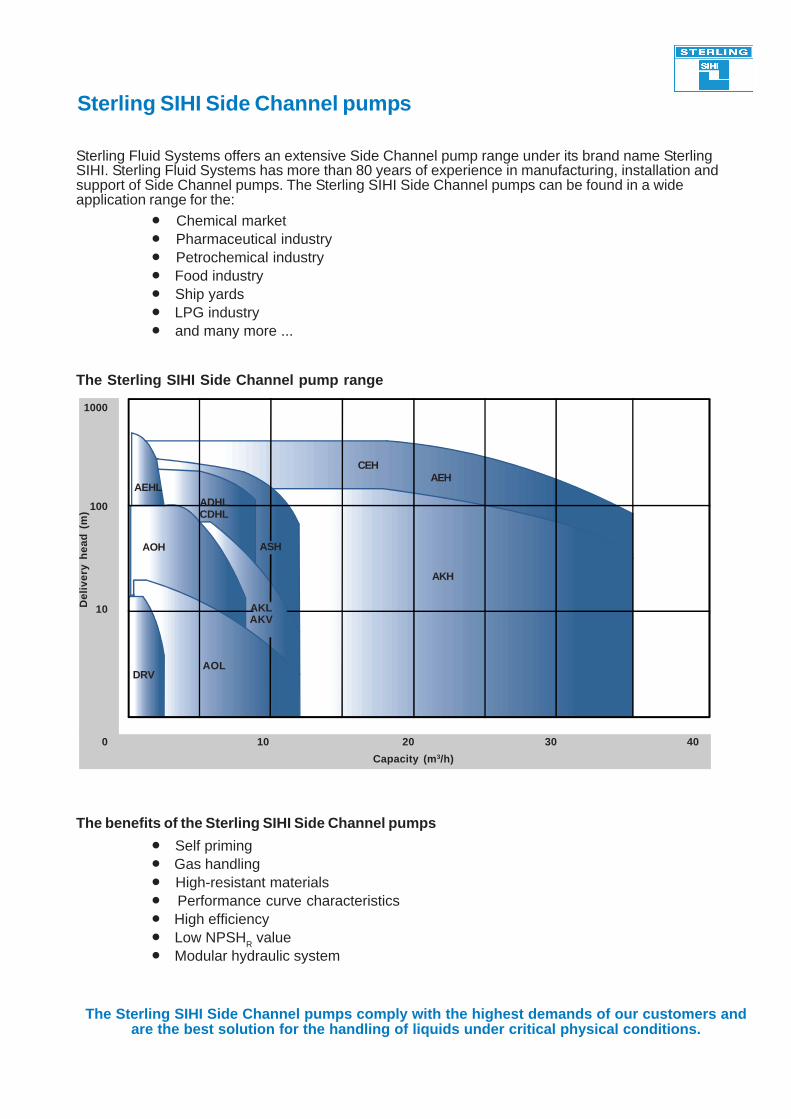
Sterling Fluid Systems offers an extensive Side Channel pump range under its brand name SterlingSIHI. Sterling Fluid Systems has more than 80 years of experience in manufacturing, installation andsupport of Side Channel pumps. The Sterling SIHI Side Channel pumps can be found in a wideapplication range for the:
The benefits of the Sterling SIHI Side Channel pumps
The Sterling SIHI Side Channel pumps comply with the highest demands of our customers andare the best solution for the handling of liquids under critical physical conditions.
• Self priming• Gas handling• High-resistant materials• Performance curve characteristics• High efficiency• Low NPSHR value• Modular hydraulic system
• Chemical market• Pharmaceutical industry• Petrochemical industry• Food industry• Ship yards• LPG industry• and many more ...
The Sterling SIHI Side Channel pump range
100
10
0 10 20 30 40
Del
iver
y h
ead
(m
)
Capacity (m3/h)
1000
AOL
ASH
AKH
AEHCEH
DRV
AOH
AKLAKV
ADHLCDHL
AEHL
Sterling Fluid Systems (Europe)
Sterling Fluid Systems (Americas)
Sterling Fluid Systems (Asia)
Sterling Fluid Systems (Austria)Wien
Telephone: +43 (0)1 680 050Fax: +43 (0)1 680 0521
E-Mail: [email protected]
Sterling Fluid Systems (France)Trappes
Telephone: +33 (0)1 34 82 39 00Fax: +33 (0)1 34 82 39 61
E-Mail: [email protected]
Sterling Fluid Systems (Greece)Athens
Telephone: +302 (0)10 9570783Fax: +0302 (0)10 9568121
E-Mail: [email protected]
Sterling Fluid Systems (Netherlands)Beverwijk
Telephone: +31 (0)251 263 232Fax: +31 (0)251 226 309
E-Mail: [email protected]
Sterling Fluid Systems (Schweiz)Schaffhausen
Telephone: +41 (0)52 6440606Fax: +41 (0)52 6440616
E-Mail: [email protected]
Sterling Fluid Systems (Belgium)Groot-Bijgaarden
Telephone: +32 (0)2 481 7711Fax: +32 (0)2 481 7737
E-Mail: [email protected]
Sterling SIHI (Germany)Itzehoe
Telephone: 49 (0)4821 77101Fax: 49 (0)4821 771274
E-Mail: [email protected]
Sterling Fluid Systems (Hungary)Veszprém
Telephone: +36 (0)88 40 66 33Fax: +36 (0)88 40 66 35
E-Mail: [email protected]
Sterling Fluid Systems (Polska)Warszawa
Telephone: +48 (0)22 849 7097Fax: +48 (0)22 849 6726
E-Mail: [email protected]
Sterling Fluid Systems (Spain)Madrid
Telephone: +34 (0)91 709 1310Fax: +34 (0)91 715 9700E-Mail: [email protected]
Sterling Fluid Systems (Chech Republic)Olomouc
Telephone: +420 (0)587 433 651Fax: +420 (0)587 433 653E-Mail: [email protected]
Sterling Fluid Systems (Italy)Monza
Telephone: +39 (0)039 2824 1Fax: +39 (0)039 2824 220
E-Mail: [email protected]
Sterling Fluid Systems (Romania)Bucuresti
Telephone: +40 (0)21 610 7188Fax: +40 (0)21 210 8287
E-Mail: [email protected]
Sterling SATDägeling, Germany
Telephone: +49 (0)4821 9000-0Fax: +49 (0)4821 9000-501E-Mail: [email protected]
Sterling Fluid Systems (UK)Altrincham/Cheshire
Telephone: +44 (0)161 9286371Fax: +44 (0)161 9252129
E-Mail: [email protected]
Sterling Fluid Systems (USA)Grand Island
Telephone: (1) 716 773 6450Fax: (1) 716 773 2330E-Mail: [email protected]
Sterling Fluid Systems (Canada)Guelph
Telephone: (1) 519 824 4600Fax: (1) 519 824 7250E-Mail: [email protected]
Sterling Fluid Systems (Asia)Singapore
Telephone: (65) 68630 828Fax: (65) 68630 868
E-Mail: [email protected]
Sterling Fluid Systems (Malaysia)Selangor Darul Ehsan
Telephone: (60) 3 8070 0198/99Fax: (60) 3 8070 0240
E-Mail: [email protected]
SIHI (Australia)Bayswater
Telephone: (61) 3 9720 1500Fax: (61) 3 9720 4076
E-Mail: [email protected]
Sterling Fluid Systems (Philippines)Muntinlupa City
Telephone: (63) 2 809 4908Fax: (63) 2 807 2013
E-Mail: [email protected]
Sterling Fluid Systems (China)Shanghai
Telephone: (8621) 6336 3488/6326 4171/6326 4062Fax: (8621) 63268487
E-Mail: [email protected]
Sterling Fluid Systems (Thailand)Bangkok
Telephone: (66) 2 319 2567Fax: (66) 2 319 25673/4
E-Mail: [email protected]
www.sterlingfluid.com