Embed Size (px)
Citation preview

SELF OPTIMIZING NETWORKS
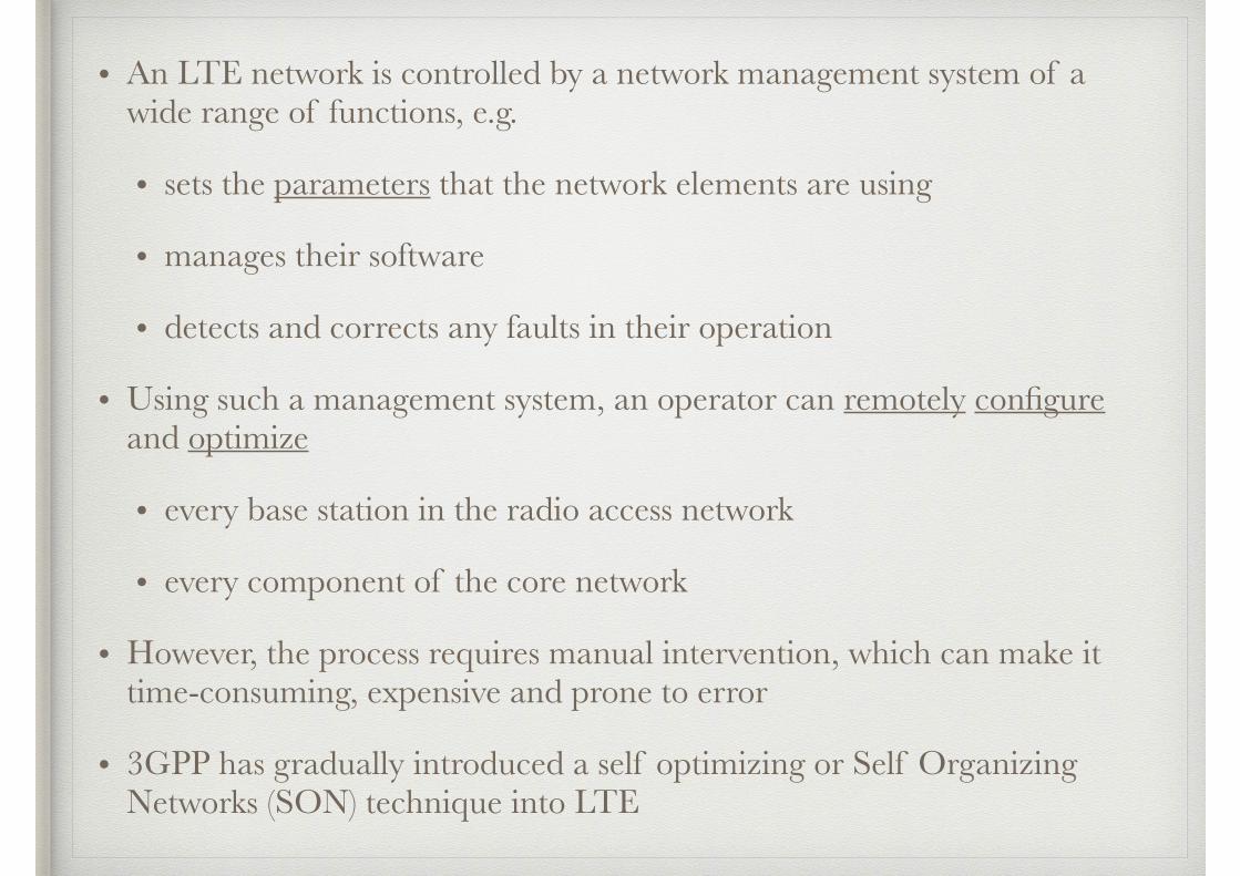
• An LTE network is controlled by a network management system of a wide range of functions, e.g.
• sets the parameters that the network elements are using
• manages their software
• detects and corrects any faults in their operation
• Using such a management system, an operator can remotely configure and optimize
• every base station in the radio access network
• every component of the core network
• However, the process requires manual intervention, which can make it time-consuming, expensive and prone to error
• 3GPP has gradually introduced a self optimizing or Self Organizing Networks (SON) technique into LTE
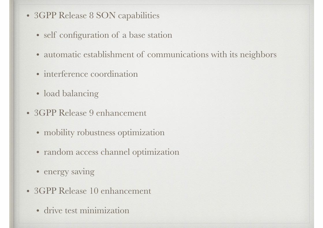
• 3GPP Release 8 SON capabilities
• self configuration of a base station
• automatic establishment of communications with its neighbors
• interference coordination
• load balancing
• 3GPP Release 9 enhancement
• mobility robustness optimization
• random access channel optimization
• energy saving
• 3GPP Release 10 enhancement
• drive test minimization
• Self optimizing networks are summarized in TR 36.902 and TS 36.300
• The main impact of SON is on the radio access network’s signaling procedures, notably the ones on the X2 interface
Contents
1. Self Optimizing Networks in Release 8
2. New Features in Release 9
3. Drive Test Minimization in Release 10
1. Self Optimizing Networks in Release 8
1.1 Self Configuration of an eNB
1.2 Automatic Neighbor Relations
1.3 Interference Coordination
1.4 Mobility Load Balancing
1.1 Self Configuration of an eNB• In LTE, a network operator can set up a new base station with minimal knowledge of the
outside world, which might include
• the domain name of the network management system
• the domain names of its MMEs and serving gateways
• The base station can acquire the other information it needs by a process of self configuration
• the base station contacts the management system and downloads the software it will require for its operation
• it also downloads a set of configuration parameters, e.g.,
• a tracking area code
• a list of PLMN identities
• the global cell identity
• maximum transmit power of each cell
• In the configuration parameters, the management system can explicitly assign a physical cell identity to each of the base station’s cells
• this places an unnecessary burden on the network planner, as every cell must have a different identity from any other cells that are nearby
• it also causes difficulties in networks that contain home base stations, which can be sited without any knowledge of their neighbors at all
• as an alternative, the management system can simply give the base station a short list of allowed physical cell identities
• the base station then chooses a physical cell identity at random from the ones that remain
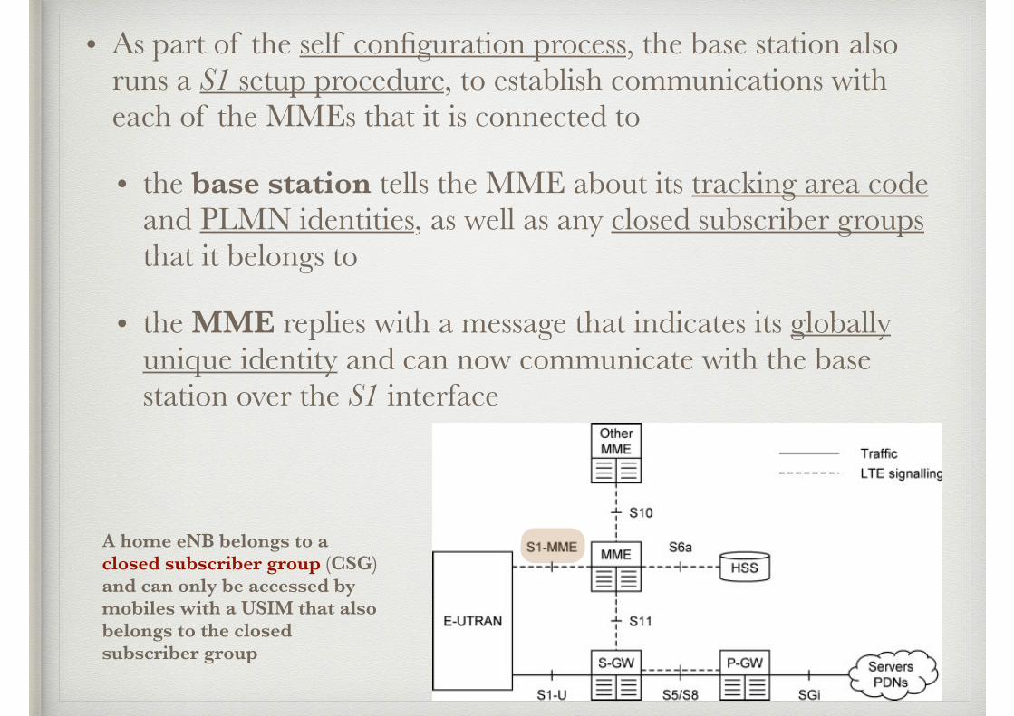
• As part of the self configuration process, the base station also runs a S1 setup procedure, to establish communications with each of the MMEs that it is connected to
• the base station tells the MME about its tracking area code and PLMN identities, as well as any closed subscriber groups that it belongs to
• the MME replies with a message that indicates its globally unique identity and can now communicate with the base station over the S1 interface
A home eNB belongs to a closed subscriber group (CSG) and can only be accessed by mobiles with a USIM that also belongs to the closed subscriber group
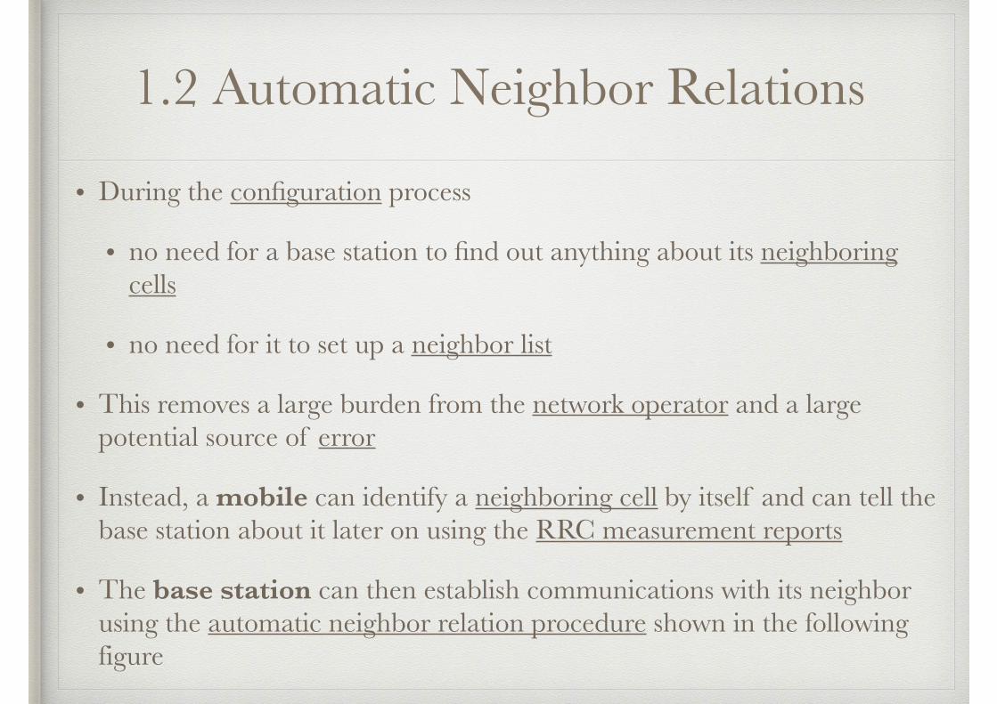
1.2 Automatic Neighbor Relations
• During the configuration process
• no need for a base station to find out anything about its neighboring cells
• no need for it to set up a neighbor list
• This removes a large burden from the network operator and a large potential source of error
• Instead, a mobile can identify a neighboring cell by itself and can tell the base station about it later on using the RRC measurement reports
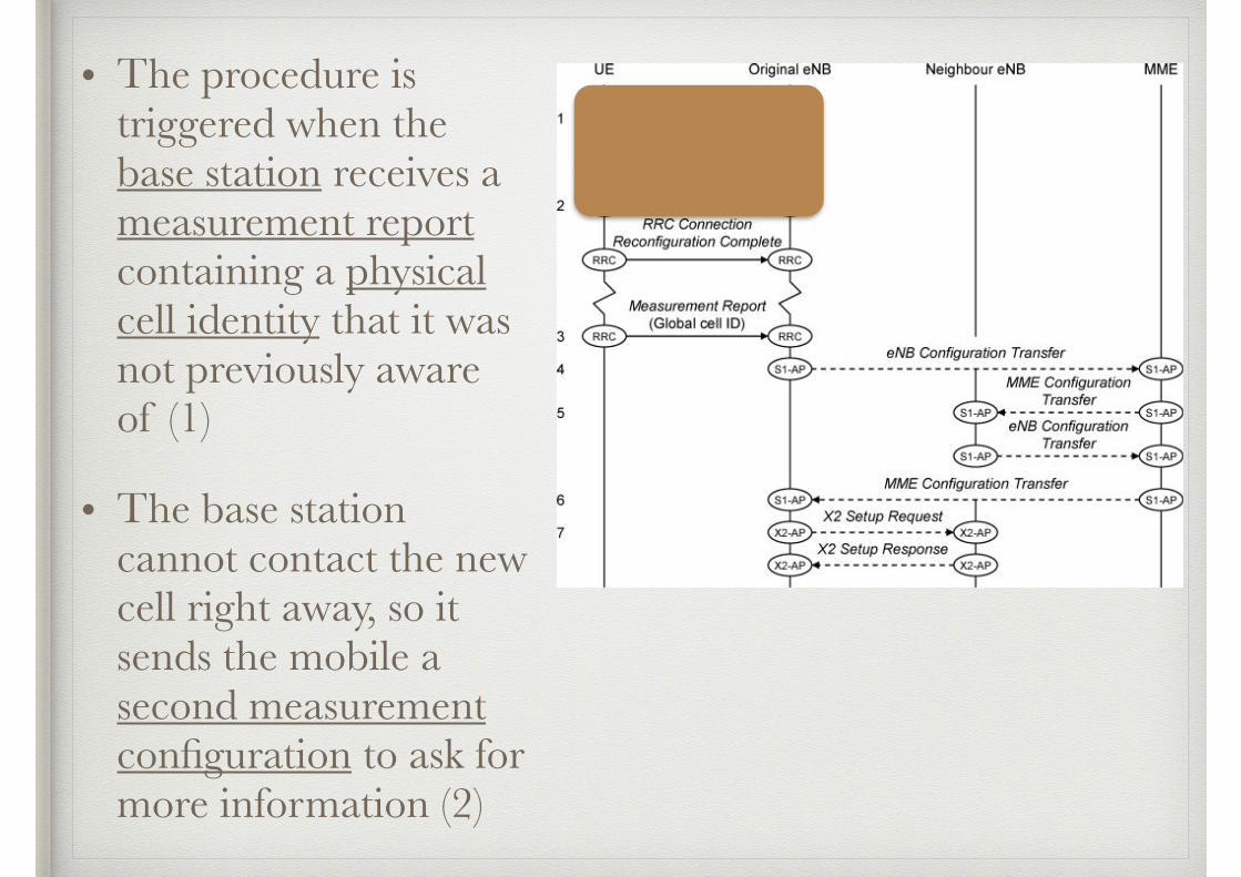
• The base station can then establish communications with its neighbor using the automatic neighbor relation procedure shown in the following figure
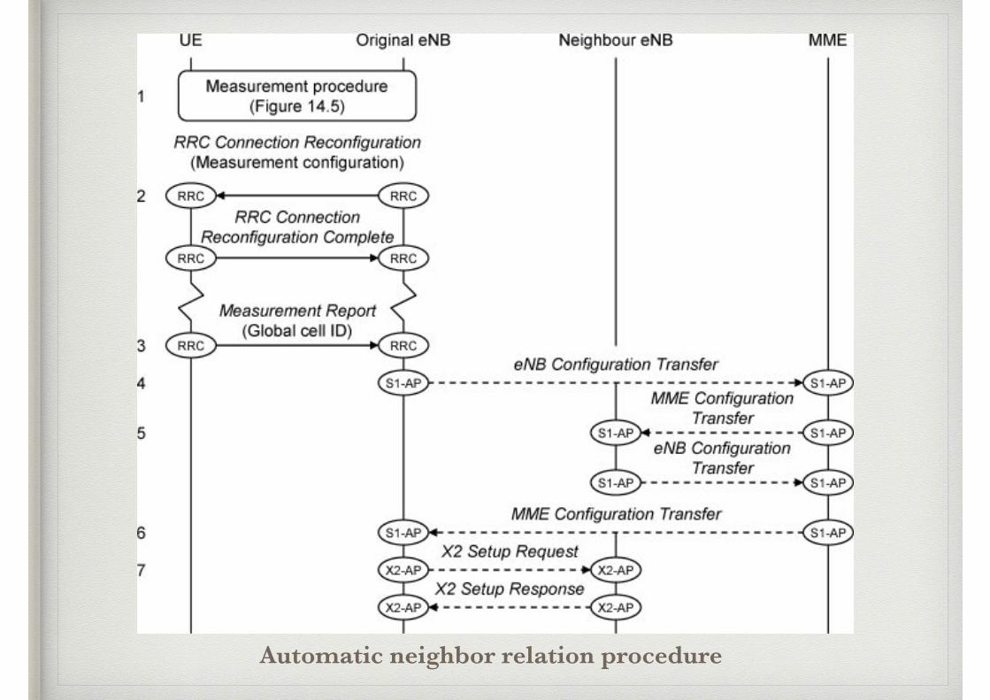
Automatic neighbor relation procedure
• The procedure is triggered when the base station receives a measurement report containing a physical cell identity that it was not previously aware of (1)
• The base station cannot contact the new cell right away, so it sends the mobile a second measurement configuration to ask for more information (2)
• In response, the mobile reads the neighboring cell’s system information and returns its global cell identity, tracking area code and PLMN list in a second measurement report (3)
• The base station now has enough information to initiate an S1 based handover to the new cell
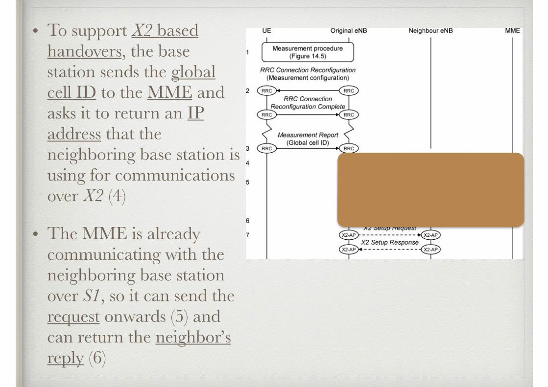
• To support X2 based handovers, the base station sends the global cell ID to the MME and asks it to return an IP address that the neighboring base station is using for communications over X2 (4)
• The MME is already communicating with the neighboring base station over S1, so it can send the request onwards (5) and can return the neighbor’s reply (6)

• The two base stations can now establish communications across the X2 interface (7), using X2 setup procedure
• During this procedure, the base stations exchange information about all the cells they are controlling, including their
• global cell identities
• physical cell identities
• carrier frequencies
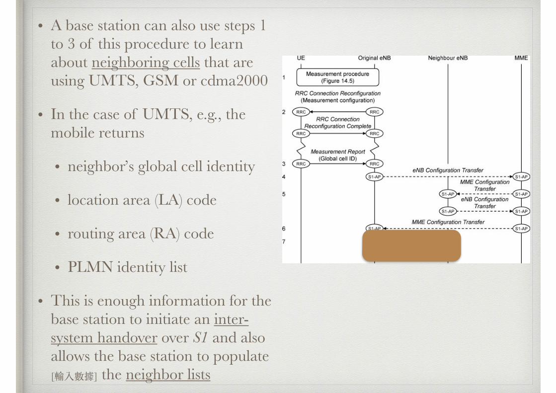
• A base station can also use steps 1 to 3 of this procedure to learn about neighboring cells that are using UMTS, GSM or cdma2000
• In the case of UMTS, e.g., the mobile returns
• neighbor’s global cell identity
• location area (LA) code
• routing area (RA) code
• PLMN identity list
• This is enough information for the base station to initiate an inter-system handover over S1 and also allows the base station to populate [輸入數據] the neighbor lists
1.3 Interference Coordination
• The X2-AP Load Indication procedure helps a network to minimize the interference between neighboring base stations and to implement the fractional frequency reuse schemes
• To use the procedure, a base station sends an X2-AP Load Information message to one of its neighbors
• In the message, it can include three information elements for each cell that it is controlling
(1) describes the transmitted power in every downlink resource block
• the neighbor can use this information in its scheduling procedure, by avoiding downlink transmissions to distant mobiles in resource blocks that are subject to high levels of downlink interference
(2) describes the interference that the base station is receiving in every uplink resource block
• the neighbor can use this in a similar way, so that it does not schedule uplink transmissions from distant mobiles in resource blocks that are subject to high uplink interference
(3) a list of uplink resource blocks in which the base station intends to schedule distant mobiles
• here, the second base station is expected to avoid scheduling uplink transmissions from distant mobiles in those resource blocks, so that it does not return high levels of uplink interference to the first base station
1.4 Mobility Load Balancing
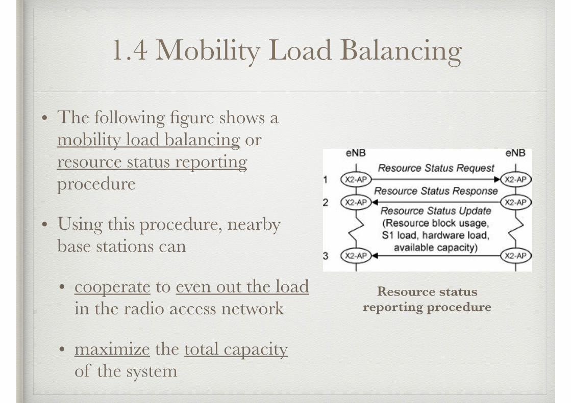
• The following figure shows a mobility load balancing or resource status reporting procedure
• Using this procedure, nearby base stations can
• cooperate to even out the load in the radio access network
• maximize the total capacity of the system
Resource status reporting procedure
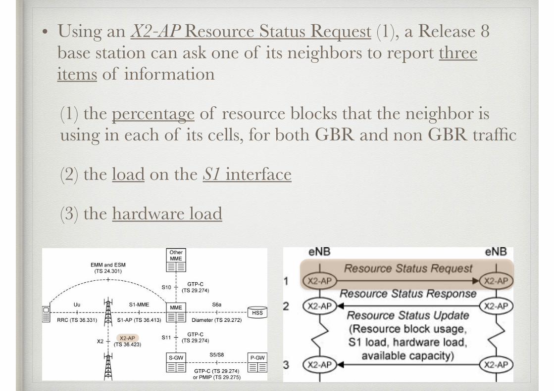
• Using an X2-AP Resource Status Request (1), a Release 8 base station can ask one of its neighbors to report three items of information
(1) the percentage of resource blocks that the neighbor is using in each of its cells, for both GBR and non GBR traffic
(2) the load on the S1 interface
(3) the hardware load
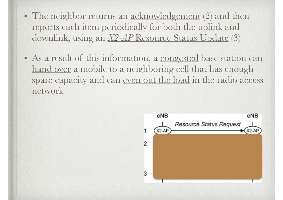
• The neighbor returns an acknowledgement (2) and then reports each item periodically for both the uplink and downlink, using an X2-AP Resource Status Update (3)
• As a result of this information, a congested base station can hand over a mobile to a neighboring cell that has enough spare capacity and can even out the load in the radio access network
• Release 9 adds two enhancements
(1) the neighbor reports a fourth field in its Resource Status Update, the composite available capacity group, which indicates the capacity that it has available for load balancing purposes on the uplink and downlink
• the original base station can use this information to assist its handover decision
(2) Secondly, there is a risk after such a handover that the new base station will hand the mobile straight back to the old one
• to prevent this from happening, Release 9 introduces a X2 mobility settings change procedure
• using this procedure, a base station can ask a neighbor to adjust the thresholds that it is using for measurement reporting, by means of the cell specific offsets
• after the adjustment, the mobile should stay in the target cell, instead of being handed back
• Release 10 adds one enhancement
• using an S1 direct information transfer procedure, a base station can initiate the exchange of radio access network information management (RIM) information with a UMTS or GSM neighbor
• the information includes the composite available capacity group in the case of an LTE cell and the cell load information group in the case of the other technologies
• this information can trigger a load balancing handover to a UMTS or GSM neighbor
2. New Features in Release 9
2.1 Mobility Robustness Optimization
2.2 Random Access Channel Optimization
2.3 Energy Saving
2.1 Mobility Robustness Optimization
• Mobility robustness optimization is a self optimization technique that first appears in Release 9
• Using this technique, a base station can gather information about any problems that have arisen due to the use of unsuitable measurement reporting thresholds
• It can then use the information to adjust the thresholds it is using and to correct the problem
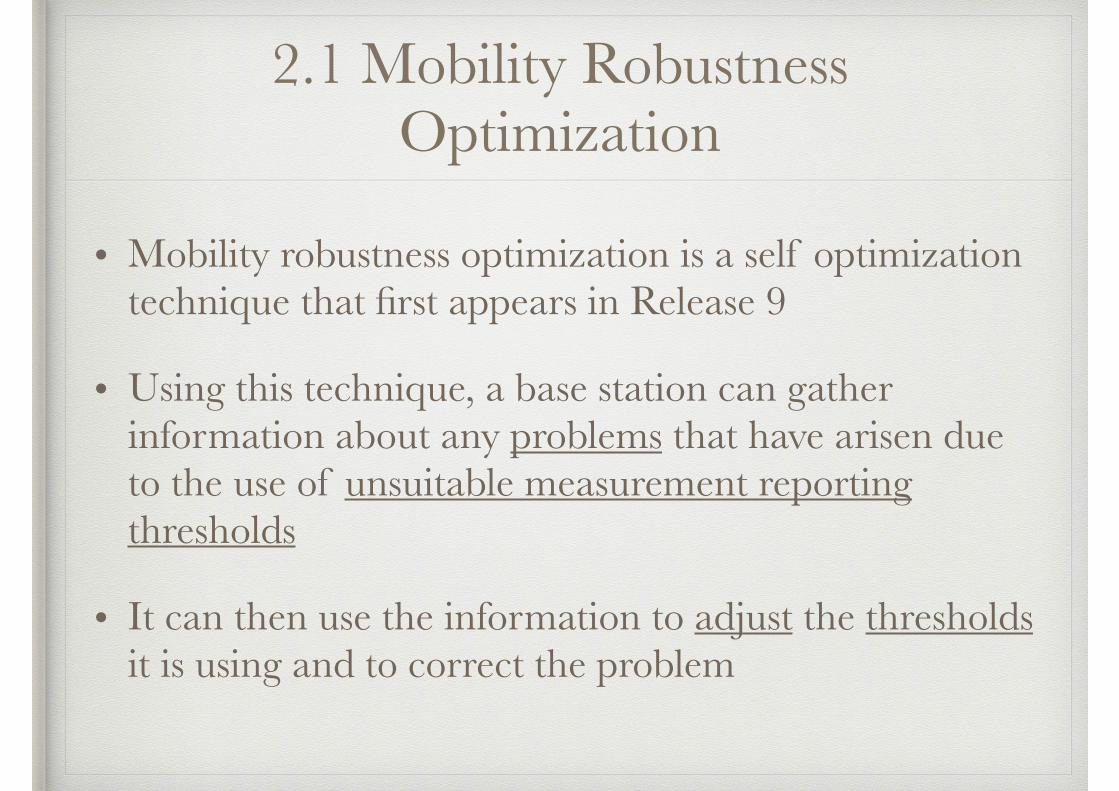
• There are three main causes of trouble, the first of which is shown in the figure
• the base station has started a handover to a new cell (1) but it has done this too late, because its measurement reporting thresholds have been poorly set
• alternatively, it may not have started the handover at all
• before any handover is executed, the mobile’s received signal power falls below a threshold and its radio link fails (2)
Mobility robustness optimization, triggered by a handover that was too late
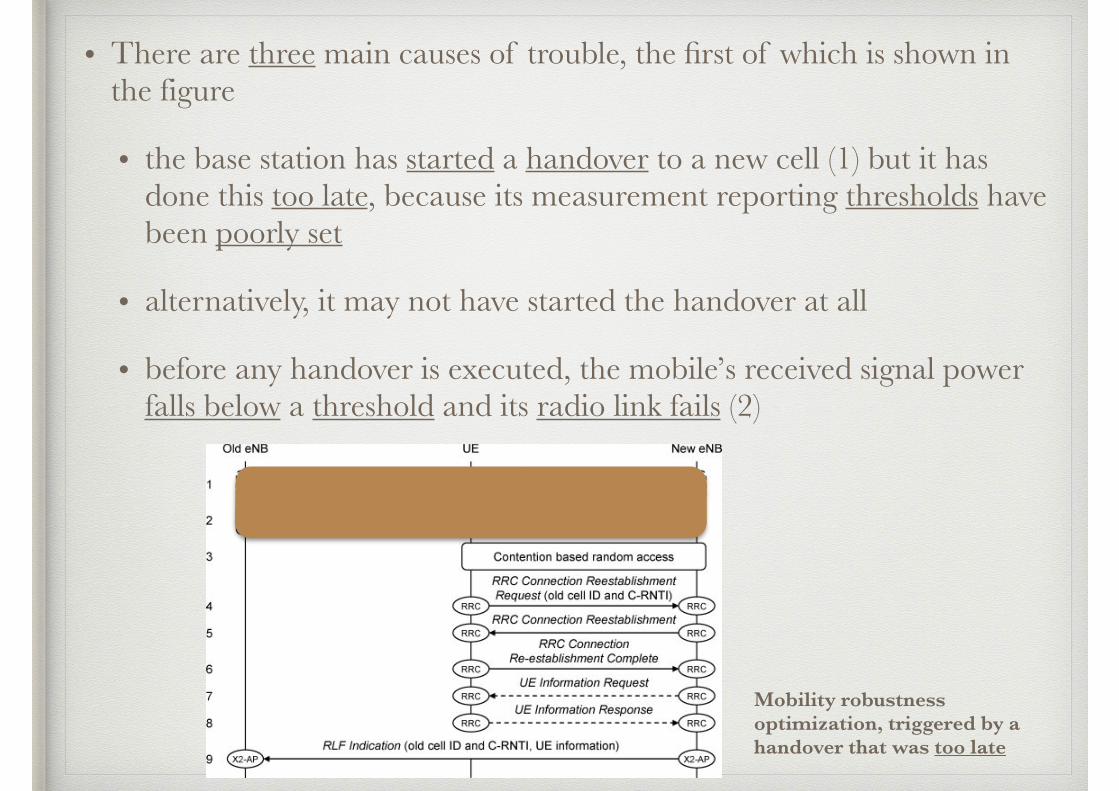
• in response, the mobile runs the cell selection procedure and discovers the cell that it should have been handed to
• it contacts the new cell using the random access procedure (3) and a RRC connection reestablishment procedure (4, 5, 6), in which it identifies itself using the old cell’s physical cell ID and its old C-RNTI [C-RNTI:Cell Radio Network Temporary Identifier]
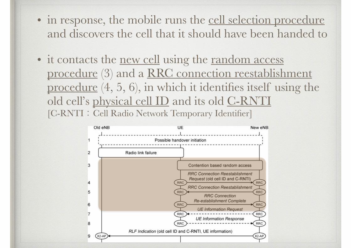
• in step 6, the mobile can also indicate that it has measurements from immediately before the radio link failure of the power received from the old cell and its neighbors
• if it does, then the base station retrieves this information using an RRC UE Information procedure (7, 8)
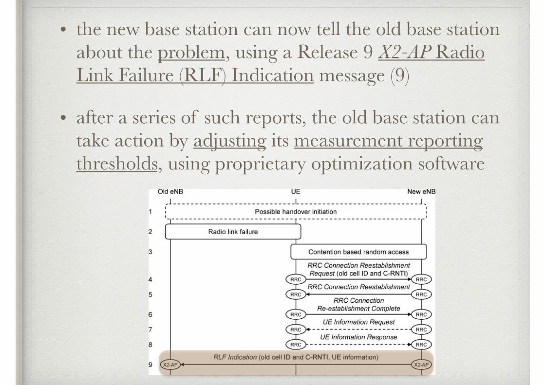
• the new base station can now tell the old base station about the problem, using a Release 9 X2-AP Radio Link Failure (RLF) Indication message (9)
• after a series of such reports, the old base station can take action by adjusting its measurement reporting thresholds, using proprietary optimization software
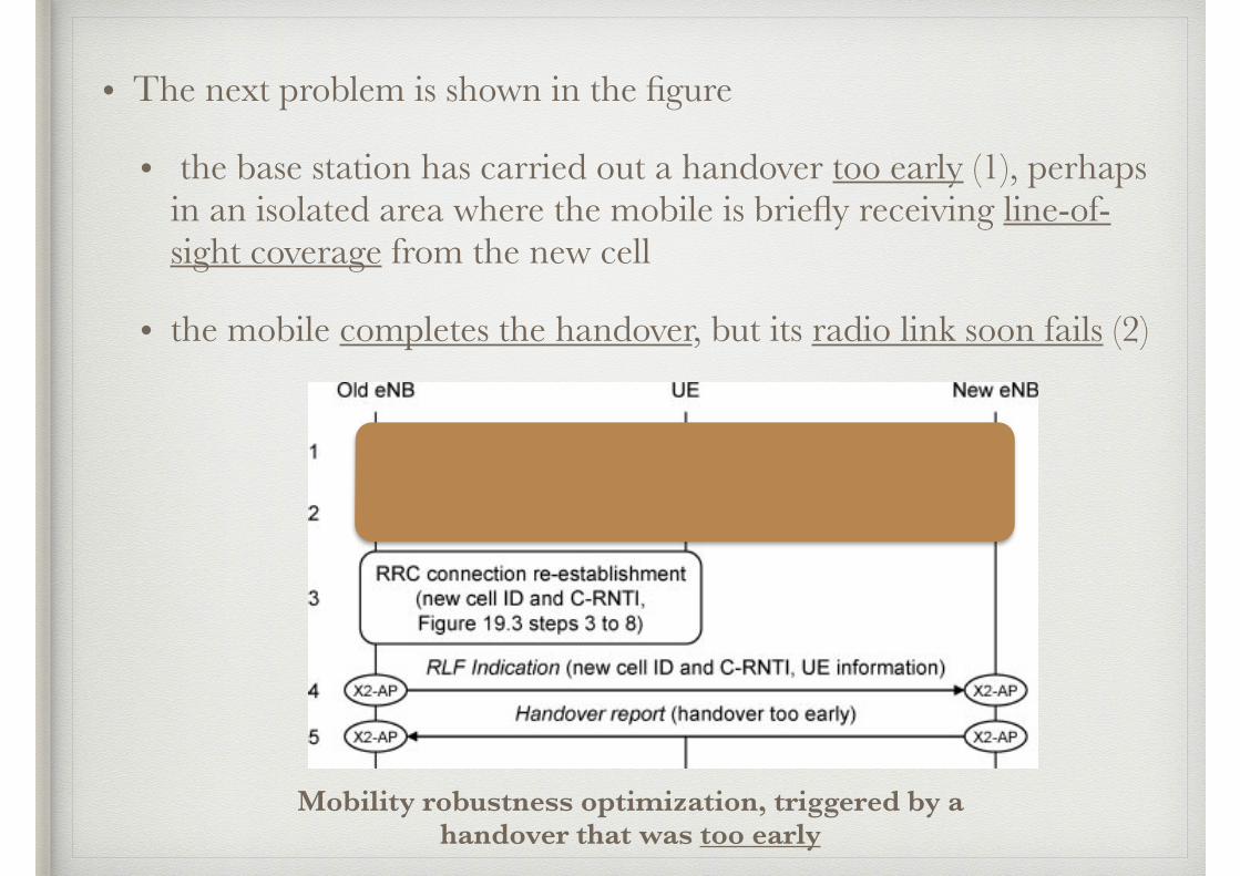
• The next problem is shown in the figure
• the base station has carried out a handover too early (1), perhaps in an isolated area where the mobile is briefly receiving line-of-sight coverage from the new cell
• the mobile completes the handover, but its radio link soon fails (2)
Mobility robustness optimization, triggered by a handover that was too early
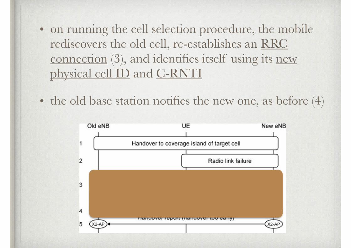
• on running the cell selection procedure, the mobile rediscovers the old cell, re-establishes an RRC connection (3), and identifies itself using its new physical cell ID and C-RNTI
• the old base station notifies the new one, as before (4)
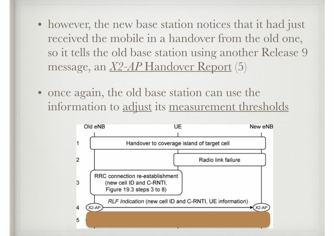
• however, the new base station notices that it had just received the mobile in a handover from the old one, so it tells the old base station using another Release 9 message, an X2-AP Handover Report (5)
• once again, the old base station can use the information to adjust its measurement thresholds
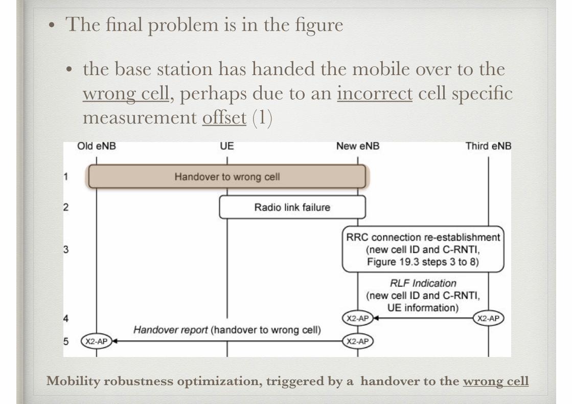
• The final problem is in the figure
• the base station has handed the mobile over to the wrong cell, perhaps due to an incorrect cell specific measurement offset (1)
Mobility robustness optimization, triggered by a handover to the wrong cell
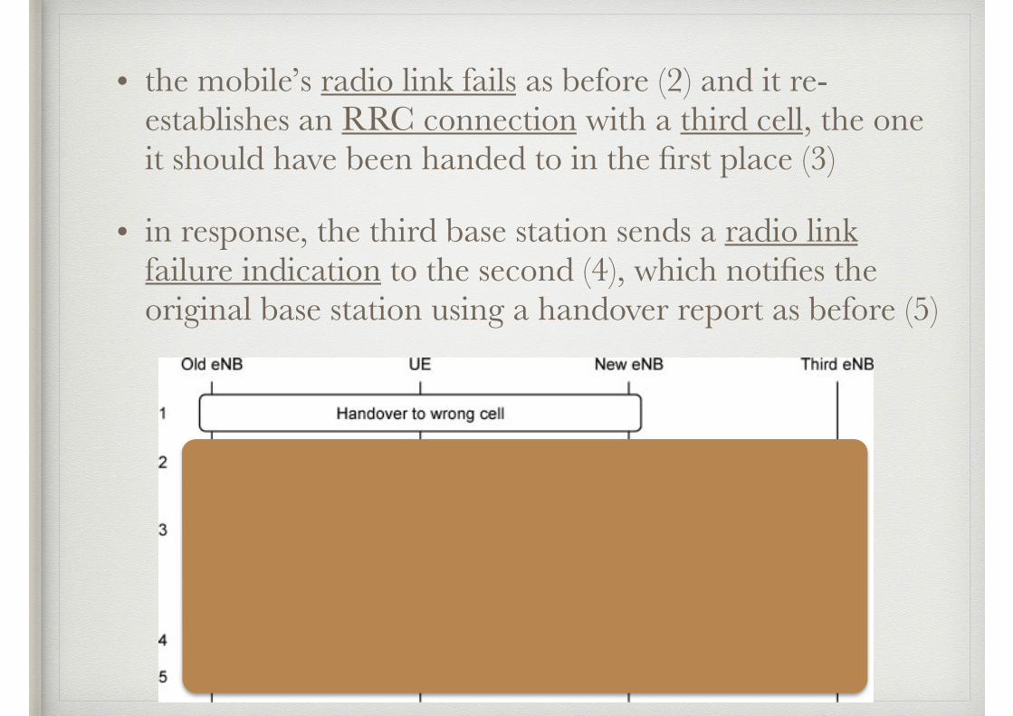
• the mobile’s radio link fails as before (2) and it re-establishes an RRC connection with a third cell, the one it should have been handed to in the first place (3)
• in response, the third base station sends a radio link failure indication to the second (4), which notifies the original base station using a handover report as before (5)
• Mobility robustness optimization is enhanced in Release 10, to let the system detect unnecessary handovers to another radio access technology
• after a handover to UMTS or GSM, the new radio access network can ask the mobile to continue measuring the signal power that it is receiving from nearby LTE cells
• if the signal power is sufficiently high, then the network can tell the LTE base station that it triggered the handover unnecessarily, using the S1-AP direct information transfer procedure
• as before, the base station can use a series of such reports to adjust its measurement reporting thresholds
2.2 Random Access Channel Optimization
• A base station can gather two types of information to help it optimize the random access channel
(1) the base station can use the RRC UE information procedure to retrieve information about a mobile’s last successful random access attempt
• the information includes the number of preambles that the mobile sent before receiving a reply and an indication of whether the contention resolution procedure failed at any stage
• using this information, the base station can adjust the random access channel’s power settings and resource block allocations, so as to minimize the load that the channel makes on the air interface
(2) neighboring base stations can exchange information about the parameters that they are using for the random access channel, during the X2 setup procedure
• the information includes
• PRACH frequency offset and PRACH configuration index, which determine the resource blocks that the channel is using
• root sequence index, which determines the cell’s choice of random access preambles
• using this information, the base stations can minimize the interference between random access transmissions in nearby cells, by allocating them different sets of resource blocks and different preambles
• Note: preamble
• a preamble is a signal used in network communications to synchronize transmission timing between two or more systems
• in wireless transmissions, the radio preamble (also called a header) is a section of data at the head of a packet.
• the length of the preamble can affect the time it takes to transmit data by increasing the packet overhead
2.3 Energy Saving
• Save energy is achieved by switching off cells that are not being used
• A typical situation is the use of picocells in a shopping centre, in which a cell can be switched off outside shopping hours if it only contributes to the network’s capacity, but not to its coverage
• If a base station supports this feature, then it can decide to switch the cell off after a long period of low load
• To do this, it hands any remaining mobiles over to cells that have overlapping coverage, tells them about the change using an X2-AP eNB Configuration Update and switches the cell off
• The base station itself remains switched on, so, at a later time, a neighbor can ask the base station to switch the cell on again using an X2-AP Cell Activation Request
3. Drive Test Minimization in Release 10
• Network operators have traditionally assessed the coverage of a radio access network by transporting measurement devices around its intended coverage area, using a drive testing technique
• As well as being time-consuming and expensive, this technique provides coverage data that are limited to the route of the drive test and supplies little or no information about coverage indoors
• Network operators do, however, have another ready supply of measurement devices in the form of the users’ mobiles
• Using a minimization of drive tests (MDT) technique, an operator can ask its mobiles to return measurements that supplement or even replace the ones obtained from traditional drive testing
• As part of the customer care process, the operator is obliged to obtain the users’ consent for using their mobiles in drive test minimization
• The network stores the relevant information in the home subscriber server (HSS) and checks it before measurement activation
• If the user does consent, then two measurement modes are available
• immediate measurements for mobiles in RRC_CONNECTED state
• logged measurements for mobiles in RRC_IDLE
• Immediate measurements
• the mobile measures the downlink RSRP or RSRQ and reports these quantities to the base station along with any location data that it has available[RSRP:Reference Signal Received Power, RSRQ:Reference Signal Received Quality]
• the base station can then return the information to the management system, using the existing network management procedures for trace reporting
• Logged measurements
• a base station can also send an RRC Logged Measurement Configuration message to an active mobile, to configure it for logged measurements once it enters RRC_IDLE
• in idle mode, the mobile makes its measurements with a period that is a multiple of the discontinuous reception cycle
• it then stores the information in a log, along with time stamps and any location data that it has available
• when the mobile next establishes an RRC connection, it can signal the availability of its measurement log using a field in the message RRC Connection Setup Complete
• the base station can then retrieve the logged measurements from the mobile using the RRC UE Information procedure and can forward them to the management system as before