Embed Size (px)
Citation preview
Full Terms & Conditions of access and use can be found athttp://www.tandfonline.com/action/journalInformation?journalCode=utrb20
Download by: [Brunel University London] Date: 30 March 2016, At: 02:34
Tribology Transactions
ISSN: 1040-2004 (Print) 1547-397X (Online) Journal homepage: http://www.tandfonline.com/loi/utrb20
NFAL Prototype Design and Feasibility Analysis forSelf-Levitated Conveyor Belt
Xiaoni Chang, Bin Wei, M. Atherton, Keyan Ning, C. Mares & T. Stolarski
To cite this article: Xiaoni Chang, Bin Wei, M. Atherton, Keyan Ning, C. Mares & T. Stolarski(2016): NFAL Prototype Design and Feasibility Analysis for Self-Levitated Conveyor Belt,Tribology Transactions, DOI: 10.1080/10402004.2015.1124306
To link to this article: http://dx.doi.org/10.1080/10402004.2015.1124306
Accepted author version posted online: 16Mar 2016.
Submit your article to this journal
Article views: 11
View related articles
View Crossmark data
ACCEPTED MANUSCRIPT
ACCEPTED MANUSCRIPT 1
NFAL Prototype Design and Feasibility Analysis for Self-Levitated Conveyor Belt
Xiaoni Chang1, Bin Wei
2 , M. Atherton
3, Keyan Ning
4. C. Mares
3, T. Stolarski
3
1School of Economic and Management, Beihang University, Beijing, China,100191
2 State Key Laboratory of Tribology, Tsinghua University, Beijing, China 100084
3.College of Engineering, Design and Physical Sciences, Brunel University, UK
4. National Key Laboratory of Vehicle Transmission, China North Vehicle Research Institute,
Beijing 100072, China
Abstract:In order to avoid friction and scratch of the cans on the conveyor belt, an acoustic
levitation prototype was designed, so as to verify the feasibility in the can transportation. The
modal shapes and the forced harmonic shapes of the prototype are obtained by the ANSYS
coupled field computation with ¼ symmetry model and the levitation capacity was carried out by
the use of groups of stimulation and test instruments. The simulation results showed that the pure
flexural and mixed flexural wave shapes with different wave number existed at some specific
frequency. The amplitude in the central point can only be stimulated when resonant in few
frequencies by the four piezo-electric disks that are glued at the bottom of the aluminium plate,
which can be observed in the frequency spectrum. The experimental results confirmed the
theoretical results and the feasibility of the prototype, the same time, confirmed that objects can
be floated in several resonant frequencies under forced vibrating condition. The situation that the
system can provide largest bearing capacity is when both the piezo-electric disc and the plate
could vibrate resonantly at the same time.
Keywords: NFAL; ANSYS; Prototype; Resonant; Piezoelectric
Corresponding author. [email protected]
Dow
nloa
ded
by [
Bru
nel U
nive
rsity
Lon
don]
at 0
2:34
30
Mar
ch 2
016
ACCEPTED MANUSCRIPT
ACCEPTED MANUSCRIPT 2
1 Introduction
The NFAL (Near Field Acoustic Levitation) concept is come from the high frequency gas
squeeze theory. The gas squeeze theory is originally proposed by Gross[1]
and improved by
Langlois[2]
. Next, E.O.J.Salbu[3]
proposed the fixed object squeeze film model and believed that
the squeeze film characteristics is similar with the piston exciting situation. The carrying
capacity can be obtained by simple calculation. The free levitation theory is first proposed by
Beck JV[4]
and numerical method is applied in his model. Later, the research about squeeze film
characteristics which was solved by lubrication dynamic methods was developed for
years[ 5 , 6 ]
.Based on free levitation theory, the modal shapes was considered in
Yoshiki.Hashimoto's research[7]
. The excited shape was supposed ideal flexural wave and the
film thickness equation was coupled by it. The model was proved to be more stable and higher
bearing capacity than that in the rigid disk excitation condition. Later, the linearization solution
was derived by Minikes and Bucher[8]
and the feasibility was verified by Yoshiki.Hashimoto's
experiments results. Stolaski and Wei Chai investigated the characteristics of the designed linear
bearing, and then, the 2D model for the new bearing was established gradually
[9,10].LI jin, LIU
Pinkuan etc[11,12]
researched the bearing force in experiments and achieved the film thickness
curves versus frequencies. Recently, some scholars combined the squeeze film theory with
ultrasonic phenomenon [13]-[16]
and compared the ultrasonic levitation results with squeeze film
by numerical computation. Thus, the concept 'ultrasonic squeeze film' was proposed and the
theory was further developed. Recently, from the point of view of engineering practice, lots of
researchers focus on some typical situations of the squeeze film such as the Non Newtonian fluid
Dow
nloa
ded
by [
Bru
nel U
nive
rsity
Lon
don]
at 0
2:34
30
Mar
ch 2
016
ACCEPTED MANUSCRIPT
ACCEPTED MANUSCRIPT 3
film, the film with porous layer, damping effect and so on[17]-[19]
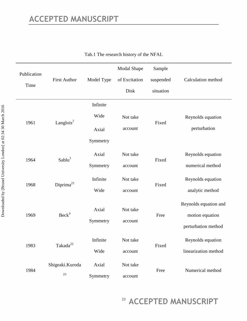
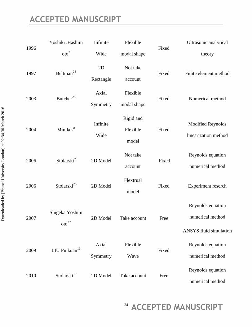
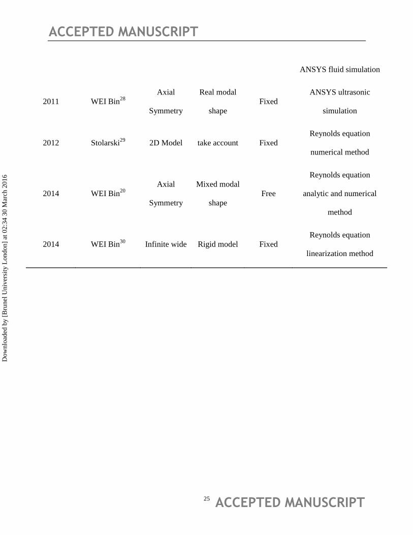
.The whole research histories for
the near field acoustic Levitation are listed in Tab.1.
The listed table showed different model and solution method for the NFAL system. Aiming at
the model forms, there are three main models for the NFAL system; they are infinite width
model for simply estimating, axial Symmetry model for the round exciting disc and 2-D model
for common exciting plate. All of the modal shapes, including rigid, pure flexible, mixed (true)
models and object status could influence the complex extent of the mathematic models. The
solutions corresponding to the models mainly included acoustic radial field and squeeze film
methods, however, for the free object only can the model solved by the numerical way.
In the engineering practice, the horn is helpful to the actuator design [20]
. But due to the space
constraints, the designable horn cannot be used in the conveyor self-levitation system, so the
resonance frequency of the system is difficult to predict and affected a lot by the layout of the
piezo-discs.
2 Prototype Design
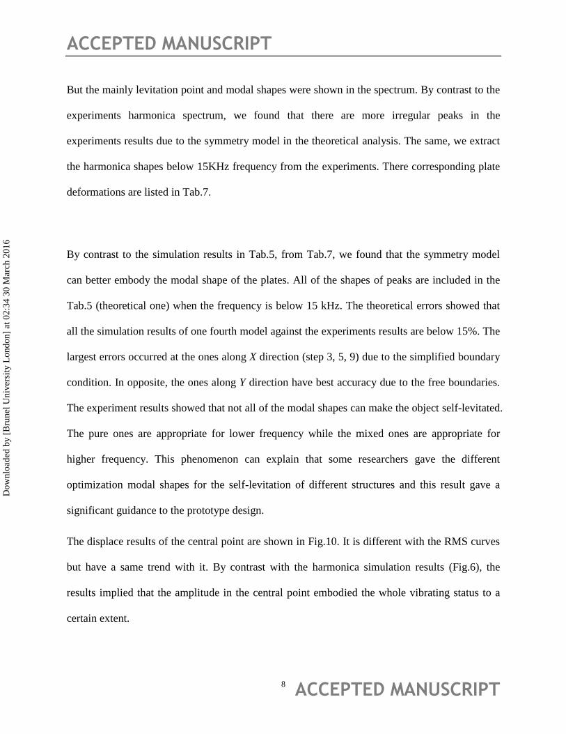
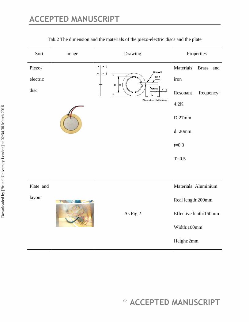
The real physical NFAL platform and the levitated samples are shown in Fig.1. The dimension
and the materials of the piezo-electric discs and the exciting plate are listed in Tab.2. The four
piezo-electric discs are connected with the output port of the amplifier by the block terminal with
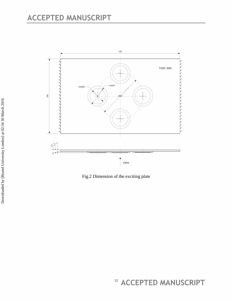
a 1 Ampere fuse. The layout of piezo-electric discs is shown in Fig.2.
The piezo-electric discs are fixed at the bottom of the plate with professional glue, and then a
distress treatment lasted for 12 hours. So, the prototype of the actuator (exciting plate) is made
up of the plate and the piezo-electric discs which can eradiate sonic field and squeeze the gas
Dow
nloa
ded
by [
Bru
nel U
nive
rsity
Lon
don]
at 0
2:34
30
Mar
ch 2
016
ACCEPTED MANUSCRIPT
ACCEPTED MANUSCRIPT 4
which is close to the plate surface. In this circuit, the capacitances are parallel connected, whose
resonant frequency is determined by the total capacitances and equivalent inductances. The
system characteristics are concerned more than the single piezoelectric disc. The system
resonance frequency and impedance are more important to the levitation capacity than the
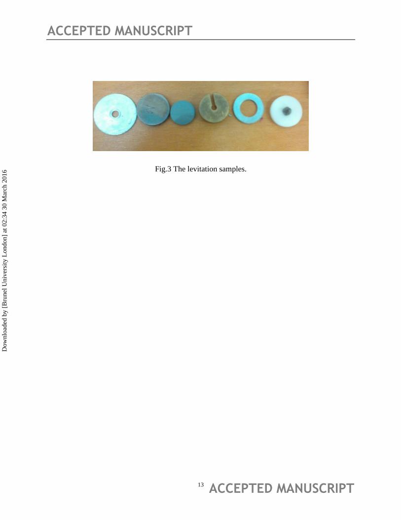
properties of the piezoelectric discs. Many kinds of levitation samples including metallic and
non-metallic are chosen to test the levitation effects in the experiment. The designed plate
actuator is shown in Fig.3. The floating objects on the plate can be self-levitated by the effect of
NFAL.
3. The plate finite element and the squeeze film model of the piezoelectric plate actuator
Due to the air pressure boundary condition is neglected in the FEM model of the exciting pate, it
is reasonable to calculate the modal and harmonica shapes first, and then obtain the accurate film
thickness equations coupled with the plate shapes, by which, calculate the bearing force (nodes
pressure) by the Reynolds equation coupled with the film thickness equation.
3.1 The Finite element model of the exciting plate
The deforming shapes of the plate actuator can be carried out by the finite elements model. The
mathematical model is determined by the geometric dimensions of the plate and the piezoelectric
discs (Fig.2). The FEM vibration model for PZT-4 was researched theoretically and
experimentally. It was proved to be accurate of the ANSYS FEM model by comparing the results
of disc excitation experiments [20]
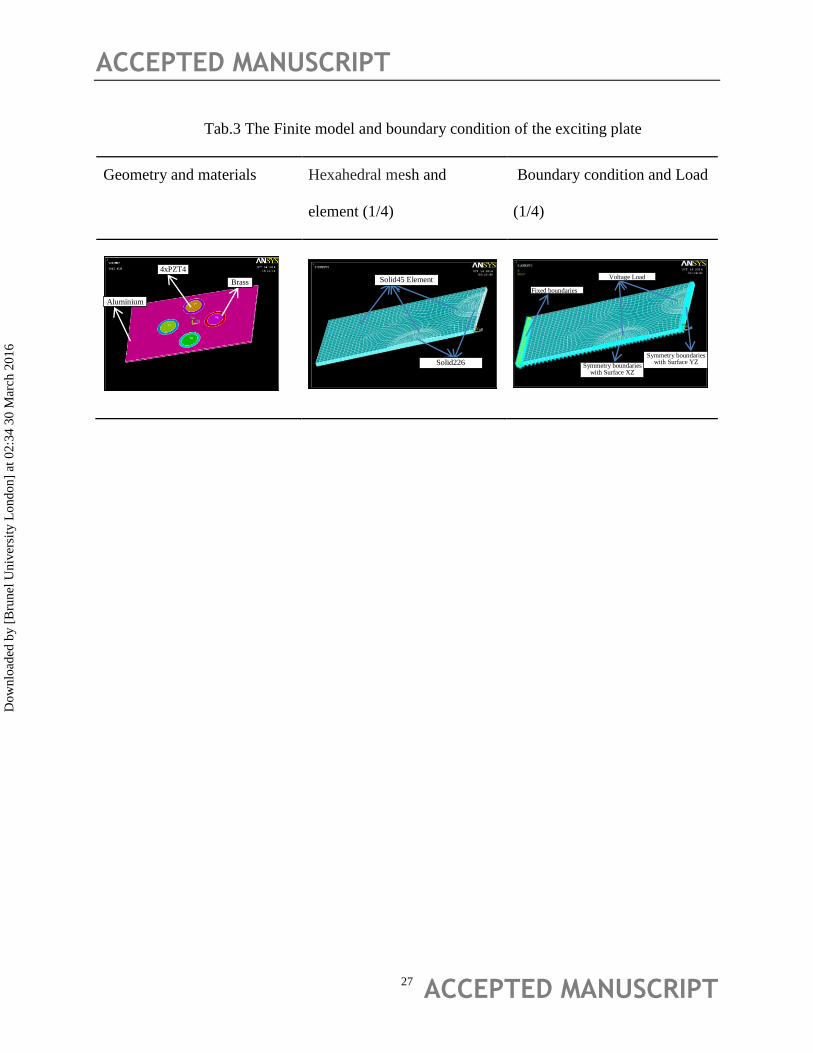
. The finite element model and boundary condition of the
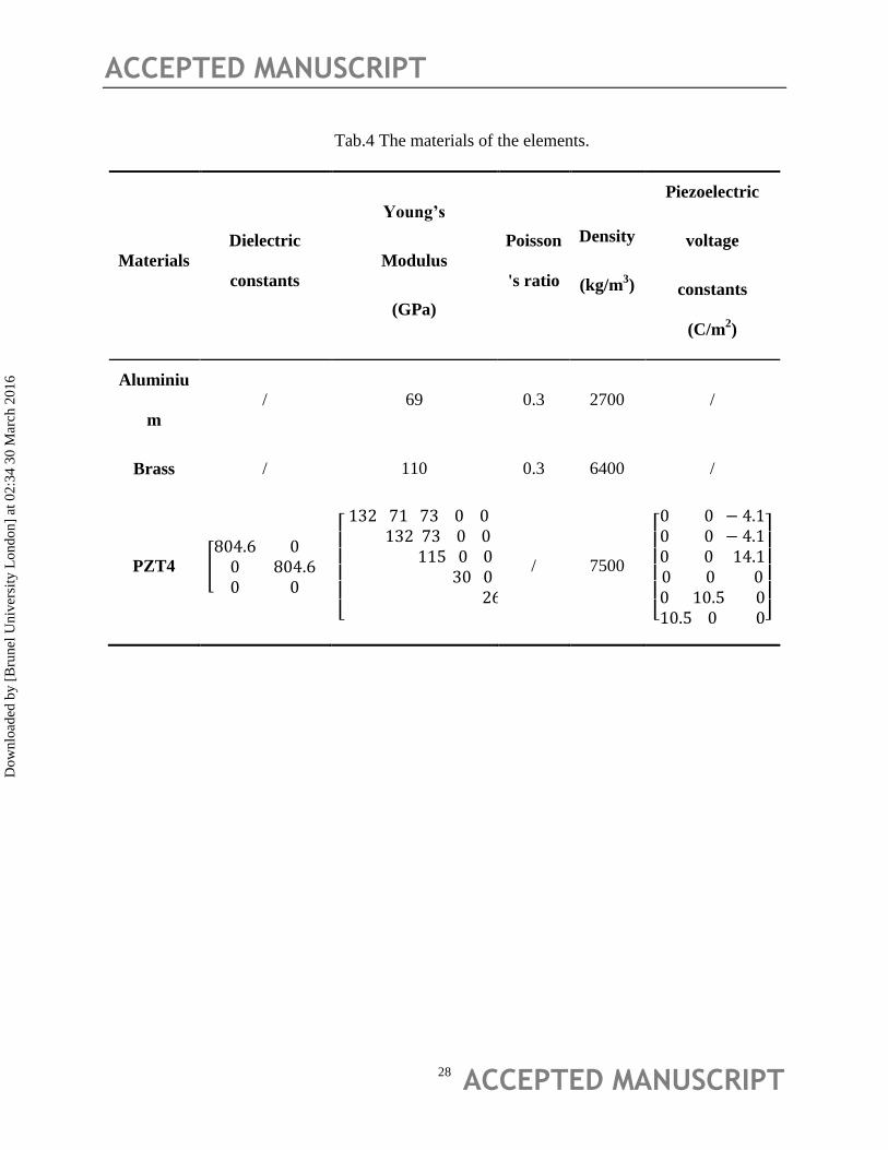
exciting plate are shown in Tab.3. The materials parameters are listed in Tab.4. The model
coupled with electric-structure would be better simulating the real experiment status. Three
Dow
nloa
ded
by [
Bru
nel U
nive
rsity
Lon
don]
at 0
2:34
30
Mar
ch 2
016
ACCEPTED MANUSCRIPT
ACCEPTED MANUSCRIPT 5
materials are included, that is aluminium, brass linings and PZT4 which are glued with each
other in the ANSYS Pre-treatment. In the Engineering practice, the symmetry modal shapes
(either with XZ or YZ plane) are available to ensure the cans are able to steadily self-levitation in
the central area on the conveyor belt. So, only a quarter of the geometer is meshed due to the
symmetry structure, by which, some of the irregular modes would be missed, but it is benefit to
the main modes extracted from the multiplex ones. The model is divided into different partitions
to ensure the hexahedral mesh by the sweeping method. There boundary conditions are applied
in this model, they are fixed boundaries on the left side of the plate, symmetry boundaries on the
XZ and YZ Plane and 5 Volt difference on the each side of the piezo-electric disc. The static,
modes and harmonic results of the disk can be obtained by the ANSYS electric-structure-
coupling analysis.
The key Input parameters for the metal and PZT materials are listed as Tab.4
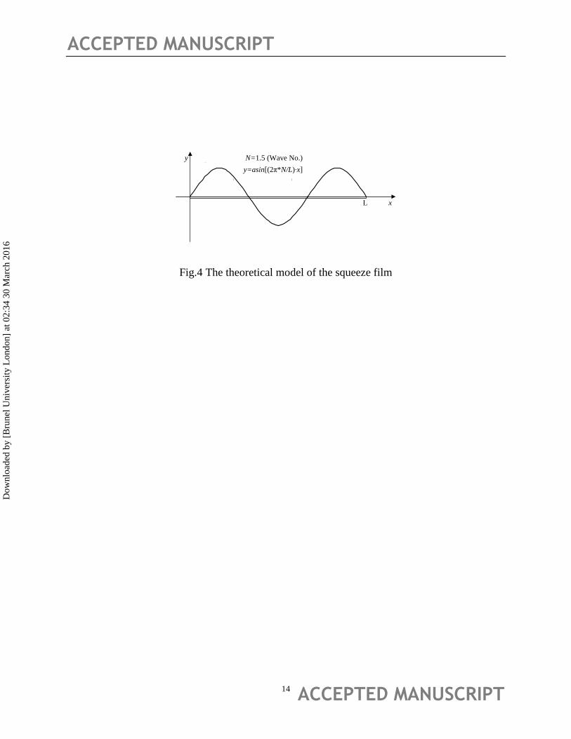
3.2 The squeeze film model of the actuator
The infinite width squeeze film governing equations for fixed floating object consisted of
Reynolds equation and film thickness ones. The film thickness equation should be defined by the
shapes of the plate at a special frequency. Due to the dimension of the exciting plate and the
actual form of the conveyor belt, it is reasonable to calculate with infinite wide mode.
The film thickness equations with pure flexural modes are shown as Fig.4.
Where, N is wave number, which means the number of wavelength in the exciting plate. Y is the
modal shapes equation in order to determine the position of the vibration point.
So, the dimensionless governing equations for the infinite width plate are listed as follows:
Dow
nloa
ded
by [
Bru
nel U
nive
rsity
Lon
don]
at 0
2:34
30
Mar
ch 2
016
ACCEPTED MANUSCRIPT
ACCEPTED MANUSCRIPT 6
The dimensionless film thickness equation:
TXYTXH sin)(1),( ………………………………………..1
And the Reynolds equation:
T
PHσ
X
PPH
X3
………………………………………………………2
Where, the dimensionless parameters , 1)(0,L
xX ,
ap
pP ,T=ωt,
aph
b20
212
(squeeze number), Y(X)=a∙sin(2πN∙X)/h0
For the square sample, the bearing force can be derived by the pressure integral, as follows
a b
a
S
a dxdyppdxdyppTf0 0
1 )()()(1
……………………………3
Where, S1is the square integral area; a, b are the length and the width respectively.
For the round sample, the pressure integral can be derived as
rdrdpprdrdppTfR
a
S
a 0
2
0
2
02 )()()( …………………………..………………4
Where, S2 is the round integral area; R0 is the radial of the sample; x=rcosθ, y=rsinθ.
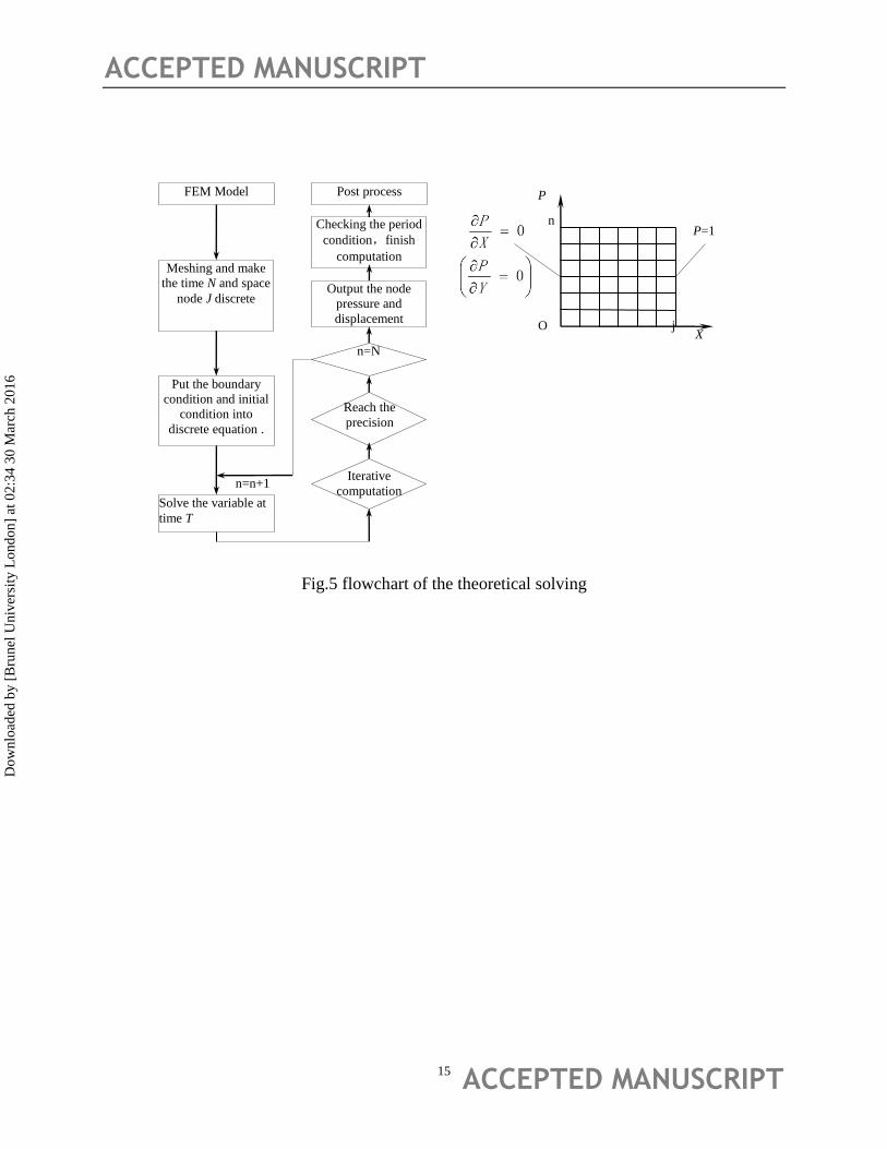
The program flow chart is shown as Fig.5. The Reynolds equation was calculated by the means
of centre difference and coupled with the film thickness equation including the plate deformation.
4 Results and discussion
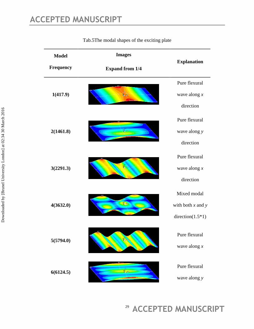
The modal shapes calculated by ANSYS are listed in Tab.5 (below 15 kHz). The Symmetry
model can explain the basic forms for the exciting plate. There are three kinds of modal shapes.
0h
hH
Dow
nloa
ded
by [
Bru
nel U
nive
rsity
Lon
don]
at 0
2:34
30
Mar
ch 2
016
ACCEPTED MANUSCRIPT
ACCEPTED MANUSCRIPT 7
First, they are the pure flexural mode along X direction such as Mode 1st, 3rd, 5th and so on.
Second, they are the pure flexural modes along Y direction such as 2nd, 6th, 12th, and so on. The
last are mixed wave shapes with different wave number along X and Y direction. For example,
the fourth step of modal shapes show the 1.5*1 mixed wave shapes.
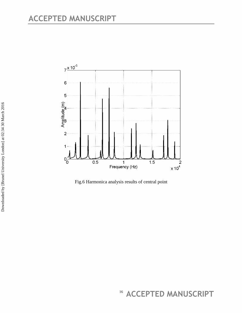
For the convey belt, the larger amplitude in the central line of the plate are needed. The forced
harmonica spectrum on origin point (central point) is shown as Fig. 6. Not all of the modes can
be stimulated well in the forced vibrating condition and also, not all of the peaks of vibrating
amplitude are the natural modes, but some are the harmonica modes. The amplitude-frequency
curves showed the magnitude trend with the increase of the frequency. Nearly all the modal
shapes can be excited, but with different magnitude. The harmonica results are corresponding
with the modal shapes. But the resonant frequency is different a little due to the coupling effect
of piezo-electric materials.
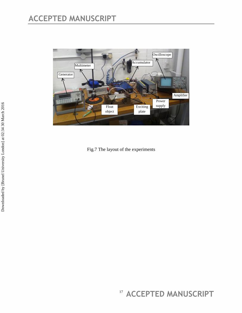
5 Experiments and verification
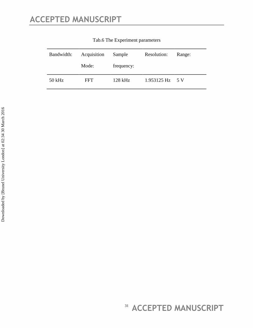
The experiments instruments are shown in Fig.7, including signal generator, power supply
amplifier, oscilloscope, accumulator and millimetre. Some key parameters in the experiments are
listed in Tab.6.
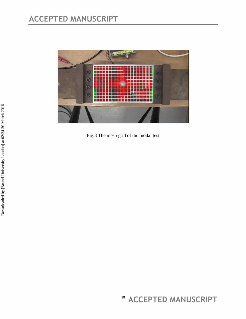
The harmonica shapes of the plate are test by the laser scanning vibrometer from Polytec
Company. 41x25 total 1025 nodes are distributed on the plate to collect the velocity on Z (height)
direction as Fig.8. The sweeping voltage is 5V.
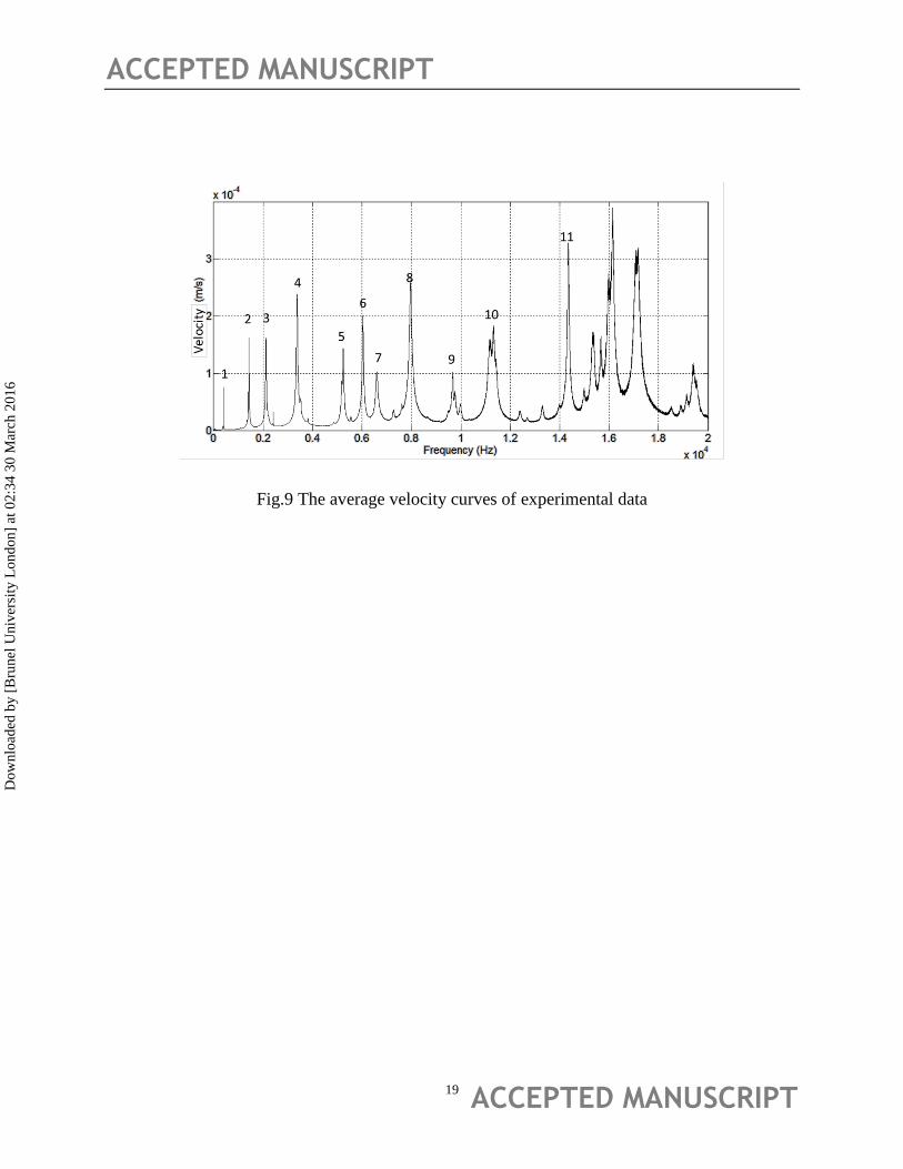
The average velocity RMS on all surface nodes curves versus frequency is shown as Fig.9.Due
to the symmetry mode in ANSYS, some of the harmonic resonance of the plate could be missing.
Dow
nloa
ded
by [
Bru
nel U
nive
rsity
Lon
don]
at 0
2:34
30
Mar
ch 2
016
ACCEPTED MANUSCRIPT
ACCEPTED MANUSCRIPT 8
But the mainly levitation point and modal shapes were shown in the spectrum. By contrast to the
experiments harmonica spectrum, we found that there are more irregular peaks in the
experiments results due to the symmetry model in the theoretical analysis. The same, we extract
the harmonica shapes below 15KHz frequency from the experiments. There corresponding plate
deformations are listed in Tab.7.
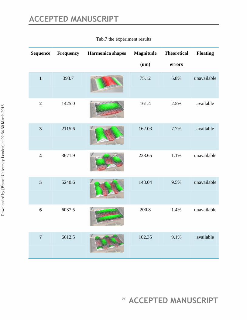
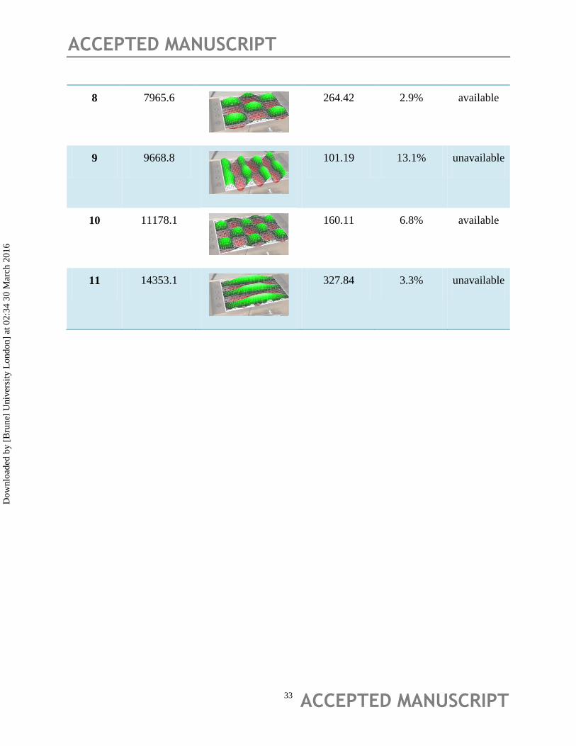
By contrast to the simulation results in Tab.5, from Tab.7, we found that the symmetry model
can better embody the modal shape of the plates. All of the shapes of peaks are included in the
Tab.5 (theoretical one) when the frequency is below 15 kHz. The theoretical errors showed that
all the simulation results of one fourth model against the experiments results are below 15%. The
largest errors occurred at the ones along X direction (step 3, 5, 9) due to the simplified boundary
condition. In opposite, the ones along Y direction have best accuracy due to the free boundaries.
The experiment results showed that not all of the modal shapes can make the object self-levitated.
The pure ones are appropriate for lower frequency while the mixed ones are appropriate for
higher frequency. This phenomenon can explain that some researchers gave the different
optimization modal shapes for the self-levitation of different structures and this result gave a
significant guidance to the prototype design.
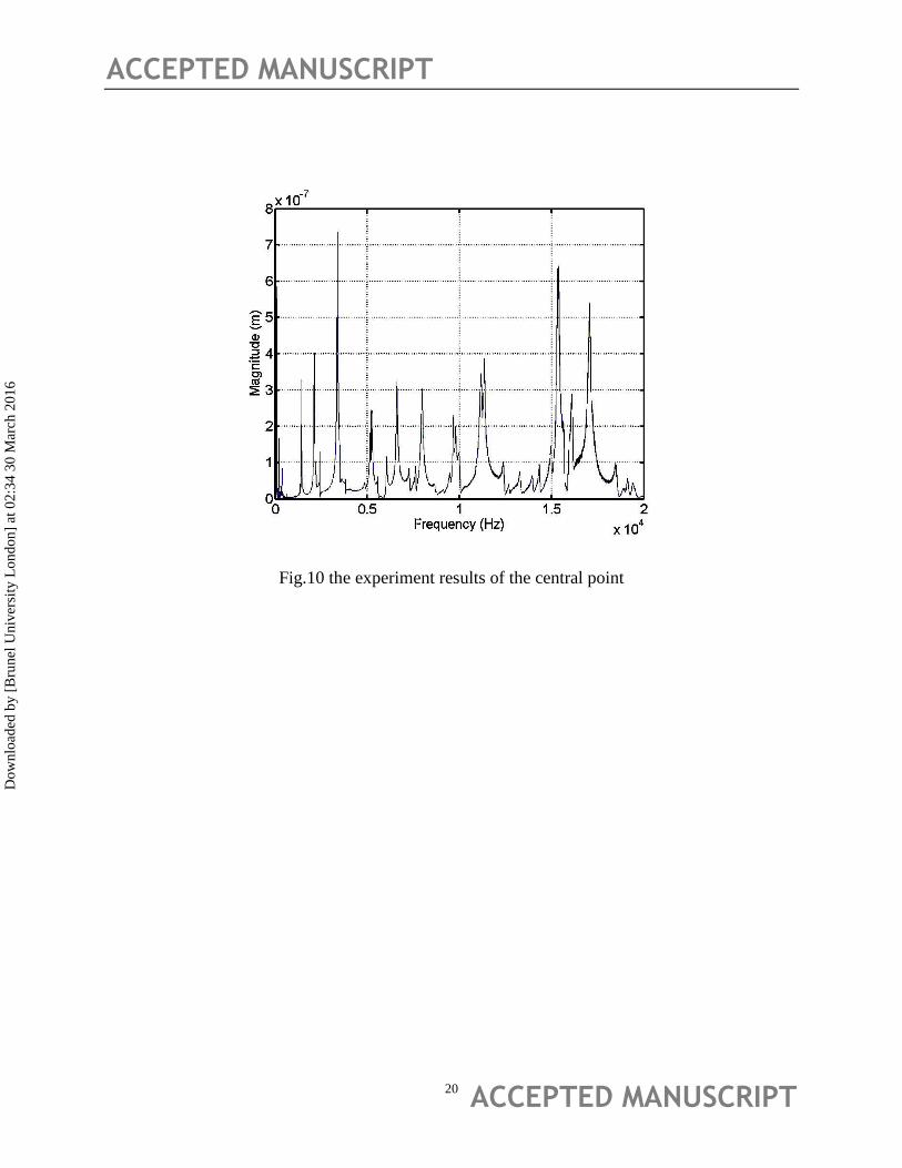
The displace results of the central point are shown in Fig.10. It is different with the RMS curves
but have a same trend with it. By contrast with the harmonica simulation results (Fig.6), the
results implied that the amplitude in the central point embodied the whole vibrating status to a
certain extent.
Dow
nloa
ded
by [
Bru
nel U
nive
rsity
Lon
don]
at 0
2:34
30
Mar
ch 2
016
ACCEPTED MANUSCRIPT
ACCEPTED MANUSCRIPT 9
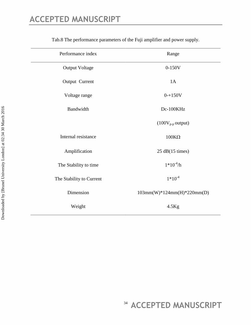
The levitation experiment needs the amplifier to enlarge the energy input. The performance
parameters of Fuji amplifier are listed as Tab.8. It can provide the fixed 15 times magnifying for
all the D.C and A.C signal. It also can adjust the work point for obtaining the largest band for the
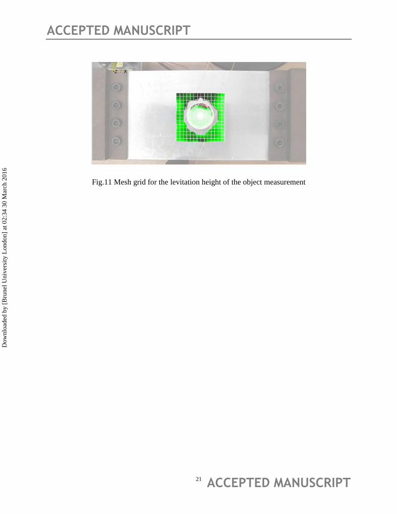
experiments. The levitation height of the object was tested by the laser scanning sensor (in
Fig.11). The levitation object is made of nylon, the dimension is Ф25mm X 3mm and the weight
is 6g. For the largest energy output, the work point should be defined in the amplifier. The 7 volt
offset (before amplify) can guarantee the largest amplitude and clipping does not appear in which,
the oscilloscope can pride significant help in the experiments setup.
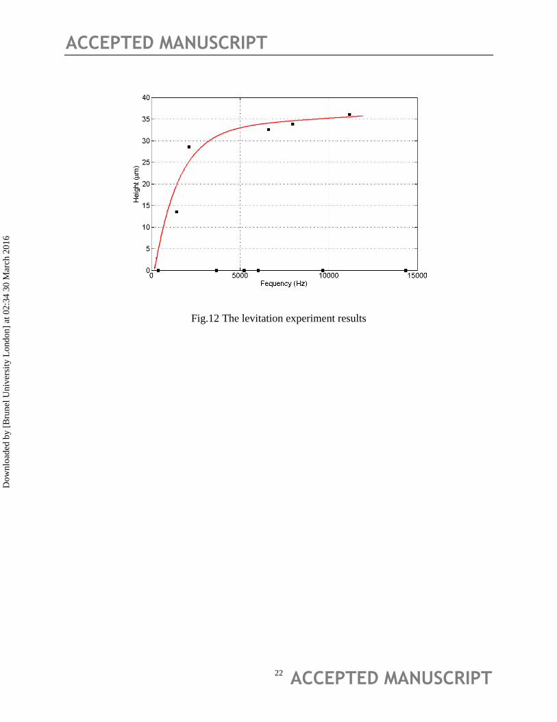
The experiment results and fitting curves are shown as Fig.12. All the experiment points are
corresponding to the modal results in Tab.7 (Black Square). The results implied that the
levitation can be achieved in 6 points in the frequency band, and other points are failed to levitate.
The failed experiment points showed that the pure flexible wave is appropriate to achieve
levitation in low frequency. In opposite, the mixed shapes are appropriate in higher frequency.
This principle can guide and optimize the design of NFAL platform which work in different
frequency band.
The fitting curve expression is an exponential function with 95% confidence bounds:
F(x)=32.2*exp(8.416e-6*x) -44.86*exp(-7.764e-4*x)……………………….…….4
This expression can give the estimate levitation height of the object, the trend of the levitation
curve is reasonable and corresponding to the theoretical results [7],[20]
Dow
nloa
ded
by [
Bru
nel U
nive
rsity
Lon
don]
at 0
2:34
30
Mar
ch 2
016
ACCEPTED MANUSCRIPT
ACCEPTED MANUSCRIPT 10
6 Conclusion
1) The plate actuator with four piezo-electric discs has considerable bearing force that it
can be used in the can conveyor Belt.
2) Almost all of harmonica shapes can be expressed in the simulation of the one fourth
models. The symmetry shapes have larger bearing force and the levitated object is more
stable.
3) The mode design is determined by the range of work band, for the lower band, pure
flexural modes are appropriate. In opposite, the mixed modes are benefit in higher
frequency range.
4) For acquiring more energy from the amplifier, the working point should be set up to
guarantee the largest amplitude and clipping did not appear.
5) The levitation height is an exponential function of frequency. It is consistent to the
theoretical results
Dow
nloa
ded
by [
Bru
nel U
nive
rsity
Lon
don]
at 0
2:34
30
Mar
ch 2
016
ACCEPTED MANUSCRIPT
ACCEPTED MANUSCRIPT 11
Fig.1 The designed plate actuator
Real Length 200 mm
The effective Length 160 mm
Dow
nloa
ded
by [
Bru
nel U
nive
rsity
Lon
don]
at 0
2:34
30
Mar
ch 2
016
ACCEPTED MANUSCRIPT
ACCEPTED MANUSCRIPT 12
2
2.2
2.5
160
10
0
Ø60
view
4xØ274xØ20
Unit: mm
Fig.2 Dimension of the exciting plate
Dow
nloa
ded
by [
Bru
nel U
nive
rsity
Lon
don]
at 0
2:34
30
Mar
ch 2
016
ACCEPTED MANUSCRIPT
ACCEPTED MANUSCRIPT 13
Fig.3 The levitation samples.
Dow
nloa
ded
by [
Bru
nel U
nive
rsity
Lon
don]
at 0
2:34
30
Mar
ch 2
016
ACCEPTED MANUSCRIPT
ACCEPTED MANUSCRIPT 14
L
N=1.5 (Wave No.)
y=asin[(2π*N/L)∙x]
x
y
Fig.4 The theoretical model of the squeeze film
Dow
nloa
ded
by [
Bru
nel U
nive
rsity
Lon
don]
at 0
2:34
30
Mar
ch 2
016
ACCEPTED MANUSCRIPT
ACCEPTED MANUSCRIPT 15
Fig.5 flowchart of the theoretical solving
FEM Model
Meshing and make
the time N and space
node J discrete
Put the boundary
condition and initial
condition into
discrete equation .
Solve the variable at
time T
n=N
n=n+1
Output the node
pressure and
displacement
Checking the period
condition,finish
computation
Reach the
precision
Iterative
computation
Post process P
X O j
n
P=1
Dow
nloa
ded
by [
Bru
nel U
nive
rsity
Lon
don]
at 0
2:34
30
Mar
ch 2
016
ACCEPTED MANUSCRIPT
ACCEPTED MANUSCRIPT 16
Fig.6 Harmonica analysis results of central point
Dow
nloa
ded
by [
Bru
nel U
nive
rsity
Lon
don]
at 0
2:34
30
Mar
ch 2
016
ACCEPTED MANUSCRIPT
ACCEPTED MANUSCRIPT 17
Fig.7 The layout of the experiments
Generator
Multimeter
Float
object
Exciting
plate
Accumulator
Oscilloscope
Power
supply
Amplifier
Dow
nloa
ded
by [
Bru
nel U
nive
rsity
Lon
don]
at 0
2:34
30
Mar
ch 2
016
ACCEPTED MANUSCRIPT
ACCEPTED MANUSCRIPT 18
Fig.8 The mesh grid of the modal test
Dow
nloa
ded
by [
Bru
nel U
nive
rsity
Lon
don]
at 0
2:34
30
Mar
ch 2
016
ACCEPTED MANUSCRIPT
ACCEPTED MANUSCRIPT 19
Fig.9 The average velocity curves of experimental data
Dow
nloa
ded
by [
Bru
nel U
nive
rsity
Lon
don]
at 0
2:34
30
Mar
ch 2
016
ACCEPTED MANUSCRIPT
ACCEPTED MANUSCRIPT 20
Fig.10 the experiment results of the central point
Dow
nloa
ded
by [
Bru
nel U
nive
rsity
Lon
don]
at 0
2:34
30
Mar
ch 2
016
ACCEPTED MANUSCRIPT
ACCEPTED MANUSCRIPT 21
Fig.11 Mesh grid for the levitation height of the object measurement
Dow
nloa
ded
by [
Bru
nel U
nive
rsity
Lon
don]
at 0
2:34
30
Mar
ch 2
016
ACCEPTED MANUSCRIPT
ACCEPTED MANUSCRIPT 22
Fig.12 The levitation experiment results
Dow
nloa
ded
by [
Bru
nel U
nive
rsity
Lon
don]
at 0
2:34
30
Mar
ch 2
016
ACCEPTED MANUSCRIPT
ACCEPTED MANUSCRIPT 23
Tab.1 The research history of the NFAL
Publication
Time
First Author Model Type
Modal Shape
of Excitation
Disk
Sample
suspended
situation
Calculation method
1961 Langlois2
Infinite
Wide
Axial
Symmetry
Not take
account
Fixed
Reynolds equation
perturbation
1964 Sablu3
Axial
Symmetry
Not take
account
Fixed
Reynolds equation
numerical method
1968 Diprima21
Infinite
Wide
Not take
account
Fixed
Reynolds equation
analytic method
1969 Beck4
Axial
Symmetry
Not take
account
Free
Reynolds equation and
motion equation
perturbation method
1983 Takada22
Infinite
Wide
Not take
account
Fixed
Reynolds equation
linearization method
1984
Shigeaki.Kuroda
23
Axial
Symmetry
Not take
account
Free Numerical method
Dow
nloa
ded
by [
Bru
nel U
nive
rsity
Lon
don]
at 0
2:34
30
Mar
ch 2
016
ACCEPTED MANUSCRIPT
ACCEPTED MANUSCRIPT 24
1996
Yoshiki .Hashim
oto7
Infinite
Wide
Flexible
modal shape
Fixed
Ultrasonic analytical
theory
1997 Beltman24
2D
Rectangle
Not take
account
Fixed Finite element method
2003 Butcher25
Axial
Symmetry
Flexible
modal shape
Fixed Numerical method
2004 Minikes8
Infinite
Wide
Rigid and
Flexible
model
Fixed
Modified Reynolds
linearization method
2006 Stolarski9 2D Model
Not take
account
Fixed
Reynolds equation
numerical method
2006 Stolarski26
2D Model
Flextrual
model
Fixed Experiment reserch
2007
Shigeka.Yoshim
oto27
2D Model Take account Free
Reynolds equation
numerical method
ANSYS fluid simulation
2009 LIU Pinkuan11
Axial
Symmetry
Flexible
Wave
Fixed
Reynolds equation
numerical method
2010 Stolarski10
2D Model Take account Free
Reynolds equation
numerical method
Dow
nloa
ded
by [
Bru
nel U
nive
rsity
Lon
don]
at 0
2:34
30
Mar
ch 2
016
ACCEPTED MANUSCRIPT
ACCEPTED MANUSCRIPT 25
ANSYS fluid simulation
2011 WEI Bin28
Axial
Symmetry
Real modal
shape
Fixed
ANSYS ultrasonic
simulation
2012 Stolarski29
2D Model take account Fixed
Reynolds equation
numerical method
2014 WEI Bin20
Axial
Symmetry
Mixed modal
shape
Free
Reynolds equation
analytic and numerical
method
2014 WEI Bin30
Infinite wide Rigid model Fixed
Reynolds equation
linearization method
Dow
nloa
ded
by [
Bru
nel U
nive
rsity
Lon
don]
at 0
2:34
30
Mar
ch 2
016
ACCEPTED MANUSCRIPT
ACCEPTED MANUSCRIPT 26
Tab.2 The dimension and the materials of the piezo-electric discs and the plate
Sort image Drawing Properties
Piezo-
electric
disc
Materials: Brass and
iron
Resonant frequency:
4.2K
D:27mm
d: 20mm
t=0.3
T=0.5
Plate and
layout
As Fig.2
Materials: Aluminium
Real length:200mm
Effective lenth:160mm
Width:100mm
Height:2mm
Dow
nloa
ded
by [
Bru
nel U
nive
rsity
Lon
don]
at 0
2:34
30
Mar
ch 2
016
ACCEPTED MANUSCRIPT
ACCEPTED MANUSCRIPT 27
Tab.3 The Finite model and boundary condition of the exciting plate
Geometry and materials Hexahedral mesh and
element (1/4)
Boundary condition and Load
(1/4)
4xPZT4
Aluminium
Brass Solid45 Element
Solid226
ElementeeeeeEEle
Fixed boundaries
Voltage Load
Symmetry boundaries with Surface YZ
Symmetry boundaries
with Surface XZ
Dow
nloa
ded
by [
Bru
nel U
nive
rsity
Lon
don]
at 0
2:34
30
Mar
ch 2
016
ACCEPTED MANUSCRIPT
ACCEPTED MANUSCRIPT 28
Tab.4 The materials of the elements.
Materials
Dielectric
constants
Young’s
Modulus
(GPa)
Poisson
's ratio
Density
(kg/m3)
Piezoelectric
voltage
constants
(C/m2)
Aluminiu
m
/ 69 0.3 2700 /
Brass / 110 0.3 6400 /
PZT4 [
]
[ ]
/ 7500
[ ]
Dow
nloa
ded
by [
Bru
nel U
nive
rsity
Lon
don]
at 0
2:34
30
Mar
ch 2
016
ACCEPTED MANUSCRIPT
ACCEPTED MANUSCRIPT 29
Tab.5The modal shapes of the exciting plate
Model
Frequency
Images
Expand from 1/4
Explanation
1(417.9)
Pure flexural
wave along x
direction
2(1461.8)
Pure flexural
wave along y
direction
3(2291.3)
Pure flexural
wave along x
direction
4(3632.0)
Mixed modal
with both x and y
direction(1.5*1)
5(5794.0)
Pure flexural
wave along x
6(6124.5)
Pure flexural
wave along y
Dow
nloa
ded
by [
Bru
nel U
nive
rsity
Lon
don]
at 0
2:34
30
Mar
ch 2
016
ACCEPTED MANUSCRIPT
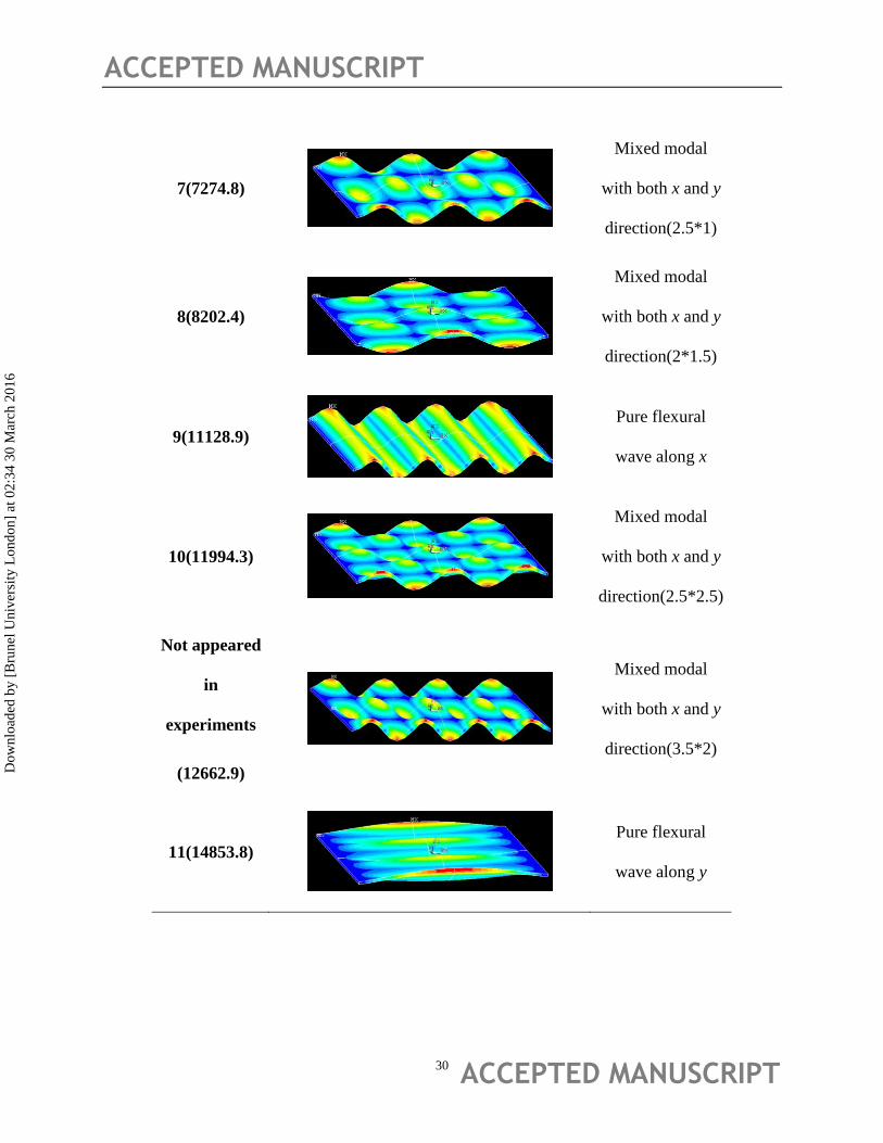
ACCEPTED MANUSCRIPT 30
7(7274.8)
Mixed modal
with both x and y
direction(2.5*1)
8(8202.4)
Mixed modal
with both x and y
direction(2*1.5)
9(11128.9)
Pure flexural
wave along x
10(11994.3)
Mixed modal
with both x and y
direction(2.5*2.5)
Not appeared
in
experiments
(12662.9)
Mixed modal
with both x and y
direction(3.5*2)
11(14853.8)
Pure flexural
wave along y
Dow
nloa
ded
by [
Bru
nel U
nive
rsity
Lon
don]
at 0
2:34
30
Mar
ch 2
016
ACCEPTED MANUSCRIPT
ACCEPTED MANUSCRIPT 31
Tab.6 The Experiment parameters
Bandwidth: Acquisition
Mode:
Sample
frequency:
Resolution: Range:
50 kHz FFT 128 kHz 1.953125 Hz 5 V
Dow
nloa
ded
by [
Bru
nel U
nive
rsity
Lon
don]
at 0
2:34
30
Mar
ch 2
016
ACCEPTED MANUSCRIPT
ACCEPTED MANUSCRIPT 32
Tab.7 the experiment results
Sequence Frequency Harmonica shapes Magnitude
(um)
Theoretical
errors
Floating
1 393.7
75.12 5.8% unavailable
2 1425.0
161.4 2.5% available
3 2115.6
162.03 7.7% available
4 3671.9
238.65 1.1% unavailable
5 5240.6
143.04 9.5% unavailable
6 6037.5
200.8 1.4% unavailable
7 6612.5
102.35 9.1% available
Dow
nloa
ded
by [
Bru
nel U
nive
rsity
Lon
don]
at 0
2:34
30
Mar
ch 2
016
ACCEPTED MANUSCRIPT
ACCEPTED MANUSCRIPT 33
8 7965.6
264.42 2.9% available
9 9668.8
101.19 13.1% unavailable
10 11178.1
160.11 6.8% available
11 14353.1
327.84 3.3% unavailable
Dow
nloa
ded
by [
Bru
nel U
nive
rsity
Lon
don]
at 0
2:34
30
Mar
ch 2
016
ACCEPTED MANUSCRIPT
ACCEPTED MANUSCRIPT 34
Tab.8 The performance parameters of the Fuji amplifier and power supply.
Performance index Range
Output Voltage 0-150V
Output Current 1A
Voltage range 0-+150V
Bandwidth Dc-100KHz
(100Vp-p output)
Internal resistance 100K
Amplification 25 dB(15 times)
The Stability to time 1*10-4
/h
The Stability to Current 1*10-4
Dimension 103mm(W)*124mm(H)*220mm(D)
Weight 4.5Kg
Dow
nloa
ded
by [
Bru
nel U
nive
rsity
Lon
don]
at 0
2:34
30
Mar
ch 2
016
ACCEPTED MANUSCRIPT
ACCEPTED MANUSCRIPT 35
Reference
[1]Gross.W.A (1962). .Gas Film Lubrication, New York :Wiley.
[2]W.E.Langlois (1962). Isothermal Squeeze Films, Quarterly of Applied Mathematics. 1962.XX(2), pp
131-150
[3]Salbu EOJ (1964). Compressible squeeze films and squeeze bearings ASME J of Basic Eng, 86(3), pp
355-366
[4]Beck JV (1969). Experimental and analysis of a flat disk squeeze-film bearing including effects of
supported mass motion,Holiday WG. ,Strodtman CL. ASME J of Lubr,91(1), pp 138-148
[5]Shigeaki.Kuroda,Noriyuki.Hirata (1984). Near field acoustic levitation of planar specimens using
flexural vibration. J of Lubr. 50 (459), pp 2727-2731.
[6]M.Q JING, H LIU, Y SHEN, L YU (2008).Journal of Xi'an Jiaotong University, New Style Squeeze
Film Air Bearing. 42(07), pp 799-802
[7]Yoshiki Hashimoto (1996). Near field acoustic levitation of planar specimens using flexural vibration.
J.Acoust.Soc. 100(4), pp 2057-2061
[8]Adi Minikes,I Bucher (2004). Levitation force induced by pressure radiation in gas squeeze films.
J.Acoust.Soc, 116(1), pp 217-226
[9]T.A. Stolarski, Wei Chai (2006). Load-carrying capacity generation in squeeze film action.
International Journal of Mechanical Sciences. 48(7), pp 736–741
[10]T.A Stolarski (2010). Numerical modelling and experimental verification of compressible squeeze
film pressure. Tribology international. 43(1), pp 356-360
[11]Pinkuan Liu, Jin Li, Han Ding (2009). Modeling and experimental study on Near-Field Acoustic
Levitation by flexural mode, IEEE Trans. Ultrason. Ferroelectr. Freq.Control. 56(12), pp 2679-2685
[12]Jin Li, Pinkuan Liu, Han Ding, Wenwu Cao (2011). Modeling characterization and optimization
design for PZT transducer used in Near Field Acoustic Levitation. Sensors and Actuators A. 171(2), pp
260–265
[13]WEI Bin, MA Xizhi (2010).Research on the Characteristic of the Floating Guide Way with Squeeze
Film. LUBRICATION ENGINEERING, 35(8), pp 54-58
[14]WEI Bin, MA Xizhi(2010).Research on the Characteristics of Squeeze Film Floating Guide Way
Including the Model Effect. LUBRICATION ENGINEERING, 35(2), pp 33-35
[15]Jin Li, Wenwu Cao, Pinkuan Liu, and Han Ding(2010). Influence of gas inertia and edge effect on
squeeze film in near field acoustic levitation. Appl. Phys. Lett. 96(24), 243507 pp 1-8
[16]W. J Xie, B. Wei (2012). Parametric study of single-axis acoustic levitation. Appl. Phys. Lett. 79(4),
pp 881-886
[17]Mohamed Nabhani, Mohamed El Khlifi & Benyebka. Combined Non-Newtonian and Viscous Shear
Effects on Porous Squeeze Film Behavior. Trabology Transactions. 55(4), pp 491-502
Dow
nloa
ded
by [
Bru
nel U
nive
rsity
Lon
don]
at 0
2:34
30
Mar
ch 2
016
ACCEPTED MANUSCRIPT
ACCEPTED MANUSCRIPT 36
[18]T. V. V. L. N. Rao, A. M. A. Rani and T. Nagarajan etc(2013). Analysis of Journal Bearing with
Double-Layer Porous Lubricant Film: Influence of Surface Porous Layer Configuration. Tribology
Transactions. 56(5), pp 841-847
[19]A. Bouzidane & M. Thomas (2013). Nonlinear Dynamic Analysis of a Rigid Rotor Supported by a
Three-Pad Hydrostatic Squeeze Film Dampers. Tribology Transactions. 56(5), pp 717-727
[20]YZ WANG, Bin WEI (2013). Mixed-modal Disk Gas Squeeze Film Theoretical and Experimental
Analysis. International Journal of Modern Physics. 27(25), 1350168,pp 1-20
[21]R.C. Diprima, Asymptotic (1968). Methods for an Infinitely Long Slider Squeeze-film Bearing. J.
Tribol. 90(1), pp 173-183
[22]H.Takada H.Miura (1983). Characteristics of Squeeze Air film Between Nonparallel Plates. ASME,J
of Lubr.Technol 105(1), pp 147-151.
[23]Shigeaki.Kuroda,Noriyuki.Hirata (1984). The Characteristic of Motion of a round plate Supported on
Squeeze Air Film.JSME, J of Lubr.,50(459), pp 2727-2731
[24]W.M.Beltman,P.J.M.Vander Hoogt(1997), J. Sound and Vibration, 206(2), pp 217-241
[25]A.Minikes, I.Bucher (2003). Coupled dynamics of a squeeze-film levitated mass and a vibrating
piezoelectric disc: numerical analysis and experimental study. Journal of Sound and Vibration. 263(2),
pp 241-268
[26]Ha, DN; Stolarski, TA; Yoshimoto,S (2005). An aerodynamic bearing with adjustable geometry and
self-lifting capacity. Part 1: self-lift capacity by squeeze film. PROCEEDINGS OF THE INSTITUTION
OF MECHANICAL ENGINEERS PART J-JOURNAL OF ENGINEERING TRIBOLOGY, 219(J1), pp
33-39
[27]Shigeka Yoshimoto,Hiroyuki Kobayashi,Masaaki Miyatake (2007), A non-contact chuck using
ultrasonic vibration: analysis of the primary cause of the holding force acting on a floating object.
Tribology International. 40(3), pp 503-511
[28]WEI Bin, MA Xizhi, TANG Weikun (2011), Study on Characteristics of Ultrasonic Levitation with
Piezo-ceramics Exciting. PIEZOELECTRICS ACOUSTOOPTICS. 33(1), pp 71-78
[29]Stolarski, TA., Xue, Y. and Yoshimoto, S (2011)., Air journal bearing utilizing near-field acoustic
levitation stationary shaft case. PROCEEDINGS OF THE INSTITUTION OF MECHANICAL
ENGINEERS PART J-JOURNAL OF ENGINEERING TRIBOLOG . 225(3),:pp 120- 127
[30]YZ WANG, Bin WEI (2013). A Linear Solution for Gas Squeeze Film Characteristics in Ultrasonic
Excitation Condition The journal of the Chinese society of mechanical engineers. 2013,34(5), pp 469-473
Dow
nloa
ded
by [
Bru
nel U
nive
rsity
Lon
don]
at 0
2:34
30
Mar
ch 2
016
ACCEPTED MANUSCRIPT
ACCEPTED MANUSCRIPT 37
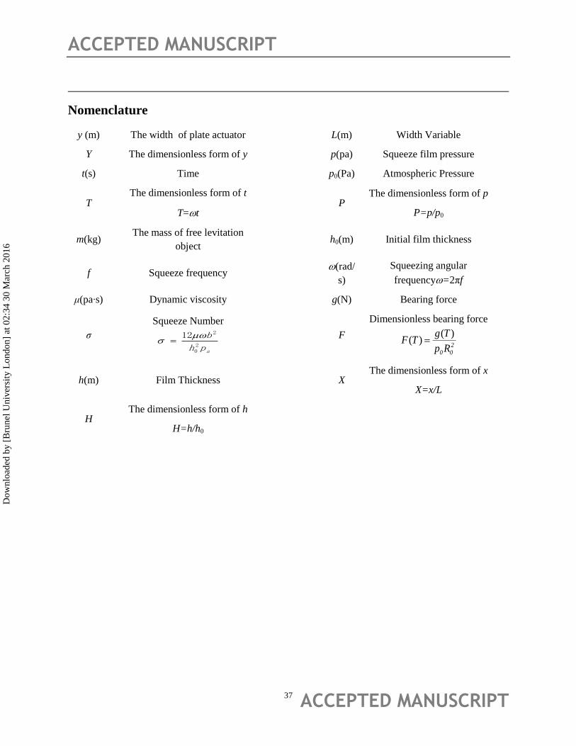
Nomenclature
y (m) The width of plate actuator L(m) Width Variable
Y The dimensionless form of y p(pa) Squeeze film pressure
t(s) Time p0(Pa) Atmospheric Pressure
T The dimensionless form of t
T=t
P
The dimensionless form of p
P=p/p0
m(kg) The mass of free levitation
object
h0(m) Initial film thickness
f Squeeze frequency (rad/
s)
Squeezing angular
frequency=2πf
μ(pa∙s) Dynamic viscosity g(N) Bearing force
σ
Squeeze Number
aph
b20
212
F
Dimensionless bearing force
2
00 Rp
TgTF
)()(
h(m) Film Thickness
X The dimensionless form of x
X=x/L
H The dimensionless form of h
H=h/h0
Dow
nloa
ded
by [
Bru
nel U
nive
rsity
Lon
don]
at 0
2:34
30
Mar
ch 2
016
ACCEPTED MANUSCRIPT
ACCEPTED MANUSCRIPT 38
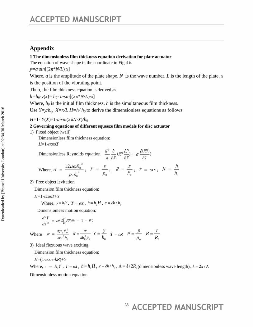
Appendix
1 The dimensionless film thickness equation derivation for plate actuator
The equation of wave shape in the coordinate in Fig.4 is
y=a·sin[(2π*N/L)∙x]
Where, a is the amplitude of the plate shape, N is the wave number, L is the length of the plate, x
is the position of the vibrating point.
Then, the film thickness equation is derived as
h=h0-y(x)= h0- a·sin[(2π*N/L)∙x]
Where, h0 is the initial film thickness, h is the simultaneous film thickness.
Use Y=y/h0, X=x/L H=h/ h0 to derive the dimensionless equations as follows
H=1- Y(X)=1-a∙sin(2πN∙X)/h0
2 Governing equations of different squeeze film models for disc actuator
1) Fixed object (wall)
Dimensionless film thickness equation:
H=1-εcosT
Dimensionless Reynolds equation ))(
)(T
PH
R
PRP
RR
H 3
Where, 2
00
2
012
hp
R ;
0p
pP ;
0R
rR ; tT ;
0h
hH
2) Free object levitation
Dimension film thickness equation:
H=1-εcosT+Y
Where, Yhy 0 , tT , Hhh 0 , 0/ hh
Dimensionless motion equation:
)12(1
02
2
WPRdRdT
Yd
Where,0
2
20
hm
Rp a
apR
wW
2
0
0h
yY tT
ap
pP
0R
rR
3) Ideal flexuous wave exciting
Dimension film thickness equation:
H=(1-εcos-kR)+Y
Where, Yhy 0 , tT , Hhh 0 , 0/ hh , 02/ R (dimensionless wave length), /2k
Dimensionless motion equation
Dow
nloa
ded
by [
Bru
nel U
nive
rsity
Lon
don]
at 0
2:34
30
Mar
ch 2
016
ACCEPTED MANUSCRIPT
ACCEPTED MANUSCRIPT 39
)12(1
02
2
WPRdRdT
Yd
Where, 0
2
2
0
hm
Rpa
,
apR
wW
20
, 0h
yY , tT ,
ap
pP ,
0R
rR
Dimensionless Reynolds equation T
PH
R
PRPH
RR
)()(
1 3
Dow
nloa
ded
by [
Bru
nel U
nive
rsity
Lon
don]
at 0
2:34
30
Mar
ch 2
016


![1 SERIES Belt Conveyor System B090 - Bett Sistemi Srl€¦ · CONVEYOR BELT DEVELOPMENT CALCULATION FORMULA Conveyor belt length = 300 + {[(L-94)-(2• Conveyor belt thick. )]•2}](https://img.pdfslide.us/doc/110x75/5ad3c4047f8b9a48398b7ae4/1-series-belt-conveyor-system-b090-bett-sistemi-conveyor-belt-development-calculation.jpg)