Embed Size (px)
Citation preview
Self Healing of Concrete Structures - Novel approach usingporous network concreteSangadji Senot, Erik SchlangenJournal of Advanced Concrete Technology, volume ( ), pp.10 2012 185-194
Self-healing capability of fiber reinforced cementitious compositesDaisuke Homma, Hirozo Mihashi Tomoya Nishiwaki,Journal of Advanced Concrete Technology, volume ( ), pp.7 2009 217-228
Crack Self-healing Behavior of Cementitious Composites incorporating Various Mineral AdmixturesTae-Ho Ahn , Toshiharu KishiJournal of Advanced Concrete Technology, volume ( ), pp.8 2010 171-186
Experimental Study on Self-Healing Capability of FRCC Using Different Types of Synthetic FibersTomoya Nishiwaki, Marina Koda Hirozo Mihashi, , Takatsune KikutaJournal of Advanced Concrete Technology, volume ( ), pp.10 2012 195-206
Development of Engineered Self-Healing and Self-Repairing Concrete-State-of-the-Art ReportHirozo Mihashi, Tomoya NishiwakiJournal of Advanced Concrete Technology, volume ( ), pp.10 2012 170-184
Robust Self-Healing Concrete for Sustainable InfrastructureVictor C. Li , Emily HerbertJournal of Advanced Concrete Technology, volume ( ), pp.10 2012 207-218
Makoto Yamada,
Journal of Advanced Concrete Technology Vol. 10, 185-194, May 2012 / Copyright © 2012 Japan Concrete Institute 185
Invited paper
Self Healing of Concrete Structures - Novel Approach Using Porous Network Concrete Senot Sangadji1,2 and Erik Schlangen1
Received 11 March 2012, revised 29 May 2012 doi:10.3151/jact.10.185
Abstract To repair concrete cracks in difficult or dangerous conditions such as underground structures or hazardous liquid con-tainers, self healing mechanism is a promising alternative method. This research aims to imitate the bone self healing process by putting porous concrete internally in the concrete structure to create a porous network similar to ‘spongious bone’. When cracks are formed and detected by sensors, healing agent can be infused into the porous network so as to fill up voids and seal a crack or cracks in the concrete body. This idea was tested using cylindrical and beam samples. A porous concrete core was placed in the concrete specimens. Uniaxial tensile load in the case of the cylindrical samples and bending load in case of beams was applied to create cracks. A healing action was performed by injecting healing agent manually. The results show that a macro-crack is sealed and strength of concrete is regained. Therefore, the con-cept is considered as to be feasible for self repair mechanism in concrete.
1. Introduction
Generally, public has expectations of very long service-live of infrastructures, not only 50 years as in expected design life, but more like ‘last-forever’. However, many constructed infrastructure, e.g. building, concrete struc-ture, transport facilities, built in the second half of the last century is rapidly approaching its critical period marked by reduced functionality due to material deterio-ration. In contrary, exponential urban population growth has caused increasing public demand of infrastructure that serves their need in constant high level of service.
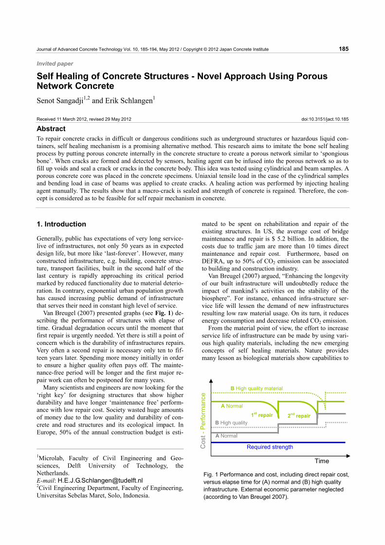
Van Breugel (2007) presented graphs (see Fig. 1) de-scribing the performance of structures with elapse of time. Gradual degradation occurs until the moment that first repair is urgently needed. Yet there is still a point of concern which is the durability of infrastructures repairs. Very often a second repair is necessary only ten to fif-teen years later. Spending more money initially in order to ensure a higher quality often pays off. The mainte-nance-free period will be longer and the first major re-pair work can often be postponed for many years.
Many scientists and engineers are now looking for the ‘right key’ for designing structures that show higher durability and have longer ‘maintenance free’ perform-ance with low repair cost. Society wasted huge amounts of money due to the low quality and durability of con-crete and road structures and its ecological impact. In Europe, 50% of the annual construction budget is esti-
mated to be spent on rehabilitation and repair of the existing structures. In US, the average cost of bridge maintenance and repair is $ 5.2 billion. In addition, the costs due to traffic jam are more than 10 times direct maintenance and repair cost. Furthermore, based on DEFRA, up to 50% of CO2 emission can be associated to building and construction industry.
Van Breugel (2007) argued, “Enhancing the longevity of our built infrastructure will undoubtedly reduce the impact of mankind’s activities on the stability of the biosphere”. For instance, enhanced infra-structure ser-vice life will lessen the demand of new infrastructures resulting low raw material usage. On its turn, it reduces energy consumption and decrease related CO2 emission.
From the material point of view, the effort to increase service life of infrastructure can be made by using vari-ous high quality materials, including the new emerging concepts of self healing materials. Nature provides many lesson as biological materials show capabilities to
1Microlab, Faculty of Civil Engineering and Geo-sciences, Delft University of Technology, the Netherlands. E-mail: [email protected] 2Civil Engineering Department, Faculty of Engineering, Universitas Sebelas Maret, Solo, Indonesia.
Cos
t - P
erfo
rman
ce
Time
Required strength
1st repair 2nd repair
A Normal
B High quality material
A Normal
B High quality
Fig. 1 Performance and cost, including direct repair cost, versus elapse time for (A) normal and (B) high quality infrastructure. External economic parameter neglected (according to Van Breugel 2007).
S. Sangadji and E. Schlangen / Journal of Advanced Concrete Technology Vol. 10, 185-194, 2012 186
heal it self by neutralize wound or injury to reach its previous performance.
Along with the damage management paradigm ob-served in nature as proposed by Van der Zwaag (2007), many scientists have developed self-healing materials that mimics many of the features of a biological system. Many techniques and methods have been developed according to the intrinsic properties between the various material classes. However, the common feature is all of these self healing materials are able to sense ‘damage’ and self repair, thus, demonstrate ‘continuous renewal’ its performance. This results to longer material life time.
For infrastructure the ideal case would be that no costs for maintenance and repair have to be considered at all because the material is able to repair itself as de-picted in Fig. 2, (Van Breugel, 2007).
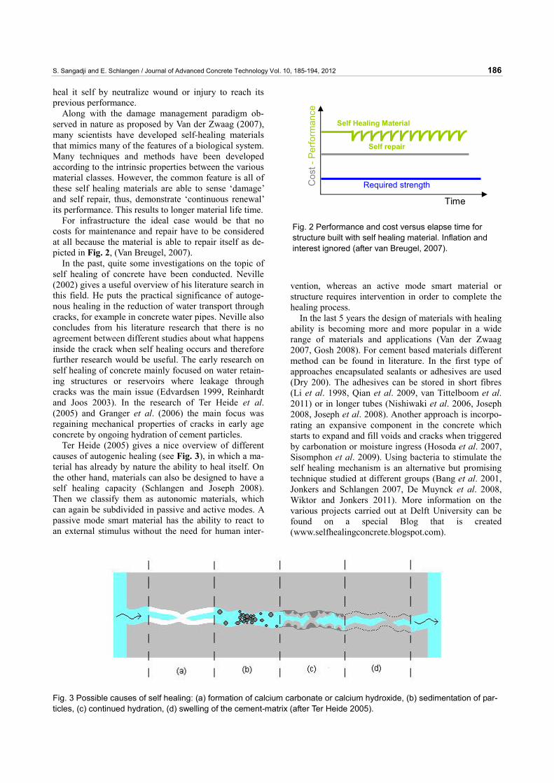
In the past, quite some investigations on the topic of self healing of concrete have been conducted. Neville (2002) gives a useful overview of his literature search in this field. He puts the practical significance of autoge-nous healing in the reduction of water transport through cracks, for example in concrete water pipes. Neville also concludes from his literature research that there is no agreement between different studies about what happens inside the crack when self healing occurs and therefore further research would be useful. The early research on self healing of concrete mainly focused on water retain-ing structures or reservoirs where leakage through cracks was the main issue (Edvardsen 1999, Reinhardt and Joos 2003). In the research of Ter Heide et al. (2005) and Granger et al. (2006) the main focus was regaining mechanical properties of cracks in early age concrete by ongoing hydration of cement particles.
Ter Heide (2005) gives a nice overview of different causes of autogenic healing (see Fig. 3), in which a ma-terial has already by nature the ability to heal itself. On the other hand, materials can also be designed to have a self healing capacity (Schlangen and Joseph 2008). Then we classify them as autonomic materials, which can again be subdivided in passive and active modes. A passive mode smart material has the ability to react to an external stimulus without the need for human inter-
vention, whereas an active mode smart material or structure requires intervention in order to complete the healing process.
In the last 5 years the design of materials with healing ability is becoming more and more popular in a wide range of materials and applications (Van der Zwaag 2007, Gosh 2008). For cement based materials different method can be found in literature. In the first type of approaches encapsulated sealants or adhesives are used (Dry 200). The adhesives can be stored in short fibres (Li et al. 1998, Qian et al. 2009, van Tittelboom et al. 2011) or in longer tubes (Nishiwaki et al. 2006, Joseph 2008, Joseph et al. 2008). Another approach is incorpo-rating an expansive component in the concrete which starts to expand and fill voids and cracks when triggered by carbonation or moisture ingress (Hosoda et al. 2007, Sisomphon et al. 2009). Using bacteria to stimulate the self healing mechanism is an alternative but promising technique studied at different groups (Bang et al. 2001, Jonkers and Schlangen 2007, De Muynck et al. 2008, Wiktor and Jonkers 2011). More information on the various projects carried out at Delft University can be found on a special Blog that is created (www.selfhealingconcrete.blogspot.com).
Fig. 2 Performance and cost versus elapse time for structure built with self healing material. Inflation and interest ignored (after van Breugel, 2007).
Cos
t - P
erfo
rman
ce
Time
Required strength
Self repair
Self Healing Material
Fig. 3 Possible causes of self healing: (a) formation of calcium carbonate or calcium hydroxide, (b) sedimentation of par-ticles, (c) continued hydration, (d) swelling of the cement-matrix (after Ter Heide 2005).
S. Sangadji and E. Schlangen / Journal of Advanced Concrete Technology Vol. 10, 185-194, 2012 187
At the Microlab of Delft University one of the pro-posed ideas is to mimic nature by making a novel po-rous network system in concrete in the form of the spongy part of the bones. This system uses prefabricated thin porous concrete cores which are placed internally in the concrete structure. In the later stage (epoxy-based) healing agents can be transferred through the intercon-nected pores to reach the damage zone, including micro and macro-cracks, and glue the cracks surface together. Alternatively the healing agent could also be a bacteria-containing cement paste (Jonkers et al. 2009) or grout, which would make the filling material also self healing when additional cracks appear in future. The goal of the project is to create a self healing material or rather a self healing component in a concrete structure which can tackle many concrete structures problems such as; pre-venting leakage by forming dense barrier, blocking sub-stance transfer through cracks by crack sealing.
2. Concept development
2.1 Self healing mechanisms in nature and syn-thetic systems The route of healing action of synthetic systems can be compared with the biological route as presented in Blaizik (2010). Biological systems respond to injury in three steps, namely inflammatory response (immediate), cell proliferation (secondary), and matrix remodelling (long-term). In more simplistic manner and mostly at accelerated rate, these processes are similarly mimicked by synthetic (biomimetic) system. Damage in material triggers the second response by which self healing agents (SHA) will be transferred into damage location, then, followed by matrix remodelling which is con-ducted by chemical repair.
Several healing mechanisms in synthetic systems that have been tried successfully namely capsule based, vas-cular, and intrinsic healing techniques (Blaizik 2010). These techniques have been used for different materials ranging from polymer to ceramic, including concrete.
2.2 Study of bone morphology and its healing mechanism For this research the inspiration comes from the nature of bone and of the complexity of its healing mechanism. Ideas are developed to imitate the process by proposing autonomous repairing mechanisms for concrete.
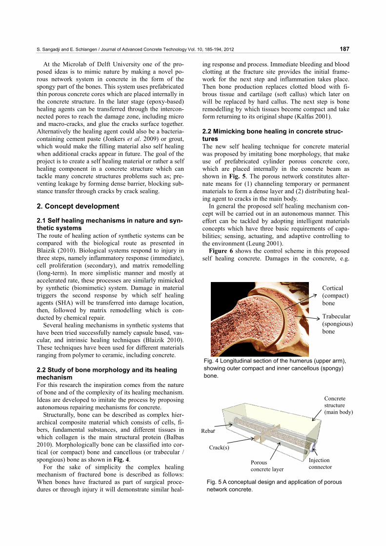
Structurally, bone can be described as complex hier-archical composite material which consists of cells, fi-bers, fundamental substances, and different tissues in which collagen is the main structural protein (Balbas 2010). Morphologically bone can be classified into cor-tical (or compact) bone and cancellous (or trabecular / spongious) bone as shown in Fig. 4.
For the sake of simplicity the complex healing mechanism of fractured bone is described as follows: When bones have fractured as part of surgical proce-dures or through injury it will demonstrate similar heal-
ing response and process. Immediate bleeding and blood clotting at the fracture site provides the initial frame-work for the next step and inflammation takes place. Then bone production replaces clotted blood with fi-brous tissue and cartilage (soft callus) which later on will be replaced by hard callus. The next step is bone remodelling by which tissues become compact and take form returning to its original shape (Kalfas 2001).
2.2 Mimicking bone healing in concrete struc-tures The new self healing technique for concrete material was proposed by imitating bone morphology, that make use of prefabricated cylinder porous concrete core, which are placed internally in the concrete beam as shown in Fig. 5. The porous network constitutes alter-nate means for (1) channeling temporary or permanent materials to form a dense layer and (2) distributing heal-ing agent to cracks in the main body.
In general the proposed self healing mechanism con-cept will be carried out in an autonomous manner. This effort can be tackled by adopting intelligent materials concepts which have three basic requirements of capa-bilities; sensing, actuating, and adaptive controlling to the environment (Leung 2001).
Figure 6 shows the control scheme in this proposed self healing concrete. Damages in the concrete, e.g.
Fig. 5 A conceptual design and application of porous network concrete.
Fig. 4 Longitudinal section of the humerus (upper arm), showing outer compact and inner cancellous (spongy) bone.
Cortical (compact) bone
Trabecular (spongious) bone
Injection connector
Rebar
Porous concrete layer
Crack(s)
Concrete structure (main body)
S. Sangadji and E. Schlangen / Journal of Advanced Concrete Technology Vol. 10, 185-194, 2012 188
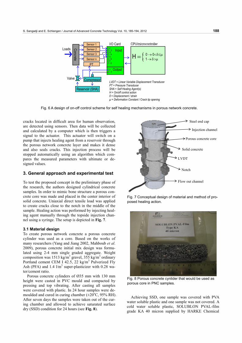
cracks located in difficult area for human observation, are detected using sensors. Then data will be collected and calculated by a computer which is then triggers a signal to the actuator. This actuator will switch on a pump that injects healing agent from a reservoir through the porous network concrete layer and makes it dense and also seals cracks. This injection process will be stopped automatically using an algorithm which com-pares the measured parameters with ultimate or de-signed values.
3. General approach and experimental test
To test the proposed concept in the preliminary phase of the research, the authors designed cylindrical concrete samples. In order to mimic bone structure a porous con-crete core was made and placed in the center interior of solid concrete. Uniaxial direct tensile load was applied to create cracks close to the notch in the middle of the sample. Healing action was performed by injecting heal-ing agent manually through the topside injection chan-nel using a syringe. The setup is depicted in Fig. 7. 3.1 Material design To create porous network concrete a porous concrete cylinder was used as a core. Based on the works of many researchers (Yang and Jiang 2002, Mahboub et al. 2009), porous concrete initial mix design was formu-lated using 2-4 mm single graded aggregate. Weight composition was 1513 kg/m3 gravel, 355 kg/m3 ordinary Portland cement CEM I 42.5, 22 kg/m3 Pulverized Fly Ash (PFA) and 1.4 l/m3 super-plasticizer with 0.28 wa-ter/cement ratio.
Porous concrete cylinders of Ø35 mm with 130 mm height were casted in PVC mould and compacted by pressing and top vibrating. After casting all samples were covered with plastic. In 24 hour samples were de-moulded and cured in curing chamber (±20oC, 95% RH). After seven days the samples were taken out of the cur-ing chamber and allowed to achieve saturated surface dry (SSD) condition for 24 hours (see Fig. 8).
Achieving SSD, one sample was covered with PVA water soluble plastic and one sample was not covered. A cold water soluble plastic, SOLUBLON PVAL-film grade KA 40 micron supplied by HARKE Chemical
12
34
56
78
12
Sensor 1 Sensor 2 Sensor 3
Sensor n
Compressor
PT
Reservoir (SHA)
Concrete
I/O Card CPU/microcontrollerInput
Output
Valve
Loads
LVDT = Linear Variable Displacement Transducer PT = Pressure Transducer SHA = Self Healing Agent(s) H = On/off control action δ = Displacement / strain µ = Deformation Constant / Crack tip opening
{ 0 01H → <δ≤μ→δ>μ=
Fig. 6 A design of on-off control scheme for self healing mechanisms in porous network concrete.
Fig. 8 Porous concrete cynlider that would be used as porous core in PNC samples.
Steel end cap
Injection channel
Porous concrete core
Solid concrete
LVDT
Flow out channel
Notch
Fig. 7 Conceptual design of material and method of pro-posed healing action.
S. Sangadji and E. Schlangen / Journal of Advanced Concrete Technology Vol. 10, 185-194, 2012 189
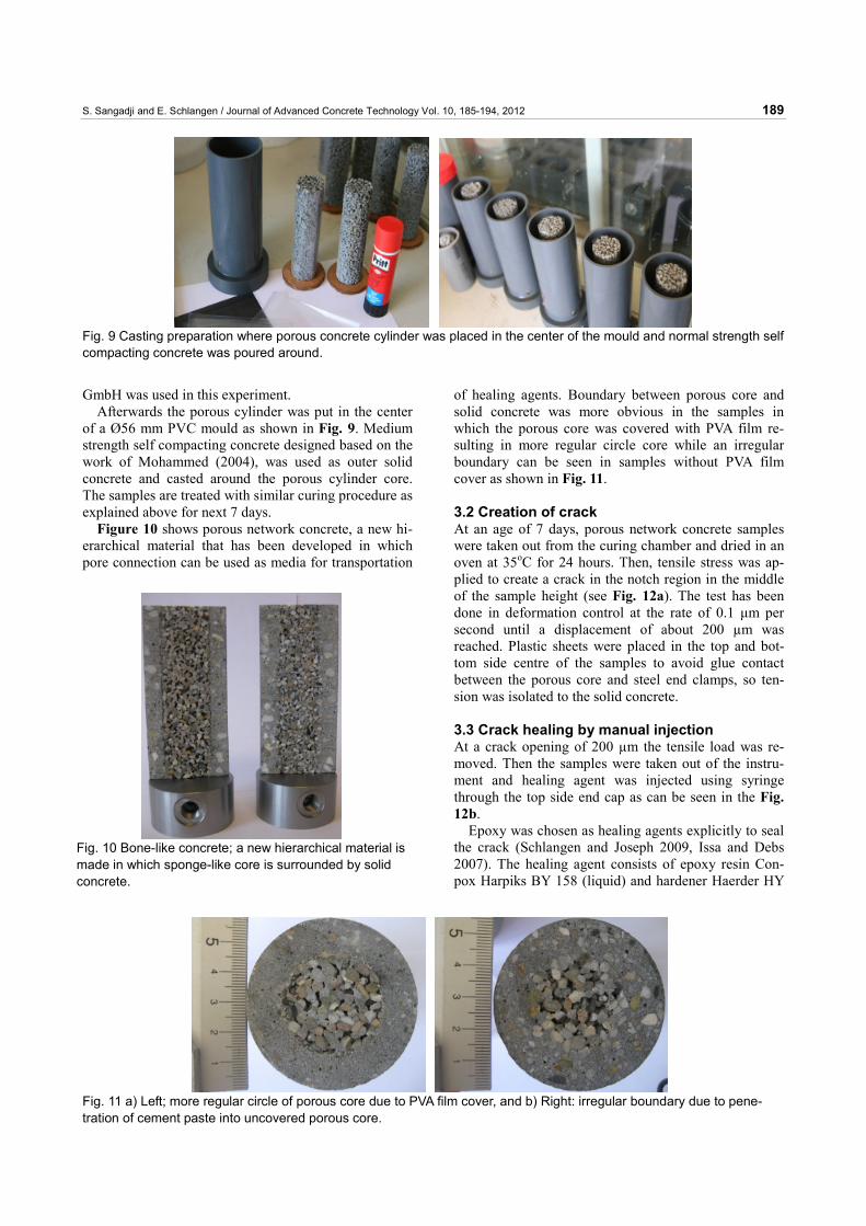
GmbH was used in this experiment. Afterwards the porous cylinder was put in the center
of a Ø56 mm PVC mould as shown in Fig. 9. Medium strength self compacting concrete designed based on the work of Mohammed (2004), was used as outer solid concrete and casted around the porous cylinder core. The samples are treated with similar curing procedure as explained above for next 7 days.
Figure 10 shows porous network concrete, a new hi-erarchical material that has been developed in which pore connection can be used as media for transportation
of healing agents. Boundary between porous core and solid concrete was more obvious in the samples in which the porous core was covered with PVA film re-sulting in more regular circle core while an irregular boundary can be seen in samples without PVA film cover as shown in Fig. 11.
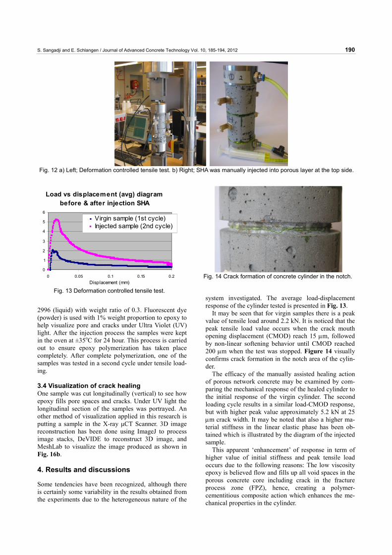
3.2 Creation of crack At an age of 7 days, porous network concrete samples were taken out from the curing chamber and dried in an oven at 35oC for 24 hours. Then, tensile stress was ap-plied to create a crack in the notch region in the middle of the sample height (see Fig. 12a). The test has been done in deformation control at the rate of 0.1 μm per second until a displacement of about 200 µm was reached. Plastic sheets were placed in the top and bot-tom side centre of the samples to avoid glue contact between the porous core and steel end clamps, so ten-sion was isolated to the solid concrete. 3.3 Crack healing by manual injection At a crack opening of 200 µm the tensile load was re-moved. Then the samples were taken out of the instru-ment and healing agent was injected using syringe through the top side end cap as can be seen in the Fig. 12b.
Epoxy was chosen as healing agents explicitly to seal the crack (Schlangen and Joseph 2009, Issa and Debs 2007). The healing agent consists of epoxy resin Con-pox Harpiks BY 158 (liquid) and hardener Haerder HY
Fig. 9 Casting preparation where porous concrete cylinder was placed in the center of the mould and normal strength self compacting concrete was poured around.
Fig. 10 Bone-like concrete; a new hierarchical material is made in which sponge-like core is surrounded by solid concrete.
Fig. 11 a) Left; more regular circle of porous core due to PVA film cover, and b) Right: irregular boundary due to pene-tration of cement paste into uncovered porous core.
S. Sangadji and E. Schlangen / Journal of Advanced Concrete Technology Vol. 10, 185-194, 2012 190
2996 (liquid) with weight ratio of 0.3. Fluorescent dye (powder) is used with 1% weight proportion to epoxy to help visualize pore and cracks under Ultra Violet (UV) light. After the injection process the samples were kept in the oven at ±35oC for 24 hour. This process is carried out to ensure epoxy polymerization has taken place completely. After complete polymerization, one of the samples was tested in a second cycle under tensile load-ing.
3.4 Visualization of crack healing One sample was cut longitudinally (vertical) to see how epoxy fills pore spaces and cracks. Under UV light the longitudinal section of the samples was portrayed. An other method of visualization applied in this research is putting a sample in the X-ray μCT Scanner. 3D image reconstruction has been done using ImageJ to process image stacks, DeVIDE to reconstruct 3D image, and MeshLab to visualize the image produced as shown in Fig. 16b. 4. Results and discussions
Some tendencies have been recognized, although there is certainly some variability in the results obtained from the experiments due to the heterogeneous nature of the
system investigated. The average load-displacement response of the cylinder tested is presented in Fig. 13.
It may be seen that for virgin samples there is a peak value of tensile load around 2.2 kN. It is noticed that the peak tensile load value occurs when the crack mouth opening displacement (CMOD) reach 15 μm, followed by non-linear softening behavior until CMOD reached 200 μm when the test was stopped. Figure 14 visually confirms crack formation in the notch area of the cylin-der.
The efficacy of the manually assisted healing action of porous network concrete may be examined by com-paring the mechanical response of the healed cylinder to the initial response of the virgin cylinder. The second loading cycle results in a similar load-CMOD response, but with higher peak value approximately 5.2 kN at 25 μm crack width. It may be noted that also a higher ma-terial stiffness in the linear elastic phase has been ob-tained which is illustrated by the diagram of the injected sample.
This apparent ‘enhancement’ of response in term of higher value of initial stiffness and peak tensile load occurs due to the following reasons: The low viscosity epoxy is believed flow and fills up all void spaces in the porous concrete core including crack in the fracture process zone (FPZ), hence, creating a polymer-cementitious composite action which enhances the me-chanical properties in the cylinder.
Fig. 12 a) Left; Deformation controlled tensile test. b) Right; SHA was manually injected into porous layer at the top side.
Load vs displacement (avg) diagrambefore & after injection SHA
0
1
2
3
4
5
6
0 0.05 0.1 0.15 0.2Displacement (mm)
Virgin sample (1st cycle)Injected sample (2nd cycle)
Fig. 13 Deformation controlled tensile test.
Fig. 14 Crack formation of concrete cylinder in the notch.
S. Sangadji and E. Schlangen / Journal of Advanced Concrete Technology Vol. 10, 185-194, 2012 191
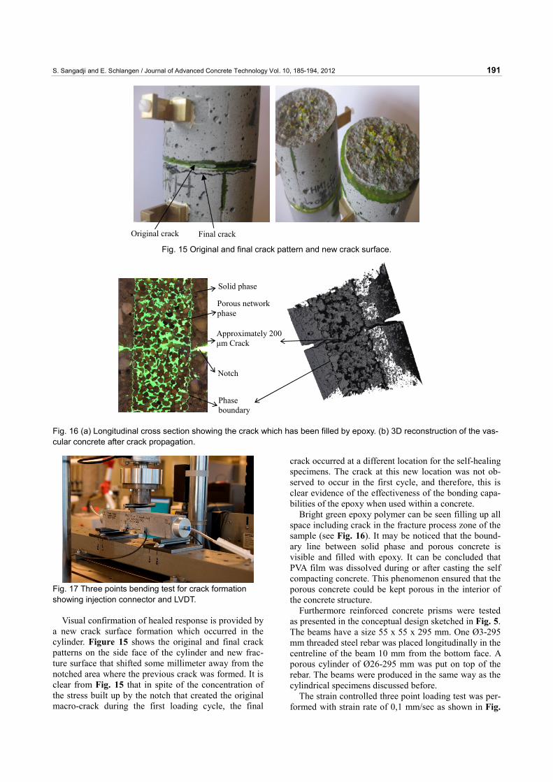
Visual confirmation of healed response is provided by a new crack surface formation which occurred in the cylinder. Figure 15 shows the original and final crack patterns on the side face of the cylinder and new frac-ture surface that shifted some millimeter away from the notched area where the previous crack was formed. It is clear from Fig. 15 that in spite of the concentration of the stress built up by the notch that created the original macro-crack during the first loading cycle, the final
crack occurred at a different location for the self-healing specimens. The crack at this new location was not ob-served to occur in the first cycle, and therefore, this is clear evidence of the effectiveness of the bonding capa-bilities of the epoxy when used within a concrete.
Bright green epoxy polymer can be seen filling up all space including crack in the fracture process zone of the sample (see Fig. 16). It may be noticed that the bound-ary line between solid phase and porous concrete is visible and filled with epoxy. It can be concluded that PVA film was dissolved during or after casting the self compacting concrete. This phenomenon ensured that the porous concrete could be kept porous in the interior of the concrete structure.
Furthermore reinforced concrete prisms were tested as presented in the conceptual design sketched in Fig. 5. The beams have a size 55 x 55 x 295 mm. One Ø3-295 mm threaded steel rebar was placed longitudinally in the centreline of the beam 10 mm from the bottom face. A porous cylinder of Ø26-295 mm was put on top of the rebar. The beams were produced in the same way as the cylindrical specimens discussed before.
The strain controlled three point loading test was per-formed with strain rate of 0,1 mm/sec as shown in Fig.
Fig. 15 Original and final crack pattern and new crack surface.
Final crack Original crack
Approximately 200 μm Crack
Notch
Solid phase
Porous network phase
Phase boundary
Fig. 16 (a) Longitudinal cross section showing the crack which has been filled by epoxy. (b) 3D reconstruction of the vas-cular concrete after crack propagation.
Fig. 17 Three points bending test for crack formation showing injection connector and LVDT.
S. Sangadji and E. Schlangen / Journal of Advanced Concrete Technology Vol. 10, 185-194, 2012 192
17. The beam was simply supported by steel cylinder with 250 mm span and the load was right in the mid-span. To control and measure the crack width during the test a linear variable differential transformers (LVDT) which has a range of ± 500 μm with an accuracy of 1 μm was attached to the beam, one on each side of the beam specimen at the bottom.
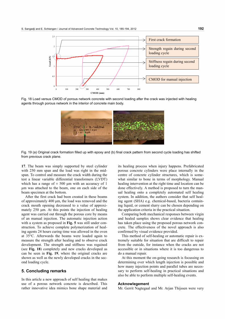
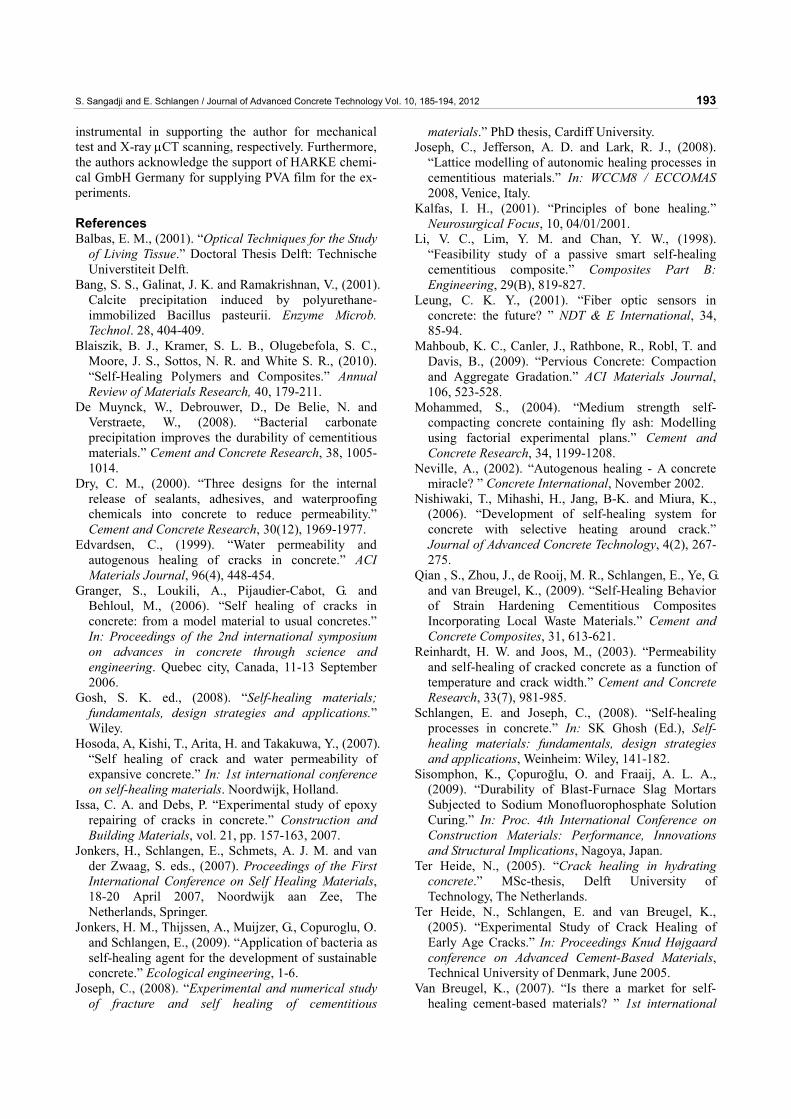
After the first crack had been created in these beams of approximately 400 μm, the load was removed and the crack mouth opening decreased to a value of approxi-mately 250 μm. At this points the injection of healing agent was carried out through the porous core by means of an manual injection. The automatic injection action with a system as proposed in Fig. 5 was still under con-struction. To achieve complete polymerization of heal-ing agents 24 hours curing time was allowed in the oven at 35°C. Afterwards the beams were loaded again to measure the strength after healing and to observe crack development. The strength and stiffness was regained (see Fig. 18) completely and new cracks developed as can be seen in Fig. 19, where the original cracks are shown as well as the newly developed cracks in the sec-ond loading cycle.
5. Concluding remarks
In this article a new approach of self healing that makes use of a porous network concrete is described. This rather innovative idea mimics bone shape material and
its healing process when injury happens. Prefabricated porous concrete cylinders were place internally in the centre of concrete cylinder structures, which is some-what similar to bone in terms of morphology. Manual healing intervention at the right time and location can be done effectively. A method is proposed to turn the man-ual healing onto a completely automated self healing system. In addition, the authors consider that self heal-ing agent (SHA) e.g. chemical-based, bacteria contain-ing liquid, or cement slurry can be chosen depending on the application criteria in the practical situation.
Comparing both mechanical responses between virgin and healed samples shows clear evidence that healing has taken place using the proposed porous network con-crete. The effectiveness of the novel approach is also confirmed by visual evidence provided.
This method of self-healing or automatic repair is ex-tremely suitable for situation that are difficult to repair from the outside, for instance when the cracks are not accessible or in situations where it is too dangerous to do a manual repair.
At this moment the on-going research is focussing on determining over which length injection is possible and how many injection points and parallel tubes are neces-sary to perform self-healing in practical situations and also be able to perform multiple self-healing events.
Acknowlegement Mr. Gerrit Nagtegaal and Mr. Arjan Thijssen were very
0
0.5
1
1.5
2
2.5
0 100 200 300 400 500 600 700 800
CMOD (mm)
Loa
d (k
N)
CMOD for manual injection
First crack formation
Strength regain during second loading cycle
Stiffness regain during second loading cycle
Fig. 18 Load versus CMOD of porous network concrete with second loading after the crack was injected with healing agents through porous network in the interior of concrete main body.
Fig. 19 (a) Original crack formation filled up with epoxy and (b) final crack pattern from second cycle loading has shifted from previous crack plane.
S. Sangadji and E. Schlangen / Journal of Advanced Concrete Technology Vol. 10, 185-194, 2012 193
instrumental in supporting the author for mechanical test and X-ray μCT scanning, respectively. Furthermore, the authors acknowledge the support of HARKE chemi-cal GmbH Germany for supplying PVA film for the ex-periments. References Balbas, E. M., (2001). “Optical Techniques for the Study
of Living Tissue.” Doctoral Thesis Delft: Technische Universtiteit Delft.
Bang, S. S., Galinat, J. K. and Ramakrishnan, V., (2001). Calcite precipitation induced by polyurethane-immobilized Bacillus pasteurii. Enzyme Microb. Technol. 28, 404-409.
Blaiszik, B. J., Kramer, S. L. B., Olugebefola, S. C., Moore, J. S., Sottos, N. R. and White S. R., (2010). “Self-Healing Polymers and Composites.” Annual Review of Materials Research, 40, 179-211.
De Muynck, W., Debrouwer, D., De Belie, N. and Verstraete, W., (2008). “Bacterial carbonate precipitation improves the durability of cementitious materials.” Cement and Concrete Research, 38, 1005-1014.
Dry, C. M., (2000). “Three designs for the internal release of sealants, adhesives, and waterproofing chemicals into concrete to reduce permeability.” Cement and Concrete Research, 30(12), 1969-1977.
Edvardsen, C., (1999). “Water permeability and autogenous healing of cracks in concrete.” ACI Materials Journal, 96(4), 448-454.
Granger, S., Loukili, A., Pijaudier-Cabot, G. and Behloul, M., (2006). “Self healing of cracks in concrete: from a model material to usual concretes.” In: Proceedings of the 2nd international symposium on advances in concrete through science and engineering. Quebec city, Canada, 11-13 September 2006.
Gosh, S. K. ed., (2008). “Self-healing materials; fundamentals, design strategies and applications.” Wiley.
Hosoda, A, Kishi, T., Arita, H. and Takakuwa, Y., (2007). “Self healing of crack and water permeability of expansive concrete.” In: 1st international conference on self-healing materials. Noordwijk, Holland.
Issa, C. A. and Debs, P. “Experimental study of epoxy repairing of cracks in concrete.” Construction and Building Materials, vol. 21, pp. 157-163, 2007.
Jonkers, H., Schlangen, E., Schmets, A. J. M. and van der Zwaag, S. eds., (2007). Proceedings of the First International Conference on Self Healing Materials, 18-20 April 2007, Noordwijk aan Zee, The Netherlands, Springer.
Jonkers, H. M., Thijssen, A., Muijzer, G., Copuroglu, O. and Schlangen, E., (2009). “Application of bacteria as self-healing agent for the development of sustainable concrete.” Ecological engineering, 1-6.
Joseph, C., (2008). “Experimental and numerical study of fracture and self healing of cementitious
materials.” PhD thesis, Cardiff University. Joseph, C., Jefferson, A. D. and Lark, R. J., (2008).
“Lattice modelling of autonomic healing processes in cementitious materials.” In: WCCM8 / ECCOMAS 2008, Venice, Italy.
Kalfas, I. H., (2001). “Principles of bone healing.” Neurosurgical Focus, 10, 04/01/2001.
Li, V. C., Lim, Y. M. and Chan, Y. W., (1998). “Feasibility study of a passive smart self-healing cementitious composite.” Composites Part B: Engineering, 29(B), 819-827.
Leung, C. K. Y., (2001). “Fiber optic sensors in concrete: the future? ” NDT & E International, 34, 85-94.
Mahboub, K. C., Canler, J., Rathbone, R., Robl, T. and Davis, B., (2009). “Pervious Concrete: Compaction and Aggregate Gradation.” ACI Materials Journal, 106, 523-528.
Mohammed, S., (2004). “Medium strength self-compacting concrete containing fly ash: Modelling using factorial experimental plans.” Cement and Concrete Research, 34, 1199-1208.
Neville, A., (2002). “Autogenous healing - A concrete miracle? ” Concrete International, November 2002.
Nishiwaki, T., Mihashi, H., Jang, B-K. and Miura, K., (2006). “Development of self-healing system for concrete with selective heating around crack.” Journal of Advanced Concrete Technology, 4(2), 267-275.
Qian , S., Zhou, J., de Rooij, M. R., Schlangen, E., Ye, G. and van Breugel, K., (2009). “Self-Healing Behavior of Strain Hardening Cementitious Composites Incorporating Local Waste Materials.” Cement and Concrete Composites, 31, 613-621.
Reinhardt, H. W. and Joos, M., (2003). “Permeability and self-healing of cracked concrete as a function of temperature and crack width.” Cement and Concrete Research, 33(7), 981-985.
Schlangen, E. and Joseph, C., (2008). “Self-healing processes in concrete.” In: SK Ghosh (Ed.), Self-healing materials: fundamentals, design strategies and applications, Weinheim: Wiley, 141-182.
Sisomphon, K., Çopuroğlu, O. and Fraaij, A. L. A., (2009). “Durability of Blast-Furnace Slag Mortars Subjected to Sodium Monofluorophosphate Solution Curing.” In: Proc. 4th International Conference on Construction Materials: Performance, Innovations and Structural Implications, Nagoya, Japan.
Ter Heide, N., (2005). “Crack healing in hydrating concrete.” MSc-thesis, Delft University of Technology, The Netherlands.
Ter Heide, N., Schlangen, E. and van Breugel, K., (2005). “Experimental Study of Crack Healing of Early Age Cracks.” In: Proceedings Knud Højgaard conference on Advanced Cement-Based Materials, Technical University of Denmark, June 2005.
Van Breugel, K., (2007). “Is there a market for self-healing cement-based materials? ” 1st international
S. Sangadji and E. Schlangen / Journal of Advanced Concrete Technology Vol. 10, 185-194, 2012 194
conference on self-healing materials. Noordwijk, Holland, 2007.
Van der Zwaag, S. (ed), Self healing materials : an alternative approach to 20 centuries of materials science, Dordrecht, Netherlands, Springer, 2007.
Van Tittelboom, K., De Belie, N, Van Loo, D. and Jacobs, P., (2011). “Self-healing efficiency of cementitious materials containing tubular capsules filled with healing agent.” Cement and Concrete Composites, 33(4), 497-505.
Wiktor, V. and Jonkers, H. M., (2011). “Quantification of crack-healing in novel bacteria-based self-healing concrete.” Cement and Concrete Composites, 33, 763-770.
www.selfhealingconcrete.blogspot.com [Accessed 29 February 2012]
Yang J. and Jiang, G., (2002). “Experimental study on properties of pervious concrete pavement materials.” Cement and Concrete Research, 33, 381-386.