Embed Size (px)
Citation preview
Self-Decoupled Porphyrin with a Tripodal Anchor for Molecular-ScaleElectroluminescenceSan-E Zhu,†,‡ Yan-Min Kuang,† Feng Geng,† Jia-Zhe Zhu,† Cong-Zhou Wang,†,‡ Yun-Jie Yu,† Yang Luo,†
Yang Xiao,†,‡ Kai-Qing Liu,†,‡ Qiu-Shi Meng,† Li Zhang,† Song Jiang,† Yang Zhang,† Guan-Wu Wang,*,†,‡
Zhen-Chao Dong,*,† and J. G. Hou†
†Hefei National Laboratory for Physical Sciences at the Microscale and ‡CAS Key Laboratory of Soft Matter Chemistry andDepartment of Chemistry, University of Science and Technology of China, Hefei, Anhui 230026, China
*S Supporting Information
ABSTRACT: A self-decoupled porphyrin with a tripodal anchor has been synthesized anddeposited on Au(111) using different wet-chemistry methods. Nanoscale electroluminescence fromsingle porphyrin molecules or aggregates on Au(111) has been realized by tunneling electronexcitation. The molecular origin of the luminescence is established by the vibrationally resolvedfluorescence spectra observed. The rigid tripodal anchor not only acts as a decoupling spacer butalso controls the orientation of the molecule. Intense molecular electroluminescence can beobtained from the emission enhancement provided by a good coupling between the moleculartransition dipole and the axial nanocavity plasmon. The unipolar performance of theelectroluminescence from the designed tripodal molecule suggests that the porphyrin molecule islikely to be excited by the injection of hot electrons, and then the excited state decays radiativelythrough Franck−Condon π*−π transitions. These results open up a new route to generatingelectrically driven nanoscale light sources.
■ INTRODUCTION
The highly localized tunneling current in a scanning tunnelingmicroscope (STM) can be used as a source of low-energyelectrons to locally excite photon emission from metals,semiconductors, and organic molecules.1 In recent years,STM-induced luminescence (STML) from organic moleculeson metals has gained much attention for its capability in helpingto develop nanoscale molecular optoelectronics and plas-monics. However, when molecules are directly adsorbed on orvery close to metal surfaces, the intrinsic molecular fluorescencewill be quenched by the strong interaction between themolecules and the substrate.2−9 Decoupling the molecule fromthe substrate underneath is essential to the generation ofmolecule-specific electroluminescence near metals. To date,such decoupling has usually been realized by inserting anadditional spacer layer such as an oxide, halide, or molecularmultilayer in between.2−5,10,11 The idea of chemicallydecoupling the emitter from the metal substrate has beenproposed using a double-decker molecule by Berndt et al.12,13
The molecule thus decoupled is found to modify the plasmonicemission profile dramatically. Nevertheless, the plasmonicnature in the observed emission suggests that the decouplingstrength may still not be sufficient to generate intrinsicmolecular fluorescence. Sufficient electronic decoupling andfavorable axial dipole orientations are both believed to beimportant factors in the generation of molecule-specificfluorescence.8,10,11,14,15 In this work, we explore the chemicalapproach to achieving molecule-specific emission by buildingthe spacer and emitter together within a single molecule with
controlled orientations. We shall describe the design strategy ofa self-decoupled porphyrin molecule (abbreviated as 1) bearinga rigid tripodal anchor. The challenges of its synthesis,deposition on metals, and clear characterization by STMLwill be addressed. Interestingly, different wet-chemistrydeposition methods have been found to affect the adsorptionconfiguration of molecules on the metal surface and resultantelectroluminescent properties. A new understanding of theexcitation mechanism of molecular electroluminescence in theSTM junction will also be discussed briefly.
■ RESULTS AND DISCUSSION
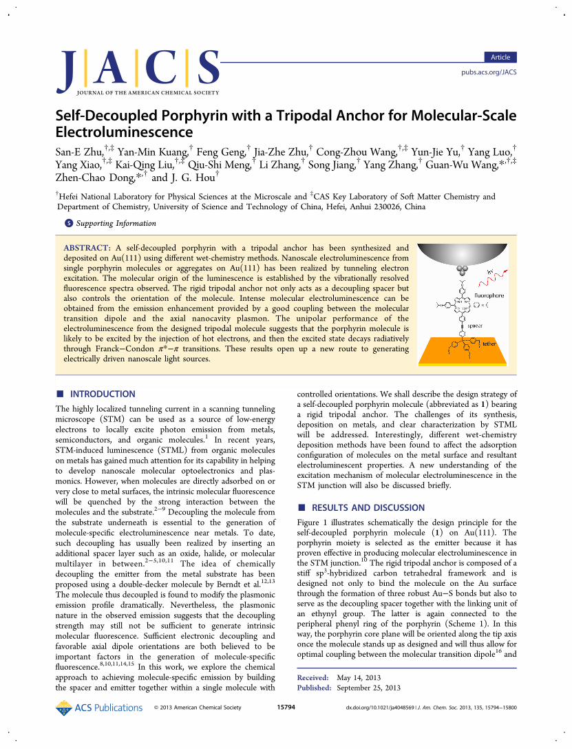
Figure 1 illustrates schematically the design principle for theself-decoupled porphyrin molecule (1) on Au(111). Theporphyrin moiety is selected as the emitter because it hasproven effective in producing molecular electroluminescence inthe STM junction.10 The rigid tripodal anchor is composed of astiff sp3-hybridized carbon tetrahedral framework and isdesigned not only to bind the molecule on the Au surfacethrough the formation of three robust Au−S bonds but also toserve as the decoupling spacer together with the linking unit ofan ethynyl group. The latter is again connected to theperipheral phenyl ring of the porphyrin (Scheme 1). In thisway, the porphyrin core plane will be oriented along the tip axisonce the molecule stands up as designed and will thus allow foroptimal coupling between the molecular transition dipole16 and
Received: May 14, 2013Published: September 25, 2013
Article
pubs.acs.org/JACS
© 2013 American Chemical Society 15794 dx.doi.org/10.1021/ja4048569 | J. Am. Chem. Soc. 2013, 135, 15794−15800
the axial nanocavity plasmon (NCP), which is expected toprovide maximal emission enhancement.8,10,11,14,15 The opti-mized structure of 1 has a height of ∼3.1 nm and a width of∼2.3 nm as well as a spacer length of ∼1.5 nm.However, the multifunctionalized complexity and the
relatively large size of target molecule 1 make the samplepreparation a nontrivial task, which includes both the synthesisof high-purity materials in high yield and the deposition ofmolecules on the metal surface with well-defined structures forSTM studies. The synthesis procedure for 1 is shown inScheme 1. The iodo-substituted tripodal rigid anchor (Tpd-I)
was synthesized by starting from commercially available tolueneand carbon tetrachloride, in reference to protocols reported inthe literature.17−23 The synthesis and isolation of theunsymmetrical porphyrin in high yield often encounterdifficulties and require careful consideration in tuning themolecular solubility and polarity. 4-Isopropoxybenzaldehydewas selected to improve the solubilities and to discriminate thepolarities among the porphyryin mixtures so that efficientisolation can be achieved. The condensation of pyrrole with 4-isopropoxybenzaldehyde and 4-bromobenzaldehyde in a molarratio of 5:4:1 using the Alder−Longo method24 gave porphyrin2 in 6% yield. 2 was then metallized by zinc acetate dihydrate toyield zinc porphyrin 3 in a yield of 93%. Sonogashira couplingof 3 with trimethylsilyacetylene (TMSA) afforded 4 in 70%yield. Deprotection of the TMS group in 4 with tetrabuty-lammonium fluoride (TBAF) produced 5 in 82% yield. Thecross-coupling reaction of 5 with Tpd-I furnished 6 in 63%yield. Subsequent hydrolysis under acidic conditions to stripboth the acetyl group and Zn(II) at the same time producedtarget free-base porphyrin molecule 1 with three mercapto-methyl anchor groups in 84% yield. All new compounds (1−6)were purified by column chromatography on silica gel andcharacterized using various spectroscopic methods including 1Hand 13C NMR spectroscopy and ESI- or MALDI-TOF massspectrometry. More details on the synthesis can be found in theExperimental Section. The thermal analysis data of 1 can befound in the Supporting Information (SI).The luminescence property of the molecule thus designed
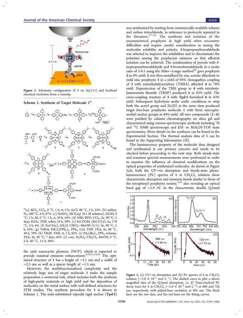
and synthesized is our primary concern and needs to bechecked before proceeding to the next step. Both steady-stateand transient spectral measurements were performed in orderto examine the influence of chemical modifications on theoptical properties of synthesized molecules. As shown in Figure2a,b, both the UV−vis absorption and steady-state photo-luminescence (PL) spectra of 1 in CH2Cl2 solution showcharacteristic absorption and emission bands similar to those ofthe tetraphenyl porphyrin moiety,4,10 also revealing an opticalband gap of ∼1.9 eV. In the characteristic double Q-band
Figure 1. Schematic configuration of 1 on Au(111) and localizedelectrical excitation from a nanotip.
Scheme 1. Synthesis of Target Molecule 1a
a(a) AlCl3, CCl4, 0 °C, 1 h, rt, 2 h; AcCl, 80 °C, 2 h, 25%. (b) aniline,N2, 200 °C, 6 h, 87%. (c) NaNO2, HCl(aq) (6.1 M solution), EtOH, 0°C, 1 h; KI, 0 °C, 1 h, rt, 19 h, 54%. (d) NBS, BPO, CCl4, Ar, 90 °C, 3days; KSAc, THF, reflux, 24 h, 39%. (e) EtCOOH, (EtCO)2O, Ar, 170°C, 3 h, 6%. (f) Zn(OAc)2·2H2O, CHCl3−MeOH (3/1), Ar, 80 °C, 5h, 93%. (g) TMSA, PdCl2(PPh3)2, PPh3, CuI, THF, TEA, Ar, 80 °C,48 h, 70%. (h) TBAF, THF, rt, 1 h, 82%. (i) Pd2(dba)3, PPh3, toluene,TEA, Ar, 30 °C, 7 days, 63%. (j) conc. H2SO4, CH2Cl2, MeOH, 0 °C,2 h, 60 °C, 12 h, 84%.
Figure 2. (a) UV−vis absorption and (b) PL spectra of 1 in CH2Cl2solution (∼1.0 × 10⁻⁵ mol L−1). The dashed curve in plot a showsmagnified data of the Q-band absorption. (c, d) Time-resolved PLdecay trace for 1 in CH2Cl2 (∼1.0 × 10⁻⁸ mol L−1) at 660 and 726nm, respectively, with pulsed-laser excitation at 405 nm. The blacklines are the raw data, and the red lines are the fitting curves.
Journal of the American Chemical Society Article
dx.doi.org/10.1021/ja4048569 | J. Am. Chem. Soc. 2013, 135, 15794−1580015795
emission associated with the π*−π transitions of the conjugateporphyrin plane, the band at ∼660 nm is attributed to theQx(0,0) transition whereas the band at ∼726 nm is attributedto the Qx(0,1) transition.4,16 More importantly, the time-resolved fluorescence decay data in Figure 2c,d reveal clearsingle-exponential decay behavior for both emission bands, withlifetimes of ∼7.86 ns at 660 nm and ∼7.72 ns at 726 nm. Theselifetimes are very close to the monomer lifetime of ∼8.38 ns forthe tetraphenyl porphyrin,9 which suggests that the chemicalmodifications do not generate additional nonradiative channelsthat would otherwise quench the molecular fluorescence. Thedesigned self-decoupled porphyrin molecule thus appears to bea good candidate as an emitter for STML studies.For large multifunctionalized molecules such as 1, vacuum
sublimation methods are no longer suitable because themolecules will decompose during heating. Instead, weemployed wet-chemistry methods to deposit 1 on Au(111).In an effort to reduce contamination, we first performed thedeposition experiment in the load-lock chamber under anitrogen-gas atmosphere via short-time drop-casting of 1(∼10−6 mol/L in CH2Cl2) onto the atomically cleanedAu(111) surface.As shown in Figure 3a, there are isolated multidot features on
the STM image of the as-prepared sample, which, for the sake
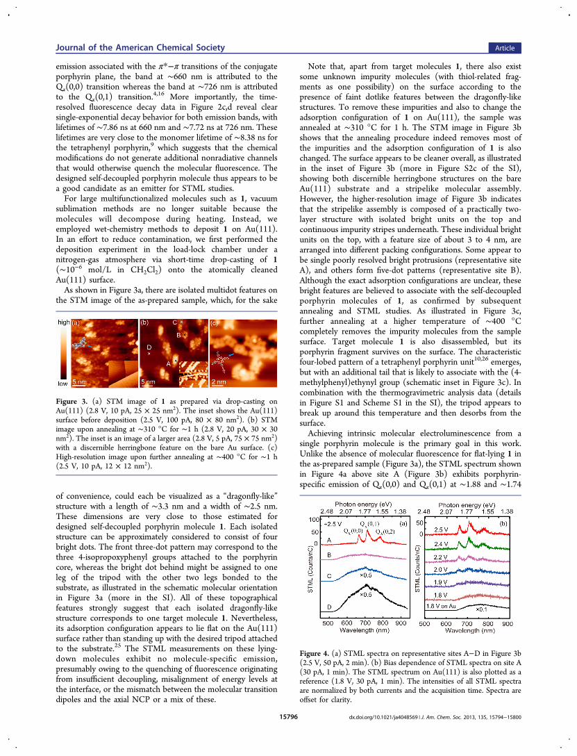
of convenience, could each be visualized as a “dragonfly-like”structure with a length of ∼3.3 nm and a width of ∼2.5 nm.These dimensions are very close to those estimated fordesigned self-decoupled porphyrin molecule 1. Each isolatedstructure can be approximately considered to consist of fourbright dots. The front three-dot pattern may correspond to thethree 4-isopropoxyphenyl groups attached to the porphyrincore, whereas the bright dot behind might be assigned to oneleg of the tripod with the other two legs bonded to thesubstrate, as illustrated in the schematic molecular orientationin Figure 3a (more in the SI). All of these topographicalfeatures strongly suggest that each isolated dragonfly-likestructure corresponds to one target molecule 1. Nevertheless,its adsorption configuration appears to lie flat on the Au(111)surface rather than standing up with the desired tripod attachedto the substrate.25 The STML measurements on these lying-down molecules exhibit no molecule-specific emission,presumably owing to the quenching of fluorescence originatingfrom insufficient decoupling, misalignment of energy levels atthe interface, or the mismatch between the molecular transitiondipoles and the axial NCP or a mix of these.
Note that, apart from target molecules 1, there also existsome unknown impurity molecules (with thiol-related frag-ments as one possibility) on the surface according to thepresence of faint dotlike features between the dragonfly-likestructures. To remove these impurities and also to change theadsorption configuration of 1 on Au(111), the sample wasannealed at ∼310 °C for 1 h. The STM image in Figure 3bshows that the annealing procedure indeed removes most ofthe impurities and the adsorption configuration of 1 is alsochanged. The surface appears to be cleaner overall, as illustratedin the inset of Figure 3b (more in Figure S2c of the SI),showing both discernible herringbone structures on the bareAu(111) substrate and a stripelike molecular assembly.However, the higher-resolution image of Figure 3b indicatesthat the stripelike assembly is composed of a practically two-layer structure with isolated bright units on the top andcontinuous impurity stripes underneath. These individual brightunits on the top, with a feature size of about 3 to 4 nm, arearranged into different packing configurations. Some appear tobe single poorly resolved bright protrusions (representative siteA), and others form five-dot patterns (representative site B).Although the exact adsorption configurations are unclear, thesebright features are believed to associate with the self-decoupledporphyrin molecules of 1, as confirmed by subsequentannealing and STML studies. As illustrated in Figure 3c,further annealing at a higher temperature of ∼400 °Ccompletely removes the impurity molecules from the samplesurface. Target molecule 1 is also disassembled, but itsporphyrin fragment survives on the surface. The characteristicfour-lobed pattern of a tetraphenyl porphyrin unit10,26 emerges,but with an additional tail that is likely to associate with the (4-methylphenyl)ethynyl group (schematic inset in Figure 3c). Incombination with the thermogravimetric analysis data (detailsin Figure S1 and Scheme S1 in the SI), the tripod appears tobreak up around this temperature and then desorbs from thesurface.Achieving intrinsic molecular electroluminescence from a
single porphyrin molecule is the primary goal in this work.Unlike the absence of molecular fluorescence for flat-lying 1 inthe as-prepared sample (Figure 3a), the STML spectrum shownin Figure 4a above site A (Figure 3b) exhibits porphyrin-specific emission of Qx(0,0) and Qx(0,1) at ∼1.88 and ∼1.74
Figure 3. (a) STM image of 1 as prepared via drop-casting onAu(111) (2.8 V, 10 pA, 25 × 25 nm2). The inset shows the Au(111)surface before deposition (2.5 V, 100 pA, 80 × 80 nm2). (b) STMimage upon annealing at ∼310 °C for ∼1 h (2.8 V, 20 pA, 30 × 30nm2). The inset is an image of a larger area (2.8 V, 5 pA, 75 × 75 nm2)with a discernible herringbone feature on the bare Au surface. (c)High-resolution image upon further annealing at ∼400 °C for ∼1 h(2.5 V, 10 pA, 12 × 12 nm2).
Figure 4. (a) STML spectra on representative sites A−D in Figure 3b(2.5 V, 50 pA, 2 min). (b) Bias dependence of STML spectra on site A(30 pA, 1 min). The STML spectrum on Au(111) is also plotted as areference (1.8 V, 30 pA, 1 min). The intensities of all STML spectraare normalized by both currents and the acquisition time. Spectra areoffset for clarity.
Journal of the American Chemical Society Article
dx.doi.org/10.1021/ja4048569 | J. Am. Chem. Soc. 2013, 135, 15794−1580015796
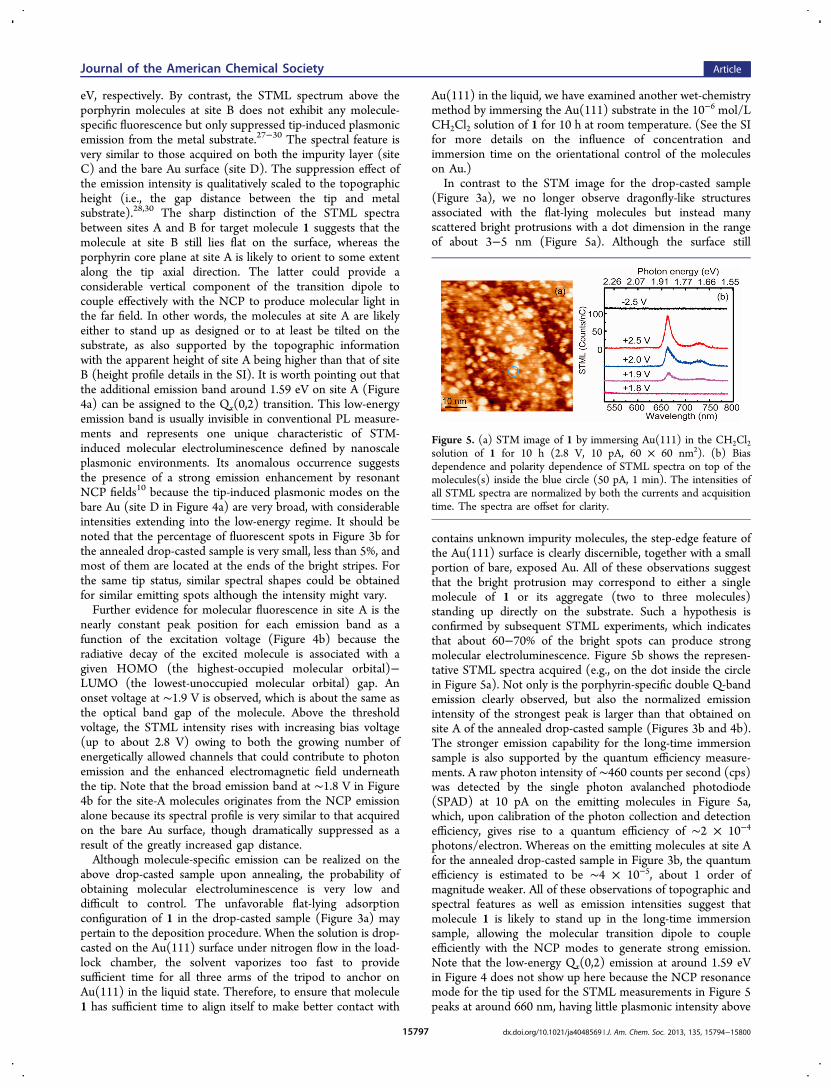
eV, respectively. By contrast, the STML spectrum above theporphyrin molecules at site B does not exhibit any molecule-specific fluorescence but only suppressed tip-induced plasmonicemission from the metal substrate.27−30 The spectral feature isvery similar to those acquired on both the impurity layer (siteC) and the bare Au surface (site D). The suppression effect ofthe emission intensity is qualitatively scaled to the topographicheight (i.e., the gap distance between the tip and metalsubstrate).28,30 The sharp distinction of the STML spectrabetween sites A and B for target molecule 1 suggests that themolecule at site B still lies flat on the surface, whereas theporphyrin core plane at site A is likely to orient to some extentalong the tip axial direction. The latter could provide aconsiderable vertical component of the transition dipole tocouple effectively with the NCP to produce molecular light inthe far field. In other words, the molecules at site A are likelyeither to stand up as designed or to at least be tilted on thesubstrate, as also supported by the topographic informationwith the apparent height of site A being higher than that of siteB (height profile details in the SI). It is worth pointing out thatthe additional emission band around 1.59 eV on site A (Figure4a) can be assigned to the Qx(0,2) transition. This low-energyemission band is usually invisible in conventional PL measure-ments and represents one unique characteristic of STM-induced molecular electroluminescence defined by nanoscaleplasmonic environments. Its anomalous occurrence suggeststhe presence of a strong emission enhancement by resonantNCP fields10 because the tip-induced plasmonic modes on thebare Au (site D in Figure 4a) are very broad, with considerableintensities extending into the low-energy regime. It should benoted that the percentage of fluorescent spots in Figure 3b forthe annealed drop-casted sample is very small, less than 5%, andmost of them are located at the ends of the bright stripes. Forthe same tip status, similar spectral shapes could be obtainedfor similar emitting spots although the intensity might vary.Further evidence for molecular fluorescence in site A is the
nearly constant peak position for each emission band as afunction of the excitation voltage (Figure 4b) because theradiative decay of the excited molecule is associated with agiven HOMO (the highest-occupied molecular orbital)−LUMO (the lowest-unoccupied molecular orbital) gap. Anonset voltage at ∼1.9 V is observed, which is about the same asthe optical band gap of the molecule. Above the thresholdvoltage, the STML intensity rises with increasing bias voltage(up to about 2.8 V) owing to both the growing number ofenergetically allowed channels that could contribute to photonemission and the enhanced electromagnetic field underneaththe tip. Note that the broad emission band at ∼1.8 V in Figure4b for the site-A molecules originates from the NCP emissionalone because its spectral profile is very similar to that acquiredon the bare Au surface, though dramatically suppressed as aresult of the greatly increased gap distance.Although molecule-specific emission can be realized on the
above drop-casted sample upon annealing, the probability ofobtaining molecular electroluminescence is very low anddifficult to control. The unfavorable flat-lying adsorptionconfiguration of 1 in the drop-casted sample (Figure 3a) maypertain to the deposition procedure. When the solution is drop-casted on the Au(111) surface under nitrogen flow in the load-lock chamber, the solvent vaporizes too fast to providesufficient time for all three arms of the tripod to anchor onAu(111) in the liquid state. Therefore, to ensure that molecule1 has sufficient time to align itself to make better contact with
Au(111) in the liquid, we have examined another wet-chemistrymethod by immersing the Au(111) substrate in the 10−6 mol/LCH2Cl2 solution of 1 for 10 h at room temperature. (See the SIfor more details on the influence of concentration andimmersion time on the orientational control of the moleculeson Au.)In contrast to the STM image for the drop-casted sample
(Figure 3a), we no longer observe dragonfly-like structuresassociated with the flat-lying molecules but instead manyscattered bright protrusions with a dot dimension in the rangeof about 3−5 nm (Figure 5a). Although the surface still
contains unknown impurity molecules, the step-edge feature ofthe Au(111) surface is clearly discernible, together with a smallportion of bare, exposed Au. All of these observations suggestthat the bright protrusion may correspond to either a singlemolecule of 1 or its aggregate (two to three molecules)standing up directly on the substrate. Such a hypothesis isconfirmed by subsequent STML experiments, which indicatesthat about 60−70% of the bright spots can produce strongmolecular electroluminescence. Figure 5b shows the represen-tative STML spectra acquired (e.g., on the dot inside the circlein Figure 5a). Not only is the porphyrin-specific double Q-bandemission clearly observed, but also the normalized emissionintensity of the strongest peak is larger than that obtained onsite A of the annealed drop-casted sample (Figures 3b and 4b).The stronger emission capability for the long-time immersionsample is also supported by the quantum efficiency measure-ments. A raw photon intensity of ∼460 counts per second (cps)was detected by the single photon avalanched photodiode(SPAD) at 10 pA on the emitting molecules in Figure 5a,which, upon calibration of the photon collection and detectionefficiency, gives rise to a quantum efficiency of ∼2 × 10⁻⁴
photons/electron. Whereas on the emitting molecules at site Afor the annealed drop-casted sample in Figure 3b, the quantumefficiency is estimated to be ∼4 × 10⁻⁵, about 1 order ofmagnitude weaker. All of these observations of topographic andspectral features as well as emission intensities suggest thatmolecule 1 is likely to stand up in the long-time immersionsample, allowing the molecular transition dipole to coupleefficiently with the NCP modes to generate strong emission.Note that the low-energy Qx(0,2) emission at around 1.59 eVin Figure 4 does not show up here because the NCP resonancemode for the tip used for the STML measurements in Figure 5peaks at around 660 nm, having little plasmonic intensity above
Figure 5. (a) STM image of 1 by immersing Au(111) in the CH2Cl2solution of 1 for 10 h (2.8 V, 10 pA, 60 × 60 nm2). (b) Biasdependence and polarity dependence of STML spectra on top of themolecules(s) inside the blue circle (50 pA, 1 min). The intensities ofall STML spectra are normalized by both the currents and acquisitiontime. The spectra are offset for clarity.
Journal of the American Chemical Society Article
dx.doi.org/10.1021/ja4048569 | J. Am. Chem. Soc. 2013, 135, 15794−1580015797
750 nm. As a result, the conditions for the emissionenhancement of the Qx(0,2) band cannot be created. Theseobservations demonstrate again the spectral shaping capabilityof the resonant NCP modes on molecular fluorescence thanksto greatly enhanced radiative decay rates.10
Figure 5b also reproduces the onset voltage of molecularelectroluminescence at ∼1.9 V and increased emission intensityalong with the increase in bias voltage. Another importantspectral feature in Figure 5b is the highly asymmetricdependency on the bias polarity (e.g., at ±2.5 V). Unlike theambipolar operation of molecular electroluminescence formultimonolayer molecules,4,10 the molecule in the presentsystem fluoresces only at positive bias voltages. The origin ofsuch unipolar performance is still not completely clear but isbelieved to associate with both the energy-level alignment atthe molecular interface and the junction asymmetry defined bythe tip−molecule−substrate, which could result in differentdistributions of voltage drops across the STM junction.31−33
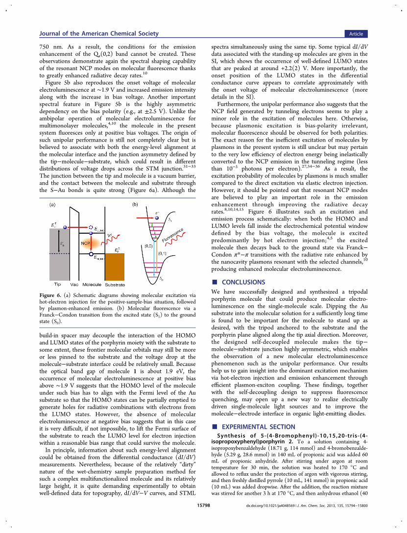
The junction between the tip and molecule is a vacuum barrier,and the contact between the molecule and substrate throughthe S−Au bonds is quite strong (Figure 6a). Although the
build-in spacer may decouple the interaction of the HOMOand LUMO states of the porphyrin moiety with the substrate tosome extent, these frontier molecular orbitals may still be moreor less pinned to the substrate and the voltage drop at themolecule−substrate interface could be relatively small. Becausethe optical band gap of molecule 1 is about 1.9 eV, theoccurrence of molecular electroluminescence at positive biasabove ∼1.9 V suggests that the HOMO level of the moleculeunder such bias has to align with the Fermi level of the Ausubstrate so that the HOMO states can be partially emptied togenerate holes for radiative combinations with electrons fromthe LUMO states. However, the absence of molecularelectroluminescence at negative bias suggests that in this caseit is very difficult, if not impossible, to lift the Fermi surface ofthe substrate to reach the LUMO level for electron injectionwithin a reasonable bias range that could survive the molecule.In principle, information about such energy-level alignment
could be obtained from the differential conductance (dI/dV)measurements. Nevertheless, because of the relatively “dirty”nature of the wet-chemistry sample preparation method forsuch a complex multifunctionalized molecule and its relativelylarge height, it is quite demanding experimentally to obtainwell-defined data for topography, dI/dV−V curves, and STML
spectra simultaneously using the same tip. Some typical dI/dVdata associated with the standing-up molecules are given in theSI, which shows the occurrence of well-defined LUMO statesthat are peaked at around +2.2(2) V. More importantly, theonset position of the LUMO states in the differentialconductance curve appears to correlate approximately withthe onset voltage of molecular electroluminescence (moredetails in the SI).Furthermore, the unipolar performance also suggests that the
NCP field generated by tunneling electrons seems to play aminor role in the excitation of molecules here. Otherwise,because plasmonic excitation is bias-polarity irrelevant,molecular fluorescence should be observed for both polarities.The exact reason for the inefficient excitation of molecules byplasmons in the present system is still unclear but may pertainto the very low efficiency of electron energy being inelasticallyconverted to the NCP emission in the tunneling regime (lessthan 10−3 photons per electron).27,34−36 As a result, theexcitation probability of molecules by plasmons is much smallercompared to the direct excitation via elastic electron injection.However, it should be pointed out that resonant NCP modesare believed to play an important role in the emissionenhancement through improving the radiative decayrates.8,10,14,15 Figure 6 illustrates such an excitation andemission process schematically: when both the HOMO andLUMO levels fall inside the electrochemical potential windowdefined by the bias voltage, the molecule is excitedpredominantly by hot electron injection;4,5 the excitedmolecule then decays back to the ground state via Franck−Condon π*−π transitions with the radiative rate enhanced bythe nanocavity plasmons resonant with the selected channels,10
producing enhanced molecular electroluminescence.
■ CONCLUSIONSWe have successfully designed and synthesized a tripodalporphyrin molecule that could produce molecular electro-luminescence on the single-molecule scale. Dipping the Ausubstrate into the molecular solution for a sufficiently long timeis found to be important for the molecule to stand up asdesired, with the tripod anchored to the substrate and theporphyrin plane aligned along the tip axial direction. Moreover,the designed self-decoupled molecule makes the tip−molecule−substrate junction highly asymmetric, which enablesthe observation of a new molecular electroluminescencephenomenon such as the unipolar performance. Our resultshelp us to gain insight into the dominant excitation mechanismvia hot-electron injection and emission enhancement throughefficient plasmon-exciton coupling. These findings, togetherwith the self-decoupling design to suppress fluorescencequenching, may open up a new way to realize electricallydriven single-molecule light sources and to improve themolecule−electrode interface in organic light-emitting diodes.
■ EXPERIMENTAL SECTIONSynthesis of 5-(4-Bromophenyl)-10,15,20-tris-(4-
isopropoxyphenyl)porphyrin 2. To a solution containing 4-isopropoxybenzaldehyde (18.71 g, 114 mmol) and 4-bromobenzalde-hyde (5.29 g, 28.6 mmol) in 140 mL of propionic acid was added 60mL of propionic anhydride. After stirring under argon at roomtemperature for 30 min, the solution was heated to 170 °C andallowed to reflux under the protection of argon with vigorous stirring,and then freshly distilled pyrrole (10 mL, 141 mmol) in propionic acid(10 mL) was added dropwise. After the addition, the reaction mixturewas stirred for another 3 h at 170 °C, and then anhydrous ethanol (40
Figure 6. (a) Schematic diagrams showing molecular excitation viahot-electron injection for the positive-sample-bias situation, followedby plasmon-enhanced emission. (b) Molecular fluorescence via aFranck−Condon transition from the excited state (S1) to the groundstate (S0).
Journal of the American Chemical Society Article
dx.doi.org/10.1021/ja4048569 | J. Am. Chem. Soc. 2013, 135, 15794−1580015798
mL) was added under vigorous stirring. The mixture was cooled toroom temperature and filtered, and the solid product was washedrepeatedly with ethanol until the rinsing solution was no longer dark.The filter cake was dissolved in CH2Cl2 and chromatographed on silicagel using CH2Cl2−petroleum ether (1/1) as the eluent to affordpurple crystalline porphyrin 2 (1.51 g, 6%). 1H NMR (400 MHz,CDCl3) δ 8.89 (d, J = 4.8 Hz, 2H), 8.88 (s, 4H), 8.78 (d, J = 4.8 Hz,2H), 8.09−8.04 (m, 8H), 7.84 (d, J = 8.2 Hz, 2H), 7.23−7.21 (m,6H), 4.81 (heptet, J = 6.0 Hz, 1H), 4.80 (heptet, J = 6.0 Hz, 2H), 1.53(d, J = 6.0 Hz, 18H), −2.75 (bs, 2H, NH). 13C NMR (100 MHz,CDCl3) δ 157.9, 141.5, 136.0, 135.8, 134.5, 134.4, 130.0, 122.5, 120.5,120.3, 118.1, 114.1, 70.3, 22.5. MALDI-TOF-MS m/z: [M+] calcd forC53H47
79BrN4O3 866.2832, found 866.2059.Synthesis of Zinc(II)-5-(4-bromophenyl)-10,15,20-tris-(4-
isopropoxyphenyl)porphyrin 3. A mixture of 5-(4-bromophen-yl)-10,15,20-tris-(4-isopropoxyphenyl)porphyrin 2 (1.03 g, 1.19mmol) and Zn(OAc)2·2H2O (2.80 g, 12.7 mmol) was dissolved inchloroform−CH3OH (60 mL, 3/1), and then the mixture was allowedto reflux under argon for 5 h. After the removal of the solvents, theresidue was chromatographed on a silica gel column (CH2Cl2−petroleum ether, 1/1) to give porphyrin 3 (1.02 g, 93% yield). 1HNMR (400 MHz, CDCl3) δ 8.99−8.96 (m, 6H), 8.86 (d, J = 4.7 Hz,2H), 8.07−8.02 (m, 8H), 7.81 (d, J = 8.2 Hz, 2H), 7.20−7.16 (m,6H), 4.77 (heptet, J = 6.0 Hz, 1H), 4.76 (heptet, J = 6.0 Hz, 2H), 1.51(d, J = 6.0 Hz, 18H). 13C NMR (100 MHz, CDCl3) δ 157.7, 150.9,150.8, 150.7, 149.9, 142.1, 135.9, 135.6, 135.1, 135.0, 132.4, 132.3,132.2, 131.5, 129.8, 122.2, 121.5, 121.3, 119.2, 114.0, 70.3, 22.5.MALDI-TOF-MS m/z: [M+] calcd for C53H45
79BrN4O3Zn 928.1967,found 928.0060.Synthesis of TMS-Protected Zinc(II)-5-(4-ethynylphenyl)-
10,15,20-tris-(4-isopropoxyphenyl)porphyrin 4. Air was re-moved from a single-necked flask containing a mixture of 3 (433.2mg, 0.47 mmol), Pd(PPh3)2Cl2 (84.1 mg, 0.12 mmol), CuI (46.5 mg,0.24 mmol), and PPh3 (60.0 mg, 0.23 mmol) in THF−Et3N (35 mL,6/1) by argon bubbling for 30 min. Then trimethylsilylacetylene (450μL, 3.19 mmol) was added, and the mixture was allowed to stir underargon at room temperature for 10 min. Thereafter, the flask was sealedand heated at 80 °C for 48 h. After cooling to room temperature, thesolvent was evaporated, and the crude product was purified on a silicagel column (CH2Cl2−petroleum ether, 1/1) to provide TMS-protected porphyrin 4 (308.5 mg, 70% yield). 1H NMR (400 MHz,CDCl3) δ 8.97 (d, J = 4.7 Hz, 2H), 8.96 (s, 4H), 8.86 (d, J = 4.7 Hz,2H), 8.12 (d, J = 8.2 Hz, 2H), 8.054 (d, J = 8.6 Hz, 2H), 8.047 (d, J =8.6 Hz, 4H), 7.85 (d, J = 8.2 Hz, 2H), 7.23 (d, J = 8.6 Hz, 6H), 4.84(heptet, J = 6.0 Hz, 3H), 1.56 (d, J = 6.0 Hz, 18H), 0.38 (s, 9H). 13CNMR (100 MHz, CDCl3) δ 157.8, 150.8, 150.73, 150.68, 149.9, 143.5,135.6, 135.11, 135.07, 134.5, 132.4, 132.2, 132.1, 131.6, 130.4, 122.4,121.4, 121.2, 119.9, 114.0, 105.4, 95.4, 70.3, 22.5, 0.3. MALDI-TOF-MS m/z: [M+] calcd for C58H54N4O3SiZn 946.3257, found 946.2683.Synthesis of Zinc(II)-5-(4-ethynylphenyl)-10,15,20-tris-(4-
isopropoxyphenyl)porphyrin 5. Porphyrin 4 (308.5 mg, 0.33mmol) was dissolved in distilled THF (30 mL) and stirred under anargon atmosphere for 15 min. Then tetrabutylammonium fluoride(1.69 g, 6.48 mmol) was added. The mixture was stirred under argonfor 1 h and then diluted with dichloromethane (100 mL) and washedtwice with water. The organic phase was collected and dried overanhydrous sodium sulfate. The solvent was removed under reducedpressure, and the crude product was purified on a silica gel column(CH2Cl2−petroleum ether, 1/1) to yield porphyrin 5 (235.0 mg, 82%yield). 1H NMR (400 MHz, CDCl3) δ 9.00 (d, J = 4.7 Hz, 2H), 8.99(s, 4H), 8.90 (d, J = 4.7 Hz, 2H), 8.18 (d, J = 8.2 Hz, 2H), 8.10 (d, J =8.5 Hz, 2H), 8.09 (d, J = 8.5 Hz, 4H), 7.88 (d, J = 8.2 Hz, 2H), 7.25(d, J = 8.4 Hz, 6H), 4.86 (heptet, J = 6.0 Hz, 3H), 3.30 (s, 1H), 1.57(d, J = 6.0 Hz, 18H). 13C NMR (100 MHz, CDCl3) δ 157.8, 150.9,150.74, 150.68, 149.9, 143.8, 135.6, 135.1, 135.0, 134.5, 132.4, 132.24,132.16, 131.6, 130.5, 121.5, 121.4, 121.3, 119.8, 114.0, 84.0, 78.2, 70.3,22.5. MALDI-TOF-MS m/z: [M+] calcd for C55H46N4O3Zn 874.2861,found 874.2104.Synthesis of Porphyrin 6. A solution of porphyrin 5 (219.8 mg,
0.25 mmol) and 1-(4-iodophenyl)-1,1,1-tris[4-(S-acetylthiomethyl)-
phenyl]methane (268.7 mg, 0.38 mmol) in dry toluene−triethylamine(18 mL, 5/1) was purged with argon for 30 min. The coupling wasinitiated by adding PPh3 (113.0 mg, 0.43 mmol) followed byPd2(dba)3 (114.5 mg, 0.13 mmol), and the reaction mixture wasthen stirred at 30 °C for 7 days until thin-layer chromatography(TLC) monitoring indicated the formation of new spots and thedisappearance of 5. The crude reaction mixture was purified by silicagel chromatography using petroleum ether/dichloromethane (1/2) asthe eluent to furnish porphyrin 6 (230.7 mg, 63% yield). 1H NMR(400 MHz, CDCl3) δ 8.99 (d, J = 4.6 Hz, 2H), 8.98 (s, 4H), 8.92 (d, J= 4.6 Hz, 2H), 8.18 (d, J = 8.1 Hz, 2H), 8.08 (d, J = 8.4 Hz, 6H), 7.88(d, J = 8.1 Hz, 2H), 7.54 (d, J = 8.5 Hz, 2H), 7.24−7.21 (m, 6H),7.15−7.03 (m, 14H), 4.88−4.79 (m, 3H), 3.96 (s, 6H), 2.21 (s, 9H),1.55 (d, J = 6.0 Hz, 18H). 13C NMR (100 MHz, CDCl3) δ 195.3 (CO), 157.7, 150.8, 150.7, 150.6, 149.9, 147.1, 145.4, 143.3, 143.2, 135.6,135.4, 135.13, 135.10, 134.6, 132.3, 132.2, 132.1, 131.6, 131.3, 131.2,131.1, 130.0, 129.0, 128.9, 128.4, 128.2, 127.4, 122.5, 121.3, 121.1,119.9, 114.0, 90.3, 89.8, 70.3, 64.4, 33.0, 30.3, 22.5. MALDI-TOF-MSm/z: [M+] calcd for C89H76N4O6S3Zn 1456.4218, found 1456.4545.
Synthesis of Porphyrin 1. Porphyrin 6 (43.2 mg, 0.03 mmol) wasplaced in a 250 mL three-necked round-bottomed flask and dissolvedwith degassed CH2Cl2 (56 mL) and degassed MeOH (28 mL).Concentrated H2SO4 (5.6 mL) was added dropwise to the mixture at 0°C. The mixture was then gradually warmed to 60 °C with stirring.After stirring for 12 h, the reaction was quenched by the addition ofwater, and the organic layer was separated. The aqueous layer wasextracted with CH2Cl2, and the combined organic layer was washedwith brine and dried over Na2SO4. After the removal of the solventunder reduced pressure, the residue was purified by columnchromatography on silica gel with CH2Cl2 as the eluent to give targetmolecule 1 (31.6 mg, 84% yield). 1H NMR (400 MHz, CDCl3) δ 8.90(d, J = 4.8 Hz, 2H), 8.89 (s, 4H), 8.83 (d, J = 4.8 Hz, 2H), 8.19 (d, J =8.1 Hz, 2H), 8.09 (d, J = 8.4, 6H), 7.89 (d, J = 8.0 Hz, 2H), 7.56 (d, J= 8.4 Hz, 2H), 7.29−7.19 (m, 20H), 4.85 (heptet, J = 6.1 Hz, 3H),3.74 (d, J = 7.5 Hz, 6H), 1.79 (t, J = 7.5 Hz, 3H), 1.56 (d, J = 6.1 Hz,18H), −2.74 (bs, 2H, NH). 13C NMR (100 MHz, CDCl3) δ 157.9,147.3, 145.33, 145.27, 142.6, 139.0, 135.9, 134.8, 134.5, 134.4, 131.4,131.23, 131.18, 130.1, 127.5, 122.8, 121.1, 120.5, 120.2, 118.9, 114.1,90.5, 89.8, 70.3, 64.5, 28.6, 22.5. ESI-MS m/z: [M + H+] calcd forC83H72N4O3S3 1268.4767, found 1269.4840.
Theoretical Calculation. The geometry of 1 was calculated at theB3LYP/6-31G(d) level with Gaussian 09W without a consideration ofthe effect of the substrate.
Acquisition of Photoluminescence Spectra and Measure-ment of Photoluminescence Lifetimes. The acquisition of PLspectra and the measurement of fluorescence lifetimes were carried outon a home-built optical setup. Steady-state spectra were recorded witha liquid-nitrogen-cooled charge-coupled-device (CCD) spectrometer(Princeton Instruments) under the excitation of light at 405 nm. Thetime-correlated single-photon counting technique (Edinburgh Instru-ments) was used to determine the fluorescence lifetimes. The timeresolution was ∼8 ps with the use of a microchannel platephotomultiplier tube and a pulse picosecond diode laser at 405 nm(Hamamatsu). A cutoff filter at 470 nm was used to block theexcitation light. The time-resolved PL curves were fitted with anexponential function.
Molecular Deposition on Au(111). After being synthesized andpurified, molecule 1 was immediately dissolved in CH2Cl2 at aconcentration of ∼1.0 × 10⁻⁶ M.
Wet-Chemistry Method via Short-Time Drop-Casting. The drop-casted sample was prepared by dripping 10 μL of a solution of 1 ontothe atomically cleaned Au(111) surface in the load-lock chamberunder a nitrogen-gas atmosphere. The solvent evaporated withinseconds, and the chamber was immediately pumped under vacuum.The sample was then transferred to the ultrahigh-vacuum (UHV)observation chamber for STM investigations at low temperature (∼80K).
Wet-Chemistry Method via Long-Time Immersion. The freshlyprepared Au(111) substrate was immersed in the solution for 10 h atroom temperature. Then the substrate was removed from the solution,
Journal of the American Chemical Society Article
dx.doi.org/10.1021/ja4048569 | J. Am. Chem. Soc. 2013, 135, 15794−1580015799
rinsed thoroughly with CH2Cl2 10 times, and dried under a stream ofnitrogen gas before being loaded into the UHV chamber for STMinvestigations at low temperature (∼80 K). The influence ofconcentration and immersion time on the adsorption configurationof the target molecule on Au is briefly described in the SI.Scanning Tunneling Microscope-Induced Luminescence.
The experiments were performed with a low-temperature UHV-STM (Unisoku) at a base pressure of ∼8 × 10⁻¹¹ mbar at ∼80 K,operated in the constant-current−topographic mode with the samplebiased. The Au(111) substrate was prepared by the thermalevaporation of gold (∼150 nm thick) on freshly cleaved mica andcleaned in UHV by cycles of argon ion sputtering. Electrochemicallyetched silver (Ag) tips were used to perform STM imaging and STMLmeasurements, taking advantage of silver in producing strongplasmonic fields.35
Photons emitted from the tunnel junction were collected with a lensinside the UHV chamber and then refocused into an optical fiber byanother lens placed outside the UHV chamber. The collected light wasguided into a grating spectrometer and analyzed by a cooled CCDdetector (Princeton Instruments) for spectral information.10,35,36
Photon intensities, measured by the SPAD (PerkinElmer, ∼72%detection efficiency of around 660 nm), were corrected for thedetection efficiency of the SPAD and the collection efficiency of boththe lens system (∼10%) and the beamsplitter (50%).36 Nevertheless,luminescence spectra presented in the article were not corrected forthe wavelength-dependent sensitivity of photon collection anddetection systems.
■ ASSOCIATED CONTENT*S Supporting InformationExperimental procedures for the synthesis of Tpd-I, thermog-ravimetric analysis, additional STM and tunneling spectralinformation, Cartesian coordinates of molecule 1, and NMRspectra of synthesized compounds. This material is availablefree of charge via the Internet at http://pubs.acs.org.
■ AUTHOR INFORMATIONCorresponding [email protected]@ustc.edu.cnAuthor ContributionsS.-E.Z. and Y.-M.K. contributed equally.NotesThe authors declare no competing financial interest.
■ ACKNOWLEDGMENTSWe thank Andre Gourdon for helpful discussions on themolecular design. This work is supported by NBRPC(2011CB921402), CAS (XDB01020000), and NSFC(91021004 and 10974186).
■ REFERENCES(1) Coombs, J. H.; Gimzewski, J. K.; Reihl, B.; Sass, J. K.; Schlittler,R. R. J. Microsc. 1988, 152, 325.(2) Berndt, R.; Gaisch, R.; Gimzewski, J. K.; Reihl, B.; Schlittler, R.R.; Schneider, W. D.; Tschudy, M. Science 1993, 262, 1425.(3) Qiu, X. H.; Nazin, G. V.; Ho, W. Science 2003, 299, 542.(4) Dong, Z. C.; Guo, X. L.; Trifonov, A. S.; Dorozhkin, P. S.; Miki,K.; Kimura, K.; Yokoyama, S.; Mashiko, S. Phys. Rev. Lett. 2004, 92,086801.(5) Cavar, E.; Blum, M.-C.; Pivetta, M.; Patthey, F.; Chergui, M.;Schneider, W.-D. Phys. Rev. Lett. 2005, 95, 196102.(6) Chance, R. R.; Prock, A.; Silbey, R. Adv. Chem. Phys. 1978, 37, 1.(7) Barnes, W. L. J. Mod. Opt. 1998, 45, 661.(8) Anger, P.; Bharadwaj, P.; Novotny, L. Phys. Rev. Lett. 2006, 96,113002.
(9) Zhang, X.-L.; Chen, L.-G.; Lv, P.; Gao, H.-Y.; Wei, S.-J.; Dong,Z.-C.; Hou, J. G. Appl. Phys. Lett. 2008, 92, 223118.(10) Dong, Z. C.; Zhang, X. L.; Gao, H. Y.; Luo, Y.; Zhang, C.; Chen,L. G.; Zhang, R.; Tao, X.; Zhang, Y.; Yang, J. L.; Hou, J. G. Nat.Photonics 2010, 4, 50.(11) Kabakchiev, A.; Kuhnke, K.; Lutz, T.; Kern, K. Chem. Phys.Chem. 2010, 11, 3412.(12) Matino, F.; Schull, G.; Kohler, F.; Gabutti, S.; Mayor, M.;Berndt, R. Proc. Natl. Acad. Sci. U.S.A. 2011, 108, 961.(13) Schneider, N. L.; Matino, F.; Schull, G.; Gabutti, S.; Mayor, M.;Berndt, R. Phys. Rev. B 2011, 84, 153403.(14) Mills, D. L. Phys. Rev. B 2002, 65, 125419.(15) Kuhn, S.; Mori, G.; Agio, M.; Sandoghdar, V. Mol. Phys. 2008,106, 893.(16) Milgrom, L. R. The Colour of Life: An Introduction to theChemistry of Porphyrin and Related Compounds; Oxford UniversityPress: New York, 1997.(17) Davis, G. L.; Hey, D. Y.; Williams, G. H. J. Chem. Soc. 1956,4397.(18) Heim, C.; Affeld, A.; Nieger, M.; Vogtle, F. Helv. Chim. Acta1999, 82, 746.(19) Zhu, L.; Tang, H.; Harima, Y.; Yamashita, K.; Hirayama, D.;Aso, Y.; Otsubo, T. Chem. Commun. 2001, 1830.(20) Hirayama, D.; Takimiya, K.; Aso, Y.; Otsubo, T.; Hasobe, T.;Yamada, H.; Imahori, H.; Fukuzumi, S.; Sakata, Y. J. Am. Chem. Soc.2002, 124, 532.(21) Wei, L.; Padmaja, K.; Youngblood, W. J.; Lysenko, A. B.;Lindsey, J. S.; Bocian, D. F. J. Org. Chem. 2004, 69, 1461.(22) Sakata, T.; Maruyama, S.; Ueda, A.; Otsuka, H.; Miyahara, Y.Langmuir 2007, 23, 2269.(23) Ie, Y.; Hirose, T.; Yao, A.; Yamada, T.; Takagi, N.; Kawai, M.;Aso, Y. Phys. Chem. Chem. Phys. 2009, 11, 4949.(24) Adler, A. D.; Longo, F. R.; Finarelli, J. D.; Goldmacher, J.;Assour, J.; Korsakoff, L. J. Org. Chem. 1967, 32, 476.(25) Schramm, A.; Stroh, C.; Dossel, K.; Lukas, M.; Fischer, M.;Schramm, F.; Fuhr, O.; v. Lohneysen, H.; Mayor, M. Eur. J. Inorg.Chem. 2013, 2013, 70.(26) Jung, T. A.; Schlittler, R. R.; Gimzewski, J. K. Nature 1997, 386,696.(27) Berndt, R.; Gimzewski, J. K.; Johansson, P. Phys. Rev. Lett. 1991,67, 3796.(28) Tao, X.; Dong, Z. C.; Yang, J. L.; Luo, Y.; Hou, J. G.; Aizpurua,J. J. Chem. Phys. 2009, 130, 084706.(29) Zhang, Y.; Geng, F.; Gao, H. Y.; Liao, Y.; Dong, Z. C.; Hou, J.G. Appl. Phys. Lett. 2010, 97, 243101.(30) Geng, F.; Zhang, Y.; Yu, Y.; Kuang, Y.; Liao, Y.; Dong, Z.; Hou,J. Opt. Express 2012, 20, 26725.(31) Zahid, F.; Paulsson, M.; Datta, S. Electrical Conduction throughMolecules. In Advanced Semiconductors and Organic Nano-Techniques;Morkoc, H., Ed.; Academic Press: New York, 2003; Vol. III, pp 1−41.(32) Wu, S. W.; Nazin, G. V.; Chen, X.; Qiu, H. X.; Ho, W. Phys. Rev.Lett. 2004, 93, 236802.(33) Niquet, Y. M.; Delerue, C.; Allan, G. Phys. Rev. B 2002, 65,165334.(34) Johansson, P. Phys. Rev. B 1998, 58, 10823.(35) Zhang, C.; Gao, B.; Chen, L. G.; Meng, Q. S.; Yang, H.; Zhang,R.; Tao, X.; Gao, H. Y.; Liao, Y.; Dong, Z. C. Rev. Sci. Instrum. 2011,82, 083101.(36) Chen, L. G.; Zhang, C.; Zhang, R.; Zhang, X. L.; Dong, Z. C.Rev. Sci. Instrum. 2013, 84, 066106.
Journal of the American Chemical Society Article
dx.doi.org/10.1021/ja4048569 | J. Am. Chem. Soc. 2013, 135, 15794−1580015800