Embed Size (px)
Citation preview
Heriot-Watt University Research Gateway
Self-centering steel column base with metallic energy dissipationdevices
Citation for published version:Kamperidis, VC, Karavasilis, TL & Vasdravellis, G 2018, 'Self-centering steel column base with metallicenergy dissipation devices', Journal of Constructional Steel Research, vol. 149, pp. 14-30.https://doi.org/10.1016/j.jcsr.2018.06.027
Digital Object Identifier (DOI):10.1016/j.jcsr.2018.06.027
Link:Link to publication record in Heriot-Watt Research Portal
Document Version:Peer reviewed version
Published In:Journal of Constructional Steel Research
General rightsCopyright for the publications made accessible via Heriot-Watt Research Portal is retained by the author(s) and /or other copyright owners and it is a condition of accessing these publications that users recognise and abide bythe legal requirements associated with these rights.
Take down policyHeriot-Watt University has made every reasonable effort to ensure that the content in Heriot-Watt ResearchPortal complies with UK legislation. If you believe that the public display of this file breaches copyright pleasecontact [email protected] providing details, and we will remove access to the work immediately andinvestigate your claim.
Download date: 21. Jan. 2022
1
Self-centering steel column base with metallic
energy dissipation devices
Vasileios C. Kamperidisa1*, Theodore L. Karavasilisb2 and George Vasdravellisc3
a School of Engineering, University of Warwick, Coventry, CV4 7AL, United Kingdom
b Faculty of Engineering and the Environment, University of Southampton, Highfield Southampton, SO17
1BJ, United Kingdom
c Institute for Infrastructure and Environment, Heriot-Watt University, Edinburgh, EH14 4AS, United Kingdom
ABSTRACT
Column bases of seismic-resistant steel frames are typically designed as full-strength to ensure that plastic
hinges develop in the bottom end of the first-storey columns. Alternatively, column bases may be
designed as partial-strength and dissipate energy through inelastic deformations in their main components
(i.e., base plate, steel anchor rods). Both design philosophies result in difficult-to-repair damage and
residual drifts. Moreover, the second design philosophy results in complex hysteretic behaviour with
strength and stiffness deterioration. This paper proposes a partial-strength low-damage self-centering
steel column base. The column base provides flexibility in the design as its rotational stiffness and
moment resistance can be independently tuned. The paper presents an analytical model that predicts the
stiffness, strength, and hysteretic behaviour of the column base. In addition, a design procedure and
detailed finite element models are presented. The paper evaluates the effectiveness of the column base by
carrying out nonlinear dynamic analyses on a prototype steel building designed as post-tensioned self-
centering moment-resisting frame. The results demonstrate the potential of the column base to reduce the
residual first-storey drifts and protect the first-storey columns from yielding.
Keywords: column base; self-centering; low-damage; post-tensioned; seismic resilience; rocking.
1* Corresponding author, Ph.D., E-mail: [email protected], ORCID ID number: 0000-0003-4893-7110 2 Professor of Structures and Structural Mechanics, E-mail: [email protected] Assistant Professor, E-mail: [email protected]
2
1 Introduction
Column bases are fundamental components of a seismic-resistant steel frame. Their rotational
stiffness and moment resistance affect the storey drifts, the forces in the structural members, and
the collapse resistance of a steel building [1–5]. Within the capacity design philosophy of EC8
[6], column bases are typically designed as full-strength joints [7] to ensure the formation of a
plastic hinge within the bottom end of the column rather than in the column base [6].
Alternatively, column bases may be designed as partial-strength joints and dissipate energy
through inelastic deformations in their main components (i.e., base plate, anchor rods). Both
design philosophies result in difficult-to-repair damage and residual drifts. Moreover, the second
design philosophy results in complex hysteretic behaviour with strength and stiffness
deterioration. In terms of their rotational stiffness, column bases are in practice modelled as rigid
or pinned, which rely on assumptions that do not accurately represent their actual behaviour.
Such assumptions may either underestimate or overestimate the storey drifts and internal
member forces, thus leading to designs that may be uneconomical or unsafe [2,3,5].
A number of research efforts exist on the development of column bases with self-centering
and low-damage characteristics. Among the proposed column bases [4,8–18], a promising class
are the post-tensioned (PT) column bases with energy dissipating devices. These column bases
use PT tendons to clamp the column to the foundation and provide self-centering capability, and
devices to dissipate seismic energy along with offering supplemental stiffness and strength.
Previous studies on PT column bases demonstrated their ability to reduce residual storey drifts
[4,14,17,19]. Ikenaga et al. [17,20] proposed a PT column base with yielding devices, which
achieved self-centering capability under a certain level of rotation. However, the self-centering
capability of the column base was restricted by the applicable length and plan view arrangement
of the PT bars, which were placed within the perimeter of their wide flange column foot section.
Under large rotations, tests showed residual rotations in the column base. Chou and Chen [4]
3
proposed a PT column base equipped with reduced flange plates used as yielding devices. PT
bars, running along the length of the steel-concrete composite columns, were used to provide
self-centering capability to the column bases. Their analyses showed that both the frame and PT
column bases had small residual drifts under both the design and maximum considered
earthquakes. Moreover, test results showed that post-tensioning the whole columns resulted in
undesirable column axial shortening [21]. Chi and Liu [14] proposed a column base, which had
conceptual similarities with the column base of Ikenaga et al. [17,20], but with longer tendons.
Thus, their column base could achieve self-centering behaviour under larger rotations. However,
the column base could not avoid loss of post-tensioning due to the large PT forces applied to the
column foot. Tests also showed that some parts of the column base experienced undesirable
plastic deformations. Recently, Chen et al. [18] proposed a self-centering column base with
friction devices. Their column base achieved self-centering behaviour for large rotations. Yet,
the column base could not avoid column axial shortening and worked only with open column
sections.
This paper presents a partial-strength low-damage self-centering steel column base that uses
PT tendons to achieve self-centering behaviour and hourglass shape steel yielding devices,
referred to as web hourglass pins (WHPs) [22], to dissipate seismic energy. The WHPs are
installed in a way that makes their post-earthquake replacement straightforward. The rotational
stiffness and moment resistance of the column base can be independently tuned. Self-centering
behaviour can be ensured even under very large base rotations by adjusting the position and
characteristics of the tendons and WHPs. The PT tendons are anchored on the top of a strong
column foot. The column foot receives the large PT forces instead of the column, increasing the
rotation capacity of the latter and avoiding column axial shortening and loss of post-tensioning.
Anchoring the PT tendons on the column foot avoids difficulties in structural detailing (i.e.,
congestion of structural components) at the first-storey beam-column connection. The column
4
base can work both with open steel as well as with steel and steel-concrete composite tubular
sections and can dissipate seismic energy in both the strong and weak axis of the column. Lately,
based on preliminary findings presented in [23], Freddi et al. [24] proposed a column base similar
to the one proposed herein, but with friction EDs, a different mechanism to resist base shear, and
a different column foot. The following sections present an analytical model that predicts the
strength, stiffness and hysteretic behaviour of the PT column base with WHPs, a design
procedure that sizes all its components for a target column base rotation, and nonlinear finite
element method (FEM) models in the software Abaqus [25] and software OpenSees [26]. The
latter model is used in the assessment of a steel building using the column base.
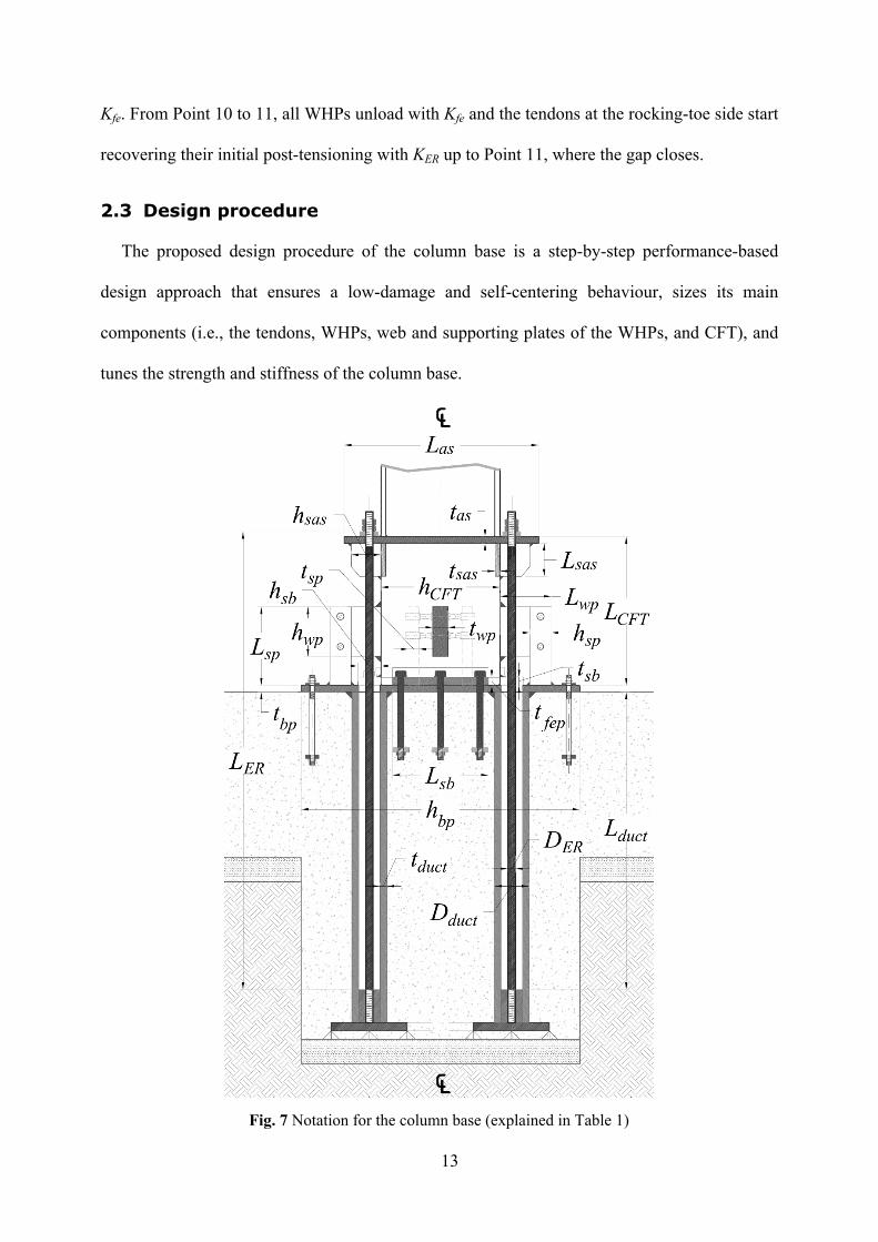
2 Description of the proposed column base
2.1 Structural details and concept development
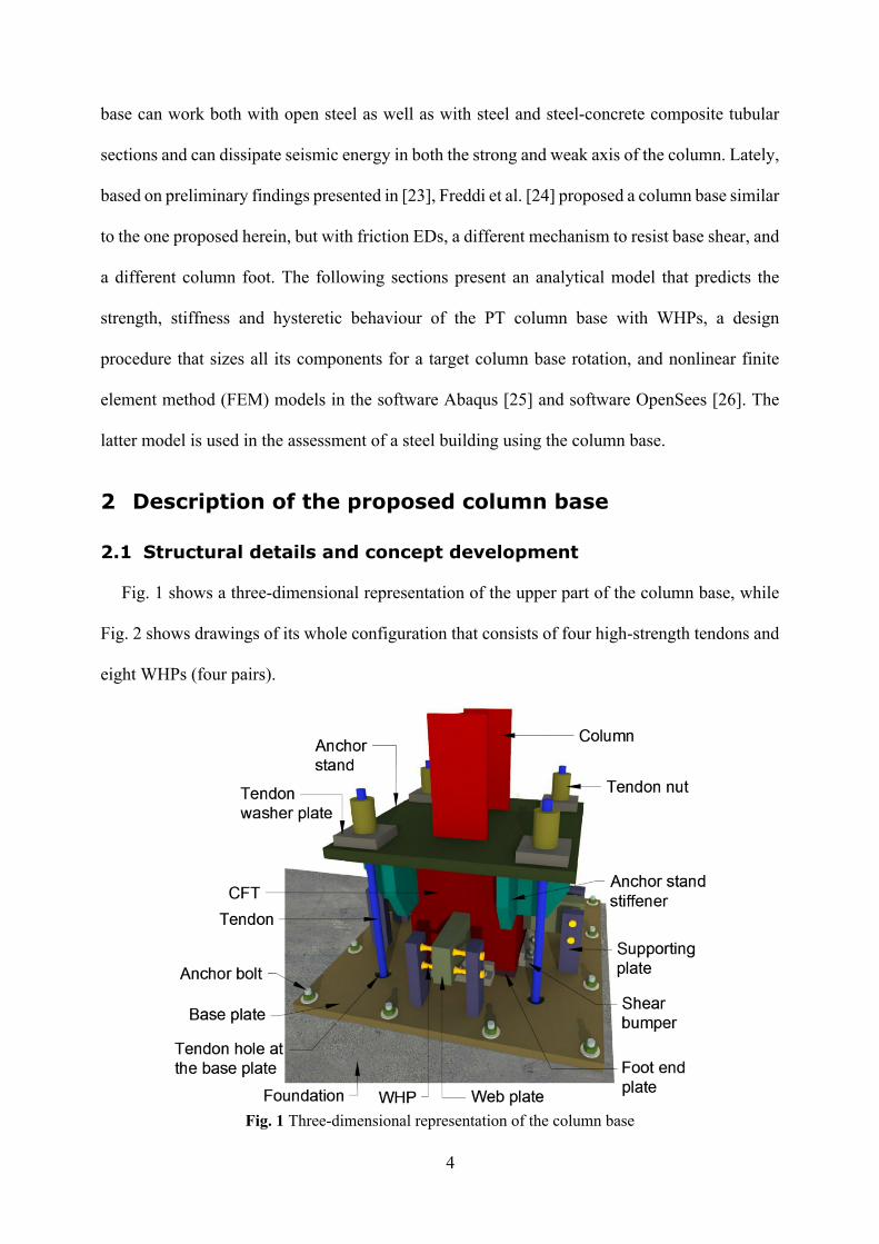
Fig. 1 shows a three-dimensional representation of the upper part of the column base, while
Fig. 2 shows drawings of its whole configuration that consists of four high-strength tendons and
eight WHPs (four pairs).
Fig. 1 Three-dimensional representation of the column base
5
The column is welded on an elevated strong steel plate, or anchor stand, which is, in turn, welded
on a concrete filled steel tube (CFT) that serves as the column foot. The tendons are anchored
on the anchor stand (Detail 1 of Fig. 2(a)) and to the bottom of the concrete foundation, running
unbonded through steel ducts (Fig. 2(a)). The tendons are post-tensioned and clamp the CFT to
a base plate, providing rotational stiffness, moment resistance and self-centering capability.
Concepts with unbonded PT tendons were also used in the past in PT concrete [27–29] and PT
steel-concrete composite columns [4,30,31]. In the aforementioned research, the tendons were
running along the whole height of their host elements, loading them with their large PT forces.
On the contrary, the tendons on the proposed column base are placed within the concrete
foundation and exert their PT forces only on the CFT. As such, the CFT resists the PT forces
instead of the column and thus the latter can avoid the undesirable axial shortening associated
with the increased axial loading from the PT forces, as it was showed in [21]. According to
Garlock et al. [32], preventing the axial shortening of a member associated with a PT connection
can protect the tendons of the connection from loss of their post-tensioning force. As it is shown
next in this research (Section 3.3), this finding can be extended in the proposed column base.
Furthermore, avoiding to receive the large PT forces, the column achieves an increased rotation
capacity [33]. Using the CFT as a column foot helps the column base to form a strong rocking
interface and thus enhance its self-centering and low-damage attributes [34].
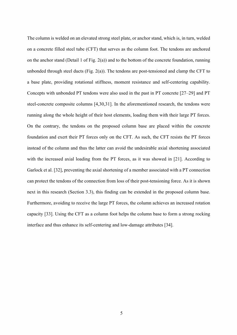
6
(a)
(b) (c)Fig. 2 Drawings of the column base: (a) Vertical cross-section A-A; (b) Elevation 1; (c) Horizontal
cross-section B-B
7
The anchor stand offers flexibility in the arrangement of the tendons, and thus, in the selection
of their lever arms; the latter are defined as the horizontal distances of the tendons from the centre
of rotation (COR) of the column base (Fig. 4). Therefore, the column base can control its stiffness
and strength over its two axes. The anchor stand is reinforced with stiffeners to avoid excessive
bending due to the large PT forces, protecting the tendons from loss of post-tensioning. The
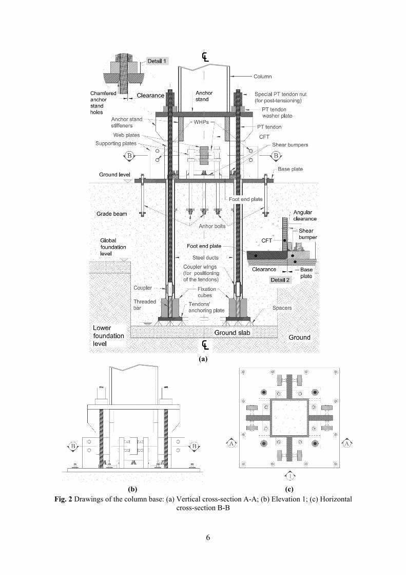
WHPs are inserted in aligned holes drilled on vertical plates, named supporting plates, and on
horizontal plates, named web plates. The supporting plates are welded on the base plate, while
the web plates on the four sides of the CFT (Fig. 1). The WHPs possess high fracture capacity
due to their optimized shape (Fig. 3(a)) and provide repeatable and consistent energy dissipation
through inelastic bending [35]. Except for the WHPs, the column base solely uses steel plated
elements to avoid additional fabrication and machinery costs.
(a)
(b)Fig. 3 (a) Photo of a single WHP; (b) notation and geometry of the supporting plate-web plate-WHP
system (plan view)
8
Shear is resisted through friction in the rocking interface and through steel elements bolted on
the base plate against the four sides of the CFT, named shear bumpers (Detail 2 in Fig. 2(a)).
The shear bumpers are detailed to avoid interlocking during the CFT rocking. The proposed
column base can resist seismic loading and dissipate seismic energy in both loading axes by
appropriately selecting the lever arms and characteristics of the PT tendons and WHPs. However,
this research investigates the case of uniaxial seismic loading.
2.2 Moment-rotation behaviour
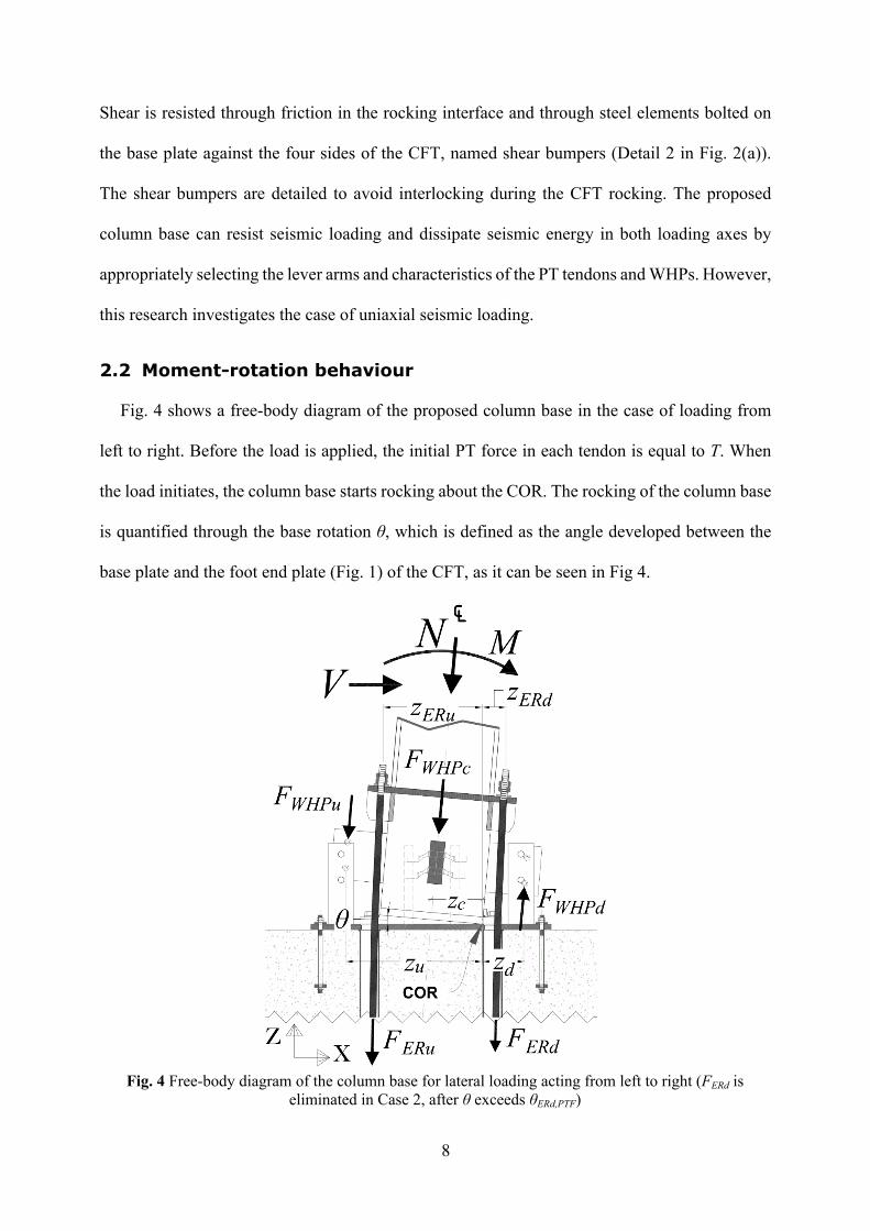
Fig. 4 shows a free-body diagram of the proposed column base in the case of loading from
left to right. Before the load is applied, the initial PT force in each tendon is equal to T. When
the load initiates, the column base starts rocking about the COR. The rocking of the column base
is quantified through the base rotation θ, which is defined as the angle developed between the
base plate and the foot end plate (Fig. 1) of the CFT, as it can be seen in Fig 4.
Fig. 4 Free-body diagram of the column base for lateral loading acting from left to right (FERd is eliminated in Case 2, after θ exceeds θERd,PTF)
9
The COR is assumed to be at the rocking toe (right leaning edge in Fig. 4) of the foot end plate.
The rocking of the column base causes the left side of the anchor stand to move upwards (gap-
opening side), elongating the left tendons, and the right side to move downwards (rocking-toe
side), reducing the initial PT force in the right tendons. However, the latter tendons do not buckle
because they lack underside nuts and avoid contact with the appropriately detailed oversized
anchor stand holes, as it can be seen in Detail 1 of Fig. 2(a). The total force in the tendons at the
gap-opening side is denoted as FERu and at the rocking-toe side as FERd. The lever arms of the
forces FERu and FERd are zERu and zERd, respectively (Fig. 4).
Rocking of the column base causes also the WHPs to deform and develop forces. In Fig. 4,
the force developed in the WHPs at the gap-opening side is denoted as FWHPu, the force in the
central WHPs (centreline of the column) as FWHPc, and the force in the WHPs at the rocking-toe
side as FWHPd. The lever arms of these forces with respect to the COR are denoted as zu, zc, and
zd, respectively. The latter distances are defined as the horizontal distances between the COR
and the geometric centre of each of the above three WHP groups.
N, M and V are the internal axial force, bending moment and shear force at the bottom of the
column. The total moment resistance of the column base, M, is given by:
(1)N WHP ERM M M M
where MN, MWHP, and MER are the moment contributions of N, WHPs, and tendons, respectively.
Two behaviour cases are identified. In the first case, referred to as Case 1, the tendons at the
rocking-toe side do not lose their post-tensioning up to the target base rotation, θt, and thus the
forces in the column base are those of Fig. 4. In the second case, referred to as Case 2, complete
loss of post-tensioning takes place before θt is reached. The complete loss of post-tensioning in
the tendons at the rocking-toe side is represented by the base rotation θERd,PTF, described in Step
10
2 of the design procedure presented below (Section 2.3). After θERd,PTF is reached, FERd in Fig. 4
is eliminated. Based on the above, Case 1 is expressed as θt < θERd,PTF and Case 2 as θERd,PTF <
θt. In both cases, for the column base to achieve a self-centering behaviour up to θt, the tendons
must avoid yielding under latter rotation. This concept was also used by previous research in PT
column bases with energy dissipation devices [4,14,18]. To avoid yielding, the tendons are
designed according to Step 2 of the design procedure in Section 2.3.
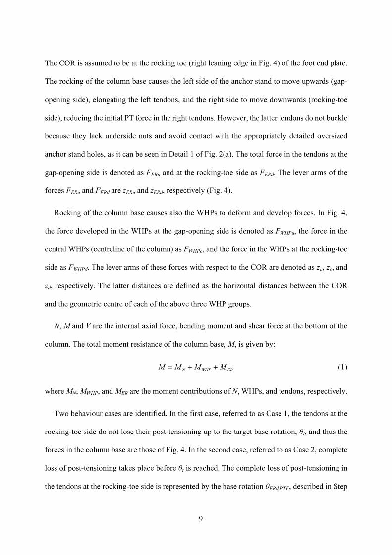
Case 1
Fig. 5(a) shows the theoretical cyclic moment-base rotation (M-θ) behaviour of the column
base for Case 1. After decompression (Point 1 in Fig. 5(a)), gap opens and the behaviour of the
column base becomes nonlinear elastic with rotational stiffness S12.
(a) (b)
(c) (d)Fig. 5 (a) Theoretical cyclic M-θ behaviour of the column base in Case 1; (b) moment contribution
of N; (c) moment contribution of the WHPs; (d) moment contribution of the PT tendons
11
At Point 2, the WHPs at the gap-opening side yield and M continues to increase with slope S23.
At Point 3, the central WHPs yield and M continues to increase with slope S34. At point 4, the
WHPs at the rocking-toe side yield and M continues to increase with slope S45 up to Point 5,
corresponding to θt which is represented by rotation θ5. Upon loading reversal, the column base
begins to unload until the gap closes. Equations to calculate S12, S23, S34, S45, θ2, θ3, θ4, and θ5 are
provided in Section 2.3, while equations for θ6, θ7, and θ8, in Section 2.4. SWHP,12, SWHP,23, SWHP,34
and SWHP,45 are the values of the rotational stiffness in the respective branches of the MWHP-θ
diagram (Fig. 5(c)), while SER,15 is the rotational stiffness of the MER-θ diagram (Fig. 5(d)).
The MWHP-θ behaviour is considered multi-linear elastoplastic. When loading is reversed, all
the WHPs and tendons at the gap-opening side unload with their elastic stiffness up to Point 6,
while each tendon at the rocking-toe side recovers a part of its initial post-tensioning with its
elastic stiffness, KER (defined in Step 2 of Section 2.3). The tendons at the gap-opening side
continue to unload with the same KER until the gap closes, where they finally recover their initial
post-tensioning since they do not yield. Post-tensioning in the tendons at the rocking-toe side
continues to increase until it is fully recovered at gap closing. From Point 6 to 7, each WHP at
the gap-opening side unloads with its post-elastic stiffness, Kfp, while the central and the WHPs
at the rocking-toe side unload with their elastic stiffness, Kfe. From Point 7 to 8, both the central
and the WHPs at the gap-opening side unload with Kfp, while only the WHPs at the rocking-toe
side continue to unload with Kfe. From Point 8 to 9, all WHPs unload with Kfp. Due to the small
values of θ, MN is assumed to be of constant magnitude (Fig. 5(b)) and no negative stiffness is
considered due to rocking [36]. Kfe and Kfp are defined in Step 3 and 4 of Section 2.3,
respectively.
Case 2
Fig. 6(a) shows the theoretical cyclic M-θ behaviour of the column base in Case 2. Case 2
follows the same procedure with Case 1 up to Point 5, where the tendons at the rocking-toe side
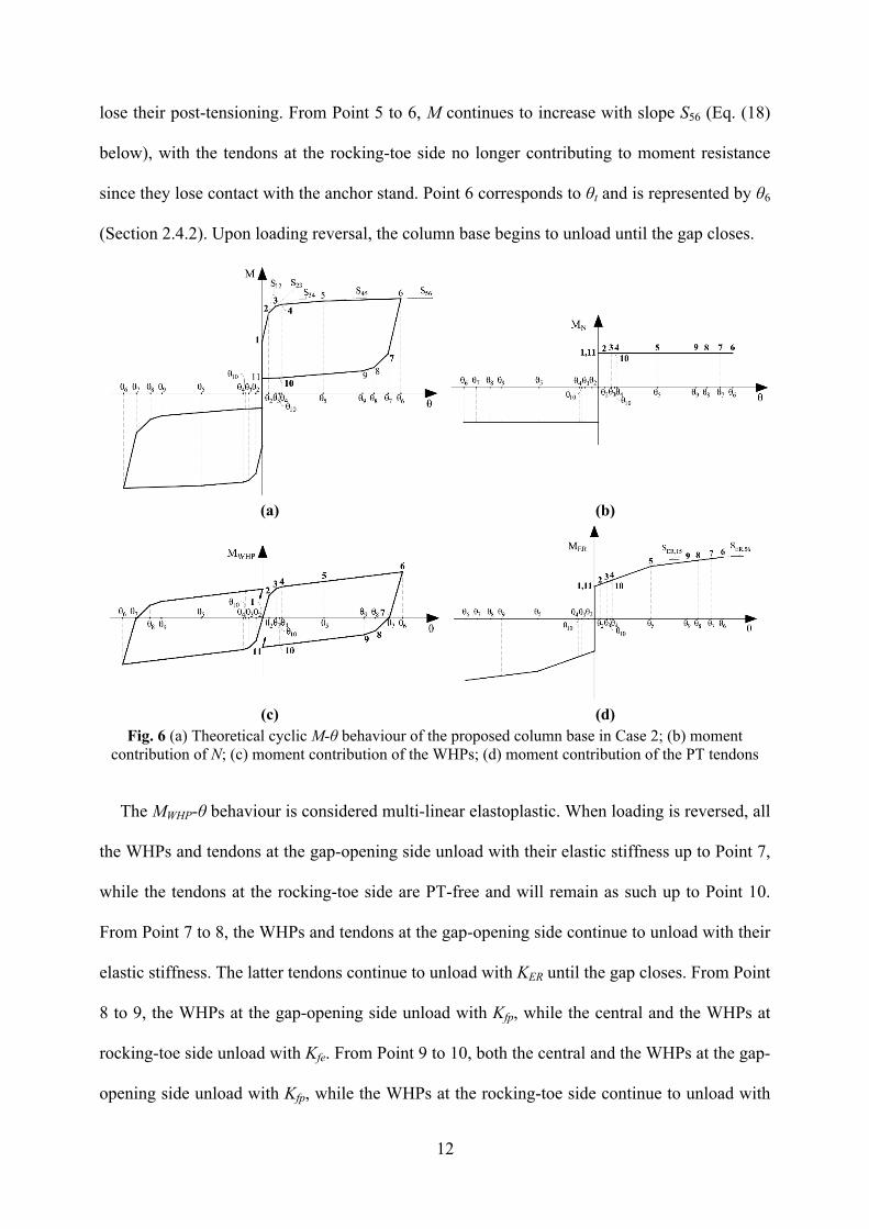
12
lose their post-tensioning. From Point 5 to 6, M continues to increase with slope S56 (Eq. (18)
below), with the tendons at the rocking-toe side no longer contributing to moment resistance
since they lose contact with the anchor stand. Point 6 corresponds to θt and is represented by θ6
(Section 2.4.2). Upon loading reversal, the column base begins to unload until the gap closes.
(a) (b)
(c) (d)Fig. 6 (a) Theoretical cyclic M-θ behaviour of the proposed column base in Case 2; (b) moment
contribution of N; (c) moment contribution of the WHPs; (d) moment contribution of the PT tendons
The MWHP-θ behaviour is considered multi-linear elastoplastic. When loading is reversed, all
the WHPs and tendons at the gap-opening side unload with their elastic stiffness up to Point 7,
while the tendons at the rocking-toe side are PT-free and will remain as such up to Point 10.
From Point 7 to 8, the WHPs and tendons at the gap-opening side continue to unload with their
elastic stiffness. The latter tendons continue to unload with KER until the gap closes. From Point
8 to 9, the WHPs at the gap-opening side unload with Kfp, while the central and the WHPs at
rocking-toe side unload with Kfe. From Point 9 to 10, both the central and the WHPs at the gap-
opening side unload with Kfp, while the WHPs at the rocking-toe side continue to unload with
13
Kfe. From Point 10 to 11, all WHPs unload with Kfe and the tendons at the rocking-toe side start
recovering their initial post-tensioning with KER up to Point 11, where the gap closes.
2.3 Design procedure
The proposed design procedure of the column base is a step-by-step performance-based
design approach that ensures a low-damage and self-centering behaviour, sizes its main
components (i.e., the tendons, WHPs, web and supporting plates of the WHPs, and CFT), and
tunes the strength and stiffness of the column base.
Fig. 7 Notation for the column base (explained in Table 1)
14
The minimum height of the CFT, LCFT (Fig. 7), is selected to provide adequate space so that all
the components between the base plate and anchor stand (the design of which will be determined
in the following paragraphs) be accommodated. Considering the latter, one can select an
appropriate LCFT and thus determine a target initial stiffness of a first-storey column as being
equal to that of a fully fixed column with height equal to that of the first storey minus LCFT. The
rest of the components of the column base (e.g., the anchor stand, anchor stand stiffeners, etc.)
are designed to European standards [7,37–40] in order to have appropriate dimensions and, so,
to remain elastic (and thus damage-free) under the stresses that are expected to develop. The
design procedure takes as input the column section and column axial force, N. Similar to previous
research on PT column bases [4,41], N is assumed equal to the axial force calculated from
analysis for the gravity loads of the seismic design combination, i.e., NEd,G per EC8. The design
procedure includes the following steps:
Step 1: Calculation of the initial post-tensioning force
Select a value for the ratio MIGO/MN,pl,Rd,c, where MIGO is the moment at Point 2 in both Cases
1 (Fig. 5(a)) and 2 (Fig. 6(a)), and MN,pl,Rd,c is the plastic moment resistance of the column,
appropriately reduced to account for the interaction with the maximum axial force anticipated in
the column, so that premature column yielding is avoided [6]. The aforementioned ratio should
be less than one for the moment resistance of the column base to be lower than that of the column,
protecting thus the latter from yielding. By appropriately modifying the MIGO/MN,pl,Rd,c ratio, the
strength of the column base can be tuned. Then, select a value for the ratio MD/MIGO and calculate
the moment MD. MD is the moment at the onset of rocking and corresponds to Point 1 for both
Case 1 and 2. In past research [42,43], MD is referred as decompression moment because it is the
moment at which the gap opens. According to [44], MD/MIGO should be larger than 0.5 to
15
approximately achieve self-centering behaviour. The initial post-tensioning force at each tendon,
T, is given by the relation:
(2)0.5D CFT
ERu ERu ERd ERd
M N hTn z n z
where nERu and nERd is the number of the tendons at the gap-opening and rocking-toe side,
respectively, and hCFT is the cross-sectional depth of the CFT, described in Fig. 7.
Step 2: Design the tendons
Select a yield strength, fy,ER, and assume a diameter, DER, for the PT tendons. To avoid yielding
for θt, the tendons must have a minimum length, LER, which is given by the following
relationship:
(3),
ER ER ERu tER
y ER ER
E A zLf A T
where EER is the modulus of elasticity of the tendons and AER is each tendon’s cross-sectional
area. Relationship (3) is the check for the yielding of the PT tendons; for a given LER and keeping
all the other parameters constant, one can turn the aforementioned relationship into an equality
and solve for the base rotation at which the PT tendons yield. Once LER is defined, θERd,PTF can
be determined as follows:
(4),ERd PTFER ERd
TK z
where KER=EER·AER/LER. Depending on the θERd,PTF value, Case 1 or 2 is concluded (Section 2.2).
Step 3: Design the WHPs
Select the number of the WHPs at the gap-opening and rocking-toe side, and that of the central
WHPs, denoted as nWHPu, nWHPd and nWHPc, respectively. Then estimate the yield strength of each
WHP, Fy,WHP,i, according to the following relationship:
16
(5) 2, , 2 2 2
0.5 ( )u IGO CFT ERy WHP i
WHPu u WHPc c WHPd d
z M N h MF
n z n z n z
where MER(θ2) is the moment contribution of all PT tendons for θ2. MER(θ2) is given by the
relationship:
(6) 2 22 2ER ER ERu ERu ERd ERd ERu ERu ERd ERdM K n z n z n z n z T
Assuming that the moment contribution of the rocking to MER is negligible at Point 2, MER is
considered constant between Points 1 and 2 for both Case 1 and 2. Hence:
(7) 2ER ERu ERu ERd ERdM n z n z T
Substituting MER from Eq. (7) into Eq. (5), a first estimate of Fy,WHP,i is obtained. First estimates
for θ2, θ3 and θ4 can then be derived by the relationships:
(8), , , , , ,2 3 4; ;y WHP i y WHP i y WHP i
fe u fe c fe d
F F FK z K z K z
where Kfe is derived from [22]. The estimated value of is then used in Eq. (6) to give a better 2
estimation of MER(θ2). MER(θ2) is then substituted in Eq. (5) to provide a new Fy,WHP,i and the
WHP design procedure is repeated. The external (De) and internal (Di) diameters of the WHPs
(Fig. 3(b)) can be calculated by substituting the final Fy,WHP,i in the equations provided in [22,45].
The clear length of the bending parts of half a WHP, LWHP, also described in Fig. 3(b), is defined
according to [22]. The web and supporting plates are then designed according to [35].
Step 4: Self-centering capability
The self-centering capability of the column base is examined separately for Case 1 and 2.
Case 1
In Case 1, the following criteria must be met:
17
(9) 12 23 2 2 3D tM S S for
(10) 12 23 2 23 34 3 3 4D tM S S S S for
(11) 12 23 2 23 34 3 34 45 4 4 5D tM S S S S S S for
If Relations (9), (10), or (11) are not satisfied, return to Step 1 and repeat the design procedure
with a higher MD/MIGO ratio.
In the above relations, the rotational stiffness for each of the branches of the hysteretic loop
of Fig. 5(a) are defined as follows:
S12 for Points 1-2 (θ1 < θ ≤ θ2):
(12) 2 2 2 2 212 fe WHPu u WHPc c WHPd d ER ERu ERu ERd ERdS K n z n z n z K n z n z
S23 for Points 2-3 (θ2 < θ ≤ θ3):
(13) 2 2 2 2 223 fe WHPu u WHPc c WHPd d ER ERu ERu ERd ERdS K n z n z n z K n z n z
S34 for Points 3-4 (θ3 < θ ≤ θ4):
(14) 2 2 2 2 234 fe WHPu u WHPc c WHPd d ER ERu ERu ERd ERdS K n z n z n z K n z n z
S45 for Points 4-5 (θ4 < θ ≤ θ5):
(15) 2 2 2 2 245 fe WHPu u WHPc c WHPd d ER ERu ERu ERd ERdS K n z n z n z K n z n z
where the factor λ is the Kfp/Kfe ratio, equal to 2% according to [22]. The rotational stiffness for
each of the unloading parts of the first half hysteretic loop can be derived as follows:
(16)56 12 67 23 78 34 89 45; ; ;S S S S S S S S
18
Case 2
In Case 2, Relations (9) and (10) remain in effect. For θ4 ≤ θt < θ5 ( ), MD is 5 ,ERd PTF
checked against Relation (11). For θ5≤ θt ≤θ6, the following criterion must be met:
(17) 12 23 2 23 34 3 34 45 4 45 56 5DM S S S S S S S S
where . S12, S23, S34, and S45 are the same as in Case 1. The rotational stiffness, S56, 5 ,ERd PTF
for Points 5-6, equals:
(18) 2 2 2 256 fe WHPu u WHPc c WHPd d ER ERu ERuS K n z n z n z K n z
The rotational stiffness for each of the unloading parts of the first half hysteretic loop can be
derived as follows:
(19)67 12 78 23 89 34 910 45 1011 56; ; ; ;S S S S S S S S S S
Step 5: Column yielding avoidance
To avoid column yielding for a particular target drift (in terms of θt), check that the moment
in the position where the column is welded on the anchor stand for θt is smaller than MN,pl,Rd,c.
This is ensured by the following relationship:
(20) , , ,
1t
N pl Rd c
MM
where M(θt) is the moment developed in the column base for θt, determined below (Eqs. (25)
and (31)). If Relation (20) is not satisfied, return to Step 1 and repeat Steps 1 to 5 with a lower
MIGO/MN,pl,Rd,c ratio until the latter relationship is satisfied.
19
2.4 Analytical model
2.4.1 Case 1 analytical model
The values of θ at Points 2 to 4 (Fig. 5(a)) are derived from Step 3. θ5 equals θt. The values
of θ at Points 6 to 9 are defined as follows:
(21)6 5 2 7 5 3 8 5 42 ; 2 ; 2
The moment resistance of the column base at the characteristic points of Fig. 5a equals:
(22)2 12 2IGO DM M M S
(23) 3 12 23 2 23 3DM M S S S
(24) 4 12 23 2 23 34 3 34 4DM M S S S S S
(25) 5 12 23 2 23 34 3 34 45 4 45 5DM M S S S S S S S
(26) 6 12 23 2 23 34 3 34 45 4 45 5DM M S S S S S S S
(27) 7 23 12 2 23 34 3 34 45 4 45 5DM M S S S S S S S
(28) 8 23 12 2 34 23 3 34 45 4 45 5DM M S S S S S S S
(29) 9 23 12 2 34 23 3 45 34 4DM M S S S S S S
In this case, the moment M9 is referred to as gap-closing moment.
2.4.2 Case 2 analytical model
The values of θ at Points 2 to 4 (Fig. 6(a)) are the same with those of Case 1. θ5 is equal to
θERd,PTF and θ6 takes values between θ5 and θt. The values of θ at the characteristic Points 7 to
11, are defined as follows:
(30)7 6 2 8 6 3 9 6 4 10 6 52 ; 2 ; 2 ; 2
20
The moment resistance of the column base at the characteristic points of Fig. 6(a), are the
same with those of Case 1 up to M5. The moment values from Point 6 onwards are defined as
follows:
(31) 6 12 23 2 23 34 3 34 45 4 45 56 5 56 6DM M S S S S S S S S S
(32) 7 12 23 2 23 34 3 34 45 4 45 56 5 56 6DM M S S S S S S S S S
(33) 8 12 23 2 23 34 3 34 45 4 45 56 5 56 6DM M S S S S S S S S S
(34) 9 12 23 2 23 34 3 34 45 4 45 56 5 56 6DM M S S S S S S S S S
(35) 10 12 23 2 23 34 3 34 45 4 45 56 5 56 6DM M S S S S S S S S S
(36) 11 12 23 2 23 34 3 34 45 4 45 56 5DM M S S S S S S S S
In Case 2, the gap-closing moment is the moment M11.
3 Three-dimensional nonlinear Abaqus FEM model for the
column base
A three-dimensional FEM model of the column base was developed in the software Abaqus.
This model, referred to as Abaqus FEM model, realizes a specific column base design that was
derived using the design procedure of Section 2.3 for MD/MIGO and MIGO/MN,pl,Rd,c ratios equal to
0.7 and 0.6, respectively; a column axial force, N, equal to 872.24 kN; and a HEB650 steel
column section. Table 1 summarises the details of the aforementioned column base design. T
was calculated as 615.30 kN.
21
Table 1 Design details of the column base* WHPs Number of elements De
(mm) Di (mm)
LWHP (mm)
r (mm)
Lever arms
Symbol Value Symbol Value (mm)
nWHPu 2 32 22 60 5 zu 959.55nWHPd 2 32 22 60 5 zd 309.55nWHPc 4 32 22 60 5 zc 325
Tendons Number of elements DER T LER Lever arms Symbol Value (mm) (kN) (m) Symbol Value (mm) nERu 2 47 615.30 7.5 zERu 796nERd 2 47 615.30 7.5 zERd 146
Steel ducts Number of elements Diameter, Dduct
(mm) Tube thickness, tduct (mm)
Length, Lduct (mm)
4 114.3 6 6640
Steel plated elements Length Width Thickness Element Number
of elements
Symbol Value (mm)
Symbol Value (mm)
Symbol Value (mm)
Anchor stand 1 Las 1348 bas 1348 tas 60Anchor stand stiffeners
8 Lsas 307 hsas 367 tsas 60
Shear bumpers 4 Lsb 580 hsb 110 tsb 50 Web plates 4 Lwp 369.55 hwp 340 twp 100Supporting plates 8 Lsp 413 hsp 120 tsp 64Base plate 1 hbp 1607 hbp 1607 tbp 50Foot end plate 1 - 650 - 650 tfep 50
CFT Number of elements LCFT
(mm)hCFT (mm)
Width (mm)
1 810 650 650
* The notation of Table 1 refers to Figs 7, 4 and 3b.
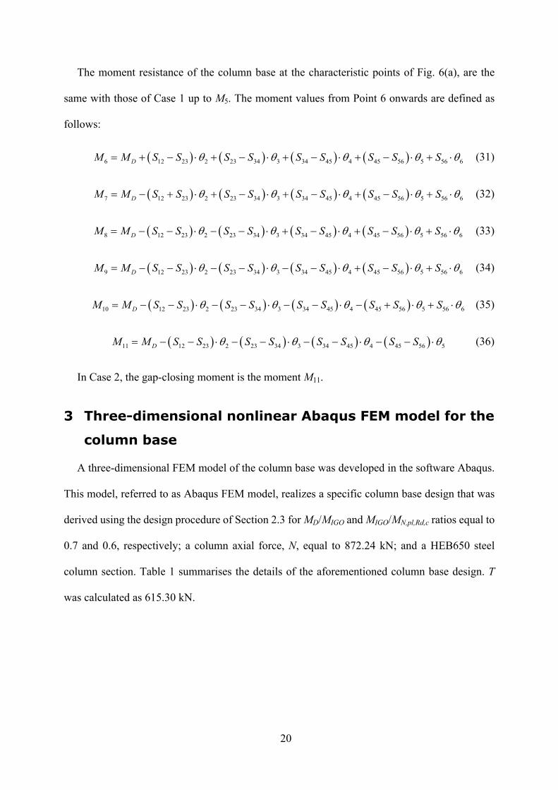
3.1 Model for the WHPs
A large number of simulations were conducted to identify the optimum mesh refinement of a
single WHP. The final mesh of a single WHP, which is shown in Fig. 8, consists of three-
dimensional eight-node linear hexahedral solid elements with reduced integration (C3D8R),
22
available in Abaqus. These C3D8R elements had a maximum side length of 8 mm at the external
parts of the WHP and a minimum side length of 3 mm at its internal parts.
Fig. 8 Mesh of a WHP
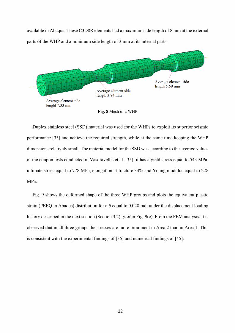
Duplex stainless steel (SSD) material was used for the WHPs to exploit its superior seismic
performance [35] and achieve the required strength, while at the same time keeping the WHP
dimensions relatively small. The material model for the SSD was according to the average values
of the coupon tests conducted in Vasdravellis et al. [35]; it has a yield stress equal to 543 MPa,
ultimate stress equal to 778 MPa, elongation at fracture 34% and Young modulus equal to 228
MPa.
Fig. 9 shows the deformed shape of the three WHP groups and plots the equivalent plastic
strain (PEEQ in Abaqus) distribution for a θ equal to 0.028 rad, under the displacement loading
history described in the next section (Section 3.2); φ≈θ in Fig. 9(c). From the FEM analysis, it is
observed that in all three groups the stresses are more prominent in Area 2 than in Area 1. This
is consistent with the experimental findings of [35] and numerical findings of [45].
23
(a)
(b)
(c)
Fig. 9 PEEQ distribution in the WHPs: (a) WHP at the gap-opening side; (b) WHP at the rocking-toe side; and (c) central WHP. The index i in the forces and moments notation denotes one WHP
24
Moreover, despite that the central WHPs were farther from the COR compared to the WHPs at
the rocking-toe side and, thus, were expected to develop higher stresses due to their larger lever
arms, their out-of-plane loading resulted in smaller peak stresses. Lastly, it is seen that the
optimized hourglass shape of the WHPs avoids stress concentrations and results in uniform
distribution of plastic deformation in the internal parts, while the external parts remain elastic.
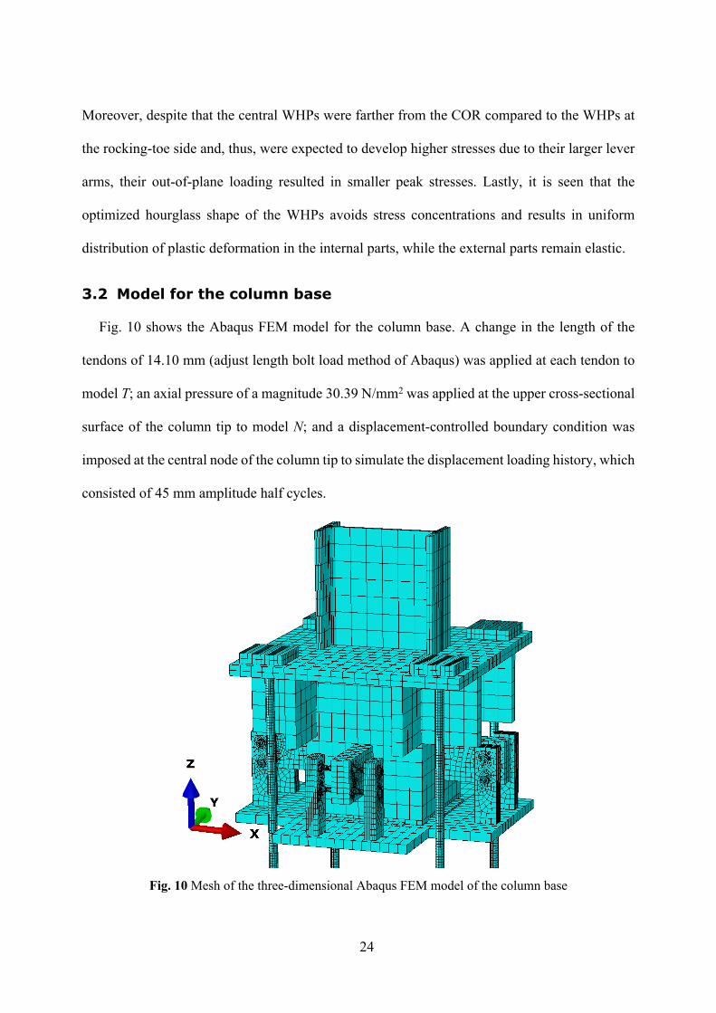
3.2 Model for the column base
Fig. 10 shows the Abaqus FEM model for the column base. A change in the length of the
tendons of 14.10 mm (adjust length bolt load method of Abaqus) was applied at each tendon to
model T; an axial pressure of a magnitude 30.39 N/mm2 was applied at the upper cross-sectional
surface of the column tip to model N; and a displacement-controlled boundary condition was
imposed at the central node of the column tip to simulate the displacement loading history, which
consisted of 45 mm amplitude half cycles.
Fig. 10 Mesh of the three-dimensional Abaqus FEM model of the column base
25
To model the welded interfaces, kinematic tie constraints were applied to the degrees of
freedom of the nodes between the supporting plates and the base plate; the anchor stand
stiffeners, the anchor stand and the CFT; the web plates and the CFT; the column and the anchor
stand; and the anchor stand and the CFT. Kinematic tie constraints were applied between the
shear bumpers and base plate, and, the tendon washer plates (Fig. 1) and tendons. Contact
interactions with normal ‘hard’ contact were specified between surface pairs that separate after
contact. These pairs are the tendons and anchor stand holes; the tendon washer plates and anchor
stand; and the shear bumpers and CFT. Between the foot end plate and base plate, and, the WHPs,
web plates and supporting plates, both normal hard contact and friction were applied with a
friction coefficient equal to 0.2 [7,45]. The mechanical-type full fixity boundary conditions were
applied at all degrees of freedom at the underside surface of the base plate and the bottom cross-
sectional surfaces of the tendons.
All the parts of the column base were modelled using C3D8R elements. In general, a finer
mesh was applied to regions with the likelihood of large plastic deformations and buckling, while
a coarser mesh to regions that were expected to be elastic.
The nominal stress-strain curves from coupon tests [35] were converted into true stress-plastic
strain curves. For the base plate, shear bumpers, foot end plate, CFT, anchor stand, anchor stand
stiffeners, tendon washer plates, web plates, supporting plates, and column, a S355 steel grade
with an elasto-plastic law and isotropic hardening rule was used. The material of the tendons had
nominal yield strength equal to 1050 MPa, modulus of elasticity 205 GPa, and elongation
capacity 7%.
3.3 Assessment of the Abaqus FEM model for the column base
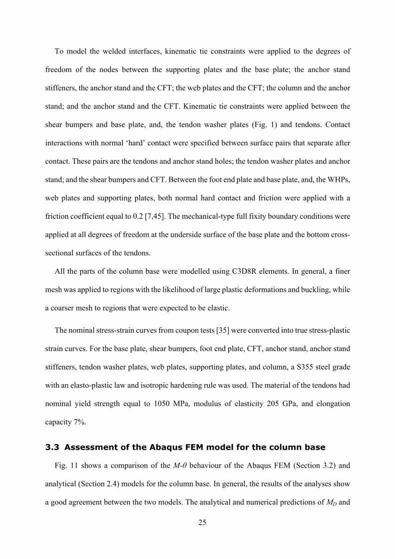
Fig. 11 shows a comparison of the Μ-θ behaviour of the Abaqus FEM (Section 3.2) and
analytical (Section 2.4) models for the column base. In general, the results of the analyses show
a good agreement between the two models. The analytical and numerical predictions of MD and
26
MIGO are almost the same. The elastic stiffness between the Abaqus FEM and analytical models
is also identical. A slight difference is observed in the post-elastic stiffness (i.e., after Point 4 in
Fig. 5(a)) of the two models because all the components of the Abaqus FEM model, except for
the tendons and WHPs (which have an elastoplastic force-displacement behaviour), were
modelled to have an elastic behaviour, as opposed to the analytical model where the
corresponding components were considered to behave rigidly.
Fig. 11 Comparison of the hysteretic behaviour of the column base from the Abaqus FEM and analytical model
The analysis results show that the Abaqus FEM model predicts self-centering behaviour.
Small differences are observed between the analytically and numerically predicted gap-closing
moments. The differences are due to the different energy dissipation between the two models.
The first reason for these differences is that the analytical model does not account for frictional
energy dissipation. The second reason is because the FEM behaviour of the central WHPs in the
column base differs from their analytical behaviour. This is due to the out-of-plane loading of
the central WHPs in the Abaqus FEM model (Fig. 9(c)), contrary to the in-plane loading assumed
for the development of the analytical model for the WHPs in [22]. The third reason is because
automatic stabilization schemes were used in FEM analysis to overcome numerical convergence
27
issues. These schemes introduce damping forces, which slightly increase the hysteretic energy
of the Abaqus FEM model.
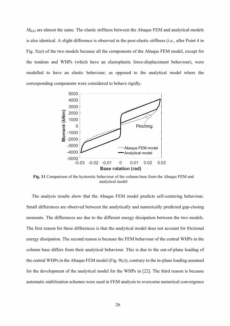
Apart from the plastic deformations in Areas 1 and 2 of the WHPs (Fig. 9), plastic
deformations are observed at the holes and bottoms of the supporting plates, as shown in Fig.
12.
(a)
(b)
Fig. 12 PEEQ concentration areas in the web plates and supporting plates of the column base for θ=0,028 rad: (a) at the gap-opening side; and (b) at the central WHPs
28
However, Vasdravellis et al. [45] showed that these concentrations of plastic deformation do not
affect the behaviour of the connection. Plastic deformations in the other parts of the column base
and local buckling phenomena in the column are not observed. Thus, the presumption of Section
2.1, i.e., that the column base can avoid the undesirable axial shortening and concurrent loss of
post-tensioning in its tendons, is confirmed. The Abaqus FEM model captures well the slight
pinching effect due to the hysteretic behaviour of the WHPs. Pinching is seen as a small flat
region in the unloading parts of the curves in Fig. 11 and is caused by the slight ovalization of
the supporting plate holes under the bearing forces of the external parts of the WHPs.
4 OpenSees FEM model for the column base
4.1 Model for the column base
A two-dimensional FEM model for the column base was developed in OpenSees [26] and
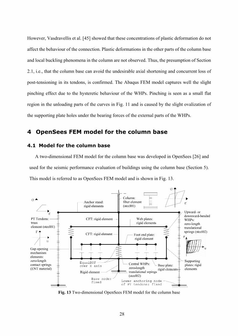
used for the seismic performance evaluation of buildings using the column base (Section 5).
This model is referred to as OpenSees FEM model and is shown in Fig. 13.
Fig. 13 Two-dimensional OpenSees FEM model for the column base
29
The column was modelled with nonlinear force-based fiber elements. The fibers are
associated with the Steel01 material of OpenSees for 355 MPa yield strength and 0.002 post-
yield stiffness ratio. Rigid elastic beam-column elements were used to model the rocking
interface, CFT and anchor stand. Rocking was simulated by using three zero-length translational
contact springs placed at equal distances along the left and right half-depth-part of the CFT cross-
section. These springs were associated with the ENT material in OpenSees, which exhibits an
elastic compression-no tension force-displacement behaviour. The compression stiffness of these
springs was set equal to twenty times the axial stiffness of the column, based on the approach of
[46]. Each WHP group was modelled with one zero-length hysteretic spring placed at the
geometric centre of the group. This spring follows a smooth Giuffre-Menegotto-Pinto hysteretic
rule with isotropic hardening. The tendons were modelled as truss elements. These elements had
a cross-sectional area equal to AER and material with bilinear elastoplastic hysteresis (Steel01).
To account for the initial post-tensioning, an initial strain equal to T/(AER∙EER) was imposed on
each truss element.
4.2 Assessment of the OpenSees FEM model for the column base
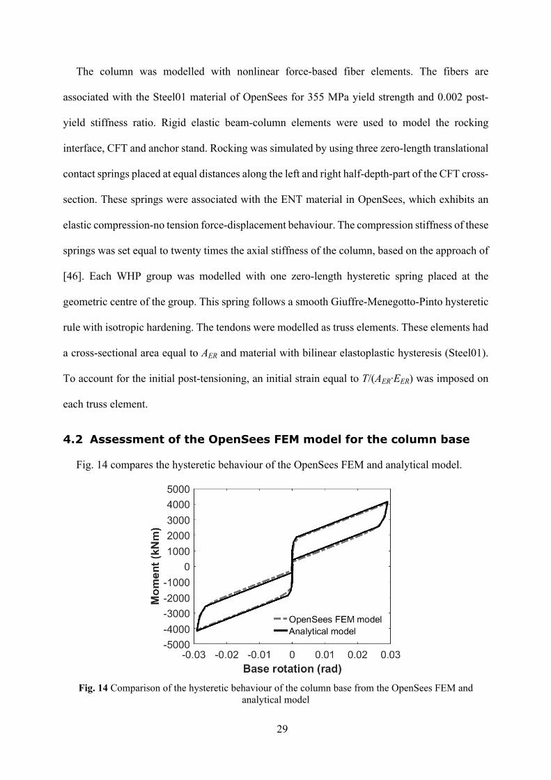
Fig. 14 compares the hysteretic behaviour of the OpenSees FEM and analytical model.
Fig. 14 Comparison of the hysteretic behaviour of the column base from the OpenSees FEM and analytical model
30
It is seen that the hysteretic responses of the two models are almost identical. The small
differences that are observed in two hysteretic responses are because the analytical model
considers as WHP lever arms the horizontal distances between the COR and the geometric centre
of each WHP group (Section 2.2).
5 Prototype building and design cases
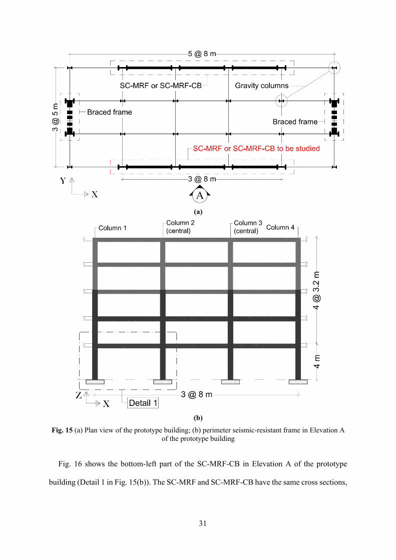
The prototype building in [44] was considered in this study. Fig. 15(a) shows the plan view
of the building, which has two identical perimeter seismic-resistant frames in the X direction.
The building has ductile non-structural elements, and therefore, the peak interstorey drift ratio
(θs,max) should be lower than 0.75% under the frequently occurred earthquake (FOE; 10%
probability of exceedance in 10 years). The design basis earthquake (DBE; 10% probability of
exceedance in 50 years) is expressed by the Type 1 elastic response spectrum of EC8 with peak
ground acceleration equal to 0.35g and ground type B. The maximum considered earthquake
(MCE) is assumed to have intensity 150% the intensity of the DBE. The study focuses on the X-
axis perimeter seismic-resistant frame that is placed on the bottom of the plan view of Fig. 15(a)
(Elevation A of the prototype building).
The frame of interest, the elevation of which is shown in Fig. 15(b), is designed as two
different seismic-resistant systems: first, as an SC-MRF with conventional full-strength column
bases, referred to as SC-MRF; and second, as an SC-MRF with the proposed column base,
referred to as SC-MRF-CB.
31
(a)
(b)
Fig. 15 (a) Plan view of the prototype building; (b) perimeter seismic-resistant frame in Elevation A of the prototype building
Fig. 16 shows the bottom-left part of the SC-MRF-CB in Elevation A of the prototype
building (Detail 1 in Fig. 15(b)). The SC-MRF and SC-MRF-CB have the same cross sections,
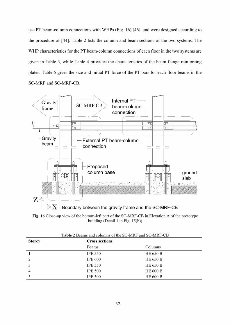
32
use PT beam-column connections with WHPs (Fig. 16) [46], and were designed according to
the procedure of [44]. Table 2 lists the column and beam sections of the two systems. The
WHP characteristics for the PT beam-column connections of each floor in the two systems are
given in Table 3, while Table 4 provides the characteristics of the beam flange reinforcing
plates. Table 5 gives the size and initial PT force of the PT bars for each floor beams in the
SC-MRF and SC-MRF-CB.
Fig. 16 Close-up view of the bottom-left part of the SC-MRF-CB in Elevation A of the prototype building (Detail 1 in Fig. 15(b))
Table 2 Beams and columns of the SC-MRF and SC-MRF-CB Cross sectionsStorey Beams Columns
1 IPE 550 HE 650 B 2 IPE 600 HE 650 B 3 IPE 550 HE 650 B 4 IPE 500 HE 600 B 5 IPE 500 HE 600 B
33
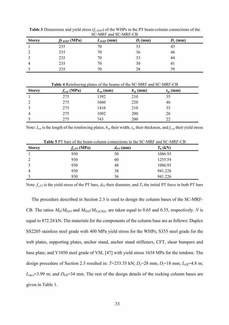
Table 3 Dimensions and yield stress (fy,WHP) of the WHPs in the PT beam-column connections of the SC-MRF and SC-MRF-CB
Storey fy,WHP (MPa) LWHP (mm) Di (mm) De (mm)1 235 70 33 432 235 70 36 463 235 70 33 444 235 70 30 415 235 70 28 39
Table 4 Reinforcing plates of the beams of the SC-MRF and SC-MRF-CB Storey fy,rp (MPa) Lrp (mm) brp (mm) trp (mm) 1 275 1392 210 35 2 275 1660 220 46 3 275 1416 210 35 4 275 1092 200 26 5 275 743 200 22
Note: Lrp is the length of the reinforcing plates, brp their width, trp their thickness, and fy,rp their yield stress
Table 5 PT bars of the beam-column connections in the SC-MRF and SC-MRF-CB Storey fy,PT (MPa) dPT (mm) T0 (kN) 1 930 50 1086.93 2 930 60 1255.54 3 930 48 1086.93 4 930 38 941.226 5 930 36 941.226
Note: fy,PT is the yield stress of the PT bars, dPT their diameter, and T0 the initial PT force in both PT bars
The procedure described in Section 2.3 is used to design the column bases of the SC-MRF-
CB. The ratios MD/MIGO and MIGO/MN,pl,Rd,c are taken equal to 0.65 and 0.35, respectively. N is
equal to 872.24 kN. The materials for the components of the column base are as follows: Duplex
SS2205 stainless steel grade with 400 MPa yield stress for the WHPs; S355 steel grade for the
web plates, supporting plates, anchor stand, anchor stand stiffeners, CFT, shear bumpers and
base plate; and Y1050 steel grade of VSL [47] with yield stress 1634 MPa for the tendons. The
design procedure of Section 2.3 resulted in: T=233.35 kN; De=28 mm; Di=18 mm; LER=4.8 m;
Lduct=3.99 m; and DER=34 mm. The rest of the design details of the rocking column bases are
given in Table 1.
34
6 Nonlinear models of the frames
To investigate the seismic performance of the SC-MRF and SC-MRF-CB, two-dimensional
frame models were developed in OpenSees. The models utilise the OpenSees model in [44] to
model the PT beam-column connections in both systems. This model was validated against
experimental results by Vasdravellis et al. [22] and found to accurately simulate the behaviour
of the specific PT connection typology. To reliably capture the beam local buckling, irrespective
of where the buckling occurs, this model uses the bilin material of OpenSees, which simulates
the modified Ibarra-Krawinkler deterioration model with bilinear hysteretic response, presented
in [48]. It is noted that determining whether the buckling occurs in the web or flanges of the
beams is out of the scope of this research. The OpenSees FEM model of Section 4.1 is used to
model the column bases of the SC-MRF-CB. To account for P-Δ effects, the gravity columns of
the tributary area of the SC-MRF and SC-MRF-CB were modelled as three lean-on columns,
i.e., one for each of the three bays of the two systems (Fig. 15(b)). These columns are pinned at
their base and continuous along their height. The flexural and axial stiffness of each lean-on
column are equal to the sum of the flexural and axial stiffness of the gravity columns that it
represents.
7 Monotonic and cyclic base shear vs roof drift behaviour
Fig. 17 shows the base shear coefficient (V/W; V: base shear; W seismic weight of the frame)-
roof drift (θr) behaviour of the SC-MRF-CB and SC-MRF from nonlinear monotonic static
(pushover) analysis under an inverted triangular force distribution. The graphs also indicate the
structural limit states and θr estimations under the FOE, DBE and MCE.
Fig. 17(a) shows the pushover curve of the SC-MRF. A column plastic hinge occurs at
θr=1.84%, i.e., above the DBE roof drift limit (1.61%). The first beam plastic hinge occurs at
θr=2.00%. The first beam local buckling occurs at θr=3.51%. After this point, the strength of the
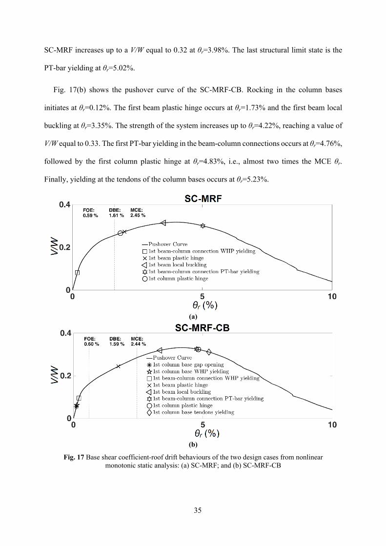
35
SC-MRF increases up to a V/W equal to 0.32 at θr=3.98%. The last structural limit state is the
PT-bar yielding at θr=5.02%.
Fig. 17(b) shows the pushover curve of the SC-MRF-CB. Rocking in the column bases
initiates at θr=0.12%. The first beam plastic hinge occurs at θr=1.73% and the first beam local
buckling at θr=3.35%. The strength of the system increases up to θr=4.22%, reaching a value of
V/W equal to 0.33. The first PT-bar yielding in the beam-column connections occurs at θr=4.76%,
followed by the first column plastic hinge at θr=4.83%, i.e., almost two times the MCE θr.
Finally, yielding at the tendons of the column bases occurs at θr=5.23%.
(a)
(b)
Fig. 17 Base shear coefficient-roof drift behaviours of the two design cases from nonlinear monotonic static analysis: (a) SC-MRF; and (b) SC-MRF-CB
36
The previous discussion shows that the SC-MRF-CB reaches the critical column plastic hinge
limit state at a significantly higher (approximately 2.5 times larger) θr compared to that of the
SC-MRF. Regarding the beam plastic hinge and beam local buckling limit states, the SC-MRF-
CB exhibits a comparable performance with the SC-MRF. Moreover, the SC-MRF-CB and SC-
MRF have comparable strengths.
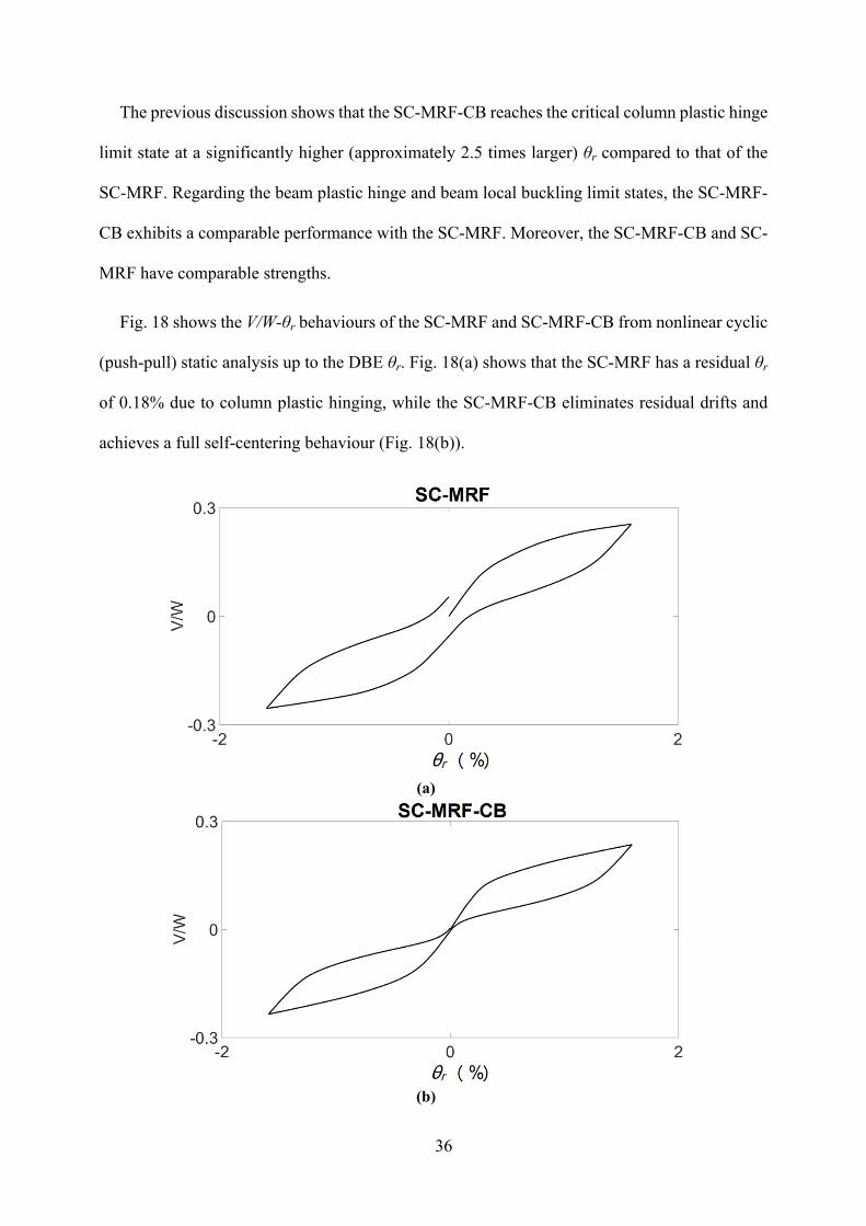
Fig. 18 shows the V/W-θr behaviours of the SC-MRF and SC-MRF-CB from nonlinear cyclic
(push-pull) static analysis up to the DBE θr. Fig. 18(a) shows that the SC-MRF has a residual θr
of 0.18% due to column plastic hinging, while the SC-MRF-CB eliminates residual drifts and
achieves a full self-centering behaviour (Fig. 18(b)).
(a)
(b)
37
Fig. 18 Base shear coefficient-roof drift behaviours of the two design cases from nonlinear cyclic static analysis: (a) SC-MRF; and (b) SC-MRF-CB
8 Nonlinear dynamic analyses
8.1 Ground motions and procedure for dynamic analyses
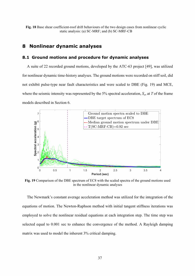
A suite of 22 recorded ground motions, developed by the ATC-63 project [49], was utilized
for nonlinear dynamic time-history analyses. The ground motions were recorded on stiff soil, did
not exhibit pulse-type near fault characteristics and were scaled to DBE (Fig. 19) and MCE,
where the seismic intensity was represented by the 5% spectral acceleration, Sa, at T of the frame
models described in Section 6.
Fig. 19 Comparison of the DBE spectrum of EC8 with the scaled spectra of the ground motions used in the nonlinear dynamic analyses
The Newmark’s constant average acceleration method was utilized for the integration of the
equations of motion. The Newton-Raphson method with initial tangent stiffness iterations was
employed to solve the nonlinear residual equations at each integration step. The time step was
selected equal to 0.001 sec to enhance the convergence of the method. A Rayleigh damping
matrix was used to model the inherent 3% critical damping.
38
8.2 Seismic assessment
The results of the 22 nonlinear response-history analyses for the two design cases were post-
processed and the median θs,max and residual interstorey drift ratios (θs,res) are shown in Table 6.
Table 6 Median θs,max and θs,res for the SC-MRF and SC-MRF-CB from nonlinear dynamic analyses Seismic-resistant system
System weight
Fundamental period
Damping ratio
θs,max*
(%)θs,res
*
(%)
W (kN) T1 (sec) ξ (%) DBE MCE DBE MCE
SC-MRF 10790,71 0.97 3 1.5816 2.2855 0.0405 0.1141
SC-MRF-CB 10790,71 0.92 3 1.1659 1.9035 0.0003 0.0011
* All the values are rounded off to four decimal digits
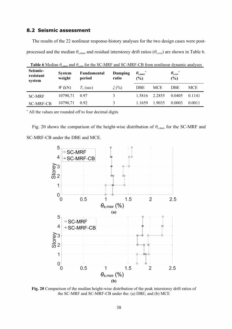
Fig. 20 shows the comparison of the height-wise distribution of θs,max for the SC-MRF and
SC-MRF-CB under the DBE and MCE.
(a)
(b)
Fig. 20 Comparison of the median height-wise distribution of the peak interstorey drift ratios of the SC-MRF and SC-MRF-CB under the: (a) DBE; and (b) MCE
39
The SC-MRF-CB has θs,max 26% and 17% lower than that of the SC-MRF under the DBE and
MCE, respectively. This is due to the CFT of the proposed column base, which decreases the
flexible length of the first-storey columns, and thus, reduces the period of the SC-MRF-CB
(Table 6).
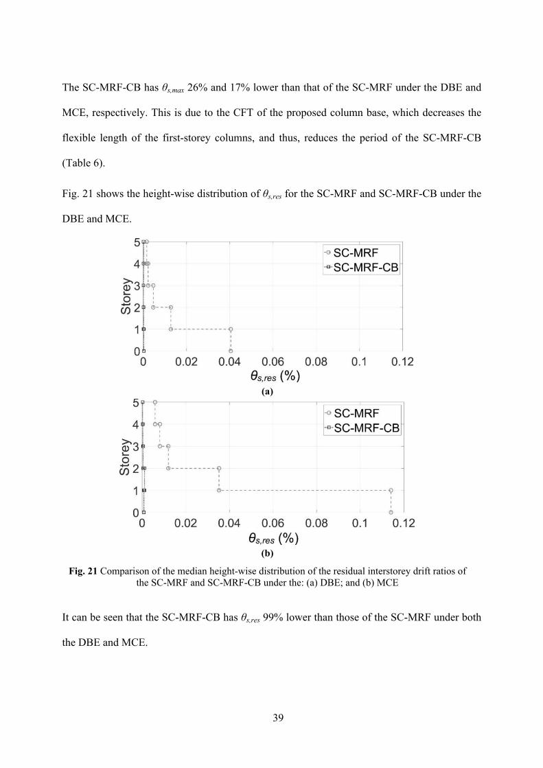
Fig. 21 shows the height-wise distribution of θs,res for the SC-MRF and SC-MRF-CB under the
DBE and MCE.
(a)
(b)
Fig. 21 Comparison of the median height-wise distribution of the residual interstorey drift ratios of the SC-MRF and SC-MRF-CB under the: (a) DBE; and (b) MCE
It can be seen that the SC-MRF-CB has θs,res 99% lower than those of the SC-MRF under both
the DBE and MCE.
40
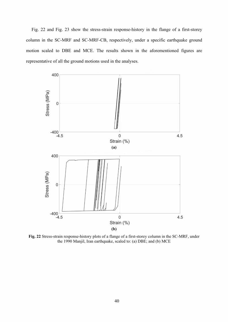
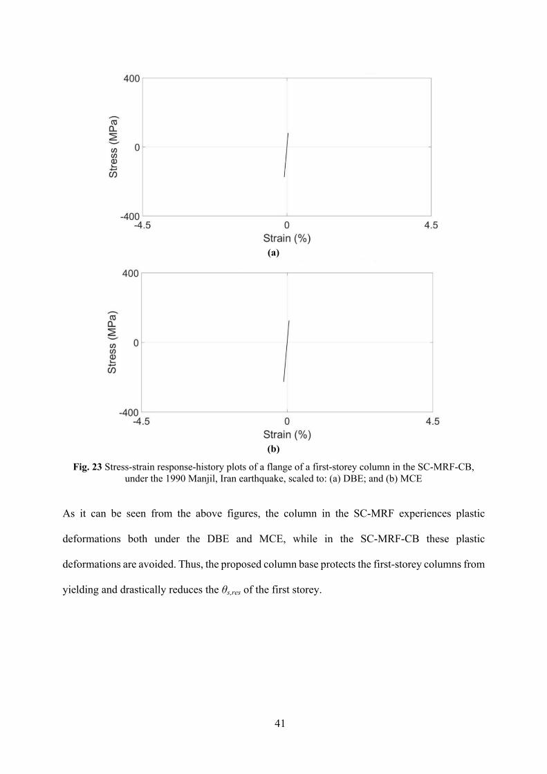
Fig. 22 and Fig. 23 show the stress-strain response-history in the flange of a first-storey
column in the SC-MRF and SC-MRF-CB, respectively, under a specific earthquake ground
motion scaled to DBE and MCE. The results shown in the aforementioned figures are
representative of all the ground motions used in the analyses.
(a)
(b)
Fig. 22 Stress-strain response-history plots of a flange of a first-storey column in the SC-MRF, under the 1990 Manjil, Iran earthquake, scaled to: (a) DBE; and (b) MCE
41
(a)
(b)
Fig. 23 Stress-strain response-history plots of a flange of a first-storey column in the SC-MRF-CB, under the 1990 Manjil, Iran earthquake, scaled to: (a) DBE; and (b) MCE
As it can be seen from the above figures, the column in the SC-MRF experiences plastic
deformations both under the DBE and MCE, while in the SC-MRF-CB these plastic
deformations are avoided. Thus, the proposed column base protects the first-storey columns from
yielding and drastically reduces the θs,res of the first storey.
42
9 Summary and conclusions
This paper proposes a self-centering steel column base with high-strength steel post-tensioned
(PT) tendons and hourglass shape steel yielding devices (WHPs). The following conclusions are
drawn:
Damage is concentrated within the replaceable WHPs, while the rest of the column
base is expected to remain damage-free. The column base allows for multiple
arrangements of the PT tendons outside the perimeter of the column section. This
feature, coupled with selecting appropriate characteristics for the tendons and WHPs
allows for the independent tuning of the moment resistance, rotational stiffness, and
self-centering capability of the column base. Furthermore, the proposed column base
exhibits increased rotation capacity compared to its conventional counterpart, and
avoids column axial shortening and loss of post-tensioning.
An analytical model and an associated design procedure are presented to predict the
hysteretic behaviour and all structural limit states of the proposed column base.
The behaviour of the column base has been assessed with detailed three-dimensional
nonlinear finite element method (FEM) models in the software Abaqus, while its
effect on the seismic response of a steel building has been quantified by nonlinear
dynamic analysis in the software OpenSees. The FEM models predict and simulate
well the hysteretic behaviour of the column base. The results of the FEM models are
in good agreement with the analytical model and show that the column base can avoid
non-repairable damage even under very large rotations. Under such rotations, small
inelastic deformations may be developed at the holes and bottoms of the supporting
plates without affecting the behaviour of the column base.
43
The results of nonlinear dynamic analyses show that the column base protects the first-
storey columns from yielding and drastically reduces the first-storey residual drifts
under the design and maximum considered earthquake intensities.
Acknowledgments
Financial support for this work was provided by the Engineering and Physical Science
Research Council of the United Kingdom (EPSRC); Award Ref.: 1500450.
References
[1] A. Aviram, B. Stojadinovic, A. Der Kiureghian, Performance and reliability of exposed
column base plate connections for steel moment-resisting frames, Berkeley, CA, USA,
2010.
[2] J. Ruiz-García, A. Kanvinde, Effect of column base flexibility on residual drift demands
of low-rise steel moment-resisting frames, in: 2013 World Congr. Adv. Struct. Eng. Eng.
Mech. (ASEM13), Sept. 8-12, Jeju, Korea, 2013: pp. 627–639.
[3] F. Zareian, A. Kanvinde, Effect of column-base flexibility on the seismic response and
safety of steel moment-resisting frames, Earthq. Spectra. 29 (2013) 1537–1559.
doi:10.1193/030512EQS062M.
[4] C.-C. Chou, J.-H. Chen, Analytical model validation and influence of column bases for
seismic responses of steel post-tensioned self-centering MRF systems, Eng. Struct. 33
(2011) 2628–2643. doi:10.1016/j.engstruct.2011.05.011.
[5] M. Eröz, D.W. White, R. DesRoches, Direct analysis and design of steel frames
accounting for partially restrained column base conditions, J. Struct. Eng. 134 (2010)
1508–1517. doi:10.1061/(ASCE)0733-9445(2008)134:9(1508).
[6] BS EN 1998-1, Eurocode 8: Design of structures for earthquake resistance - Part 1:
44
General rules, seismic actions and rules for buildings., 2013.
[7] BS EN 1993-1-8, Eurocode 3 : Design of steel structures — Part 1-8 : Design of joints,
United Kingdom, 2010.
[8] R.W. Clough, A.A. Huckelbridge, Preliminary Experimental Study of Seismic Uplift of a
Steel Frame, 1977.
[9] M. Long, C. Bergad, Analysis of Rotational Column with Plastic Hinge, in: 2004 Annu.
Tri-Center Earthq. Eng. Symp. Young Res., MCEER, Kiawah Island Golf Resort,
Charleston, South Carolina, 2004: pp. 183–195.
https://mceer.buffalo.edu/education/reu/04Proceedings/12Long_Bergad.pdf.
[10] T. Takamatsu, H. Tamai, Non-slip-type restoring force characteristics of an exposed-type
column base, J. Constr. Steel Res. 61 (2005) 942–961. doi:10.1016/j.jcsr.2005.01.003.
[11] T. Takamatsu, H. Tamai, T. Yamanishi, Self-centering performance of non-slip-type
exposed column base, in: A.W. Federico Mazzolani (Ed.), 5th Int. Conf. Behav. Struct.
Seism. Areas, STESSA 2006, August 14-17, CRC Press, Taylor & Francis Group,
Yokohama, Japan, 2006: pp. 357–362.
[12] M. Midorikawa, T. Azuhata, T. Ishihara, A. Wada, Shaking table tests on seismic response
of steel braced frames with column uplift, Earthq. Eng. Struct. Dyn. 35 (2006) 1767–1785.
doi:10.1002/eqe.603.
[13] T. Yamanishi, K. Kasai, T. Takamatsu, H. Tamai, Innovative Column-Base Details
Capable of Tuning Rigidity and Strength for Low to Medium-Rise Steel Structures, in:
15th World Conf. Earthq. Eng., Lisbon, Portugal, 2012.
[14] H. Chi, J. Liu, Seismic behavior of post-tensioned column base for steel self-centering
moment resisting frame, J. Constr. Steel Res. 78 (2012) 117–130.
doi:10.1016/j.jcsr.2012.07.005.
45
[15] J.D. Tait, G.K. Sidwell, J.F. Finnegan, Case study - Elevated apartments - A rocking 15
storey apartment building, in: Steel Innov. Conf. 2013 Christchurch, New Zeal. 21-22
Febr., 2013.
[16] J. Borzouie, G.A. Macrae, J.G. Chase, G.W. Rodgers, G.C. Clifton, Experimental studies
on cyclic performance of column base weak axis aligned asymmetric friction connection,
J. Constr. Steel Res. 112 (2015) 252–262. doi:10.1016/j.jcsr.2015.05.007.
[17] M. Ikenaga, M. Nakashima, T. Nagae, Reduction of residual story drift of moment
resisting frame using self-centering column bases, in: Federico M. Mazzolani;James M.
Ricles;Richard Sause (Ed.), Stessa 2009 - Behav. Steel Struct. Seism. Areas, Taylor &
Francis Group, London, UK, Philadelphia, Pennsylvania, USA, 2009: pp. 465–471.
[18] C.-C. Chen, H.-W. Lin, R.-S. Tsai, Self-centering and energy dissipation of a post-
tensioned steel column base, in: Second Eur. Conf. Earthq. Eng. Seismol. (2ECCES), 25-
29 August, Istanbul, Turkey, 2014.
[19] H. Chi, J. Liu, Response of self-centering steel moment resisting frames with post-
tensioned column bases under seismic loading, in: 4th Int. Conf. Earthq. Eng. Oct. 12-13,
Taipei, Taiwan, 2006.
[20] M. Ikenaga, T. Nagae, M. Nakashima, K. Suita, Development of column bases having
self-centering and damping capability, STESSA 2006. (2006) 703–708.
[21] G.A. MacRae, C.R. Urmson, W.R. Walpole, P. Moss, K. Hyde, C. Clifton, Axial
shortening of steel columns in buildings subjected to earthquakes, Bull. New Zeal. Soc.
Earthq. Eng. 42 (2009) 275–287.
[22] G. Vasdravellis, T.L. Karavasilis, B. Uy, Large-Scale Experimental Validation of Steel
Post-Tensioned Connections with Web Hourglass Pins, J. Struct. Eng. 139 (2013) 1033–
42. doi:10.1061/(ASCE)ST.1943-541X.0000696.
46
[23] V.C. Kamperidis, T.L. Karavasilis, G. Vasdravellis, Design and modeling of a novel
damage-free steel column base, in: Eighth Int. Conf. Adv. Steel Struct. (ICASS 2015),
Lisbon, Portugal, July 22-24, 2015: p. Paper No. 118. http://wrap.warwick.ac.uk/78241/.
[24] F. Freddi, C.A. Dimopoulos, T.L. Karavasilis, Rocking damage-free steel column base
with friction devices: design procedure and numerical evaluation, Earhtquake Eng. Struct.
Dyn. (2017). doi:10.1002/eqe.2904.
[25] Dassault Systèmes Simulia Corporation, Abaqus, (2013). http://www.3ds.com/products-
services/simulia/products/abaqus/.
[26] U. of C. Pacific Earthquake Engineering Research Center (PEER), OpenSees, (2015).
http://opensees.berkeley.edu.
[27] J.T. Hewes, M.J.N. Priestley, Seismic design and performance of precast concrete
segmental bridge columns. Report No. SSRP-2001/25, La Jolla, California 92093-0085,
USA, 2002.
[28] T. Guo, Z. Cao, Z. Xu, S. Lu, Cyclic load tests on self-centering concrete pier with
external dissipators and enhanced durability, J. Struct. Eng. 142 (2016) 4015088.
doi:10.1061/(ASCE)ST.1943-541X.0001357.
[29] C.-C. Chou, J.-H. Chen, Column restraint in post-tensioned self-centering moment
frames, Earthq. Eng. Struct. Dyn. 39 (2010) 751–774. doi:10.1002/eqe.972.
[30] C.-C. Chou, Y.-C. Chen, Cyclic tests of post-tensioned precast CFT segmental
bridgecolumns with unbonded strands, Earthq. Eng. Struct. Dyn. 35 (2006) 159–175.
doi:10.1002/eqe.512.
[31] G. Guerrini, J.I. Restrepo, M. Massari, A. Vervelidis, Seismic Behavior of Posttensioned
Self-Centering Precast Concrete Dual-Shell Steel Columns, J. Struct. Eng. 141 (2015)
4014115. doi:10.1061/(ASCE)ST.1943-541X.0001054.
47
[32] M.M. Garlock, J.M. Ricles, R. Sause, Experimental Studies of Full-Scale Posttensioned
Steel Connections, J. Struct. Eng. 131 (2005) 438–448. doi:10.1061/(ASCE)0733-
9445(2005)131:3(438).
[33] J.D. Newell, C.-M. Uang, Cyclic Behavior of Steel Wide-Flange Columns Subjected to
Large Drift, J. Struct. Eng. 134 (2008) 1334–1342. doi:10.1061/(ASCE)0733-
9445(2008)134:8(1334).
[34] J.B. Mander, C.-T. Cheng, Seismic resistance of bridge piers based on damage avoidance
design. Technical Report NCEER-97-0014, Buffalo, NY, USA, 1997.
[35] G. Vasdravellis, T.L. Karavasilis, B. Uy, Design rules, experimental evaluation, and
fracture models for high-strength and stainless-steel hourglass shape energy dissipation
devices, J. Struct. Eng. 140 (2014) 4014087. doi:10.1061/(ASCE)ST.1943-
541X.0001014.
[36] C.B. Barthes, Design of Earthquake Resistant Bridges Using Rocking Columns,
University of California, Berkeley, 2012. http://escholarship.org/uc/item/7gf04022.
[37] BS EN 1993-1-1, Eurocode 3: Design of steel structures - Part 1-1: General rules and rules
for steel buildings, United Kingdom, 2009.
[38] BS EN 1993-1-5, Eurocode 3: Design of steel structures – Part 1-5: Plated structural
elements, 2006.
[39] SCI/BCSA Connections Group, Joints in Steel Construction: Moment connections
(P207), Imperial College London, Silwood Park Campus, Buckhurst Rd, Ascot SL5 7QN,
United Kingdom, 1997.
[40] SCI/BCSA Connections Group, Joints in steel construction: Moment-resisting joints to
Eurocode 3 (P398), Imperial College London, Silwood Park Campus, Buckhurst Rd,
Ascot SL5 7QN, United Kingdom, 2013.
48
[41] H. Chi, J. Liu, M. Garlock, Design and Analytical Validation of Post-Tensioned Column
Bases, in: Struct. Congr. 2008 Crossing Borders, April 24-26, American Society of Civil
Engineers, Reston, Vancouver, British Columbia, Canada, 2008: pp. 1–6.
doi:10.1061/41016(314)254.
[42] M.E.M. Garlock, R. Sause, J.M. Ricles, Behavior and Design of Posttensioned Steel
Frame Systems, J. Struct. Eng. 133 (2007) 389–99. doi:10.1061/(ASCE)0733-
9445(2007)133:3(389).
[43] H.-J. Kim, C. Christopoulos, Friction Damped Posttensioned Self-Centering Steel
Moment-Resisting Frames, J. Struct. Eng. 134 (2008) 1768–1779.
doi:10.1061/(ASCE)0733-9445(2008)134:11(1768).
[44] A.S. Tzimas, A.I. Dimopoulos, T.L. Karavasilis, EC8-based seismic design and
assessment of self-centering steel frames with viscous dampers, J. Constr. Steel Res. 105
(2015) 60–73.
[45] G. Vasdravellis, T.L. Karavasilis, B. Uy, Finite element models and cyclic behavior of
self-centering steel post-tensioned connections with web hourglass pins, Eng. Struct. 52
(2013) 1–16. doi:http://dx.doi.org/10.1016/j.engstruct.2013.02.005.
[46] A.I. Dimopoulos, T.L. Karavasilis, G. Vasdravellis, B. Uy, Seismic design, modelling and
assessment of self-centering steel frames using post-tensioned connections with web
hourglass shape pins, Bull. Earthq. Eng. 11 (2013) 1797–1816. doi:10.1007/s10518-013-
9437-4.
[47] VSL International Ltd, Post-tensioning, stay cables & construction methods, Prod. Broch.
VSL STRAND POST-TENSIONING Syst. (2013). www.vsl.com.
[48] D.G. Lignos, H. Krawinkler, Deterioration Modeling of Steel Components in Support of
Collapse Prediction of Steel Moment Frames under Earthquake Loading, J. Struct. Eng.

49
137 (2011) 1291–1302. doi:10.1061/(ASCE)ST.1943-541X.0000376.
[49] FEMA, Quantification of building seismic performance factors (ATC-63 Project), USA,
2009.