Embed Size (px)
Citation preview

21st Australasian Fluid Mechanics ConferenceAdelaide, Australia10-13 December 2018
Selective optical manipulation of particles in acoustic levitation
G. Dumy1,2, M. Hoyos1 and J. L. Aider1
1Laboratoire PMMH, UMR7636 CNRS,ESPCI Paris, 10 rue Vauquelin, Paris, France
2Paris Descartes, Sorbonne Paris Cite, Paris, France
Abstract
Acoustic Radiation Force (ARF) is commonly used to createstable large-scale aggregates of particles in levitation (so-called”acoustic levitation) in a micro cavity. We show in the fol-lowing work that this well-known and well-controlled aggre-gation process can be reversed without contact or external flowif the aggregated particles are enlightened with the proper op-tical wavelength. This coupled optics and acoustics effect hasbeen observed with various kinds of particles and different opticwavelengths, showing high reproducibility. The phenomenonis studied using fluorescent micro-metric polystyrene particleswithout flow, and the effects of acoustic energy and illuminationpower have been quantitatively assessed. Since it is a tag freephenomenon, does not need high energies to happen and that itworks with biological objects such as algae, red blood cells andbacteria, it may pave the way to a broad range of applications.
Introduction
Acoustic manipulation of micro-objects (particles, cells, bacte-ria, micro-bubbles, etc.) can be realized using ultrasonic stand-ing waves in a fluidic or microfluidic resonator [1, 2]. Acous-tic focusing of suspensions (or ”acoustophoresis”) is a complexphenomenon which has been the subject of many theoreticalstudies. It occurs in a micro-channel or a micro-cavity when theultrasonic frequency fac, emitted into the cavity through a trans-mitter layer and reflected by the opposite wall (reflection layer),matches the resonance condition λac = 2h, h being the height ofthe device (Fig. 1). In this case, particles such as plastic beads orliving cells are drawn toward the acoustic pressure node createdat mid-height of the cavity by the so-called Acoustic RadiationForce (ARF).
There are different theoretical models describing the ARF,based on more or less simplifying hypothesis [3, 4, 5]. King[3] was the first to propose computations on the forces on par-ticles in a sound field based on several simplifying hypothesis.In particular, he considered the particles as rigid spheres. Inthe following, we will use the Yosioka model [4] which takesinto account the compressibility of the spherical particles in themodeling. In this case, the primary Acoustic Radiation Force(ARF) Fac responsible of particle acoustic levitation can be de-fined as:
−→Fac =π
4〈Eac〉 k d3
p FY sin(2 kac z) −→e z (1)
where 〈−〉 denotes time averaging, dp is the particle diameter,〈Eac〉 is the time-averaged acoustic energy density inside thechannel, k = 2π
λac= 2π fac
c is the wave number of the acousticplane wave of frequency fac, FY is the contrast factor, a positive(for polystyrene particles in water) numerical constant, and z isthe axial (or vertical) position of the particle, z = 0 being at thebottom of the channel and z = h being at the top of the channel(Fig. 1). The z axis also corresponds to the wave propagationdirection.
Figure 1: Principle of acoustic focusing of a suspension of par-ticles in an micrometric acoustic resonator (a, b) and of the cre-ation of an aggregate in acoustic levitation (c). Red lines denotethe standing ultrasonic wave pressure profile. (d) The aggregateof fluorescent particles can then be broken up when, illuminatedwith a specific wavelength.
The acoustic contrast factor of a given particle of density ρp ina medium of density ρ f is defined as:
FY =1+ 2
3
(1− ρ f
ρp
)2+ ρ f
ρp
−ρ f c2
f
3 ρp c2p
(2)
where cp is the speed of sound in the particles material andcf is the speed of sound in the fluid. In this investigation weare dealing with an ultrasonic standing wave with a frequencyfac ∼ 2 MHz. The amplitude of the corresponding acousticforce typically ranges from 10−12 to 10−14 N (for instance, withpolystyrene particles of 1 µm dispersed in our resonator filledwith water, this force equals 2.8 10−13 N).
Ultrasonic radiation forces are capable of levitating and aggre-gating in a fast and smooth manner a large number of particlesor living cells in suspension in a cavity or channel. Once the par-ticles have reached the nodal plane, the axial component of theforce becomes null and the transverse component is no longernegligible. Indeed it has been shown that this component isabout one hundred times weaker than the axial component andis then negligible during the focusing step [6]. Whitworth [7]derived the transverse component of the ARF for a radially sym-metric acoustic wave in the nodal plane:
FT = d3p
3(ρp−ρ f )
ρ f +2ρp∇〈Eac〉 (3)
This transverse component depends directly on the radial gra-dient of the acoustic energy ∇〈Eac〉 and is responsible for theaggregation of particles in the levitation plane toward the localmaximum of acoustic energy.
Creation of large-scale aggregates under acoustic radiationforce
As explained in the previous section, the acoustic radiationforce is a simple and fast process to create large aggregates ofparticles in acoustic levitation. Once the ultrasonic wave is gen-erated with the proper frequency into the cavity, the ARF forcesthe suspended particles to move toward the nodal plane, at mid-height of the cavity. Once the particles have reached the focus-ing plane, the transverse component of the ARF forces the par-ticles to move toward the location of the maximum of acousticenergy. When the particles are close enough then the Bjerknesforce keep the particles close together, making the aggregatemore compact and stable. The creation of a large aggregateof particles is illustrated on Fig. 2 a) with 1.62 µm polystyrenebeads. The focusing time Tf oc can be very short (a few tenths ofsecond), depending on the amplitude of the acoustic field. Oncethe aggregate is formed, it can be kept in acoustic levitation aslong as needed and will remain stable, with the same spatial or-ganization [8]. The aggregation process is efficient on particlesas well as cells or active matter (bacteria). It can be used as atool for creating an acoustic trap, especially for self-propelledorganisms like bacteria that can be held in levitation in acousticconfinement [9].
Figure 2: a) The three first pictures show the formation of alarge stable aggregate of 1.62 µm particles. It can be kept stableas long as needed. b) When the same aggregate is illuminatedwith a green light (λlight = 545 nm) at a much higher intensity,the particles are quickly ejected from the illuminated region. c)We observe the same phenomenon with 1.75 µm particles fluo-rescing in green and illuminated with a blue (λlight = 488 nm)light at the same intensity. Time steps between frames is200 ms.
Breakup of aggregates
As mentioned previously, once an aggregate of passive particlesis formed using ARF, it remains stable and can be kept in lev-itation as long as needed. Without the use of an external flowor force, there is no way to break it up, apart from loweringenough (or turning off) the acoustics. In that case the aggregateeither disintegrates in small aggregates and particles which allsettle down, or the entire aggregate settles down, with particlesstill being stuck to each other by lubrication forces. That will bethe case if the particles had time to interact strongly with eachother.
There can be other behaviors with active matter, for instancewhen aggregating bacteria (active) or Janus particles (pseudoactive). Indeed, when aggregated bacteria kept in levitation are
released from the confinement imposed by the acoustic field,the aggregate inner active pressure triggers an explosion-likebreakup, radially ejecting bacteria confined in the acoustic field[9]. In the case of Janus particles, as demonstrated by Takatoriet al. [10], the relaxation of an active crystal has been observedand described when the acoustic confinement is released.
What we shall report in the following is a new breakup processof aggregates of particles kept in acoustic levitation.
Breakup of aggregates of fluorescent particles by light
First observations
We first use fluorescent polystyrene particles of diameter dp =1.62 µm which can be excited with green light and fluoresce inred light (λabs = 545 nm and λem = 620 nm). Large aggregatesof particles are created in acoustic levitation in the cylindricalresonator described on supplementary material figure at [URLwill be inserted by AIP for SuppPub1.jpg] using fac = 1.86MHz resonant frequency. As mentioned previously, the aggre-gates can be kept stable as long as needed when observed witha white light and at low power of illumination (The regular ag-gregation process can be seen in Fig. 2 a) ).
Interestingly, when using a monochromatic (λ= 545nm) illumi-nation, and gradually increasing the light intensity, the aggrega-tion process is stopped. For even higher intensities, the aggre-gate starts to eject particles from its periphery. This ejectionprocess goes on until disruption of the entire aggregate. If thelight intensity is still increased, then this ejection process takesthe form of an explosion, as can be seen on Fig. 2 b). One as-tonishing effect is that the particles escape the aggregate whileremaining in the focal plane of the camera, i.e. in levitation.This result suggests that the primary radiation force (responsi-ble for the acoustic focusing) is not affected, but that transversaland Bjerknes forces seems to be completely counterbalanced orscreened by another force.
The disaggregation only occurs in acoustic levitation (no ef-fect observed on beads that are on the bottom or top of thecavity) and when the particles are illuminated with the properwavelength corresponding to the fluorescent particle absorptionwavelength. In this case, for instance, the aggregate remainsunchanged if illuminated with a blue light (λ = 488 nm).
Another interesting point is that the effect is reversible: oncethe light intensity is lowered under a given threshold, then thestandard acoustic aggregation process starts again with the samedynamics.
This phenomenon is highly reproducible and not limited to agiven type of fluorescent bead. It has been tested with variousfluorescent particles, all experiments leading to the same obser-vations. Another example is shown Fig. 2 c), where an aggre-gate made from a solution of particles of diameter dp = 1.75 µmwhich can be excited with blue light and fluoresce in green light(λabs = 450 nm and λem = 532 nm) is formed under an acousticfield of frequency fac = 1.85 MHz. As soon as we illuminatethis aggregate with a blue light (λ = 488 nm at 50 mW.mm−2),the aggregate starts to eject particles from its periphery, as wasobserved before. The same expulsion phenomenon could beobserved in a very reproducible way using these different fluo-rescences and with various diameters dp, ranging from 0.883 to5 µm, when the aggregate was illuminated with the right wave-length.
Influence of the light intensity
As mentioned in the previous section, one can find a critical il-lumination intensity Icrit for which the acoustic radiation force

and the photo-acoustic force seem to balance. To further in-vestigate the dependence of the effect on the amount of lightinjected in the aggregate, we did vary the light intensity for agiven aggregate of 1.62 µm beads, at a fixed amplitude of theacoustic field. In the following the amplitude of the acousticforce is considered proportional to the acoustic energy insidethe resonator (cf. Eq. 1). In this case, this energy is constant(〈Eac〉= 106 J.m−3).
We measure the ejection velocity ve j for each illumination. Theevolution of ve j as a function of the illumination power Plight isplotted on 3 a). A linear evolution is found suggesting a directproportionality of the ejection velocity with the injected illumi-nation power: ve j(Plight) ∝ Plight .
10 20 30 40 50
Light power in mW.mm -2
4
6
8
10
12
14
16
Eje
ctio
n sp
eed
in µ
m.s
-1
Ejection speed
0.3815 x - 1.1144 fit , R 2 = 0.9912
101
Piezoelectric voltage
101
Eje
ctio
n sp
eed
in µ
m.s
-1
Ejection speed
0.75 x3/2 - 0.02525 , R2 = 0.938
Figure 3: Evolution of the ejection velocity as a function of theillumination power (a) or of the amplitude of the ARF (b) for agiven suspension of rp = 1.6 µm polymer beads.
Influence of the amplitude of the ARF
Similarly the influence of the acoustic field amplitude was in-vestigated. We also found that the phenomenon was no longerobserved when the acoustic field is turned off. This time, wedid explore a range of ARF amplitudes ranging form 8 to 200J.m−3 for a given illumination power (50 mW.mm−2), all otherparameters being kept constant
Using the same spatio-temporal analysis, we plot on 3 b) onlogarithmic scale the evolution of ve j as a function of the acous-tic energy in J.m−3 for a given illumination power Plight . Inthis case, a linear evolution is found suggesting a scaling ofthe ejection velocity as a 3/4 power law of the acoustic energy:ve j(〈Eac〉)∝ 〈Eac〉3/4. Combining both results, and consideringthat both parameters are independent, one can define the fol-lowing scaling law for the ejection velocity: ve j(Plight ,〈Eac〉) ∝
Plight · 〈Eac〉3/4.
Separation of a binary mixture
To demonstrate the ability of the photoacoustic effect to sepa-rate a binary mixture, we used a mixed solution of two colloidalparticles: polystyrene particles of mean diameters dp1 = 1.62µm and dp2 = 0.883 µm, with absorption wavelengths λ1 =532 nm and λ2 = 450 nm) with an equal volume fraction of0.025 %. First we created a large aggregate in acoustic levita-tion, following the same process as in the previous experiments(1.903 MHz and 200 J.m−3) and using the same resonator. Af-ter a relatively short focusing time, the aggregate becomes sta-ble in acoustic levitation and it contains an homogeneous mix-ture of both particles.
The upper row of Fig. 4 shows the aggregates in acoustic lev-itation but using different filters. Fig. 4 a) corresponds to anobservation without filters. It shows a large aggregate in stableacoustic levitation. When using a green (Fig. 4 b) or red fil-ter (Fig. 4 c) one can see that both types of particles are rather
homogeneously distributed over the entire aggregate. To ourknowledge, it is impossible to separate such a mixture of parti-cles once they are so well mixed.
Figure 4: Separation of a binary mixture of 1.62 µm red fluores-cent particles, and 0.883 µm green fluorescent particles. a), b)and c) pictures show the stable aggregate created by the acous-tic force. The three pictures corresponds to observations with-out selective filter (a) and with respectively green (b) and red(c) filters. The pictures d), e) and f) show the aggregate afterapplying a strong illumination to the green fluorescent particlesduring 10 seconds and after all the ejected particles had time tofocus again toward the aggregate. One can see that the new ag-gregate is no longer an homogeneous mixture of the two typesof particles. It is now made of two clearly separate regions: onecontaining the red particles, the other one containing the greenparticles.
The aggregate has then been illuminated with a blue light(λlight = 488 nm) at a constant power of 30 mW.mm−2 during10 seconds, then the illumination has been turned off. The re-sulting aggregate could then be observed once the particles ag-gregated under the influence of ARF. The result is shown on thelower part of Fig. 4. Fig. 4 d) shows the aggregate after a fewseconds without any optical excitation. One can see that the ag-gregate has changed from its original shape. Fig. 4 e) and Fig. 4f) shows the pictures of the aggregate when observed respec-tively with a green and red filter. We can clearly see that theaggregate no longer contains an homogenous mixture of bothparticles. The red fluorescent beads are now on one side ofthe aggregate while the green are now on the other side of theaggregate. This is a clear demonstration that the two types ofparticles have indeed been separated by the photoacoustofluidiceffect. The separation was very fast (a few seconds) and effi-cient. The particles absorbing the illumination wavelength (thesmaller ones in this case) have indeed been extracted from theaggregate before being attracted again toward the aggregate oflarger particles, which did not breakup, because of the ARF.
Discussion
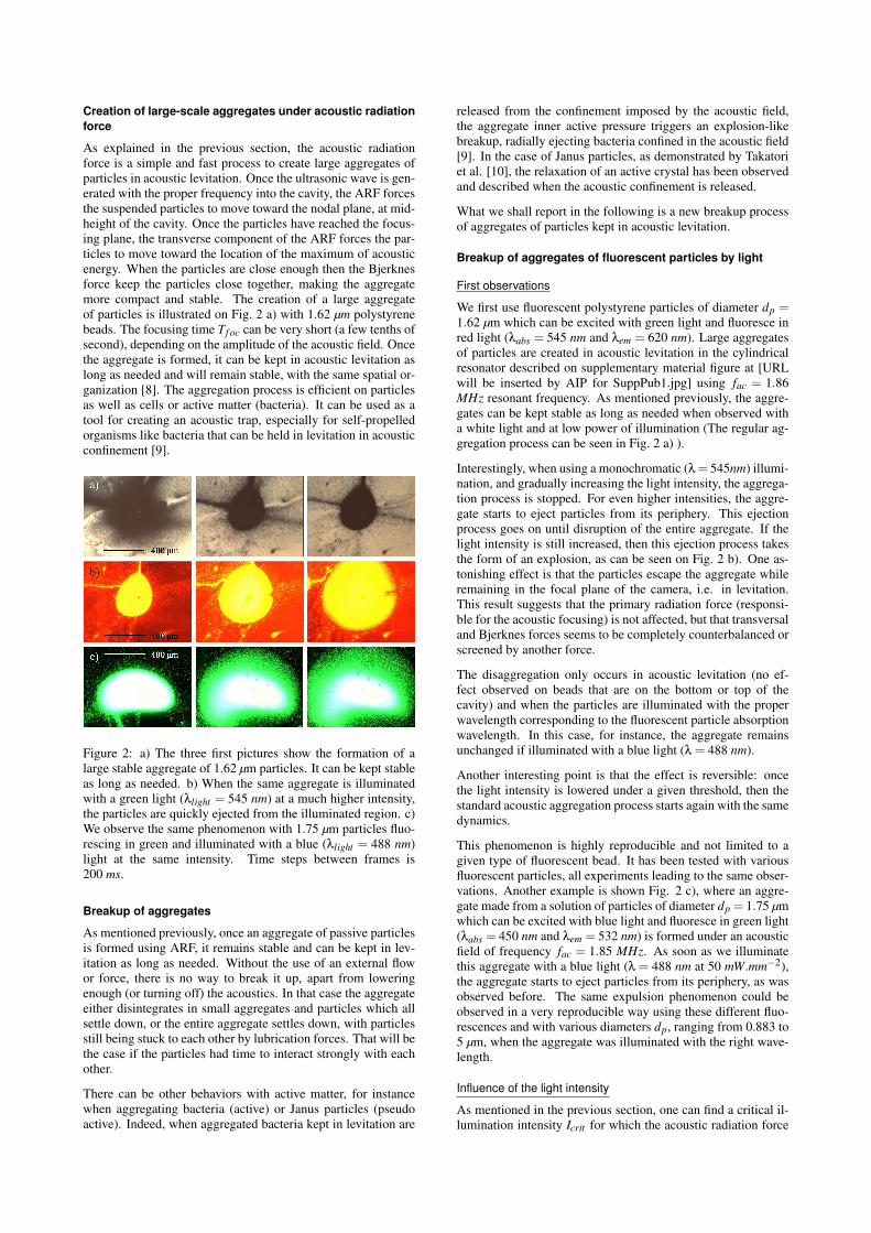
The previous experiments show a clear correlation betweenacoustics and illumination for the breakdown of aggregates. Toevaluate this coupling, we studied the evolution of the ejec-tion speed from the aggregates when varying the illuminationpower and amplitude of the ARF for a given suspension ofparticles (dp = 1.62 µm). The result is shown on Fig. 5 as aphase diagram: we represent the initial ejection speed of par-ticles from the aggregate as a function of illumination powerand acoustic energy applied to the aggregate, i.e. a contour plotof ve j(Plight ,〈Eac〉), the color bar being proportional to ve j . Asone can observe, the aggregate is locked in a stable state, pro-vided that the illumination power is below 10 mW.mm−2, or theacoustic energy of the ultrasound field is below 25 J.m−3. Oncethis threshold is crossed (solid red line on the phase diagram,
corresponding to the Brownian motion at the experiment tem-perature, for these particles), then we have a more or less linearevolution of the ejection speed as light power or acoustic en-ergy is increased. Interestingly, there seems to be an optimumfor the ejection speed, as increasing the light power no longerincreases the ejection velocity once the acoustic energy higherthan 160 J.m−3. One possible explanation for this behavior isthat for these high acoustic energies, the acoustic streaming isno longer negligible, and may interact with the expulsion pro-cess, leading to some errors in the estimation of the initial ejec-tion velocity.
1
1
1
11
1
1 1
2
2
2
2
2
2 2
3
3
3
3
33
4
4
4
4
44
5
5
5
55
6
6
6
6
6
7
7
7
7
8
8
8
8
9
9
9
9
10
10
10
10
11
111112
12
12
13
13
1314
14
15
1516
0 50 100 150 200Acoustic energy J.m -3
5
10
15
20
25
30
35
40
45
Ligh
t pow
er
= 5
45 n
m in
mW
.mm
-2
2
4
6
8
10
12
14
16
Eje
ctio
n sp
eed
in µ
m.s
-1
Figure 5: Determination of the phase diagram for an assem-bly of 1.62 µm red fluorescent particles. The ejection speed ofparticles from the aggregate are represented with a color scale,against the power of the light used on the aggregate and thesquared voltage applied to the piezoelectric ceramic, represent-ing the acoustic energy inside the resonator. The 1 µm.s−1 speedcontour has been identified as the threshold between stable ag-gregate and aggregate breakup zones.
These results may suggest an amplified photo-acoustic effect onparticles absorbing light in acoustic levitation. Indeed, photo-acoustic effect [11] takes place when a pulsed radiation is ab-sorbed by an object: the thermal expansion of the material in-duced by the absorption of optical radiation causes dilatationand mechanical motion of the object then creating a sound wavepropagating into the surrounding medium with the frequencyimposed by the illumination source. Each particle thus becomesan acoustic source when properly illuminated. In our case theillumination is constant but the particles are already subjectedto an acoustic force with a given pulsation frequency to createlarge aggregates in acoustic levitation. Both effects may leadto unexpected amplified photo-acoustic effect. The vibration ofthe particles induced by the ultrasounds may be amplified bythe energy injected by the illumination. Further investigationsare needed to clarify the origin of this phenomenon.
Conclusions
Choosing the proper geometric and acoustic parameters, it ispossible to control the aggregation process of micro particlesusing our in-house ultrasonic resonators. Once the aggregatesare formed, it is possible to keep them in acoustic levitation aslong as desired. The only way to break the aggregates is to turnoff the ultrasounds. Nevertheless we show that it is possible todestroy an aggregate of fluorescent particles just by illuminatingit at the proper absorption wavelength. This phenomenon de-pends on both the acoustic force amplitude and the illuminationpower : the expulsion of the particles can only be observed inacoustic levitation, suggesting a strong coupling between acous-tics and photonics effects. Above a given critical illuminationpower, the aggregate literally explodes. The expulsion of the
particles from the illuminated area can be very fast with an ex-pulsion velocity which depends on the injected power (acous-tic amplitude and illumination power). First experiments withdyed beads aggregates confirm that only the absorption proper-ties are important in the process, not the fluorescence properties.Early observations also show that the phenomenon is affectingliving cells such as red blood cells, opening the path to many ap-plications of these findings. This phenomenon, which may benamed optoacoustophoresis due to its dependence on both exci-tations, opens the path to many new manipulations and sortingprocesses of suspensions, combining both acoustic and opticalproperties of particles or cells. This new branch of acoustoflu-idics could be called optoacoustofluidics. The potential appli-cations are numerous for both diagnosis or production, such asfine cell separation for analysis or rare cell tagging in continu-ous flow systems.
References
[1] W. T. Coakley and J. F. Spengler, Analytical scale ultra-sonic standing wave manipulation of cells and microparti-cles, Ultrasonics , 38, 2000, 638–641.
[2] J. Hulstrm, O. Manneberg, K. Dopf, H. M. Hertz, H. Bris-mar, and M. Wiklund, Proliferation and viability of ad-herent cells manipulated by standing-wave ultrasound in amicrofluidic chip, Ultrasound in medicine and biology 33,2006, 175–181.
[3] L. V. King, On the acoustic radiation pressure on spheres,Proceedings of the Royal Society of London, Ser. A 147,1934, 212–240.
[4] K. Yosioka, Y. Kawasima,Acoustic radiation pressure ona compressible sphere, Acustica 5, 1955, 167–173.
[5] L. P. Gor’kov, On the forces acting on a small particle inan acoustic field in an ideal fluid, Sov. Phys. 6(9), 1962,773–775.
[6] S. M. Woodside, B. D. Bowen, J. M. Piret, Measurementof ultrasonic forces for particle-liquid separations, AIChEjournal 43, 1997, 1727–1736.
[7] G. Whitworth, M. A. Grundy, W. T. Coakley,Transportand harvesting of suspended particles using modulated ul-trasound, Ultrasonics 29, 1991, 439–444.
[8] D. Bazou, A. Castro, M. Hoyos, Controlled cell aggrega-tion in a pulsed acoustic field, Ultrasonics 52(7), 2012,842 – 850.
[9] S. Gutierrez-Ramos, M. Hoyos, J. Ruiz-Suarez, Inducedclustering of escherichia coli by acoustic fields, Scientificreports 8(1), 2018, 4668
[10] S. C. Takatori, R. De Dier, J. Vermant, J. F. Brady, Acous-tic trapping of active matter, Nature communications 72016.
[11] G. J. Diebold, A. C. Beveridge, T. J. Hamilton, The pho-toacoustic effect generated by an incompressible sphere,The Journal of the Acoustical Society of America 112(5),2002, 1780–1786.


![Sustainable Green Environment through Utilization of Waste ...€¦ · containing crushed glass aggregate materials (15-19). Study by [17] that the colour of glass aggregate particles](https://img.pdfslide.us/doc/110x75/6004c42c32f7c45de958684b/sustainable-green-environment-through-utilization-of-waste-containing-crushed.jpg)