Embed Size (px)
Citation preview
Journal of Applied Mathematics and Physics, 2014, 2, 1061-1068 Published Online November 2014 in SciRes. http://www.scirp.org/journal/jamp http://dx.doi.org/10.4236/jamp.2014.212121
How to cite this paper: Woo, K., Peterson, W.M. and Cairns, D.S. (2014) Selective Activation of Intrinsic Cohesive Elements. Journal of Applied Mathematics and Physics, 2, 1061-1068. http://dx.doi.org/10.4236/jamp.2014.212121
Selective Activation of Intrinsic Cohesive Elements Kyeongsik Woo1*, William M. Peterson2, Douglas S. Cairns2 1School of Civil Engineering, Chungbuk National University, Cheongju, Chungbuk, Korea 2Department of Mechanical & Industrial Engineering, Montana State University, Bozeman, MT, USA Email: *[email protected] Received September 2014
Abstract In this paper, a selective activation strategy is studied in order to alleviate the issue of added com-pliance in the intrinsic cohesive zone model applied to arbitrary crack propagation. This strategy proceeds by first inserting cohesive elements between bulk elements and subsequently tying the duplicated nodes across the interface using controllable multi-point constraints before the analy-sis begins. Then, during the analysis, a part of the multi-point constraints are selectively released, thereby reactivating the corresponding cohesive elements and allowing cracks to initiate and propagate along the bulk element boundaries. The strategy is implemented in Abaqus/Standard using a user-defined multi-point constraint subroutine. Analysis results indicate that the strategy significantly alleviates the added compliance problem and reduces the computation time.
Keywords Intrinsic CZM, Arbitrary Crack Propagation, Added Compliance, Selective Activation, Multi-Point Constraint
1. Introduction Recently, the cohesive zone model (CZM) has been increasingly used for the fracture analysis of engineering materials. The CZM gives an explicit and clear picture of the physical representation of cracks and can be easily implemented within the conventional finite element method. In the application of the CZM, cohesive elements are placed within the mesh between bulk material elements and thus provide potential crack paths at in-ter-element boundaries. The continuum response is modeled by the bulk elements while damage and fracture is represented by the cohesive elements. Unlike traditional LEFM approaches, the CZM requires neither the loca-tion of initial cracks nor for the crack propagation paths to be known [1] [2]. The basic idea of the CZM was in-troduced by Dugdale [3] and Barenblatt [4], and first utilized by Hillerborg [5] for the fracture analysis of con-crete materials. Since then, there have been numerous studies on the development and application of this versa-tile method in order to predict the fracture behavior of engineering materials (e.g., [6]-[10]).
Cohesive element behavior is governed by a traction-separation law (TSL) which describes the cohesive trac-tions across an equivalent fracture surface as a function of interfacial separation. The shape of the TSL may be
*Corresponding author.
K. Woo et al.
1062
defined in various forms in order to approximate the process of material failure, and exponential [7], bi-linear [9], and trapezoidal [10] TSLs are commonly used. In what is generally known referred to as the “intrinsic” CZM, TSLs that have an initially elastic region are used. As a result, the intrinsic CZMs tend to suffer from the well-known problem of artificial compliance problem, which may affect the global elastic response as well as the fracture behavior [11] [12]. This issue becomes particularly significant when a large number of cohesive elements are used, as in, for example, simulations of arbitrary crack growth throughout a material in which the crack paths are not known a priori. Alternatively, initially rigid cohesive element behavior may be achieved in a method known as “extrinsic” CZM, in which cohesive elements are adaptively inserted into the mesh only as needed during the analysis. In the extrinsic approach, the cohesive behavior is typically defined with a strictly decreasing TSL and thus the effect of artificial compliance problem is minimized (eg., [8] [12]-[14]). However, a fracture criterion is needed to determine when to insert cohesive elements, and the sophisticated management of complex data structures is required since the mesh changes continuously during the analysis.
In this study, a selective activation strategy was developed which alleviates the effects of added compliance issue inherent to the intrinsic CZM while avoiding the complexity of the extrinsic approach. In this strategy, the cohesive elements are inserted within the initial mesh but are subsequently deactivated by enforcing multi-point constraints (MPCs) which prevent the separation of cohesive element nodes. During the solution, the MPCs may then be selectively released upon satisfaction of a specified condition and the corresponding cohesive elements are reactivated. This approach was developed in the framework of the intrinsic CZM so that the advantage of representing the fracture process solely by a given TSL was retained. The strategy was implemented as a user subroutine to Abaqus/Standard, a readily available standard finite element code. A 3-dimeansional arbitrary crack propagation configuration was considered to demonstrate the effectiveness of the developed strategy in alleviating the artificial compliance problem. The effect of the choice of activation parameters on the predicted solution as well as on the computation times was investigated.
2. Analysis 2.1. Selective Activation of Cohesive Elements This section discusses the selective activation of intrinsic cohesive elements using controllable multi-point con-straints via a user subroutine in Abaqus. As discussed in the introduction, one of the major disadvantages of the intrinsic CZM is that the effective bulk elastic properties change due to the added compliance caused by the fi-nite initial stiffness in the TSL and the crack propagation path may additionally be altered. In this study, a strat-egy that can alleviate the added compliance effect was developed by selectively activating cohesive elements using controllable user multi-point constraints.
The selective activation of cohesive elements proceeds in 3 steps as shown below: STEP 1. Cohesive elements are inserted a priori between bulk elements. STEP 2. The cohesive elements are initially deactivated by tying the duplicate cohesive nodes by MPCs. STEP 3. During analysis, a small portion of MPCs in the region where cracks are likely to initiate or propa-
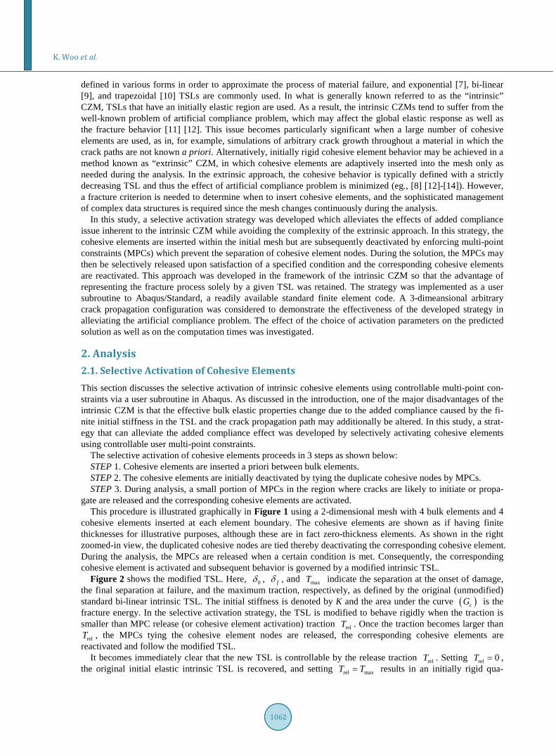
gate are released and the corresponding cohesive elements are activated. This procedure is illustrated graphically in Figure 1 using a 2-dimensional mesh with 4 bulk elements and 4
cohesive elements inserted at each element boundary. The cohesive elements are shown as if having finite thicknesses for illustrative purposes, although these are in fact zero-thickness elements. As shown in the right zoomed-in view, the duplicated cohesive nodes are tied thereby deactivating the corresponding cohesive element. During the analysis, the MPCs are released when a certain condition is met. Consequently, the corresponding cohesive element is activated and subsequent behavior is governed by a modified intrinsic TSL.
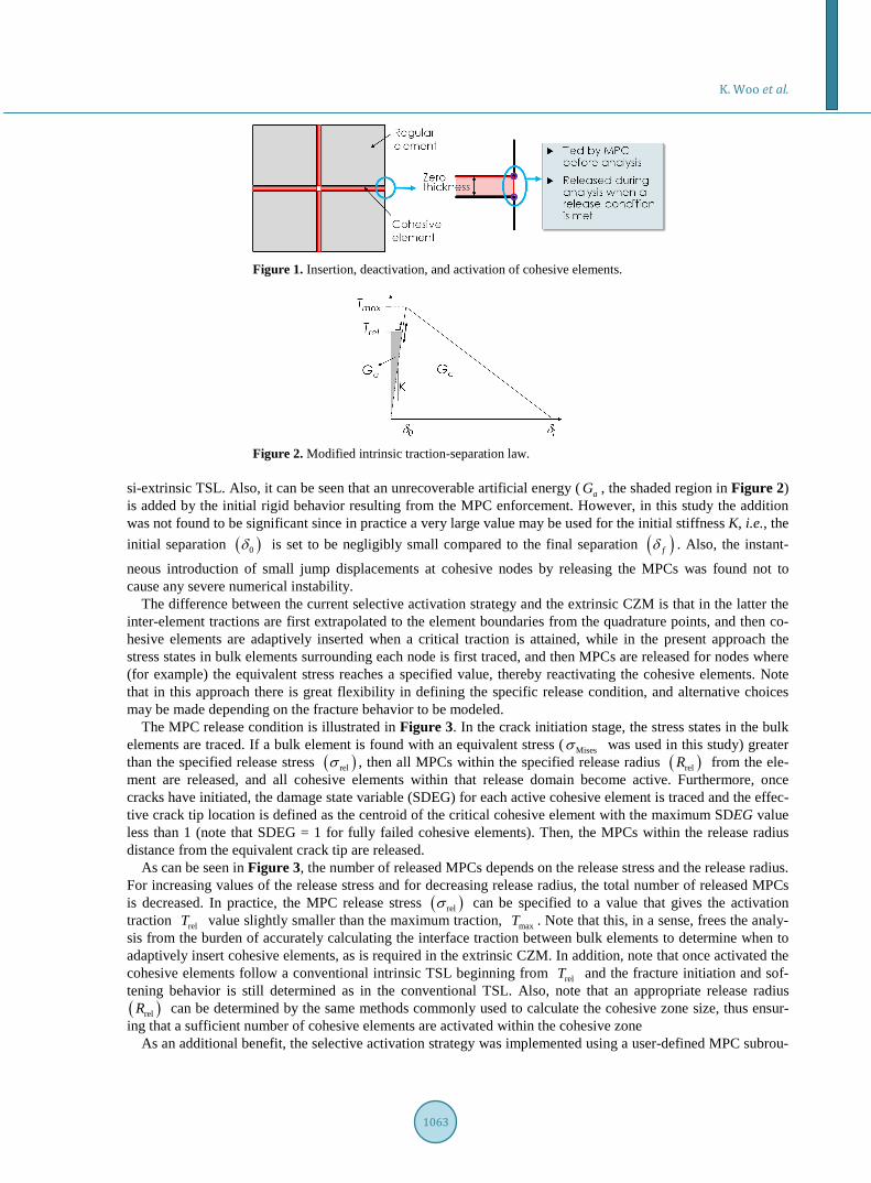
Figure 2 shows the modified TSL. Here, 0δ , fδ , and maxT indicate the separation at the onset of damage, the final separation at failure, and the maximum traction, respectively, as defined by the original (unmodified) standard bi-linear intrinsic TSL. The initial stiffness is denoted by K and the area under the curve ( )cG is the fracture energy. In the selective activation strategy, the TSL is modified to behave rigidly when the traction is smaller than MPC release (or cohesive element activation) traction relT . Once the traction becomes larger than
relT , the MPCs tying the cohesive element nodes are released, the corresponding cohesive elements are reactivated and follow the modified TSL.
It becomes immediately clear that the new TSL is controllable by the release traction relT . Setting rel 0T = , the original initial elastic intrinsic TSL is recovered, and setting rel maxT T= results in an initially rigid qua-
K. Woo et al.
1063
Figure 1. Insertion, deactivation, and activation of cohesive elements.
Figure 2. Modified intrinsic traction-separation law. si-extrinsic TSL. Also, it can be seen that an unrecoverable artificial energy ( aG , the shaded region in Figure 2) is added by the initial rigid behavior resulting from the MPC enforcement. However, in this study the addition was not found to be significant since in practice a very large value may be used for the initial stiffness K, i.e., the initial separation ( )0δ is set to be negligibly small compared to the final separation ( )fδ . Also, the instant-
neous introduction of small jump displacements at cohesive nodes by releasing the MPCs was found not to cause any severe numerical instability.
The difference between the current selective activation strategy and the extrinsic CZM is that in the latter the inter-element tractions are first extrapolated to the element boundaries from the quadrature points, and then co-hesive elements are adaptively inserted when a critical traction is attained, while in the present approach the stress states in bulk elements surrounding each node is first traced, and then MPCs are released for nodes where (for example) the equivalent stress reaches a specified value, thereby reactivating the cohesive elements. Note that in this approach there is great flexibility in defining the specific release condition, and alternative choices may be made depending on the fracture behavior to be modeled.
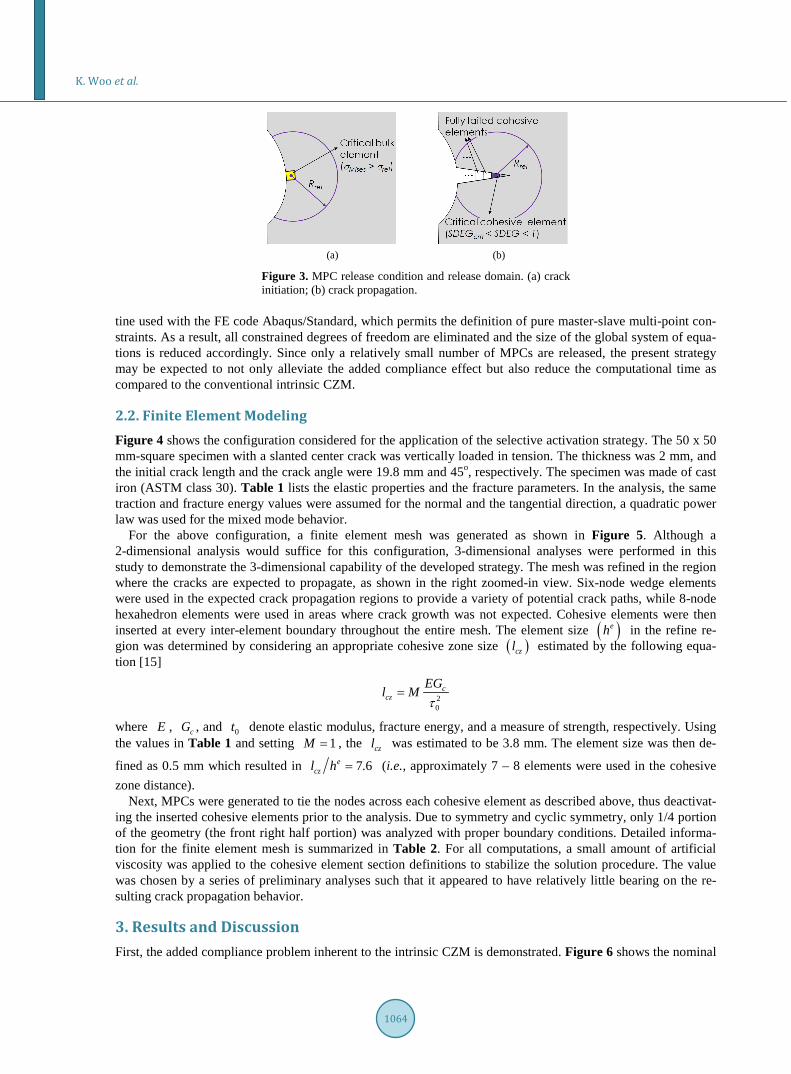
The MPC release condition is illustrated in Figure 3. In the crack initiation stage, the stress states in the bulk elements are traced. If a bulk element is found with an equivalent stress ( Misesσ was used in this study) greater than the specified release stress ( )relσ , then all MPCs within the specified release radius ( )relR from the ele-ment are released, and all cohesive elements within that release domain become active. Furthermore, once cracks have initiated, the damage state variable (SDEG) for each active cohesive element is traced and the effec-tive crack tip location is defined as the centroid of the critical cohesive element with the maximum SDEG value less than 1 (note that SDEG = 1 for fully failed cohesive elements). Then, the MPCs within the release radius distance from the equivalent crack tip are released.
As can be seen in Figure 3, the number of released MPCs depends on the release stress and the release radius. For increasing values of the release stress and for decreasing release radius, the total number of released MPCs is decreased. In practice, the MPC release stress ( )relσ can be specified to a value that gives the activation traction relT value slightly smaller than the maximum traction, maxT . Note that this, in a sense, frees the analy-sis from the burden of accurately calculating the interface traction between bulk elements to determine when to adaptively insert cohesive elements, as is required in the extrinsic CZM. In addition, note that once activated the cohesive elements follow a conventional intrinsic TSL beginning from relT and the fracture initiation and sof-tening behavior is still determined as in the conventional TSL. Also, note that an appropriate release radius ( )relR can be determined by the same methods commonly used to calculate the cohesive zone size, thus ensur-ing that a sufficient number of cohesive elements are activated within the cohesive zone
As an additional benefit, the selective activation strategy was implemented using a user-defined MPC subrou-
K. Woo et al.
1064
(a) (b)
Figure 3. MPC release condition and release domain. (a) crack initiation; (b) crack propagation.
tine used with the FE code Abaqus/Standard, which permits the definition of pure master-slave multi-point con-straints. As a result, all constrained degrees of freedom are eliminated and the size of the global system of equa-tions is reduced accordingly. Since only a relatively small number of MPCs are released, the present strategy may be expected to not only alleviate the added compliance effect but also reduce the computational time as compared to the conventional intrinsic CZM.
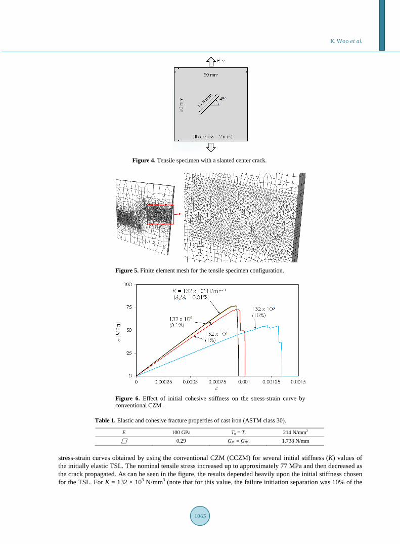
2.2. Finite Element Modeling Figure 4 shows the configuration considered for the application of the selective activation strategy. The 50 x 50 mm-square specimen with a slanted center crack was vertically loaded in tension. The thickness was 2 mm, and the initial crack length and the crack angle were 19.8 mm and 45o, respectively. The specimen was made of cast iron (ASTM class 30). Table 1 lists the elastic properties and the fracture parameters. In the analysis, the same traction and fracture energy values were assumed for the normal and the tangential direction, a quadratic power law was used for the mixed mode behavior.
For the above configuration, a finite element mesh was generated as shown in Figure 5. Although a 2-dimensional analysis would suffice for this configuration, 3-dimensional analyses were performed in this study to demonstrate the 3-dimensional capability of the developed strategy. The mesh was refined in the region where the cracks are expected to propagate, as shown in the right zoomed-in view. Six-node wedge elements were used in the expected crack propagation regions to provide a variety of potential crack paths, while 8-node hexahedron elements were used in areas where crack growth was not expected. Cohesive elements were then inserted at every inter-element boundary throughout the entire mesh. The element size ( )eh in the refine re-gion was determined by considering an appropriate cohesive zone size ( )czl estimated by the following equa-tion [15]
20
ccz
EGl M
τ=
where E , cG , and 0t denote elastic modulus, fracture energy, and a measure of strength, respectively. Using the values in Table 1 and setting 1M = , the czl was estimated to be 3.8 mm. The element size was then de-
fined as 0.5 mm which resulted in 7.6eczl h = (i.e., approximately 7 – 8 elements were used in the cohesive
zone distance). Next, MPCs were generated to tie the nodes across each cohesive element as described above, thus deactivat-
ing the inserted cohesive elements prior to the analysis. Due to symmetry and cyclic symmetry, only 1/4 portion of the geometry (the front right half portion) was analyzed with proper boundary conditions. Detailed informa-tion for the finite element mesh is summarized in Table 2. For all computations, a small amount of artificial viscosity was applied to the cohesive element section definitions to stabilize the solution procedure. The value was chosen by a series of preliminary analyses such that it appeared to have relatively little bearing on the re-sulting crack propagation behavior.
3. Results and Discussion First, the added compliance problem inherent to the intrinsic CZM is demonstrated. Figure 6 shows the nominal
K. Woo et al.
1065
Figure 4. Tensile specimen with a slanted center crack.
Figure 5. Finite element mesh for the tensile specimen configuration.
Figure 6. Effect of initial cohesive stiffness on the stress-strain curve by conventional CZM.
Table 1. Elastic and cohesive fracture properties of cast iron (ASTM class 30).
E 100 GPa Tn = Tt 214 N/mm2 0.29 GIC = GIIC 1.738 N/mm
stress-strain curves obtained by using the conventional CZM (CCZM) for several initial stiffness (K) values of the initially elastic TSL. The nominal tensile stress increased up to approximately 77 MPa and then decreased as the crack propagated. As can be seen in the figure, the results depended heavily upon the initial stiffness chosen for the TSL. For K = 132 × 103 N/mm3 (note that for this value, the failure initiation separation was 10% of the
K. Woo et al.
1066
Table 2. Numbers of elements and MPCs for 1/4 mesh.
Element type Number of elements
C3D8 C3D6
COH3D8
875 1,779 4,343
Number of MPCs 13,875
final failure separation), the elastic response before the fracture and the failure stress were significantly underes-timated. As the initial stiffness was increased, the added compliance effect was reduced and converged results were obtained. For the specific model under consideration, this convergence of the stress-strain curve was ob-tained when the initial stiffness was increased to 132 × 105 N/mm3 (i.e., the failure initiation separation was 0.1% of the final failure separation).
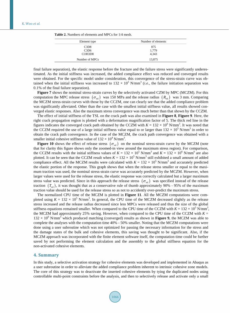
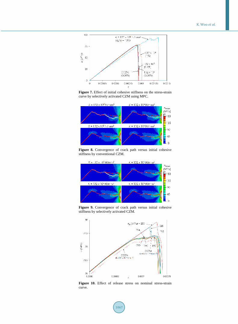
Figure 7 shows the nominal stress-strain curves by the selectively activated CZM by MPC (MCZM). For this computation the MPC release stress ( )relσ was 150 MPa and the release radius ( )relR was 3 mm. Comparing the MCZM stress-strain curves with those by the CCZM, one can clearly see that the added compliance problem was significantly alleviated. Other than the case with the smallest initial stiffness value, all results showed con-verged elastic responses. Also the maximum stress convergence was much better than that shown by the CCZM.
The effect of initial stiffness of the TSL on the crack path was also examined in Figure 8, Figure 9. Here, the right crack propagation region is plotted with a deformation magnification factor of 5. The thick red line in the figures indicates the converged crack path obtained by the CCZM with K = 132 × 106 N/mm3. It was noted that the CCZM required the use of a large initial stiffness value equal to or larger than 132 × 105 N/mm3 in order to obtain the crack path convergence. In the case of the MCZM, the crack path convergence was obtained with a smaller initial cohesive stiffness value of 132 × 104 N/mm3.
Figure 10 shows the effect of release stress ( )relσ on the nominal stress-strain curve by the MCZM (note that for clarity this figure shows only the zoomed-in view around the maximum stress region). For comparison, the CCZM results with the initial stiffness values of K = 132 × 105 N/mm3 and K = 132 × 106 N/mm6 are also plotted. It can be seen that the CCZM result when K = 132 × 105 N/mm3 still exhibited a small amount of added compliance effect. All the MCZM results were calculated with K = 132 × 105 N/mm3 and accurately predicted the elastic portion of the response. This graph shows that when the release stress smaller or equal to the maxi-mum traction was used, the nominal stress-strain curve was accurately predicted by the MCZM. However, when larger values were used for the release stress, the elastic response was correctly calculated but a larger maximum stress value was predicted. Since in this approach the release stress ( )relσ was specified instead of the release traction ( )relT , it was thought that as a conservative rule of thumb approximately 90% - 95% of the maximum traction value should be used for the release stress so as not to accidently over-predict the maximum stress.
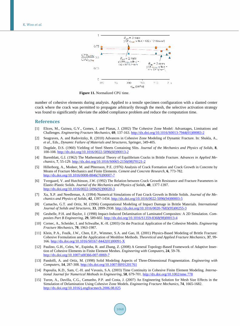
The normalized CPU time of the MCZM is plotted in Figure 11. All the MCZM computations were com-pleted using K = 132 × 105 N/mm3. In general, the CPU time of the MCZM decreased slightly as the release stress increased and the release radius decreased since less MPCs were released and thus the size of the global stiffness equations remained smaller. When compared to the CPU time of the CCZM with K = 132 × 105 N/mm3, the MCZM had approximately 25% saving. However, when compared to the CPU time of the CCZM with K = 132 × 106 N/mm3 which produced matching (converged) results as shown in Figure 9, the MCZM was able to complete the analyses with the computation time 40% - 50% smaller. Noting that the MCZM computations were done using a user subroutine which was not optimized for passing the necessary information for the stress and the damage states of the bulk and cohesive elements, this saving was thought to be significant. Also, if the MCZM approach was incorporated with the finite element software itself, the computation time could be further saved by not performing the element calculation and the assembly to the global stiffness equation for the non-activated cohesive elements.
4. Summary In this study, a selective activation strategy for cohesive elements was developed and implemented in Abaqus as a user subroutine in order to alleviate the added compliance problem inherent to intrinsic cohesive zone models. The core of this strategy was to deactivate the inserted cohesive elements by tying the duplicated nodes using controllable multi-point constraints before the analysis, and then to selectively release and activate only a small
K. Woo et al.
1067
Figure 7. Effect of initial cohesive stiffness on the stress-strain curve by selectively activated CZM using MPC.
Figure 8. Convergence of crack path versus initial cohesive stiffness by conventional CZM.
Figure 9. Convergence of crack path versus initial cohesive stiffness by selectively activated CZM.
Figure 10. Effect of release stress on nominal stress-strain curve.
K. Woo et al.
1068
Figure 11. Normalized CPU time.
number of cohesive elements during analysis. Applied to a tensile specimen configuration with a slanted center crack where the crack was permitted to propagate arbitrarily through the mesh, the selective activation strategy was found to significantly alleviate the added compliance problem and reduce the computation time.
References [1] Elices, M., Guinea, G.V., Gomes, J. and Planas, J. (2002) The Cohesive Zone Model: Advantages, Limitations and
Challenges. Engineering Fracture Mechanics, 69, 137-163. http://dx.doi.org/10.1016/S0013-7944(01)00083-2 [2] Seagraves, A. and Radovitzky, R. (2010) Advances in Cohesive Zone Modeling of Dynamic Fracture. In: Shukla, A.,
et al., Eds., Dynamic Failure of Materials and Structures, Springer, 349-405. [3] Dugdale, D.S. (1960) Yielding of Steel Sheets Containing Slits. Journal of the Mechanics and Physics of Solids, 8,
100-108. http://dx.doi.org/10.1016/0022-5096(60)90013-2 [4] Barenblatt, G.I. (1962) The Mathematical Theory of Equilibrium Cracks in Brittle Fracture. Advances in Applied Me-
chanics, 7, 55-129. http://dx.doi.org/10.1016/S0065-2156(08)70121-2 [5] Hillerborg, A., Modeer, M. and Phtersson, P.E. (1976) Analysis of Crack Formation and Crack Growth in Concrete by
Means of Fracture Mechanics and Finite Elements. Cement and Concrete Research, 6, 773-782. http://dx.doi.org/10.1016/0008-8846(76)90007-7
[6] Tvergaard, V. and Hutchinson, J.W. (1992) The Relation between Crack Growth Resistance and Fracture Parameters in Elastic-Plastic Solids. Journal of the Mechanics and Physics of Solids, 40, 1377-1397. http://dx.doi.org/10.1016/0022-5096(92)90020-3
[7] Xu, X.P. and Needleman, A. (1994) Numerical Simulations of Fast Crack Growth in Brittle Solids. Journal of the Me-chanics and Physics of Solids, 42, 1397-1434. http://dx.doi.org/10.1016/0022-5096(94)90003-5
[8] Camacho, G.T. and Ortiz, M. (1996) Computational Modeling of Impact Damage in Brittle Materials. International Journal of Solids and Structures, 33, 2899-2938. http://dx.doi.org/10.1016/0020-7683(95)00255-3
[9] Geubelle, P.H. and Baylor, J. (1998) Impact-Induced Delamination of Laminated Composites: A 2D Simulation. Com- posites Part B Engineering, 29, 589-602. http://dx.doi.org/10.1016/S1359-8368(98)00013-4
[10] Cornec, A., Scheider, I. and Schwalbe, K.-H. (2003) On the Practical Application of the Cohesive Models. Engineering Fracture Mechanics, 70, 1963-1987.
[11] Klein, P.A., Foulk, J.W., Chen, E.P., Wimmer, S.A. and Gao, H. (2001) Physics-Based Modeling of Brittle Fracture: Cohesive Formulation and the Application of Meshfree Methods. Theoretical and Applied Fracture Mechanics, 37, 99- 166. http://dx.doi.org/10.1016/S0167-8442(01)00091-X
[12] Paulino, G.H., Celes, W., Espinha, R. and Zhang, Z. (2008) A General Topology-Based Framework of Adaptive Inser-tion of Cohesive Elements in Finite Element Meshes. Engineering with Computers, 24, 59-78. http://dx.doi.org/10.1007/s00366-007-0069-7
[13] Pandolfi, A. and Ortiz, M. (1998) Solid Modeling Aspects of Three-Dimensional Fragmentation. Engineering with Computers, 14, 287-308. http://dx.doi.org/10.1007/BF01201761
[14] Papoulia, K.D., Sam, C.-H. and Vavasis, S.A. (2003) Time Continuity in Cohesive Finite Element Modeling. Interna-tional Journal for Numerical Methods in Engineering, 58, 679-701. http://dx.doi.org/10.1002/nme.778
[15] Turon, A., Davilla, C.G., Camanho, P.P. and Costa, J. (2007) An Engineering Solution for Mesh Size Effects in the Simulation of Delamination Using Cohesive Zone Models. Engineering Fracture Mechanics, 74, 1665-1682. http://dx.doi.org/10.1016/j.engfracmech.2006.08.025