Embed Size (px)
Citation preview

APC by Schneider Electric 01/2012 edition p. 1
Selection of the UPS configuration
Contents Types of possible configurations .................................. 2 Selection table and corresponding ranges ................... 5 Diagram no. 1 .................................................................. 6 Single UPS Diagram no. 2 .................................................................. 7 Active redundancy with two integrated parallel UPS units Diagram no. 3 .................................................................. 8 Active redundancy with integrated parallel UPS units and external maintenance bypass Diagram no. 4 .................................................................. 9 Isolated redundancy with two UPS units Diagram no. 5 .................................................................. 10 Active redundancy with parallel UPS units and centralised static-switch cubicle (SSC) Diagram no. 6 .................................................................. 11 Active redundancy with parallel UPS units and total isolation, single busbar Diagram no. 7 .................................................................. 12 Active redundancy with parallel UPS units and total isolation, double busbar Diagram no. 8 .................................................................. 13 Active redundancy with parallel UPS units, double SSC and total isolation, single busbar Diagram no. 9 .................................................................. 14 Active redundancy with parallel UPS units, double SSC and total isolation, double busbar Diagram no. 10 ................................................................ 15 Isolated redundancy with N+1 UPS units Diagram no. 11 ................................................................ 16 Redundant distribution with static transfer switch (STS) Diagram no. 12 ................................................................ 18 Redundant distribution with static transfer switch (STS) and PDU

APC by Schneider Electric 01/2012 edition p. 2
Types of possible configurations
Single source The load is supplied by a single set of UPSs. Multi-source The load is supplied by more than one set of UPSs.
Fig. 2.1. Basic diagrams.
Single UPS This is the standard double-conversion UPS (see fig. 2.2). Single UPSs can be used to form redundant configurations as shown in diagrams 4 and 11.
Single UPS, see Ch. 1 p. 9 and Ch. 4 p. 14 "UPS components and operation".
Standard diagrams: No. 1 No. 4 No. 11
Fig. 2.2. Double-conversion single UPS. Parallel UPS Purpose of parallel connection Parallel connection of a number of identical UPS units is the means to: • increase the power rating, • establish redundancy that increases MTBF and availability, • make the installation scalable. Two types of MGETM GalaxyTM UPS units can be connected in parallel: • integrated parallel UPS units: each UPS unit includes an automatic bypass and a manual maintenance bypass (fig. 2.2). The manual bypass may be common to the entire system and located in an external cubicle (e.g. fig. 2.3). • parallel UPS units with a centralised static-switch cubicle (SSC) (e.g. fig. 2.4). Modular UPS UPSs of the SymmetraTM range are true modular parallel systems. They are made up of dedicated and redundant modules (power, intelligence, battery and bypass), all engineered into a design that is easily and efficiently serviceable and scalable. Identical plug-in power modules can be easily added in parallel as demand grows or as higher levels of availability are required (e.g. up to four 16 kW modules for Symmetra PX 48 with N+1 redundancy). The modules are hot-swappable. Modular design with plug-in power modules improves dependability, in particular maintainability and availability, as well the upgradeability of the installation.
Basic diagrams
UPS configurations
APC by Schneider Electric 01/2012 edition p. 3
Types of possible configurations (Cont.)
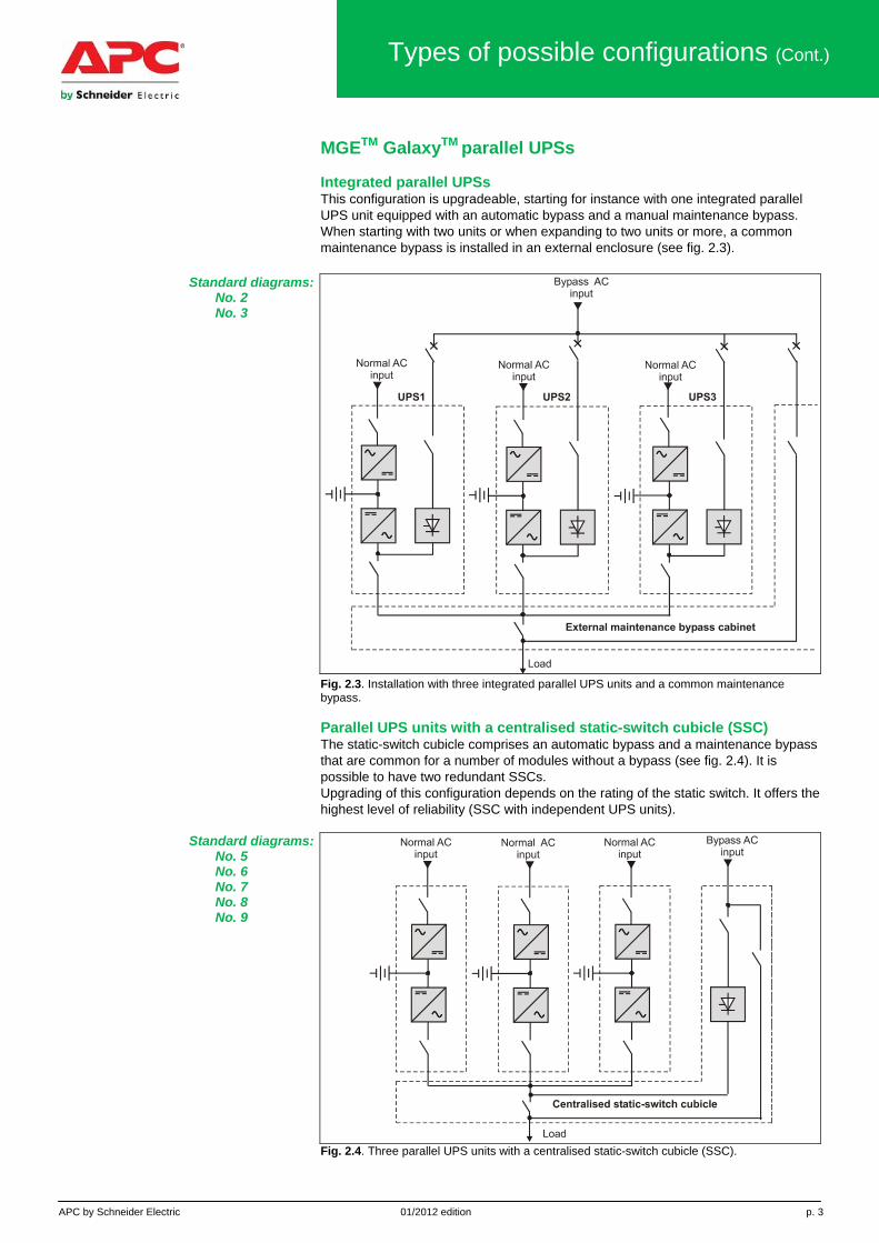
MGETM GalaxyTM parallel UPSs Integrated parallel UPSs This configuration is upgradeable, starting for instance with one integrated parallel UPS unit equipped with an automatic bypass and a manual maintenance bypass. When starting with two units or when expanding to two units or more, a common maintenance bypass is installed in an external enclosure (see fig. 2.3).
Standard diagrams: No. 2 No. 3
Fig. 2.3. Installation with three integrated parallel UPS units and a common maintenance bypass. Parallel UPS units with a centralised static-switch cubicle (SSC) The static-switch cubicle comprises an automatic bypass and a maintenance bypass that are common for a number of modules without a bypass (see fig. 2.4). It is possible to have two redundant SSCs. Upgrading of this configuration depends on the rating of the static switch. It offers the highest level of reliability (SSC with independent UPS units).
Standard diagrams: No. 5 No. 6 No. 7 No. 8 No. 9
Fig. 2.4. Three parallel UPS units with a centralised static-switch cubicle (SSC).

APC by Schneider Electric 01/2012 edition p. 4
Types of possible configurations (Cont.)
Parallel connection with redundancy The parallel configurations presented above may or may not be redundant. Without redundancy All the UPS units are required to supply the load. Failure of one unit means the entire system shuts down. With active redundancy (N+1, N+2, etc.) Only N UPS units are required to supply the load, even though N+1, N+2 or more units are installed. This ensures a secure supply of power to the load even if one (for N+1 redundancy) or two (for N+2 redundancy) UPS units fail or require maintenance. Optimum redundancy of non-modular UPSs For non-modular systems, differences in the lengths or tightening torques of cables connecting the different units can lead to problems concerning the impedance upstream and downstream of each UPS. For this reason, the highest MTBF is obtained for redundant systems with just two UPSs (fig. 2.5). For modular UPS systems, module interconnections are an integral part of the system, thereby eliminating installation problems that can lower the MTBF as more units are added.
Fig. 2.5. For non-modular redundant UPS systems, the best MTBF is obtained with two units. Redundant distribution with an STS All the loads are supplied by more than one UPS source (two single UPS units in figure 4.5). Each source can be made up of a number of parallel-connected units offering active redundancy. Use of a static transfer switch (STS) ensures transfer of the load between the sources in the event of a downstream fault (while avoiding any risk of fault propagation) or for maintenance. Power distribution units (PDUs) can be used to complete this distribution configuration, offering: • load management, • multi-channel supply of power to the loads (dual attach), • isolation of parts of the installation for maintenance or upgrading. This type of configuration ensures a very high degree of availability and offers a number of installation-upgrade possibilities.
Standard diagrams: No. 11 No. 12
Fig 2.6. Redundant distribution with an STS.

APC by Schneider Electric 01/2012 edition p. 5
Selection table and corresponding ranges
Criteria for comparison The table below compares the standard diagrams of this chapter, mainly related to MGETM GalaxyTM UPSs, according to the following criteria.
Availability A level of availability meeting the needs of the application. Figures are based on: • an estimated level of utility-power availability of 99.9% (the European average), • an MTTR of ten hours as per standard MIL-HDB-217-F level 2 (U.S. military) and IEEE. Maintainability Ensure easy maintenance of the equipment under safe conditions for personnel and without interrupting operation. Upgradeability It must be possible to upgrade the installation over time, taking into account both the need to expand the installation gradually and operating requirements. Discrimination and non propagation of faults It must be possible to limit faults to as small a part of the installation as possible, while enabling servicing without stopping operations. Installation operation and management Make operations easier by providing the means to anticipate events via installation supervision and management systems. Single-source configurations
Standard diagram number
Criteria for comparison Availability MTBF Maintainability Upgradeability Comment
1. Single UPS 99.99790% M1=475 000 h * 4 parallel-connected UPS units
Reference for calculations
2. 2 integrated parallel UPS units
99.99947% up to 4 x M1 ** 4 parallel-connected UPS units
3. Integrated parallel units and external maintenance bypass
99.99947% up to 4 x M1 ** 4 parallel-connected UPS units
4. Isolated redund. 99.99970% 6.8 x M1 ** Flexible 5. Centralised SSC
99.99968% 6.5 x M1 ** 6 parallel-connected UPS units
6. Total isolation, single busbar
99.99968% 6.5 x M1 *** 6 parallel-connected UPS units
7. Total isolation, double busbar
99.99968% 6.5 x M1 *** 6 parallel-connected UPS units
8. Total isolation, single busbar
99.99968% 6.5 x M1 **** 6 parallel-connected UPS units
9. Total isolation, double busbar
99.99968% 6.5 x M1 **** 6 parallel-connected UPS units
Multi-source configurations Standard
diagram numberCriteria for comparison Availability MTBF Maintainability Upgradeability Comment
10. Isolated redundancy
99.99970% 7 x M1 ** No limit
11. With STS 99.99970% 7 x M1 **** No limit to the power rating
No propagation of faults
12. STS + PDU 99.99930% The highest level of availability
**** No limit to the power rating
+ load management
**** excellent *** good ** fair * poor

APC by Schneider Electric 01/2012 edition p. 6
Diagram no. 1. Single UPS
Fig. 2.7. Double-conversion single-UPS unit. This is the basic solution for UPS installations. The double-conversion UPS unit supplies high-quality voltage, whatever the level of disturbances in the utility power. Availability of power for the load 99.99790% and an MTBF of 475 000 hours, compared to a utility MTBF of 96 hours. UPS maintenance Made easy due to the built-in bypass for supply of power to the load during servicing. Possible upgrades On site by connecting several identical UPS units in parallel. Applicable ranges MGETM GalaxyTM 3500, PW, 5000, 7000, 9000. Symmetra PX range and Symmetra MW

APC by Schneider Electric 01/2012 edition p. 7
Diagram no. 2. Active redundancy with two
integrated parallel UPS units
Fig. 2.8. Active redundancy with two integrated parallel UPS units. A simple solution where the UPS units share the load. Availability of power for the load 99.99947% and an MTBF up to four times higher than that for a single UPS. UPS maintenance During maintenance on one unit, the load remains protected by the other. Possible upgrades Several identical UPS units can be connected in parallel and equipped with an external maintenance bypass. Special characteristics • The automatic-bypass function is ensured by managing the static switches. • Centralised monitoring of the various modules. • Can be used only with two identical units. Applicable ranges MGETM GalaxyTM 3500, PW, 5000, 7000, 9000.
APC by Schneider Electric 01/2012 edition p. 8
Diagram no. 3. Active redundancy with integrated parallel UPS units and external
maintenance bypass
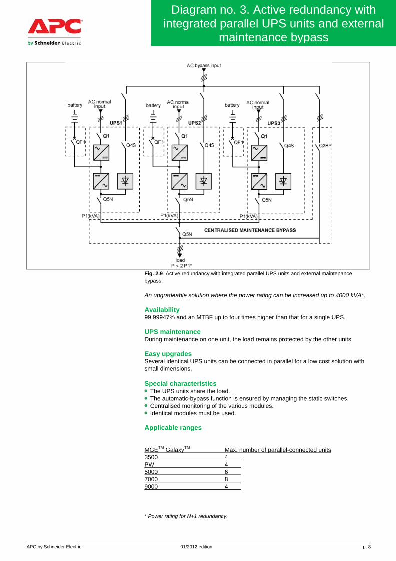
Fig. 2.9. Active redundancy with integrated parallel UPS units and external maintenance bypass. An upgradeable solution where the power rating can be increased up to 4000 kVA*. Availability 99.99947% and an MTBF up to four times higher than that for a single UPS. UPS maintenance During maintenance on one unit, the load remains protected by the other units. Easy upgrades Several identical UPS units can be connected in parallel for a low cost solution with small dimensions. Special characteristics • The UPS units share the load. • The automatic-bypass function is ensured by managing the static switches. • Centralised monitoring of the various modules. • Identical modules must be used. Applicable ranges MGETM GalaxyTM Max. number of parallel-connected units 3500 4 PW 4 5000 6 7000 8 9000 4 * Power rating for N+1 redundancy.

APC by Schneider Electric 01/2012 edition p. 9
Diagram no. 4. Isolated redundancy with
two UPS units
Fig. 2.10. Isolated redundancy with two UPS units. An extremely flexible solution that can combine heterogeneous and distant UPS units. It also offers improved backup time and is perfectly suited to the technology implemented by MGE Galaxy UPSs from APC by Schneider Electric which provide excellent withstand capacity for load step changes. Availability 99.99970% and an MTBF 6.8 times higher than that of a single UPS. UPS maintenance During maintenance on one unit, the load remains protected. Special characteristics • For a single load, the two UPS units have the same power rating, but if there is a second load (possible load), the rating of the backup UPS unit must be adapted correspondingly. • No control wires between the UPS units. Applicable ranges MGETM GalaxyTM 3500, PW, 5000, 7000, 9000.
APC by Schneider Electric 01/2012 edition p. 10
Diagram no. 5. Active redundancy with parallel units and centralised static-switch
cubicle (SSC)
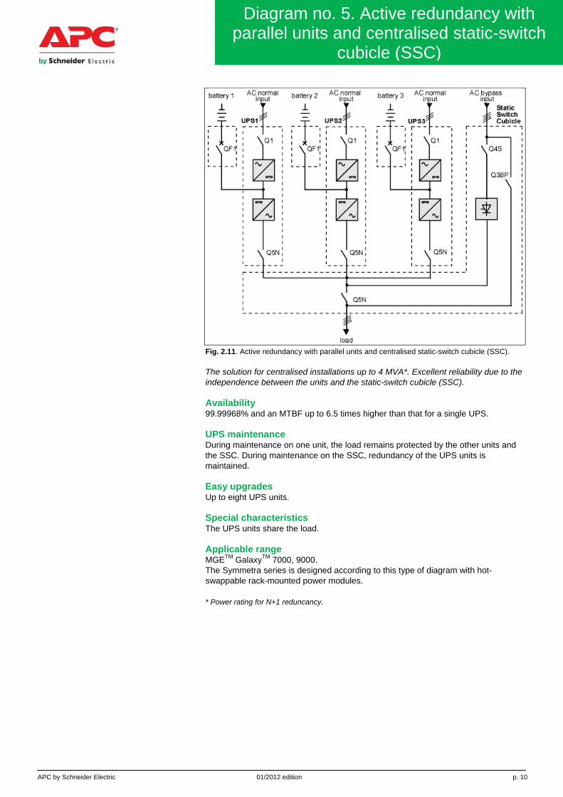
Fig. 2.11. Active redundancy with parallel units and centralised static-switch cubicle (SSC). The solution for centralised installations up to 4 MVA*. Excellent reliability due to the independence between the units and the static-switch cubicle (SSC). Availability 99.99968% and an MTBF up to 6.5 times higher than that for a single UPS. UPS maintenance During maintenance on one unit, the load remains protected by the other units and the SSC. During maintenance on the SSC, redundancy of the UPS units is maintained. Easy upgrades Up to eight UPS units. Special characteristics The UPS units share the load. Applicable range MGETM GalaxyTM 7000, 9000. The Symmetra series is designed according to this type of diagram with hot-swappable rack-mounted power modules. * Power rating for N+1 reduncancy.
APC by Schneider Electric 01/2012 edition p. 11
Diagram no. 6. Active redundancy with parallel UPS units and total isolation, single
busbar
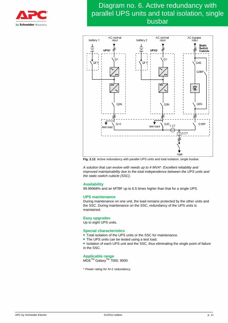
Fig. 2.12. Active redundancy with parallel UPS units and total isolation, single busbar. A solution that can evolve with needs up to 4 MVA*. Excellent reliability and improved maintainability due to the total independence between the UPS units and the static-switch cubicle (SSC). Availability 99.99968% and an MTBF up to 6.5 times higher than that for a single UPS. UPS maintenance During maintenance on one unit, the load remains protected by the other units and the SSC. During maintenance on the SSC, redundancy of the UPS units is maintained. Easy upgrades Up to eight UPS units. Special characteristics • Total isolation of the UPS units or the SSC for maintenance. • The UPS units can be tested using a test load. • Isolation of each UPS unit and the SSC, thus eliminating the single point of failure in the SSC. Applicable range MGETM GalaxyTM 7000, 9000. * Power rating for N+1 redundancy.

APC by Schneider Electric 01/2012 edition p. 12
Diagram no. 7. Active redundancy with parallel UPS units and total isolation, double
busbar
Fig. 2.13. Active redundancy with parallel UPS units, double SSC and total isolation, double busbar. A solution that can evolve with needs up to 4 MVA*. Excellent reliability and improved maintainability due to the total independence between the UPS units, the static-switch cubicle (SSC) and the busbars. Availability 99.99968% and an MTBF up to 6.5 times higher than that for a single UPS. UPS maintenance During maintenance on the UPS units and one busbar, the load remains protected by the other units and the SSC, which are parallel-connected to the second busbar. During maintenance on the SSC, redundancy of the UPS units is maintained. Easy upgrades Up to eight UPS units. Special characteristics • Transfer from one busbar to the other without disturbing the load. • Total isolation of the UPS units or the SSC for maintenance. • Isolation of each UPS unit and the SSC, thus eliminating the single point of failure in the SSC. Applicable range MGETM GalaxyTM 7000, 9000. * Power rating for N+1 redundancy.

APC by Schneider Electric 01/2012 edition p. 13
Diagram no. 8. Active redundancy with parallel UPS units, double SSC and total
isolation, single busbar
Fig. 2.14. Active redundancy with parallel UPS units, double SSC and total isolation, single busbar. An upgradeable solution offering improved maintainability due to the total redundancy of the UPS units and the static-switch cubicles (SSC). Availability 99.99968% and an MTBF up to 6.5 times higher than that for a single UPS. UPS maintenance During maintenance on the UPS units and one SSC, the load remains protected by the other units and the second SSC. During maintenance on one SSC, redundancy of the UPS units is maintained. Easy upgrades Up to eight UPS units. Special characteristics • Only one SSC is active, the other is on stand-by and transfer of the UPS units from one to the other takes place without disturbing the load. • During operation on the bypass, the load is split 50/50 between the two SSCs. • Total isolation of each SSC for maintenance. • Parallel connection of the UPS units in the output cabinet eliminates the single point of failure in an SSC. • The possibility of installing the SSCs in two separate rooms increases system availability in the event of fire or other problems. Applicable range MGETM GalaxyTM 7000, 9000.

APC by Schneider Electric 01/2012 edition p. 14
Diagram no. 9. Active redundancy with parallel UPS units, double SSC and total
isolation, double busbar
Fig. 2.15. Active redundancy with parallel UPS units, double SSC and total isolation, double busbar. A solution for two evolving loads with different needs in terms of power ratings and redundancy. Availability 99.99968% and an MTBF up to 6.5 times higher than that for a single UPS. UPS maintenance During maintenance on one UPS unit and one SSC, the load remains protected by the other units and the second SSC. During maintenance on one SSC, redundancy of the UPS units is maintained. Easy upgrades Up to eight UPS units. Special characteristics • During operation of only one load, only one SSC is active, the other is on stand-by and transfer of the UPS units from one to the other takes place without disturbing the load. • During operation of the two different loads, both SSCs are active, each with a number of assigned UPS units. • Parallel connection of the UPS units in the output cabinet eliminates the single point of failure in an SSC. • The possibility of installing the SSCs in two separate rooms increases system availability in the event of fire or other problems. Applicable range MGETM GalaxyTM 7000, 9000.

APC by Schneider Electric 01/2012 edition p. 15
Diagram no. 10. Isolated redundancy N+1
Fig. 2.16. Isolated redundancy N+1. Solution combining heterogeneous and distant UPS units to protect a number of independent loads. Availability of power for the load Greater than 99.99970% and an MTBF up to seven times higher than that for a single UPS. UPS maintenance During maintenance on one UPS unit, the load remains protected. However, the UPS units are not totally isolated (servicing under energised conditions). Possible upgrades No limit to the power rating. Short-circuit propagation Impossible between the sources. Special characteristics • Short-circuit capacity is lower than in a configuration with parallel UPS units • (Isc, discrimination, crest factor, etc.). • Sizing of the backup UPS must take into account the number of UPS units downstream, their power ratings and their criticality, as well as any future plans for the installation (generally speaking, the backup UPS has a parallel configuration). • All the advantages of isolated redundancy (diagram no. 4). Applicable ranges MGETM GalaxyTM 3500, 5000, 7000.

APC by Schneider Electric 01/2012 edition p. 16
Diagram no. 11. Redundant distribution with
STS
Fig. 2.17. Redundant distribution with STS units.
APC by Schneider Electric 01/2012 edition p. 17
Diagram no. 11. Redundant distribution with
STS (Cont.)
The best solution in terms of availability, site operation and safety. It is the only solution that deals with power distribution through to the loads. It is particularly flexible and makes for easy adaptation of redundancy to the needs of the load. Availability of power for the load Greater than 99.9999%, the highest level of availability! UPS maintenance Total distribution redundancy and servicing under no-load conditions make for maximum safety during maintenance. Easy upgrades Using single-UPS units and with no limit to the total power rating, upgrading is made easy by the capacity to partially isolate distribution subassemblies. Fault propagation Load segmenting and the technology employed in Upsilon STS units (break-before-make source transfer with no interruption to the loads) ensures isolation of loads from disturbances caused by other, faulty loads. Easy operation Automatic or manual source transfer. Continuous monitoring of the sources (11 parameters and internal circuits). Secure transfer of desynchronised sources. Special characteristics • The synchronisation module ensures perfect source synchronisation under all conditions (long outages, etc.). • Selection of the load distribution for the UPS units. • The UPS units can be heterogeneous and remote from the load. Applicable ranges All 3-phase ranges from APC by Schneider Electric: MGETM GalaxyTM and SymmetraTM.

APC by Schneider Electric 01/2012 edition p. 18
Diagram no. 12 . Active redundancy with
parallel UPS and a common battery
Fig. 2.18. Redundant distribution with STS units and PDU. Redundancy is built into each level, including the PDUs, the Upsilon STS units, the Galaxy UPS units and the synchronisation modules. Same advantages as diagram no. 11, plus: • Capacity to enhance the reliability of a particular point in the installation. • Four different supply channels to dual-attach servers. Applicable ranges All 3-phase ranges from APC by Schneider Electric: MGETM GalaxyTM and SymmetraTM.
PDU 1
PDU 2
PDU 3